

Page 1

WRC-1
Wireless Remote Control Instruction Manual
As of: June 2000
ALL ARTWORK, PICTURES AND TEXTS ARE COVERED BY OUR COPY-RIGHT.
HEY MUST NOT BE COPIED FOR REPRODUCTION (E.G. ON CD-ROM DISKS OR INTERNET-SITES) OR USED IN THEIR ENTIRE FORM OR IN EXCERPTS WITHOUT OUR PREVIOUS WRITTEN AGREEMENT.
T
F YOU ARE DOWNLOADING PDF-FILES FROM OUR INTERNET HOME-PAGE FOR YOUR PERSONAL USE, MAKE SURE TO CHECK FOR UPDATED VERSIONS.
I
E CANNOT TAKE ANY LIABILITY WHATSOEVER FOR DOWNLOADED FILES, AS TECHNICAL DATA ARE SUBJECT TO CHANGE WITHOUT NOTICE.
W
Page 2
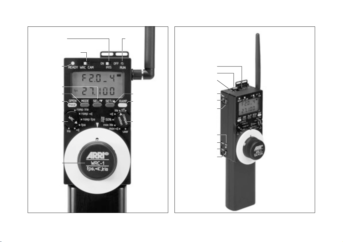
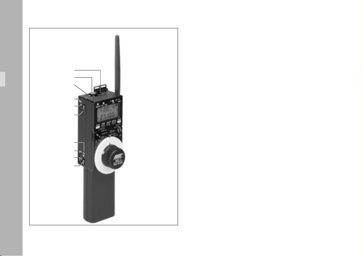
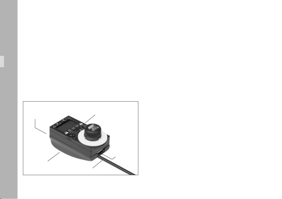
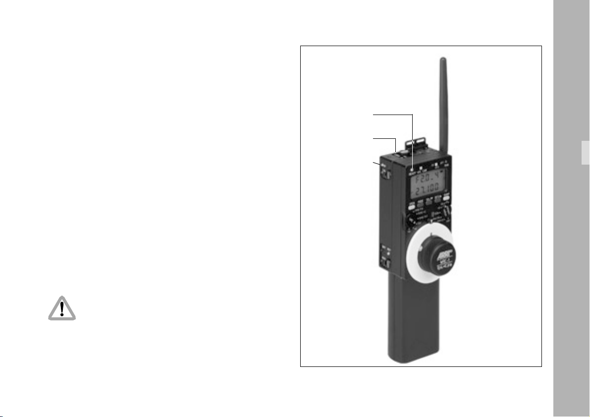
IRIS sliding switch
WRC/CAM sliding switch
RUN-LED
READY-LED
SEL button
MODE button
OPEN/PHASE
button
WRC
rotary switch
handwheel
SET button
RAMP button
COMPENSATION
rotary switch
RELEASE button
radio channel
ON button
RF-LED
CAL-LED
CAL button
READY-LED
BAT-LED
RUN-LED
RUN button
Page 3

1. Contents
2. Safety Instructions ..........................................7
Explanation of the Symbols in this Instruction Manual .......7
Product specifications .................................................7
3. Introduction ......................................................9
3.1 Some typical applications ..........................10
Exposure compensation .............................10
Altering the depth of field .......................... 10
Speed ramps ............................................11
3.2 Functions ..................................................12
3.2.1 CAM mode............................................... 12
3.2.2 WRC mode...............................................13
3.2.2.1 Overview of the settings available
with the WRC rotary switch ........................14
3.2.2.2 Overview of the settings available
with the COMPENSATION rotary switch .....15
4. Setup ...............................................................17
4.1 WRC-1 in wireless mode ........................... 17
Required system components...................... 17
4.1.1 Mounting the WRC-1 on the
Wireless Main Unit (WMU-1).....................18
4.1.2 Attaching the UMC-1 and URM-1
to the camera ........................................... 19
Setup with Iris control ................................22
Mounting the CLM-2 motor
with/without console .................................22
4.2 WRC-1 in cable mode ............................... 24
Required system components...................... 24
4.2.1 Mounting the WRC-1 on the
Wireless Handgrip Attachment (WHA-1) ....24
Contents
3
Page 4

5. Operation .......................................................25
5.1 Operating modes ...................................... 25
5.1.1 CAM mode............................................... 25
5.1.2 WRC mode............................................... 26
5.2 Switching on .............................................27
Contents
5.3 Important instructions ................................ 28
5.4 Using the menus........................................ 31
5.4.1 Main menu ...............................................31
5.4.2 Submenus................................................. 33
5.4.2.1 Limit values ............................................... 33
5.4.2.2 Fixed values.............................................. 33
5.5 Controlling the iris
(master value: Iris) ..................................... 37
5.5.1 Assigning the T-stops .................................38
5.5.1.1 Loading iris tables for Zeiss Ultra Primes,
Variable Primes, High-speed,
Standard or user-defined lenses
(‘TBL LOAD’) ............................................. 40
5.5.1.2 Programming an iris table for other lenses
(‘TBL EDIT’) ...............................................44
5.5.1.3 Storing an iris table
(‘TBL STORE’) ............................................47
5.5.1.4 Loading a user-defined iris table
(‘TBL LOAD’) ............................................. 48
5.5.1.5 Important instructions
for programming the iris of the lens ............51
5.5.2 Iris / compensation off ..............................52
5.5.3 Iris / compensation shutter angle................ 55
5.5.4 Iris / compensation user ............................58
5.5.5 Ramp iris / compensation off .....................62
5.5.6 Ramp iris / compensation shutter angle ......66
5.5.7 Ramp iris / compensation user ...................70
4
Page 5

5.6 Controlling the mirror shutter angle
(master value: Shutter angle) ......................77
5.6.1 Shutter angle / compensation off ............... 78
5.6.2 Shutter angle / compensation iris ...............80
5.6.3 Shutter angle / compensation user .............84
5.6.4 Ramp shutter angle / compensation off....... 88
5.6.5 Ramp shutter angle / compensation iris ......92
5.6.6 Ramp shutter angle / compensation user ....96
5.7 Controlling the camera speed
(master value: Speed) ..............................104
5.7.1 Speed /
compensation off .................................... 104
5.7.2 Speed /
compensation iris ....................................106
5.7.3 Speed /
compensation shutter angle......................110
5.7.4 Speed /
compensation iris and shutter angle 50% .. 113
5.7.5 Speed /
compensation max. iris ............................116
5.7.6 Speed /
compensation max. shutter angle ............. 120
5.7.7 Speed /
compensation user ..................................124
5.7.8 Ramp speed /
compensation off .................................... 128
5.7.9 Ramp speed /
compensation iris ....................................132
5.7.10 Ramp speed /
compensation shutter angle ......................136
5.7.11 Ramp speed /
compensation iris and shutter angle 50% .. 140
5.7.12 Ramp speed /
compensation max. iris ............................146
5.7.13 Ramp speed /
compensation max. shutter angle ............. 152
5.7.14 Ramp speed /
compensation user ..................................158
6. Warnings ......................................................163
Warnings when programming iris tables ................. 168
Contents
5
Page 6

7. Quick guide .................................................171
7.1 Connecting the devices ............................171
System components required
for wireless operation ..............................171
System components required
for cable operation..................................171
Contents
7.2 Basic operating modes ............................ 172
7.2.1 CAM mode............................................. 172
7.2.2 WRC mode.............................................172
IRIS ON/OFF ......................................... 172
7.3 Operation ..............................................173
7.3.1 Iris control .............................................. 174
7.3.2 Entering values .......................................177
8. Glossary .......................................................183
9. ARRI Service ................................................. 185
10. Index ........................................................... 187
6
Page 7

2. Safety Instructions
• The WRC-1 has been thoroughly tested for quality of
workmanship and operating functions before leaving
the factory.
• To ensure optimal performance, it is essential that you
acquaint yourself with this instruction manual and that
you follow the operating instructions described.
• Assembly and initial operation should only be carried
out by qualified personnel already familiar with the
equipment and the assembly procedures!
• In wet weather the normal safety precautions for
handling electrical equipment should be taken!
• Do not use solvents for cleaning!
• Do not loosen any screws which are secured with paint!
• Use only original ARRI spare parts and accessories!
• Always return the equipment to an authorised dealer
for repairs!
Explanation of the Symbols in this Instruction Manual
➪ photo indicates objects which are shown in the
photographs or drawings.
• Warnings:
Caution! – means danger of injury
Injury to the user possible
Warning! – means damage to the equipment
possible.
Note: Supplementary instructions,
or improper use is possible.
Product specifications
When ordering parts or accessories, or if any questions
should arise, please advise your type of product and
serial number.
Safety Instructions
7
Page 8

8
Page 9

3. Introduction
The Wireless Remote Control WRC-1 is a handy remote
control unit for use with all of the latest generation of
ARRIFLEX camera models: ARRIFLEX 16SR 3/Advanced,
16SR 3 HS/Advanced, 535, 535B, 435, 435ES
It enables the user to remotely control:
• the camera speed,
• the shutter angle of the mirror shutter, and
• the aperture of the lens (iris),
providing a wide range of compensation options for
constant exposure.
The range of functions offered by the WRC-1 is automatically
adapted to the limits of the camera and the lens control
motor to which it is connected. The large handwheel
permits sensitive adjustment of operational values, and
easy programming of end-stops for user-defined minimum
and maximum values.
The illuminated LCD provides quick, precise and comprehensive information about all the settings, the status of the
camera and the WRC-1, including all warnings.
The WRC-1 is the perfect addition to the ARRI Wireless
Lens Control System. Connected to the Wireless Main Unit
WMU-1 of the Wireless LCS it enables all functions to be
remotely controlled. The WRC-1 can also be connected to
the camera via cable using the Wireless Handgrip Attachment WHA-1 of the Wireless LCS system. However, the lens
remote-control functions are not available in this mode.
Introduction
9
Page 10

3.1 Some typical applications
Exposure compensation
Differences in exposure, such as occur when moving from
outdoor to indoor in one take, can be easily, accurately
and repeatedly compensated for using the WRC-1.
A user defined program, which can be repeatedly activated,
is used to control either the iris or the shutter angle of the
mirror shutter – in this case the visible depth of field of the
image does not change.
Typical Applications
Altering the depth of field
Intentional adjustment of the depth of field at a constant
camera speed is another option available with the WRC-1.
In this case the mirror shutter angle is adjusted, using the
WRC-1, and the resulting difference in exposure is
automatically compensated with the iris of the lens.
10
Page 11
Speed ramps
Altering the camera speed also changes the film exposure
time. In order to hold the film exposure constant when
changing the camera speed, either the shutter angle of the
mirror shutter or the aperture of the lens must be adjusted
accordingly. The WRC-1 allows the camera speed to be
changed while simultaneously retaining a constant exposure.
Several different compensation methods can be selected.
Example: the camera ramps up from 24 fps to 48 fps.
Two compensation options are available:
Compensation fps Shutter Angle Aperture Result
None 24 180 5.6 OK
48 180 5.6 1 T-stop under-exposed
Shutter Angle 24 90 5.6 OK
48 180 5.6 OK
Aperture 24 180 5.6 OK
48 180 4 OK
The required compensation type can be simply selected
using the COMPENSATION rotary switch on the WRC-1.
The camera speed can either be adjusted using the
handwheel, or it can be pre-set by programming a speed
ramp, which is activated by pressing the RAMP button.
Note: Adjusting the iris alters the depth of field.
Adjusting the shutter angle, on the other hand,
does not alter the depth of field. A small shutter
angle and a rapid camera movement, or fastmoving objects, may result in stroboscopic effects.
Typical Applications
Adjusting the shutter angle when using HMI
light may result in inconsistent film exposure.
11
Page 12
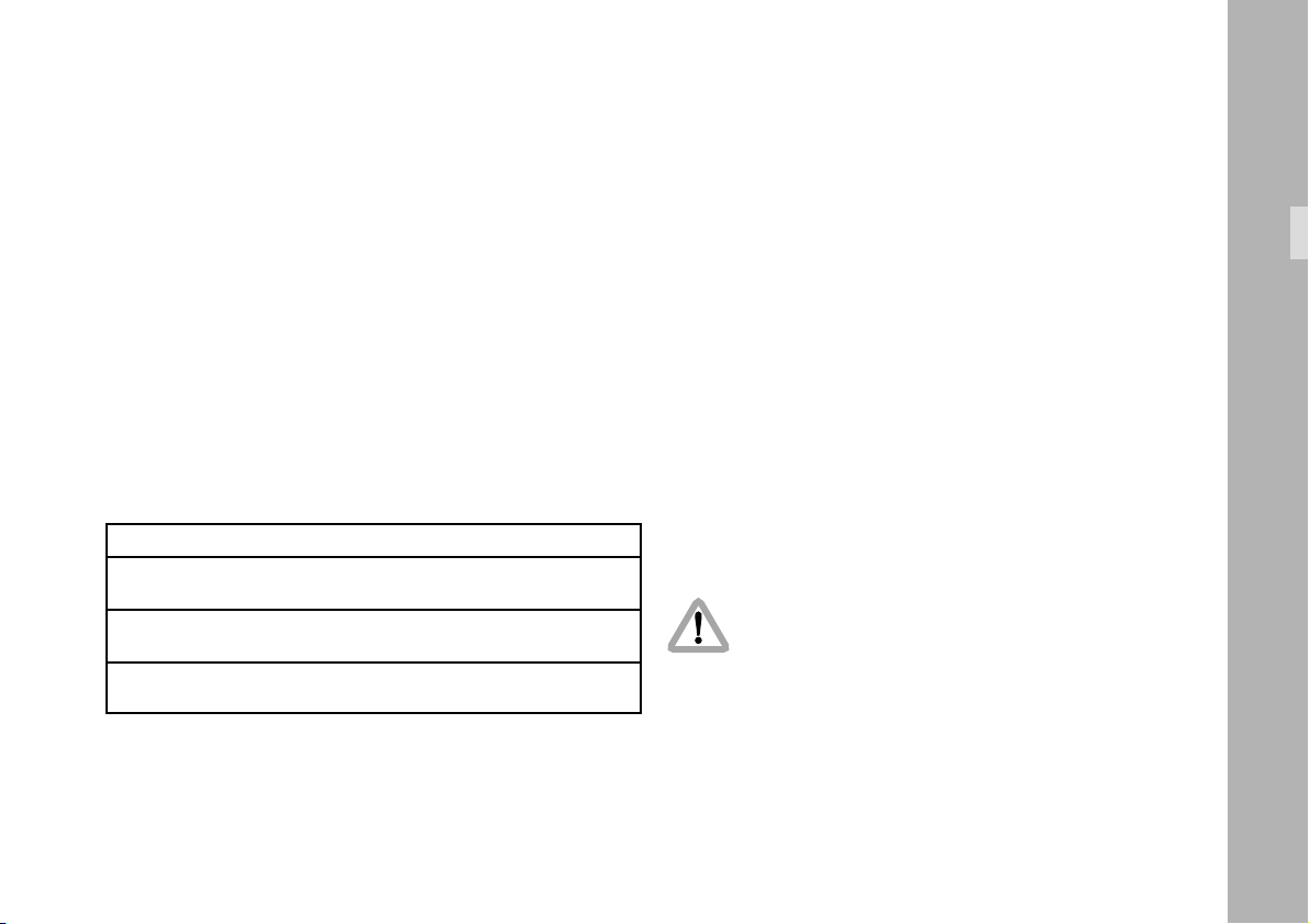
IRIS sliding switch
3.2 Functions
WRC/CAM sliding switch
Functions
SEL button
MODE button
OPEN/PHASE-
button
WRC
rotary switch
handwheel
SET button
RAMP button
COMPENSATION
rotary switch
The WRC/CAM sliding switch is used to select
the operating mode ➪ photo.
3.2.1 CAM mode
In CAM mode, the operator can access the same settings
and modes that are directly available on the camera itself.
The display on the WRC-1 shows the same information as
the camera display.
The MODE, SEL, SET and RAMP buttons have the same
functions as their respective counterparts on the camera.
A RUN LED is also integrated.
In the CAM mode, the OPEN button on the WRC-1 serves
as the PHASE button on the camera.
In CAM mode the WRC-1 serves purely as a camera
remote control unit, without any wider programming options.
The handwheel, the WRC and the COMPENSATION
rotary switches are without function in this operating mode.
12
Page 13

3.2.2 WRC mode
The WRC mode offers convenient programming and easy
adjusting of the camera speed, the shutter angle and the
iris of the lens.
If the iris control is not activated (IRIS sliding switch ‘OFF’),
the OPEN button serves as the PHASE button on the
camera ➪ photo.
The left rotary switch (WRC) ➪ photo is for selecting
the parameter which is to be changed
(master value; for definition, see Glossary):
• camera speed,
• shutter angle or
• iris.
The right rotary switch (COMPENSATION) ➪ photo
is for setting how the change in exposure caused by the
adjustment is to be compensated for
(slave values; for definition, see Glossary).
Example: the WRC rotary switch is set to fps, the COMPENSATION rotary switch is set to Iris. The camera speed is
adjusted with the handwheel, while the WRC-1 automatically
keeps the film exposure constant, adjusting the iris of the
lens.
Depending on the chosen settings and the compensation
method, different ramp times are possible. The minimum
ramp time is calculated by the WRC-1.
Note: The term ‘adjust’ as used in this instruction
manual describes each direct adjustment of a
parameter using the handwheel.
Parallel to this adjustment, the WRC-1 can
automatically compensate the resultant difference
in exposure.
The term ‘ramp’ describes adjustment actions
which automatically take place over a predefined
period of time, i.e. these actions are not directly
controlled using the handwheel. They run continuously for a predefined period of time after
pressing the RAMP button. Resultant differences
in exposure can also be compensated for.
Functions
13
Page 14

3.2.2.1 Overview of the settings available
with the WRC rotary switch
• fps
In the ‘FPS’ mode the camera speed can be adjusted by
turning the handwheel. The end-stops of the handwheel
can be defined by the user within the limits of the attached
camera model.
Functions
(master value: camera speed)
)
•
In the ‘)’ mode the mirror shutter angle can be adjusted
by turning the handwheel. The end-stops of the handwheel
can be defined by the user for the required shutter angle
range.
(master value: mirror shutter angle)
• Iris
In the ‘IRIS’ mode the iris of the lens can be adjusted by
turning the handwheel. The end-stops of the handwheel
can be defined by the user for the required aperture
range.
(master value: iris of the lens)
• ramp fps
In the ‘RAMP FPS’ mode the camera speed is changed
from one value to another over a pre-defined period time.
The speed ramp is started by pressing the RAMP button.
(master value: camera speed + ramp duration)
• ramp
In the ‘RAMP )’ mode the shutter angle is changed from
one value to another over a pre-defined period time. The
shutter angle ramp is started by pressing the RAMP button.
(master value: mirror shutter angle + ramp duration)
• ramp Iris
In the ‘RAMP IRIS’ mode the iris of the lens is changed
from one value to another over a pre-defined period time.
The iris ramp is started by pressing the RAMP button.
(master value: iris of the lens + ramp duration)
)
14
Page 15

3.2.2.2 Overview of the settings available
with the COMPENSATION rotary switch
•off
In the ‘OFF’ position there is no exposure compensation
for the programmed ramp functions or the handwheel
adjustments.
(no slave values)
• Iris
In the ‘IRIS’ position the handwheel adjustments or the programmed ramp functions are compensated for by automatically adjusting the iris of the lens for a constant exposure.
(slave value: iris of the lens)
)
•
In the ‘)’ position the handwheel adjustments or the
programmed ramp functions are compensated for by
automatically adjusting the mirror shutter angle for a
constant exposure.
(slave value: mirror shutter angle)
• Iris / ) 50%
In this mode the exposure compensation is divided equally
between the shutter angle of the camera and the iris of
the lens.
(slave values: iris of the lens + mirror shutter angle)
• max. Iris
In this mode the change in the exposure is compensated for
by the iris of the lens. If the adjustment range of the iris is
not sufficient for the given end values, the remaining rest
will be compensated for by the mirror shutter angle. In this
case, the shutter angle proportion is evenly distributed over
the entire compensation range.
(slave values: iris of the lens + possibly mirror shutter angle)
• max.
In this mode the change in the exposure is compensated for
by the mirror shutter angle. If the adjustment range of the
shutter angle is insufficient for the given end value, the
remaining rest will be compensated for by the iris of the lens.
In this case, the aperture proportion is evenly distributed
over the entire compensation range.
(slave value: mirror shutter angle + possibly the iris of the lens)
• user
With this function ramps can be created which do not
result in constant exposure.
The iris of the lens, the shutter angle and the camera
speed can be combined as required.
)
Functions
15
Page 16
Setup
16
CLM-2
RF
CAL
BAT RDY
RUN
LENS CONTROL SYSTEM
UC-C1
UC-R1
535, 535B, 435, 16 SR3
RS CCU
UMC-1 + URM-1WMU-1 + WRC-1
Page 17

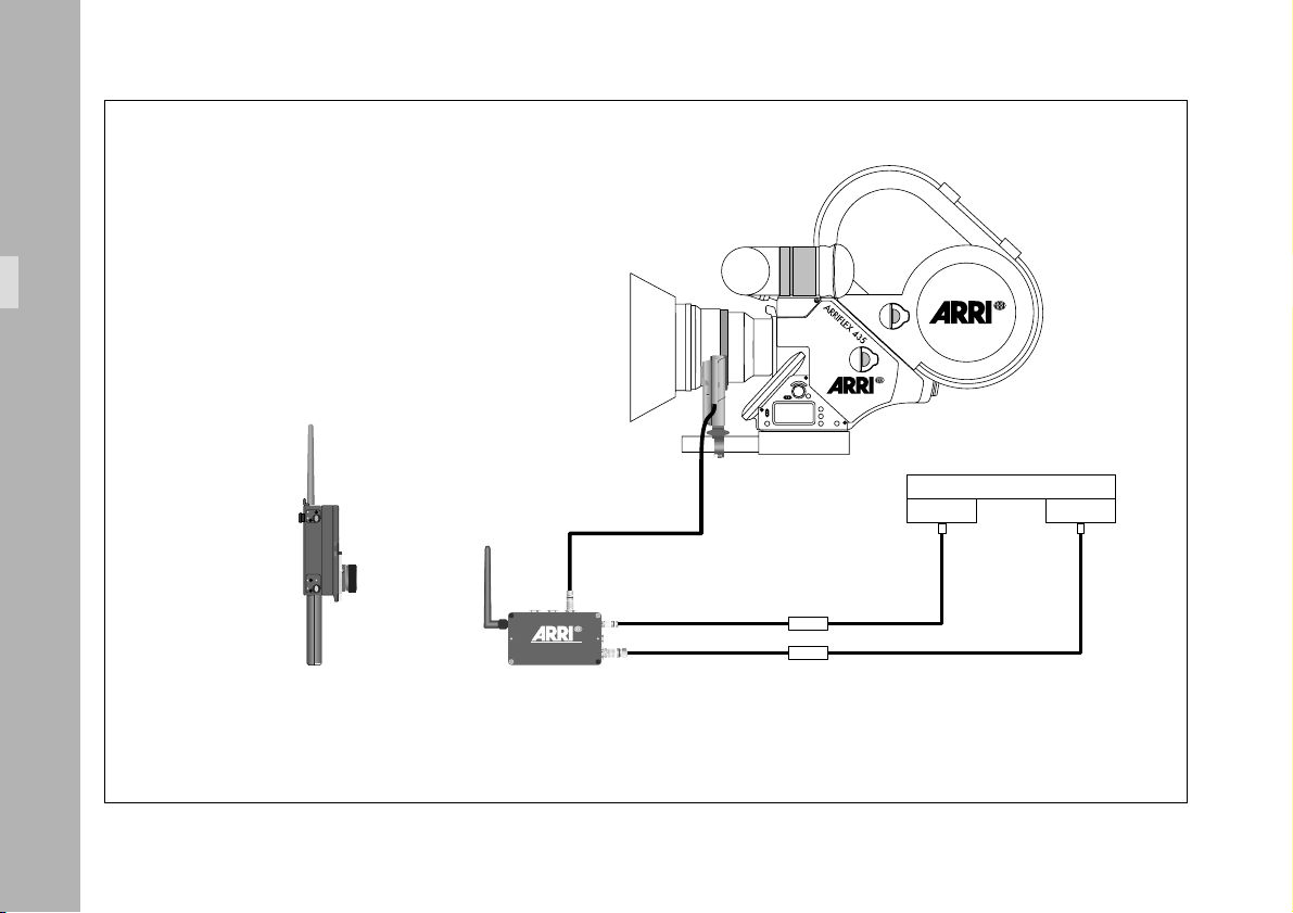
4. Setup
4.1 WRC-1 in wireless mode
In order to be able to use the WRC-1 in wireless mode, it
must be mounted on a Wireless Main Unit (WMU-1). The
Wireless Main Unit supplies the WRC-1 with power and
establishes the radio link with the camera.
An Universal Motor Controller (UMC-1) with an Universal
Radio Module (URM-1) must be mounted on the camera.
The UMC-1 and the URM-1 establish the radio link
outgoing from the camera. A Lens Control Motor CLM-2
for controlling the iris can be connected to the Universal
Motor Controller UMC-1.
For details about setting up the LCS components, refer
also to the LCS instruction manual.
Note: In order to operate the WRC-1 the following
EPROM versions must be used:
WMU-1: 01.50 or higher
UMC-1: 01.50 or higher
ARRIFLEX 435 2.4 or higher
Please contact your nearest ARRI dealer or one of the
service stations to update the EPROMs or to acquire the
latest software version.
Required system components:
WRC-1 .................................................... K2.52087.0
WMU-1 ................................................... K2.52052.0
with WBU-2 battery .................................. K2.52088.0
WAC-1 charger........................................ K2.52072.0
UMC-1 .................................................... K2.52040.0
with UC-C1 cable [K2.52046.0 as replacement]
dovetail adapter ....................................... K2.52080.0
URM-1 ..................................................... K2.52048.0
UC-R1 cable............................................. K2.52079.0
for iris control additionally
CLM-2 ..................................................... K2.52036.0
possibly with console................................. K2.52035.0
Note: CLM-1 motors cannot be used
Setup
as iris motors for the WRC-1!
17
Page 18
Setup
RELEASE button
radio channel
ON button
RF-LED
CAL-LED
CAL button
READY-LED
BAT-LED
RUN-LED
RUN button
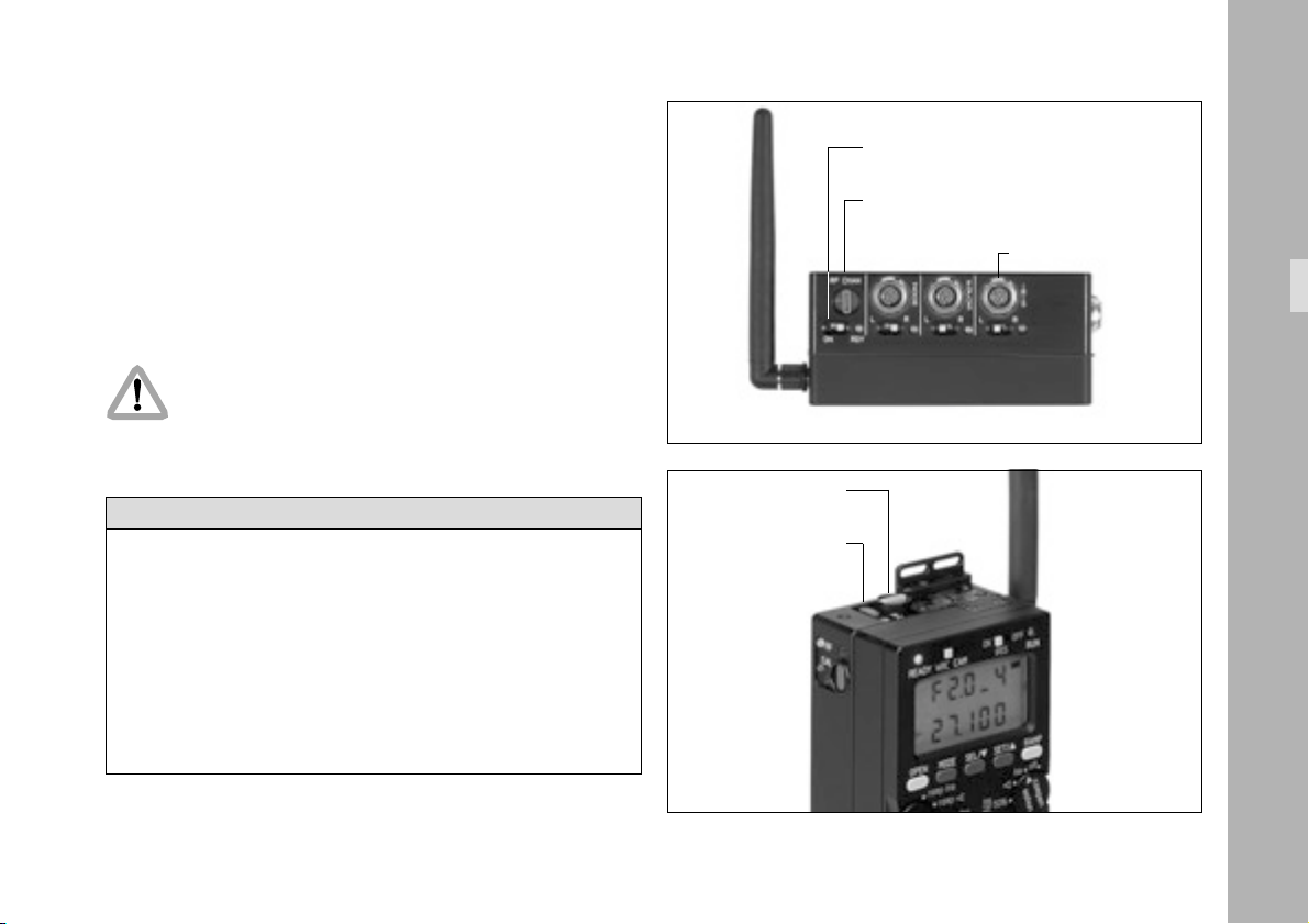
4.1.1 Mounting the WRC-1 on the Wireless Main Unit (WMU-1)
• Switch off the Wireless Main Unit WMU-1 by pressing
the ON/OFF button ➪ photo.
• If an operating unit is already attached, remove it by
pressing the RELEASE button ➪ photo.
Swing out the unit and then remove it by pulling it
upwards.
• With the wide black pin ➪ photo pointing forward,
insert the WRC-1 into the free space on the Wireless
Main Unit WMU-1. Then press the WRC-1 onto the
WMU-1 until the module audibly snaps into position.
Note: The WRC-1 cannot be mounted on a WMU-1
together with other modules.
Note: Do not separate the hand control units from one
another when they are switched on, as this can
result in randomly set lens limits.
18
Page 19
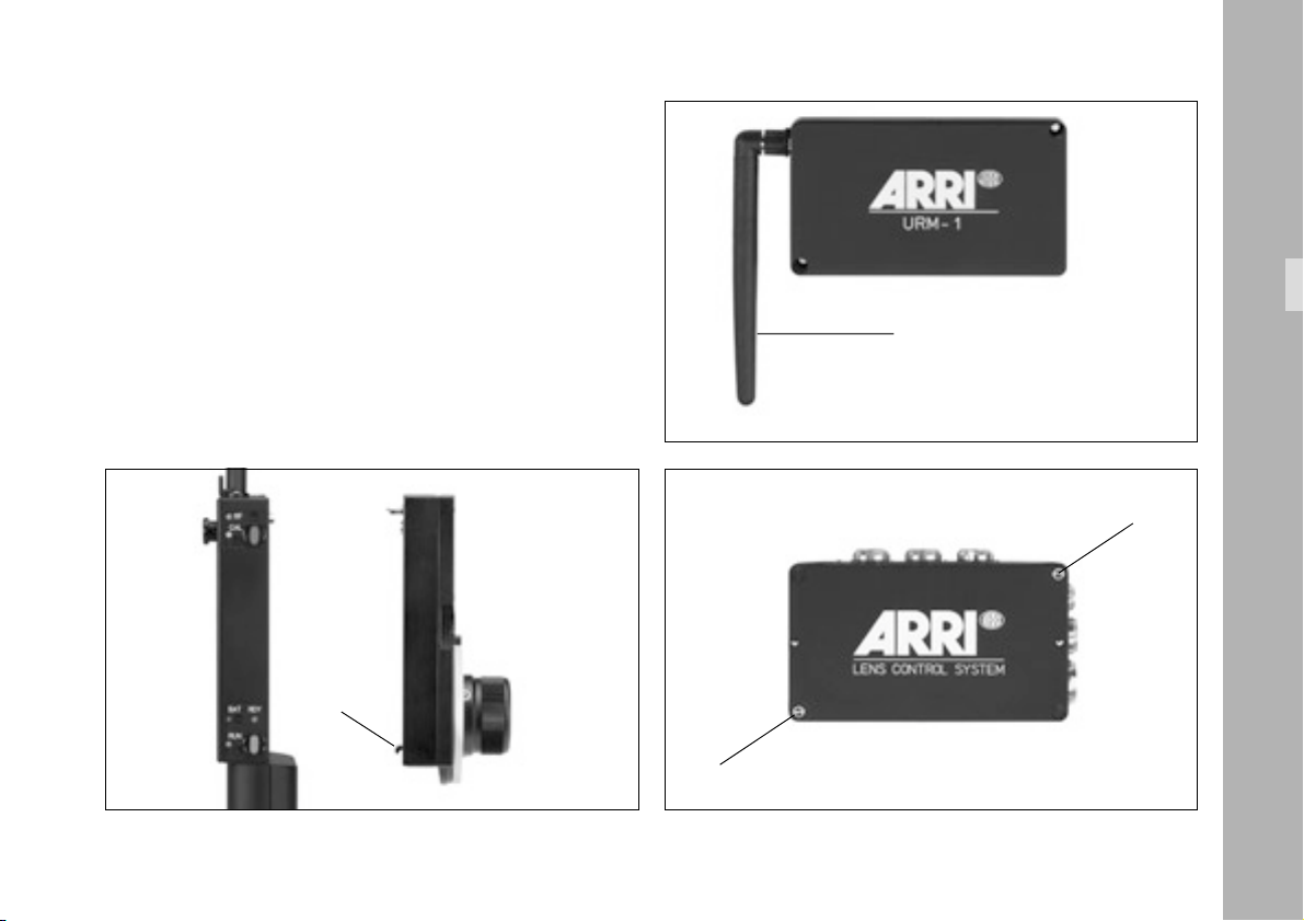
4.1.2 Attaching the UMC-1 and URM-1 to the camera
For wireless operation the UMC-1 must be equipped
with an URM-1.
• Screw the antenna ➪ photo into the threaded
bushing on the URM-1.
• Unscrew the two allen screws ➪ photo from the
cover of the UMC-1 and then remove the cover.
pin
Setup
antenna
allen screw
allen screw
19
Page 20
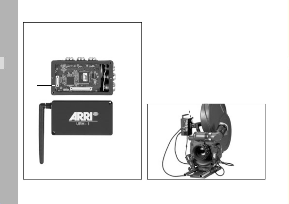
• Place the URM-1 onto the UMC-1, align both plugs
➪ photo with each other and do not tilt them while
attaching.
Setup
plug
• Screw the URM-1 tight to the UMC-1 with the two
allen screws.
• Attach the Universal Motor Controller UMC-1 with the
URM-1 to the camera using the dovetail adapter
➪ photo with a 3/8" threaded bolt (K2.52080.0).
• Connect the RS socket on the camera with the RS
socket on the UMC-1 using the UC-C1 cable.
dovetail adapter
20
Page 21
• Connect the CCU socket on the camera with the CCU
socket on the UMC-1 using the UC-R1 cable.
ON/OFF switch
• Select the same radio channel on the UMC-1 as is set
on the WMU-1 ➪ photo (see LCS Instruction Manual,
chapter 5.1.2.1). If several lenses are to be remotely
controlled independently of each other, the radio
channels 0 and 5, 1 and 6, and 3 and 7 can not be
used simultaneously.
Due to local telecommunications regulations for
the 2.4 GHz band only certain channels are
available sometimes. Only allowed radio
channels must be used.
Switch setting Countries
0 USA, Canada, Mexico, New Zealand, Europe
except France and Spain
1 USA, Canada, Mexico, New Zealand, Europe
except France and Spain
2 Europe except Spain
3 USA, Canada, Mexico, New Zealand, France
4 Japan
5 Australia
6 Australia
7 Spain
8,9 see switch setting 0
• Switch on the UMC-1 using the ON/OFF switch ➪ photo.
radio channel
ON/OFF switch
radio channel
IRIS socket
Setup
21
Page 22
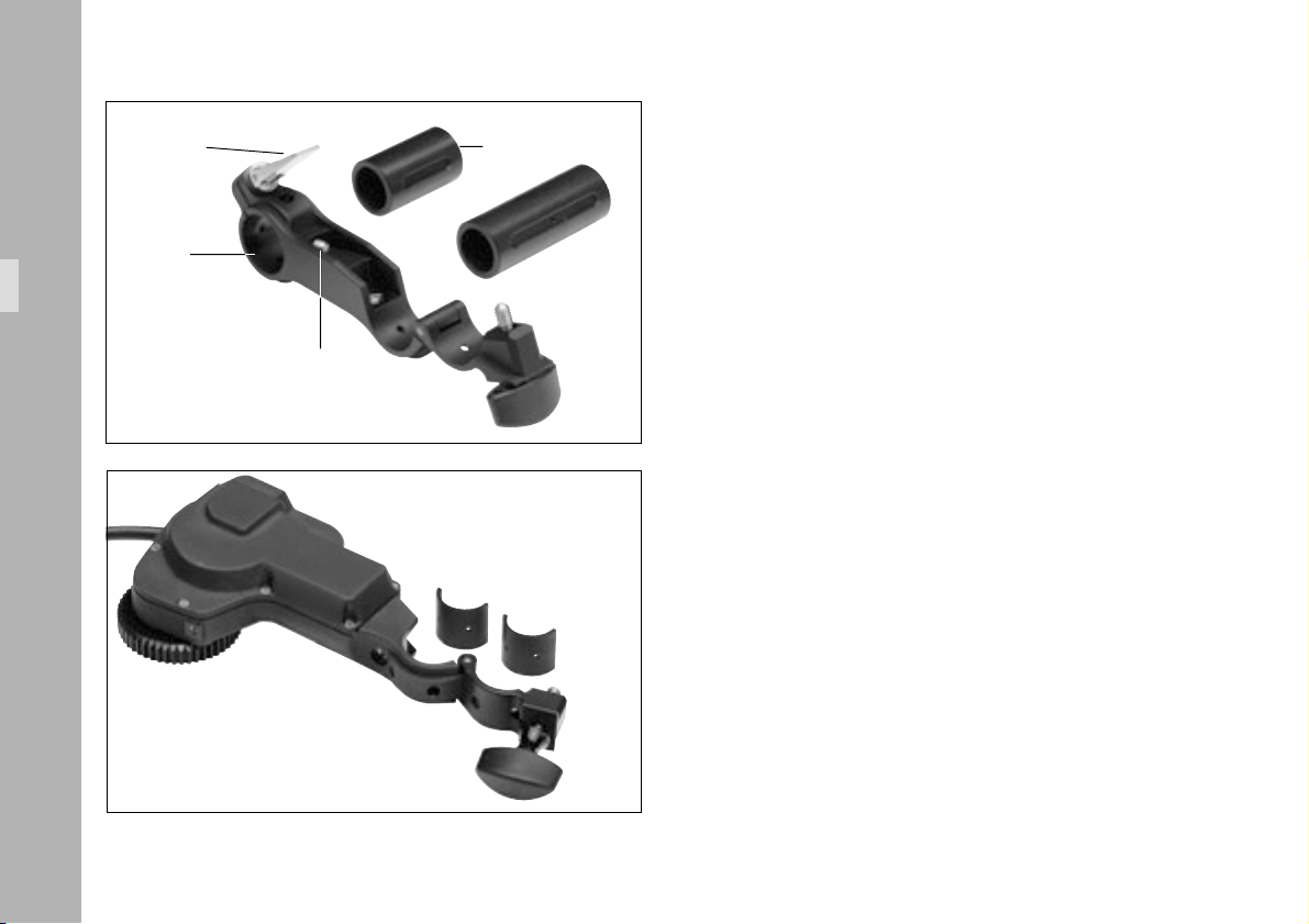
locking lever tube
Setup
receptacle
Setup with Iris control
A CLM-2 motor must be mounted if the iris of the lens is
to be controlled by the WRC-1.
Mounting the CLM-2 motor with/without console
Console order number: K2.52035.0
22
ballcatch
• Flip up the locking lever ➪ photo and screw back
the ballcatch ➪ photo with a screwdriver until it
disappears completely in the bracket.
• Push the tube ➪ photo flush into the console receptacle, taking care that the slit in the tube points towards the ballcatch.
• Screw the ballcatch out of the bracket until the tube
can no longer be pushed out of the bracket.
• Turn the locking lever until a slight resistance can be
felt, then press the lever downwards.
• Fasten the motor unit CLM-2 to the console tube.
Page 23
• Fasten the console to the support rods so that the
motor unit’s drive gear engages with the gear of the
lens ring. Ensure as little play as possible!
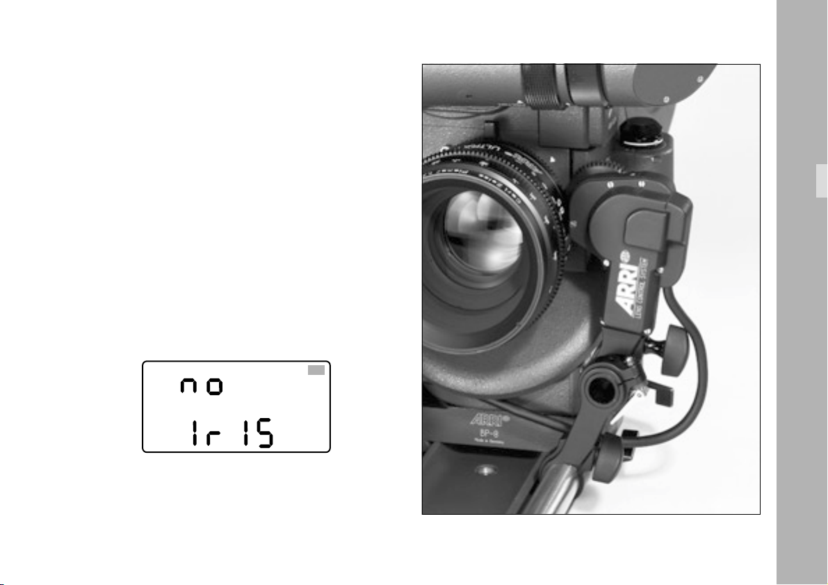
The motor unit CLM-2 can also be mounted directly onto
the support rods without the console.
• Connect the CLM-2 motor to the iris socket of the UMC-1.
Note: All iris-related functions of the WRC-1 are not
available if the CLM-2 motor is not connected. The WRC-1 then displays the ‘NO IRIS’ warning.
Setup
assembly with console
23
Page 24
4.2 WRC-1 in cable mode
Connected with a cable to the camera only those fuctions of
the WRC-1 are available which relate to the camera speed
Setup
and the shutter angle. The iris of the lens cannot be controlled
in the cable mode because the iris motor cannot be accessed.
Required system components:
WRC-1 .................................................... K2.52087.0
WC-W1-S cable ....................................... K2.52089.0
WHA-1.................................................... K2.52070.0
WRC-1
RELEASE button
WHA-1
WC-W1
4.2.1 Mounting the WRC-1 on the
Wireless Handgrip Attachment
(WHA-1)
• If a control unit is already attached remove it by
pressing the release button. Swing out the unit and
then remove it by pulling it upwards.
• Insert the WRC-1 into the available free space on the
WHA-1 (Wireless Handgrip Attachment) with the
wide black pin pointing forward ➪ photo. Then
press the WRC-1 onto the WHA-1 until the module
audibly snaps into position.
• Connect the WHA-1 to the CCU socket of the camera
using the WC-W1-S cable.
black pin
24
Page 25

5. Operation
5.1 Operating modes
5.1.1 CAM mode
The operating elements of the WRC-1 control the same
functions as the corresponding elements on the camera:
MODE, SEL, SET, and the RUN LED. In CAM mode, the
OPEN button corresponds to the PHASE button on the camera.
The RAMP button corresponds to the PROG button on the
camera. The handwheel and the WRC- and COMPENSATION
rotary switches are without function in this operating mode.
• All functions are comprehensively described in the
camera instruction manuals and are not repeated.
The display of the WRC-1 shows the same information as
the camera display in this operating mode.
Note: If the WRC-1 is only to be used in this operating
mode, it is advisable to set the WRC/CAM
sliding switch to CAM before the WRC-1 is
switched on. This ensures that the set frame rate
or a programmed shutter angle in the camera’s
PS/CCU mode and the WRC-1 in WRC mode
is not unintentionally altered.
In WRC mode the WRC-1 overwrites the
camera’s shutter angle and speed settings
(see Important instructions).
Camera programs which have been stored in
the camera via the CCU or the LCC are not
affected.
Forward or reverse run is set in the same way as on the
camera itself.
Note: With the ARRIFLEX 535 forward or reverse run is
set in the same way as on the ARRIFLEX 535B,
435, 16SR 3/Advanced.
Operation
25
Page 26
Operation
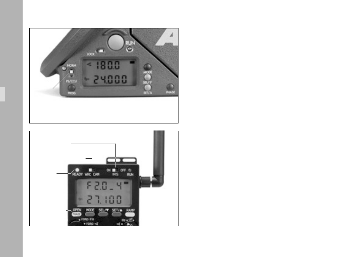
sliding switch NORM / PS/CCU
IRIS sliding switch
WRC/CAM sliding switch
5.1.2 WRC mode
In this mode the WRC-1 offers convenient and quick access
to camera functions and additional programming options.
• Set the sliding switch on the camera from NORM to
PS/CCU ➪ photo.
The display of the WRC-1 flashes with the warning
‘not PSCCU’ until the camera’s sliding switch is set to
PS/CCU.
• Set the WRC/CAM sliding switch to WRC ➪ photo.
• The IRIS sliding switch governs whether the WRC-1
activates its control over the iris motor (IRIS ‘ON’), or
whether a connected iris motor is controlled by
another unit (IRIS ‘OFF’). This must be set before
switching on the WRC-1.
26
READY-LED
OPEN/PHASE-
If the iris control is not activated (IRIS sliding switch
‘OFF’), the OPEN button serves as the PHASE button on
the camera ➪ photo.
Forward or reverse run is set in CAM mode and in the
same way as on the camera itself.
button
Page 27
5.2 Switching on
The WRC-1 does not have its own ON/OFF switch. In
wireless mode it is switched on by pressing the ON button
on the Wireless Main Unit (WMU-1) ➪ photo. In cable
mode it is supplied with power via the cable from the
camera as soon as this is switched on. When in use, the
background of the LCD of the WRC-1 is illuminated as
long as it is active.
The READY LED of the WRC-1 ➪ photo changes from
flashing red to a steady green once the communication
has been established with the camera. The WRC-1 is now
ready for use. In wireless mode the quality of the radio
connection must be read from the RF LED of the Wireless
Main Unit (WMU-1) ➪ photo.
Note: The ZMU must always be switched on first if
cable and wireless units are used together.
The WRC-1 and ICU-1 may not be operated
simultaneously.
READY-LED
ON/OFF
button
RF-LED
Operation
27
Page 28

5.3 Important instructions
• The WRC-1 controls
- the camera speed,
- the mirror shutter angle, and
- the iris of the lens.
All three parameters directly influence the exposure of
the film. In order to avoid unwanted results, and to
prevent the likelihood of incorrect use, all those
parameters controlled by the WRC-1 must be set and
controlled by the user. This also applies when one of
these parameters is not required for the currently
selected remote control: only when all three parameters
have been set (speed, mirror shutter angle and the
aperture) the film exposure is fully defined.
These values are defined separately for each mode,
i.e. the parameters can and must be individually set
for each mode.
Example: first of all a speed ramp is programmed and
Important Instructions
shot. Then only the shutter angle is remotely controlled
for a transition from an outdoor take to an indoor
take. It would not be desirable to continue using those
settings that had been active at the end of the speed
ramp for the next take. Instead, the values set by the
user for the respective modes are active after switching
over to the other mode.
• When operating in WRC mode, the speed or mirror
shutter angle should not be set on the camera itself, as
these are repeatedly written over by the WRC-1. The
WRC-1 is an active unit and its settings have priority
over those of the camera. The camera retains the last
settings sent by the WRC-1 in its memory. This applies
when switching from WRC mode back to CAM mode,
as well as when disconnecting the WRC-1 from the
camera.
• All programmed end-stops and parameters set on the
WRC-1 are stored for as long as required, even when
the unit has been switched off. It is therefore possible
that end-stops for the handwheel had been programmed, which are not available when using this
WRC-1 with another camera model (e.g. high-speed
settings). The WRC-1 recognizes the connected
camera model, but does not independently change the
stored values. If these stored values should lie outside
of the range available for the connected camera
model, a warning is displayed.
28
Page 29

In WRC mode the WRC-1 overwrites the
camera-internal settings for the camera speed
and the mirror shutter angle.
This can result in the following takes being incorrectly exposed if the set values are not checked.
In practice this means, for instance, that the
angle of the mirror shutter set by the WRC-1 is
retained; this also applies when switching back
from PS/CCU to NORM.
The shutter angle is not automatically reset to 180°!
• The WRC-1 and ICU-1 may not be operated simultaneously.
The WRC-1 continuously sends values to the
camera when adjustments are carried out using
the handwheel or during ramp functions. The
radio connection must therefore function perfectly,
otherwise the correct exposure is not ensured.
The user must check that the RF LED is always
on green while the ramp function is running!
• All programs set using the WRC-1 are only stored in
the WRC-1 itself, and not in the camera. The RAMP
function of the WRC-1 therefore is not identical with
the camera’s own program function. It is therfore also
independent of a program which has been stored in
the camera using the CCU or the LCC. These camera
programs cannot be altered using the WRC-1. They
can only be activated and started in CAM mode like
using the operating buttons close to the camera display.
• The ZMU must always be switched on first if cable and
wireless units are used together.
• If a warning is displayed that the compensation limit values cannot be adhered to (readings ‘ANGLE RANGE’, ‘IRIS RANGE’, ‘SPEED RANGE’), while switching over the WRC or the COMPENSATION rotary switches, the end-stops or limit values are still programmed as described. The exceeded values can then be corrected in the relevant submenus.
• All warnings, such as when end-stops or limit values
are exceeded, are only shown in the main menu. The
submenus, on the other hand, are only used to define
all relevant values.
Important Instructions
29
Page 30

• If exposure compensation is not possible with the set
options – e.g. adjusting the iris cannot be compensated
for at the same time by the iris – the WRC-1 displays
the message ‘NO FUNC’ (no function) in the main menu.
The camera can still be run for test purposes
even if the READY LED on the WRC-1 lights up
red or flashes. In this case, however, the
exposure may not comply with the values set in
the in the WRC-1.
• In order to avoid inconstant exposure, all adjustment
processes and ramps under 6 fps are started in the
camera’s dark phase. At these speeds, brief delays of
up to 0.7 seconds at 1 fps may occur until the adjustment or the ramp is started.
• A non-linar phase is integrated into those adjustment
processes and ramps which run at speeds of under
4 fps to avoid inconstant exposures. As a result the
Important Instructions
adjusted parameters do not move continuously.
• In order to operate the WRC-1 the following EPROM
versions must be used:
WMU-1: ........................................ 01.50 or higher
UMC-1:.......................................... 01.50 or higher
ARRIFLEX 435 .................................... 2.4 or higher
Please contact your nearest ARRI dealer or one of the
service stations to update the EPROMs or to acquire
the latest software version.
• As the end-stops of the iris ring on the ARRIMACROS
are changed with the focusing action, the ARRIMACROS
may not be used with the LCS or the WRC-1 system.
30
Page 31

OFFON
IRIS
RAMPSET/SEL/MODEOPEN
RUN
CAM
WRC
READY
PHASE
,Iris
WRC-1
fps,
Iris
user
max
max
Iris
50%
Iris
off
Iris
fps
fpsramp
ramp
ramp Iris
PROG
compen
sation
WRC
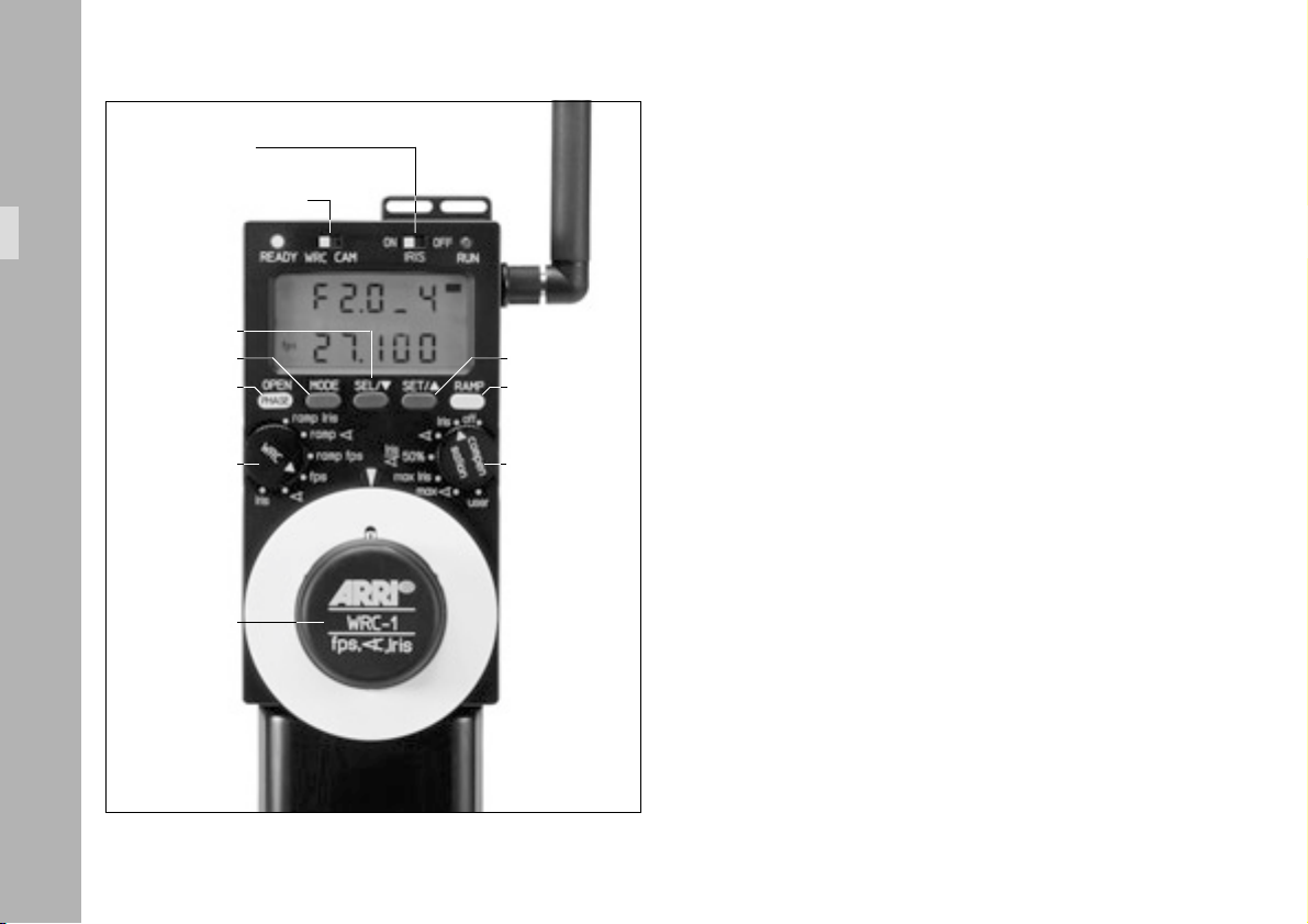
5.4 Using the menus
5.4.1 Main menu
The main menu is indicated by a black bar in the top
right corner of the display ➪ photo. The currently
adjusted value and the value of one of the two possible
exposure compensations are shown in the display.
If PROG is also displayed ➪ photo, a time-controlled
ramp function (ramp Iris, ramp ), ramp fps) has been
selected using the WRC rotary switch. In this mode the
handwheel is without function in the main menu, as the
ramp is started with the RAMP button. In the three other
WRC rotary switch positions (fps, ), Iris) a parameter
can be adjusted directly using the handwheel. The display
shows the respective value and an automatically generated
compensation value.
Note: All warnings, such as when end-stops or limit
values are exceeded, are only shown in the
main menu. The submenus are only used to
define all relevant values.
black bar
PROG symbol
Using the menus
handwheel
31
Page 32

Iris
,Iris
max
IRIS
50%
Iris
max
OFFON
Iris
sation
CAM
WRC
READY
MODE button SET button
PHASE
ramp Iris
ramp
WRC
Using the menus
Iris
fpsramp
fps
WRC-1
fps,
RUN
RAMPSET/SEL/MODEOPEN
off
compen
user
Note: If exposure compensation is not possible with
the set options – e.g. adjusting the iris cannot
be compensated at the same time by the iris –
the WRC-1 displays the message ‘NO FUNC’
(no function) in the main menu.
In the main menu limit values, end-stops for the handwheel
(definition: see Glossary or 5.4.2.1 Limit values), or fixed
values (definition: see Glossary or 5.4.2.2 Fixed values
below) for the exposure cannot be pre-set. The main
menu valid for each operating mode is explained later on
with the respective mode.
• By pressing the SET button values that are currently not
displayed can be checked, e.g. the current shutter angle
and the camera speed can be checked in the iris main
menu.
• Press the MODE button to change from the main menu
to the submenus. Press the MODE button again to enter
the next submenu until the main menu mode reappears.
The submenu sequence can vary according to the operating modes selected using the WRC- and COMPENSATION
rotary switches.
32
Page 33

5.4.2 Submenus
The submenus are used to define the end-stops of the
handwheel and all relevant limit and fixed values.
The value in the first line of the display corresponds to the
left handwheel end-stop or the start value of the ramp.
The value in the second line of the display corresponds to
the right handwheel end-stop or the end value of the ramp.
5.4.2.1 Limit values
A so-called limit value is either the left or the right end-stop
of the handwheel, or the start and end value of a timecontrolled ramp.
The limit values for the master value are always defined in
the first submenu.
• Defining the handwheel’s end-stops:
If a function has been selected using the WRC rotary
switch which provides remote control with the handwheel
(Iris, ), fps), the two values for the left and the right
handwheel end-stop are defined in the first submenu.
• Defining the start and end values of a ramp:
If a function has been selected using the WRC rotary
switch which controls a program over a pre-defined
period of time (ramp Iris, ramp ), ramp fps), the start
and end values of the ramp are defined in the first
submenu; e.g. the start and the end speed in the case
of a speed ramp.
5.4.2.2 Fixed values
The remaining parameters for the film exposure are defined
in the following submenus. Example: If the camera speed
has been selected as the parameter to be adjusted, the
shutter angle and the aperture of the lens must be defined
in the next submenus, if they are controlled by the WRC-1.
If a ramp function has been selected, the duration of the
ramp must also be entered.
Note: Multiple limit values are defined if changes in
exposure are automatically compensated for –
example: Iris compensated with the shutter angle;
the aperture of the lens alters during the adjustment (master value) and the shutter angle is
adjusted automatically as a compensation. One
of the two limit values for the shutter angle can be
assigned; the other limit value is automatically
calculated by the WRC-1. It must be ensured
that the available adjustment range is not
exceeded.
Using the menus
33
Page 34

READY
WRC
CAM
IRIS
PROG
• Press the MODE button to change from the main menu
to a submenu. Each further press of the MODE button
takes the user to the next submenu, until the main
menu mode reappears.
OFFON
RUN
• In a submenu press the SEL button for longer than 2
seconds to activate the edit mode, in which values can
be defined.
SEL button SET button
PHASE
ramp Iris
ramp
WRC
Iris
fpsramp
fps
Using the menus
WRC-1
fps,
34
Iris
,Iris
max
50%
Iris
max
RAMPSET/SEL/MODEOPEN
off
Iris
compen
sation
user
• The flashing digits can be edited using the handwheel.
• By pressing the SEL button the adjusted value is stored
and the next digits are activated. After the last digit
has been entered the edit mode is exited.
If only plain figures are to be adjusted, the decimal positions
can easily be set to ‘0’ by pressing the SET button. The
values for the next line can then be entered.
handwheel
The submenus cannot be edited while the camera is running.
Page 35

Using the menus
35
Page 36

Iris
comp. off
Iris
comp.
Iris
<
)
comp. user
ramp Iris
comp. off
ramp Iris
comp. <)
ramp Iris
comp. user
fps
fps
fps
fps
Controlling the Iris
PROG
PROG
fps
PROG
PROG
fps
PROG
PROG
PROG
PROG
PROG
fps
fps
PROG
PROG
PROG
PROG
PROG
PROG
PROG
36
Page 37

OFFON
IRIS
RAMPSET/SEL/MODEOPEN
RUN
CAM
WRC
READY
PHASE
Iris
max
Iris
50%
Iris
off
fps
fpsramp
ramp
ramp Iris
PROG
compen
sation
WRC
5.5 Controlling the iris (master value: Iris)
If the aperture of the lens (iris) is to be controlled by the
WRC-1, a lens motor CLM-2 must be mounted on the
camera and connected to the UMC-1/URM-1.
Note: The iris can only be adjusted using CLM-2 motors.
If a CLM-1 motor is used the warning ‘NO IRIS’
is displayed.
When switching on the WRC-1, the IRIS sliding switch ➪
photo is used to determine whether the WRC-1 (‘IRIS ON’)
or another unit (e.g. a WFU-1) (‘IRIS OFF’) controls the
connected iris motor.
• The IRIS sliding switch must be set to ‘ON’ before
turning on the WRC-1.
IRIS sliding switch
Controlling the Iris
If the IRIS sliding switch is not set to ‘ON’ and an operating mode is selected, which requires an iris motor, the warning ‘NO IRIS’ is displayed. This warning is also displayed if the IRIS sliding switch is set to ‘ON’ although a CLM-2 motor has not yet been connected. In this case the CLM-2 motor must be connected to the IRIS socket on the UMC-1.
37
Page 38

First the end-stops of the lens must be calibrated and the
engraved T-stops must be assigned in the WRC-1 (as
described below) for each lens being used.
As the end-stops of the iris ring on the
ARRIMACROS change when the lens is focussed,
the ARRIMACROS may not be used with the
LCS or the WRC-1 system.
5.5.1 Assigning the T-stops
The adjustable T-stops (1, 1.4, 2, 2.8, 4, 5.6, etc.) must be
correctly assigned in the WRC-1 to the various positions
engraved on the iris ring of the lens. The iris cannot be
remotely controlled until the respective positions have been
assigned. This assignment is stored in the WRC-1 in a
table (tbl).
Before assigning the T-stop values and calibrating
the end-stops of the iris ring of the lens, check
all the motors you want to use to be firmly
attached to the support rods of the bridge plate.
Controlling the Iris
38
• If a lens has not yet been selected and the T-stops have not yet been assigned (condition on delivery from the factory, or the active iris table has been deleted from the memory), a flashing warning appears – ‘IRIS TBL’ – when the WRC-1 is switched on with the IRIS sliding switch set to the position ‘ON’. Press the MODE button once to enter the input mode.
• If a lens has already been selected and T-stops have
been assigned previously, the menu for programming
the T-stops of the iris is always the last submenu before
returning to the main menu in the WRC rotary switch
position ‘IRIS’.
Press the MODE button three times in the WRC rotary
switch position ‘IRIS’ and the COMPENSATION rotary
switch at ‘OFF’ until ‘TBL LOAD’ appears on the display.
Page 39

Note: Depending on the selected function and com-
pensation, this input menu can also be found in
other relevant positions by repeatedly pressing
the MODE button.
In the table submenu, it is possible to:
• load factory- and user-defined iris tables, menu option ‘TBL LOAD’,
• delete iris tables from the active memory (factory- or user-defined iris tables are not deleted), menu option ‘TBL DEL’,
• edit iris tables, menu option ‘TBL EDIT’, or
• store user-defined iris tables on one of the 10 available memory areas. menu option ‘TBL STORE’.
• The required function is selected using the handwheel
and then activated by pressing the SEL button.
For the Zeiss Ultra Primes, the Variable Primes, the Highspeed set, and the Standard set iris tables are already
programmed in the WRC-1. For other lenses iris tables
can be stored.
10 memory areas are available.
The values of the last lens used may still be
active and stored in the WRC-1.
All settings and the active iris table should
therefore always be checked in order to avoid
incorrect exposures!
Controlling the Iris
39
Page 40

Controlling the Iris
5.5.1.1 Loading iris tables for Zeiss Ultra Primes,
Variable Primes, High-speed, Standard or
user-defined lenses
(‘TBL LOAD’)
The iris tables for the factory pre-defined lenses
require that a standard gear ring is used on the
lens motor (50 teeth). If other gear rings are used,
the T-stop scale must be completely programmed
from scratch. This also applies if a gear adapter
ring is used with the lens.
The pre-defined iris tables are loaded as follows:
• If ‘IRIS TBL’ flashes on the display when the WRC-1 is
switched on, the MODE button must be pressed once
to enter the ‘TBL LOAD’ mode.
If a lens has already been selected and the T-stops
have been assigned previously, the menu for selecting
the lens can be entered in the WRC rotary switch
position ‘IRIS’ and the COMPENSATION rotary switch
set to ‘OFF’ by pressing the MODE button three times.
• Then press the SEL button. The lens type is shown in
the first line of the display.
40
Page 41

Pre-defined lens types are:
Display: Lens set:
UP ARRI Zeiss Ultra Primes
VAr P ARRI Zeiss Variable Primes
HS 35 ARRI Zeiss High-speed lenses for 35mm film
Std35 ARRI Zeiss Standard lenses for 35mm film
HS 16 ARRI Zeiss High-speed lenses for 16mm film
User lens previously defined by the user
• Select the required lens set using the handwheel.
Then press the SEL button. The focal length then
appears in the second line of the display.
• Select the focal length using the handwheel.
Confirm the selection by pressing the SEL button.
• The display now shows the command ‘DO CAL’. Start the calibration by pressing the CAL button on the WMU-1 ➪ photo.
Controlling the Iris
CAL button
41
Page 42

Controlling the Iris
•‘ADJ’ now flashes in the first line of the display.
A T-stop value is shown in the second line.
• Adjust the iris ring to the displayed value using the
handwheel.
• The T-stop is assigned by pressing the SET button.
This is indicated in the first line with an ‘I’ next to ‘TBL’.
This defines the entire iris table.
‘DONE’ is shown on the display for one second.
• The display then shows ‘TBL’ in the first line,
and the letter ‘F’ and a T-stop value in the second line.
The individual T-stops available for this lens must now
be checked using the handwheel!
An ‘I’ is shown in the first line of the display next to
‘TBL’ for every T-stop programmed for this lens.
Note: Only full T-stops are accessible for checking to
speed up the process in this mode.
After loading the iris table, all individual T-stops
on the lens must be checked by adjusting with
the handwheel in order to avoid incorrect
exposures!
42
Page 43

• Press the MODE button to go back to the table menu
(TBL LOAD, TBL DEL, TBL EDIT, TBL STORE).
• To go back to the main menu press of the MODE button
again.
Controlling the Iris
43
Page 44

Controlling the Iris
5.5.1.2 Programming an iris table for other lenses (‘TBL EDIT’)
• If ‘IRIS TBL’ flashes on the display when the WRC-1 is
switched on, the MODE button must be pressed once
to enter the ‘TBL LOAD’ mode.
If a lens has already been selected and the T-stops
have been assigned previously, the menu for selecting
the lens can be entered in the WRC rotary switch
position ‘IRIS’ and the COMPENSATION rotary switch
set to ‘OFF’ by pressing the MODE button three times.
The values for the last lens used may still be stored
and active in the WRC-1. All settings and the
active iris table should therefore always be
checked in order to avoid incorrect exposures!
• To delete an old assignement (iris table), turn the
handwheel until ‘DEL’ is shown in the second line of
the display. Then press the SEL button. ‘TBL’ flashes in
the first line. Press the SET button to finally delete the
old assignement. ‘DONE’ is shown on the display for
one second.
44
Page 45

• Press the CAL button on the WMU-1 to start the
calibration process before entering any values.
• Turn the handwheel until ‘TBL EDIT’ is displayed.
Press the SEL button to go to the input mode.
• Turn the handwheel to the left until the first T-stop of
the iris ring of the lens being used is shown in the
second line of the display.
This must be a full T-stop from the standard T-stop
range.
• Then press the SEL button. ‘ADJ’ now flashes in the
first line of the display.
• Adjust the iris ring of the lens to the displayed value
using the handwheel.
• The T-stop is assigned by pressing the SET button. This
is indicated in the first line with an ‘I’ next to ‘TBL’.
• In case you need to delete this assignment, press the
SET button again. The ‘I’ next to ‘TBL’ disappears again.
• Turn the handwheel until the next T-stop on the iris ring
of the lens being used is shown on the display. Assign
this and the next T-stops as described above.
Controlling the Iris
45
Page 46

Note: If the T-stop scale of the lens being used is linear,
it is sufficient to enter just two T-stops, which must
be at least four T-stops apart, in order to define
the iris table. If the T-stop scale is not linear, all
the T-stops must be assigned individually.
After programming the iris table, all individual
T-stops on the lens must be checked by adjusting
with the handwheel in order to avoid incorrect
exposures!
Note: If the lens has a CLOSE position, this must also
be defined, as the iris table only applies up to
the last value before the CLOSE position! When
assigning, the CLOSE position is programmed
after the highest possible T-stop setting.
Controlling the Iris
Note: For compensating the exposure, only the range
between full T-stops may be used! Example: the
iris scale of the lens reaches from T2.2 to 22.
The values for T4 and T16 are assigned. The
resulting usable range reaches from T2.8 to
T22, as T2.2 is not a T-stop from the standard
T-stop range (T2.0).
Note: If a T-stop value has been assigned which
cannot be correct, a warning is displayed; e.g.
T-stop 11 cannot lie between 5.6 and 8. The
incorrectly positioned value must be deleted.
If the iris table should remain available after using
another lens, it must be stored as described below. This
also applies when an iris table has been re-edited.
46
Page 47

5.5.1.3 Storing an iris table
(‘TBL STORE’)
After assigning the T-stops the resulting iris table can be
stored for later use.
• Press the MODE button in the submenu for assigning
the T-stops to go back to the table menu (TBL LOAD,
TBL DEL, TBL EDIT, TBL STORE).
• Turn the handwheel until ‘STORE’ is shown in the
second line.
• Press the SEL button. ‘STORE’ is displayed in the first line, and the number of the memory area is shown in the second line.
• Select the number of the required memory area using
the handwheel. 10 memory areas are available.
When storing, existing table data in this
memory area are overwritten without warning!
• The iris table is stored by pressing the SEL button.
‘DONE’ is displayed for one second.
• Note down the number of the memory area together
with the programmed lens to simplify activating lenses
at a later time.
Controlling the Iris
47
Page 48

Controlling the Iris
5.5.1.4 Loading a user-defined iris table
(‘TBL LOAD’)
• If ‘IRIS TBL’ flashes on the display when the WRC-1 is
switched on, the MODE button must be pressed once to
enter the ‘TBL LOAD’ mode.
If a lens has already been selected and the T-stops have
been assigned previously, the menu for selecting the
lens can be entered in the WRC rotary switch position
‘IRIS’ and the COMPENSATION rotary switch set to
‘OFF’ by pressing the MODE button three times.
• Turn the handwheel until ‘LOAD’ is displayed in the
second line; confirm the selection by pressing the SEL
button.
• Select ‘USER’ with the handwheel. Then press the SEL button. The required memory area can be selected in the second line using the handwheel (see Chapter
5.5.1.2 Storing an iris table, directly preceding this
chapter).
• Confirm the selection by pressing the SEL button.
• The display now shows the command ‘DO CAL’.
Start the calibration process by pressing the CAL
button on the WMU-1.
48
Page 49

The WRC-1 is not able to check whether the
selected user-defined iris table is actually
compatible with the lens being used. An error
message can only be displayed if the iris motor
reaches the end-stops of the lens during calibration, and these had been positioned elsewhere while the lens was being programmed.
• If the wrong iris table has been unintentionally selected (e.g. by choosing the wrong memory area), and the iris motor strikes unexpected end-stops during the calibration process, the warning ‘LENS ERROR’ is displayed. Press the SEL or SET button to go to the mode for assigning the T-stops. The current T-stops can be reassigned.
CAL button
ft
m
h:min
TC UB
R
fps end
sec:f bat
312 4
8765
PROG
filter
jam
asy
Controlling the Iris
49
Page 50

Controlling the Iris
• If the lens has been successfully calibrated, ‘ADJ’
flashes in the first line of the display.
A T-stop value is shown in the second line.
• Adjust the iris ring of the lens to the displayed value
using the handwheel.
• The T-stop is assigned by pressing the SET button.
This is indicated in the first line with an ‘I’ next to ‘TBL’.
This defines the entire iris table. ‘DONE’ is displayed
for one second.
• The display then shows ‘TBL’ in the first line,
and the letter ‘F’ and a T-stop value in the second line.
All individual T-stops must be checked by adjusting
with the handwheel! An ‘I’ is shown in the first line of
the display next to ‘TBL’ for every T-stop assigned for
this lens.
After loading the iris table, all individual T-stops
on the lens must be checked by adjusting with
the handwheel in order to avoid incorrect
exposures!
• Press the MODE button to go back to the table menu
(TBL LOAD, TBL DEL, TBL EDIT, TBL STORE). To go back
to the main menu press of the MODE button again.
50
Page 51

Note: If a previously programmed iris table is re-edited,
the corresponding table must first be loaded
from its memory area as described above.
The handwheel must then be turned in the table
menu (TBL LOAD, TBL DEL, TBL EDIT, TBL STORE)
until ‘EDIT’ is displayed in the second line.
Confirm with the SEL button to return to the edit
mode for this table.
5.5.1.5 Important instructions for programming the iris of the lens
• If the lens has a CLOSE position, this must also be defined,
as the iris table only applies up to the last value before
the CLOSE position! When assigning, the CLOSE position
is programmed after the highest possible T-stop setting.
from T2.8 to T22, as T2.2 is not a T-stop from the
standard T-stop range (this would be T2.0, for example).
• The display shows full T-stops followed by the tenth of
a T-stop. Example: T-stop 2.8 plus half a T-stop is
shown as 2.8_5. The tenths of a T-stop are linearly
divided between the two full T-stop positions.
• To check the image in the viewfinder, the iris can be
opened completely by pressing the OPEN button. The
iris remains open until the OPEN button is released
again. This does not alter the programmed settings.
The OPEN button is without function while the camera
is running.
• If the T-stop scale of the lens being used is linear, it is
sufficient to enter just two T-stops, which must be at
least four T-stops apart, in order to define the iris
table. If the T-stop scale is not linear, all the T-stops
must be assigned individually.
• For compensating the exposure, only the range between
full T-stops may be used! Example: the iris scale of the
lens reaches from T2.2 to 22. The values for T4 and
T16 are assigned. The resulting usable range rechaes
Controlling the Iris
51
Page 52

Iris
comp. off
fps
Controlling the Iris
5.5.2 Iris / compensation off
The iris can be manually adjusted within the pre-defined
end-stops of the handwheel.
Differences in exposure are not automatically
compensated for.
The main menu shows ‘IRIS’ in the first display line, and
the currently adjusted T-stop in the second line.
The display shows full T-stops followed by the tenth of a
T-stop. Example: T-stop 2.8 plus half a T-stop is shown as
2.8_5. The tenths of a T-stop are linearly divided between
the two full T-stop positions.
Note The following warnings may be displayed:
‘IRIS TBL’ – a valid iris table has not yet been
activated;
readings with ‘NO’ in the first display line
indicate that the selected function is currently
not available (example: ‘NO IRIS’ although the
iris control is activated on the WRC-1, the iris
motor has not yet been connected);
readings with ‘RANGE’ in the second display
line indicate that the adjustment range of a
parameter has been exceeded (example: the
52
Page 53

selected speed cannot be attained with this
camera). Correct parameters must be set before
the camera is started!
Note: To check the image in the viewfinder, the iris
can be opened completely by pressing the
OPEN button. The iris remains open until the
OPEN button is released again.
This does not alter the programmed settings.
The OPEN button is without function while the
camera is running.
With the iris wide open a lens-related reduction
in brightness towards the edge of the image
may occur, looking like an incorrect exposure.
The exact values are dependent on the lens type
and must be determined with test shots.
• Press the MODE button in the main menu to enter the
first submenu. The left and right end-stop for the handwheel (minimum and maximum aperture) can be defined.
The first display line shows the value for the left end-stop,
the second line shows the value for the right end-stop.
By pressing the SET button the currently set shutter angle
(if controlled by the WRC-1) can be shown in the first
display line. The currently set camera speed is shown in
the second display line.
With most lenses, the T-stops before the end-stops
are not exact due to the tolerances involved. In
order to avoid incorrect exposure, the adjusted
iris range should not contain these values.
• Press the SEL button for longer than 2 seconds. The T-stop
value in the first display line flashes. The required value
can now be adjusted using the handwheel.
Press the SEL button again to switch to the next digit.
The first digits are confirmed, and the decimal is set to
‘0’ by pressing the SET button. The values in the
second display line can be set accordingly.
• Press the MODE button to go to the next submenu.
To define the fixed values for the mirror shutter angle
(if controlled by the WRC-1), and the camera speed,
use the SEL and SET buttons and the handwheel, as
described above.
Controlling the Iris
53
Page 54

• Press the MODE button to enter the next submenu. The
table menu has already been described under 5.5.1.
• Press the MODE button to go back to the main menu.
Controlling the Iris
fps
Iris
comp.
<
)
54
Page 55

5.5.3 Iris /
compensation shutter angle
The iris can be manually adjusted within the pre-defined
end-stops of the handwheel (master value: Iris).
The exposure is automatically compensated for with the
mirror shutter angle. The visible depth of field can be
altered with this function.
The first line of the main menu shows the shutter angle,
which is automatically calculated within the pre-defined
limits. The second line shows the currently adjusted T-stop
of the lens using the handwheel.
The display shows full T-stops followed by the tenth of a
T-stop. Example: T-stop 2.8 plus half a T-stop is shown as
2.8_5. The tenths of a T-stop are linearly divided between
the two full T-stop positions.
Note The following warnings may be displayed:
‘IRIS TBL’ – a valid iris table has not yet been
activated;
readings with ‘NO’ in the first display line
indicate that the selected function is currently
not available (examples: ‘NO IRIS’ although the
iris control is activated on the WRC-1, the iris
motor has not yet been connected. The connected
camera does not have an electronically adjustable
mirror shutter);
readings with ‘RANGE’ in the second display line
indicate that the adjustment range of a parameter
has been exceeded (example: the selected speed
cannot be attained with this camera);
readings with ‘OFF’ in the first display line
indicate that this function is deactivated on the
camera (example: shutter angle of the 435 is
set manually = ‘OFF ANGLE’).
Correct parameters must be set before the
camera is started!
Note: To check the image in the viewfinder, the iris
can be opened completely by pressing the
OPEN button.
The iris remains open until the OPEN button is
released again.
This does not alter the programmed settings.
The OPEN button is without function while the
camera is running.
By pressing the SET button the currently set camera speed
can be shown in the second display line.
Controlling the Iris
55
Page 56

With most lenses, the T-stops before the end-stops
are not exact due to the tolerances involved. In
order to avoid incorrect exposure, the adjusted
iris range should not contain these values.
With the iris wide open a lens-related reduction
in brightness towards the edge of the image
may occur, looking like an incorrect exposure.
The exact values are dependent on the lens type
and must be determined with test shots.
Controlling the Iris
• Press the MODE button in the main menu to enter the
first submenu. The left and right end-stop of the handwheel
(minimum and maximum aperture) can be defined.
The first display line shows the value for the left end-stop,
the second line shows the value for the right end-stop.
• Press the SEL button for longer than 2 seconds.
The T-stop value in the first display line flashes.
The required value can now be adjusted using the
handwheel. Press the SEL button again to switch to the
next digit. The first digits are confirmed, and the decimal
is set to ‘0’ by pressing the SET button. The values in
the second display line can be set accordingly.
If the compensation range available with the
shutter angle is exceeded, the warning ‘ANGLE
RANGE’ flashes on the display after returning
to the main menu. The settings for the iris or the
shutter angle must be corrected accordingly!
The camera can still be started for test purposes
in spite of the flashing warning. However, the
exposure may be incorrect!
56
Page 57

• Press the MODE button to go to the next submenu.
The limit values for the shutter angle can be defined:
The shutter angle is automatically adjusted to compensate the exposure while the iris is adjusted with the
handwheel. One of the two limit values (minimum or
maximum shutter angle, depending on the adjustment
direction of the iris) can be defined; the other limit
value is automatically calculated by the WRC-1.
• Press the SEL button for longer than 2 seconds.
Depending on the definable limit value, the first digits
flash in the first or second display line.
These can now be adjusted using the handwheel.
The automatically calculated other limit value is shown
in the other display line.
Press the SEL button again to switch to the next digit.
The first digits are confirmed, and the decimal is set to
‘0’, by pressing the SET button.
The minimum shutter angle corresponds to the selected
maximum aperture (smallest T-stop number).
• Press the MODE button to go to the next submenu.
The fixed value for the camera speed is defined using
the SEL and SET buttons and the handwheel.
• Press the MODE button to enter the next submenu. The
table menu has already been described under 5.5.1.
• Press the MODE button to go back to the main menu.
Controlling the Iris
57
Page 58

Iris
comp. user
fps
fps
Controlling the Iris
5.5.4 Iris / compensation user
Using the handwheel, the iris can be manually adjusted
within the user-defined end-stops, simultaneously together
with the values for the shutter angle and the camera speed.
If appropriate values are selected, either the exposure can
be kept at a constant level, or an adjustment process can
be defined to change the exposure as required (e.g.
fading in or out).
Note: The function of the user mode always remains
the same, irrespective of the position of the WRC
rotary switch (Iris, ) or fps): The timing of the
simultaneous adjustment processes is controlled
using the handwheel. If a ramp function is
selected (ramp Iris, ramp ) or ramp fps), a
ramp duration can be defined. In this case the
handwheel is without function in the main menu.
Differences in exposure are not automatically
compensated for.
58
Page 59

In the user mode, all adjustments are not
carried out linearly within the adjustment time,
as in the other WRC modes. For this reason,
ramp durations may be different, compared to
those in the other WRC modes.
The main menu shows the symbol ’)’ in the first display line
for adjusting the shutter angle (if controlled by the WRC-1)
and the currently adjusted T-stop (if controlled by the WRC-1).
By pressing the SET button the currently adjusted mirror
shutter angle can be shown in the first line of the display.
The current camera speed is displayed in the second line.
The display shows full T-stops followed by the tenth of a
T-stop. Example: T-stop 2.8 plus half a T-stop is shown as
2.8_5. The tenths of a T-stop are linearly divided between
the two full T-stop positions.
user mode
Note The following warnings may be displayed:
‘IRIS TBL’ – a valid iris table has not yet been
activated;
readings with ‘NO’ in the first display line indicate
that the selected function is currently not available
(example: ‘NO IRIS’ although the iris control is
activated on the WRC-1, the iris motor has not
yet been connected);
readings with ‘RANGE’ in the second display line
indicate that the adjustment range of a parameter
has been exceeded (example: the selected
speed cannot be attained with this camera);
readings with ‘OFF’ in the first display line
indicate that this function is deactivated on the
camera (example: shutter angle of the 435 is
set manually = ‘OFF ANGLE’).
Correct parameters must be set before the
camera is started!
Controlling the Iris
59
Page 60

Note: To check the image in the viewfinder, the iris
can be opened completely by pressing the
OPEN button. The iris remains open until the
OPEN button is released again.
This does not alter the programmed settings.
The OPEN button is without function while the
camera is running.
By pressing the SET button the currently adjusted shutter
angle (if controlled by the WRC-1) can be shown in the
first display line.
With most lenses, the T-stops before the end-stops
are not exact due to the tolerances involved. In
order to avoid incorrect exposure, the adjusted
iris range should not contain these values.
Controlling the Iris
With the iris wide open a lens-related reduction
in brightness towards the edge of the image
may occur, looking like incorrect exposure. The
exact values are dependent on the lens type
and must be determined with test shots.
• Press the MODE button in the main menu to enter the
first submenu. The left and right end-stop for the handwheel (minimum and maximum aperture) can be defined.
The first display line shows the value for the left end-stop,
the second line shows the value for the right end-stop.
• Press the SEL button for longer than 2 seconds.
The T-stop value in the first display line flashes.
The required value can now be adjusted using the
handwheel. Press the SEL button again to switch to the
next digit. The first digits are confirmed, and the
decimal is set to ‘0’ by pressing the SET button.
The values in the second display line can be set
accordingly.
• Press the MODE button to go to the next submenu.
To define the values for the minimum and maximum
shutter angle (if controlled by the WRC-1), use the SEL
and SET buttons and the handwheel, as described above.
The first display line shows the value for the left end-stop,
the second line shows the value for the right end-stop.
60
Page 61

• Press the MODE button to go to the next submenu.
To define the values for the minimum and maximum
camera speed, use the SEL and SET buttons and the
handwheel. The first display line shows the value for the
left end-stop, the second line shows the value for the
right end-stop.
• If the defined values result in a constant exposure, the display shows ‘CONST LIGHT’ when the MODE button is pressed. If this reading is not shown, the exposure is altered while the handwheel is adjusted.
• Press the MODE button to go to the next submenu. The
table menu has already been described under 5.5.1.
• Press the MODE button to go back to the main menu.
Controlling the Iris
61
Page 62

ramp Iris
comp. off
5.5.5 Ramp iris / compensation off
The iris of the lens is continuously adjusted within the pre-
PROG
defined limit values over a pre-defined period of time after
pressing the RAMP button (ramp, definition see Glossary).
PROG
fps
PROG
PROG
Controlling the Iris
62
Differences in exposure are not automatically
compensated for.
The main menu shows ‘RA’ in the first line to indicate the
ramp function, and the currently adjusted T-stop of the
lens in the second line.
The display shows full T-stops followed by the tenth of a
T-stop. Example: T-stop 2.8 plus half a T-stop is shown as
2.8_5. The tenths of a T-stop are linearly divided between
the two full T-stop positions.
The ‘PROG’ symbol indicates that a time-controlled ramp
function has been selected.
Note The following warnings may be displayed:
‘IRIS TBL’ – a valid iris table has not yet been
activated;
readings with ‘NO’ in the first display line
indicate that the selected function is currently
not available (example: ‘NO IRIS’ although the
Page 63

iris control is activated on the WRC-1, the iris
motor has not yet been connected);
readings with ‘RANGE’ in the second display
line indicate that the adjustment range of a
parameter has been exceeded (example: the
selected speed is not available with this camera);
readings with ‘OFF’ in the first display line
indicate that this function is deactivated on the
camera (example: shutter angle of the 435 is
set manually = ‘OFF ANGLE’).
Correct parameters must be set before the
camera is started!
Note: To check the image in the viewfinder, the iris
can be opened completely by pressing the
OPEN button. The iris remains open until the
OPEN button is released again.
This does not alter the programmed settings.
The OPEN button is without function while the
camera is running.
By pressing the SET button the currently set shutter angle
(if controlled by the WRC-1) can be displayed in the first
display line, the currently set camera speed is shown in
the second display line.
The handwheel is without function in the main menu.
Press the RAMP button when the camera is running to
start the ramp. The camera can be started, by pressing
the RUN button on the WMU-1.
The ramp can be reversed, by pressing the RAMP button
again: the ramp then reverses its direction until it reaches
the start value again. For best results wait until the end of
the ramp.
With most lenses, the T-stops before the end-stops
are not exact due to the tolerances involved. In
order to avoid incorrect exposure, the adjusted
iris range should not contain these values.
Controlling the Iris
With the iris wide open a lens-related reduction
in brightness towards the edge of the image
may occur, looking like an incorrect exposure.
The exact values are dependent on the lens type
and must be determined with test shots.
63
Page 64

• Press the MODE button in the main menu to enter the
first submenu. The limit values for the minimum and
maximum aperture of the lens can be defined.
The first display line shows the start value of the aperture,
and the second line the value at the end of the ramp.
• Press the MODE button to go to the next submenu.
To define the fixed values for the mirror shutter angle
(if controlled by the WRC-1) and the camera speed,
use the SEL and SET buttons and the handwheel, as
described above.
• Press the SEL button for longer than 2 seconds.
The T-stop value in the first display line flashes.
The required value can now be adjusted using the
handwheel. Press the SEL button again to switch to the
next digit. The first digits are confirmed, and the decimal
is set to ‘0’ by pressing the SET button. The values in
the second display line can be set accordingly.
Controlling the Iris
64
• Press the MODE button to go to the next submenu.
To enter the ramp duration, use the SEL and SET
buttons and the handwheel, as described above.
A previously set ramp duration may now exceed
the technically fastest possible adjustment, if the
ramp duration is simply kept from an old
program. The READY LED then flashes green
and the warning ‘SEC RANGE’ is shown in the
main menu. The ramp duration must be corrected. The camera can still be started for test
purposes in spite of the flashing warning.
However, the exposure may be incorrect!
Note: The shortest possible ramp time is adjusted by
turning the handwheel to the left end-stop. The
maximum ramp time is 100 seconds.
Page 65

• Press the MODE button to go to the next submenu. The
table menu has already been described under 5.5.1.
• Press the MODE button to go back to the main menu.
Controlling the Iris
65
Page 66

ramp Iris
comp.
5.5.6 Ramp iris /
<
)
compensation shutter angle
PROG
PROG
PROG
fps
PROG
PROG
Controlling the Iris
The iris of the lens is continuously adjusted within the pre-set
limit values (master value: Iris) over a pre-defined period
of time after pressing the RAMP button (ramp, definition
see Glossary).
The mirror shutter angle is automatically adjusted by the
WRC-1 within the pre-defined limit values, to compensate
the exposure.
The visible depth of field can be altered with this function.
In the main menu the automatically calculated shutter angle
is shown in the first display line, and the current T-stop is
shown in the second line.
The display shows full T-stops followed by the tenth of a
T-stop. Example: T-stop 2.8 plus half a T-stop is shown as
2.8_5. The tenths of a T-stop are linearly divided between
the two full T-stop positions.
The ‘PROG’ symbol indicates that a time-controlled ramp
function has been selected.
66
Page 67

Note The following warnings may be displayed:
‘IRIS TBL’ – a valid iris table has not yet been
activated;
readings with ‘NO’ in the first display line
indicate that the selected function is currently
not available (example: ‘NO IRIS’ although the
iris control is activated on the WRC-1, the iris
motor has not yet been connected);
readings with ‘RANGE’ in the second display
line indicate that the adjustment range of a
parameter has been exceeded (example: the
selected speed is not available with this camera);
readings with ‘OFF’ in the first display line
indicate that this function is deactivated on the
camera (example: shutter angle of the 435 is
set manually = ‘OFF ANGLE’).
Correct parameters must be set before the
camera is started!
The handwheel is without function in the main menu.
Press the RAMP button when the camera is running to
start the ramp. The camera can be started, by pressing
the RUN button on the WMU-1.
The ramp can be reversed, by pressing the RAMP button
again: the ramp then reverses its direction until it reaches
the start value again. For best results wait until the end of
the ramp.
Note: To check the image in the viewfinder, the iris
can be opened completely by pressing the
OPEN button. The iris remains open until the
OPEN button is released again.
This does not alter the programmed settings.
The OPEN button is without function while the
camera is running.
By pressing the SET button the currently set camera speed
can be shown in the second display line.
With most lenses, the T-stops before the end-stops
are not exact due to the tolerances involved. In
order to avoid incorrect exposure, the adjusted
iris range should not contain these values.
With the iris wide open a lens-related reduction
in brightness towards the edge of the image
may occur, looking like an incorrect exposure.
The exact values are dependent on the lens type
and must be determined with test shots.
Controlling the Iris
67
Page 68

• Press the MODE button in the main menu to enter the
first submenu. The limit values for the minimum and
maximum aperture can be defined.
The first display line shows the start value of the aperture,
and the second line the value at the end of the ramp.
• Press the SEL button for longer than 2 seconds. The T-stop
value in the first display line flashes. The required value
can now be set using the handwheel. Press the SEL button
again to switch to the next digit. The first digits are
confirmed, and the decimal is set to ‘0’ by pressing
the SET button.
The values in the second display line can be set
accordingly.
Controlling the Iris
If the compensation range available with the
shutter angle is exceeded, the warning ‘ANGLE
RANGE’ flashes on the display after returning
to the main menu. The settings for the iris or the
shutter angle must be corrected accordingly!
The camera can still be started for test purposes
in spite of the flashing warning. However, the
exposure may be incorrect!
• Press the MODE button to go to the next submenu.
The limit values for the shutter angle can be defined.
The shutter angle is automatically adjusted by the
WRC-1 to compensate the exposure, while the iris is
being adjusted. One of the two limit values (minimum
or maximum shutter angle, depending on the adjustment
direction of the iris) can be defined; the other limit value
is automatically calculated by the WRC-1.
Press the SEL button for longer than 2 seconds.
Depending on the definable limit value, the first digits
flash in the first or second display line. These can now
be set using the handwheel. The automatically calculated
other limit value is shown in the other display line.
Press the SEL button again to switch to the next digit.
The first digits are confirmed, and the decimal is
automatically set to ‘0’, by pressing the SET button.
The minimum shutter angle corresponds to the selected
full aperture (smallest T-stop number).
68
Page 69

• Press the MODE button to go to the next submenu.
The fixed value for the camera speed is defined using
the SEL and SET buttons and the handwheel.
• Press the MODE button to go to the next submenu.
To enter the the ramp duration, use the SEL and SET
buttons and the handwheel, as described above.
A previously set ramp duration may now exceed
the technically fastest possible adjustment, if the
ramp duration is simply kept from an old
program. The READY LED then flashes green
and the warning ‘SEC RANGE’ is shown in the
main menu. The ramp duration must be corrected. The camera can still be started for test
purposes in spite of the flashing warning.
However, the exposure may be incorrect!
Note: The shortest possible ramp time is adjusted by
turning the handwheel to the left end-stop. The
maximum ramp time is 100 seconds.
• Press the MODE button to go to the next submenu. The
table menu has already been described under 5.5.1.
• Press the MODE button to go back to the main menu.
Controlling the Iris
69
Page 70

ramp Iris
comp. user
fps
fps
PROG
PROG
PROG
PROG
PROG
Controlling the Iris
PROG
PROG
5.5.7 Ramp iris / compensation user
The iris of the lens is continuously adjusted, together with
the shutter angle (if controlled by the WRC-1) and the
camera speed, within the freely definable limits over a
pre-defined period of time after pressing the RAMP button
in the camera run.
If appropriate values are selected, either the exposure can
be kept at a constant level, or a ramp can be defined to
change the exposure as required (e.g. fading in or out).
Note: The function of the user mode always remains
the same, irrespective of the position of the
WRC rotary switch (Iris, ) or fps): The timing of
the simultaneous adjustment processes is
controlled using the handwheel.
If a ramp function is selected (ramp Iris, ramp
or ramp fps), a ramp duration can be defined.
The ramp is started while the camera is running
by pressing the RAMP button. In this case the
handwheel is without function in the main menu.
Differences in exposure are not automatically
compensated for.
)
70
Page 71

In the user mode, all adjustments are not
carried out linearly within the adjustment time,
as in the other WRC modes. For this reason,
ramp durations may be different, compared to
those in the other WRC modes.
The main menu shows the symbol ’)’ in the first line of the
display for adjusting the shutter angle (if controlled by the
WRC-1) and the currently adjusted T-stop. The currently adjusted mirror shutter angle (if controlled by the WRC-1) can
be shown in the first display line by pressing the SET button.
The currently adjusted camera speed is displayed in the
second line.
user mode
The display shows full T-stops followed by the tenth of a
T-stop. Example: T-stop 2.8 plus half a T-stop is shown as
2.8_5. The tenths of a T-stop are linearly divided between
the two full T-stop positions.
The ‘PROG’ symbol indicates that a time-controlled ramp
function has been selected.
Note The following warnings may be displayed:
‘IRIS TBL’ – a valid iris table has not yet been
activated;
readings with ‘NO’ in the first display line
indicate that the selected function is currently
not available (example: ‘NO IRIS’ although the
iris control is activated on the WRC-1, the iris
motor has not yet been connected);
readings with ‘RANGE’ in the second display
line indicate that the adjustment range of a
parameter has been exceeded (example: the
selected speed is not available with this camera);
readings with ‘OFF’ in the first display line
indicate that this function is deactivated on the
camera (example: shutter angle of the 435 is
set manually = ‘OFF ANGLE’).
Correct parameters must be set before the
camera is started!
Controlling the Iris
71
Page 72

The handwheel is without function in the main menu.
Press the RAMP button when the camera is running to
start the ramp. The camera can be started, by pressing
the RUN button on the WMU-1.
With most lenses, the T-stops before the end-stops
are not exact due to the tolerances involved. In
order to avoid incorrect exposure, the adjusted
iris range should not contain these values.
The ramp can be reversed, by pressing the RAMP button
again: the ramp then reverses its direction until it reaches
the start value again. For best results wait until the end of
the ramp.
Note: To check the image in the viewfinder, the iris can be
opened completely by pressing the OPEN button.
The iris remains open until the OPEN button is
released again. This does not alter the programmed settings. The OPEN button is without
function while the camera is running.
Controlling the Iris
72
With the iris wide open a lens-related reduction
in brightness towards the edge of the image
may occur, looking like an incorrect exposure.
The exact values are dependent on the lens type
and must be determined with test shots.
Page 73

• Press the MODE button in the main menu to enter the
first submenu. The limit values for the minimum and
maximum aperture can be defined.
The first display line shows the start value of the aperture,
and the second line the value at the end of the ramp.
• Press the SEL button for longer than 2 seconds.
The T-stop value in the first display line flashes. The
required value can now be set using the handwheel.
Press the SEL button again to switch to the next digit.
The first digits are confirmed, and the decimal is set to
‘0’ by pressing the SET button.
The values in the second display line can be set
accordingly.
• Press the MODE button to go to the next submenu.
To define the values for the minimum and maximum
shutter angle (if controlled by the WRC-1), use the SEL
and SET buttons and the handwheel, as described above.
The first display line shows the start value of the shutter
angle, and the second line the value at the end of the
ramp.
• Press the MODE button to go to the next submenu.
To define the values for the minimum and maximum
camera speed, use the SEL and SET buttons and the
handwheel.
The first display line shows the start value of the camera
speed, and the second line the value at the end of the
ramp.
• If the defined values result in a constant exposure, the
display shows ‘CONST LIGHT’ when the MODE button
is pressed. If this reading is not shown, the exposure is
altered during the ramp.
Controlling the Iris
73
Page 74

Controlling the Iris
• Press the MODE button to go to the next submenu. To
enter the ramp duration, use the SEL and SET buttons
and the handwheel, as described above.
A previously set ramp duration may now exceed
the technically fastest possible adjustment, if the
ramp duration is simply kept from an old
program. The READY LED then flashes green
and the warning ‘SEC RANGE’ is shown in the
main menu. The ramp duration must be corrected.
The camera can still be started for test purposes
in spite of the flashing warning. However, the
exposure may be incorrect!
Note: The shortest possible ramp time is adjusted by
turning the handwheel to the left end-stop. The
maximum ramp time is 100 seconds.
Note: While the ramp duration is being set, the display
shows the automatically calculated screen time
in the first display line, which corresponds to
the selected projection speed (see the next two
bullet points).
74
Page 75

• Press the MODE button to go to the next submenu.
The screen time for the selected ramp duration can be
displayed.
The screen time is the time (in seconds) needed for a
projection at a selected standard projection speed:
24, 25 and 30 fps are available.
• Press the SEL button for longer than 2 seconds to select
the required projection speed. Press the SEL button
repeatedly to switch between the three available values.
The selected projection speed is confirmed by pressing
the SET button.
• Press the MODE button to go back to the main menu.
Controlling the Iris
75
Page 76

<
)
comp. off
<
)
comp. Iris
<
)
comp. User
ramp <)
comp. off
ramp <)
comp. Iris
ramp <)
comp. User
fps
fps
fps
fps
fps
Controlling the Shutter Angle
PROG
PROG
PROG
PROG
fps
PROG
PROG
PROG
PROG
PROG
fps
fps
PROG
PROG
PROG
PROG
PROG
PROG
PROG
76
Page 77

5.6 Controlling the mirror shutter angle
For cameras without an electronically adjustable mirror shutter, the warning ‘NO ANGLE’ is displayed in the main menu when selecting a function for the shutter angle. The READY LED flashes green.
If the iris of the lens is not controlled by the WRC-1, the
warning ‘NO IRIS’ appears in the main menu when
selecting a WRC function or compensation which requires
the iris ring to be controlled.
Controlling the Shutter Angle
77
Page 78

<
)
comp. off
5.6.1 Shutter angle / compensation off
The mirror shutter angle can be manually adjusted within
the pre-defined end-stops of the handwheel.
Differences in exposure are not automatically
compensated for.
fps
The main menu shows the currently adjusted mirror shutter
angle in the first display line, and ‘ANGLE’ in the second line.
Note The following warnings may be displayed:
Controlling the Shutter Angle
78
‘IRIS TBL’ – a valid iris table has not yet been
activated;
readings with ‘NO’ in the first display line
indicate that the selected function is currently
not available (example: ‘NO IRIS’ although the
iris control is activated on the WRC-1, the iris
motor has not yet been connected);
readings with ‘RANGE’ in the second display
line indicate that the adjustment range of a
parameter has been exceeded (example: the
selected speed is not available with this camera);
readings with ‘OFF’ in the first display line
indicate that this function is deactivated on the
camera (example: shutter angle of the 435 is
Page 79

set manually = ‘OFF ANGLE’).
Correct parameters must be set before the
camera is started!
By pressing the SET button, the currently set T-stop (if controlled by the WRC-1) can be displayed in the first display
line, and the currently set camera speed is shown in the
second display line.
• Press the MODE button in the main menu to enter the
first submenu. The limit values for the left and right
end-stop of the handwheel (minimum and maximum
mirror shutter angle) can be defined.
The first display line shows the value for the left
handwheel end-stop, the second line shows the value
for the right end-stop.
• Press the SEL button for longer than 2 seconds.
The shutter angle value in the first display line flashes.
The required value can now be set using the handwheel.
Press the SEL button again to switch to the next digit.
The first digits are confirmed, and the decimal is set to
‘0’ by pressing the SET button.
The values in the second display line can be set
accordingly.
• Press the MODE button to go to the next submenu.
To define the fixed values for the aperture of the lens
(if controlled by the WRC-1) and the camera speed,
use the SEL and SET buttons and the handwheel, as
described above.
The display shows full T-stops followed by the tenth of
a T-stop. Example: T-stop 2.8 plus half a T-stop is
shown as 2.8_5. The tenths of a T-stop are linearly
divided between the two full T-stop positions.
• Press the MODE button to go back to the main menu.
Controlling the Shutter Angle
79
Page 80

comp. Iris
fps
<
)
5.6.2 Shutter angle /
compensation iris
The mirror shutter angle can be manually adjusted within
the pre-defined end-stops of the handwheel
(master value: Shutter angle).
The exposure is automatically compensated for with the
iris of the lens. The visible depth of field can be altered
with this function.
If the iris control is not available, the flashing warning
‘NO IRIS’ is displayed in the main menu. Connect the iris
control as described in chapter 4.1.2, calibrate the lens
and assign the T-stops as described in chapter 5.5.1!
The main menu shows in the first display line the currently
adjusted mirror shutter angle. The second display line
shows the currently adjusted T-stop of the lens, which is
automatically calculated within the pre-defined limit values.
The display shows full T-stops followed by the tenth of a
T-stop. Example: T-stop 2.8 plus half a T-stop is shown as
2.8_5. The tenths of a T-stop are linearly divided between
the two full T-stop positions.
Controlling the Shutter Angle
80
Page 81

Note The following warnings may be displayed:
‘IRIS TBL’ – a valid iris table has not yet been activated; readings with ‘NO’ in the first display line indicate that the selected function is currently not available (example: ‘NO IRIS’ although the iris control is activated on the WRC-1, the iris motor has not yet been connected); readings with ‘RANGE’ in the second display line indicate that the adjustment range of a parameter has been exceeded (example: the selected speed is not available with this camera); readings with ‘OFF’ in the first display line indicate that this function is deactivated on the camera (example: shutter angle of the 435 is set manually = ‘OFF ANGLE’). Correct parameters must be set before the camera is started!
By pressing the SET button, the currently set camera speed
can be shown in the second display line.
• Press the MODE button in the main menu to enter the
first submenu. The values for the left and right end-stop
of the handwheel (minimum and maximum mirror
shutter angle) can be defined.
The first display line shows the value for the left end-stop,
the second line shows the value for the right end-stop.
• Press the SEL button for longer than 2 seconds.
The shutter angle value in the first display line flashes.
The required value can now be set using the handwheel.
Press the SEL button again to switch to the next digit.
The first digits are confirmed, and the decimal is set to
‘0’ by pressing the SET button.
The values in the second display line can be set
accordingly.
• Press the MODE button to go to the next submenu.
The limit values for the iris can be defined.
The iris is automatically adjusted to compensate the
exposure while the shutter angle is adjusted using the
handwheel. One of the two limit values (minimum or
maximum aperture, depending on the adjustment
direction of the shutter angle) can be defined; the other
limit value is automatically calculated by the WRC-1.
Controlling the Shutter Angle
81
Page 82

Press the SEL button for longer than 2 seconds.
Depending on the definable limit value, the T-stop value
flashes in the first or second display line.
This can now be set using the handwheel.
The automatically calculated other limit value is shown
in the other display line.
Press the SEL button again to switch to the decimal.
The selected T-stop is confirmed and the decimal set to
‘0’ by pressing the SET button.
The maximum aperture (smallest T-stop number)
corresponds to the selected minimum shutter angle
opening.
If the compensation range available for the iris
ring is exceeded (e.g. the start T-stop is at the
beginning or end of the adjustment range), the
READY LED flashes green and the warning ‘IRIS
RANGE’ flashes on the display after returning
to the main menu. The settings for the iris or the
shutter angle must be corrected accordingly!
The camera can still be started for test purposes
in spite of the flashing warning. However, the
exposure may be incorrect!
Controlling the Shutter Angle
82
Page 83

• Press the MODE button to go to the next submenu.
To define the fixed value for the camera speed,
use the SEL and SET buttons and the handwheel, as
described above.
• Press the MODE button to go back to the main menu.
Controlling the Shutter Angle
83
Page 84

<
)
comp. User
5.6.3 Shutter angle / compensation user
fps
Using the handwheel, the mirror shutter angle can be
manually adjusted within the user-defined end-stops,
simultaneously together with the values for the camera
speed and the iris (if controlled by the WRC-1).
If appropriate values are selected, either the exposure can
be kept at a constant level, or an adjustment process can
be defined to change the exposure as required (e.g.
fading in or out).
fps
Note: The function of the user mode always remains
Controlling the Shutter Angle
the same, irrespective of the position of the
WRC rotary switch (Iris, ) or fps): The timing
of the simultaneous adjustment processes is
controlled using the handwheel.
If a ramp function is selected (ramp Iris, ramp
or ramp fps), a ramp duration can be defined.
In this case the handwheel is without function in
the main menu.
Differences in exposure are not automatically
compensated for.
)
84
Page 85

In the user mode, all adjustments are not
carried out linearly within the adjustment time,
as in the other WRC modes. For this reason,
ramp durations may be different, compared to
those in the other WRC modes.
The main menu shows the symbol ’)‘ and the currently
adjusted shutter angle in the first display line. If the iris is
also controlled by the WRC-1, this is indicated by an ‘F’
at the end of the first display line. The currently adjusted
T-stop can be shown in the first display line by pressing
the SET button. The currently adjusted camera speed is
shown in the second display line.
The display shows full T-stops followed by the tenth of a
T-stop. Example: T-stop 2.8 plus half a T-stop is shown as
2.8_5. The tenths of a T-stop are linearly divided between
the two full T-stop positions.
Note The following warnings may be displayed:
‘IRIS TBL’ – a valid iris table has not yet been
activated;
readings with ‘NO’ in the first display line
indicate that the selected function is currently
not available (example: ‘NO IRIS’ although the
iris control is activated on the WRC-1, the iris
motor has not yet been connected);
user mode
readings with ‘RANGE’ in the second display
line indicate that the adjustment range of a
parameter has been exceeded (example: the
selected speed is not available with this camera);
readings with ‘OFF’ in the first display line
indicate that this function is deactivated on the
camera (example: shutter angle of the 435 is
set manually = ‘OFF ANGLE’).
Correct parameters must be set before the
camera is started!
Controlling the Shutter Angle
85
Page 86

Note: To check the image in the viewfinder, the iris
can be opened completely by pressing the
OPEN button (if controlled by the WRC-1). The
iris remains open until the OPEN button is
released again. This does not alter the programmed settings. The OPEN button is without
function while the camera is running.
With most lenses, the T-stops before the end-stops
are not exact due to the tolerances involved. In
order to avoid incorrect exposure, the adjusted
iris range should not contain these values.
With the iris wide open a lens-related reduction
in brightness towards the edge of the image
may occur, looking like an incorrect exposure.
The exact values are dependent on the lens type
and must be determined with test shots.
• Press the MODE button in the main menu to enter the
first submenu. The end-stops for the handwheel
(minimum and maximum shutter angle) can be defined.
The first display line shows the value for the left end-stop,
the second line shows the value for the right end-stop.
• Press the SEL button for longer than 2 seconds.
The shutter angle value in the first display line flashes.
The required value can now be set using the handwheel.
Press the SEL button again to switch to the next digit.
The first digits are confirmed, and the decimal is set to
‘0’ by pressing the SET button.
The values in the second display line can be set
accordingly.
• Press the MODE button to go to the next submenu.
To define the values for the minimum and maximum
aperture (if controlled by the WRC-1), use the SEL and
SET buttons and the handwheel, as described above.
The first display line shows the value for the left end-stop,
the second line shows the value for the right end-stop.
Controlling the Shutter Angle
86
Page 87

• Press the MODE button to go to the next submenu.
To define the values for the minimum and maximum
camera speed, use the SEL and SET buttons and the
handwheel.
The first display line shows the value for the left end-stop,
the second line shows the value for the right end-stop.
• If the defined values result in a constant exposure, the
display shows ‘CONST LIGHT’ when the MODE button
is pressed. If this reading is not shown, the exposure is
altered while the handwheel is adjusted.
• Press the MODE button to go back to the main menu.
Controlling the Shutter Angle
87
Page 88

ramp <)
comp. off
5.6.4 Ramp shutter angle / compensation off
PROG
The mirror shutter angle is continuously adjusted within
the pre-defined limit values over a pre-defined period of
time after pressing the RAMP button in the camera run
PROG
fps
PROG
(ramp, definition see Glossary).
The main menu shows the current mirror shutter angle in
PROG
the first display line and ‘RA’ for the ramp function in the
second line.
The ‘PROG’ symbol indicates that the time-controlled
ramp function has been selected.
By pressing the SET button, the currently set T-stop can be
shown in the first display line (if controlled by the WRC-1),
and the currently set camera speed is shown in the
second display line.
Controlling the Shutter Angle
Differences in exposure are not automatically
compensated for.
88
Page 89

Note The following warnings may be displayed:
‘IRIS TBL’ – a valid iris table has not yet been
activated;
readings with ‘NO’ in the first display line
indicate that the selected function is currently
not available (example: ‘NO IRIS’ although the
iris control is activated on the WRC-1, the iris
motor has not yet been connected);
readings with ‘RANGE’ in the second display
line indicate that the adjustment range of a
parameter has been exceeded (example: the
selected speed is not available with this camera);
readings with ‘OFF’ in the first display line
indicate that this function is deactivated on the
camera (example: shutter angle of the 435 is
set manually = ‘OFF ANGLE’).
Correct parameters must be set before the
camera is started!
The handwheel is without function in the main menu.
Press the RAMP button when the camera is running to
start the ramp. The camera can be started, by pressing
the RUN button on the WMU-1.
The ramp can be reversed, by pressing the RAMP button
again: the ramp then reverses its direction until it reaches
the start value again. For best results wait until the end of
the ramp.
• Press the MODE button in the main menu to enter the
first submenu. The limit values for the minimum and
maximum shutter angle can be defined.
The first display line shows the start value of the
shutter angle, and the second line the value at the end
of the ramp.
• Press the SEL button for longer than 2 seconds.
The shutter angle value in the first display line flashes.
The required value can now be set using the handwheel.
Press the SEL button again to switch to the next digit.
The first digits are confirmed, and the decimal is set to
‘0’ by pressing the SET button.
The values in the second display line can be set
accordingly.
Controlling the Shutter Angle
89
Page 90

• Press the MODE button to go to the next submenu.
To define the fixed values for the aperture of the lens
(if controlled by the WRC-1) and the camera speed,
use the SEL and SET buttons and the handwheel, as
described above.
The display shows full T-stops followed by the tenth of a
T-stop. Example: T-stop 2.8 plus half a T-stop is shown as
2.8_5. The tenths of a T-stop are linearly divided between
the two full T-stop positions.
• Press the MODE button to go to the next submenu.
To enter the ramp duration, use the SEL and SET
buttons and the handwheel, as described above.
A previously set ramp duration may now exceed
the technically fastest possible adjustment, if the
ramp duration is simply kept from an old
program. The READY LED then flashes green
and the warning ‘SEC RANGE’ is shown in the
main menu. The ramp duration must be corrected. The camera can still be started for test
purposes in spite of the flashing warning.
However, the exposure may be incorrect!
Controlling the Shutter Angle
90
Page 91

Note: The shortest possible ramp time is adjusted by
turning the handwheel to the left end-stop. The
maximum ramp time is 100 seconds.
• Press the MODE button to go back to the main menu.
Controlling the Shutter Angle
91
Page 92

ramp <)
comp. Iris
5.6.5 Ramp shutter angle / compensation iris
PROG
The shutter angle is continuously adjusted within the predefined limit values over a pre-defined period of time
after pressing the RAMP button in the camera run
PROG
(master value: Shutter angle).
The iris of the lens is automatically adjusted by the WRC-1
within the pre-defined limit values to compensate the
PROG
exposure. The visible depth of field can be altered with
this function.
fps
PROG
If the iris control is not available, the flashing warning
‘NO IRIS’ is displayed in the main menu. Connect the iris
control as described in chapter 4.1.2, calibrate the lens
PROG
and assign the T-stops as described in chapter 5.5.1!
In the main menu the current shutter angle is shown in the
first display line. The automatically calculated T-stop is
shown in the second line.
The display shows full T-stops followed by the tenth of a
T-stop. Example: T-stop 2.8 plus half a T-stop is shown as
2.8_5. The tenths of a T-stop are linearly divided between
the two full T-stop positions.
Controlling the Shutter Angle
The ‘PROG’ symbol indicates that a time-controlled ramp
function has been selected.
92
Page 93

By pressing the SET button, the currently set camera speed
can be shown in the second display line.
Note The following warnings may be displayed:
‘IRIS TBL’ – a valid iris table has not yet been
activated;
readings with ‘NO’ in the first display line
indicate that the selected function is currently
not available (example: ‘NO IRIS’ although the
iris control is activated on the WRC-1, the iris
motor has not yet been connected);
readings with ‘RANGE’ in the second display
line indicate that the adjustment range of a
parameter has been exceeded (example: the
selected speed is not available with this camera);
readings with ‘OFF’ in the first display line
indicate that this function is deactivated on the
camera (example: shutter angle of the 435 is
set manually = ‘OFF ANGLE’).
Correct parameters must be set before the
camera is started!
The handwheel is without function in the main menu.
Press the RAMP button when the camera is running to
start the ramp. The camera can be started, by pressing
the RUN button on the WMU-1.
The ramp can be reversed, by pressing the RAMP button
again: the ramp then reverses its direction until it reaches
the start value again. For best results wait until the end of
the ramp.
Note: To check the image in the viewfinder, the iris
can be opened completely by pressing the
OPEN button. The iris remains open until the
OPEN button is released again.
This does not alter the programmed settings.
The OPEN button is without function while the
camera is running.
With most lenses, the T-stops before the end-stops
are not exact due to the tolerances involved. In
order to avoid incorrect exposure, the adjusted
iris range should not contain these values.
With the iris wide open a lens-related reduction
in brightness towards the edge of the image
may occur, looking like an incorrect exposure.
The exact values are dependent on the lens type
and must be determined with test shots.
Controlling the Shutter Angle
93
Page 94

• Press the MODE button in the main menu to enter the
first submenu. The limit values for the minimum and
maximum shutter angle can be defined.
The first display line shows the start value of the shutter
angle, and the second line the value at the end of the
ramp.
• Press the SEL button for longer than 2 seconds.
The shutter angle value in the first display line flashes.
The required value can now be set using the handwheel.
Press the SEL button again to switch to the next digit.
The first digits are confirmed, and the decimal is set to
‘0’ by pressing the SET button. The values in the
second display line can be set accordingly.
Controlling the Shutter Angle
• Press the MODE button to go to the next submenu.
The limit values for the aperture can be defined.
The iris is automatically adjusted by the WRC-1 to
compensate the exposure, while the shutter angle is
ramped. One of the two limit values (minimum or
maximum aperture, depending on the adjustment
direction of the shutter angle) can be defined; the other
limit value is automatically calculated by the WRC-1.
Press the SEL button for longer than 2 seconds.
Depending on the definable limit value, the T-stop
value flashes in the first or second display line. This
can now be set using the handwheel. The automatically
calculated other limit value is shown in the other display
line. Press the SEL button again to switch to the decimal.
The T-stop value is confirmed, and the decimal is set to
‘0’, by pressing the SET button.
If the compensation range available with the
iris ring is exceeded, the READY LED flashes
green and the warning ‘IRIS RANGE’ flashes on
the display after returning to the main menu.
The settings for the iris or the shutter angle must
be corrected accordingly! The camera can still
be started for test purposes in spite of the
flashing warning. However, the exposure may
be incorrect!
94
Page 95

The maximum aperture (smallest T-stop number)
corresponds to the selected minimum shutter angle.
• Press the MODE button to go to the next submenu.
To enter the fixed value for the camera speed, use the
SEL and SET buttons and the handwheel.
• Press the MODE button to go to the next submenu.
To enter the ramp duration, use the SEL and SET
buttons and the handwheel as described above.
A previously set ramp duration may now exceed
the technically fastest possible adjustment, if the
ramp duration is simply kept from an old
program. The READY LED then flashes green
and the warning ‘SEC RANGE’ is shown in the
main menu. The ramp duration must be corrected. The camera can still be started for test
purposes in spite of the flashing warning.
However, the exposure may be incorrect!
Note: The shortest possible ramp time is adjusted by
turning the handwheel to the left end-stop. The
maximum ramp time is 100 seconds.
• Press the MODE button to go back to the main menu.
Controlling the Shutter Angle
95
Page 96

ramp <)
comp. User
5.6.6 Ramp shutter angle / compensation user
fps
PROG
The shutter angle is continuously adjusted, simultaneously
together with the aperture (if controlled by the WRC-1)
and the camera speed, within the freely definable limits
PROG
over a pre-defined period of time after pressing the
RAMP button in the camera run. If appropriate values are
selected, either the exposure can be kept at a constant
PROG
level, or a ramp can be defined to change the exposure
as required (e.g. fading in or out).
fps
PROG
PROG
PROG
PROG
Note: The function of the user mode always remains
Controlling the Shutter Angle
the same, irrespective of the position of the
WRC rotary switch (Iris, ) or fps): The timing
of the simultaneous adjustment processes is
controlled using the handwheel.
If a ramp function is selected (ramp Iris, ramp
or ramp fps), a ramp duration can be defined.
The ramp is started while the camera is running
by pressing the RAMP button. In this case the
handwheel is without function in the main menu.
Differences in exposure are not automatically
compensated for.
)
96
Page 97

In the user mode, all adjustments are not
carried out linearly within the adjustment time,
as in the other WRC modes. For this reason,
ramp durations may be different, compared to
those in the other WRC modes.
The main menu shows the symbol ’)‘ and the currently
adjusted shutter angle in the first display line. If the iris is
controlled by the WRC-1, this is indicated by an ‘F’ at the
end of the first display line. The currently adjusted T-stop
can be shown in the first display line by pressing the SET
button. The current camera speed is displayed in the
second display line.
user mode
Note: The display shows full T-stops followed by the
tenth of a T-stop. Example: T-stop 2.8 plus half
a T-stop is shown as 2.8_5. The tenths of a T-stop
are linearly divided between the two full T-stop
positions.
Note: To check the image in the viewfinder, the iris can
be opened completely by pressing the OPEN
button (if controlled by the WRC-1). The iris
remains open until the OPEN button is released
again. This does not alter the programmed
settings. The OPEN button is without function
while the camera is running.
The ‘PROG’ symbol indicates that a time-controlled ramp
function has been selected.
Note The following warnings may be displayed:
‘IRIS TBL’ – a valid iris table has not yet been
activated;
readings with ‘NO’ in the first display line
indicate that the selected function is currently
not available (example: ‘NO IRIS’ although the
iris control is activated on the WRC-1, the iris
motor has not yet been connected);
readings with ‘RANGE’ in the second display
line indicate that the adjustment range of a
Controlling the Shutter Angle
97
Page 98

parameter has been exceeded (example: the
selected speed is not available with this camera);
readings with ‘OFF’ in the first display line
indicate that this function is deactivated on the
camera (example: shutter angle of the 435 is
set manually = ‘OFF ANGLE’).
Correct parameters must be set before the
camera is started!
The handwheel is without function in the main menu.
Press the RAMP button when the camera is running to
start the ramp. The camera can be started, by pressing
the RUN button on the WMU-1.
The ramp can be reversed, by pressing the RAMP button
again: the ramp then reverses its direction until it reaches
the start value again. For best results wait until the end of
the ramp.
With most lenses, the T-stops before the end-stops
are not exact due to the tolerances involved. In
order to avoid incorrect exposure, the adjusted
iris range should not contain these values.
With the iris wide open a lens-related reduction
in brightness towards the edge of the image
may occur, looking like an incorrect exposure.
The exact values are dependent on the lens type
and must be determined with test shots.
Controlling the Shutter Angle
98
Page 99

• Press the MODE button in the main menu to enter the
first submenu. The limit values (minimum and maximum
shutter angle) can be defined.
The first display line shows the start value of the shutter
angle, the second line shows the value at the end of
the ramp.
• Press the MODE button to go to the next submenu.
To define the values for the minimum and maximum
camera speed, use the SEL and SET buttons and the
handwheel. The first display line shows the start value
of the camera speed, and the second line the value at
the end of the ramp.
• Press the SEL button for longer than 2 seconds.
The shutter angle value in the first display line flashes.
The required value can now be set using the handwheel.
Press the SEL button again to switch to the next digit.
The first digits are confirmed, and the decimal is set to
‘0’ by pressing the SET button. The values in the
second display line can be set accordingly.
• Press the MODE button to go to the next submenu.
To define the values for the minimum and maximum
aperture (if controlled by the WRC-1), use the SEL and
SET buttons and the handwheel, as described above.
The first display line shows the start value of the aperture,
and the second line the value at the end of the ramp.
• If the defined values result in a constant exposure, the
display shows ‘CONST LIGHT’ when the MODE button
is pressed. If this reading is not shown, the exposure is
altered during the ramp.
Controlling the Shutter Angle
99
Page 100

• Press the MODE button to go to the next submenu. To
enter the ramp duration, use the SEL and SET buttons
and the handwheel as described above.
A previously set ramp duration may now exceed
the technically fastest possible adjustment, if the
ramp duration is simply kept from an old
program. The READY LED then flashes green
and the warning ‘SEC RANGE’ is shown in the
main menu. The ramp duration must be corrected. The camera can still be started for test
purposes in spite of the flashing warning.
However, the exposure may be incorrect!
Note: The shortest possible ramp time is adjusted by
turning the handwheel to the left end-stop. The
maximum ramp time is 100 seconds.
Note: While the ramp duration is being set, the
display shows the automatically calculated
screen time in the first display line, which
corresponds to the selected projection speed
(see the next two bullet points).
Controlling the Shutter Angle
100
 Loading...