

Page 1

LOCPRO 35
Instruction Manual
As of: March 1999
ALL ARTWORK, PICTURES AND TEXTS ARE COVERED BY OUR COPY-RIGHT.
HEY MUST NOT BE COPIED FOR REPRODUCTION (E.G. ON CD-ROM DISKS OR INTERNET-SITES) OR USED IN THEIR ENTIRE FORM OR IN EXCERPTS WITHOUT OUR PREVIOUS WRITTEN AGREEMENT.
T
F YOU ARE DOWNLOADING PDF-FILES FROM OUR INTERNET HOME-PAGE FOR YOUR PERSONAL USE, MAKE SURE TO CHECK FOR UPDATED VERSIONS.
I
E CANNOT TAKE ANY LIABILITY WHATSOEVER FOR DOWNLOADED FILES, AS TECHNICAL DATA ARE SUBJECT TO CHANGE WITHOUT NOTICE.
W
Page 2
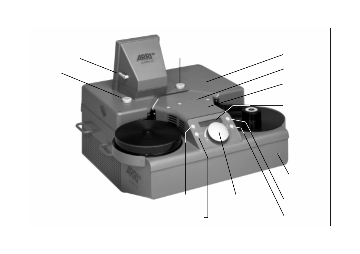
video setting knobadjusting lever
optics‘ cover
focus knob
“Mode“ key
“Lamp“ key
Master Control
Knob
sliding switch
lamp cover
display
IR-Receiver
“Reset“ key
“Film“ key
Page 3

1. Contents
1. Contents 3
2. Safety 5
3. General Product Information 7
4. Unpacking and Installation 9
5. Initial Operation 11
5.1 Precautions for Shipping .................... 11
5.2 Video-Option ....................................12
5.3 Format masks....................................13
5.4 IR-Remote Control .............................. 15
5.5 Switching on the LOCPRO 35 ............. 16
5.6 Switching on the HTI lamp .................. 17
5.7 Film loading ..................................... 18
5.8 Video...............................................19
6. Functions 21
6.1 Wall Projection ................................. 21
6.2 Highspeed Shuttle/Rewinding............. 25
6.3 Sprocket Projection ............................ 26
6.4 Loop Forming Position A/B ................. 27
6.5 Video...............................................29
6.6 ”Mode” Key (Unit Configuration) ........ 33
6.7 Controls ........................................... 36
6.8 Infrared Remote Control ..................... 41
6.9 Interfaces ......................................... 43
7. Service and Maintenance 45
7.1 Cleaning the Film Track...................... 45
7.2 Cleaning Mirror and Lens................... 47
7.3 Shipping and Storage ........................ 48
7.4 Replacing the Fuses ........................... 48
8. Technical Data 51
Serial Interface (X1) .................................... 53
Contents
3
Page 4

9. Trouble-Shooting Table 55
10. ARRI Service 68
11. Index 69
Contents
Annex Interfaces 79
Service Instructions 80
4
Page 5

2. Safety
The functions and workmanship quality of this unit were
tested at the factory. It complies strictly to the following
European Guidelines:
• Guideline 89/336 EEC of 3. May 1989
”Guideline of the Council of 3. May 1989 for bringing
into line the statutory regulations of the member
countries about electromagnetic side-effects.”
• Guideline 73/23 EEC of 19.02.73
”Guideline of the Council of 19. Feb. 1973 for
bringing into line the statutory
regulations of the member countries with respect to
electrical operating material for use within particular
voltage limitations.
The electric installation of the room in which the LOCPRO 35
is being used must comply with the demands of the IEC
commitments.
Warnings
For your own safety, please adhere to the following warnings:
Caution! – stands for danger of injury.
Attention!– equipment damage possible.
Note: Operational error possible!
General Safety Specifications
Caution: Danger of Injury!
Never reach into the film channel
while the LOCPRO 35 is running
or remove the covers!!
• In order to ensure safe and proper operation it is
essential that you acquaint yourself with this user
manual.
• Assembly and initial operation are to be carried out
only by persons familiar with the equipment.
Safety
5
Page 6

• Make sure the LOCPRO 35 stands securely and do not
block the air vents of the HTI lamp cooling fan on the
bottom side! See ➪ photo page 9.
• Keep all inflammable material away from the air vents
Safety
of the HTI lamp cooling fan.
see ➪ photo page 9.
• For sufficient air cooling, it is essential that the air
supply and escape vents on the sides are not blocked.
see ➪ photo page 9.
• Disconnect the unit from the mains before starting
maintenance or service!
Important Notes
• In humid weather please take the usual and customary
safety measures.
• In case of poor picture steadiness check the film guide for
possible contamination, such as e.g. splicing residues
or emulsion deposits.Clean if necessary! (see chapter 7.1)
• Optical surfaces should only be cleaned with an optic
cleaning brush. To remove sticky emulsion deposits, please
use an optic tissue, moistened with pure alcohol.
• Do not use solvents for cleaning!
• The unit is to be opened only by a qualified electrical
specialist. If fuses need to be replaced, ensure that
only the values indicated are used. See chapter 7.4.
• Repairs should be made by authorized service technicians only!
• Use only original replacement parts and accessories!
• Do not loosen the paint-secured screws!
Product Identification
Please always refer to the model type and unit serial number
when ordering spare parts or requesting information.
Explanation of the Symbols
• Follow the maintenance instructions in this user manual.
➪ photo refers to objects identified by pictures, photos
• Follow the shipping and storing instructions.
6
or graphs.
Page 7

3. General Product Information
The LOCPRO 35 is a lightweight mobile projector for onlocation use. A switch-over mirror system allows either wall
projection or the use of a 1/3” CCD Color High Resolution
video camera. The LOCPRO 35 can synchronize DAT-recorders or perfotape players for picture/sound synchronization.
The following sync signals are available for output: For
synchronization with DAT recorders a timecode LTC signal,
for synchronization with perfotape players in connection
with ASU-accessory (Audio Sync Unit) a biphase signal
with a programmable number of pulses per picture.
•
Fast film transport and simple operation:
The film is transported by a motor with a directly-driven
double-sided sprocket wheel. This patented intermittent
film drive system is acute to less than 0.01 seconds at
any projection speed. Constant film tension and safe
film transport are ensured by computer-controlled drive
motors for both film carriers. The ”auto-stop” feature
stops the film automatically 6 ft (2 m) before the end
of the film.
Automatic detection of the winding direction makes it
unnecessary to manually switch over from winding
direction A to B.
The open film channel facilitates film loading once the
film has been placed onto the winding plate. All steps
from the formation of loop sizes to standby operation
are carried out fully automatically. In addition, a film
can be removed at any time even in the middle of a
film roll.
•
Direct high speed rewinding:
High speed rewinding and quick location of certain film
scenes is easily possible with the gentle high speed
shuttle/rewinding system. By simply turning the Master
Control Knob this system allows you to switch directly to
high speed winding at 200 fps and back to the chosen
projection speed. The frame counter remains active so
that after switching back from high speed winding to
projection speed, the frame line is automatically
repositioned to the correct setting.
General Product Information
7
Page 8

•
Excellent image quality with flicker-free projection:
Best possible image brightness, excellent picture steadiness and image quality are the outstanding features of
the LOCPRO 35. The 400 W HTI lamp allows optimum
projection of more than 6 ft (2 m) image width and an
average color temperature of 5.400°K.
The built-in video camera (optional) can be connected
to a monitor, video recorder or video printer. Two video
outputs are available, FBAS (BNC) and Y/C. In addition,
it is possible to mask the video image electronically to
match the different film formats as required.
•
Telecine Mode (Pulldown Mode):
Flicker-free transfer onto video tape at 24, 25 or 30 fps
is possible depending on the integrated video system 50 Hz PAL or 60 Hz NTSC. In both cases, the integrated
video camera synchronizes frame transport.
•
Sound Synchronization:
To synchronize DAT-players an LTC signal (timecode)
output is available. In connection with an ASU, a
biphase signal (synchronized picture change signal with
forward/reverse recognition) allows for synchronization
of perfotape players. For the adaption to different
perfotape players it is possible to program on the ASU
General Product Information
the pulses per picture and the max. acceleration.
The LOCPRO 35 is available in the following versions:
• LOCPRO 35 St 230V/50Hz. ...... Id.No. M1.83000.0
• LOCPRO 35 St 115V/60Hz. ......Id.No. M1.83000.A
• LOCPRO 35 TV 230V/50Hz. ..... Id.No. M1.83000.B
with integrated CCD video camera (PAL)
• LOCPRO 35 TV 115V/60Hz. ..... Id.No. M1.83000.C
with integrated CCD video camera (NTSC)
8
Page 9
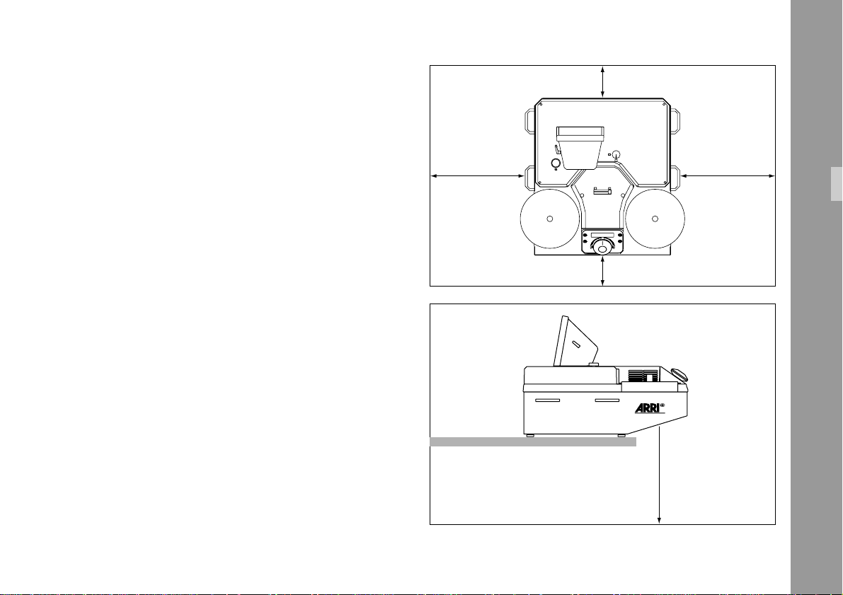
4. Unpacking and Installation
min. 100 mm min. 3.9"
In order to prevent condensation from forming on individual
components, the LOCPRO 35 should be kept in its packing
an additional day (before unpacking), if the temperatures
during shipping (cold) vary extremely from those temperatures in the installation area (warm).
1) Cut off the packing straps.
2) Lift off the packing in an upward direction.
3) Take out the additional items (User Manual, projection
lamp, accessories, maintenance kit).
4) Remove the plastic foil.
5) Always transport the projector to its destination in its
shipping or projection case and lock caster lock levers.
Note: Optimum wall projection of 2300 mm (6.6ft) is
reached when the LOCPRO 35 is installed in such
a way that there is a distance of 4 m (12 ft) between the back of the unit and the projection wall.
min. 100 mm
min. 3.9"
RESET
MODE
CLOSE
ON/OFF
ADJUST
OPEN
LAMP
FILM
min. 300 mm min. 11.8"
LOCPRO 35
min. 300 mm
min. 11.8"
min. 500 mm
min. 19.7"
Unpacking and Installation
9
Page 10

The LOCPRO 35 must stand on a solid flat
surface and should be disconnected from the
mains before it is moved.
Lift the LOCPRO 35 out off its shipping case and set it up
in such a way that the air vents on the bottom of the lamp
cooling fan ➪ photo are not obstructed. Observe the
clearances on the top and sides, see ➪ photo page 9.
Keep all flammable materials away from the
exit vents of the lamp fan.
Do not cover up the HTI ventilation ducts.
Unpacking and Installation
10
Page 11
5. Initial Operation
5.1 Precautions for
Shipping
In order to avoid shipping damage the safety
screw must always be screwed in each time the
unit is transported..
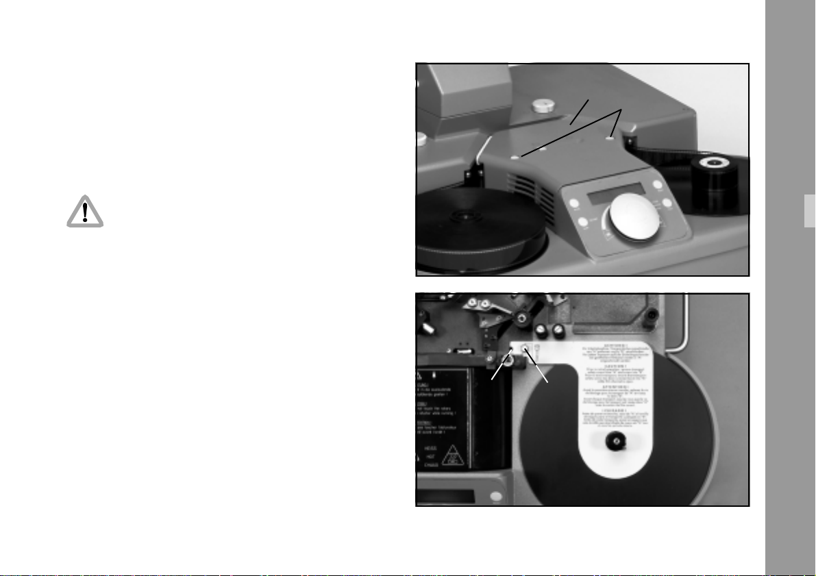
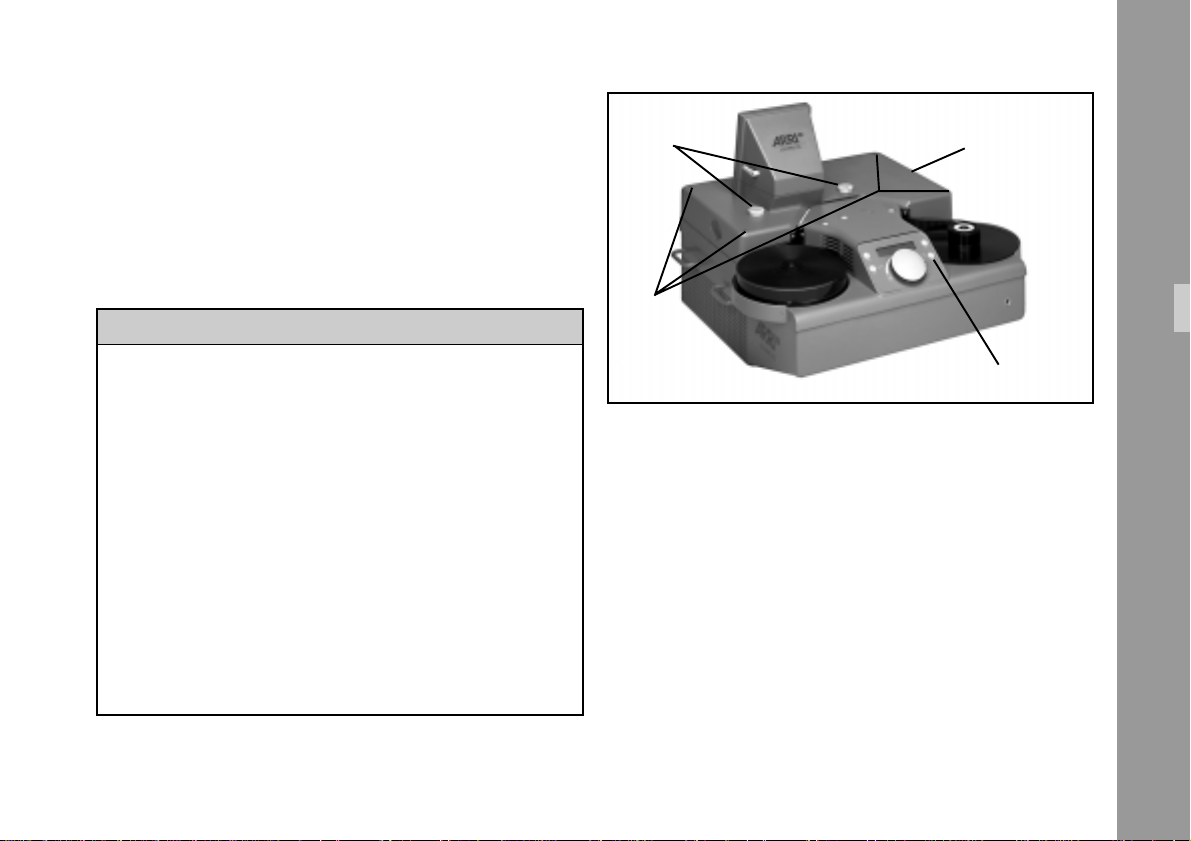
1) Depress spring-loaded latches on lamp cover
➪ photo and lift off lamp cover.
lamp cover
spring loaded latches
2) Remove the shipping safety screw ➪ photo.
To store the screw for subsequent use, screw it into the
bore-hole ➪ photo.
Initial Operation
bore hole safety screw
11
Page 12
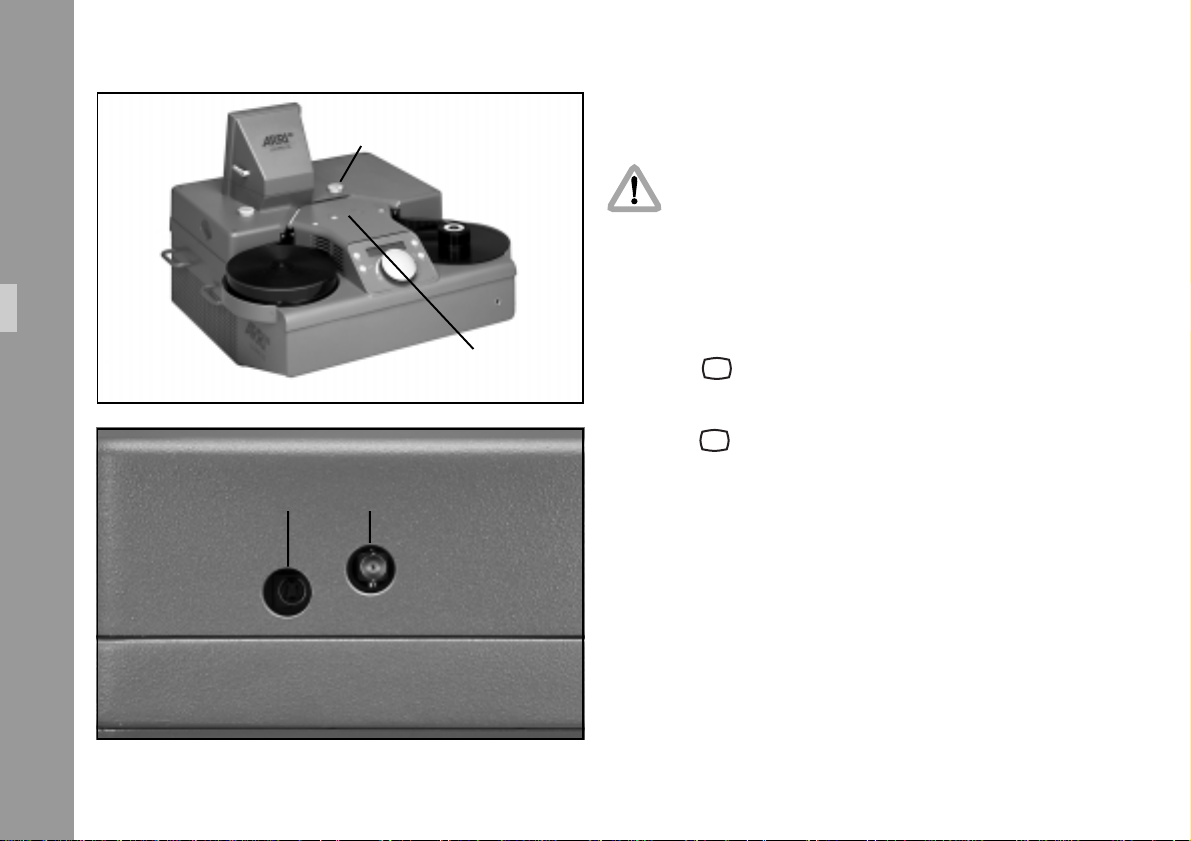
setting knob
5.2 Video-Option
The LOCPRO 35 must be switched off before
connecting it to an interface cable or DATrecorder or perfotape player.
1) Connect the monitor via BNC-or Y/C-cable to the
appropriate socket ➪ photo on the LOCPRO 35.
Initial Operation
Y/C-socket
12
BNC-socket
slide switch
2) Set mirror with selection knob ➪ photo to the TV
symbol.
3) Shift slide switch on lamp cover ➪ photo to the TV
symbol.
Note: Video ”on/off” is only possible when the
Master Control Knob is in the ”0” position, i.e.
when the film is not being transported.
4) Switch on TV monitor.
5) Adjust monitor for optimum image quality.
Page 13
5.3 Format masks
The standard aperture size of 18.6 x 24 mm can be
adapted to the various projection formats by using format
masks.
The following masks are available:
hoodcontrol knobs
Type ........................................................... Ident No.
Film Gate Mask Set (13 masks incl. case) . M2.81853.0
Mask 1:1.37 ACAD ............................... M2.81876.0
Mask 1:1.66 WIDE SCREEN ................... M2.81877.0
Mask 1:1.85 WIDE SCREEN ................... M2.81878.0
Mask 1:2.35 SUPER 35 .......................... M2.81885.0
Mask 1:1.85 SUPER 35 ......................... M2.81882.0
Mask 1:1.78 HDTV S35......................... M2.81881.0
Mask 1:1,78 HDTV ................................ M2.81879.0
Mask 1:1.66 SUPER 35 .......................... M2.81880.0
Mask 1:1.33 TV-ISO .............................. M2.81875.0
Mask 1:2.35 S 35 ABOVE ...................... M2.81886.0
Mask 1:1.85 S 35 5 VERS ...................... M2.81883.0
Mask 1:1.8 S 35 5.7 VERS. .................... M2.81884.0
Mask 1:1.78 SUPER 35 HDTV –3-PERF: ... M2.81908.0
4 screws
“Film“-key
5.3.1 Exchanging the film gate
format mask:
Insert format mask:
• Open the film channel with ”Film” – key
• Switch off the main power supply.
• Remove optics cover.
Remove the control knobs and the 4 screws with an
Allen key SW3. See Chapter 7.2 (# 2)
Initial Operation
13
Page 14
• Remove lens. See Chapter 7.2 (# 4)
Initial Operation
• Check that the film gate frame and the surface of the
film track are clean.
• Replace lens.
• Replace optics cover.
Remove format mask:
• Open film channel with ”Film” – key
• Switch off main power supply.
• Remove optics cover. See Chapter 7.2 (# 2)
• Remove lens. See Chapter 7.2 (# 4)
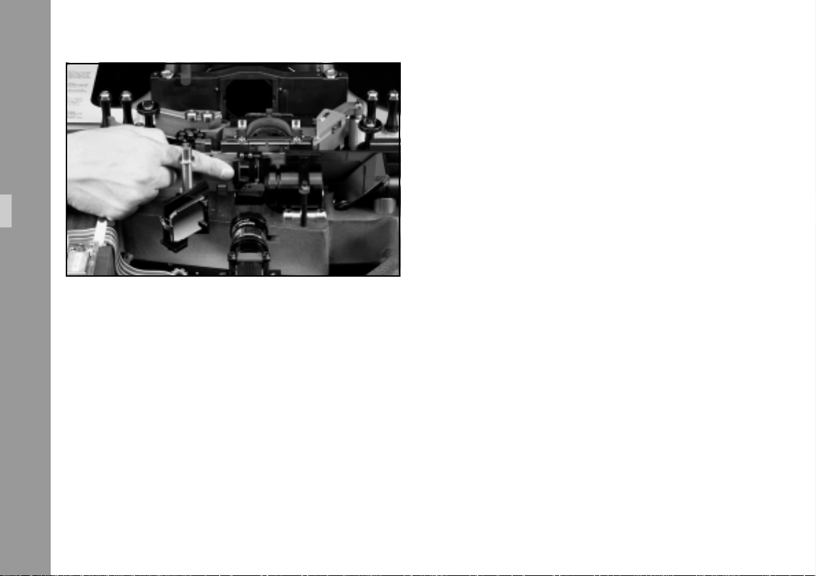
• Remove the mask from the film gate by gently pressing
back the mask and then sliding it back out to the right
➪ photo.
14
• Insert the format mask with the film gate frame facing
the film gate (frameless side facing upward) by sliding
the mask in from the right side into the spring-loaded
support of the film track until the mask engages with
the film gate.
• Check the film gate mask for correct positioning.
• Replace lens.
• Replace optics cover.
Page 15

5.4 IR-Remote Control
The IR-Remote Control (an accessory) consists of a handheld transmitter ➪ photo and a receiver ➪ photo
mounted on the front of the LOCPRO 35.
In order to guarantee trouble-free operation, there should
be no partition walls or other obstacles between transmitter
and receiver.
• Unpack the remote control and insert the batteries
making sure to observe the correct polarity.
IR-receiver
Initial Operation
15
Page 16
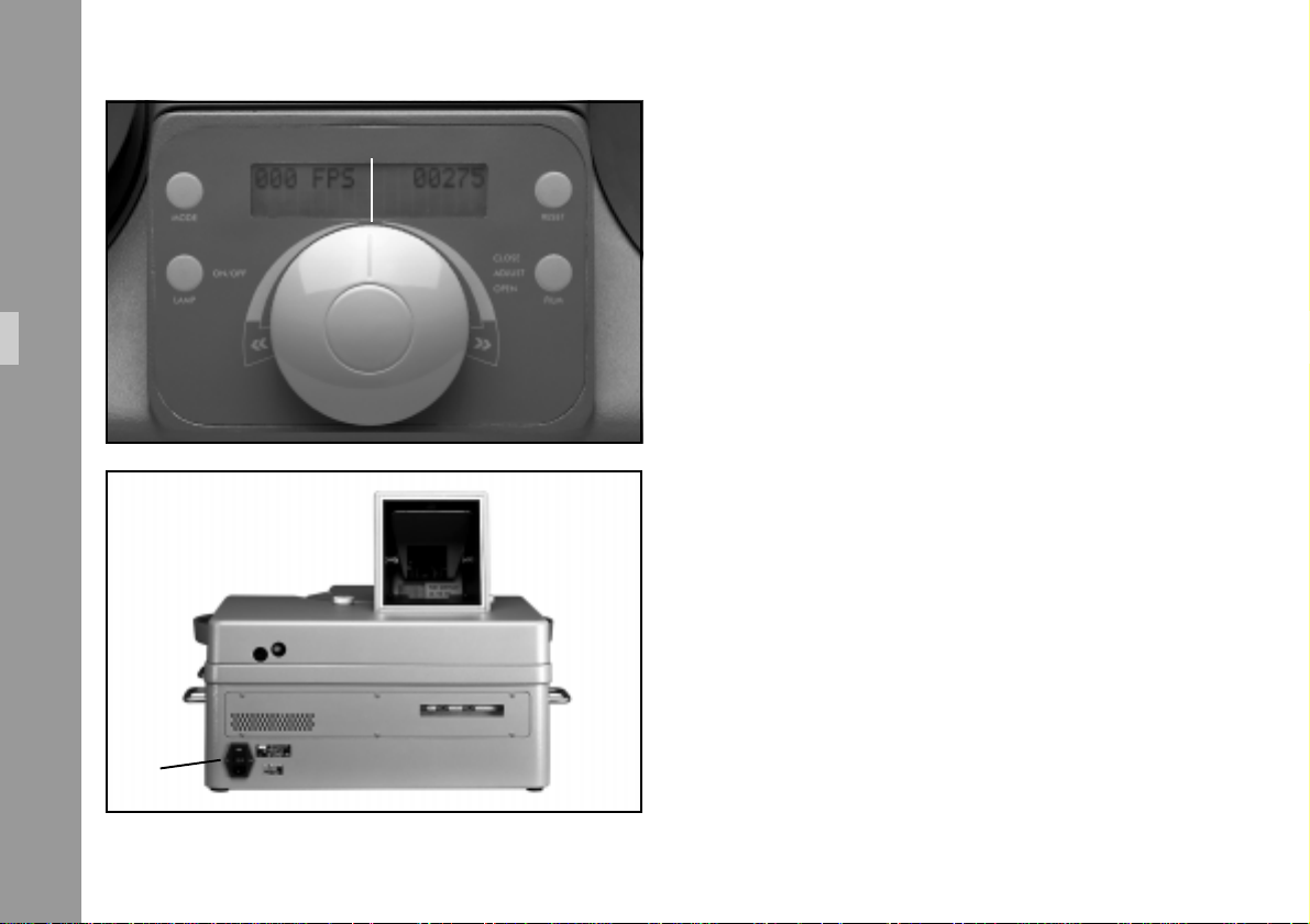
master control knob
Initial Operation
mains switch
5.5 Switching on the LOCPRO 35
1) Set the Master Control Knob ➪ photo to ”0” position.
2) Switch on the mains switch ➪ photo on the back of
the unit.
16
Page 17
5.6 Switching on the HTI lamp
Before switching on the HTI lamp, please ensure that
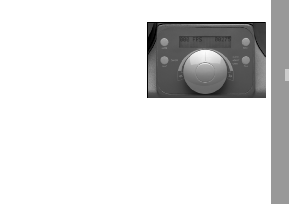
• The Master Control Knob ➪ photo is in the ”0” position.
• Film is not running in the projector.
1) Depress ”lamp” key for approx. 1 second to ignite the
lamp. During this ignition phase, which lasts approx.
5 seconds, all key functions are disabled.
master control knob
“lamp“-key
2) The HTI lamp can be switched off after a reset time of
5 seconds by depressing the ”lamp” key again.
Note: Run-up time to full light power is approx. 40
seconds. Working temperature of the lamp is
reached in three minutes. During this period the
lamp should never be switched off, because this
gradually reduces the life of the lamp and
results in poor ignition behavior.
Initial Operation
Note: The average life of an HTI lamp
is approx. 750 hours.
Spare lamps can be ordered under
Id.No. 05.09873.0.
17
Page 18
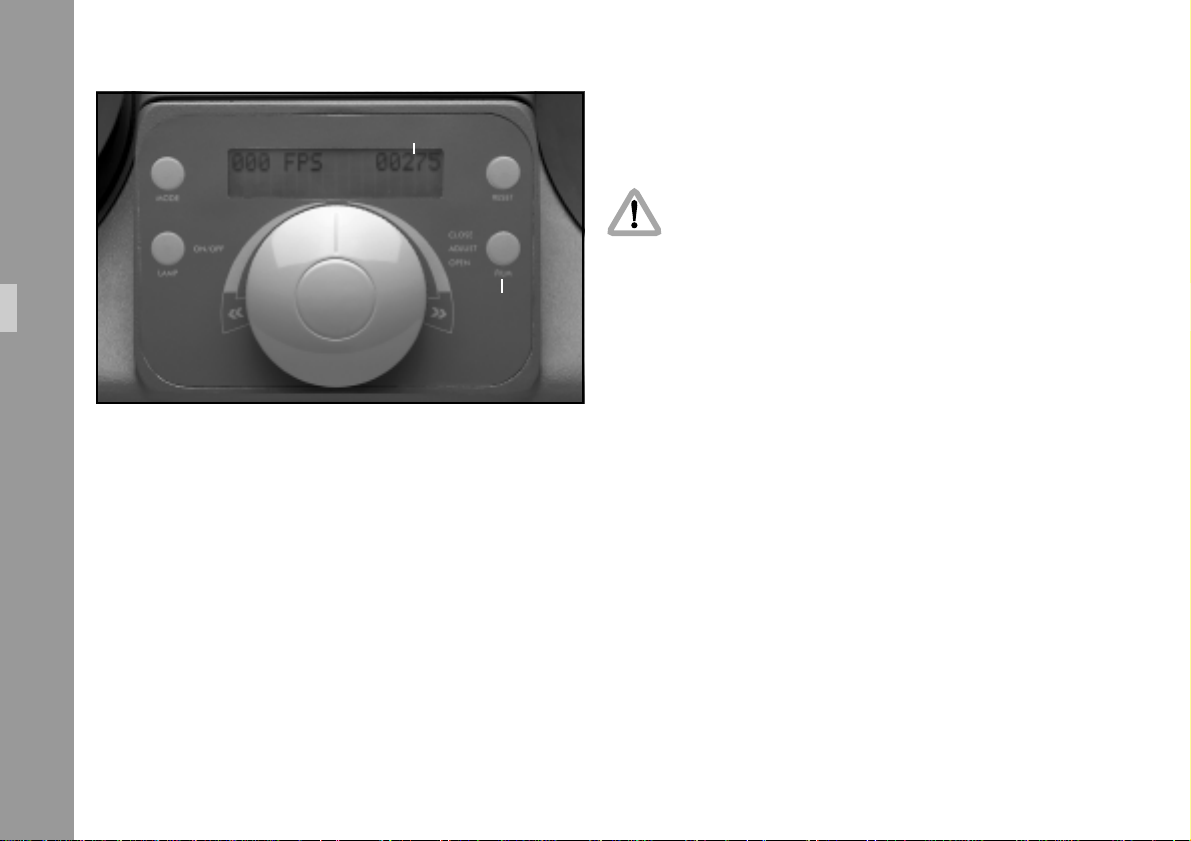
frame counter
3) Insert film into the film channel and fix end of the film
in the film core of the right winding plate. Then wind
up approx. three turns.
Ensure same winding direction on both plates!
To avoid damage of film track do not use
stapled film.
Initial Operation
5.7 Film loading
1) Place the film roll with the neg. film on the left film
plate so that the emulsion side is facing the operator.
If a print film is projected, the emulsion side must be
on the opposite side.
2) Open the film channel by depressing ”film” key ➪ photo
for some time (>1s).
18
“film“- key
4) Tighten both film rolls.
5) Press ”film” key briefly.
The feed carriage closes the film channel.
The film loop is formed automatically and the frame
counter ➪ photo is reset to ”0”.
Note: Inside or outside winding direction (A/B) are
recognized by the projector.
Page 19
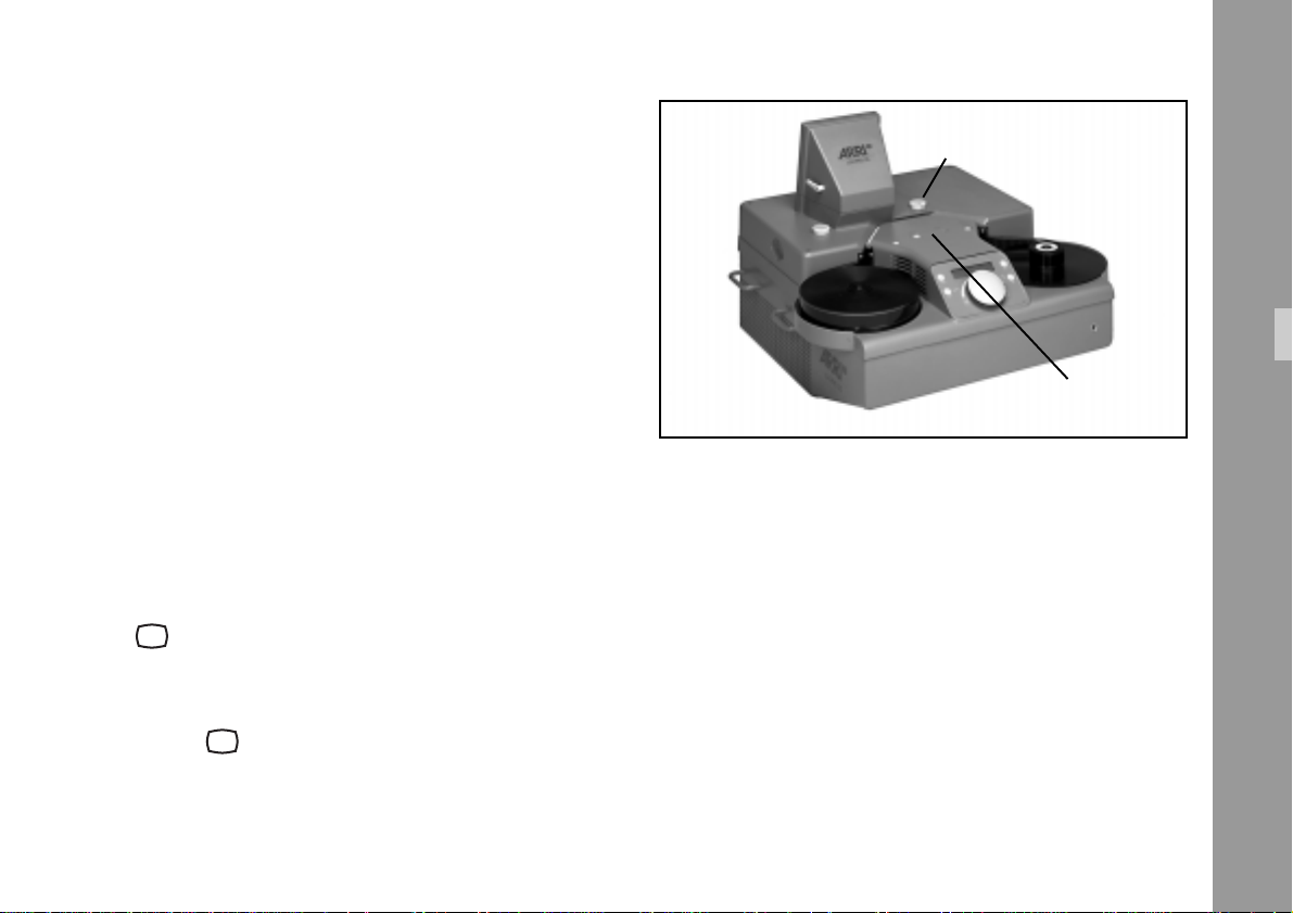
5.8 Video
As an option, the LOCPRO 35 can be equipped with a
video system.
5.8.1 Video camera
The LOCPRO 35 TV is available with two video camera
versions.
50 Hz unit:
50 Hz shutter (open sector 79°) with PAL video camera.
60 Hz unit:
60 Hz shutter (open sector 71°)with NTSC video camera.
Starting video camera operation
setting knob
slide switch
Initial Operation
1) Swing the mirror out of the optical path to the TV symbol
with selection knob ”video” ➪ photo.
2) Shift the slide switch ➪ photo to the right to the TV
symbol .
Note: Switch-over to video operation is only possible
during still projection and when film is not being
transported (sync phase of revolving shutter
from internal quartz to video synchronization).
19
Page 20
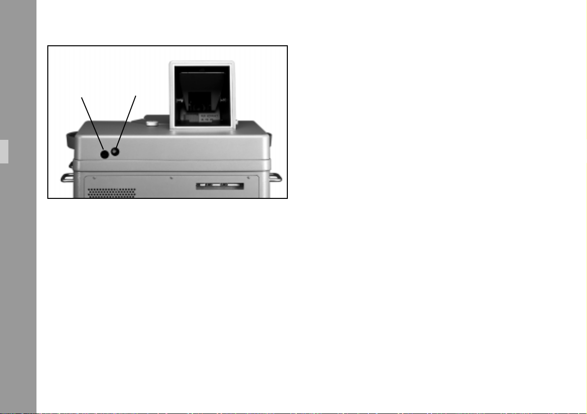
FBAS (BNC)S-VHS (Y/C)
Initial Operation
5.8.2 Video outputs TV
Video output sockets provide FBAS (BNC) ➪ photo and
S-VHS (Y/C) ➪ photo signals from the color CCD video
camera.
A monitor, video recorder, video printer can be connected
to the LOCPRO.In addition the video images can be
transferred to an image processing computer.
20
Page 21
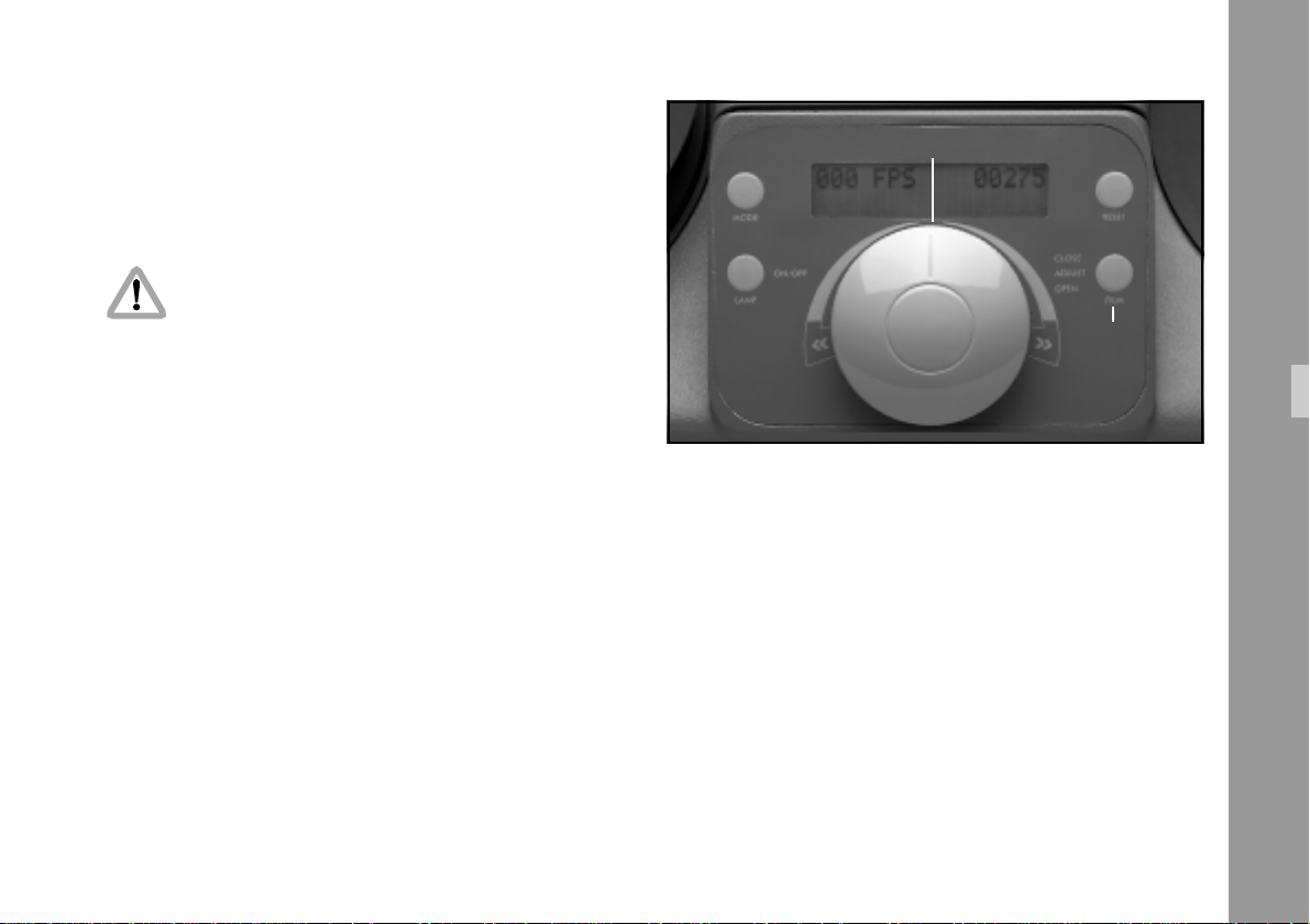
6. Functions
6.1 Wall Projection
The LOCPRO 35 must stand on a solid, flat
surface and should be completely disconnected
from the mains before it is moved.
See also notes in chapter 4.
Optimum wall projection of approx. 2.3 m (7 ft) width is
reached at a distance of 4 m (12 ft), measured from the
back of the unit to the projection wall.
6.1.1 Frame line
master control knob
“film“- key
Functions
After closing the film channel (see chapter 5.7), adjust the
frame line, if necessary.
Note: Frame line adjustment is only possible during
still projection.
1) Master control knob is in ”0” position (no film transport).
2) The frame line (horizontal line in the projected picture)
can be shifted out of the visible picture by briefly
depressing the ”film” key ➪ photo.
Each keystroke shifts the frame line by 1/4 frame.
21
Page 22
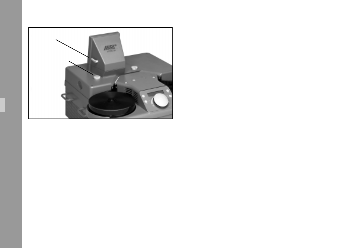
adjusting lever
focus knob
Functions
6.1.2 Image Position and Focus
• The projected image can be tilted upward up by 15°
with the projection height adjusting lever ➪ photo.
• Focus is adjusted with the rotary focus knob ➪ photo.
22
Page 23
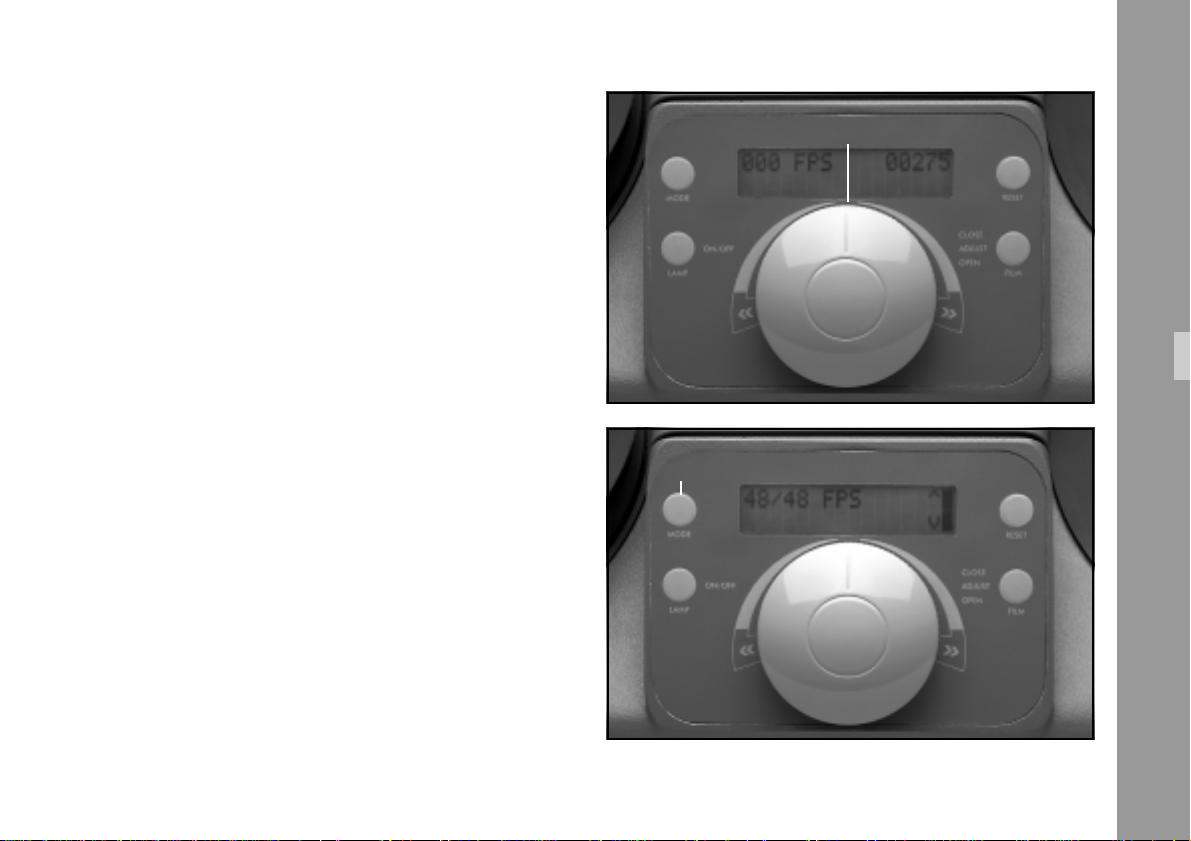
6.1.3 Frame Rate
The frame rate can only be set after the mains has been
switched on and the film channel is closed. Ensure that
the Master Control Knob ➪ photo is reset to ”0” each
time after the film channel has closed.
master control knob
1) Select the requested frame rate (visible on the display)
by turning the Master Control Knob ➪ photo. The
film now runs at the selected speed.
The following frame rates can be chosen for forward and
reverse operation:
• 50 Hz Version
1.56-3.12-6.25-12.5-25-50 fps (standard)
Highspeed shuttle 200 fps
48-24-30 fps can be selected directly via ”Mode” Key
➪ photo (see chapter 6.6).
• 60 Hz Version
1.87-3.75-7.5-15-30-60- fps (standard)
Highspeed shuttle 200 fps
48-24-25 fps can be selected directly via ”Mode” Key
➪ photo.
Functions
“Mode“- key
23
Page 24
Note: The reduced running speeds (1 per
thousand with switched on NTSC
video operation) are displayed as the
non-reduced speeds, e.g. 59.94 fps is
displayed as 60 fps.
Functions
2) In ”0” position (center position) the film transport is
stopped.
3) The ”autostop” stops the film run approx. 2 m (6 ft)
before the film end.
Attention: Film channel cannot be opened
during film run.
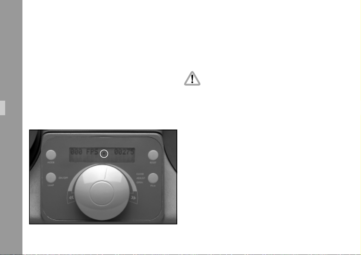
6.1.4 Single Frame Operation
If, during still projection, the Master Control Knob is turned
only slightly to the right or left of the ”0” position so that film
transport has not yet started, single frame release is possible. In
this case, a dot appears in the center of the display ➪ photo.
1) By briefly depressing the ”Film” Key, the film is
advanced by 1 frame.
2) If the Master Control Knob is turned to the left of the
”0” position, then single frame release to the left
becomes active. When turning to the Knob to the
right, single frame to the right is activated.
24
Note: Single frame operation is also possible via IR
remote control.
Page 25
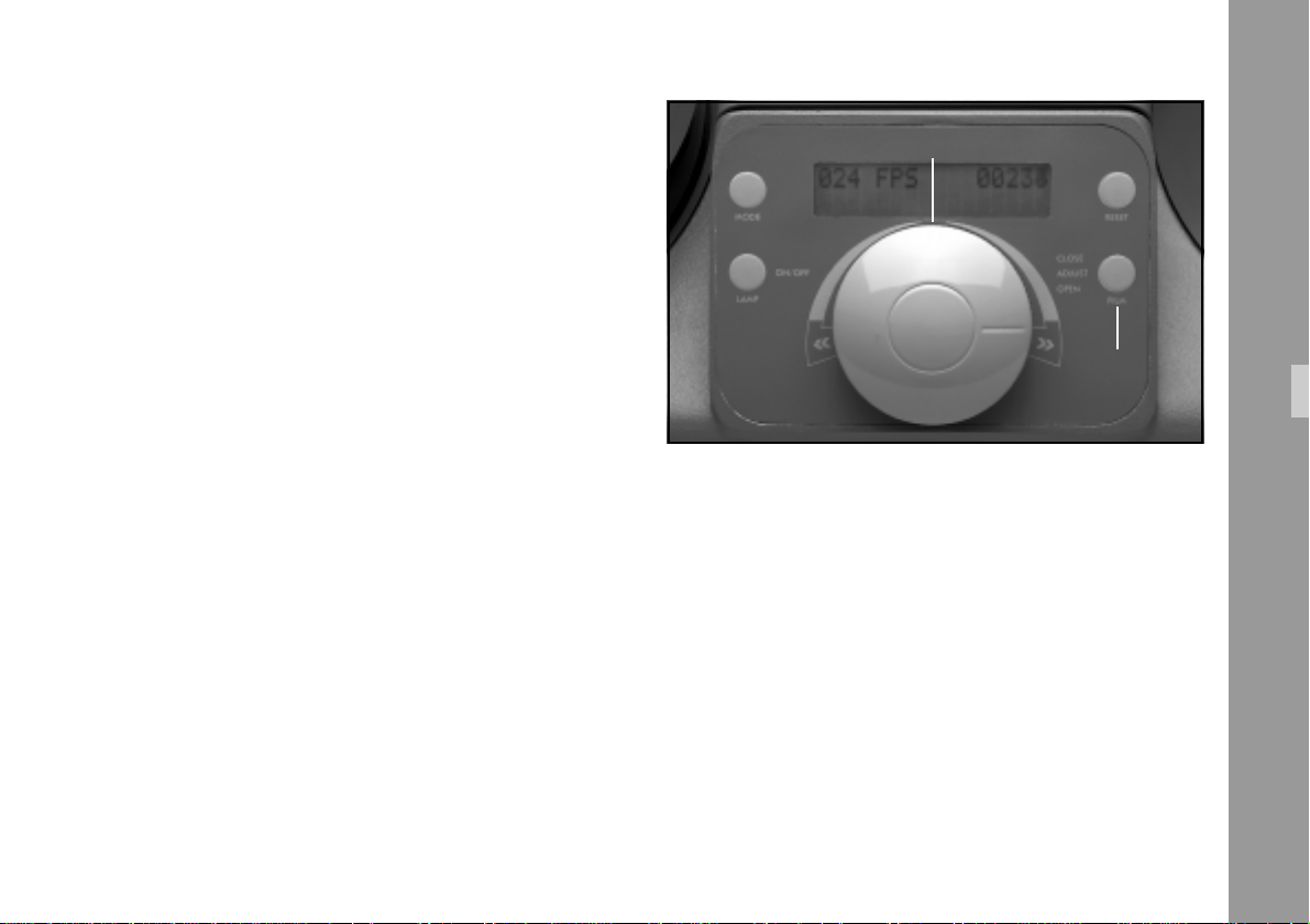
6.1.5 Autostop Function
In order to prevent the film from unintentionally running
out to the end, the auto-stop feature automatically stops
the film approx. 2 m (6 ft) before the end. This applies to
both film plates.
master control knob
Note: The auto-stop function is only ensured if the film
core used coincides with the value selected in
mode 4 (”more config” ”bobby size”).
Selectable diameters are 50 (2“), 75 (3“) and
100 mm (4“).
Disabling the Auto-stop Function
• To run the film completely through the film channel
without end stop, press the ”Film” Key ➪ photo
during projection or high speed shuttle. The frame
counter display flashes, the auto-stop feature is
disabled and the film runs through the film channel
without stopping.
The auto-stop function is reactivated by changing the
direction of film transport with the Master Control Knob.
Functions
“film“- key
6.2 Highspeed Shuttle/
Rewinding
By turning the Master Control Knob ➪ photo beyond the
highest projection speed to the left or right, the film runs at
a speed of approx. 200 fps in the selected direction.
During this high speed transport mode the film stage is
lifted up by magnets for safer film transport. When
releasing the Master Control Knob, film transport is
reduced to fastest projection speed.
25
Page 26
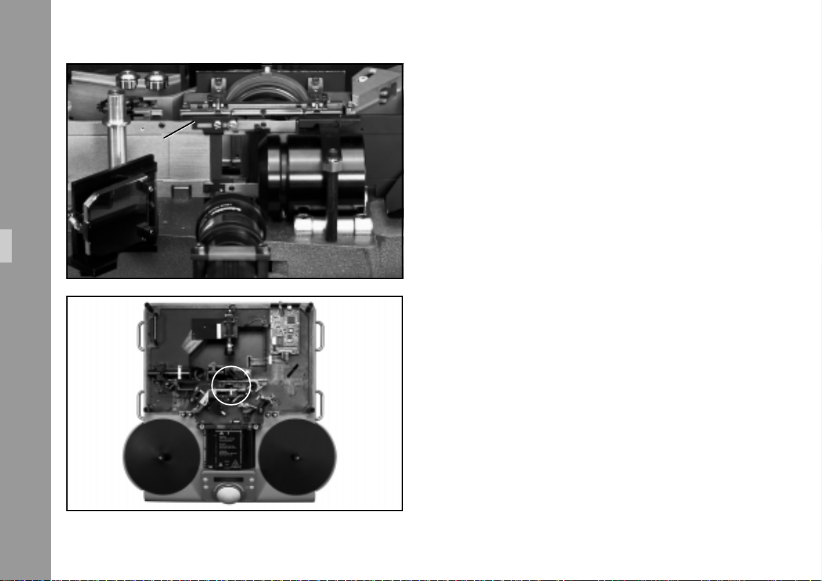
slide
Functions
6.3 Sprocket Projection
A slide on the film gate ➪ photo allows for a sprocket
projection.
For the evaluation of image steadiness and sprocket
quality, there are ports in the film gate ➪ photo, which
make it possible to check the sprockets both horizontally
and vertically.
26
Page 27
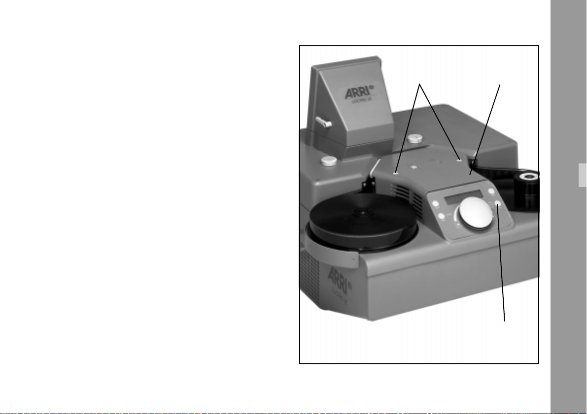
6.4 Loop Forming Position A/B
Positive and negative perforation films are projected in
optimum quality in the loop former – Position A.
snap locks lamp cover
Only in exceptional cases when special films have
negative perforations, it does become necessary to set the
loop former to position B in order to obtain an optimum
image quality.
• Open film channel with ”Film”-key.
• Switch off main power supply.
• Unlock lamp cover and remove.
Functions
“film“- key
27
Page 28
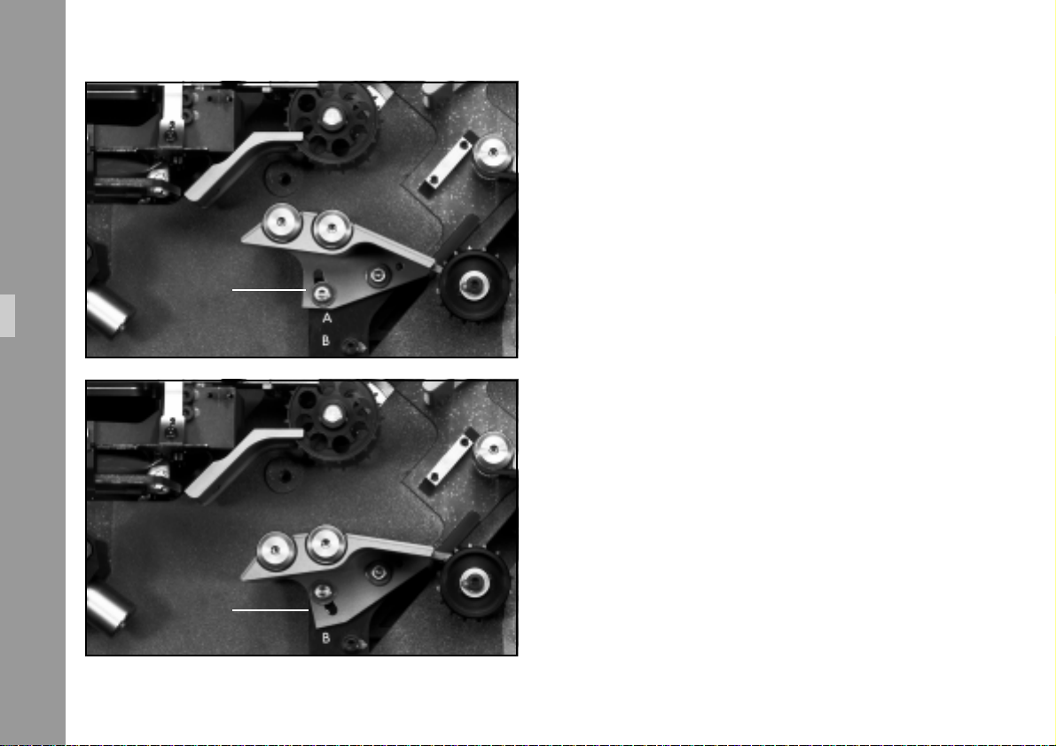
Functions
position “A“
position “B“
• Slightly loosen both fixing screws on the loop former
➪ photo and turn the loop former in the direction of
the user panel to position B.
• Tighten screws again.
• Replace lamp cover and secure.
28
Page 29
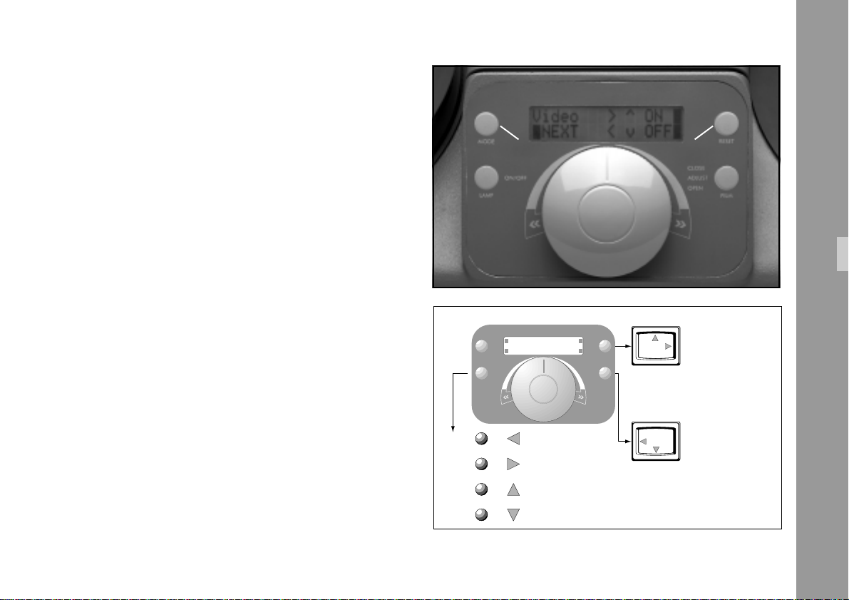
6.5 Video
Mode 2: Masking of Video Images
6.5.1 Masking of Video Images
It is only possible to mask a video image when the Master
Control Knob is in the ”0” position (still projection).
1) Connect a monitor to one of the two video sockets.
2) Select ”Video” (mode 2) by depressing the ”Mode”
Key ➪ photo.
3) Frame masking is activated with ”Reset” Key and
deactivated with ”Film” Key.
4) After the masking function is activated, select the side
to be masked (top, bottom, right, left) with ”Lamp” key.
Masking and shift direction arrows (<>^v) are only
visible on the monitor ➪ photo.
5) Adjust masking of the video image to the required
position by using the ”Reset” and ”Film” Keys.
“lamp“- key
1 X
2 X
3 X
4 X
MODE
ON/OFF
LAMP
“mode“- key
VIDEO
NEXT
selecting
the direction
for moving the mask
OFF
“reset“- key
“film“- key
Monitor
ON
RESET
CLOSE
ADJUST
OPEN
FILM
Monitor
direction
with "RESET"-key
direction
with "FILM"-key
Functions
29
Page 30

6.5.2 Video operation
The video camera can only be switched on and off when
the film is not being transported.
When the video camera in the LOCPRO 35 is switched on,
the revolving shutter and consequently, film transport are
automatically synchronized by the video signal of the
Functions
video camera.
In this case, the revolving shutter of the LOCPRO 35 runs
at 50 fps (PAL) or 59.94 fps (NTSC).
Cine Mode 48/48 is not suitable for video. The video
camera can be switched on, however, it is not in sync
with the LOCPRO 35.
The film transport speed depends on the position of the
Master Control Knob and the setting in the ”mode” menu
(see table).
PAL Video Camera
Menu Video filmtransport in fps (master control knob position)
Standard 50 25 12.5 6.25 3.12 1.56
48/48 off 482412 6 3 1.5
48/48 on not to be used (asynchronous)
50/50 off on 50 25 12.5 6.25 3.125 1.5625
24/50 off on 50 24 12.5 6.25 3.125 1.5625
30/50 off on 50 30 12.5 6.25 3.125 1.5625
30
Page 31
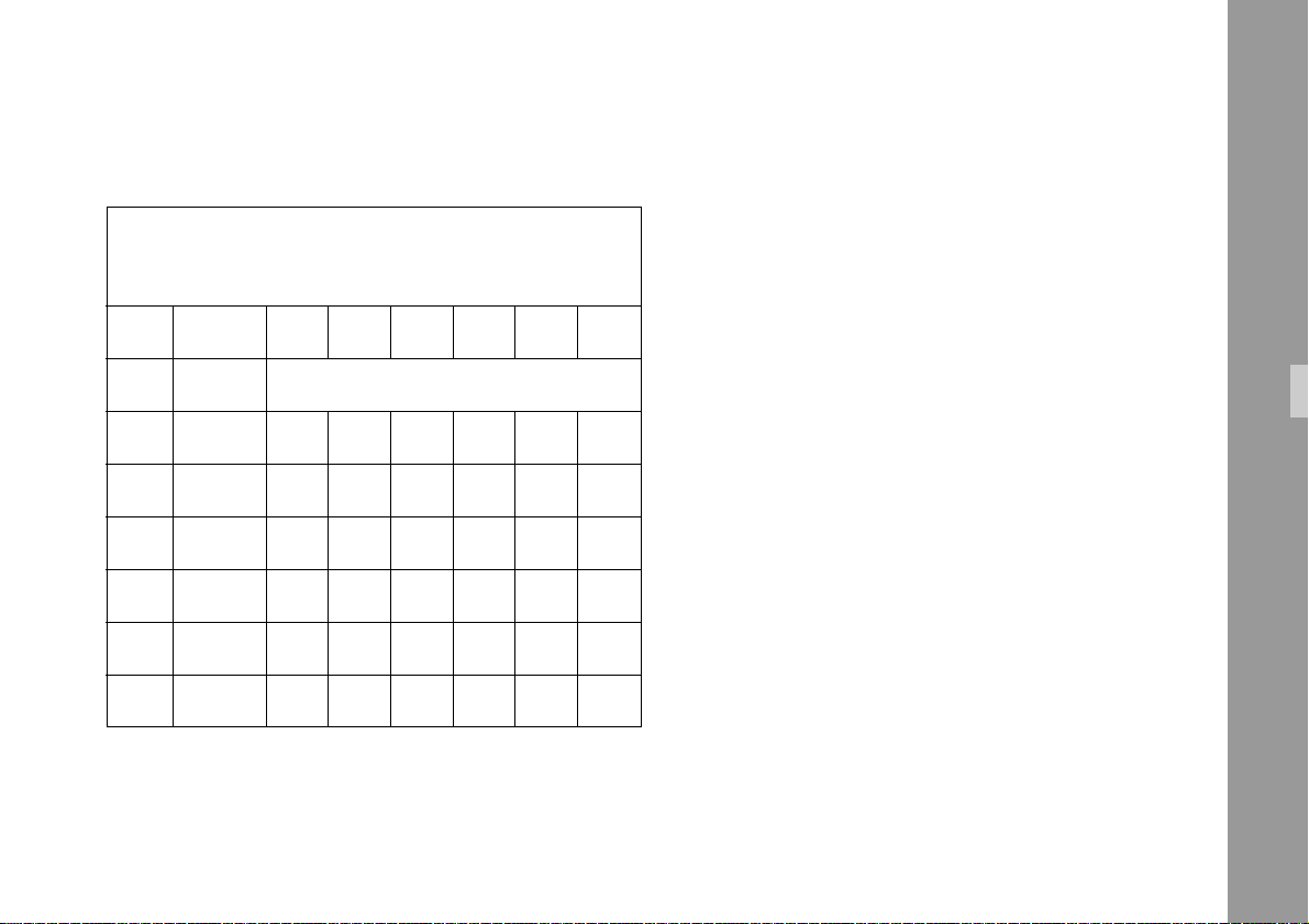
NTSC Video Camera
Menu Video filmtransport in fps (master control knob position)
Standard 60 30 15 7.5 3.75 1.875
Note: The digits after the decimal point are not shown
on the display.
The reduced transport speeds (1 per thousand
with NTSC Video Operation) are displayed as
the non-reduced speeds, e.g. 59,94 fps is
displayed as 60 fps.
48/48 off 48 24 12 6 3 1.5
48/48 on not to be used (asynchronous)
60/60 off 60 30 15 7.5 3.75 1.875
60/60 on 59.94 29.97 14.985 7.493 3.746 1.873
24/60 off 60 24 15 7.5 3.75 1.875
24/60 on 59.94 23.976 14.985 7.493 3.746 1.873
25/60 off 60 25 15 7.5 3.75 1.875
25/60 on 59.94 24.975 14.985 7.493 3.746 1.873
Functions
31
Page 32

6.5.3 Operation Modes
Cine Mode
Projection speeds of films shot at standard rates of 24 fps
and 25 fps can be selected via the ”Mode” Key.
Functions
Telecine Mode / Pulldown Mode
For the transfer onto video tape the corresponding
projection speed of 24, 25 or 30 fps (for 50 and 60 Hz
video) can be selected via the ”Mode” key.
Telecine Mode
If the LOCPRO 35 is equipped with a 50 Hz video camera
(PAL) the 24 fps or 30 fps film projection speed is automatically synchronized to the scan rate of the video camera.
Pull-down Mode
The pull-down mode is a special process for flicker-free
transfer of film with shooting frequency of 24 fps onto
video tape when an NTSC camera is used as film scanner.
32
Page 33
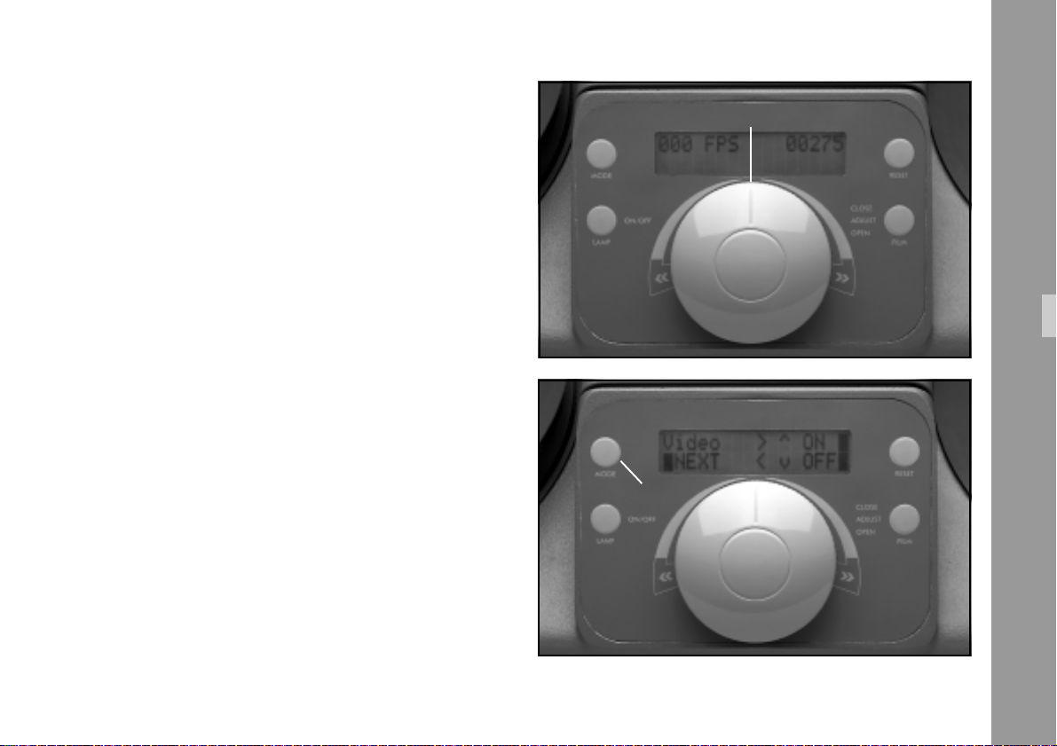
6.6 ”Mode” Key (Unit Configuration)
The frame rates are directly selectable and fixable via the
”Mode” Key.
master control knob
The ”Mode” Key only functions when the Master Control
Knob is in the ”0” position and the film is not being
transported.
Note: Those keys in the ”Mode” menu which can be acti-
vated are marked in the display with a dark bar.
Mode 1: Normal display view (with mains switch on).
Display left: Frame rate fps
Display right: Frame counter
(in case of error: error code)
Mode 2: Setup for video frame masking
Press ”Mode” key once
Display left: Video, Next
Display right: On/OFF
(see also chapter 6.5.1)
Functions
Mode 2: Masking of Video Images
“Mode“- key
33
Page 34
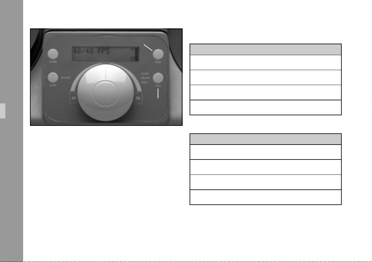
„Reset“- key
Frame Rate Selection 50 Hz projector:
Display fps fps max. Shutter Mode of operation
48/48 24 48 48 rps Cine Mode
50/50 25 50 50 rps Cine Mode
Functions
Mode 3: Setup speed
• Select desired speed by repeatedly pressing ”Reset”
key (higher value) or ”Film” key (lower value).
34
24/50 24 50 50 rps Telecine Mode
„Film“- key
30/50 30 50 50 rps Telecine Mode
Frame Rate Selection 60 Hz projector:
Display fps fps max. Shutter Mode of operation
Press ”Mode” Key twice
48/48 24 48 48 rps Cine Mode
60/60 30 60 60 rps Cine Mode
24/60 24 60 60 rps Pull down Mode
30/60 30 60 60 rps Telecine Mode
Page 35
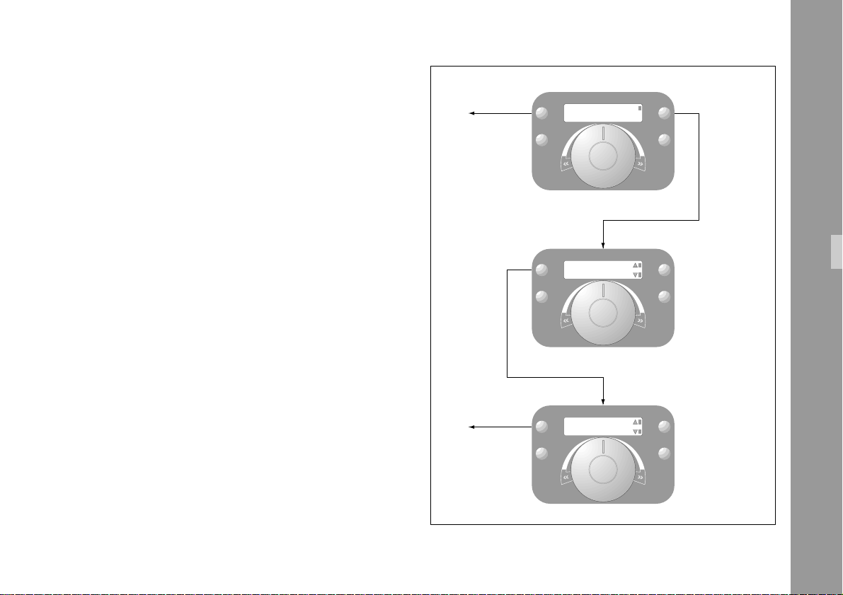
Mode 4: Select film type and film core diameter (Bobby
size) – Press ”Mode” key three times
Display left: More config.
Display right: Y
• Press ”Reset” Key 1 x
Display left: Perfo Corr.
Display right: Memory 1-5
Select requested memory (film type) by repeatedly
pressing ”Reset” Key (higher value) or ”Film” Key
(lower value).
Factory-programmed film types:
Color film pos. perforation (acetate) ........... memory 1
Color film neg. perforation (acetate) ........... memory 2
Color film pos. perforation (polyester)......... memory 3
b/w neg. perforation (polyester) ................ memory 4
• Press ”Mode” Key
Display film core (bobby size) e.g. 50 mm (2“)
Select requested film core diam. by repeatedly pressing
”Reset” Key (larger diam.) or ”Film” Key (smaller diam.)
Selectable diameters are: 50 (2“), 75 (3“) and 100mm
(4“).
End Setup
End Setup
MODE
LAMP
MODE
LAMP
MODE
LAMP
ON/OFF
ON/OFF
ON/OFF
MORE CONFIG Y
PERFO CORR 1
BOBBY SIZE
50 MM
ADJUST
ADJUST
ADJUST
CLOSE
OPEN
CLOSE
OPEN
CLOSE
OPEN
RESET
FILM
RESET
FILM
RESET
FILM
Functions
higher value
lower value
higher value
lower value
• Exit menu by repeatedly pressing ”Mode” Key (Display
in normal view)
35
Page 36
Functions
6.7 Controls
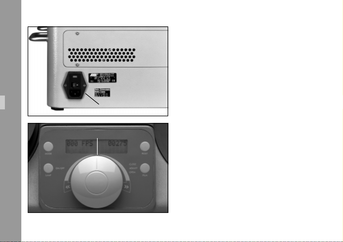
6.7.1 Mains switch
The mains switch is located on the rear panel of the projector
➪ photo.
36
mains switch
master control knob
6.7.2 Master Control Knob
The Master Control Knob ➪ photo is used to select the
frame rate, forward (turning to the right) and reverse
(turning to the left). For high speed winding/shuttle, turn
the Master Control Knob to either side, all the way to the
end stop.
Page 37
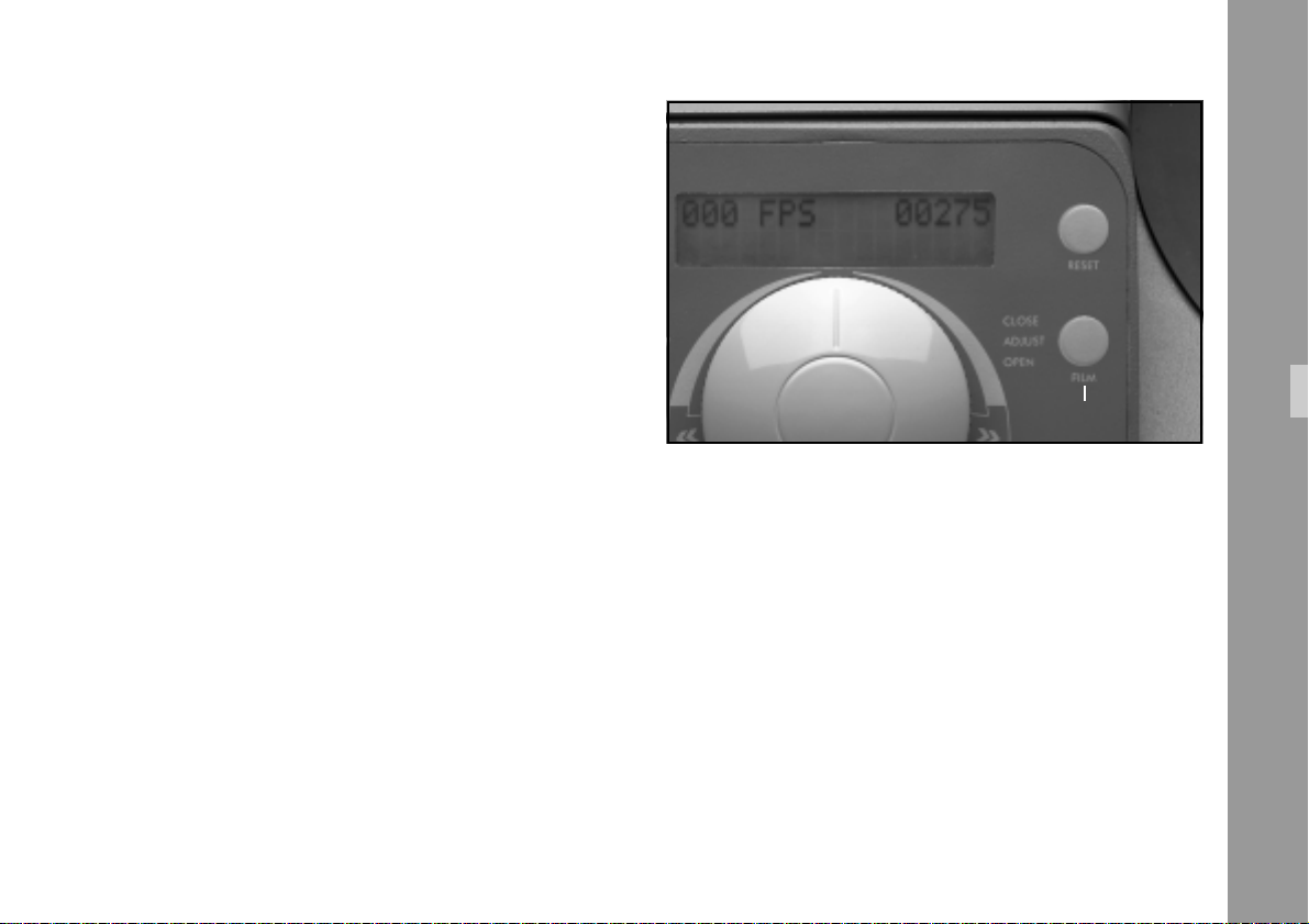
6.7.3 ”Film” Key
The ”Film” Key ➪ photo has six different functions:
•
Close the film channel:
When the film channel is in the open position, it can
be closed by pressing this key.
•
Open the film channel:
When the film channel is in the closed position, and
this key is depressed for more than 0.8 seconds, the
film channel opens.
•
Frame line adjustment:
When the film channel is closed and the Master
Control Knob is in the ”0” position (no film transport),
the frame line is shifted by 1/4 of the image with each
brief keystroke.
•
Single frame left:
When film channel is closed and Master Control Knob
is slightly turned to the left, off the ”0” position, a dotmark appears on the display (see chapter 6.1.4). Each
keystroke advances the film one frame to the left.
“film“- key
•
Single frame right:
When the film channel is closed and the Master Control
Knob slightly turned to the right from the ”0” position, a
dot appears on the display (see chapter 6.1.4). Each
keystroke advances the film one frame to the right.
•
Disabling the automatic end stop:
During normal film transport or high speed operation
(200 fps), the automatic end stop can be disabled. The
display flashes as long as this function is active.
Functions
37
Page 38
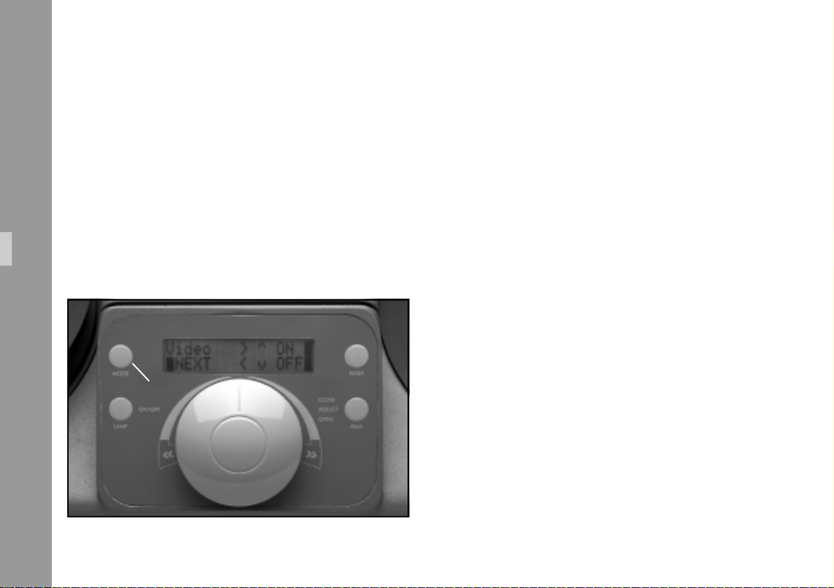
6.7.4 ”Mode” key
The ”Mode” key ➪ photo only functions, when the Master
Control Knob is in the ”0” position. Each stroke of this key
leads to the next lower menu level, i.e. from mode 1 to
mode 2, etc. (see chapter 6.6).
Functions
“Mode“- key
Mode 1: Normal viewing
The display shows the frame rate in fps on the
left sideand the frame counter on the right (if an
error occurs, an ”error” message will appear).
Mode 2: Video masking
Depress ”Mode” key once.
A video mask can then be positioned on all four
sides, and the masking function can be switched
on and off. The masks are only visible on the
video monitor. (see chapter 6.5.1 ”Masking of
Video Images”).
Mode 3: Frame rate selection
Press ”Mode” key twice.
The programmed frame rate can be changed
by repeatedly pressing of the ”Reset” key
(higher values) or of the ”Film” key (lower values).
Mode 4: Unit configuration
Press ”Mode” key three times.
In this mode the film type and film core diameter
can be selected (see chapter 6.6).
38
Page 39
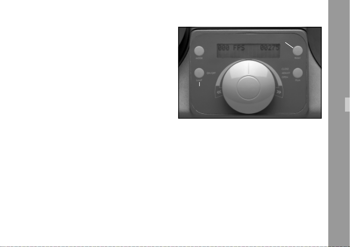
6.7.5 ”Lamp” Key
• The HTI-Lamp is ignited by pressing the ”Lamp” key
➪ photo.
• The HTI lamp is switched off by pressing the ”Lamp”
key again (5 seconds waiting time after switch-on).
“reset“- key
6.7.6 ”Reset” Key
• The ”Reset” Key ➪ photo resets the frame counter to ”0”.
• The ”Reset” Key is also used for settings described in
section 6.6.
“lamp“- key
Functions
39
Page 40
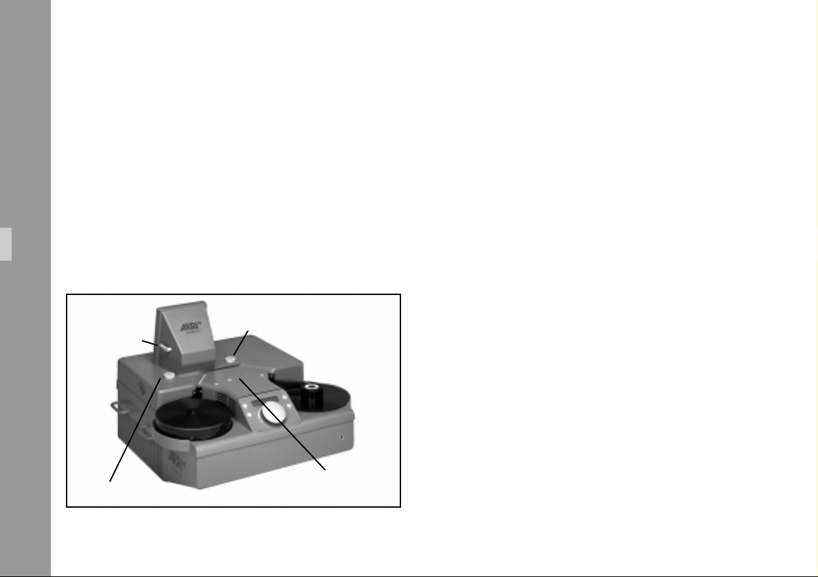
6.7.7 Control Knob ”Focus”
6.7.9 ”Video” Slide Switch ”VSS”
The control knob ”Focus” ➪ photo is used to adjust the
sharpness of the projected image.
6.7.8 Adjusting Knob ”Video”
Functions
With the “Video“ adjusting knob ➪ photo it is possible
to swing the mirror for video deflection in or out of the
optical path of the projector.
Adjusting knob “Video“
“Image Position“
lever
“Video“slide
“Focus“ control knob
switch
To switch on the video camera, shift the ”video” slide switch
➪ photo to the TV symbol. The Shutter/Video camera
synchronization is now controlled by the video camera, if
the unit is set to the normal ”Mode” (shutter 50 or 60 Hz).
Note: The speed in the menu ”Mode” should not be
set at 48/48 (Cine Mode).
6.7.10”Image Position” lever
The image position lever ➪ photo is used to shift the
projected image upward or downward on the projection
wall.
40
Page 41
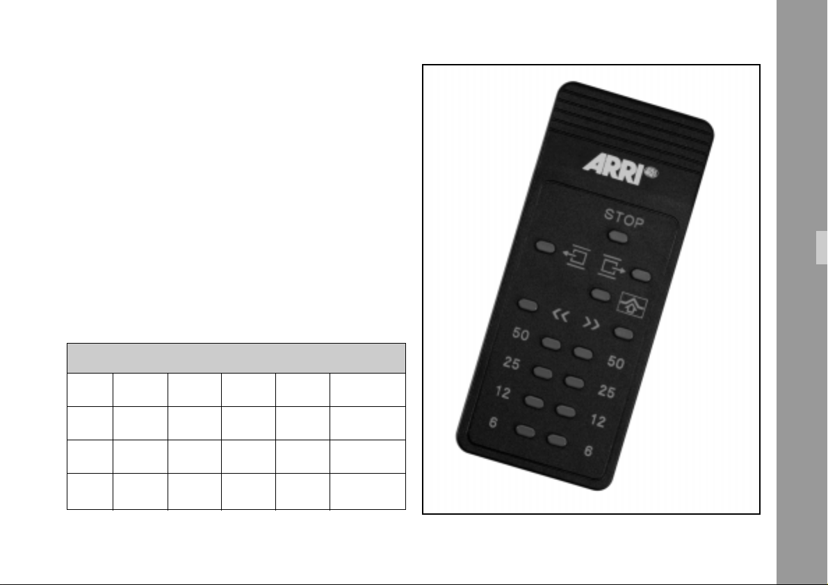
6.8 Infrared Remote Control
The following functions can be selected via remote control:
• Start: To start, press the key for the required frame rate
Note: This applies only to the standard settings 50/50
and 60/60. If these settings were changed in the
”Mode” function (Telecine Mode or Pulldown
Mode), then this frame rate prevails and is
selected. See chapter 6.5.2.
50 Hz-Version:
Menu key: 6 fps 12 fps 25 fps 50 fps Mode
48/48 6 12 24 48 Cine Mode
50/50 6 12 25 50 Cine Mode
24/50 6 12 24 50 Telecine Mode
30/50 6 12 30 50 Telecine Mode
Functions
41
Page 42
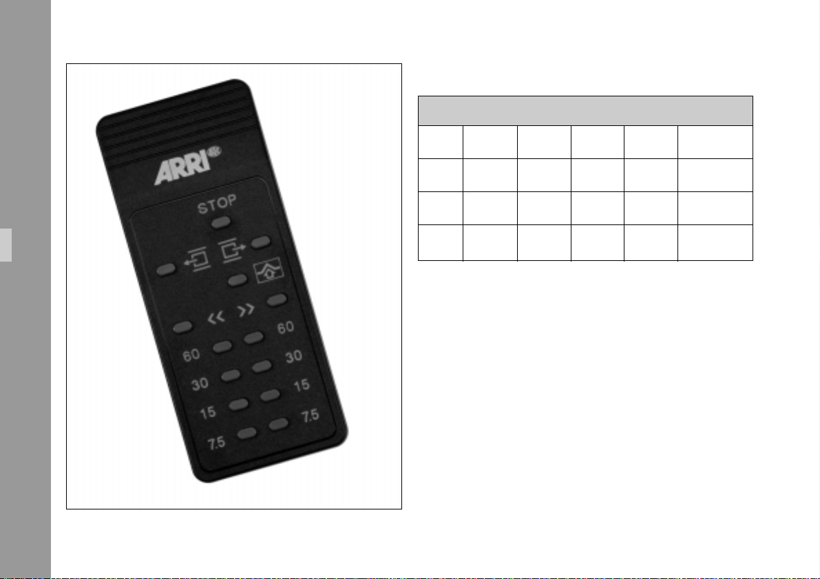
60 Hz-Version:
Menu key: 6 fps 12 fps 25 fps 50 fps Mode
48/48 6 12 24 48 Cine Mode
60/60 7.5 15 30 60 Cine Mode
Functions
42
24/60 7.5 15 24 60 Pulldown Mode
25/60 7.5 15 25 60 Telecine Mode
• Stop/Still Projection:
Press key with the current frame rate.
or press the ”Stop” key.
• High speed winding, forwards or backwards « ».
• Frame line shifting.
• Single frame, forwards or backwards.
If one of the single frame keys is held down,
the projection speed changes to: 3.12 fps at 50 Hz or
3.75 fps at 60 Hz.
Note: In case IR remote control fails, check batteries first.
Page 43
6.9 Interfaces
Note: All interface cables used must comply with CE
and EMV guide lines.
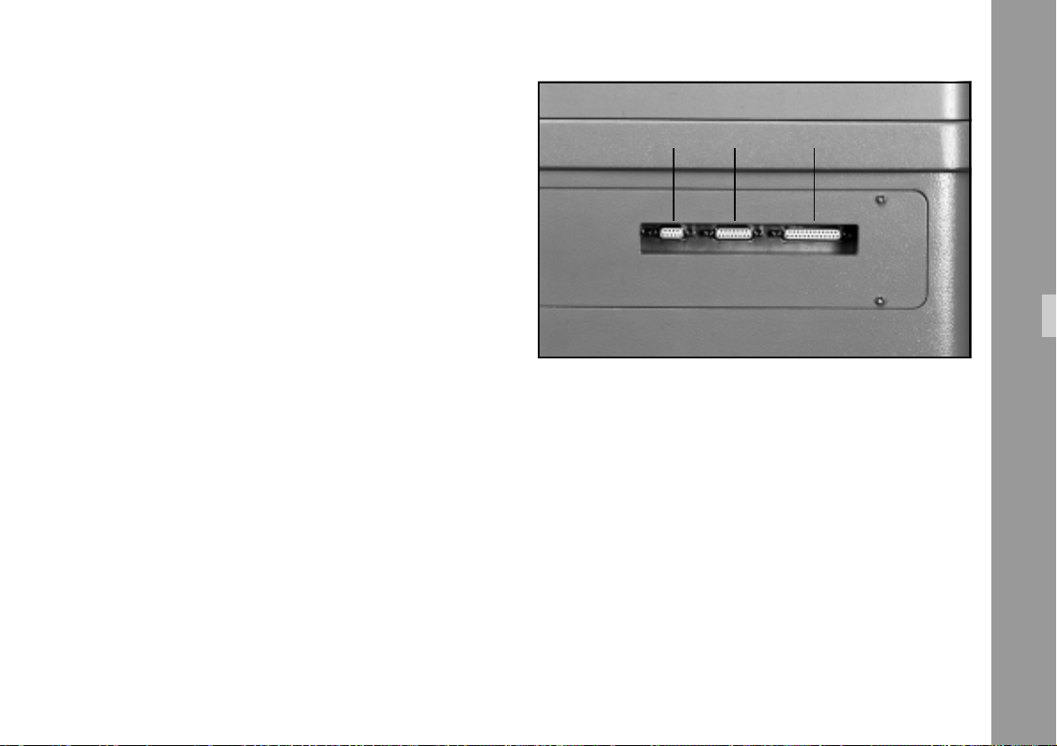
X1X2X3
6.9.1 Serial Interface (X1)
Plug type: Sub-D 25 pin socket
Via serial interface (X1) ➪ photo the operational status of the
LOCPRO 35 can be checked and changed from a computer.
Chapter 8 ”Serial Interfaces X1” contains listings of
technical data as well as listings of computer commands.
Plug – Pin configuration: See Annex ”Interfaces”
6.9.2 Ext Synchro (X2)
Plug type: Sub-D 15 pin socket
Via this interface ➪ photo a signal for shutter synchroni-
zation can be supplied externally and the internal shutter
signal accessed.
Functions
Cine Mode: ........................................................ 48 Hz
Normal and Telecine Mode: ....................... 50 or 60 Hz
Shutter revolutions can be changed by ± 3%.
Input: .................... 5 V TTL potential-free on optocoupler
Output: ................. 4 V potential output or potential-free
Plug Pin configuration: see annex ”Interface”
Note for shutter synchronization:
Signal source:
External = control frequency via X2; top priority!
Video = when video ”on”. Quartz of video camera.
Internal = internal quartz generator.
43
Page 44

6.9.3 Timecode (LTC) and Biphase A/B
(X3)
Timecode:
For sound synchronization of a DAT tape player with the
LOCPRO 35, e.g. during transfer of film and sound onto
video tape, a timecode signal is supplied on interface X3
Functions
➪ photo (see page 39).
The timecode signal (80 Bit per picture) is only supplied in
the forward running mode (to the right) with frame rates
of 24 fps, 25 fps or 30 fps. The read-out timecode frame
numbers correspond to those of the frame counter on the
display. A frame counter reset on the LOCPRO 35 therefore
also resets the timecode to zero.
The projection frame rate of the LOCPRO 35 has to be
matched to the DAT speed. This is possible via ”Mode”
Key (see chapter 6.4.2).
If the LOCPRO 35 is synchronized externally, ensure
accurate synchronization frequency within ± 1%.
1) Run the LOCPRO 35 and DAT tape player separately
to the sync point (starting position of transfer with
appropriate leader).
2) Connect the DAT tape player via interface cable (9 pin
Sub-D on XLP plug) with socket X3.
3) Reset frame counter to zero (”Reset” Key).
If necessary, set the timecode value supplied at the
sync point of the DAT recorder to offset so that the the
time code value ”0” emanating from the LOCPRO 35
corresponds to the value expected at the DAT recorder.
Start the transfer with the Master Control Knob.
Biphase:
Biphase operation is only possible with the Audio Sync
Unit (ASU).
To synchronize with external units, a sync pulse (1 pulse per
picture) is supplied on interface plug X3. When connected
to a programmable ASU, a biphase signal is generated
from this sync pulse.
(biphase A/B = moving direction recognition).
Plug type: 9-pin Sub-D socket.
44
Page 45
7. Service and Maintenance
To preserve optimum projection and image quality, it is
essential to check the brightness and image quality every
six months and, if necessary, during such a maintenance
service the LOCPRO 35 should be adjusted to meet
factory quality standards.(see ”Service Manual”).
Make sure that the LOCPRO 35 is switched off
and completely disconnected from the mains
before starting service or maintenance work.
Unplug all interface connections.
7.1 Cleaning the Film Track
Never use hard or metallic objects for cleaning.
We recommend using the ARRI Plastic Film
Track cleaning Skewer, Id.No. K5.26167.0 or
maintenance tool kit incl. Cleaning kit, Id.No.
M2.81126.0. Both items can be ordered.
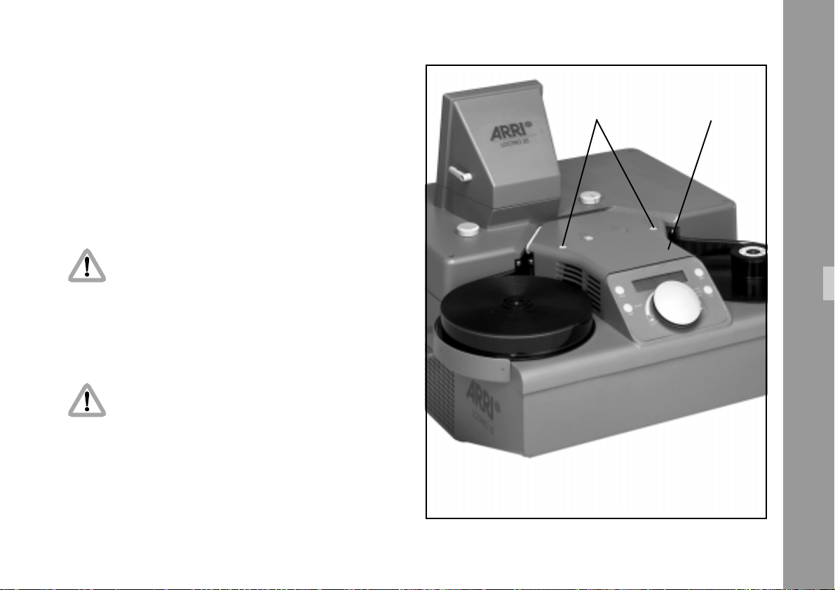
1) Press the snap locks ➪ photo on the lamp cover and
remove lamp cover.
snap locks lamp cover
Service and Maintenance
45
Page 46
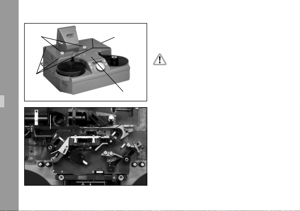
4 screws
optic covercontrol knobs
lamp cover
2) Pull off the control knobs ➪ photo upward.
3) Remove all four screws ➪ photo with hex. Wrench
SW3 and lift off optics’ cover completely.
Attention:
Do not damage BNC and S-VHS plug and
make sure that there is no cable connected to
the BNC or S-VHS plug!
4) Remove emulsion deposits and possible adhesive
residues from film track ➪ photo, deflection runner 1
and 2 ➪ photo and loop box left.
loop box
deflection
runner 1
Service and Maintenance
46
filmtrack
deflection
runner 2
5) Replace lamp cover.
6) Replace optic cover
7) Replace control knobs and fasten optic cover with the
screws.
Page 47
7.2 Cleaning Mirror and Lens
Note: Mirror surfaces should only be cleaned if
necessary, as too frequent cleaning reduces the
life of the mirrors (surface silvering). Slight dust
does not visibly affect image quality.
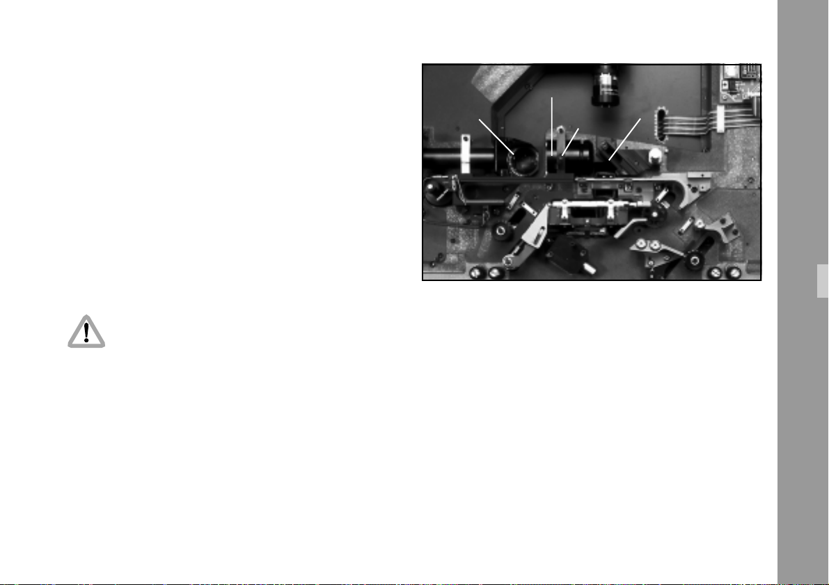
1) Pull off the control knobs ➪ photo.
2) Remove all four screws ➪ photo with hex. socket
wrench SW3 and carefully lift off optics’ cover.
Attention!:
Ensure that BNC and S-VHS plugs are not
damaged.
lens
mirror
lens yoke
5) Take out lens ➪ photo. Clean front- and rear lens
with lens cleaning tissue.
6) Re-insert lens.
mirror
3) Remove dust from mirrors 1 and 2 ➪ photo, using
lens cleaning brush and, if necessary, lens cleaning
tissue and some alcohol.
4) Push lens yoke ➪ photo to the left out of its lock and
swing away.
7) Ensure that the driver pin catches in the lens groove.
8) Swing lens yoke into position and lock.
9) Carefully reattach optic cover and fasten with four
screws.
10)Reattach control knobs.
Service and Maintenance
47
Page 48
7.3 Shipping and Storage
7.4 Replacing the Fuses
1) Put shipping safety label onto right film plate and
screw in shipping safety screw while the film channel
is open.
2) The LOCPRO 35 should only be stored or transported
in the upright position and in its original packing.
Service and Maintenance
Before replacing blown fuses, first eliminate the cause.
See Annex - Trouble Shooting List
Before replacing fuses, the LOCPRO 35 must be
completely disconnected from the mains.
Follow the safety and warning instructions in
the user manual.
When lifting off the optic cover do not damage
BNC and S-VHS plug.
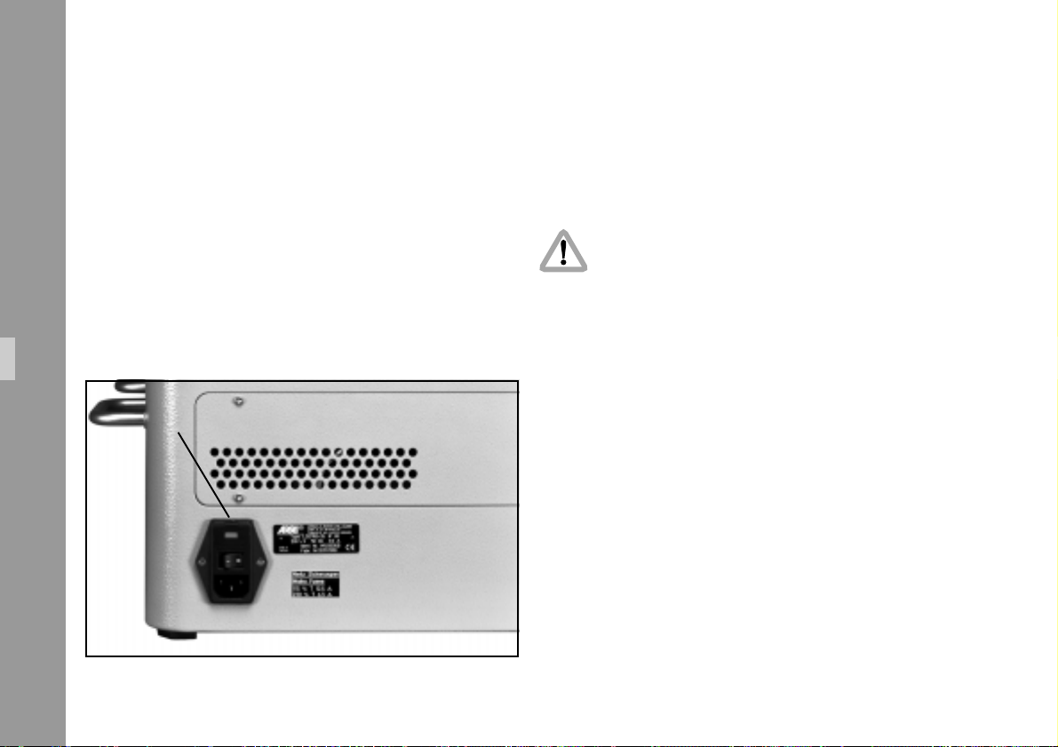
The main fuses located in the main power socket are
accessible from the outside.screw driver
48
Page 49
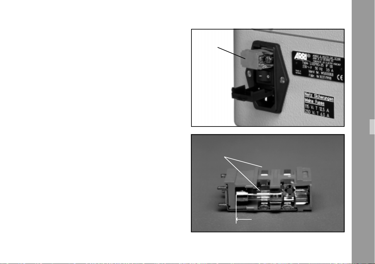
• Open down the hinged flap ➪ photo on the socket,
using a small screwdriver, and remove the fuse holder
➪ photo.
Fuses Primary Circuit (Mains)
• 2 fuses in main power socket
115 V ................................ Type 5x20, 2 x T 12.5 A
230 V .................................. Type 5x20, 2 x T 6.3 A
Note: When replacing 230 V fuses, make sure (glass
tube 5 x 20 mm EURO) to slide the fuses all the
way up to the front, as otherwise no electrical
contact is made ➪ photo.
fuse set
fuse
Service and Maintenance
49
Page 50

50
Page 51

8. Technical Data
Projection lamp ......................... 400 W HTI-lamp Id.No. M5.81802.0
Projector type............................ LOCPRO 35 St/ LOCPRO 35 TV
CE certificate ............................ Guideline 89/336 EEC of 3. May 1989
“Guideline of the Council of 3. May 1989 for bringing into line the statutory regulations of the member
countries about electromagnetic side-effects.”
Guideline 73/23 EEC of 19.02.73
“Guideline of the Council of 19. Feb. 1973 for
bringing into line the statutory regulations of the
member countries with respect to electrical
operating material for use within particular
voltage limitations.
Film format ............................... 35 mm negative/positive perforation
according to DIN 15501/ISO 491-1983
Filmgate ................................... 18.6 x 24 mm, selectable via format masks
Lens .......................................... F2/50 mm
Film capacity ............................ 300 m / 1000 ft
With 50 and 75 mm film core
Film core .................................. 50/75 and 100 mm selectable
Weight ..................................... approx. 56 kg
Dimensions ............................... 740 mm (w)x700 mm (d)x510 mm(h)
Wall projection ......................... 2300 mm (w) at 12 ft distance to wall
(see separate data sheet)
Projection rates ......................... 50 Hz operation 50, 25, 12.5, 6.25, 3.12, 1.56 fps
60 Hz operation 60, 30,15, 7.5, 3.75, 1.87 fps
Cine mode 48, 24, 12, 6, 3, 1.5 fps
Telecine mode 24, 25, 30 fps
with timecode output
Pulldown mode 23.976 fps (mode 24/60)
with timecode output
Single frame: ............................ Forward/reverse
Image steadiness:...................... < 0,2%
HS shuttle/rewind: .................... 200 fps forward and reverse
Operation conditions: ............... 10° to 40°C, 10-90% air humidity
Power supply: ........................... 180 – 253 V / 50 Hz, 90 – 127 V / 60 Hz
Technical Data
51
Page 52

Power consumption: .................. 230 V, 3.5 A / 115 V, 7 A
Computer interface: .................. RS 232, 8 Bit, no parity, one start and one
stop bit
Digital display: ......................... Frame counter, 5 digits
Projection speed
Set up Mode (selectable by “Mode” key),
unit configuration,
filmcore diam. selection,
film type selection
Frameline adjustment: ............... 1/4 image per keystroke
Technical Data
Auto-Stop: ................................ film run stops automatically 2 m (6 ft) before
end of film
Covering cap (optional)
Shipping and projection case (option)
ASU (Audio Sync Unit),
Timecode cable for DAT recorder (optional),
Image format masks (optional)
1/3” CCD-Color IMAGER
Signal system: ........................... PAL NTSC
Pixels: ....................................... 752 (H) x 582 (V) 768 (H) x 494 (V)
Scanning area: ......................... 6,0 mm x 4,96 mm 6,0 mmx 4,96 mm
Synchronization: ....................... internal internal
52
Auto winding recognition: ......... no switchover necessary when changing
winding direction A or B
Focussing: ................................. manually
Projection height adjustment: ..... max. 15°
Accessories: .............................. mains cable, maintenance tool kit,
Video camera (optional)
IR-remote control (optional)
Scanning system: ...................... 2:1 interlaced 2:1 interlaced
S/N ratio: ................................ 46 dB 48 dB
H/V resolution: ......................... 460 (TV) lines 470 (TV) lines
Video output: ............................ FBAS or Y/C FBAS or Y/C
Video masking: ......................... freely adjustable freely adjustable
Page 53

Serial Interface (X1)
An ASCII terminal or a personal computer with terminal
emulation program can be connected to the serial interface.
This makes it possible to check and change the operating
parameters.
Some image processing programs allow the integration of
control commands which are transmitted to the serial
interface.
Connection of PC or terminal via 1:1 connected interface
cable (no zero modem cable, no crossed connections).
Setting values
of serial computer interface
Baud rate: ................................ 9600 Baud/S
Data format: ............................. 8 bit, no parity, one start- and one stop bit
Plug type: ................................. 25 pin D-sub socket
Pin configuration:...................... see annex ”Interfaces”
Command Outline
RFX .......................................... Run Forward
Function:
Forward running at selected projection speed.
Parameters (50 Hz Version)
X =0123456
fps 50 25 12.5 6.25 3.12 1.56 0
Parameters (60 HzVersion)
X =0123456
fps 60 30 15 7.5 3.75 1.87 0
Note: This applies only for standard settings (50/50 and 60/60). If these are
changed by “Mode” function (Telecine Mode or Pulldown Mode) then
this frame rate is dominating. See Chapter 6.4.2.
RRX .......................................... Run Reverse
Function:
Reverse running at the selected projection
speed
Parameters 50 Hz and 60 Hz version see table
RFX.
Technical Data
53
Page 54

WF ........................................... Wind Forward
Function:
Highspeed shuttle at 200 fps (forward)
WR ........................................... Wind Reverse
Function:
Highspeed shuttle at 200 fps (reverse)
SF ............................................ Single Frame Forward
Function:
Advance one frame
OI ............................................ Output Instruction Code
Function:
System identification code of LOCPRO 35 is
displayed on the screen LOCPRO-35-01
OO .......................................... Output Option
Function:
The mains frequency set on the
LOCPRO 35 is displayed on the screen.
0000 = 50 Hz
0100 = 60 Hz
SR ............................................ Single Frame Reverse
Technical Data
OC ........................................... Output Counter-Value
OF ........................................... Output whether a film is loaded
54
Function:
Reverse one frame
Function:
The frame counter value of the LOCPRO 35 is
displayed on screen.
Function:
Inquiry to the LOCPRO 35 whether a film is
loaded in the unit.
Screen output: 1 = loaded
0 = not loaded
OR ........................................... Output Run or Stop
Function:
Inquiry to the LOCPRO 35 whether the film is
transported.
transported = 1
not transported = 0
OV ........................................... Output Version No.
Function:
EPROM version number is displayed on the
screen
Page 55

9. Trouble-Shooting Table
This trouble-shooting table serves the user and the service
engineer as an aid for locating and correcting possible faults.
The following must be strictly observed:
• The LOCPRO 35 must be disconnected from
the main power before starting any service
or repair jobs, and all interface connections
must be removed.
• The safety and warning notes contained in
the operating and service manuals must be
strictly followed.
• Ensure that the BNC- and S-VHS plugs are
not damaged when removing the optics
cover.
Tools and adjusting devices required for service and
repair are described in the Service Manual.
Note: In the following the test computer is referred to
as “Laptop”. However, a PC with suitable
emulation program can also be used.
Trouble-Shooting
55
Page 56

Fault Cause Remedy
Mains “ON” without function Mains voltage failure? Connect to another electrical socket
unit will not operate and check.
Mains cable connected to projector? Check mains connection
and replace mains cable if necessary
Primary fuses defective Replace fuses
(F1, F2, mains socket) (see service instructions)
Projector voltage different from mains voltage Check mains voltage setting on name plate.
If different from actual mains,
have service engineer make necessary change.
Important: Change name plate!
Trouble-Shooting
Rotating shutter not operating “E152” Lamp cover not in position Attach lamp cover, and clean
or safety switch not actuated. actuation opening for safety switch
Temperature sensor in lamp housing Switch on unit for cooling
has responded (without switching on HTI lamp).
Inform ARRI-Service-Workshop
Allow 2 minutes for cooling off,
then briefly switch off and on
with mains switch. Ignite HTI lamp again.
56
Page 57

Fault Cause Remedy
Projector does not work with IR Projector not switched on? Switch on projector.
Remote control
Low remote control battery? Replace battery.
IR-window on front of projector Make IR-window accessible for transmitter pulse.
is screened off by obstacles in room?
Battery in remote control is placed in wrong direction (reversed polarity) Insert battery correctly and try again.
IR-remote control defective Call ARRI Service station.
Image runs out of focus Jet underneath film gate clogged. Remove foreign matter.
when switching over from still
to motion picture (and vice-versa) Blower break-down. Call ARRI Service station.
Guide vane misadjusted. Call ARRI Service station.
Positive film has scratches Emulsion buildup in film gate. Clean emulsion deposits from film gate
on emulsion side in picture area using ARRI plastic scewer.
Film gate damaged by stapled film. Call ARRI Service station.
Negative film has scratches Emulsion buildup on pressure pad of film stage Remove emulsion deposit from pressure pad,
on emulsion side in picture area using ARRI film track cleaning scewer.
Trouble-Shooting
57
Page 58

Fault Cause Remedy
Scratches in film perforation area Emulsion buildup on film guiding parts. Clean film guiding parts
in accordance with maintenance instructions.
Film guide runners damaged, surface worn through. Call ARRI Service station.
Pressure pad damaged Call ARRI Service station.
by stapled film
Scratches on film backing side Emulsion deposits on pressure pad or on film gate Clean pressure pad and film gate
Positive and negative film in accordance with maintenance instructions.
Pressure pad jamming. Call ARRI Service station.
Trouble-Shooting
HTI-Lamp dark after ignition HTI lamp not properly installed Check HTI Lamp plug for correct locking
(experienced personnel only)
Defective lamp Replace lamp (experienced personnel only)
Ballast not functioning Call service engineer
58
Page 59

Fault Cause Remedy
HTI lamp dark after ignition Thermofuse in ballast Switch on unit for cooling
or in lamp housing has reacted (without switching on HTI lamp).
Allow 2 minutes for cooling off, then briefly switch
off and on with mains switch. Re-ignite HTI lamp.
Ventilation fans not operating Call service engineer.
HTI-Lamp “ON” but not functioning Master Control Knob not in “0” position Turn Master Control Knob to “0” position
Electronics disturbed Carry out mains reset.
Switch unit off for approx. 30 seconds.
Then switch on again and start new ignition attempt.
If this fails, call service engineer.
HTI lamp defective Replace HTI lamp
(experienced personnel only).
Fuse defective Call service engineer.
Keyboard illumination and/or display dark Control voltage failure Call service engineer
Trouble-Shooting
59
Page 60

Fault Cause Remedy
Film channel Foreign matter in film channel. Remove obstacle
“OPEN/CLOSE” function disturbed Film loop cannot be formed and actuate “Film” key once again.
Film not properly inserted Tension film slightly on both film plates
with film channel open.
Film must drop totally to bottom of film channel.
Lamp cover not properly seated Check film channel slide on lamp cover
or distorted for easy running. If sluggish, replace
and lock lamp cover with film channel open.
If this fails, call Service Engineer.
Loop sensor dirty; Clean with ARRI maintenance tools.
Trouble-Shooting
Sudden stop during film transport Film loop monitor switch has detected Open and close film channel. Repeat film transport.
Reflex light barrier
on left loop box
doesn’t detect film loop.
Electronic board defective Call ARRI Service station
improper splicing or stapled film In case of stapled film remove staples
and replace by splicing.
Then check pressure pad and film guiding elements
for possible damage.
60
Page 61

Fault Cause Remedy
Sudden stop during film transport Loop sensor and reflex protector Clean with ARRI maintenance tools.
on left loop box dirty
with film dust.
Emulsion build-up in film channel. Remove emulsion build-up from film pressure stage,
film track, deflection runner 1 and 2 and from film
pressure plate, using ARRI maintenance tools.
Operation too noisy Improper length of film loop. Open film channel and slightly tension film loop
manually by turning the two winding plates.
Then close film channel.
If fault still exists, call service engineer.
Film transport speed malfunctioning Setting on master control knob Call ARRI Service station.
doesn’t correspond to selected frame rate.
Autostop malfunctioning Wrong film core. Use correct film core diameter.
Film core diameter must correspond
to the one selected in
“Mode” function (Bobby Size).
Trouble-Shooting
61
Page 62

Fault Cause Remedy
No video image Operator error Shift slide switch “Video” to TV position.
Swing mirror out of optical path with video knob.
Connect unit with monitor.
Set correct channel selection on monitor.
Close film channel. Ignite HTI lamp.
Video camera defective Call ARRI service station.
Trouble-Shooting
62
Page 63

Error Messages in Display
Fault Cause Remedy
E-No. 102 > Foreign matter in film channel area. Take off lamp cover and remove foreign matter.
Carriage cannot be moved.
Carriage jamming. Call ARRI Service station.
Control error Call ARRI Service station.
E-No. 104> Foreign matter in film channel area. Take off lamp cover and remove foreign matter.
Carriage cannot be totally opened.
Check mechanism of film track 2
and of deflection runner 2 for movability.
Electric breakdown. Call ARRI Service station.
E-No. 106> Film jamming in film channel Remove foreign matter.
No loop forming possible by main motor. caused by foreign matter.
Film winding plate jamming. Call ARRI Service station.
Motor or electronics defective Call ARRI Service station.
Trouble-Shooting
63
Page 64

Fault Cause Remedy
E-No. 108 > See E-No. 102 See E-No. 102.
Carriage doesn’t close properly.
Shipping safety screw screwed in Remove shipping safety screw.
E-No. 110 > See E-No. 102 See E-No. 102.
Carriage doesn’t close or closes too slowly.
E-No. 112 > See E-No. 102 See E-No. 102.
as E-No. 108 Dual loop almost completed.
E-No. 114 > Film chips or splicing tape chips in film channel Remove chips, clean film guide parts and remove
Dual loop cannot be completed. or film emulsion deposits emulsion deposits.
on film guide parts.
Trouble-Shooting
E-No. 120 > See E-No. 102 See E-No. 102.
Film channel cannot be closed completely.
E-No. 122 > See E-No. 114 See E-No. 114.
Last frame of dual loop
cannot be totally pulled in.
E-No. 124 > Control error. Repeat procedure several times.
Film channel opens again If fault still exists after several attempts
slightly after closing. (indicated by E-No. 124) call ARRI Service station.
64
Page 65

Fault Cause Remedy
E-No. 132 > Foreign matter at deflection runner 2. Remove foreign matter.
Film channel opens again slightly
after closing, loop not completed.
E-No. 138 > See E-No. 132. See E-No. 132.
as E-No. 132, however, loop completed.
E-No. 142 > Foreign matter in film channel. Open film channel and remove foreign matter.
Main motor jamming during projection. Check film track for possible damage.
Poor film splices. Splice film properly and reinsert film.
Film sprocket roller jamming. Take out film. Switch off mains switch.
Take off lamp cover and
carefully turn film sprocket roller by hand.
If it doesn’t turn,
call ARRI Service station.
Motor jamming. Call ARRI Service station.
E-No. 144 > See E-No. 142 See E-No. 142
Motor jamming during rewinding.
Trouble-Shooting
E-No. 146 > See E-No. 142 See E-No. 142 See E-No. 142
65
Page 66

Fault Cause Remedy
E-No. 148 > Foreign matter in film channel. Open film channel and remove foreign matter.
Feed and take-up motor jamming
during projection. Defective belt. Check winders for turnability.
If they can be turned independently
from each other, call ARRI Service station.
Feed and take-up motor drive jamming. Call ARRI Service station.
Film winding plate jamming. Remove obstacle.
Winding motor defective. Call ARRI Service station.
E-No. 150 > See E-No. 148 See E-No. 148
Trouble-Shooting
Feed and take-up motor jamming during rewinding.
E-No. 152 > Lamp cover not placed in position Attach lamp cover or clean actuation opening
Shutter motor not running. or safety switch not actuated. for safety switch.
Revolving shutter jamming because of foreign matter. Remove foreign matter or call ARRI Service station.
Shutter motor defective. Call ARRI Service station.
Video camera defective at video “ON”. Test function with video “off”.
No sync signal for revolving shutter. Otherwise call ARRI Service Station.
66
Page 67

Fault Cause Remedy
E-No. 154 > Electronic board defective. Switch LOCPRO 35 on and off.
Faulty location correcting data. If location correcting data still faulty
call ARRI Service station.
E-No. 156 > Battery-RAM defective. Call ARRI Service station.
Frame counter data lost
when LOCPRO 35 is switched off.
Trouble-Shooting
67
Page 68

10. ARRI Service
Germany ............................... Arnold & Richter Cine Technik
Türkenstraße 89
D-80799 München
Phone (089) 3809-0
Fax (089) 3809-1244
Fax Service (089) 3809-1793
USA........................................ARRI USA
ARRI Service
GB ........................................... ARRI (GB) Ltd.
617, Route 303
Blauvelt, New York 10913
Phone (914) 353 14 00
Fax (914) 425 12 50
ARRI USA
600 North Victory Blvd.
Burbank, California 91502
Phone (818) 841 70 70
Fax (818) 848 40 28
The Movie House
1-3 Airlinks, Spitfire Way
Heston TW5 9 NR
Phone (0208) 848 88 81
Fax (0208) 561 13 12
Italy ........................................ ARRI ITALIA S.R.L.
Viale Edison 318
20099 Sesto S. Giovanni,
Milano
Phone (02) 26 22 71 75
Fax (02) 242 16 92
ARRI ITALIA S.R.L.
Via Placania, 97
00040 Morena (Roma)
Phone (06) 79 89 02 02
Fax (06) 79 89 02 39
Canada .................................. ARRI Canada Ltd.
415 Horner Avenue, Unit 11
Etobicoke, Ontario
Canada M8W 4W3
Phone (416) 255 33 35
Fax (416) 255 33 99
68
Page 69

11. Index
B
50 Hz Projector, Frame Rate Selection.................... 34
50 Hz/60 Hz Version .......................................... 23
60 Hz Projector, Frame Rate Selection.................... 34
A
Accessories ......................................................... 52
Additional Items..................................................... 9
Adjusting Knob Video .......................................... 40
Adjusting Lever .................................................... 22
Aperture Size ......................................................13
ARRI Service Workshops ....................................... 68
ASU .............................................................. 7, 44
Audio Sync Unit ............................................. 7, 44
Auto Winding Recognition ............................... 7, 52
Automatic End Stop ............................................. 37
Autostop ...................................................... 24, 52
Autostop Function ................................................ 25
Disabling ...................................................... 25
Enabling ....................................................... 25
Film Core Setting............................................ 25
Reactivating................................................... 25
Batteries ............................................................. 15
Baud Rate ........................................................... 53
Biphase ..............................................................44
BNC Socket ........................................................ 20
BNC-Cable ......................................................... 12
Bobby Size Selecting ........................................... 35
C
Cable
BNC ............................................................. 12
Y/C.............................................................. 12
CCD Color Video Camera ...................................... 7
CCD-Color IMAGER ............................................. 52
CCD-Video Camera .............................................52
CE Certificate ...................................................... 51
CE-Guidelines ....................................................... 5
Cine Mode ........................ 30, 32, 34, 41, 42, 43
Cleaning
Film Track...................................................... 45
Lens .............................................................. 47
Mirror ........................................................... 47
Optical Surfaces .............................................. 6
Index
69
Page 70

Color Temperature ................................................. 8
Command Outline ............................................... 53
Computer
for Image Processing ...................................... 20
Index
Interface........................................................ 52
Contamination....................................................... 6
Control Commands Integrating .............................. 53
Control Knob Focus.............................................. 40
Cooling Fan ........................................................ 10
Core Diameter Selecting ....................................... 35
Crossline ............................................................ 21
D
DAT-Recorder ...................................................... 12
Data Format ........................................................ 53
Decimals in Display ............................................. 31
Deflection Runner................................................. 46
Deposits ............................................................... 6
Dimensions ......................................................... 51
Display............................................................... 52
Dark Bar ....................................................... 33
Decimals ....................................................... 31
Dot ............................................................... 24
Error Messages .............................................. 63
Normal ......................................................... 33
Distances
for Cooling.................................................... 10
for Wall Projection ........................................... 9
Dot in Display ..................................................... 24
Dust ................................................................... 47
E
Emulsion Deposits ........................................... 6, 46
Emulsion Side...................................................... 18
End Stop
Disable Automatic .......................................... 37
Enable Automatic ........................................... 37
Error Messages ................................................... 63
Ext Synchro......................................................... 43
F
Factory-loaded Film Types..................................... 35
Fast Film Transport .................................................7
FBAS Socket........................................................ 20
Feed Carriage..................................................... 18
Film Capacity ...................................................... 51
Film Channel ....................................................... 18
Close ............................................................ 37
Open............................................................ 37
70
Page 71

Film Core..................................................... 18, 51
Diameters...................................................... 51
Film Format ......................................................... 51
Film Gate Format Mask Exchanging ....................... 13
Film Gate Mask Set.............................................. 13
Film Key .................................. 18, 21, 24, 29, 37
Film Loop ............................................................ 18
Automatic...................................................... 18
Film Plate ............................................................ 18
Film Rolls ............................................................ 18
Film Track ...........................................................46
Film Type Selecting .............................................. 35
Film Types Factory-loaded..................................... 35
Filmcore Size ...................................................... 35
Filmgate ............................................................. 51
Focus ................................................................. 22
Knob ............................................................ 22
Focussing............................................................ 52
Format Mask
Inserting ........................................................ 13
Removing ...................................................... 14
Frame Line ..........................................................21
Frame Line Adjustment.......................................... 37
Frame Line Shifting............................................... 42
Frame Rates ........................................................ 23
Fixing ........................................................... 33
NTSC-Video Camera ......................................31
PAL-Video Camera.......................................... 30
Selecting ....................................................... 33
Standard 50 Hz Version.................................. 23
Standard 60 Hz Version.................................. 23
with PAL/NTSC Video..................................... 31
with PAL/NTSC Video Display ......................... 31
Frame Rates Selection .......................................... 38
50 Hz Projector ............................................. 34
Frameline Adjustment ........................................... 52
Fuses
Primary Circuit ............................................... 49
Fuses Primary Circuit ............................................ 49
G
Glue Residues ....................................................... 6
Index
71
Page 72

H
H/V Resolution .................................................... 52
Highspeed Shuttle ................................................ 23
Highspeed Winding............................................. 42
Index
HTI Lamp ............................................................ 51
Average Life ..................................................17
Ignition .................................................. 17, 39
Replacing...................................................... 80
Runup Time.................................................... 17
Spare Lamp ................................................... 17
Switching Off ................................................ 17
Switching On................................................. 17
Working Temperature ..................................... 17
I
IEC ...................................................................... 5
Ignition
HTI Lamp....................................................... 17
Image Position..................................................... 22
Lever ............................................................ 40
Image Processing Computer .................................. 20
Image Steadiness................................................. 51
Evaluation ..................................................... 26
Infrared Remote Control................................. 15, 41
Initial Operation .................................................. 11
Inside Winding.................................................... 18
Installation ............................................................ 9
Integration of Control Commands .......................... 53
Interfaces ............................................................ 79
Biphase......................................................... 44
Cable ........................................................... 12
Ext. Synchro .................................................. 43
LTC ............................................................... 44
Serial..................................................... 43, 53
Timecode ...................................................... 44
IR-Receiver .......................................................... 15
IR-Remote Control ......................................... 15, 41
IR-Transmitter ....................................................... 15
K
Key
FILM .................................. 18, 21, 24, 29, 37
LAMP..................................................... 17, 39
MODE .............................................23, 29, 38
RESET .................................................... 29, 39
Knob
FOCUS .................................................. 22, 40
Master Control........................... 21, 23, 24, 36
VIDEO ................................................... 19, 40
72
Page 73

L
Lamp.................................................................. 51
Cooling Fan .................................................. 10
Cover ........................................................... 45
Lamp Key .................................................... 17, 39
Lens ................................................................... 51
Cleaning ....................................................... 47
Lever Image Position............................................. 40
Loop Box ............................................................ 46
Loop Forming ......................................................27
LTC .................................................................... 44
M
Main Fuses ......................................................... 48
Main Power Socket .............................................. 48
Mains Switch ............................................... 16, 36
Masking
Setup ............................................................ 33
Video .................................................... 38, 52
Master Control Knob ................. 17, 21, 23, 24, 36
Mirror ......................................................... 12, 19
Cleaning ....................................................... 47
Mirror Setting Knob ............................................. 12
Mode
Cine ............................................................. 32
Pulldown .......................................................32
Telecine......................................................... 32
Mode 1 ....................................................... 33, 38
Mode 2 ....................................................... 33, 38
Mode 3 ....................................................... 34, 38
Mode 4 ....................................................... 35, 38
Mode Key.............................................. 23, 29, 38
Monitor .............................................................. 20
Monitor Socket ....................................................20
N
Negative Film...................................................... 18
Negative Perforation ............................................ 27
Normal Display View ........................................... 33
Normal Mode ..................................................... 43
Normal Viewing Mode......................................... 38
Notes, important.................................................... 6
NTSC-Video Camera..................................... 19, 31
Index
73
Page 74

O
Operation
Single Frame ................................................. 24
Operation Conditions........................................... 51
Index
Operation Modes ................................................ 32
Optics Cover....................................................... 46
Output Video ...................................................... 52
Outside Winding ................................................. 18
P
Packing Straps ...................................................... 9
PAL Video Camera........................................ 19, 30
Parameter ...........................................................53
PC Connection .................................................... 53
Perfotape Player .................................................. 12
Picture Steadiness, poor ......................................... 6
Pixels ................................................................. 52
Positive Film ........................................................ 18
Positive Perforation .............................................. 27
Power Consumption ............................................. 52
Power Supply ...................................................... 51
Product Identification .............................................. 6
Projection
Sprocket........................................................ 26
Stop/Still....................................................... 42
Projection Case ..................................................... 9
Projection Formats ............................................... 13
Projection Height
Adjusting ............................................... 22, 52
Projection Lamp ................................................... 51
Projection Rates ...................................................51
Pull Down Mode ................................ 8, 32, 34, 42
R
Remote Control
Frame Line Shifting .........................................42
Highspeed Winding .......................................42
Single Frame ................................................. 42
Start ............................................................. 41
Stop/Still Projection ........................................ 42
Reset Key..................................................... 29, 39
Residues ........................................................ 6, 46
Revolving Shutter ................................................. 30
Rewinding High Speed........................................... 7
Runout ................................................................ 25
Runup Time HTI Lamp ........................................... 17
74
Page 75

S
S-VHS Socket ...................................................... 20
S/N Ratio........................................................... 52
Safety Label ........................................................ 48
Safety Screw ................................................ 11, 48
Safety Specifications
Attention ......................................................... 5
Caution........................................................... 5
Note............................................................... 5
Scanning Area .................................................... 52
Scanning System ................................................. 52
Screws
paint secured................................................... 6
Selection Knob .................................................... 19
Serial Interface ............................................. 43, 53
Service ...............................................................68
Service Instructions............................................... 80
Setting Knob ....................................................... 12
Mirror ........................................................... 12
Setting Values...................................................... 53
Setup Masking .................................................... 33
Setup Speed ....................................................... 34
Shipping............................................................... 9
Shipping Case ...................................................... 9
Shipping Safety Measures .................................... 11
Shipping Safety Screw ......................................... 11
Shutter Synchronization ........................................ 43
Shuttle ................................................................23
Single Frame ....................................................... 42
Single Frame Left ................................................. 37
Single Frame Operation ....................................... 24
IR-Control ...................................................... 24
left................................................................ 24
right ............................................................. 24
Single Frame Right ............................................... 37
Slide Switch ................................................. 12, 19
Video ........................................................... 12
Slide Switch Video ............................................... 40
Socket
S-VHS ...........................................................20
Y/C.............................................................. 20
Socket Main Power ..............................................48
Solvents ................................................................ 6
Sound Synchronization........................................... 8
Spare Lamp ........................................................ 17
Speed ................................................................ 23
Setup ............................................................ 34
Sprocket
Quality ......................................................... 26
Sprocket Projection .............................................. 26
Stapled Film ........................................................ 18
Index
75
Page 76

Start
with Remote Control ....................................... 41
Steadiness
Poor Picture .....................................................6
Stop/Still Projection ............................................. 42
Index
Switch Video Slide ............................................... 19
Symbols
Explanation .....................................................6
Sync Signals ......................................................... 7
Synchronization.......................................... 7, 8, 44
DAT-Recorder................................................... 7
Perfotape Player........................................ 7, 44
Shutter .......................................................... 43
Video ........................................................... 30
T
Telecine Mode ............................ 8, 32, 34, 41, 43
Temperature, differents ........................................... 9
Timecode............................................................ 44
Signal ........................................................... 44
Transfer ..............................................................44
Starting ......................................................... 44
Trouble-Shooting.................................................. 55
TV Symbol ................................................... 12, 19
TV-Monitor .......................................................... 12
U
Unit Configuration ............................................... 38
Unpacking ............................................................9
V
Ventilation............................................................. 6
Versions of LOCPRO 35 ......................................... 8
Video ................................................................. 12
Camera ................................................. 19, 52
Camera H/V Resolution .................................. 52
Camera NTSC ........................................ 19, 31
Camera PAL ........................................... 19, 30
Camera Starting Operation .............................19
Camera Synchronization................................. 52
Image Masking .............................................. 29
Knob ............................................................ 40
Masking................................................. 38, 52
Masking the Video Images .............................. 29
On/Off Switching .......................................... 12
Operation ..................................................... 30
Operation Switching On/Off........................... 30
Output ................................................... 20, 52
Printer ........................................................... 20
Recorder ....................................................... 20
Recorder Socket ............................................. 20
76
Page 77

S/N Ratio ..................................................... 52
Slide Switch...................................... 12, 19, 40
Sockets ......................................................... 20
Synchronization ............................................. 30
Video Selection Knob ........................................... 19
Video-Option ...................................................... 12
Viewing Mode
Normal ......................................................... 38
W
Wall Projection ............................................... 9, 51
Distance........................................................ 21
Warnings ............................................................. 5
Weight ...............................................................51
Winding
automatic Direction Recognition .........................7
Direction ....................................................... 18
Inside ........................................................... 18
Outside ......................................................... 18
Working Temperature of HTI Lamp ......................... 17
Y
Y/C Socket ......................................................... 20
Y/C-Cable .......................................................... 12
Index
77
Page 78

Index
78
Page 79
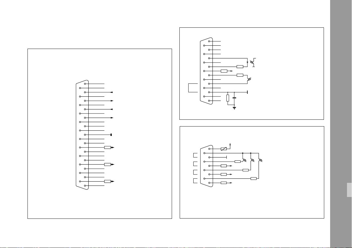
Annex Interfaces
Serial Interface
X1
DB 25
1
X
14
X
2
15
3
16
4
17
5
18
6
19
7
20
8
21
9
22
10
23
11
24
12
25
13
RXD
X
TXD
X
CTS
X
RTS
X
X
X
GND
X
X
1k
+15 V
X
X
X
1k
- 15 V
X
X
X
1k
+ 5 V
X
1
X
9
X
2
X
10
X
X2-3
3
11
X
FIP
4
12
5
13
6
14
7
15
8
Protecting Earth
1 k
X
X
X
1M 100 n
X
470
100
Bridge for LOCPRO 35 Potential
+ 24 V
100
1
6
X3ON
2
GND
7
3
8
4
9
5
Bridge for LOCPRO 35 Potential
100
BOP
+ 5 V
1 k
+ 5 V
1 k
+ 5 V
1 k
FOP
FON
100
Ext. Sync. Interface
X2
F-ext.
GND
FIP = Frequency Input positiv
FOP= Frequency Output positiv
FON= Frequency Output negativ
A/B u. LTC-Interface
X3
AOP
100
LTCOP
BOP = Canal B Output Positiv
AOP = Canal A Output Poistiv
LTCON = Timecode Output Positiv
X3ON = Output Negativ
DB 15
DB 9
Annex: Interfaces
79
Page 80
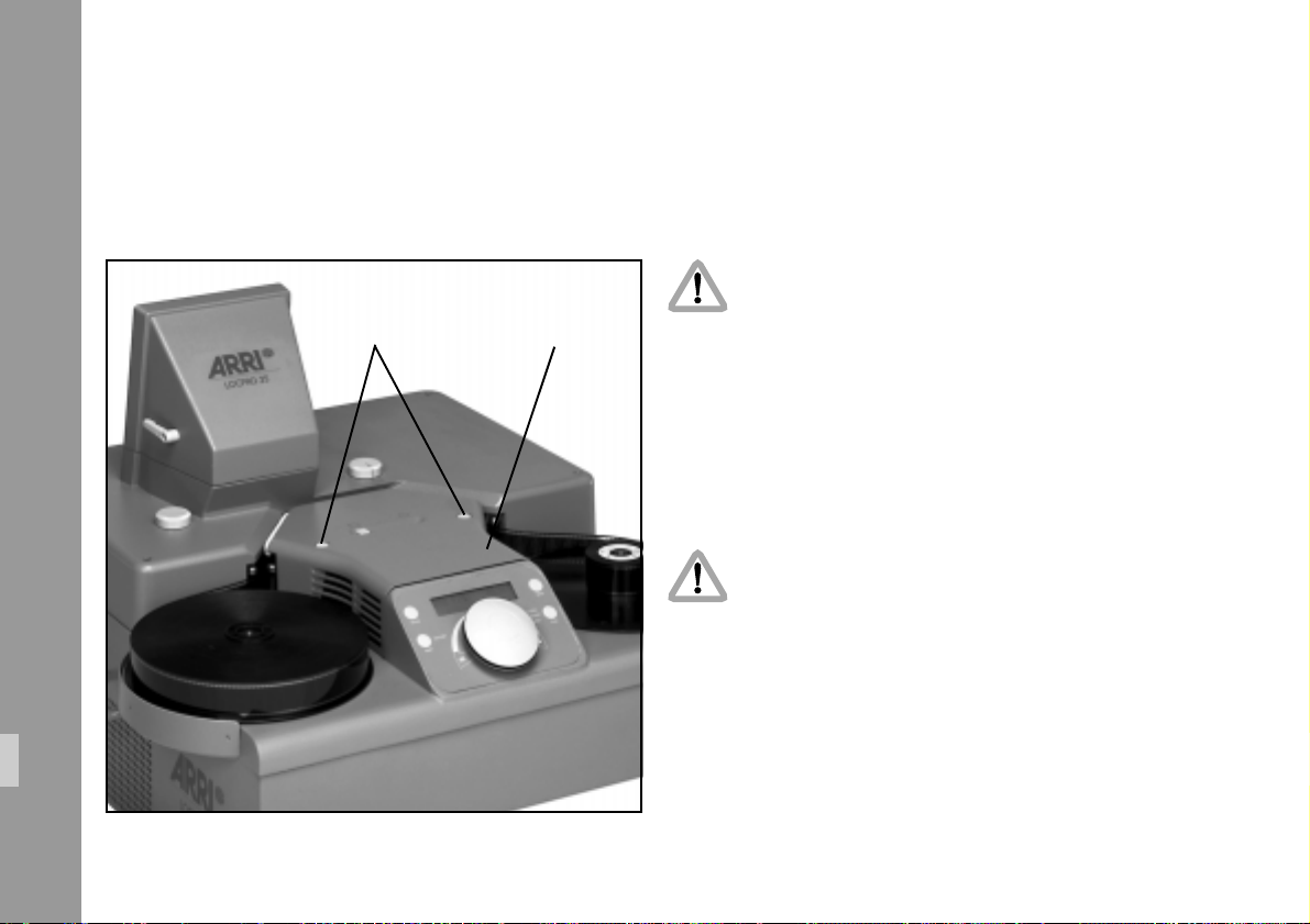
Service Instructions
Service work only by instructed personnel!
Caution: Danger of injury!
Before replacing of lamp allow approx.
snap locks lamp cover
Note: Cooling blower is only active when projector is
1) Disconnect LOCPRO 35 completely from mains.
2) Remove lamp hood.
2 minutes for cooling.
switched on.
Service Instructions
80
Caution: Danger of injury
After operation the metal plate hood covering
of the lamp housing is hot. To avoid burns
allow for cooling.
3) Open fixing screw of safety locking bar on plate hood
➪ photo with hex. Wrench 3 mm until safety locking
bar can be twisted by 90°. Swing away the plate
hood which covers the lamp housing.
Page 81
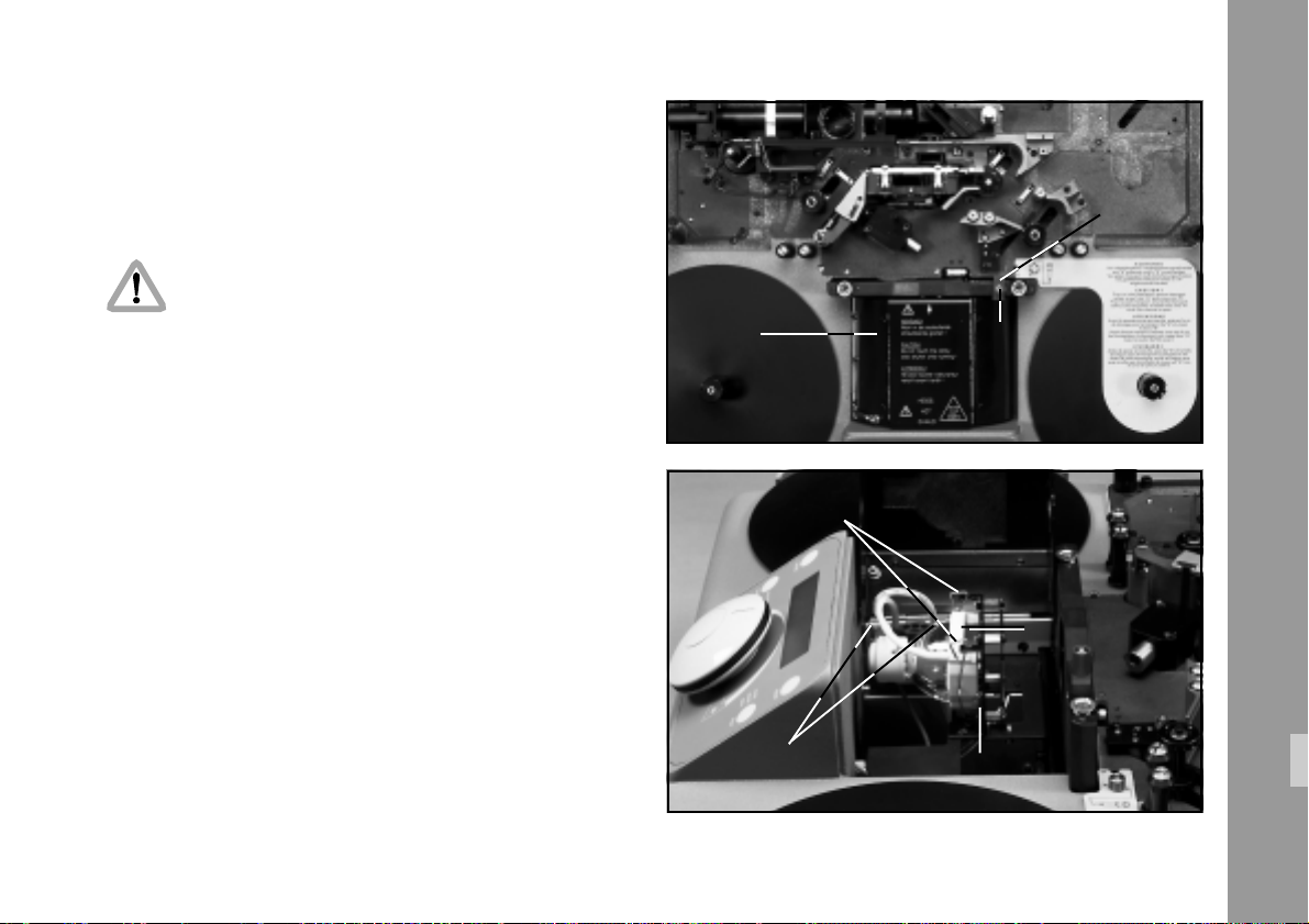
4) Depress both locking brackets on plug ➪ photo and
pull off plug ➪ photo.
5) Unhinge both spring levers ➪ photo.
Attention: To avoid fingersprints HTI lamp
should only be touched with appropriate gloves.
6) Pull out defective HTI lamp upwards
7) Insert new HTI lamp (Id.No. M5.81802.0) so that it
snaps-in with its twist protector at the bottom right and
sits flat on the lamp carrier (within the four centering
pins).
8) Arrest on catch with both spring levers ➪ photo.
9) Hold one hand against the plug plate and plug in the
plug with the other hand until the catch snaps in.
10)Close plate hood, twist safety locking bar in locking
position and screw on. Attach lamp hood and arrest
snap locks.
plate hood locking
screw
spring levers
locking brackets
twist protector
locking bar
Service Instructions
HTI-lampe
81
Page 82

Technical data are subject to change without notice.
© ARRI 1999
Ident. No. M5.81929.0
available languages
Deutsch
English
ARNOLD & RICHTER CINE TECHNIK
TÜRKENSTR. 89
FAX (089) 3809 - 1244 • http://www.arri.com
•
D-80799 MÜNCHEN • TEL. (089) 3809-0
 Loading...