

Page 1
Page 2

2 Single Motor Controller SMC-1 – User Manual
Version 09/2014
Page 3

Single Motor Controller SMC-1 – User Manual 3
Version 09/2014
Imprint
Copyright © 2014 Arnold & Richter Cine Technik GmbH & Co. Betriebs
KG. All rights reserved. No portions of this document may be
reproduced without prior written consent of Arnold & Richter Cine
Technik GmbH & Co. Betriebs KG. Specifications are subject to change
without notice. Errors, omissions, and modifications excepted. ARRI,
ALEXA are trademarks or registered trademarks of Arnold & Richter
Cine Technik GmbH & Co. Betriebs KG. All other brands or products are
trademarks or registered trademarks of their respective holders and
should be treated as such. Original version.
For further assistance:
ARRI Cine + Video Geräte Gesellschaft m.b.H.
Pottendorferstraße 25-27/3/1
A-1120 Vienna
Austria
E-mail: [email protected]
www.arri.com
Scope
This instruction manual applies to the following product: Single Motor
Controller SMC-1 with Software Update Package (SUP) 1.0
Document Information
Version
Document No.
Date
01
K5.0003468
10.09.2014
Page 4

4 Single Motor Controller SMC-1 – User Manual
Version 09/2014
Table of Contents
Disclaimer ........................................................................................... 6!
For Your Safety ................................................................................... 8!
Risk Levels and Alert Symbols ................................................... 8!
Vital Precautions ........................................................................ 9!
General Precautions ................................................................... 9!
Audience and Intended Use ....................................................... 9!
Introduction ....................................................................................... 10!
How to Use This Manual .......................................................... 10!
Scope of Delivery ..................................................................... 10!
System Requirements .............................................................. 10!
QUICK START GUIDE ....................................................................... 12!
Mounting on Camera ................................................................ 12!
Powering up ............................................................................. 12!
Setting up Motors ..................................................................... 12!
Connecting to Hand Unit .......................................................... 13!
Interfaces ........................................................................................... 14!
Control Panel .................................................................................... 16!
Soft Buttons .............................................................................. 16!
Menu Navigation ...................................................................... 16!
HOME ................................................................................................. 17!
Info Area ................................................................................... 17!
RADIO ................................................................................................ 18!
FOCUS/IRIS/ZOOM ........................................................................... 18!
MENU ................................................................................................. 19!
Axis ........................................................................................... 19!
Backlight ................................................................................... 19!
Firmware .................................................................................. 20!
System Info .............................................................................. 20!
Page 5

Single Motor Controller SMC-1 – User Manual 5
Version 09/2014
Appendix ........................................................................................... 21!
Antenna Connector .................................................................. 21!
Cables and Accessories ........................................................... 21!
Compatible Products ................................................................ 22!
Connector Pin-Outs .................................................................. 23!
Dimensions and Weight ........................................................... 25!
Electrical Data .......................................................................... 26!
Radio System ........................................................................... 26!
ARRI Service Contacts ............................................................ 27!
International Declarations and Certifications ............................ 28!
Page 6

6 Single Motor Controller SMC-1 – User Manual
Version 09/2014
Disclaimer
Before using the products described in this manual be sure to read and
understand all respective instruction.
The ARRI Single Motor Controller SMC-1 is only available to
commercial customers. The customer grants by utilization that the SMC1 or other components of the system are deployed for commercial use.
Otherwise the customer has the obligation to contact ARRI preceding
the utilization.
While ARRI endeavors to enhance the quality, reliability and safety of
their products, customers agree and acknowledge that the possibility of
defects thereof cannot be eliminated entirely. To minimize risk of
damage to property or injury (including death) to persons arising from
defects in the products, customers must incorporate sufficient safety
measures in their work with the system and have to heed the stated
canonic use.
ARRI or its subsidiaries do not assume any responsibility for incurred
losses due to improper handling or configuration of the SMC-1 or other
system components.
ARRI assumes no responsibility for any errors that may appear in this
document. The information is subject to change without notice.
For product specification changes since this manual was published,
refer to the latest publications of ARRI data sheets or data books, etc.,
for the most up-to-date specifications. Not all products and/or types are
available in every country. Please check with an ARRI sales
representative for availability and additional information.
Neither ARRI nor its subsidiaries assume any liability for infringement of
patents, copyrights or other intellectual property rights of third parties by
or arising from the use of ARRI products or any other liability arising
from the use of such products. No license, express, implied or
otherwise, is granted under any patents, copyrights or other intellectual
property right of ARRI or others.
Page 7

Single Motor Controller SMC-1 – User Manual 7
Version 09/2014
ARRI or its subsidiaries expressly exclude any liability, warranty,
demand or other obligation for any claim, representation, or cause, or
action, or whatsoever, express or implied, whether in contract or tort,
including negligence, or incorporated in terms and conditions, whether
by statue, law or otherwise. In no event shall ARRI or its subsidiaries be
liable for or have a remedy for recovery of any special, direct, indirect,
incidental, or consequential damages, including, but not limited to lost
profits, lost savings, lost revenues or economic loss of any kind or for
any claim by third party, downtime, good-will, damage to or replacement
of equipment or property, any cost or recovering of any material or
goods associated with the assembly or use of our products, or any other
damages or injury of the persons and so on or under any other legal
theory.
In the case one or all of the foregoing clauses are not allowed by
applicable law, the fullest extent permissible clauses by applicable law
are validated.
Page 8
8 Single Motor Controller SMC-1 – User Manual
Version 09/2014
For Your Safety
Always keep this document on hand. It should be read, understood and
observed by all persons using the Single Motor Controller SMC-1. All
other products must be handled as prescribed by their manufacturers.
Risk Levels and Alert Symbols
Safety warnings, safety alert symbols, and signal words in these
instructions indicate different risk levels:
This symbol alerts you to personal injury hazards or damage to
the equipment. Obey all warnings that follow this symbol to avoid
possible injury or death or damage to the equipment.
This symbol alerts you to electrical hazards. Obey all warnings
that follow this symbol to avoid possible injury or death.
DANGER!
Indicates an imminent, hazardous situation which, if not avoided, will
result in death or serious injury.
NOTICE: Explains practices not related to physical injury. The safety
alert symbol is not used with this signal word.
Note: Provides additional information to clarify or simplify a procedure.
Page 9

Single Motor Controller SMC-1 – User Manual 9
Version 09/2014
Vital Precautions
NOTICE: Read and follow all instructions before using the product. Use
the product only as described therein. Never open it. Never insert
objects.
Never attempt to repair the product: Always have it repaired and
serviced by authorized ARRI Service Centers.
Never remove or deactivate any product safety equipment (incl.
guarantee stickers).
Always protect the product from moisture, cold, heat, dirt, vibration,
shock, or aggressive substances.
General Precautions
Use only the tools, materials and procedures recommended in this
document. Unplug all cables during transport.
Do not store the SMC-1 in places where it may be subject to
temperature extremes, direct sunlight, high humidity, severe vibration, or
strong magnetic fields.
Audience and Intended Use
NOTICE: The product is solely and exclusively available for commercial
customers and shall be used by skilled personnel only. Always contact
ARRI preceding other uses. Every user should be trained according to
ARRI guidelines.
The SMC-1 is a motor controller solely and exclusively for iris, focus or
zoom control:
• Wireless via ARRI white radio modem
• Wired via ARRI LCS connection
Never use the product for any other purpose. Always follow the valid
instructions and system requirements for all equipment involved.
Page 10

10 Single Motor Controller SMC-1 – User Manual
Version 09/2014
Introduction
The Single Motor Controller SMC-1 is a compact 1-axis motor controller
designed for weight and size-critical setups such as Steadicam or
camera drones. It drives a single CLM motor and is the perfect
counterpart for the SXU-1 single-axis hand unit.
Visit www.arri.com/ecs/SMC-1 for up-to-date product information and
software updates.
How to Use This Manual
Connectors are written in all capital letters, for example, CLM.
Buttons are written in all capital letters, for example, MENU soft button.
Menus and screens are written in italic letters, for example Home
screen.
The appendix at the back of the manual contains useful reference
material including radio frequencies, spare parts and additional
accessories, connector pin-out diagrams and dimensional drawings.
Scope of Delivery
On delivery, please check if the package and its contents are intact.
Never accept a damaged/incomplete delivery. A complete delivery
includes:
• Single Motor Controller SMC-1, including antenna
• Instruction manual
• Original packaging
For scope of warranty, please ask your local ARRI representative. ARRI
is not liable for consequences from inadequate shipment, improper use,
or third-party products.
System Requirements
To tap the full potential of the device, have all connected units updated
to a firmware equal or higher to those listed below.
Page 11

Single Motor Controller SMC-1 – User Manual 11
Version 09/2014
Product
Firmware
Wireless Compact Unit WCU-4
SUP 1.2
Single Axis Unit SXU-1
SUP 1.0
Zoom Main Unit ZMU-3A
SUP 02G
Page 12

12 Single Motor Controller SMC-1 – User Manual
Version 09/2014
QUICK START GUIDE
This quick start guide walks you through setting up the SMC-1 with one
hand unit and one motor for wireless lens control.
Mounting on Camera
Mount the SMC-1 on the camera, preferably in a vertical position by
using the L-Bracket, with the antenna pointing upwards and the motor
connector pointing towards the lens. Such a position makes the SMC-1
user interface easily accessible.
Powering up
Connect the SMC-1 to a power source with one of the power cables
listed on page 21. The SMC-1 will power-up automatically when
connected to the power source.
Setting up Motors
Attach one CLM motor for focus, iris or zoom to the lens. Make sure the
motor is properly mounted to the respective lens axis and will not loosen
up when operated.
Connect the motor cable to the CLM connector on the SMC-1.
Set the SMC-1 to the lens axis it is connected to: Go to Menu>Axis and
select Focus, Iris or Zoom.
Go to the Focus, Iris or Zoom sub-page of the Home screen and press
CAL to calibrate the motor. You can also trigger calibration from the
hand unit.
Set up the motor mounting side and torque (if applicable) in the Focus,
Iris or Zoom sub-page (depending on the axis selection) of the Home
screen.
Side refers to the side of the lens the motor is mounted to (on standard
support rods underneath the lens).
Torque refers to the motor torque; a higher value means higher torque.
Page 13
Single Motor Controller SMC-1 – User Manual 13
Version 09/2014
Connecting to Hand Unit
Set the radio channel on the SMC-1. Press the RADIO soft button on
the Home screen and select a channel. Press SET to activate the
selected channel. Make sure that the selected radio channel is not
already in use by another motor controller.
Set the hand unit to the same radio channel (see the hand unit’s user
manual for further instructions). Once connected, the number of
connected hand units will change from 0 to 1 on the SMC-1 Home
screen.
You are now ready to shoot.
Note: After connecting a lens motor to the SMC-1 and the lens, it must
be calibrated. The lens motor must be recalibrated under the following
conditions:
• When the lens motor is detached from the lens
• After changing lenses
• After a change in motor position while powered down
Omitting motor calibration might lead to damage of the lens
due to the high level of motor torque!
Page 14
14 Single Motor Controller SMC-1 – User Manual
Version 09/2014
Interfaces
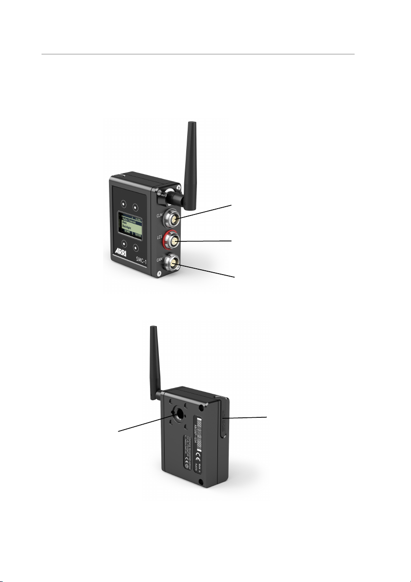
The SMC-1 includes the following interfaces:
CLM Motor
Connector
LCS
Connector
CAM
Connector
3/8” UNC-16
Mounting Point
Micro SD
Card Slot
Page 15

Single Motor Controller SMC-1 – User Manual 15
Version 09/2014
Interface
Description
Antenna
Swivel antenna
LCS Connector
Connects to hand units via ARRI LCS cable, for
wired operation
CAM Connector
Multi-pin connector, offering a variety of protocols,
providing REC and tally control for most film and
digital cameras
CLM Motor
Connector
Connects to an ARRI Controlled Lens Motor
Micro SD Card
Slot
Mounts a Micro SD card
3/8” UNC
Mounting Point
Mounting point for accessories like L-Bracket or VPlate
Page 16
16 Single Motor Controller SMC-1 – User Manual
Version 09/2014
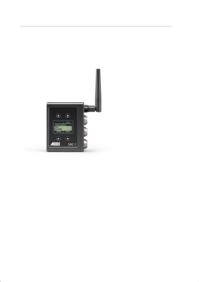
Control Panel
The SMC-1 features a user interface enabling the user to quickly
configure the system. The 1.2” transflective LCD display shows vital
status information and is easily readable in any ambient light conditions.
Fig. 1: Control Panel
Soft Buttons
Four soft buttons are located above and below the display. They change
their behavior depending on the screen content. Two rows at the top
and the bottom of the screen show the function related to each button.
Buttons without a label have no function in that screen.
Menu Navigation
Use the UP and DOWN soft buttons to navigate through the menu.
To access a new menu level, press the ENTER soft button. To go back,
press the BACK or the HOME soft button.
Press SET to activate a setting.
Page 17
Single Motor Controller SMC-1 – User Manual 17
Version 09/2014
HOME
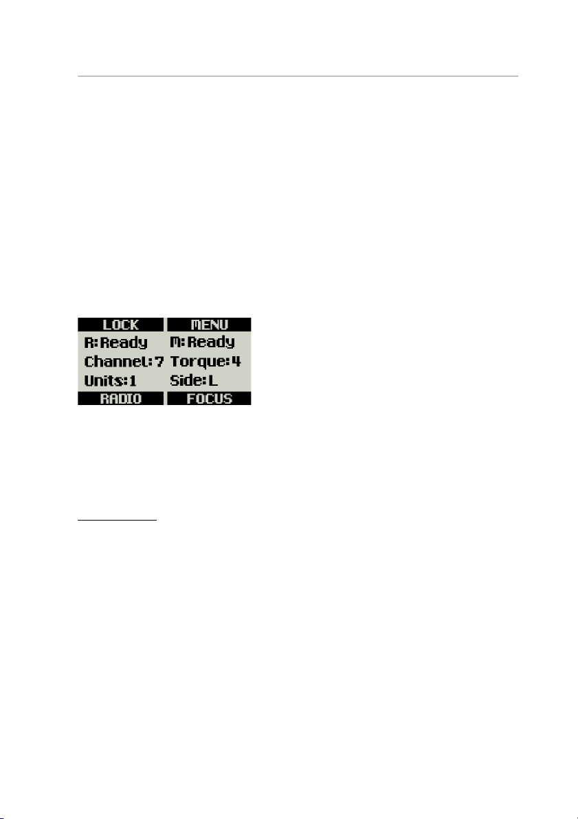
The Home screen is the default screen. It shows the current radio and
motor status.
The Home screen provides four soft buttons:
• LOCK: Press to lock or unlock the other three soft buttons. A
padlock symbol indicates that buttons are locked.
• MENU: Press to enter the main menu.
• RADIO: Press to select the radio channel.
• FOCUS/IRIS/ZOOM: Press to enter the motor setup menu.
Fig. 2: Home Screen
Info Area
The info area shows the current radio status on the left side of the
screen and the current motor status on the right side of the screen.
Radio Status
R:
Off
Indicates that the radio modem is switched off.
Init
Indicates that the radio modem is initializing.
Ready
Indicates that the radio modem is initialized and
ready to connect.
Blocked
Indicates that another motor controller is already
using the currently selected radio channel.
Select another radio channel!
Channel:
0 – 7
Indicates the radio channel.
Units:
0 – 3
Indicates the number of connected hand units.
Page 18
18 Single Motor Controller SMC-1 – User Manual
Version 09/2014
Motor Status
M:
CAL!
Please calibrate the motor!
CAL
Motor is calibrating.
Idle
The motor is not assigned to a control device.
Ready
The motor is ready to use.
None
There is no motor connected.
Torque:
1 – 4
Indicates the motor torque setting.
Side:
L/R
Indicates to which side of the lens the motor is
set (Left/Right).
RADIO
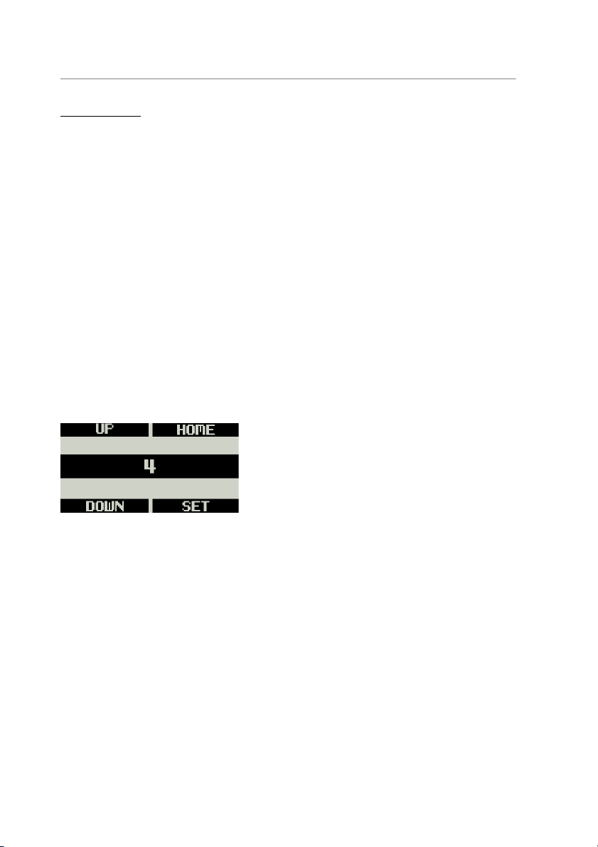
Press the RADIO soft button on the Home screen to enter the Radio
menu page. Use the UP and DOWN soft buttons to select the radio
channel or to switch the radio on and off. Select the same channel both
on the hand unit and the SMC-1.
Fig. 3: Radio Menu
FOCUS/IRIS/ZOOM
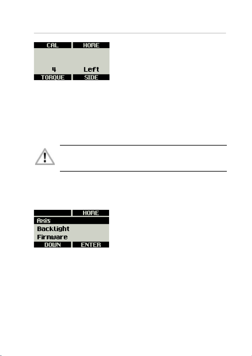
Press the FOCUS, IRIS or ZOOM (depending on the lens axis) soft
button on the Home screen to enter the motor menu page. The motor
menu lets you calibrate the motor and set up the motor torque and
mounting side.
Page 19
Single Motor Controller SMC-1 – User Manual 19
Version 09/2014
Fig. 4: Motor Menu
Press CAL to calibrate the current lens motor.
Press SIDE to select the side on which the motor is mounted to the lens.
Press TORQUE to set the torque level for CLM-3 and CLM-4 motors.
Torque setting is not available for the CLM-2 motor.
Ensure that the motor torque level matches the lens to avoid
lens damage. Stiff, hard-to-move lenses require a higher
torque level.
MENU
The Menu contains parameters for the basic SMC-1 setup.
Fig. 5: Main Menu
Axis
Select Focus, Iris or Zoom – depending on which axis you want to
control on the lens.
Backlight
Select the backlight brightness of the LCD screen. The brightness can
be set from 0 (backlight is off) to 10 (maximum brightness).
Page 20
20 Single Motor Controller SMC-1 – User Manual
Version 09/2014
Firmware
To keep your SMC-1 up-to-date, you may need to update its firmware.
Please check ARRI’s website for the latest firmware packages. To
update the device, proceed as follows:
1. Go to the download area at www.arri.de/ecs/smc-1.
2. Download the zip file containing the update file.
3. Unzip the file.
4. Copy SMC-1_V####.upd to ARRI/SMC1/Firmware/ on Micro SD
card (with #### being the update version number).
5. Insert the Micro SD card in the Micro SD card slot of the SMC-1.
6. Select Menu>Firmware. Update information appears.
7. Press both UPDATE keys simultaneously to start the update.
8. The SMC-1 will reboot after the update is completed.
Do not switch power off and do not remove the Micro SD card
during the update as this may damage the SMC-1!
System Info
Select the System Info menu page to identify the currently installed
firmware version.
Page 21

Single Motor Controller SMC-1 – User Manual 21
Version 09/2014
Appendix
Antenna Connector
The radio connection is established via the antenna connected
to the antenna connector. Do not leave the connector open
during operation or transport. The radio module inside could
be damaged by electrostatic discharge via the open connector. We
recommend using the originally supplied antenna only.
Cables and Accessories
The following accessories are compatible with the SMC-1:
K2.0001996
Swivel antenna for SMC-1 and EMC-1 Motor Controllers
K2.0001606
Cable SMC/EMC to RS
K2.0002682
Cable SMC/EMC to D-Tap
K2.0001999
Cable SMC/EMC to LANC/D-Tap
K2.0001997
Cable SMC/EMC to Sony F5/55
K2.0001998
Cable SMC/EMC to RED EPIC/D-Tap
K2.0002727
Cable SMC/EMC to PSC
K2.0002725
Cable SMC/EMC to open end
K2.0001967
L-Bracket
K2.0001758
V-Plate
Page 22

22 Single Motor Controller SMC-1 – User Manual
Version 09/2014
Compatible Products
The SMC-1 supports the following products:
• Wireless Compact Unit WCU-4
• Single Axis Unit SXU-1
• Zoom Main Unit ZMU-3A
• Wireless Zoom Extension WZE-3
• Wireless Compact Unit WCU-3
• Wireless Main Unit WMU-3
• Wireless Focus Unit WFU-3
• Wireless Zoom Unit WZU-3
• Controlled Lens Motor CLM-2
• Controlled Lens Motor CLM-3
• Controlled Lens Motor CLM-4
Page 23

Single Motor Controller SMC-1 – User Manual 23
Version 09/2014
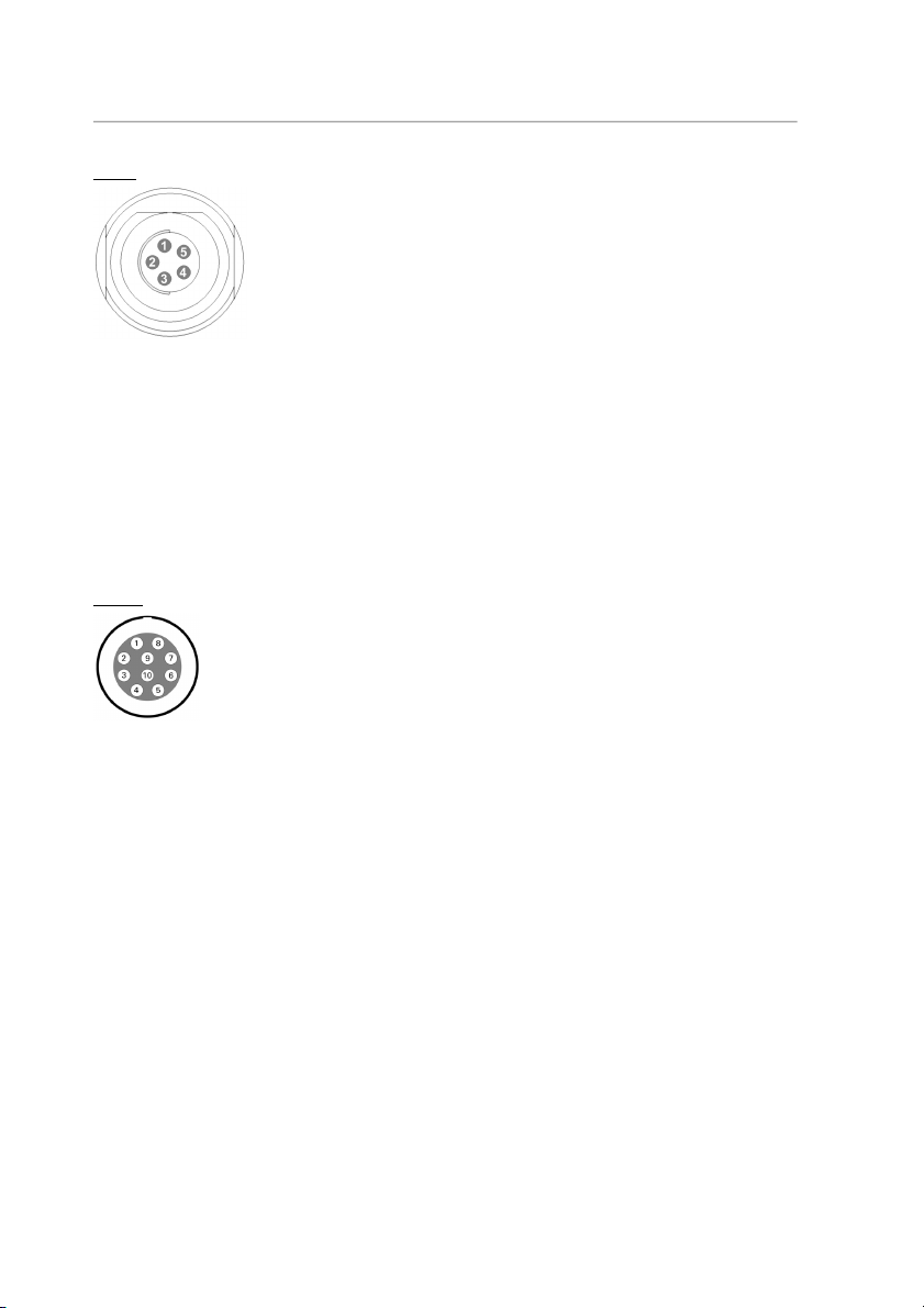
Connector Pin-Outs
CLM
1
GND
Ground
2
MTYPE-A
Motor type sense
3
MTYPE-B
Motor type sense
4
MTYPE-C
Motor type sense
5
+5V
Encoder supply
6
Encoder-A
Encoder input A
7
Encoder-B
Encoder input B
8
n.c.
9
n.c.
10
n.c.
11
Motor +
Motor drive output
12
Motor –
Motor drive output
Page 24
24 Single Motor Controller SMC-1 – User Manual
Version 09/2014
LCS
1
GND
Ground
2
n.c.
3
CAN-L
CAN bus
4
CAN-H
CAN bus
5
+V-BAT
Battery supply output
CAM
1
GND
Ground
2
+V-BAT
9.5 V to 34 V DC IN
3
RxD
RS232
4
TxD
RS232
5
R/S
ARRI R/S
6
RUN-SW2
Opto switch, connects to pin 8 @REC (max.
100 mA/50 V)
7
ACAM
Tally, analog input, active high (default value:
1.25 V transition level)
8
RUN-SW1
Opto switch, connects to pin 6 @REC (max.
100 mA/50 V)
9
DAC-CAM
REC, analog output, active high (default value
@REC: 3.3 V)
10
D-CAM
TALLY, digital input, active low, 3.3 V logic
signal level
Page 25
Single Motor Controller SMC-1 – User Manual 25
Version 09/2014
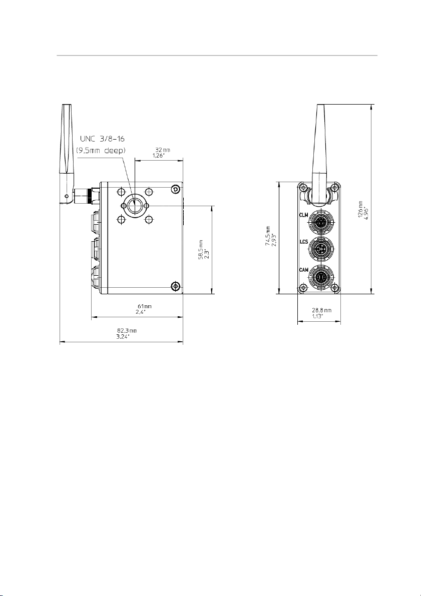
Dimensions and Weight
Weight (including antenna): 173 g
Page 26

26 Single Motor Controller SMC-1 – User Manual
Version 09/2014
Electrical Data
Supply Voltage: 9.5 V to 34 V DC (full motor speed)
Current Consumption: 100 mA@12 V (radio on/ready)
50 mA@24 V (radio on/ready)
Operating Temperature: -20 to +50 °C (-4 to +122 °F)
Radio System
The SMC-1 contains a radio unit that enables wireless lens control and
lens data communication with a white coded radio module. A white ring
at the base of the antenna mount point identifies it. It offers 8 channels
to choose from:
Channel Frequency
0 2.410 GHZ
1 2.415 GHZ
2 2.430 GHZ
3 2.435 GHZ
4 2.450 GHZ
5 2.455 GHZ
6 2.470 GHZ
7 2.475 GHZ
White radio and legacy yellow radio cannot be mixed in the same radio
network of camera and hand units. It is possible to use both systems in
parallel within different radio networks.
Page 27

Single Motor Controller SMC-1 – User Manual 27
Version 09/2014
ARRI Service Contacts
Munich, Germany
Arnold & Richter Cine Technik
+49 89 3809 2121
Business hours:
Mo. - Fr. 9:00 - 17:00 (CET)
London, Great Britain
ARRI CT Limited
+44 1895 457 051
Business hours:
Mo. - Thu. 9:00 - 17:30 (GMT)
Fr. 9:00 - 17:00 (GMT)
Milan, Italy
ARRI Italia S.r.l.
+39 (02)262 271 75
Business hours:
Mo. - Fr. 9:00 - 18:00 (CET)
Burbank, USA
ARRI Inc. West Coast
+1 877 565 2774
Business hours:
Mo. - Fr. 8:15 - 17:00 (PST)
New York, USA
ARRI Inc. East Coast
+1 877 565 2774
Business hours:
Mo. - Fr. 8:00 - 17:30 (EST)
Mississauga, Canada
ARRI Canada Limited
+1 416 255 3335
Business hours:
Mo. - Fr. 8:30 - 17:00 (EDT)
Hong Kong, China
ARRI Asia Limited
+852 2537 4266
Business hours:
Mo. - Fr. 10:00 - 18:30 (HKT)
Beijing, China
ARRI China Co. Limited
+86 10 5900 9680
Business hours:
Mo. - Fr. 9:00 - 18:00 (CST)
Page 28
28 Single Motor Controller SMC-1 – User Manual
Version 09/2014
Sydney, Australia
ARRI Australia Pty Ltd
+61 2 9855 4305
Business hours:
Mo. - Fr. 8:00 - 18:00 (AEST)
International Declarations and Certifications
EC Declaration of Conformity
The product Single Motor Controller SMC-1 conforms with the
specifications of the following European directives:
• Directive 2014/30/EU of the European Parliament and the
Council of 26 February 2014 on the harmonization of the laws of
the Member States relating to electromagnetic compatibility
• Directive 1999/5/EC of the European Parliament and the
Council of 9 March 1999 on radio equipment and
telecommunications terminal equipment and the mutual
recognition of their conformity
• Directive 2011/65/EU of the European Parliament and the
Council of 8 June 2011 on the restriction of the use of certain
hazardous substances in electrical and electronic equipment
The compliance with the requirements of the European Directives was
proved by the application of the following harmonized standards:
• EN 55022; EN 55103-1; EN 55103-2; EN 301 489-1; EN 301
489-17; EN 62479; EN 60950-1; DIN EN 50581
Page 29

Single Motor Controller SMC-1 – User Manual 29
Version 09/2014
FCC Class A Statement:
Note: This equipment has been tested and found to comply with the
limits for a Class A digital device, pursuant to Part 15 of the FCC Rules.
These limits are designed to provide reasonable protection against
harmful interference when the equipment is operated in a commercial
environment. This equipment generates, uses, and can radiate radio
frequency energy and, if not installed and used in accordance with the
instruction manual, may cause harmful interference to radio
communications. Operation of this equipment in a residential area is
likely to cause harmful interference in which case the user will be
required to correct the interference at his own expense.
Contains Transceiver module FCC-ID: Y7N-EMIP100
Industry Canada Compliance Statement
Complies with the Canadian ICES-003 Class A specifications.
Cet appareil numérique de la Classe A est conforme à la norme NMB003 du Canada.
This device complies with RSS 210 of Industry Canada. This Class A
device meets all the requirements of the Canadian interference-causing
equipment regulations.
Cet appareil numérique de la Classe A respecte toutes les exigences du
Réglement sur le matériel brouilleur du Canada.
Contains Transceiver Module IC-ID: 9482A-EMIP100
Page 30

30 Single Motor Controller SMC-1 – User Manual
Version 09/2014
Ident.-No.: K5.0003468 · Technical data subject to change without further notice. © ARRI/2014
Arnold & Richter Cine Techn ik GmbH & Co. Betriebs KG · Türkenstr. 89 · D-807 99 Munich · Phon e +49 (0)89 3809 0
 Loading...