

Page 1
SkyPanel
®
S30 / S60 / S120 / S360
C and RP Versions
U S E R M A N U A L
L5.0019845 / L03423
07 / 2019
Page 2

Revision History
Date Revision Changes Revisor
19-06-16 L03423
Added Light Engine Compensation Mode
Added Revision History
mfg
© 2019 Arnold & Richter Cine Technik GmbH & Co. Betriebs KG.
All rights reserved. Information subject to change without notice. ARRI and all affiliated companies disclaim liability for
any injury, damage, direct or indirect loss, consequential or economic loss or any other loss occasioned by the use of,
inability to use or reliance on the information contained in this document.
No part of this document may be used for distribution, reproduction, transmission, transcription, storage in a data retrieval system, or translated into any language in any form by any means without the prior written permission of ARRI®.
If you are downloading files from our web pages for your personal use, make sure to check for updated versions.
ARRI® cannot take any liability whatsoever for downloaded files, as technical data are subject to change without
notice.
Art-NetTM Designed by and Copyright Artistic Licence Holdings Ltd.
ARRI, ARRI ARRI, the ARRI Logo, ARRIMAX, ARRISUN, EB, L-Series, MAX Technology, M-Series, POCKETPAR,
True Blue, SkyPanel, SKYPANEL, T 12 and T 24 are registered trademarks of Arnold & Richter Cine Technik
GmbH & Co. Betriebs KG.
Page 3

Content
Introduction . . . . . . . . . . . . . . . . . . . . . . . . . . . . . . . . . . . . . . . . . . . . . . . . . . . . . . . . . . . . . . . . . . . . . . . . . .5
Features . . . . . . . . . . . . . . . . . . . . . . . . . . . . . . . . . . . . . . . . . . . . . . . . . . . . . . . . . . . . . . . . . . . . . . . . . . .5
Properties . . . . . . . . . . . . . . . . . . . . . . . . . . . . . . . . . . . . . . . . . . . . . . . . . . . . . . . . . . . . . . . . . . . . . . . . . .5
Fixture Menu . . . . . . . . . . . . . . . . . . . . . . . . . . . . . . . . . . . . . . . . . . . . . . . . . . . . . . . . . . . . . . . . . . . . . . . . . .7
Overview . . . . . . . . . . . . . . . . . . . . . . . . . . . . . . . . . . . . . . . . . . . . . . . . . . . . . . . . . . . . . . . . . . . . . . . . . . . 7
Features of the Fixture Menu . . . . . . . . . . . . . . . . . . . . . . . . . . . . . . . . . . . . . . . . . . . . . . . . . . . . . . . . . . .7
POWER-LED (1) . . . . . . . . . . . . . . . . . . . . . . . . . . . . . . . . . . . . . . . . . . . . . . . . . . . . . . . . . . . . . . . . . .7
DATA-LED (2) . . . . . . . . . . . . . . . . . . . . . . . . . . . . . . . . . . . . . . . . . . . . . . . . . . . . . . . . . . . . . . . . . . . .7
STATUS-LED (3) . . . . . . . . . . . . . . . . . . . . . . . . . . . . . . . . . . . . . . . . . . . . . . . . . . . . . . . . . . . . . . . . . .8
INTENSITY/SELECTOR (I/S, 4) . . . . . . . . . . . . . . . . . . . . . . . . . . . . . . . . . . . . . . . . . . . . . . . . . . . . . .8
Central Rotary Knob (5) . . . . . . . . . . . . . . . . . . . . . . . . . . . . . . . . . . . . . . . . . . . . . . . . . . . . . . . . . . . . .8
Right Rotary Knob (6) . . . . . . . . . . . . . . . . . . . . . . . . . . . . . . . . . . . . . . . . . . . . . . . . . . . . . . . . . . . . . .8
PRESET (7) . . . . . . . . . . . . . . . . . . . . . . . . . . . . . . . . . . . . . . . . . . . . . . . . . . . . . . . . . . . . . . . . . . . . . .8
MODE (8) . . . . . . . . . . . . . . . . . . . . . . . . . . . . . . . . . . . . . . . . . . . . . . . . . . . . . . . . . . . . . . . . . . . . . . . .8
DISPLAY (9) . . . . . . . . . . . . . . . . . . . . . . . . . . . . . . . . . . . . . . . . . . . . . . . . . . . . . . . . . . . . . . . . . . . . . 8
MENU (10) . . . . . . . . . . . . . . . . . . . . . . . . . . . . . . . . . . . . . . . . . . . . . . . . . . . . . . . . . . . . . . . . . . . . . . .9
BACK (11) . . . . . . . . . . . . . . . . . . . . . . . . . . . . . . . . . . . . . . . . . . . . . . . . . . . . . . . . . . . . . . . . . . . . . . .9
To lock the fixture menu . . . . . . . . . . . . . . . . . . . . . . . . . . . . . . . . . . . . . . . . . . . . . . . . . . . . . . . . . . . . . 9
To Set the Operation Mode . . . . . . . . . . . . . . . . . . . . . . . . . . . . . . . . . . . . . . . . . . . . . . . . . . . . . . . . . . . . .9
SkyPanel Remote . . . . . . . . . . . . . . . . . . . . . . . . . . . . . . . . . . . . . . . . . . . . . . . . . . . . . . . . . . . . . . . . . . . .9
ContentContent
Fixture Modes . . . . . . . . . . . . . . . . . . . . . . . . . . . . . . . . . . . . . . . . . . . . . . . . . . . . . . . . . . . . . . . . . . . . . . . .10
CCT and RGBW . . . . . . . . . . . . . . . . . . . . . . . . . . . . . . . . . . . . . . . . . . . . . . . . . . . . . . . . . . . . . . . . . 10
CCT . . . . . . . . . . . . . . . . . . . . . . . . . . . . . . . . . . . . . . . . . . . . . . . . . . . . . . . . . . . . . . . . . . . . . . . . . . . 10
CCT & HSI . . . . . . . . . . . . . . . . . . . . . . . . . . . . . . . . . . . . . . . . . . . . . . . . . . . . . . . . . . . . . . . . . . . . . .10
RGBW . . . . . . . . . . . . . . . . . . . . . . . . . . . . . . . . . . . . . . . . . . . . . . . . . . . . . . . . . . . . . . . . . . . . . . . . .10
HSI . . . . . . . . . . . . . . . . . . . . . . . . . . . . . . . . . . . . . . . . . . . . . . . . . . . . . . . . . . . . . . . . . . . . . . . . . . . .10
GEL . . . . . . . . . . . . . . . . . . . . . . . . . . . . . . . . . . . . . . . . . . . . . . . . . . . . . . . . . . . . . . . . . . . . . . . . . . .10
xy Coordinates . . . . . . . . . . . . . . . . . . . . . . . . . . . . . . . . . . . . . . . . . . . . . . . . . . . . . . . . . . . . . . . . . . .10
Source Matching . . . . . . . . . . . . . . . . . . . . . . . . . . . . . . . . . . . . . . . . . . . . . . . . . . . . . . . . . . . . . . . . .10
Light Effects . . . . . . . . . . . . . . . . . . . . . . . . . . . . . . . . . . . . . . . . . . . . . . . . . . . . . . . . . . . . . . . . . . . . .11
Light Engine Control via DMX . . . . . . . . . . . . . . . . . . . . . . . . . . . . . . . . . . . . . . . . . . . . . . . . . . . . . . .11
Ultimate DMX Mode . . . . . . . . . . . . . . . . . . . . . . . . . . . . . . . . . . . . . . . . . . . . . . . . . . . . . . . . . . . . . . .11
Extended color control . . . . . . . . . . . . . . . . . . . . . . . . . . . . . . . . . . . . . . . . . . . . . . . . . . . . . . . . . . . . .11
User Guide for SkyPanel as Decorative Lights . . . . . . . . . . . . . . . . . . . . . . . . . . . . . . . . . . . . . . . . . .11
Functions . . . . . . . . . . . . . . . . . . . . . . . . . . . . . . . . . . . . . . . . . . . . . . . . . . . . . . . . . . . . . . . . . . . . . . . . . . .12
To set the Lighting Parameters in CCT Mode . . . . . . . . . . . . . . . . . . . . . . . . . . . . . . . . . . . . . . . . . . . . . .12
To set the Color in HSI Mode . . . . . . . . . . . . . . . . . . . . . . . . . . . . . . . . . . . . . . . . . . . . . . . . . . . . . . . . . .12
To set the Lighting Parameters in GEL Mode . . . . . . . . . . . . . . . . . . . . . . . . . . . . . . . . . . . . . . . . . . . . . .12
To set the Light Source in Source Mode . . . . . . . . . . . . . . . . . . . . . . . . . . . . . . . . . . . . . . . . . . . . . . . . . .12
To set the Color in RGBW Mode . . . . . . . . . . . . . . . . . . . . . . . . . . . . . . . . . . . . . . . . . . . . . . . . . . . . . . . .12
To set the Color in X,Y Mode . . . . . . . . . . . . . . . . . . . . . . . . . . . . . . . . . . . . . . . . . . . . . . . . . . . . . . . . . .12
Extended Color Control . . . . . . . . . . . . . . . . . . . . . . . . . . . . . . . . . . . . . . . . . . . . . . . . . . . . . . . . . . . . . . .12
To Use the Extended Color Control via DMX . . . . . . . . . . . . . . . . . . . . . . . . . . . . . . . . . . . . . . . . . . .13
To Use the Extended Color Control via the Control Panel . . . . . . . . . . . . . . . . . . . . . . . . . . . . . . . . . . 13
To Set the Brightness in all Operating Modes . . . . . . . . . . . . . . . . . . . . . . . . . . . . . . . . . . . . . . . . . . . . . .14
To Set the Dimming Curve . . . . . . . . . . . . . . . . . . . . . . . . . . . . . . . . . . . . . . . . . . . . . . . . . . . . . . . . . . . .14
To Set a Special Control Mode . . . . . . . . . . . . . . . . . . . . . . . . . . . . . . . . . . . . . . . . . . . . . . . . . . . . . . . . . 14
Stage Mode . . . . . . . . . . . . . . . . . . . . . . . . . . . . . . . . . . . . . . . . . . . . . . . . . . . . . . . . . . . . . . . . . . . . . 14
3
3
Page 4

Content
Master/Slave Mode . . . . . . . . . . . . . . . . . . . . . . . . . . . . . . . . . . . . . . . . . . . . . . . . . . . . . . . . . . . . . . . . . . 16
Calibrated RGBW Color Space . . . . . . . . . . . . . . . . . . . . . . . . . . . . . . . . . . . . . . . . . . . . . . . . . . . . . . . . .16
Frequency Selection . . . . . . . . . . . . . . . . . . . . . . . . . . . . . . . . . . . . . . . . . . . . . . . . . . . . . . . . . . . . . . . . .16
To set the Fan Mode . . . . . . . . . . . . . . . . . . . . . . . . . . . . . . . . . . . . . . . . . . . . . . . . . . . . . . . . . . . . . . . . .17
Lighting Effects . . . . . . . . . . . . . . . . . . . . . . . . . . . . . . . . . . . . . . . . . . . . . . . . . . . . . . . . . . . . . . . . . . . . .17
To Activate and set Effect Parameters with the Fixture Menu . . . . . . . . . . . . . . . . . . . . . . . . . . . . . . . . . 20
To Set the Display Behavior . . . . . . . . . . . . . . . . . . . . . . . . . . . . . . . . . . . . . . . . . . . . . . . . . . . . . . . . . . .22
USB Functions . . . . . . . . . . . . . . . . . . . . . . . . . . . . . . . . . . . . . . . . . . . . . . . . . . . . . . . . . . . . . . . . . . . . . 22
Preset Lists . . . . . . . . . . . . . . . . . . . . . . . . . . . . . . . . . . . . . . . . . . . . . . . . . . . . . . . . . . . . . . . . . . . . . . . .22
To Save and Load Fixture Settings . . . . . . . . . . . . . . . . . . . . . . . . . . . . . . . . . . . . . . . . . . . . . . . . . . . . . . 23
To Save the Error and Service Log . . . . . . . . . . . . . . . . . . . . . . . . . . . . . . . . . . . . . . . . . . . . . . . . . . . . . .24
To Read out Fixture Settings . . . . . . . . . . . . . . . . . . . . . . . . . . . . . . . . . . . . . . . . . . . . . . . . . . . . . . . . . .24
To Read out Fixture Information . . . . . . . . . . . . . . . . . . . . . . . . . . . . . . . . . . . . . . . . . . . . . . . . . . . . . . . .24
To Perform a Factory Reset . . . . . . . . . . . . . . . . . . . . . . . . . . . . . . . . . . . . . . . . . . . . . . . . . . . . . . . . . . .24
Light Engine Compensation (C-Versions only) . . . . . . . . . . . . . . . . . . . . . . . . . . . . . . . . . . . . . . . . . . . . . 24
Low End Mode . . . . . . . . . . . . . . . . . . . . . . . . . . . . . . . . . . . . . . . . . . . . . . . . . . . . . . . . . . . . . . . . . . .15
Tungsten Mode . . . . . . . . . . . . . . . . . . . . . . . . . . . . . . . . . . . . . . . . . . . . . . . . . . . . . . . . . . . . . . . . . .15
High Speed Mode . . . . . . . . . . . . . . . . . . . . . . . . . . . . . . . . . . . . . . . . . . . . . . . . . . . . . . . . . . . . . . . .15
Overview of the Special Control Modes . . . . . . . . . . . . . . . . . . . . . . . . . . . . . . . . . . . . . . . . . . . . . . . .15
DMX . . . . . . . . . . . . . . . . . . . . . . . . . . . . . . . . . . . . . . . . . . . . . . . . . . . . . . . . . . . . . . . . . . . . . . . . . . . . . . . .26
Priorities . . . . . . . . . . . . . . . . . . . . . . . . . . . . . . . . . . . . . . . . . . . . . . . . . . . . . . . . . . . . . . . . . . . . . . . . . . 26
DMX Address . . . . . . . . . . . . . . . . . . . . . . . . . . . . . . . . . . . . . . . . . . . . . . . . . . . . . . . . . . . . . . . . . . . . . .26
DMX Mode . . . . . . . . . . . . . . . . . . . . . . . . . . . . . . . . . . . . . . . . . . . . . . . . . . . . . . . . . . . . . . . . . . . . . . . . 26
DMX-Signal-Loss Behavior . . . . . . . . . . . . . . . . . . . . . . . . . . . . . . . . . . . . . . . . . . . . . . . . . . . . . . . . . . . .26
Wireless DMX . . . . . . . . . . . . . . . . . . . . . . . . . . . . . . . . . . . . . . . . . . . . . . . . . . . . . . . . . . . . . . . . . . . . . .27
Networking . . . . . . . . . . . . . . . . . . . . . . . . . . . . . . . . . . . . . . . . . . . . . . . . . . . . . . . . . . . . . . . . . . . . . . . . . . 28
Art-Net and sACN 28 . . . . . . . . . . . . . . . . . . . . . . . . . . . . . . . . . . . . . . . . . . . . . . . . . . . . . . . . . . . . . . . . .28
Art-Net IP Address . . . . . . . . . . . . . . . . . . . . . . . . . . . . . . . . . . . . . . . . . . . . . . . . . . . . . . . . . . . . . . . .28
Art-Net Net . . . . . . . . . . . . . . . . . . . . . . . . . . . . . . . . . . . . . . . . . . . . . . . . . . . . . . . . . . . . . . . . . . . . . .28
Sub-Net . . . . . . . . . . . . . . . . . . . . . . . . . . . . . . . . . . . . . . . . . . . . . . . . . . . . . . . . . . . . . . . . . . . . . . . .28
Universe . . . . . . . . . . . . . . . . . . . . . . . . . . . . . . . . . . . . . . . . . . . . . . . . . . . . . . . . . . . . . . . . . . . . . . . .28
Art-Net Merge Mode . . . . . . . . . . . . . . . . . . . . . . . . . . . . . . . . . . . . . . . . . . . . . . . . . . . . . . . . . . . . . . 28
Art-Net Gateway . . . . . . . . . . . . . . . . . . . . . . . . . . . . . . . . . . . . . . . . . . . . . . . . . . . . . . . . . . . . . . . . . 28
Network Settings . . . . . . . . . . . . . . . . . . . . . . . . . . . . . . . . . . . . . . . . . . . . . . . . . . . . . . . . . . . . . . . . . . . .29
ARRI Lighting Service Manager . . . . . . . . . . . . . . . . . . . . . . . . . . . . . . . . . . . . . . . . . . . . . . . . . . . . . . . .29
SkyPanel Web Portal . . . . . . . . . . . . . . . . . . . . . . . . . . . . . . . . . . . . . . . . . . . . . . . . . . . . . . . . . . . . . . . . 30
Overview of the Fixture Menu . . . . . . . . . . . . . . . . . . . . . . . . . . . . . . . . . . . . . . . . . . . . . . . . . . . . . . . . . . .31
RDM Commands . . . . . . . . . . . . . . . . . . . . . . . . . . . . . . . . . . . . . . . . . . . . . . . . . . . . . . . . . . . . . . . . . . . . . 35
Error Codes . . . . . . . . . . . . . . . . . . . . . . . . . . . . . . . . . . . . . . . . . . . . . . . . . . . . . . . . . . . . . . . . . . . . . . . . . 36
Overview of Typical CCT Values as DMX Values . . . . . . . . . . . . . . . . . . . . . . . . . . . . . . . . . . . . . . . . . . . .37
4
Page 5
Introduction
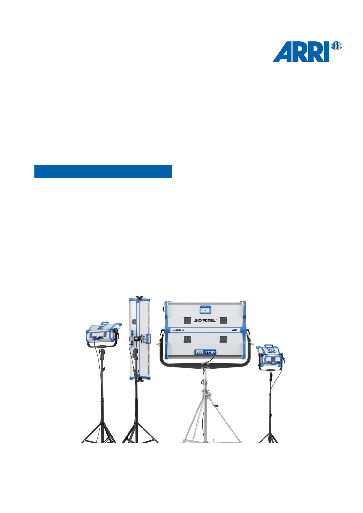
Thank you for selecting a SkyPanel LED soft light from ARRI. The SkyPanel is a compact, ultra-bright and
high-quality LED soft light. It is much more efficient than a soft light with a conventional light source.
The different models of the SkyPanel emit white light with a fixed color temperature or colored light with
adjustable color temperature and adjustable green-magenta point. The light spectrum is optimized for excellent color rendition and fulfills perfect the demands of modern, digital cameras. All models of the SkyPanel can be controlled using the common DMX512-A protocol, Art-Net, sACN or the fixture menu.
Please observe the SkyPanel Installation and Safety Manual. The manual is available for free download on
the ARRI web site www.arri.com.
This manual describes the C and RP models of the SkyPanel. Please note, that the RP model emits
only white light with a fixed color temperature. The color temperature is defined by the Phosphor
panel used.
Features
Light Field
IntroductionIntroduction
NOTICE
The SkyPanel offers the same functionality as a conventional soft light.
Even Light Field
The SkyPanel soft light produces a homogeneous, single-shadow light field, delivering natural results.
Vibrant Colors, Full Spectrum Lighting
True-to-life color rendition is an outstanding feature of the SkyPanel. The fully tunable white light of the
SkyPanel can be adjusted for different skin tones, camera sensors and mixed light environments. Full gamut color mixing enables the rendition of all color shades. The extensive gel library (from firmware version
2.0) offers a wide range of familiar colors at the user’s fingertips.
Cool Light Beam
The SkyPanel does not emit any infrared or UV radiation and thus does not forward heat, making actors
feel comfortable in the light beam.
Properties
Accessory Holder
Diffuser plates or an intensifier is placed on the front of the fixture and secured by locking guiding rails or
held by four locking pins. Both the diffuser and intensifier of the S360-C are equipped with guiding rails at
the front to carry other accessories for shaping the light like a honey comb.
Yoke
The aluminum or carbon fiber yoke provides high strength with minimum weight. The short metal yoke (only
S360-C) is the perfect solution when the SkyPanel is mounted in a grid facing downwards.
5
5
Page 6
Tilt-Lock
The high strength tilt-locks on each side of the stirrup provide secure locking. It eliminates movement and
slippage and ensures that the SkyPanel will stay where you put it.
Introduction
Control
All functions of the SkyPanel are controllable through DMX, Art-Net or sACN. The SkyPanel is also fully
RDM compatible (via DMX and Art-Net with suitable controllers) and is equipped with an RDM feedback
channel for reporting all set parameters including system status.
The SkyPanel S360-C is equipped with an integrated CRMX transceiver for wireless control and RDM communication. All other models of the SkyPanel series can be controlled wireless when using the SkyLink
system, which is available as an accessory.
Fixture Menu
For location applications the SkyPanel is equipped with a fixture menu for manual adjustment of intensity,
color temperature, green-magenta point as well as hue and saturation and other parameters.
Control Options
You can set up or control the SkyPanel with the options listed in the table below
Option Control Configuration Information
Fixture menu Yes Yes page 6
Please see „DMX
DMX Yes No
CRMX
(wireless DMX)*
RDM No Yes page 35
Art-Net and sACN Yes No page 11
ALSM No Yes page 29
Web Portal No Yes page 30
Stellar App Yes No www.arri.com/stellar/
Yes No page 27
protocol specification (free download
from www.arri.com)
The model S360-C is equipped with an internal CRMX Transceiver, all other models need to be connected
to the SkyLink system (accessory) to gain wireless control.
6
Page 7
Fixture Menu
This section describes the fixture menu of the SkyPanel and the SkyPanel remote control. Some options, especially
options for saving and loading data, are not available in the remote control fixture menu.
Overview
11
10
Fixture MenuFixture Menu
9
1
2
3
4
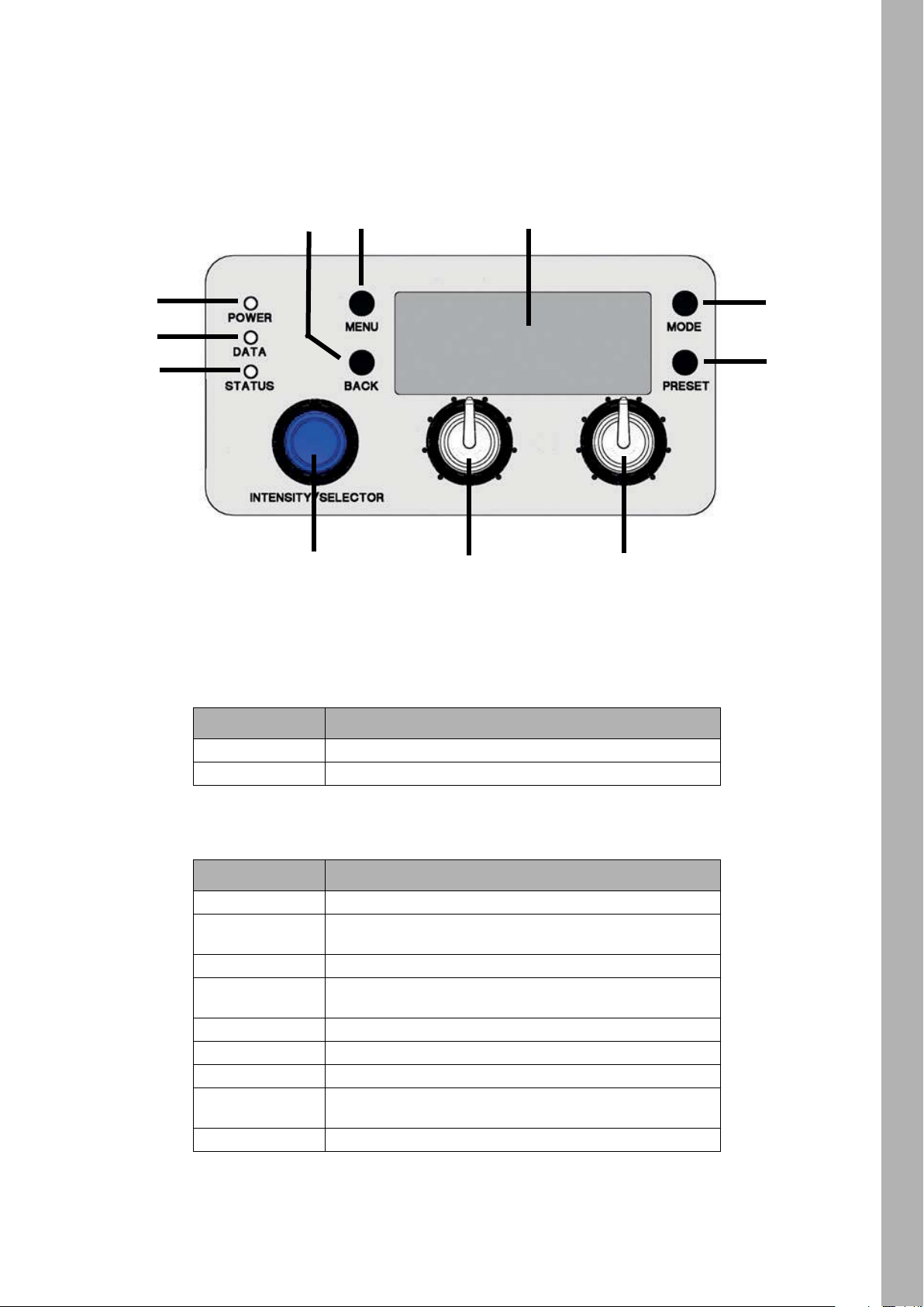
Features of the Fixture Menu
POWER-LED (1)
Color Indication
Green Fixture switched on. No error.
No color Fixture switched off.
8
7
5
6
DATA-LED (2)
Color Indication
Blue The fixture receives a valid DMX signal.
Blue / green
Purple Master mode active
White
Green Receiving valid Art-Net signal, Gateway not active
Orange Receiving valid sACN signal, Gateway active
Cyan Receiving valid sACN signal, Gateway not active
Red
No light The fixture receives no valid control signal.
The fixture receives a valid CRMX (wireless DMX) signal
(only S360-C).
Receiving valid Art-Net signal or communicating via RDM,
Gateway active
No communication between fixture menu and controller
board.
7
7
Page 8
Fixture Menu
STATUS-LED (3)
Color Indication
Green No error. Normal temperature.
Red flashing (0,5s rhythm)*
*
Red
Change from red to green
Red flashing (0,25s Rhythm)
*Display lights up red when STATUS-LED is lit red
*
*
Warning fixture over temperature (only
with fan modes LOW and High Speed).
Fixture over temperature.
Fixture normal temperature.
Calibration data not loaded.
INTENSITY/SELECTOR (I/S, 4)
The INTENSITY/SELECTOR encoder I/S has two functions:
• Fixture menu closed: Setting the intensity.
• Fixture menu open: Use I/S to scroll through the menu, open sub menus and set parameters. Pressing
the knob opens sub menus and confirms settings.
Central Rotary Knob (5)
Use the rotary knob to set the color temperature (CCT) or the color hue (HUE). The current function of the
rotary knob is shown in the display (9) above the knob.
Right Rotary Knob (6)
Use the rotary knob to set the green- magenta point or the color saturation (SAT) or, dependent on the active color mode, categories or parameters. The current function of the rotary knob is shown in the display
(9) above the knob.
PRESET (7)
To call up a preset
A short press of the PRESET button brings up the list of all available presets. Turn I/S (4) to select one of
10 factory presets and 10 user definable presets. Press I/S (4) to activate the preset.
To store a preset
Use the fixture menu to adjust the settings. Hold PRESET, until the preset save dialog opens. Turn I/S (4)
to select a preset memory slot. Press I/S (4) to store the preset. Close the dialog with BACK.
MODE (8)
Press the MODE button short to swap between CCT, HSI, GEL, Source Matching, RGBW mode and X,Y
mode of the SkyPanel.
Press the MODE button long (> 3 sec.) to activate the extended color control. The extended color control
feature is not available in RGBW mode unless RGBW Calibrated Color Space is activated.
DISPLAY (9)
The display shows the current settings and other information during normal operation. Press the MENU
button (4) to open or close the fixture menu. Use I/S (4) and the BACK button (11) to navigate through the
fixture menu.
8
Page 9

MENU (10)
The MENU button opens the fixture menu. Press MENU when the fixture menu is open to close the menu
and abort an action (Escape). Use I/S (4) to scroll through the menu, open sub menus and set parameters.
Press MENU long to display the menus which are used most.
BACK (11)
The BACK button closes a sub menu and aborts an action (Escape). Compared to the MENU button (10)
the BACK button only closes the sub menu, but not the fixture menu.
Press BACK long to display the last used menus.
To lock the fixture menu
• Press I/S in the home screen for 5 seconds to lock all buttons and knobs. Use the feature to prevent an
accidental change of settings.
• The word „LOCKED“ appears on the display when locked.
• Press I/S in the home screen for 5 seconds again to unlock all buttons and knobs.
• Please find a overview in chapter “Overview of the Fixture Menu” on page 31.
To Set the Operation Mode
Fixture MenuFixture Menu
Press the MODE button (8) short to switch from CCT to HSI to GEL to Source to RGBW to X,Y and back
to CCT mode.
In CCT mode the SkyPanel generates white light with optimized color rendition. In HSI mode the SkyPanel
generates colored light. If saturation is set very low, the SkyPanel generates white light, but not with optimized color rendition. The GEL mode offers an extensive color gel library. In Source mode the SkyPanel
generates the light of traditional light sources. Use the RGBW mode to generate a RGBW color using the
control panel. The X,Y mode generates a color defined by its X,Y coordinates.
Press the MODE button long (> 3 sec.) to activate the extended color control. The extended color control
feature is not available in RGBW mode unless RGBW Calibrated Color Space is activated.
SkyPanel Remote
The SkyPanel Remote is connected with an USB cable to a SkyPanel softlight. It is powered by the
SkyPanel and does not use a battery. The SkyPanel Remote emulates the SkyPanel fixture menu. Each
SkyPanel Remote controls one SkyPanel.
Use multiple SkyPanel softlights in a master / slave configuation to control them with one SkyPanel
Remote.
The SkyPanel checks the firmware of the SkyPanel Remote every time it is connected. If the firmware version of the SkyPanel Remote is different to the firmware version of the SkyPanel the SkyPanel Remote
firmware will be synchronized automatically, no matter if it is an up- or downgrade.
9
9
Page 10

Fixture Modes
The SkyPanel offers, depending on the model, up to 31 control modes. Use the 8 bit modes with basic controllers like dimmer consoles.
Fixture Modes
ARRI recommends the use of the 16 bit modes in combination with controllers supporting 16 bit resolution
to obtain best results. The high resolution provides smooth dimming and precise color adjustments.
The coarse / fine modes utilize two channels for most parameters and provide higher resolution compared
to the 8 bit modes in combination with controllers that do not support true 16 bit resolution. One channel
sets the coarse value between 0 and 255 of the function. Each step is divided in 256 increments using the
fine channel. This way it is possible to control the light very precise without using a true 16 bit resolution.
Below is a short overview of the different control modes. Please find a detailed overview of all DMX modes
in the document „SkyPanel DMX Protocol Specification“ which is available for free download on the ARRI
website www.arri.com.
CCT and RGBW
This mode provides control of intensity, color temperature, green-magenta point and individual channels
for controlling the red, green, blue and white color (only SkyPanel-C).
CCT
Simple white-only mode. It is used when the number of available channels of the controller is very limited.
It provides control of intensity, color temperature and green-magenta point.
CCT & HSI
Provides control of intensity, color temperature, green-magenta point, hue and saturation (HSI = hue, saturation, intensity). In HSI mode (only SkyPanel-C) the color and intensity is very even over the fixtures as
it is controlled using color algorithms which take the tolerances of the light engines into account during calculation.
RGBW
Simple mode for controlling the overall intensity and the red, green, blue and white intensity when only a
limited number of channels is available. Please find more information about the RGB color space on
page 16.
HSI
Simple mode for controlling hue, saturation and intensity when a limited number of channels is available.
GEL
The GEL mode offers an extensive color filter list. The color temperature has two settings, 3.200 K and
5.600 K. The intensity can be controlled as usual.
10
xy Coordinates
The xy mode determines the color displayed by its xy coordinates in the CIE 1931 diagram. Set the x and
y coordinate with 8 bit or 16 bit resolution. One channel determines the transition type when fading from
one color to another color.
Source Matching
Select from a list of light sources to match that color and spectrum. Source Matching saves a lot of time
when you need a specific illumination. Select from 50 different light sources the one which fits best to your
demands.
Page 11
Light Effects
The SkyPanel contains a light effect engine with 13 different light effects. Activating a light effect is very
easy. Just activate a light effect via the fixture menu, DMX, Art-Net or sACN and set the parameters to get
exactly the effect you need.
Light Engine Control via DMX
The light engines of the SkyPanel can be controlled individually. The control modes CCT & RGBW, HSI
and X,Y coordinates apply to all light engines of a fixture, but you can set the corresponding parameters of
each light engine individually. The S30 has one light engine, the S60 has two, the S120 has four, and the
S360 has twelve light engines.
Ultimate DMX Mode
The ultimate DMX mode allows the combination of different control modes. You can select two modes and
fade between them. This allows you to quickly select, prepare and crossfade the most suitable control
modes for your application.
Extended color control
The extended color control allows to intuitively modify the current color. If extended color control is active,
eight parameters are added to each control mode (see “Extended Color Control” on page 12).
NOTICE
Depending on the selected mode the channels required for each SkyPanel should be allocated in
the controller to provide independent control of all SkyPanels connected to the controller.
Fixture ModesFixture Modes
User Guide for SkyPanel as Decorative Lights
ARRI lighting products are being applied into an increasing amount of application scenarios.
When used as a decorative light in events, exhibition or live shows, SkyPanels can perform for the eyes of
the audience as well as for the camera by using the recommend settings below:
• Use a calibrated color mode such as HSI or CCT mode. RGBW mode can also be used if
"RGBW Calibrated Color“ is turned on.
• In case low intensity output is needed, ARRI recommends to activate Low End Mode.
• Intensity levels above 1% will yield better results. This applies to all above mentioned modes and all
dimming curves
11
11
Page 12
Functions
Functions
To set the Lighting Parameters in CCT Mode
Set the color temperature continuously with the central rotary knob (5). Set the Green-Magenta point
continuously with the right rotary knob (6). The current setting is displayed above the rotary knobs.
To set the Color in HSI Mode
Set the hue continuously with the central rotary knob (5). Set the saturation continuously with the right
rotary knob (6). The current setting is displayed above the rotary knobs.
To set the Lighting Parameters in GEL Mode
Use the central rotary knob (5) to set the color temperature 3.200 K or 5.600 K. The right rotary knob (6)
offers two options: „Best color“ displays the gel with optimized color quality, „Brightest“ displays the gel with
optimized brightness.
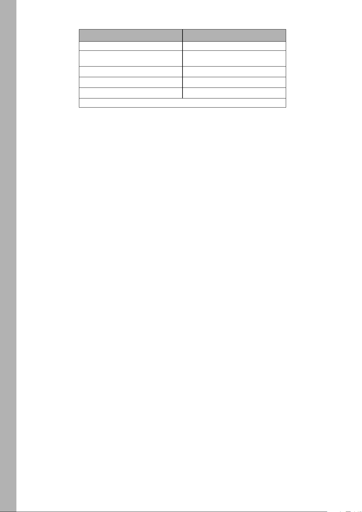
• Press I/S (4) to open the gel library. Choose the gel manufacturer (Rosco or LEE) with the central rotary
knob (5). Use the right rotary knob (6) to activate a gel category as shown in the table below.
Rosco LEE
Color Correction Color Correction
CalColor Color Filters
Storaro Selection 600 Series
Cinelux Cosmetic
700 Series
• Turn I/S (4) to call up a gel from the gel set. Press I/S to select a gel or press BACK (11) to close the gel
set and set the intensity with I/S (4). Press I/S (4) again, to re-open the gel set.
To set the Light Source in Source Mode
Activate the source mode and press I/S to call up a list of the light sources available. Use the right rotary
knob (6) to select the category (please see „DMX protocol specification“, which is available for free download for a detailed list). Turn I/S to select a light source. The SkyPanel calls up the selected light source in
real time. Press I/S to choose the selected light source.
To set the Color in RGBW Mode
The central rotary knob (5) has no function in RGBW mode. Use the right rotary knob (6) to select the functionality of the encoder I/S (4). Dependent on the selection of the right rotary knob, I/S is used to set the
overall intensity of the red, green, blue and white color. Please note the setting „Direct Control“ or
„RGBW Color Space (see page 16). You can store the RGBW color as a preset.
To set the Color in X,Y Mode
The X,Y mode defines the color using its x,y coordinates. use the right rotary knob (6) to select the
functionality of the encoder I/S (4). Dependent on the selection of the right rotary knob, I/S is used to set
the intensity, the X or Y coordinate of the color. The range of both the X and Y coordinate is 0.0000 to
0.8000.
12
Extended Color Control
The extended color control allows the modification of the selected color in an intuitive way. It can be used
both via the control panel or DMX.
Page 13

To Use the Extended Color Control via DMX
The SkyPanel applies 8 additional channels to every DMX mode when the extended color control is activated vie the DMX settings menu. Please find more information in the „SkyPanel DMX Protocol Specification“ which is available for free download on the ARRI web site www.arri.com.
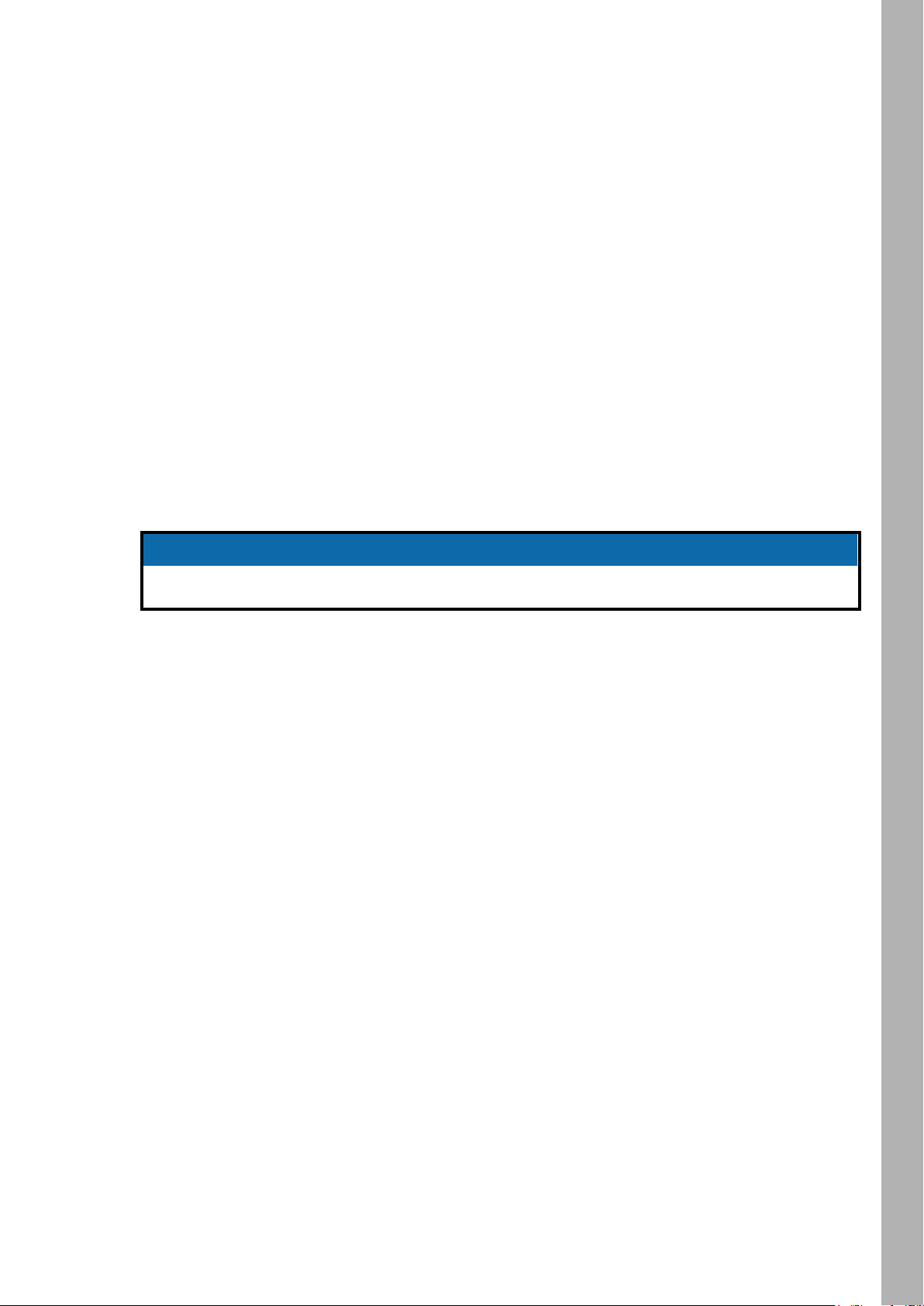
NOTICE
The extended color control is not available in LE DMX control modes.
To Use the Extended Color Control via the Control Panel
Press the MODE button for approximately 3 sec in the home screen to activate the extended color control.
If RGBW direct mode is active, the extended color control is not available. Please activate the calibrated
RGBW color mode ( see “Calibrated RGBW Color Space” on page 16) to be able to activate the extended
color control. If the extended color control is active, a short press of the MODE button switches between
the operation modes (see“To Set the Operation Mode” on page 9
If an effect is active, press the MODE button for at least 3 sec to switch between the color mode, the extended color control screen and the effect parameter screen.
The picture below shows the color control screen.
FunctionsFunctions
In the upper left and right corner of the display the active special and operation modes are displayed similar
to the home screen (in the picture above „HSI“ operation mode).
Each parameter available is shown as a slider. Neutral parameters are indicated with the solid horizontal
line at the middle of the bar. The horizontal bar of each slider indicates the value of each parameter. The
selected parameter is indicated by a small bar under its slider. The name of the parameter and its value is
shown under the sliders in the display.
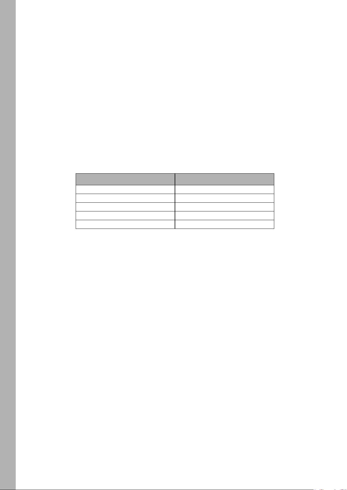
From left to right, the bars in the extended color control screen stand for the following parameters:.
Description Parameter Range
Color temperature Warmer / Cooler
Saturation Saturate / Desaturate
Red portion of current color + Red / - Red
Green portion of current color + Green / - Green
Blue portion of current color + Blue / - Blue
Cyan portion of current color + Cyan / - Cyan
Magenta portion of current color + Magenta / - Magenta
Yellow portion of current color + Yellow / - Yellow
Select the parameter using the right rotary knob (6). Set the value of the parameter with the encoder I/S
(4). Please note:
• The resolution of the encoder adapts dynamically to the moving speed.
• Clockwise turn increments the value of the parameter.
• Counter-clockwise turn decrements the value of the parameter.
• Double press within 800 ms resets the selected parameter to neutral (0).
• Triple press within 1200 ms resets all parameters to neutral (0).
When changing the operation mode the current values of the parameters are stored and restored when
activating the operation mode the next time. After a power cycle, the SkyPanel extended color control parameters are restored for each operation mode.
-1.000 > 0.000 > +1.000
13
13
Page 14

With activated extended color control:
• A star next to the active operation mode indicates the activated extended color control,
• the parameters are stored with each preset. Presets which contain parameters of the extended color con-
Functions
trol are marked with a star,
• modifying an extended color control parameters leaves any active preset,
• the calibrated RGBW color space is activated by the SkyPanel when the extended color control is activated via DMX,
• the direct RGBW color space is not available,
• the parameters are applied both to the start and end point of a cross fading,
• the parameters are not applied to lighting effects.
Presets made in Firmware 4.0 or higher will not work on lower firmware versions.
To Set the Brightness in all Operating Modes
Set the brightness in both operating modes continuously with the encoder I/S (4). The setting is dynamic:
Turning the encoder fast changes the intensity in coarse steps, turning it slow changes the intensity in fine
steps.
NOTE
To Set the Dimming Curve
The SkyPanel supports four dimming curves. The dimming curves are global: They affect both the intensity
control via the fixture menu or DMX, wireless DMX, Art-Net and sACN.
• Linear: The intensity changes proportional to the encoder I/S (4) or the channel value.
• Exponential: The resolution is high at lower intensity levels and low at higher intensity levels. Use this
dimming curve when you need a high resolution at low intensity levels. This is the default setting.
• Logarithmic: The resolution is low at lower intensity levels and high at higher intensity levels. Use this
dimming curve when you need a high resolution at high intensity levels.
• „S“ curve: The resolution is both high at lower and higher intensity levels and low at intensity levels in
between. Use this dimming curve, when you need a high resolution at low and high intensity levels.
To set the dimming curve
1.Press the MENU button (10) to open the fixture menu.
2.Turn I/S, until „Light Control“ is selected. Press I/S to open the menu.
3.Turn I/S, until „Dimming Curve“ is selected. Press I/S to open the menu.
4.Select the dimming curve by turning I/S. Press I/S to confirm the setting.
The dynamic of an effect using the intensity is very low, when you choose a basic intensity value in
a flat area of the dimming curve. Choose a different effect or select another dimming curve to create
a more dynamic effect.
NOTICE
14
To Set a Special Control Mode
The SkyPanel supports four special control modes. The special control modes are global: They affect both
the intensity control via the fixture menu or DMX, wireless DMX, and Art-Net or sACN.
Stage Mode
Stage Mode is designed for live entertainment and theatrical performances which require completely
smooth dimming to zero without intensity drop offs. Some color changes may happen at very low dimming
levels.
Stage Mode is not designed for use with motion picture or broadcast cameras as flicker may occur.
Page 15

Low End Mode
The Low End Mode optimizes the dimmer quality at low intensity levels and enables SkyPanel to generate
accurate CCTs with high color rendition and smooth dimming at very low light levels. The Low End Mode
can cause flickering when used with cameras shooting at high frame rates.
NOTICE
The stage mode can not be used with active low end mode and vice versa. The warning „Not Available: Low End Mode“ or „Not Available: Stage Mode“ will be displayed when you try to activate the
stage mode or low end mode if the other mode is active. You need to de-activate the other mode
before.
Tungsten Mode
The tungsten Mode can mimic the dimming curve and strike on-and-off effect of a traditional tungsten lamp.
The CCT warms as the light is dimmed and when the intensity drops to zero quickly there is a short afterglow of warm light. This mode is perfect for mixing the SkyPanel with tungsten sources or for producing a
familiar effect.
High Speed Mode
The High Speed mode generates flicker-free light for High Speed shootings. High Speed Mode has been
tested up to 25.000 fps and down to 2° shutter angle with no flicker or roll bars. The intensity is fixed in High
Speed mode. The only settings are 0% (black out) or 100% (full intensity). In High Speed mode the settings
for low end mode, tungsten mode, effects and PWM frequencies are ignored.The operation modes CCT,
HSI and GEL are available in High Speed Mode. When modifying a parameter the SkyPanel performs a
short black-out when applying the new value. The operation modes SOURCE and RGBW are not available
in High Speed Mode.
FunctionsFunctions
NOTICE
Effects are de-activated in High Speed mode. When you try to call up an effect in High Speed mode,
the warning „Not Possible: High Speed Active“ is displayed. When you try to activate the High Speed
mode with an effect active, the warning „Not Possible: Effect Active“ is displayed. De-activate the
effect or the High Speed mode to change the control mode.
To set a special control mode
1.Press the MENU button (10) to open the fixture menu.
2.Turn I/S, until „Light Control“ is selected. Press I/S to open the menu.
3.Turn I/S, until „Special Modes“ is selected. Press I/S to open the menu.
4.Select the special mode by turning I/S. Press I/S to confirm the setting.
5. Press MENU to close the menu.
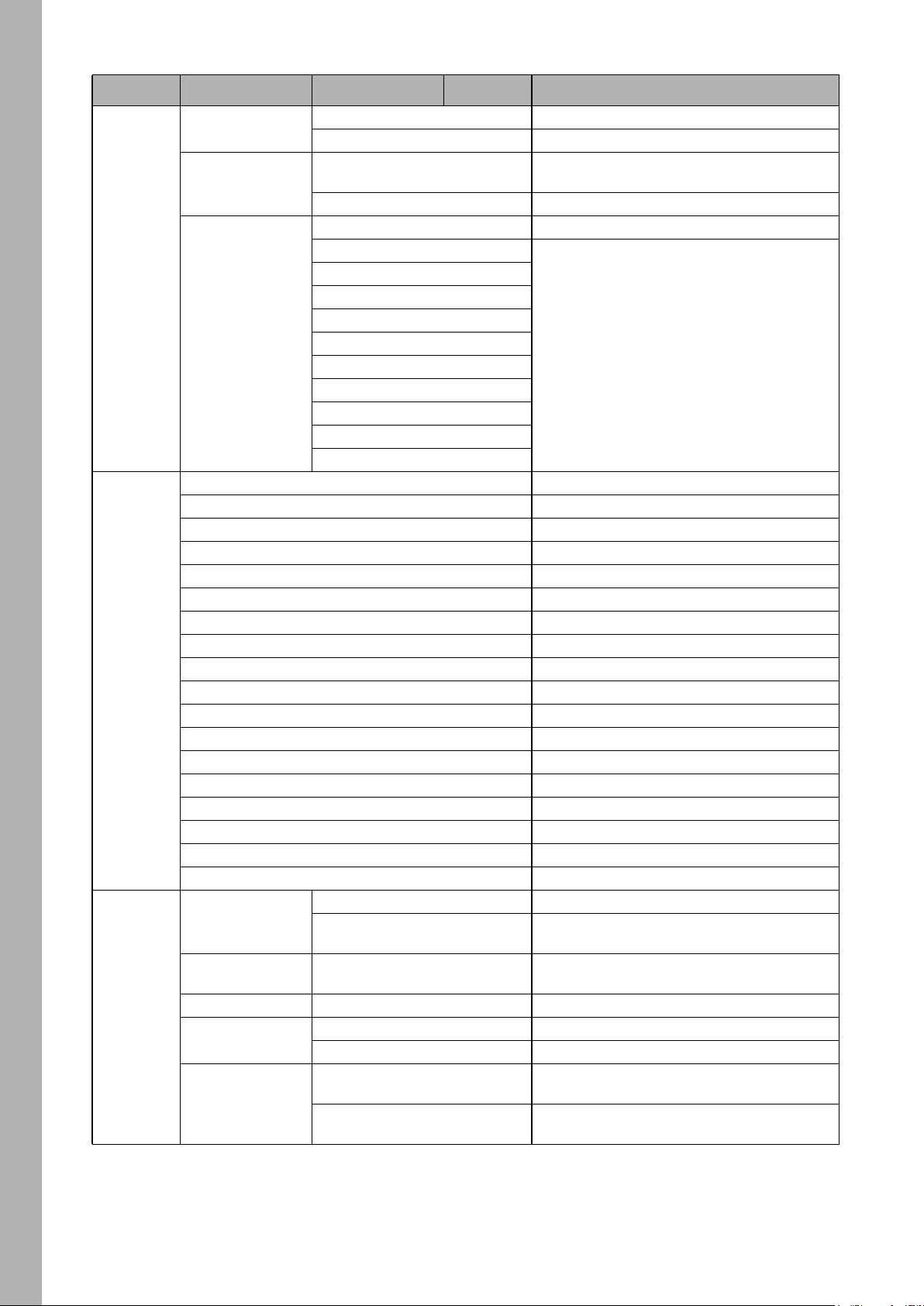
Overview of the Special Control Modes
Control Mode Application Dimming behavior Flicker behavior
Stage Mode Live Audience
Low End Mode TV-Studio, Film Good in low end range Might cause flicker
Tungsten Mode
Normal Mode (no special
control modes active)
Highspeed Mode No dimming --- Flicker free
Simulation of a tungsten
source
Normal dimming
Very good very low end
range
Good through whole
range
Good through whole
range
Will most likely cause
flicker
Might cause flicker
Unlikely to cause flicker
15
15
Page 16

Master/Slave Mode
In Master/Slave mode the slave fixtures mimic the master fixture without delay. The master fixture generates a DMX signal on the 5-pin DMX Thru connector.
Functions
Connect a maximum of 32 SkyPanels and L-series fixtures to a DMX data link. Choose one SkyPanel to
be the master fixture.
There must not be more than one SkyPanel in the data link set to master.
Setting more than one fixture to master or connecting a DMX controller to the data link causes one
or all master fixtures to de-activate the master mode
To set the Master and Slave Fixtures
1.Press the MENU button (10) to open the fixture menu.
2.Turn I/S, until „Light Control“ is displayed. Press I/S to open the menu.
3.Turn I/S, until „Master/Slave Mode“ is displayed. Press I/S to open the menu.
4.Set all fixtures in the data link to „Off“ to de-activate master mode. Select „On“ on one fixture in the data
link to set the fixture as master fixture.
5.Press MENU to close the menu.
All fixtures in the data link will mimic the master fixture automatically and independent from their settings.
Please note when using the master/slave mode:
• Art-Net and sACN are de-activated on all fixtures in the data link.
• Changing the mode on the master fixture (CCT, HSI, GEL, Source Matching, RGBW) changes the mode
on all slave fixtures accordingly.
• Activating the extended color control on the master fixture activates the extended color control on slave
fixtures supporting extended color control.
• The settings DMX protocol version, DMX address, tungsten mode, low end mode, fans and signal loss
behavior are changed accordingly to the settings of the master fixture.
• Connect only C version fixtures of one type in a data link.
• L-series fixtures do not support the GEL mode.
• Presets are not available.
NOTICE
Calibrated RGBW Color Space
When using RGBW mode, the SkyPanel by default does not generate colors in a calibrated color space.
The color is generated with optimized brightness within the specified tolerances. You can activate the calibrated color space Kodak Pro Photo Color Gamut / ESTA standard E1.54 to force the SkyPanel to generate a calibrated color. The calibrated color space is a global setting and is active in both on-board controls
and DMX.
Use the right rotary knob (6) to adjust the portion of the red, green and blue color of the current color. Turn
the knob further to set the white point and green-magenta point of the current color.
To Activate and De-activate the Calibrated RGBW Color Space:
1.Press the MENU button (10) to open the fixture menu.
2.Turn I/S, until „Light Control“ is displayed. Press I/S to open the menu.
3.Turn I/S, until „RGBW Color Space“ is displayed. Press I/S to open the menu.
4.Select „Direct Control“ to generate colors with optimized intensity. Select „Calibrated Color“ to generate
a calibrated color.
5.Press MENU to close the menu.
Frequency Selection
You can change the frequency in the fixture menu. Change the frequency, when you recognize flicker when
in the camera picture or by your eyes. The default frequency is the highest frequency. You can change the
frequency in 10 steps. Frequency 1 is the highest frequency, while frequency 10 is the lowest frequency
setting.
16
Page 17

To set the frequency
1.Press the MENU button (10) to open the fixture menu.
2.Turn I/S, until „Light Control“ is displayed. Press I/S to open the menu.
3.Turn I/S, until „Frequency Selection“ is displayed. Press I/S to open the menu.
4.Select a frequency. Press I/S to confirm the setting. The frequency is set immediately.
5. Press MENU to close the menu.
To set the Fan Mode
You can set the fan mode to adapt the cooling and noise level to the environment. The table below shows
the available options:
FunctionsFunctions
Fan Mode
Normal (only S360-C) 1500 W
Quiet Mode 1200 W
Variable 1200 W
High Temp 1200 W
To set the fan Mode
1.Press the MENU button (10) to open the fixture menu.
2.Turn I/S, until „Fan Mode“ is displayed. Press I/S to open the menu.
3.Select the Fan mode by turning I/S. Press I/S to confirm the setting.
4.Press MENU to close the menu.
Lighting Effects
The SkyPanel offers an effect library with a wide variety of lighting effects used on set or in a TV studio.
The SkyPanel replaces many special effect devices with its unique effect library.
You can call up all effects using the fixture menu or via DMX, Art-Net or sACN. Every effect offers specific
parameters. A lighting effect can be stored in a preset slot for quick access at a later point.
To select and activate an effect
1.Press the MENU button (10) to open the fixture menu.
2.Turn I/S, until „Lighting Effects“ is displayed. Press I/S to open the menu.
3.Select the desired effect by turning I/S.
4.Press I/S to start the effect.
5.Set the parameters, as described below.
To stop an effect
1.Press the MENU button (10) to open the fixture menu.
2.Turn I/S, until „Lighting Effects“ is displayed. Press I/S to open the menu.
3.Select the option „Off“. Press I/S to confirm.
Start / Stop function of the effect
If an effect is running, press I/S to stop the effect execution. Press I/S again to restart the effect from the
beginning. While stopped, the SkyPanel performs a black out and a P:<Effect> shows the status in the display. The start / stop function is only available in the effects control screen.
The SkyPanel provides the following effects in DMX modes 22 (8 bit) and 23 (16 bit):
Max. power
(only S360-C)
Description
The fans operate temperature regulated.
The fans operate constantly at low speed
(silent).
The fans operate temperature regulated.
The fans run at maximum speed.
Party
The Party effect calls up the color spectrum or changes the color temperature from warm to cold and vice versa in an
endless loop.
Parameters:
• Saturation
• Speed
If you do not need the effect for shooting, you will need it for the party when the movie is done!
17
17
Page 18

Functions
Candle
Low flickering of a warm light, slower than fire and less energetic. The light gentle fades in CCT and brightness with periods of static behavior in between. It consists of „flutters“ and static periods.
Parameters:
• CCT range
• Speed
Clouds Passing
Slow variations in intensity and CCT that can be offset. The effect is most useful when using many SkyPanels that are offset to prevent a simultaneous effect on different fixtures.
Parameters:
• Offset
• Passing speed
• Sync
Club Lights
Random colors that pulse, flash and fade.
Parameters:
• Color variety
• Speed
• Sync
Color Chase
Creates a color chasing effect over the surface of the SkyPanel using multiple LED light engines.
Parameters:
• Saturation
• Speed
• Offset
• Sync
Cop Car
Creates an on-board blue and red flashing effect to mimic a police car, an ambulance or a fire brigade. Do
not use the effect in public areas without permission.
Parameters
• Color combination
• Flash pattern
Explosion
A bright flash of light with a fast attack and a semi-slow decay.
Parameters:
• Trigger
• Decay
18
Fire
Creates a flickering fire effect.
Parameters:
• CCT range
• Flicker speed
Fireworks
Bright flashes of color and have a quick start and fade to zero intensity.
Parameters:
• Color combination
• Speed
Page 19

Fluorescent Flicker
Fluorescent color with static periods and then periods of the light flickering on and off.
Parameters:
• Speed
• Frequency
Light Strobe
Generates a white or colored strobe effect with adjustable speed from 25 flashes / sec to 1 flash / sec.
DANGER
DANGER! Risk of injury or death through epileptic seizure.
Do not use the effect near stairways, in corridors or near public exits.
Provide advance notice that strobe lighting is in use. Display advisory notices on the set, at the point
of ticket sales, on tickets if possible, in the program, and at the entrance(s) to the venue or studio.
Avoid extended periods of continuous flashing, particularly at frequencies of 10 to 20 flashes per
second. At flash rates below 5 flashes per second, it is estimated that only 5% of flicker-sensitive
persons will be at risk of seizure
Make sure that personnel at the venue are trained in the care of a person who is having an epileptic
seizure and able to provide care if necessary.
FunctionsFunctions
If strobes are in use and a person has a seizure, switch the strobes off immediately.
Mount strobes as high above head height as practicable.
Parameters:
• CCT
• Green-Magenta point
• Cross fade
• Saturation
• Flash speed
Lightning
Creates an on-board flashing lightning effect. Intensity, speed and frequency of flashing can be controlled.
Parameters:
• CCT
• Green-Magenta point
• Speed
• Frequency
• Sync
Paparazzi
Effect that mimics a flash bulb or modern camera flash.
Parameters:
• CCT
• Flash type
• Frequency
Process
Fading on and off of white light that moves from one light engine to the next.
Parameters:
• Speed
• Direction
19
19
Page 20

Functions
Pulsing
A pulsing or throbbing effect where the color and speed can be set.
Parameters:
• CCT
• Green-Magenta point
• Cross fade
• Color
• Saturation
• Frequency
• Span
Television
Creates an on-board TV effect. Cool CCT that changes intensity every few seconds.
Parameters:
• CCT range
• Speed
Welding
Quick bright flashes on different light engines with a fast decay.
Parameters:
• Speed
• Minimum brightness
To Activate and set Effect Parameters with the Fixture Menu
The rotary knobs adjust the effect parameters when an effect is active. For all effects applies:
• The selected effect is displayed in the left top corner of the display.
• Intensity / Selector adjusts the intensity.
• Press I/S to stop the effect (black out).
• Press I/S again to restart the effect.
• Press MODE long (> 1 sec) to activate the parameters described below (column „Mode“, not available for
all effects).
• Press MODE again to close the effect control and regain normal control.
20
Page 21

The table below shows the parameters you can adjust with the rotary knobs for each effect:
Effect Mode Rotary Knob Parameter
Party Effect
Candle
Clouds Passing
Club Lights
Color Chase
Cop Car
Explosion
Fire
Fireworks
Fluorescent Flicker
Light Strobe
Lightning
Paparazzi
Process
Pulsing
Television
Welding
Central Saturation
Right Speed
Central CCT range
Right Speed
Central Offset
Right Speed
Central Color range
Right Speed
Central Offset
X Central Saturation
Right Speed
Central Color combination
Right Flash pattern
I/S Trigger
Right Decay
X Color mode
Central CCT range
Right Speed
Central Color combination
Right Speed
Central Speed
Right Frequency
X Color mode
X Central Speed
Central Normal functionality
Right Normal functionality
Central Frequency
X Central CCT range
Right Speed
X Right Green-Magenta point
Central Frequency
X Central CCT range
Right Flash bulb
X Right Green-Magenta point
Central Speed
Right Direction
X Color mode
Central Normal functionality
X Central Span
Right Normal functionality
X Right Frequency
Central CCT range
Right Speed
Central Speed
Right Minimum brightness
X Color mode
FunctionsFunctions
21
21
Page 22

When changing a parameter of an active effect through the fixture menu or via DMX, the internal effect generator recalculates the effect in real time. The effect can stutter, step or be unsmooth for a short period. Do
not change parameters of an active effect if the effect needs to run smooth.
Functions
To Set the Display Behavior
You can set the intensity of the background illumination, the contrast, the behavior of the background illumination and the orientation of the display content.
To set the display behavior
1.Press the MENU button (10) to open the fixture menu.
2.Turn I/S, until „Display Setup“ is displayed. Press I/S to open the menu.
3.Turn I/S, until „Display Illumination“ is displayed. Press I/S to open the menu. Select the desired setting
by turning I/S. Press I/S to confirm the setting.
4.Turn I/S, until „Display Brightness“ is displayed. Press I/S to open the menu. Select the desired brightness by turning I/S. Press I/S to confirm the setting.
5.Turn I/S, until „Display Contrast“ is displayed. Press I/S to open the menu. Select the desired contrast by
turning I/S. Press I/S to confirm the setting.
6.Turn I/S, until „Display Rotation“ is displayed. Press I/S to open the menu. Select the desired setting by
turning I/S. Press I/S to confirm the setting.
7.Turn I/S, until „Error Mode Display“ is displayed. Press I/S to open the menu. Select the desired setting
by turning I/S. Press I/S to confirm the setting.
Please refer to section “Overview of the Fixture Menu” on page 31 for a detailed explanation of the options.
USB Functions
To Update the Firmware
1.Copy the SkyPanel update file to the root of an USB memory stick.
2.Connect the USB memory stick to the USB-A connector of the SkyPanel.
3.After a short time the fixture detects the update file on the USB memory stick.
4.Confirm the update with „Yes“.
5.Wait, until the update is finished and the SkyPanel has rebooted with the new firmware.
6.Remove the USB memory stick.
To Update a SkyPanel Remote
The SkyPanel Remote is automatically up- and downgraded by the SkyPanel connected whenever the
firmware versions of the SkyPanel Remote and the SkyPanel are different.
Disconnect all DMX cables from the product before using an USB memory stick. The data transfer
between the product and the USB memory stick might be disturbed due to interferences.
Do not remove the USB memory stick during an update or data transfer. The file system might be
corrupted. You might need to perform a recovery update to return the fixture to a functional state.
The USB-A port can power small USB devices. The maximum current is 500 mA @ 5V. Do not overload the USB-A port.
NOTICE
22
Preset Lists
The fixtures preset list can be saved to an USB memory stick and be uploaded to another SkyPanel.
To Save a preset List
1.Connect an USB memory stick to the USB-A connector of the SkyPanel.
2.Press the MENU button (10) to open the fixture menu.
3.Turn I/S, until „USB Functions“ is selected. Press I/S to open the menu.
4.Turn I/S, until „Save Presets“ is selected. Press I/S to open the menu.
5.Select „Yes“ and press I/S to confirm the setting. Select „No“ to abort saving the preset list.
6.The preset list will be saved on the USB memory stick.
Page 23

Up to 30 preset lists can be stored in the root directory of the USB memory stick. The file name is
<product serial number>-Presetxx.json. The SkyPanel is looking for „Presetxx.json“ to identify a preset
list on an USB memory stick. Be sure to keep the string when renaming a preset list. Otherwise the file will
not be found by the SkyPanel.
To Load a Preset List
1.Connect an USB memory stick with one or more preset lists to the USB-A connector of the SkyPanel.
2.Press the MENU button (10) to open the fixture menu.
3.Turn I/S, until „USB Functions“ is selected. Press I/S to open the menu.
4.Turn I/S, until „Load Presets“ is selected. Press I/S to open the list of the preset lists available in the root
directory of the USB memory stick.
5.Turn I/S, to select a preset list.
6.Press I/S to load the selected preset list. The internal preset list of the SkyPanel will be overwritten by the
selected preset list.
To Save and Load Fixture Settings
The fixtures settings can be saved to an USB memory stick and be uploaded to another SkyPanel. The file
contains all fixture settings except the DMX address and IP settings.
To Save the Fixture Settings
1.Connect an USB memory stick to the USB-A connector of the SkyPanel.
2.Press the MENU button (10) to open the fixture menu.
3.Turn I/S, until „USB Functions“ is selected. Press I/S to open the menu.
4.Turn I/S, until „Save Fix. Settings“ is selected. Press I/S to open the menu.
5.Select „Yes“ and press I/S to confirm the setting. Select „No“ to abort saving the fixture settings.
6.The fixture settings will be saved on the USB memory stick.
Up to 30 fixture settings files can be stored in the root directory of the USB memory stick. The file name is
<product serial number>-Clonexx.json. The SkyPanel is looking for „Clonexx.json“ to identify a fixture
settings file on an USB memory stick. Be sure to keep the string when renaming a fixture settings file. Otherwise the file will not be found by the SkyPanel.
To Load Fixture Settings
1.Connect an USB memory stick with one or more fixture settings files to the USB-A connector of the SkyPanel.
2.Press the MENU button (10) to open the fixture menu.
3.Turn I/S, until „USB Functions“ is selected. Press I/S to open the menu.
4.Turn I/S, until „Load Fix. Settings“ is selected. Press I/S to open the list of the fixture settings files available in the root directory of the USB memory stick.
5.Turn I/S, to select a fixture settings file.
6.Press I/S to load the selected fixture settings. The SkyPanel restarts with the new fixture settings after
successful upload.
FunctionsFunctions
23
23
Page 24

To Save the Error and Service Log
For diagnosis purpose you might be asked to send the error and service log to the ARRI service. The log
files can be downloaded to an USB memory stick.
Functions
The file name contains the date, time and serial number of the fixture.
To save the log files
1.Connect an USB memory stick to the USB-A connector of the SkyPanel.
2.Press the MENU button (10) to open the fixture menu.
3.Turn I/S, until „USB Functions“ is selected. Press I/S to open the menu.
4.Turn I/S, until „Save Error Log“ is selected. Press I/S to open the menu.
5.Select „Yes“ and press I/S to confirm saving the log files. Select „No“ to abort saving the log files.
6.The log files will be saved on the USB memory stick.
To Read out Fixture Settings
1.Press the MENU button (10) to open the fixture menu.
2.Turn I/S, until „Enabled Functions“ is displayed. Press I/S to open the menu.
Change the status of an option by selecting the option. Press I/S, to change the status of the option.
To Read out Fixture Information
1.Press the MENU button (10) to open the fixture menu.
2.Turn I/S, until „Fixture Settings“ is displayed. Press I/S to open the menu.
3.Turn and press I/S to display fixture information.
Please find a detailed overview of the fixture menu in chapter “Overview of the Fixture Menu” on page 31.
To Perform a Factory Reset
1.Press the MENU button (10) to open the fixture menu.
2.Turn I/S, until „Factory Reset“ is displayed. Press I/S to open the menu.
3.Turn I/S to choose the option „Yes“ and perform a factory reset. Press BACK (11) to abort.
4.The SkyPanel reboots with its factory settings.
Light Engine Compensation (C-Versions only)
ARRI always tries to offer lampheads of highest quality and performance. LEDs represent a new type of
light source that is developing rapidly. This is why different SkyPanels can be equipped with different generations of light engines in one installation. In most cases, newer devices achieve higher final brightness
levels due to the further development of LEDs. Light engine compensation is used to adjust the different
brightness levels of the devices.
The final brightness of devices with brighter light engines is limited to ensure the same final brightness for
all devices in the installation.
The Light Engine compensation influences the following control modes:
• CCT
• HSI
• RGBW calibrated
• Gel Mode
• Source Matching
• x,y Coordinates
• Lighting effects
24
Page 25

To Read out Light Engine Information
1.Press the MENU button (10) to open the fixture menu.
2.Turn I/S, until „Fixture Settings“ is displayed. Press I/S to open the menu.
3.Turn I/S, until „LE Compensation“ is displayed. Press I/S to open the menu.
4.Select „Light Engine Status“ and press I/S.
• „LE Gen1 Installed“: The fixture is equipped with Generation 1 Light Engines.
• „LE Gen2 Installed“: The fixture is equipped with Generation 2 Light Engines.
• „LE mixed Gen-Call Service“: The fixture is equipped with drivers or Light Engines of different generations.
The fixture doesn‘t work correctly. This message is mostly due to improper repair attempts. Please contact your ARRI service partner.
To Perform a Light Engine Compensation:
1.Press the MENU button (10) to open the fixture menu.
2.Turn I/S, until „Fixture Settings“ is displayed. Press I/S to open the menu.
3.Turn I/S, until „LE Compensation“ is displayed. Press I/S to open the menu.
4.Select „Light Engine Compensation State“ and press I/S.
5.Select „ON“ to activate Light Engine Compensation, select „Off“ (Default setting) to deactivate.
This function is not available for SkyPanels with Light Engine Generation 1.
6.The SkyPanel adjusts output to match with SkyPanel with LE Gen1 installed.
Please find a detailed overview of the fixture menu in chapter “Overview of the Fixture Menu” on page 31.
FunctionsFunctions
25
25
Page 26

DMX
DMX
Priorities
The fixture can be controlled via DMX, sACN or Art-Net. Please observe the priority rules below when using
more than one control method at a time:.
Control Method Priority
DMX
sACN
Art-Net
DMX Address
When you control the SkyPanel using DMX in a DMX data network, you must assign a DMX address to the
fixture.
To assign a DMX address
1.Press the MENU button (10) to open the fixture menu.
2.Turn I/S, until „DMX Settings“ is displayed. Press I/S to open the menu.
3.Turn I/S, until „DMX Address“ is displayed. Press I/S to open the menu.
4.Select a DMX address. Press I/S to confirm the setting.
5.Press MENU to close the menu.
DMX Mode
The SkyPanel offer different DMX modes. Please find a detailed overview of all DMX modes in the document „SkyPanel DMX Protocol Specification“ which is available for free download on the ARRI website
www.arri.com.
To set a DMX Mode
1.Press the MENU button (10) to open the fixture menu.
2.Turn I/S, until „DMX Settings“ is displayed. Press I/S to open the menu.
3.Turn I/S, until „DMX Mode“ is displayed. Press I/S to open the menu.
4.Select a DMX mode. Press I/S to confirm the setting.
5.Press MENU to close the menu.
DMX commands overwrite sACN and Art-Net commands.
sACN commands overwrite Art-Net commands, but are over-
written by DMX commands.
Art-Net commands are overwritten by sACN and DMX com-
mands.
26
DMX-Signal-Loss Behavior
You can set the behavior of the fixture when the control signal is lost. The table below shows the available
options:
Option Description
Hold Last Command
Black Out
Hold 2 Min. Fade Out
To set the DMX-Signal-Loss Behavior
1.Press the MENU button (10) to open the fixture menu.
2.Turn I/S, until „DMX Settings“ is displayed. Press I/S to open the menu.
3.Turn I/S, until „DMX Loss Behavior“ is displayed. Press I/S to open the menu.
4.Select the setting by turning I/S. Press I/S to confirm the setting.
5.Press MENU to close the menu.
The last received DMX values are used until the fixture is
switched off or valid DMX data is received again.
The fixtures douses to 0% intensity immediately.
The last received DMX values are used for 2 minutes. After 2
minutes the fixture douses to 0% intensity. When valid DMX
data is received after less than 2 minutes, these data will be
used.
Page 27

Wireless DMX
The SkyPanel S360-C is equipped with a wireless DMX receiver supporting the LumenRadio CRMX
protocol.
If there is no DMX traffic received via a wired interface (DMX-512A, ArtNet or sACN) and wireless DMX is
activated via the fixture menu, the SkyPanel S360-C can linked to a wireless DMX transmitter via an RDM
discovery command. Once linked successfully, the SkyPanel S360-C processes wireless DMX data and
respond to RDM requests only via the wireless link.
The DATA LED on the fixture menu panel fades from blue to green followed by a 2 second fade from green
to blue as soon as CRMX is active AND CRMX data is received and processed by the SkyPanel S360-C.
If the WDMX Data State is set to OFF, no wireless DMX and no wireless RDM traffic will be processed.
However, „Unlinking“ and Linking is still possible in State OFF.
To Link a SkyPanel S360-C with a Wireless DMX transmitter
1. Press the MENU button (10) to open the fixture menu.
2. Turn I/S until „DMX Settings“ is displayed. Press I/S to open the menu.
3. Turn I/S until „WDMX Settings“ is displayed. Press I/S to open the menu.
4. Turn I/S until „WDMX State“ is displayed. Press I/S to open the menu.
5. Select the setting „ON“ by pressing the I/S.
6. The fixture can now be detected by a WDMX transmitter. Press MENU to close the menu.
To Unlink a SkyPanel S360-C from a Wireless DMX transmitter
1. Press the MENU button (10) to open the fixture menu.
2. Turn I/S until „DMX Settings“ is displayed. Press I/S to open the menu.
3. Turn I/S until „WDMX Settings“ is displayed. Press I/S to open the menu.
4. Turn I/S until „WDMX Connection Unlink“ is displayed. Press I/S to open the menu.
5. Select the setting „Yes“ by pressing the I/S.
6. The fixture is now unlinked from the transmitter. Press MENU to close the menu.
As soon as DMX or RDM traffic is detected via the other interfaces, any wireless DMX or RDM data will be
ignored and the SkyPanel S360-C processes the wired DMX/RDM traffic.
DMXDMX
NOTICE
Please find a detailed overview of all DMX modes in the document „SkyPanel DMX Protocol Specification“ which is available for free download on the ARRI website www.arri.com.
27
27
Page 28

Networking
Art-Net and sACN
Networking
From firmware version 2.0 the SkyPanel supports Art-Net. Art-Net is a network protocol to control devices.
Here is a brief explanation of some basic terms being used by Art-Net. For more detailed information,
please visit the web site of the Art-Net developers: www.artisticlicence.com.
The SkyPanel is capable of processing Art-Net for up to ten universes with one sender and three universes
with two senders.
Generals rules of thumb:
• Maximum of 4 universes of Art-Net Art-DMX unless you really have to,
• All universes of sACN.
Please find more information about sACN in the standard ANSI E1.31. Please observe all information given
there to set up a proper network.
Art-Net IP Address
When setting the IP address manually, please take care the address is in the range 2.0.0.1 to
2.255.255.255 (Network switch off) or 10.0.0.1 to 10.255.255.255 (Network switch on). Any other range is
not according to the Art-Net standard and problems might occur.
Art-Net Net
A group of 16 consecutive Sub-Nets or 256 consecutive Universes is referred to as a net. There are 128
Nets in total.
Sub-Net
A group of 16 consecutive universes is referred to as a sub-net. (Not to be confused with the subnet mask).
Universe
A single DMX512 frame of 512 channels is referred to as a Universe.
Art-Net Merge Mode
The Art-Net protocol allows multiple nodes or controllers to transmit ArtDmx data to the same universe.Merging is limited to two sources. If there are additional sources, merging will be de-activated.
The Merger can act as an LTP or HTP merger (LTP = Latest Takes Precedence, HTP = Highest Takes
Precedence).
Art-Net Gateway
28
With enabled Art-Net gateway the SkyPanel makes all 512 channels of the used universe available at its
DMX connectors.
The menu „Art-Net Settings“ contains all parameters to set up a SkyPanel in an Art-Net network. Please
find a detailed description in the chapter “Features of the Fixture Menu” on page 7.
The Art-Net gateway is RDM capable. All RDM compatible devices in a network can be detected by the
integrated RDM controller. RDM management over Art-Net is supported.
Page 29

Network Settings
The "Network Settings" menu contains various parameters for setting up the SkyPanel in a network.
Link
Shows whether the SkyPanel is connected to a network.
IP
When the SkyPanel is connected to a network, the display shows its IP address.
Mode
Sets the IP mode. In "DHCP" mode, the IP address, gateway, DNS1 and DNS2 are automatically assigned
to the fixture by the network. You should use this mode if possible.
The parameters "Art-Net 2.x.x.x.x" and "Art-Net 10.x.x.x" are used to set up the fixture in an Art-Net network. "Manual" enables the assignment of a fixed IP address.
Mask
Shows the network mask.
Gateway
Shows the gateway address.
DNS1 / DNS2
DNS addresses of the fixture.
NetworkingNetworking
MAC
Shows the MAC address of the fixture.
BONJ
The SkyPanel can be found automatically in a network via the "Bonjour" application. Activate or deactivate
Bonjour In the "BONJ" menu. You can also set the status via RDM or the Web Portal.
If Bonjour is disabled, the fixture cannot be automatically detected by ARRI Lighting Service Manager.
MDNS
Displays the MDNS address of the fixture (ID and serial number of the device).
ARRI Lighting Service Manager
Please find information about the features and the functionality of the ARRI Lighting Service Manager in
the user manual for the ARRI Lighting Service Manager. You can download it with the ARRI Lighting Service Manager software-bundle from the ARRI web site www.arri.com/lightingsoftware free of charge.
29
29
Page 30

SkyPanel Web Portal
The SkyPanel provides a web page accessible via http, when connected to a network. Type in the IP address of the SkyPanel in your web browser to open the web portal and change the settings listed below.
The web portal can also be found by using a Bonjour service to discover the fixture and open the web portal
Networking
without needing to know the IP address.
The web portal features:
• Select the control mode
• Activate and deactivate lighting effects
• Read and modify DMX settings
• Read and modify network settings
• Read and modify fixture settings
• Read the fixture state
• DMX Monitor
Always use the latest version of your web browser. Earlier versions might not be compatible to the
web portal of the SkyPanel. The following browsers has been tested successful with the ARRI web
portal: Safari, Chrome, Firefox, Opera, IE 11.
Please do not access the web portal during a show. The data exchange with the web portal might
cause delayed reaction and cause unexpected behavior of the fixture.
NOTICE
30
Page 31

Overview of the Fixture Menu
From Firmware-Version 4.2
Open and close the fixture menu the MENU button. BACK closes a sub menu and aborts an action.
Turn INTENSITY / SELECTOR to scroll. Press INTENSITY / SELECTOR to select an item
Level 1 Level 2 Level 3 Level 4 Explanation (default setting = bold)
DMX Address 001 - 512 Start address
DMX Mode P1 - P31 DMX Mode
Hold Last Command Fixture holds the last received control values
DMX Settings
Fan Mode
Light Mode
Light
Control
DMX Loss Behavior
DMX Protocol
Version
Ext. Color Control
RDM State
WDMX Settings
(only S360-C)
Normal (only S360-C) Fans temperature regulated
Quiet Mode Fan speed low
Variable Fans temperature regulated
High Temp Fan speed high
CCT
HSI Colored light, hue and saturation adjustable
Gel
Source Matching The SkyPanel emulates a specific light source.
RGBW Color mixing in RGBW mode.
x,y Coord. Setting the color via its x,y coordinates
Dimming Curve
Special Modes
Black Out Fixture douses the dimmer
Hold 2 Min Fade Out
Version 3.4
Version 4.0
Version 4.1
Version 4.2
Version 4.3
Version 4.4
Off DMX Extended color control not active
On DMX Extended color control active
On RDM communication active
Off RDM communication not active
WDMX State
Connection Unlink Link (NO) or Unlink (YES) fixture
Exponential Exponential dimming curve
Linear Linear dimming curve
Logarithmic Logarithmic dimming curve
„S“ Curve
Low End Mode
Stage Mode
Tungsten Mode
High Speed Mode
On WDMX activated
Off WDMX deactivated
Off Flicker free light
On Optimized dimming at low intensity levels
Off Stage mode OFF
On Stage mode active
Off Color temperature optimized when dimming
On Emulates the behavior of a tungsten light
Off Highspeed mode OFF
On Highspeed mode ON
Hold the last received values for 2 min. then
douse
Version of the DMX protocol
White light, color temperature and green /
magenta correction adjustable
GEL mode, gel library available, color temperature 3.200 K or 5.600 K
Combination of exponential and logarithmic
dimming curve
Overview of the Fixture MenuOverview of the Fixture Menu
31
31
Page 32
Level 1 Level 2 Level 3 Level 4 Explanation (default setting = bold)
Master/ Slave
Mode
RGBW Color
Space
Light
Overview of the Fixture Menu
Control
(cont.)
Lighting
Effects
Display
Setup
Frequency
Selection
Off No stand alone effect
Party Effect Party mode
Candle Candle
Clouds Passing Clouds passing
Club Lights Club light
Color Chase Color chase
Cop Car Cop car
Explosion Explosion effect
Fire Fire
Fireworks Fireworks
Fluorescent Flicker Fluorescent Flicker
Light Strobe Light strobe
Lightning Lightning
Paparazzi Paparazzi
Process Process light
Pulsing Pulsing
Television Television
Welding Welding light
Display
Illumination
Display
Brightness
Display Contrast 01 - 03 - 10 Contrast of the display content
Display Rotation
Display Error
Mode
Off Master/Slave Mode OFF
On Master/Slave Mode active
Direct Control
Calibrated Color The RGBW color is calibrated (optimized hue)
Default Default frequency (highest frequency)
Frequency 1
Frequency 2
Frequency 3
Frequency 4
Frequency 5
Frequency 6
Frequency 7
Frequency 8
Frequency 9
Frequency 10
Always On Display illumination always on
Off After 10 Sec.
0 - 10 Brightness of the display illumination
Normal No rotation of the display content
Upside-Down Display content 180° rotated
Normal
Hidden
The color is mixed in RGBW mode direct (optimized brightness).
Adjusted frequency
Display illumination douses 10 sec. after last
menu action
Show error codes, switch status LED and display illumination to red.
Show error codes. Status LEDs and display
illumination off.
32
Page 33

Level 1 Level 2 Level 3 Level 4 Explanation (default setting = bold)
USB
Functions
Art-Net &
sACN
Network
Settings
Save Light Presets
Light Presets
Fixture Settings
Save Error Log
Art-Net/sACN
State
Art-Net Net 0 - 127 Select Art-Net net
Art-Net Subnet 0 - 15 Select Art-Net subnet in Art-Net net
Art-Net Universe 0 - 15 Select Art-Net universe in Art-Net subnet
Merge Mode
Gateway
sACN Universe 1 ... 65000 sACN universe
IP Mode --> Shortcut to menu „Fixture Settings“.
Link
IP AAA.BBB.CCC.DDD
Mode
Mask 255.255.255.0 Cannot be changed via the fixture menu.
GW x.x.x.x Cannot be changed via the fixture menu.
DNS1 x.x.x.x Cannot be changed via the fixture menu.
DNS2 x.x.x.x Cannot be changed via the fixture menu.
MAC XX:XX:XX:XX:XX:XX MAC address
BONJ
MDNS Sxx-xxxxxxx-xxxx Serial number
Load Light Presets
Save Fix. Settings
Load Fix. Settings [List]
Automatic Accepts both protocols.
Art-Net Only Accepts Art-Net only
sACN Only Accepts sACN only
Off Accepts no network protocol
LTP
HTP
On Gateway disabled
Off Gateway enabled
Connection OK Connection established
No Connection No connection
DHCP Use DHCP mode
Art-Net 2.B.C.D Use Art-Net net 2.B.C.D
Art-Net 10.B.C.D Use Art-Net net 10.B.C.D
Manual Jumps to „IP Address“
On
Off
No
Yes
[List]
No
Yes
Store preset list to an USB memory stick (see
page 22)
Load preset list from an USB memory stick.
Select preset list with Intensity / Selector (see
page 22)
Store fixture settings to an USB memory stick
(see page 23)
Load fixture settings from an USB memory
stick. Select fixture settings with Intensity /
Selector (see page 23)
Store error and service log to an USB memory
stick (see page 24)
Select Merge-Mode „LTP“ (Last Take Precedence)
Select Merge-Mode „HTP“ (High Take Precedence)
The fixtures IP address (assigned via DHCP, if
active)
If manual mode is active:
AAA = 10, 172 or 192
BBB = 0 - 255, 16 - 31 or 168
CCC = 0 - 255
DDD = 0 - 255
If changed, the IP mode is automatically set to
„Manual“
Bonjour State
Overview of the Fixture MenuOverview of the Fixture Menu
33
33
Page 34

Level 1 Level 2 Level 3 Level 4 Explanation (default setting = bold)
Fan Mode
Dim. Curve
Low End
Stage Mode
Tungsten
RGBW C-Space
Enabled
Menu
Overview of the Fixture Menu
Fixture
Info
Fixture
Settings
Factory
Reset
High Speed
Frequency
Master/Slave
Effect
Art-Net/sACN
RDM
Gateway
Bonjour
USB Mode
Fixture Status
Light Engine
Temp.
Hour Counter
Battery Status x.y V Recent voltage of an external battery
Fixture Serial No. L1.xxxxxxx-xxx The fixtures serial number
Firmware
Versions
Low. Batt. Low battery warning treshold
USB Mode
LE Compensation
No Abort action
Yes Load factory settings
Shows the settings of each option. Press I/S to
change the setting of the selected option.
System Ready No error
<error message>
xx.x °C
xx.x °F
xxh - Light Engine
yyh - System
FW: x.xx.xx.xxxx
CP: x.xx.xx.xxxx
Normal USB port powered
Service
Light Engine Status Shows the installed LE generation
LE Compensation
State (not available for fixtures
with LE Gen1
installed)
On Light Engine Compensation active
Off Light Engine Compensation not active
Error message (see „Safety and Installation
manual“)
Recent light engine temperature
Working hours of the light engines and of the
system since production of the fixture
Main firmware version and display firmware
version
USB port not powered. Do not change this
setting unless being asked by ARRI service. Risk of damage!
34
Page 35

RDM Commands
Please find a complete overview of all supported RDM commands for free download on the ARRI website
www.arri.com.
RDM CommandsRDM Commands
35
35
Page 36

Error Codes
Error Codes
36
Code Error Remedy
E.003
Controller over temperature.
STATUS LED lit up red.
E.004 Light engine over temperature
E.005 Missing LED supply.
E.006
Calibration data of light engine
faulty or EEPROM error.
E.007 Invalid PWM value calculation
E.008 Invalid values during calculation
E.009 Invalid values during calculation
E.010
E.011
Fan error. The fan speed deviates or the fan doesn’t run at all.
Fixture menu module not be
detected.
Temperature sensor(s) are
E.012
defective or deviation within
NTC values too high.
E.013 Calibration data faulty.
E.014 Watchdog error
E.015 LED channel faulty
E.016 Boost over temperature
E.018 PWM driver not found
E.019 Diffuser removed
E.020 Update with errors
E.021
Flash init error. No filesystem
mounted.
E.022 Missing Boost
E.023 12V Missing
E.024 5V Missing
E.025 DMX Data Collision
E.026 USB Drive not Mountable
E.027 S360 Slave missing
E.028 Light Engine Missing
E.029
E.030
E.031
DMX JSON Configuration missing or error by loading
New / Old error, only old or new
SPD2 and LE allowed
Problem by Setting Fixture
Factory Default
Let the SkyPanel cool down.Turn the dimmer knob to „0“ or
send an intensity value „0“ via DMX to activate the light
engine again.
See E.003
The LED power supply is faulty. Contact the ARRI service.
WARNING: Loss of calibration data. This error can only be
fixed by re-calibrating the light engine. Please contact the
ARRI service.
Notice: The SkyPanel can be used on. This message is more
a notification than an error.
See E.007
See E.007
All mechanical tests or repairs may only be carried out by a
trained service technician.
If the fixture menu is working, error E.011 can be ignored.
However, if the fixture menu remains dark (no LED lights up)
we recommend to contact the ARRI service. They can then
carry out detailed analyses.
One or more temperature sensors are defective or the deviation within the individual NTCs or BNTCs exceeds the variation tolerance of 12° C / 54° F.
WARNING: Loss of calibration data. Fixture needs to be recalibrated.
Notice: The SkyPanel can be used on. This message is more
a notification than an error.
Notice: The SkyPanel can be used on. This message is more
a notification than an error.
Let the SkyPanel cool down. Turn the dimmer knob to „0“ or
send an intensity value „0“ via DMX to activate the light
engine again.
Switch the SkyPanel off and on again. If the problem persists, please contact the ARRI service.
The diffusor was removed. The protection circuit is active
(only RP-version).
This will be seen if the update process has detected an error
during the update.
This will happen if the flash disc has a problem with its file
system.
Switch the SkyPanel off and on again. If the problem persists, please contact the ARRI service.
The 12V power is missing during startup. Please contact the
ARRI service.
The 5V power is missing during startup. Please contact the
ARRI service.
The fixture detected data on the data line when trying to send
data as a gateway or master fixture. It deactivates the gateway and/or master/slave mode to avoid further data collision.
USB stick can not be mounted. Remove the USB stick, wait
some seconds and reconnect it. If the problem persists, try
another USB stick.
S360 Slave controller not detected. Power cycle the S360. If
the problem persists, please contact your ARRI service
partner.
One or more light engines not detected. Increase the intensity a little to identify the light engine not working. Check the
cable connection of the light engine. If the problem persists,
please contact your ARRI service partner.
Configuration error. Perform a firmware update.
Certain revisions of drivers and light engines are not compat-
ible. Please let the component revisions be checked by your
ARRI service partner.
Factory default load error. Default data corrupted. Perform a
firmware update or contact your ARRI service partner.
Page 37

Overview of Typical CCT Values as DMX Values
D
CCT value DMX value (8 bit) DMX value (16 bit)
Sky-Panel C C
3.200 K 14 3.670
5.600 K 99 25.493
6.000 K 113 29.098
6.500 K 131 33.685
Equations for calculation
To calculate the CCT value
8 bit
DMX
CCT
Value
16 bit
DMX
CCT
Value
To calculate the x,y coordinate
8 bit
DMX
DMX
Value
Value
x Value–
y Value–
DMX
=
DMX
CCT
------------------------------------------=
Value
2800–
28.235
Value
28.2352800+=
2800–
Value
CCT
------------------------------------------
0.109865
Value
=
0.1098652800+=
x
Coordinate
---------------------------------------- -
0.8
y
Coordinate
=
-----------------------------------------
0.8
255
255
16 bit
DMX
MX
x Value–
y Value–
x
Coordinate
=
-----------------------------------------------
0.8
y
Coordinate
=
-----------------------------------------------
0.8
65535
65535
Page 38

Page 39

Page 40

 Loading...