

Page 1
Hi-5 Hand Unit
Hi-5 Hand Unit
U S E R M A N U A L
U S E R M A N U A L
27th July 2021
27th July 2021
Page 2

2
Imprint
Copyright © 2021 Arnold & Richter Cine Technik GmbH & Co.
Betriebs KG. All rights reserved. No parts of this document
may be reproduced without prior written consent of Arnold &
Richter Cine Technik GmbH & Co. Betriebs KG. Specifications
are subject to change without notice. Errors, omissions, and
modifications excepted.
ARRI, ALEXA, AMIRA, Master Grip, LDS and LENS DATA
SYSTEM are trademarks or registered trademarks of Arnold
& Richter Cine Technik GmbH & Co. Betriebs KG. All other
brands or products are trademarks or registered trademarks of
their respective holders and should be treated as such. Original
version.
For Further Assistance
ARRI Cine + Video Geräte Gesellschaft m.b.H.
Pottendorferstraße 23-25/3/1
A-1120 Vienna Austria
E-mail: service@arri.com
Website: www.arri.com
Page 3

3
Scope of this manual
This manual applies to the following product:
K2.0037280 Hi-5 Hand Unit
Revision History
Version ID Order # Release Date
01 10006313 K5.0039972 F07681 2021-07-27
Page 4

4 Contents
1 Contents
1 Contents............................................................................. 4
2 How to Use this Manual................................................... 8
3 For Your Safety............................................................... 10
4 Audience and Intended Use...........................................12
5 Scope of Delivery and Warranty....................................13
6 Introduction to the Hi-5 Hand Unit................................ 14
6.1 Hand Unit Layout....................................................14
6.2 Control Elements.................................................... 19
6.2.1 Knob............................................................19
6.2.2 Slider...........................................................19
6.2.3 Force-Pad................................................... 19
6.3 Buttons.................................................................... 20
6.3.1 Power Button.............................................. 20
6.3.2 REC Button.................................................20
6.3.3 PAGE Button...............................................21
6.3.4 FUNC Button.............................................. 21
6.3.5 Screen Buttons........................................... 21
6.3.6 User Buttons............................................... 22
6.4 Touch Screen.......................................................... 22
6.5 Electrical Interfaces.................................................23
6.5.1 LBUS Interface........................................... 23
6.5.2 SERIAL Interface........................................ 23
6.5.3 USB-C Interface..........................................23
6.5.4 USB-A Interface..........................................23
6.5.5 Radio Module Interface.............................. 24
6.5.6 Smart Ring Interface...................................24
6.6 Screen Pages......................................................... 24
6.6.1 Lens Data Display (LDD)............................24
6.6.2 Camera Screen...........................................26
6.6.3 Menu Screen.............................................. 27
6.7 Radio Modules........................................................27
6.8 Batteries.................................................................. 29
Page 5

Contents 5
7 Preparations.....................................................................31
7.1 Inserting the Battery Pack...................................... 31
7.2 Attaching a Smart Focus Ring................................31
7.3 Attaching a Radio Module...................................... 31
7.4 Setting the language............................................... 32
7.5 Setting Time and Date............................................ 32
8 Controlling Lens and Camera........................................33
8.1 Connecting to Host Device..................................... 33
8.2 Controlling Lens Motors.......................................... 33
8.3 Getting Lens Data on LDD..................................... 34
8.4 Camera Control.......................................................36
8.4.1 ARRI Camera Control.................................37
8.4.2 RED Camera Control..................................37
8.4.3 Sony Camera Control................................. 38
9 Connecting to the ECS Sync App................................. 39
10 Lens Programming......................................................... 40
11 Lens File Management................................................... 41
12 Using Smart Focus Rings.............................................. 43
13 Override Mode................................................................. 44
14 Appendix.......................................................................... 45
14.1 Hi-5 Sets and Accessories..................................... 45
14.2 Dimensions and Weight.......................................... 48
14.3 Electrical Data.........................................................51
14.4 Environmental......................................................... 52
14.5 Service Mode.......................................................... 52
14.6 Service Contacts.....................................................53
14.7 Declarations of Conformity..................................... 56
14.7.1 International declarations............................56
Page 6

6
Disclaimer
Before using the products described in this manual, be sure to
read and understand all the respective instructions.
The ARRI Hi-5 Hand Unit is/are only available to commercial
customers. By utilization, the customer agrees that the Hi-5
Hand Unit or other components of the system are deployed for
commercial use only. Otherwise the customer must contact ARRI
before utilization.
While ARRI endeavors to enhance the quality, reliability and
safety of their products, customers agree and acknowledge that
the possibility of defects thereof cannot be eliminated entirely.
To minimize the risk of damage to property or injury (including
death) to persons arising from defects in the products, customers
must incorporate sufficient safety measures in their work with the
system and heed the stated canonic use.
ARRI or its subsidiaries do not assume any responsibility for
losses incurred due to improper handling or configuration of the
Hi-5 Hand Unit or other system components.
ARRI assumes no responsibility for any errors that may appear
in this document. The information is subject to change without
notice.
For product specification changes after this manual was
published, refer to the latest published ARRI data sheets or
release notes, etc., for the most up-to-date specifications. Not
all products and/or types are available in every country. Please
check with an ARRI sales representative for availability and
additional information.
Neither ARRI nor its subsidiaries assume any liability for
infringement of patents, copyrights or other intellectual property
rights of third parties by or arising from the use of ARRI products
or any other liability arising from the use of such products. No
license, express, implied or otherwise, is granted under any
patents, copyrights or other intellectual property right of ARRI or
others.
ARRI or its subsidiaries expressly exclude any liability, warranty,
demand or other obligation for any claim, representation, cause,
action, or whatsoever, express or implied, whether in contract or
not, including negligence, or incorporated in terms and conditions,
whether by statue, law or otherwise. In no event shall ARRI
Page 7

7
or its subsidiaries be liable for or have a remedy for recovery
of any special, direct, indirect, incidental, or consequential
damages, including, but not limited to lost profits, lost savings,
lost revenues or economic loss of any kind or for any claim by
a third party, downtime, good-will, damage to or replacement of
equipment or property, any cost or recovery of any material or
goods associated with the assembly or use of our products, or
any other damages or injury of the persons and so on or under
any other legal theory.
In the event that one or all of the foregoing clauses are not
allowed by applicable law, the fullest extent permissible clauses
by applicable law are validated.
Page 8

8 How to Use this Manual
2 How to Use this Manual
This manual describes the necessary preparations to start using
the product.
For further details, refer to the
ARRI website at
http://arri.com/hi-5:
All directions are given from a focus puller's point of view. For
example, Hi-5 right side refers to the right side of the Hi-5 when
holding it in two hands, with the focus knob on the right side and
looking at the display.
Connectors are written in all capital letters, for example LBUS.
Menu paths and screens are written in italic typeface, with menu
and LDD in capital letters, for example MENU > Backlight or LDD
> Lens.
Buttons are written in italic typeface capital letters, for example
REC button.
The appendix at the back of the manual contains useful reference
material including Hi-5 technical data, connector pin-out diagrams
and dimensional drawings.
For Tech Tips, please visit the
ARRI Youtube Channel at
https://youtube.com/user/arrichannel:
Additional Information
For useful information in addition to this user manual please have
a look at the ARRI Learn & Help section on the ARRI website.
Page 9

How to Use this Manual 9
Strengthen Your Knowledge and Get Trained
The ARRI Academy courses provide unrivalled insights into the
full possibilities of working with ARRI camera systems, lenses,
lights and accessories.
To learn more, please visit http://arri.com/academy.
Page 10

10 For Your Safety
3 For Your Safety
Before use, please ensure that all users read, understand and
follow the instructions in this document fully.
的用户都已经阅读、理解,并遵循本文档内的操作说明。
Risk levels and alert symbols
Safety warnings, safety alert symbols, and signal words in these
instructions indicate different risk levels:
DANGER
DANGER indicates an imminent hazardous situation which, if
not avoided, will result in death or serious injury.
WARNING
WARNING indicates a potentially hazardous situation which, if
not avoided, may result in death or serious injury.
使用前,请确保所有
CAUTION
CAUTION indicates a potentially hazardous situation which, if
not avoided, may result in minor or moderate injury.
ADVICE
NOTICE explains practices not related to physical injury. No
safety alert symbol appears with this signal word.
Note: Provides additional information to clarify or simplify a
procedure.
Page 11

For Your Safety 11
Vital Precautions
WARNING
Risk of electric shock and fire!
Short-circuits may entail lethal damage!
Before use, read and follow all valid instructions.
Use solely and exclusively as described in the instructions.
Never open. Never insert objects.
For operation, always use a power source as indicated in the
instructions.
Always unplug the cable by gripping the plug, not the cable.
Never try to repair. All repair work should be done by a
qualified ARRI Service Center.
Never remove or deactivate any safety equipment (incl.
warning stickers or paint marked screws).
Always protect from moisture, cold, heat, dirt, vibration, shock,
or aggressive substances.
General precautions
Use only the tools, materials and procedures recommended in
this document. Unplug all cables during transport.
ADVICE
Do not store the Hi-5 Hand Unit in places where it/they may be
subject to temperature extremes, direct sunlight, high humidity,
severe vibration, or strong magnetic fields.
Page 12

12 Audience and Intended Use
4 Audience and Intended Use
The Hi-5 Hand Unit is solely and exclusively for use on
professional camera setups.
ADVICE
The product is solely and exclusively available for commercial
costumers and shall be used by skilled personnel only. Every
user should be trained according to ARRI guidelines.
Use the product only for the purpose described in this
document. Always follow the valid instructions and system
requirements for all equipment involved.
Page 13

Scope of Delivery and Warranty 13
5 Scope of Delivery and Warranty
Delivery
A complete delivery of the KK.0039973 Hi-5 Hand Unit Body Kit
includes:
1x Hi-5 Hand Unit Body (K2.0037280)
•
1x Bluetooth Dongle (K2.0039838)
•
1x Smart Focus Ring Blank (K2.0037463)
•
1x User manual
•
1x Original packaging
•
ADVICE
On delivery, please check if package and content are intact.
Never accept a damaged/incomplete delivery.
ADVICE
Product and packaging contain recyclable materials. Always
store, ship and dispose according to local regulations.
ARRI is not liable for consequences from inadequate storage,
shipment or disposal.
ARRI offers an increasing variety of product bundles and
additional accessories. For details, please consult our website or
your local ARRI Service Partner.
Warranty
For scope of warranty, please ask your local ARRI Service
Partner. ARRI is not liable for consequences from inadequate
shipment, improper use or third-party products.
Page 14

14 Introduction to the Hi-5 Hand Unit
6 Introduction to the Hi-5 Hand Unit
The ARRI Hi-5 hand unit provides reliable wireless camera and
multi-axis lens control in demanding situations on set. Robust and
weatherproof, it features unique, swappable radio modules for
different territories and shooting challenges, ensuring the best
possible radio link range for every setup.
Hi-performance: strong radio signal over long distances
•
Hi-versatility: swappable radio modules for different
•
locations
Hi-speed: fast and efficient on-set ecosystem
•
Hi-tech: future-proof hardware and software architecture
•
Hi-reliability: robust, weatherproof, long battery life
•
6.1 Hand Unit Layout
Front Side
Page 15

Introduction to the Hi-5 Hand Unit 15
Right Side
Left Side
Page 16

16 Introduction to the Hi-5 Hand Unit
Back Side
Top Side
Page 17

Introduction to the Hi-5 Hand Unit 17
Bottom Side
1 REC Button
2 REC Status LED
3 Ambient Light Sensor
4 PAGE Button
5 Upper Screen Buttons
6 Backlit Ring Area
7 Smart Ring Interface (Pogo Pins)
8 Registration Pin
9 Front Knob Index
10 Control Knob
11 Lower Screen Buttons
12 Power Button
13 FUNC Button
Page 18

18 Introduction to the Hi-5 Hand Unit
14 Slider
15 Touch Screen
16 Force-Pad
17 Friction Adjustment
18 Snaphook Eyelet
19 Snaphook/Hand Strap Eyelet
20 Radio Release Button
21 Radio Module Interface
22 Hand Strap Eyelet
23 Back Knob Index
24 SERIAL Connector
25 LBUS Connector
26 User Buttons
27 Nato-Rail Security Pin
28 Nato-Rail
29 3/8" -16 UNC and 1/4" - 20 UNC Mounting Interfaces
30 USB-C Interface
31 USB-A Interface
32 Battery Compartment
33 M4 Mounting Interfaces
Page 19

Introduction to the Hi-5 Hand Unit 19
6.2 Control Elements
6.2.1 Knob
The knob can control focus, iris and zoom motors and is set to
control the focus motor by default. It features a friction adjustment
mechanism and two Pogo pins to ARRI's Smart Focus Rings. The
integrated backlight lets the focus ring glow in white, red, green,
blue, yellow, magenta or cyan colors.
Turn the knob counterclockwise to focus towards infinity and turn
it clockwise to focus towards close focus in the default setting.
Press PAGE to enter the MENU, select Control Setup > Knob and
tick the Reverse checkbox to change the direction.
6.2.2 Slider
The slider can control focus, iris and zoom motors and is set to
control the iris motor by default.
Move the slider upwards to open the iris and move it clockwise
to close the iris. Press PAGE to enter the MENU, select Control
Setup > Slider and tick the Reverse checkbox to change the
direction.
6.2.3 Force-Pad
The Force-Pad can control focus, iris and zoom motors and is set
to control the zoom motor by default.
Push the Force-Pad upwards to zoom in and push it down to
zoom out in the default setting. Press PAGE to enter the MENU,
select Control Setup > Force-Pad and tick the Reverse checkbox
to change the direction.
In menu mode, the Force-Pad can be used to navigate through
the menu. It navigates in x- and y-directions, making it a good
alternative to the touch screen. Also, use User Button 3 to select
a menu item and use User Button 2 to go one level back.
Page 20
20 Introduction to the Hi-5 Hand Unit
6.3 Buttons
6.3.1 Power Button
Press the Power button momentarily to switch the hand unit on.
Keep it pressed for two seconds to switch the hand unit off.
Pressing the Power button twice locks all control elements,
buttons and the touch screen. Press the Power button twice again
to unlock the hand unit.
6.3.2 REC Button
Press the REC button briefly to start recording. The REC Status
LED will change to red color (with cameras supporting tally
feedback).
Press the REC button again to stop recording.
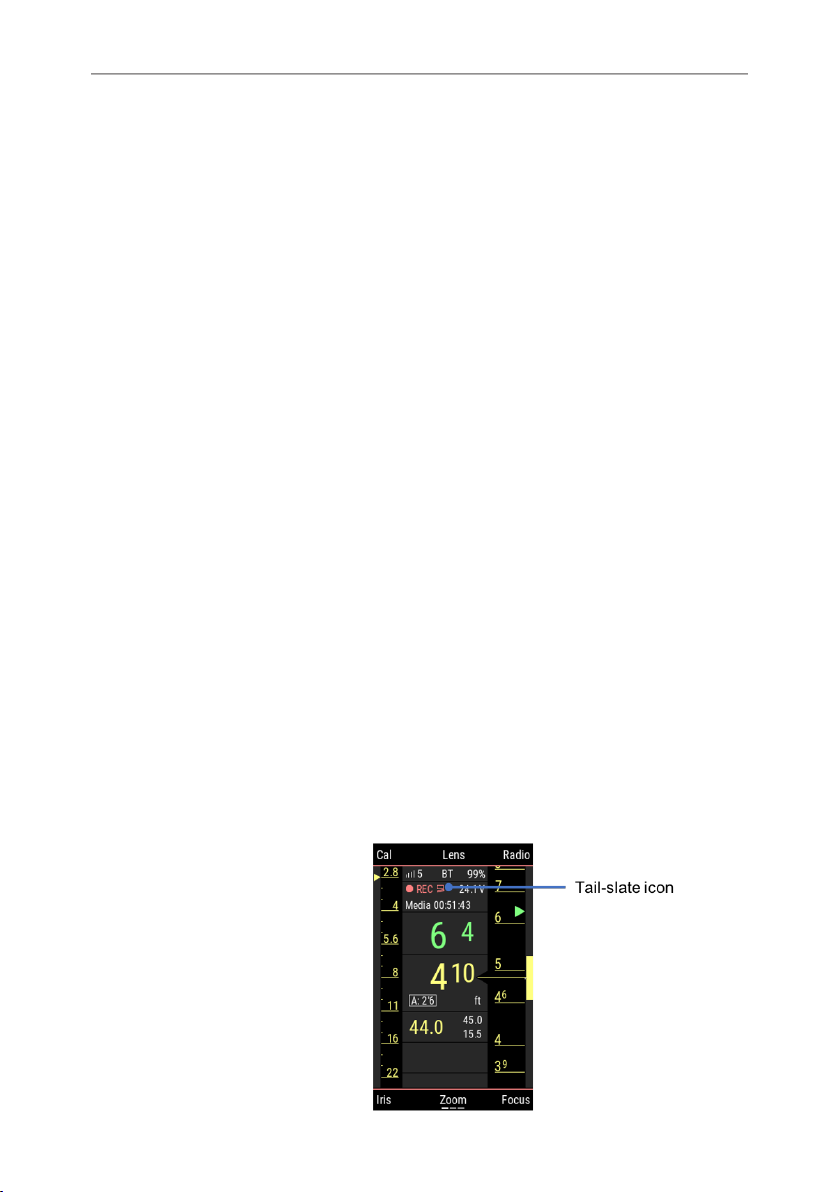
Tail-Slate Mode
Hi-5 provides an tail-slate recording mode that prevents you from
stopping recording before the tail-slate is taken.
Use the tail-slate mode as follows:
1. Press the REC button for 1 second start recording. A red endslate icon will appear on the Lens Data Display, indicating that
tail-slate mode is active.
2. Capture the tail-slate at the end of the shot.
3. Press the REC button again for 1 second to stop recording.
Page 21

Introduction to the Hi-5 Hand Unit 21
Pressing the REC button briefly during recording in tail-slate
mode will not stop the recording, but generate a warning that
tail-slate mode is active.
6.3.3 PAGE Button
Use the PAGE button to switch between screens. The default
screen is the Lens Data Display (LDD).
Pressing PAGE button once switches the display to the Camera
screen (if Hi-5 is connected to a camera supporting this feature).
Pressing the PAGE button again switches to the MENU screen.
6.3.4 FUNC Button
Pressing the FUNC button shifts the screen button functionalities
to additional levels. Additional function levels are indicated by
tiny bars on the lower edge of the screen, above the lower center
screen button.
6.3.5 Screen Buttons
Six screen buttons are located above and below the display.
They change their behavior depending on the screen content,
indicating the function related to each button. Buttons without a
label have no function on that screen.
Page 22

22 Introduction to the Hi-5 Hand Unit
6.3.6 User Buttons
The three user buttons on the back of the handgrip can be
individually assigned. Use the PAGE button and go to MENU >
User Buttons to assign a function for each user button.
In Menu and Lens Programming mode, use User Button 3 to
select an item and use User Button 2 to go one level back.
6.4 Touch Screen
The touch screen supports tap, swipe, pinch and stretch gestures.
Gesture How to do it
Tap Tap the screen to perform an action.
Swipe A movement of a fingertip across the screen in
a vertical or horizontal direction.
Stretch Pressing two fingers together on the screen,
move them away from each other as if stretching them apart.
Pinch Pressing two fingers apart on the screen,
move them towards each other as if pinching
them together.
On the Lens Data Display, swipe left to enter the MENU screen
and swipe right to return.
Swipe right to enter the Camera screen (if available) and left to
return.
Tap on a screen button label to enter.
Pinch and stretch in vertical direction to compress or expand the
on-screen focus scale.
In the Menu, swipe up or down to scroll. Tap on a menu item to
enter or select.
Page 23

Introduction to the Hi-5 Hand Unit 23
6.5 Electrical Interfaces
6.5.1 LBUS Interface
The LBUS interface at the back of the hand unit communicates
LBUS and LCS protocols. It can be used to hardwire the Hi-5
to ARRI camera hosts, to control panels of ARRI's Camera
Stabilizing Systems and to other LBUS devices.
6.5.2 SERIAL Interface
The SERIAL connector is for future use.
6.5.3 USB-C Interface
The USB-C interface is placed under a rubber lid on the Hi-5 top
side. It can be used for the following:
Software updates via flash drive (supports USB-C card
•
readers as well)
Exchange of lens files and user setup files via flash drive
•
(supports USB-C card readers as well)
External power supply
•
IP connection to a laptop for entering the service mode
•
through a web browser
6.5.4 USB-A Interface
The USB-A interface is placed under a plastic cover on the
bottom side of the Hi-5 hand unit. It contains a Bluetooth stick for
connecting to the ECS Sync app.
Besides establishing a connection to the ECS Sync app via
Bluetooth stick, the USB-A interface can be used for the following:
Software updates via flash drive (supports USB-C card
•
readers as well)
Exchange of lens files and user setup files via flash drive
•
(supports USB-C card readers as well)
Page 24

24 Introduction to the Hi-5 Hand Unit
6.5.5 Radio Module Interface
The RIA-1 contains a radio module interface for ARRI's
exchangable radio modules (RF-EMIP Radio Module 2400 MHz
DSSS, RF-2400 Radio Module 2400 MHz FHHS and RF-900
Radio Module 900 MHz FHHSS).
ATTENTION
Always keep the Radio Interface clean and dry!
Do not leave the Radio interface open during transportation
and storage. Attach the RF Cover or a radio module instead
6.5.6 Smart Ring Interface
The Hi-5 knob contains two spring-loaded pins as an interface
for ARRI's Smart Focus Rings. They establish an electrical
connection between the chip on a Smart Focus Ring and the Hi-5
hand unit.
6.6 Screen Pages
6.6.1 Lens Data Display (LDD)
The Lens Data Display (LDD) is the default screen. It displays
the most important parameters of the hand unit and the host of
the camera side, and shows the current position of the motors
attached to the focus, iris and zoom lens rings.
The distance readout of compatible measuring devices such as
the Ultrasonic Distance Measure UDM-1, Cine RT, Cine Tape,
Ward Sniper or cfinder III will automatically appear on the LDD
screen if connected to the respective camera host. The distance
readout is displayed as a number above the focus value in the
center of the LDD screen and as an arrow on the LDD focus
scale.
Page 25

Introduction to the Hi-5 Hand Unit 25
Motor Trails
The scales on the Hi-5 Lens Data Display represent the current
position of the knob and slider controls. Fast focus and iris racks
can result in an offset between those target values and the actual
position of the lens rings, as the lens motor can take more time
to travel to the desired position than the focus knob and iris slider
do. Such an offset is indicated by the focus and iris trails that are
represented as a white line next to the focus and iris scales.
Page 26

26 Introduction to the Hi-5 Hand Unit
Depth-of-Field Bar
The yellow depth-of-field bar right to the focus scale indicates the
distance range between the nearest and the farthest objects that
are in acceptably sharp focus.
It is calculated based on focal length (zoom setting), focus
distance (focus setting), aperture (iris setting), and the circle of
confusion size.
While focal length, focus distance and aperture depend on the
physical settings of the lens, the circle of confusion can be set as
a numerical value in the hand unit.
6.6.2 Camera Screen
The Camera screen shows the camera status and the name
of the active lens file. It also allows changing basic camera
parameters.
The Camera screen will display whenever a digital ARRI camera
is connected. For RED and Sony cameras, an additional license
is required.
Page 27

Introduction to the Hi-5 Hand Unit 27
6.6.3 Menu Screen
The MENU contains all parameters for setting up the Hi-5 hand
unit as well as connected accessories such as motors and
distance measurers.
Use the PAGE button and go to MENU > System to perform
software updates, manage licenses and download log files.
6.7 Radio Modules
ARRI offers three different exchangeable radio modules for
various shooting conditions and regions.
Page 28

28 Introduction to the Hi-5 Hand Unit
WARNING
For further information, please refer to the manual of the
respective products.
RF-EMIP Radio Module
The RF-EMIP radio module is backwards-compatible to devices
including the ARRI's white-coded radio (EMIP) modules (e.g.
ALEXA Mini, cforce mini RF). It can establish a point-to-multipoint
communication for connecting up to three hand units with one
camera device.
Frequency: 2400 MHz
Modulation: Direct-sequence spread spectrum (DSSS)
Number of
channels:
14
RF-2400 Radio Module
The RF-2400 can establish a point-to-point communication for
connecting one Hi-5 hand unit with one Radio Interface Adapter
RIA-1 with the corresponding RF-2400 radio module.
Its frequency hopping transmission method ensures a strong
radio link with exceptionally good interference immunity.
Frequency: 2400 MHz
Modulation: Frequency-hopping spread spectrum
(FHSS)
Number of
channels:
100
RF-900 Radio Module
The RF-900 radio module can establish a point-to-multipoint
communication for connecting up to three hand units with one
camera device.
Page 29

Introduction to the Hi-5 Hand Unit 29
Its frequency hopping transmission method ensures a strong
radio link with exceptionally good interference immunity.
Frequency: 900 MHz
Modulation: Frequency-hopping spread spectrum
(FHSS)
Number of
channels:
100
WARNING
The RF-900 radio module is for usage in USA and Canada
only!
ADVICE
When removing the radio modules from the hosting units (Hi-5
Hand Unit, Radio Interface Adapter RIA-1), please check the
temperature of the radio modules first. If they are hot, please
wait until they have cooled down.
ADVICE
The RF-2400 and RF-900 radio modules need to be attached
to the Radio Interface Adatpter RIA-1 on the camera side.
6.8 Batteries
We recommend using ARRI's LBP-3500 Li-Ion batteries for the
Hi-5 hand unit.
The LBP-3500 batteries have a capacity of 3,500 mAh. They
include a chip that communicates the capacity of the battery to
the hand unit in real-time. They hand unit accurately displays the
remaining capacity in %.
Page 30

30 Introduction to the Hi-5 Hand Unit
The Hi-5 hand unit is compatible to the L-Series battery
interface and works with respective 3rd-party batteries such
as NP-F550 type batteries. However, there is no accurate
capacity display with these batteries and the hand unit can
shut off abruptly without warning.
Page 31

Preparations 31
7 Preparations
7.1 Inserting the Battery Pack
1. Open the battery compartment.
2. Insert the ARRI LBP-3500 battery pack.
3. Close the battery compartment.
ADVICE
Use the LBP Battery Charger to charge the battery before use.
7.2 Attaching a Smart Focus Ring
1. Go to MENU > Premarked Ring and select Auto.
2. Slide the ring onto the knob so that the notch on the ring
meets the registration pin on the knob.
3. The ring will be automatically detected by the Hi-5 hand unit.
7.3 Attaching a Radio Module
1. Press the Radio Release Button and remove the RF Cover by
sliding it upwards.
2. Insert the radio module by fitting it into the radio module slot
and sliding it downwards until the Radio Release Button pops
back out.
Page 32

32 Preparations
ADVICE
You always need the same type of radio module on the camera
side!
If you use an RF-2400 or RF-900 radio module with Hi-5, you
need the same on the camera side, attached to the Radio
Interface Adapter RIA-1.
If you use the RF-EMIP module, you are compatible with the
white-coded radio module built in ARRI cameras and motor
controllers.
7.4 Setting the language
The graphical user interface of the Hi-5 is available in English,
Chinese, Spanish and German language.
1. Go to MENU > System > Language.
2. Select your desired language.
7.5 Setting Time and Date
The Hi-5 provides log file generation for service purposes.
Time and date are essential information for those log files. It is
therefore recommended to set time and date before use.
1. Go to MENU > System > Timezone.
2. Select the timezone you are in.
3. Go to the menu item displaying Date/Time and set the current
date and time.
Page 33

Controlling Lens and Camera 33
8 Controlling Lens and Camera
8.1 Connecting to Host Device
1. Press the Radio button on the LDD screen.
2. Select the same radio channel as set on the corresponding
camera host.
3. Switch the radio transmission on by ticking the Power
checkbox.
4. Return to the LDD screen by pressing the back or PAGE
button.
The selected radio channel will be indicated in the top center area
of the LDD screen. A signal strength indicator will be displayed
as soon as a connection between Hi-5 and camera host is
established.
ATTENTION
Any region setting set in the Hi-5 Radio Menu prior to
connecting to a host device will be overruled by the region
setting of the host device.
Make sure that the selected region setting fits your location.
It may not be legal to operate the Hi-5 hand unit with the
attached radio module in a country/region other than the
country/region set in the Hi-5 radio system. Switch the radio off
and use the device in hardwired mode if you are unsure of the
correct region setting.
8.2 Controlling Lens Motors
1. Connect the lens motors to the camera host device and
power up. In case you use cforce motors, assign each motor
to the respective lens axis (see cforce motor user manual for
details).
2. Power up the hand unit by pressing the POWER button.
Page 34

34 Controlling Lens and Camera
3. Connect to the host device. A calibration request will appear
on the LDD screen.
4. Calibrate all lens motors by pressing the Cal screen button
twice.
You can now use knob, slider and Force-Pad to control the
motors they are assigned to. You can change the control for a
lens motor at MENU > Control Setup.
8.3 Getting Lens Data on LDD
The Lens Data Display (LDD) shows the current settings of
the lens. It provides numerical values for the focus and zoom
settings, as well as iris and focus scales. The yellow depth-of-field
bar right to the focus scale indicates the distance range between
the nearest and the farthest objects that are in acceptably sharp
focus.
Lens data in generated with encoder values representing the
physical settings of the lens rings and a lens file translating those
values into human-readable numbers. In case you use an LDS
lens on an ARRI camera, you will get lens data instantly. In case
you use a non-LDS lens, the encoder values are generated by
the lens motors and you have to manually load the corresponding
lens file.
Wireless Lens File Transfer
The Hi-5 hand unit can transfer lens files wirelessly to the
following devices:
ALEXA Mini camera
•
ALEXA Mini LF camera
•
Universal Motor Controller UMC-4
•
cforce mini RF lens motor
•
To transfer a lens file wirelessly from Hi-5, do as follows:
Page 35

Controlling Lens and Camera 35
1. Go to LDD > Lens > Lens Files.
2. Select the lens file.
3. Press use to send the lens file to the camera device and
activate it there.
Lens File Transfer with External Flash Drive
Lens file transfer with an external flash drive is required for the
following devices:
All ALEXA Classic cameras including the Plus Module
•
(ALEXA Plus, ALEXA SXT, ALEXA LF, ALEXA 65)
To transfer a lens file with an external flash drive from Hi-5, do as
follows:
1. Prepare an SD card with the following folder structure: ARRI/
ALEXA/LDA .
2. Attach a card reader with the SD card in it to the USB-C port
of the Hi-5.
3. Go to LDD > Lens > Lens Files.
4. Press FUNC to enter FUNC Level 2.
5. Select Internal Lens File and select the lens file you want to
transfer to the camera.
6. Press the FUNC button to select whether to copy or move the
lens files to the SD card.
7. Navigate to the folder ARRI/ALEXA/LDA .
8. Press export to transfer the lens files to the folder on the SD
card.
9. Remove the SD card from Hi-5 and insert it to the camera.
10. Load the lens files into the camera.
Setting the Circle of Confusion
The yellow depth-of-field bar right to the focus scale indicates the
distance range between the nearest and the farthest objects that
are in acceptably sharp focus.
Page 36

36 Controlling Lens and Camera
It is calculated based on focal length (zoom setting), focus
distance (focus setting), aperture (iris setting), and the circle of
confusion size.
While focal length, focus distance and aperture depend on the
physical settings of the lens, the circle of confusion can be set as
a numerical value in the hand unit.
To set the circle of confusion, do as follows:
1. Go to LDD > Lens > Circle of Confusion.
2. Select a circle of confusion diameter.
ADVICE
The perceived sharpness of an image depends on the lens
characteristics, the camera sensor and image processing,
the scene content, the setting of the lens and eventually the
display the image is viewed on.
The depth-of-field bar on a hand unit is just an indication for
the distance range in which objects appear in acceptably sharp
focus.
Always test the actual depth-of-field of your setup before
shooting and adjust the circle of confusion if needed.
As a guideline, we recommend the following circle of confusion
settings:
0.013mm For maximum detail contrast on Super 35 cameras.
0.025mm Standard setting for Super 35 cameras.
0.035mm Standard setting for Large Format cameras.
0.050mm Standard setting for 65mm cameras.
8.4 Camera Control
The Hi-5 hand unit provides remote camera setup capabilities for
ARRI and third-party cameras. ARRI camera control is included
by default, third-party camera control requires additional licenses.
Page 37

Controlling Lens and Camera 37
8.4.1 ARRI Camera Control
The Hi-5 hand unit provides remote camera setup capabilities
for ALEXA cameras, as well as for AMIRA if combined with the
Universal Motor Controller UMC-4 or the cforce mini RF lens
motor. This does not require an additional license. The following
functions are supported:
Full Playback Control (ALEXA Mini/Mini LF/AMIRA)
•
Sensor Frame Rate
•
Shutter Angle
•
Exposure Index
•
White Balance
•
ND Filter (ALEXA Studio and ALEXA Mini/Mini LF/AMIRA)
•
Peaking on Monitor Output (on/off)
•
Surround View on Monitor Output (on/off)
•
False Color on Monitor Output (on/off)
•
Status Info on Monitor Output (on/off)
•
Frame Lines on Monitor Output (on/off)
•
User Buttons
•
Camera User Setups (ALEXA Mini/Mini LF)
•
8.4.2 RED Camera Control
RED camera control is available with Hi-5 and the Radio Interface
Adapter RIA-1 as well as the cforce mini RF lens motor (SUP
2 onwards). It requires the RED Camera Control License Key
installed on Hi-5.
The RED Camera Control License Key unlocks remote control
of frame rate, shutter angle, ISO, white balance, playback and
camera user buttons. Supported features depend on camera
model and camera settings.
Page 38

38 Controlling Lens and Camera
8.4.3 Sony Camera Control
Camera control for Sony Venice is available with Hi-5 and the
Radio Interface Adapter RIA-1 as well as the cforce mini RF lens
motor (SUP 2 onwards). It requires the Sony Camera Control
License Key installed on Hi-5.
The Sony Camera Control License Key unlocks remote control of
frame rate, shutter angle, ISO, white balance, ND filters, playback
and camera user buttons. Supported features depend on camera
model and camera settings.
Page 39

Connecting to the ECS Sync App 39
9 Connecting to the ECS Sync App
The ARRI ECS Sync App runs on iOS devices and can be
downloaded from the App Store for free. It provides the following
functions:
Managing, visualizing and sharing lens files
•
Managing and sharing Hi-5 user setup files
•
Performing software updates on Hi-5 and connected LBUS
•
devices
News and FAQs
•
The ECS Sync App connects to Hi-5 via Bluetooth. To add your
Hi-5 to the list of Bluetooth devices on your iOS device, do the
following:
1. Go to MENU > System > Bluetooth.
2. Activate Bluetooth on your iOS device and add the Hi-5 to
your device list (Hi-5 is shown as hi-5-xxxxx, with xxxxx being
the serial number).
3. Open the ECS Sync App. The app is now connected to your
Hi-5 hand unit.
Page 40

40 Lens Programming
10 Lens Programming
Lens files are needed to generate lens data for the Lens Data
Display, focus mapping to premarked focus rings, focus tracking
and as metadata in mixed reality or post production.
Follow these steps to program a lens file:
1. Go to LDD > Lens > Lens Programming.
2. Calibrate the lens motors or skip calibration if they are
calibrated already.
3. Follow the on-screen guidance and enter the lens brand, type
and focal length, serial number and focus unit.
4. Select the Focus, Iris or Zoom axis to enter the data points.
Use the FUNC button to toggle through the available options:
add Add a value
value Show the value on the Lens data Display
line Show the line on the Lens data Display
snap Snap to the nearest value to the current posi-
tion of the control element.
move Move a single mark.
offset Move the whole scale.
delete Delete a selected mark.
back Quit programming a scale wihout saving.
finish Finish programming the axis.
Page 41

Lens File Management 41
11 Lens File Management
Hi-5 contains an internal memory space for storing lens files.
There are two ways of exchanging lens files with external
devices:
1 ECS Sync app (iOS)
2 USB-C interface
Transferring Lens Files from Hi-5 to App
Connect Hi-5 with the ECS Sync App. Then do the following:
1. Open the ECS Sync App.
2. Go to the ARRI Device tab.
3. Tap on the icon of the connected Hi-5.
4. Go to Lens Files and mark the checkboxes of the lens files to
be transferred.
5. Tap on the Download icon on the lower left of the app screen.
6. Select the location you want to download the files to in your
app. This can be the app's root folder, an existing folder or
you can create a new folder.
7. Tap on "Download here" to perform the download.
Transferring Lens Files from App to Hi-5
Connect Hi-5 with the ECS Sync App. Then do the following:
1. Open the ECS Sync App.
2. Go to the Phone tab.
3. Mark the checkboxes of the lens files you want to transfer.
4. Tap on the Upload icon on the lower left of the app screen.
5. Select the Lens Files folder.
6. Tap on "Upload here" to perform the upload.
Page 42

42 Lens File Management
Transferring Lens Files from External Flash Drive
to Hi-5
Connect an external flash drive to the USB-C connector. Then do
the following:
1. On the Lens Data Display, press Lens.
2. Select Lens Files.
3. Press the FUNC button to enter the second function level.
4. Select External Lens Files.
5. Select the lens files you want to import.
6. Press import to import the selected lens files to the internal
memory of Hi-5.
Transferring Lens Files from Hi-5 to External Flash
Drive
Connect an external flash drive to the USB-C connector. Then do
the following:
1. On the Lens Data Display, press Lens.
2. Select Lens Files.
3. Press the FUNC button to enter the second function level.
4. Select Internal Lens Files.
5. Select the lens files you want to export.
6. Press the FUNC button to select whether to copy, move or
erase the selected lens files.
7. If you have selected copy or move, then press the FUNC
button again to decide whether to export the lens files to the
ARRI/Hi-5/LDA folder on the external drive or if you want to
add a new folder on the external drive to store the files in.
8. Create a new sub-folder if needed and press export to export
the files to the selected folder on the external drive.
Page 43

Using Smart Focus Rings 43
12 Using Smart Focus Rings
ARRI's Smart Focus Rings are a set of premarked focus rings
that include a chip containing information about the premarked
scale on the ring.
Smart Focus Rings can be automatically detected by the Hi-5
hand unit. To use a Smart Focus Ring, do as follows:
1. Go to MENU > Premarked Ring and press auto.
2. Slide the ring onto the knob so that the notch on the ring
meets the registration pin on the knob.
The ring will be automatically detected by the Hi-5 hand unit.
ADVICE
Focus mapping to premarked rings requires lens data. Use an
LDS lens or load a lens file for lens mapping.
Page 44

44 Override Mode
13 Override Mode
The Override function enables operators to override and return
focus, iris or zoom control at the touch of a button on the Operator
Control Unit OCU-1 or the Master Grips.
The Hi-5 indicates the Override mode and enables a smooth
transition.
OCU-1/Master Grip overrides focus control from Hi-5. Hi-5 focus scale turns red.
Hi-5 has no control over focus axis.
Return focus control to Hi-5 on the
OCU-1/Master Grip or by pressing the FOVR button on the Hi-5. The Hi-5 focus
scale turns green. The focus knob is still
offset (see motor trail at the currently set
motor position).
Pull the motor trail towards the index line
by turning the focus knob until the trail diappears. The Hi-5 re-engages with the
lens motor.
Page 45

Appendix 45
14 Appendix
14.1 Hi-5 Sets and Accessories
Hi-5 Sets
K0.0040721 Hi-5 Hand Unit Basic Set
K0.0040726 Hi-5 RX-TX 2400 Set
K0.0040724 Hi-5 RX-TX 900 Set
K0.0040727 Smart Focus Ring Set Feet
K0.0040728 Smart Focus Ring Set Meter
Hi-5 Parts
KK.0039973 Hi-5 Hand Unit Body Kit
K2.0037280 Hi-5 Hand Unit Body Naked
K2.0039959 Hi-5 Neck Strap
K2.0039958 Hi-5 Hand Strap
K2.0037880 Hi-5 Monitor Bracket
K2.0039965 RF-Cover
K2.0039838 Bluetooth Dongle
K2.0040015 Hi-5 Panzer Glass
Hi-5 Licenses
10.0040582 RED Camera Control License Key for Hi-5
10.0040584 Sony Camera Control License Key for Hi-5
10.0040585 Focusbug License Key for Hi-5
10.0040586 Cinefade License Key for Hi-5
Page 46

46 Appendix
Hi-5 Power Supply
K2.0036022 Li-Ion Battery Back LBP-3500
K2.0039874 LBP Battery Charger
Smart Focus Rings for Hi-5
K2.0037463 Smart Focus Ring Blank
K2.0040120 Smart Focus Ring 9“
K2.0040121 Smart Focus Ring 1‘
K2.0040122 Smart Focus Ring 1‘3
K2.0040123 Smart Focus Ring 1‘8
K2.0040280 Smart Focus Ring 2'
K2.0040124 Smart Focus Ring 2‘6
K2.0040125 Smart Focus Ring 3‘6
K2.0040126 Smart Focus Ring 5‘
K2.0040127 Smart Focus Ring 6‘6
K2.0040128 Smart Focus Ring 10‘
K2.0040110 Smart Focus Ring 0.20m
K2.0040111 Smart Focus Ring 0.25m
K2.0040112 Smart Focus Ring 0.30m
K2.0040113 Smart Focus Ring 0.35m
K2.0040114 Smart Focus Ring 0.50m
K2.0040115 Smart Focus Ring 0.75m
K2.0040116 Smart Focus Ring 1.00m
K2.0040117 Smart Focus Ring 1.50m
K2.0040118 Smart Focus Ring 2.00m
Page 47

Appendix 47
K2.0040119 Smart Focus Ring 3.00m
Hi-5 Radio Modules
K2.0033702 RF-EMIP Radio Module 2400 MHz DSSS
KK.0039985 RF-EMIP Radio Module 2400 MHz DSSS Set
(2x)
K2.0036598 RF-2400 Radio Module 2400 MHz FHSS
KK.0039984 RF-2400 Radio Module 2400 MHz FHSS Set (2x)
K2.0036599 RF-900 Radio Module 900 MHz FHSS
KK.0039986 RF-900 Radio Module 900 MHz FHSS Set (2x)
Radio Interface Adapter RIA-1
K2.0036186 Radio Interface Adapter RIA-1
K2.0039465 RIA-1 Bracket
KK.0039980 Radio Interface Adapter RIA-1 Set
K2.0034580 Cable CAM (7p) - LCS (5p)
Page 48

48 Appendix
14.2 Dimensions and Weight
Hi-5 Body Front and Side
Page 49

Appendix 49
Hi-5 Body Top
Hi-5 Body Bottom
Page 50

50 Appendix
Hi-5 Body with RF-900
Page 51

Appendix 51
Hi-5 Body with RF-EMIP/RF-2400
Weight
Hi-5 body with Bluetooth Dongle and Smart Focus Ring Blank:
830 g
14.3 Electrical Data
Supply Voltage
LBUS interface: 10.5V - 34.0V
Battery 7.4V
Power Consumption
Power consumption with full display/LED brightness and charged
capacitor:
Without radio module: 222mA @ 7.4V
With RF-EMIP radio module: typ. 270mA @ 7.4V
With RF-2400 radio module: typ. 370mA @ 7.4V
Page 52
52 Appendix
With RF-900 radio module @
100mW:
With RF-900 radio module @ 1W: typ. 480mA @ 7.4V
typ. 330mA @ 7.4V
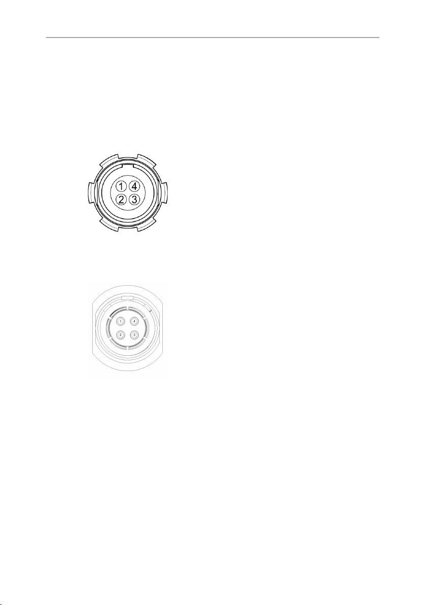
LBUS Connector
1 GND Ground
2 CAN-L CAN bus
3 V-BAT Power supply
in-/output
4 CAN-H CAN bus
SERIAL Connector
1 RX RXD (DTE) / B
2 VCC Power ouput
(6.5-35V)
3 TX TXD (DTE) / A
4 GND Ground
14.4 Environmental
Temperature range (operational): -20 to +50°C (-4° to +122° F)
14.5 Service Mode
The Hi-5 has a web interface offering control over most Hi-5
functions. It includes a service mode for testing buttons, LEDs
and sensors, as well as calibrating the sensors of the focus
knob, iris slider and Force-Pad. This particularly fixes a potential
Page 53

Appendix 53
non-linearity of the focus knob that can cause a misalignment
with pre-marked focus rings and hand-marked rings that are
exchanged between various Hi-5 units.
ADVICE
Do ONLY use the service mode if you experience issues and
need to re-calibrate the Hi-5 control elements! Make sure that
you understand the calibration procedure before using it.
To access the web interface, proceed as follows:
1. Connect Hi-5 and a computer via USB-C interface.
2. Open the web browser and enter the address hi-5-xxxxx.local,
with xxxxxx being the serial number of the Hi-5.
3. Enter user name: service
4. Enter password: access
To enter the service mode, proceed as follows:
1. Go to the Service tab.
2. Select Enable Service Mode.
3. Proceed with testing and calibration as per the displayed
instructions.
14.6 Service Contacts
Arnold & Richter Cine Technik
GmbH & Co. Betriebs KG
Herbert-Bayer-Str. 10
80807 Munich
Germany
+49 89 3809 2121
Business hours:
Mo. - Fr. 09:00 - 17:00 (CET)
service@arri.de
ARRI CT Limited / London
2 Highbridge, Oxford Road
UB8 1LX Uxbridge
United Kingdom
Vienna, Austria
ARRI Cine + Video Geräte
Ges.m.b.H.
+43 1 8920107 30
service@arri.at
Business hours:
Mo. - Fr. 09:00 - 17:00 (CET)
Milan, Italy
ARRI Italia S.r.l.
+39 (02)262 271 75
info@arri.it
Page 54

54 Appendix
+44 1895 457 000
Business hours:
Mo. - Thu. 09:00 - 17:30
Fr. 09:00 - 17:00 (GMT)
service@arri-ct.com
ARRI Inc. / West Coast
3700 Vanowen Street
CA 91505 Burbank
USA
+1 818 841 7070
Business hours:
Mo. - Fr. 09:00 am- 05:00 pm (PT)
service@arri.com
ARRI Canada Limited
1200 Aerowood Drive, Unit 29
ON L4W 2S7 Mississauga
Canada
+1 416 255 3335
Business hours:
Mo. - Fr. 08:30 am - 05:00 pm (EDT)
service@arri.com
ARRI China (Beijing) Co. Ltd.
Chaowai SOHO Tower C, 6/F,
0628/0656
Chaowai Dajie Yi 6
Beijing
China
+86 10 5900 9680
Business hours:
Mo. - Fr. 09:00 am - 06:00 pm (CST)
service@arri.cn
Business hours:
Mo. - Fr. 09:00 - 18:00 (CET)
ARRI Inc. / East Coast
617 Route 303
NY 10913 Blauvelt
USA
+1 845 353 1400
Business hours:
Mo. - Fr. 08:00 am - 05:30 pm (EST)
service@arri.com
ARRI Australia Pty Ltd
Level 1, Unit 1, 706 Mowbray Road
Lane Cove
NSW 2066 Sydney
Australia
+61 2 9855 43050
Business hours:
Mo. - Fr. 08:00 am - 05:00 pm
(AEST)
service@arri.com.au
ARRI ASIA Limited
41/F One Kowloon, 1 Wang
Yuen Street Kowloon Bay
Hong Kong
P. R. China
+852 2537 4266
Business hours:
Mo. - Fr. 10:00 am - 06:30 pm (HKT)
service@arri.cn
ARRI Brasil Ltda
Avenida Ibirapuera 2907 – Cj. 421,
Indianópolis
04029-200 São Paulo
Brazil
+55 1150419450
Business hours:
Mo. - Fr. 09:00 am - 05:30 pm (BRT)
arribrasil@arri.com
CINEOM Broadcast DMCC. CINEOM Broadcast India Pvt. Ltd.
Bars-Pro Ltd.
Distributor
4-Ya Magistralnaya Ulitsa, 11/2
123007 Moscow
Russia
+7 4995860299
Business hours:
Mo. - Sat. 10:00 - 18:00 (MSK)
arri@bars-pro.ru
C-4, Goldline Business Centre
Page 55

Appendix 55
Unit No. 2109, Jumeirah Bay Tower
X2 Cluster X
Jumeirah Lakes Towers
P.O Box 414659
Dubai, UAE
+971 (0) 45570477
Business hours:
Sa. - Th. 10:00 am- 06:00 pm
arriservice.me@cineom.com
LINKA Ithalat Ihracat ve Diş Tic.
Distributor
Halide Edip Adıvar Mah. Darülaceze
Cad.
No:3 Akın Plaza Kat:5 95-96
34381 Şişli, Istanbul
Turkey
+90 2123584520
Business hours:
Mo. - Fr. 09:00 - 18:00 (EET)
service@linkgroup.com.tr
Link Rd. Malad West
400 064 Mumbai
India
+91 (0)22 42 10 9000
Business hours:
Mo. - Sat. 10:00 am - 06:00 pm (IST)
arrisupportindia@cineom.com
Page 56

56 Appendix
14.7 Declarations of Conformity
14.7.1 International declarations
EU-Declaration of Conformity
The product conforms to the specifications of the following
European directives:
Directive 2014/30/EU of the European Parliament and
the Council of 26 February 2014 on the harmonisation of
the laws of the Member States relating to electromagnetic
compatibility
Directive 2011/65/EU of the European Parliament and
the Council of 8 June 2011 on the restriction of the use of
certain hazardous substances in electrical and electronic
equipment
The compliance with the requirements of the European Directives
was proved by the application of the following standards:
EN 55032:2015; EN 55035:2017;
EN 50581:2012
FCC Class A Statement
Note: This equipment has been tested and found to comply with
the limits for a Class A digital device, pursuant to Part 15 of the
FCC Rules. These limits are designed to provide reasonable
protection against harmful interference when the equipment
is operated in a commercial environment. This equipment
generates, uses, and can radiate radio frequency energy and, if
not installed and used in accordance with the instruction manual,
may cause harmful interference to radio communications.
Operation of this equipment in a residential area is likely to cause
harmful interference in which case the user will be required to
correct the interference at his own expense.
Page 57

Appendix 57
Caution: changes or modifications to the product not expressly
approved by the party responsible for compliance could void the
user's authority to operate the equipment.
Industry Canada Compliance Statement
CAN ICES-003(A)/NMB-003(A)
 Loading...