

Page 1

USER MANUAL
ALEXA Family of Cameras
Software Update Packet 10.0 (ALEXA XT/XR)
Software Update Packet 10.0 (ALEXA Classic)
Date: 22nd September 2014
Page 2

All rights reserved.
This document is provided under a license agreement containing
restrictions on use and disclosure and is also protected by copyright
law.
Due to continued product development this information may change
without notice. The information and intellectual property contained
herein is confidential between ARRI and the client and remains the
exclusive property of ARRI. If you find any problems in the
documentation, please report them to us in writing. ARRI does not
warrant that this document is error-free.
Arnold & Richter Cine Technik
Tuerkenstr. 89
D-80799 Munich
Germany
mailto: service@arri.com
http://www.arri.com
Page 3

III
Contents
1 Disclaimer 8
1.1 About This Manual ................................................................. 11
2 Scope 12
3 Introduction to the ALEXA 14
4 Layout of the ALEXA 22
5 Safety Guidelines 26
5.1 Explanation of Warning Signs and Indications ................... 26
5.2 General Safety Guidelines ..................................................... 26
5.3 Specific Safety Instructions ................................................... 27
6 General Precautions 29
6.1 Storage and Transport ........................................................... 29
6.2 Electromagnetic Interference ................................................ 29
6.3 Condensation .......................................................................... 29
7 Power Supply 31
7.1 Power Management ............................................................... 31
7.2 BAT Connector ....................................................................... 31
7.3 Mains Unit NG 12/26 R........................................................... 32
7.4 Cine-Style Batteries ................................................................ 32
7.5 Onboard Batteries .................................................................. 33
7.5.1 V-Lock Batteries ...................................................................... 33
7.5.2 Gold Mount Batteries ............................................................. 34
7.6 Power Outputs ........................................................................ 36
7.6.1 Powering 12 V Accessories ................................................... 36
7.6.2 Powering 24 V Accessories ................................................... 36
8 Camera Support 37
8.1 Minimum Equipment Recommended For Operation ......... 37
8.2 Tripod and Remote Heads ..................................................... 37
8.3 Electronic Viewfinder EVF-1 .................................................. 38
8.3.1 Viewfinder Cables .................................................................. 39
8.3.2 Viewfinder Mounting Bracket ............................................... 40
Page 4

IV Contents
8.4 Center Camera Handle CCH-1 ............................................... 42
8.5 Side Camera Handle SCH-1 ................................................... 43
8.6 Bridge Plates BP-12/BP-13 ..................................................... 44
8.7 Bridge Plate adapter BPA-1 ................................................... 45
8.8 Wedge Adapter WA-1 and Quick-Release Plate QR-HD-1 .. 46
8.9 Leveling Block LB-1 ................................................................ 46
8.10 Shoulder Pad SP-3 ................................................................. 47
9 Connectors 48
9.1 BAT .......................................................................................... 50
9.2 REC OUT 1 + 2 ........................................................................ 51
9.3 RET/SYNC IN ........................................................................... 51
9.4 MON OUT ............................................................................... 51
9.5 EXT .......................................................................................... 51
9.6 ETHERNET .............................................................................. 52
9.7 EVF ........................................................................................... 52
9.8 AUDIO IN ................................................................................. 52
9.9 RS ............................................................................................. 53
9.10 12 V .......................................................................................... 53
9.11 TC ............................................................................................. 53
9.12 AUDIO OUT ............................................................................. 53
9.13 SD Card ................................................................................... 54
9.14 SxS Slots ................................................................................. 55
9.15 XR (Xtended Recording) Module .......................................... 57
10 Lens Mounting 61
10.1 Lens Adapter PL Mount LA-PL-1 (no LDS) ........................... 61
10.2 Lens Support .......................................................................... 62
11 Camera Controls 64
11.1 Main Controls ......................................................................... 65
11.1.1 Display ..................................................................................... 65
11.1.2 Screen Buttons ....................................................................... 65
11.1.3 HOME screen .......................................................................... 66
11.1.3.1 Lists and User Lists ................................................................ 69
11.1.3.2 FPS ........................................................................................... 71
11.1.3.3 AUDIO...................................................................................... 76
11.1.3.4 SHUTTER ................................................................................ 79
11.1.3.5 EI .............................................................................................. 80
11.1.3.6 COLOR ..................................................................................... 81
Page 5

Contents V
11.1.3.7 WB ........................................................................................... 86
11.1.4 Function Buttons .................................................................... 88
11.1.4.1 TC ............................................................................................. 90
11.1.4.2 INFO ......................................................................................... 92
11.1.4.3 USER........................................................................................ 96
11.1.4.4 PLAY ........................................................................................ 99
11.1.5 Menu...................................................................................... 102
11.1.5.1 Recording .............................................................................. 103
11.1.5.2 Monitoring ............................................................................ 112
11.1.5.3 Project.................................................................................... 119
11.1.5.4 System................................................................................... 121
11.1.5.5 Frame grabs .......................................................................... 131
11.1.5.6 User Setups .......................................................................... 133
11.2 Operator controls ................................................................. 135
11.3 EVF-1 Controls ...................................................................... 136
11.3.1 Viewfinder EVF menu .......................................................... 136
11.3.2 Viewfinder CAM menu......................................................... 138
12 Operation of the Camera 139
12.1 Recording .............................................................................. 139
12.1.1 Internal recording ................................................................. 139
12.1.1.1 SxS Module .......................................................................... 139
12.1.1.2 XR Module ............................................................................ 140
12.1.1.3 Internal Recording Formats ................................................. 140
12.1.2 External recording ................................................................ 150
12.1.3 Parallel recording ................................................................. 152
12.1.4 High Speed recording .......................................................... 153
12.2 Monitoring ............................................................................ 153
12.2.1 Frame Lines .......................................................................... 154
12.2.2 Status Info Overlays ............................................................. 154
12.3 Using Timecode ................................................................... 156
12.4 Syncing the Sensors of Two Cameras ............................... 158
12.5 Syncing the Settings of Two Cameras ............................... 159
12.6 Sensor modes 16:9 and 4:3 ................................................. 161
13 ALEXA Plus 164
13.1 Lens Adapter PL-Mount LA-PL-2 (with LDS) ...................... 165
13.2 Radio System ........................................................................ 166
13.3 Wireless Remote System..................................................... 167
13.3.1 Lens Motors .......................................................................... 167
13.3.2 Hand Units ............................................................................ 169
Page 6

VI
Contents
13.4 Lens Data Display LDD-FP ................................................... 170
13.5 Plus Camera Controls .......................................................... 171
14 ALEXA Plus 4:3 177
15 ALEXA Studio 180
15.1 ALEXA Studio Images .......................................................... 181
15.2 Optics..................................................................................... 185
15.2.1 Electronic Mirror Shutter ..................................................... 186
15.2.2 Lens Adapter PL Mount LA-PL-2 (with LDS) ...................... 186
15.2.3 Optical Viewfinder ................................................................ 188
15.2.4 ND Filter ................................................................................ 196
15.3 Studio Camera Controls ...................................................... 197
15.4 4:3 Mode ............................................................................... 200
15.5 Licensed Features ................................................................. 202
16 ALEXA M 203
16.1 ALEXA M Images ................................................................. 204
16.2 ALEXA M Camera Head ....................................................... 209
16.2.1 CCH-2 ..................................................................................... 210
16.3 ALEXA M Camera Body ....................................................... 210
16.4 Fibre Connection .................................................................. 211
16.5 4:3 Mode ............................................................................... 213
16.6 Licensed Features ................................................................. 215
16.7 Lens Data System ................................................................. 215
17 ALEXA XT Cameras 216
17.1 In-Camera Filter Module IFM-1 ........................................... 217
17.1.1 Safety instructions for in-camera filtration ........................ 219
17.1.1.1 Maximum lens mounting depth ......................................... 219
17.1.1.2 Basic precautions ................................................................. 220
17.1.1.3 Required shimming and maximum lens mounting depth 221
17.1.1.4 Available IFM-1 and FSND Filter Sets ................................ 221
17.1.2 Preparing Internal Filtration ................................................ 221
17.1.2.1 FSND Filter Set (Basic) for ALEXA XT ................................ 222
17.1.2.2 IFM-1 Set for ALEXA Classic ............................................... 223
17.1.3 Shimming the lens mount ................................................... 226
17.1.4 Mounting in-camera filters .................................................. 233
17.1.5 Filter cleaning ....................................................................... 237
17.1.6 FSND Filter Set (Completion) .............................................. 238
17.1.7 FSND Filter Set (Full) for ALEXA XT ................................... 239
Page 7

Contents VII
17.2 Open Gate sensor mode ...................................................... 240
18 ALEXA Fiber Remote Option 241
19 Remote Control Unit RCU-4 242
20 Index 243
Appendix 247
A.1 Appendix ............................................................................... 248
A.2 Connector Pin Outs .............................................................. 253
A.3 False Color Display ............................................................... 259
A.4 Warning and Error Messages ............................................. 261
A.5 Dimensions, Weights and Menu Structure Trees ............. 270
Page 8

8 Disclaimer
1 Disclaimer
Before using the products described in this manual be sure to read and
understand all respective instruction.
The ARRI ALEXA is only available to commercial customers. The
customer grants by utilization that the ARRI ALEXA or other
components of the system are deployed for commercial use. Otherwise
the customer has the obligation to contact ARRI preceding the
utilization.
While ARRI endeavors to enhance the quality, reliability and safety of
their products, customers agree and acknowledge that the possibility of
defects thereof cannot be eliminated entirely. To minimize risk of
damage to property or injury (including death) to persons arising from
defects in the products, customers must incorporate sufficient safety
measures in their work with the system and have to heed the stated
canonic use.
ARRI or its subsidiaries do not assume any responsibility for incurred
losses due to improper handling or configuration of the camera or
other system components, due to sensor contamination, occurrence of
dead or defective pixels, defective signal connections or
incompatibilities with third party recording devices.
ARRI assumes no responsibility for any errors that may appear in this
document. The information is subject to change without notice.
For product specification changes since this manual was published,
refer to the latest publications of ARRI data sheets or data books, etc.,
for the most up-to-date specifications. Not all products and/or types are
available in every country. Please check with an ARRI sales
representative for availability and additional information.
Neither ARRI nor its subsidiaries assume any liability for infringement
of patents, copyrights or other intellectual property rights of third
parties by or arising from the use of ARRI products or any other liability
arising from the use of such products. No license, express, implied or
otherwise, is granted under any patents, copyrights or other intellectual
property right of ARRI or others.
ARRI or its subsidiaries expressly exclude any liability, warranty,
demand or other obligation for any claim, representation, or cause, or
action, or whatsoever, express or implied, whether in contract or tort,
including negligence, or incorporated in terms and conditions, whether
by statue, law or otherwise. In no event shall ARRI or its subsidiaries be
liable for or have a remedy for recovery of any special, direct, indirect,
incidental, or consequential damages, including, but not limited to lost
profits, lost savings, lost revenues or economic loss of any kind or for
any claim by third party, downtime, good-will, damage to or
replacement of equipment or property, any cost or recovering of any
material or goods associated with the assembly or use of our products,
or any other damages or injury of the persons and so on or under any
other legal theory.
In the case one or all of the foregoing clauses are not allowed by
applicable law, the fullest extent permissible clauses by applicable law
are validated.
Page 9

About This Manual 9
ARRI is a registered trademark of Arnold & Richter Cine Technik GmbH
& Co Betriebs KG.
Note: This product and the accessories recommended by the manufacturer
fulfill the specifications of the European Directive 2004/108/EC (15th December
2004).
The ALEXA viewfinder EVF-1 contains proprietary technology owned by
Fourth Dimension Displays Limited and licensed by ARRI.
This product contains licensed technology from Linotype.
Quicktime and Quicktime logo are trademarks or registered trademarks
of Apple Computer, Inc., used under license therefrom.
Apple ProRes 422 Proxy, Apple ProRes 422 LT, Apple ProRes 422, Apple
ProRes 422 HQ, Apple ProRes 4444, Apple ProRes 444 XQ, and the
ProRes logo are trademarks or registered trademarks of Apple
Computer, Inc., used under license therefrom.
SxS and
are trademarks of SONY corporation.
mkdosfs
Portions © 1998, Robert Nordier. All Rights Reserved.
© 1998, Robert Nordier. All rights reserved.
Redistribution and use in source and binary forms, with or without
modification, are permitted provided that the following conditions are
met:
Redistributions of source code must retain the above copyright notice,
this list of conditions and the following disclaimer.
Redistributions in binary form must reproduce the above copyright
notice, this list of conditions and the following disclaimer in the
documentation and/or other materials provided with the distribution.
THIS SOFTWARE IS PROVIDED BY THE AUTHOR(S) “AS IS” AND ANY
EXPRESS OR IMPLIED WARRANTIES, INCLUDING, BUT NOT LIMITED
TO, THE IMPLIED WARRANTIES OF MERCHANTABILITY AND FITNESS
FOR A PARTICULAR PURPOSE ARE DISCLAIMED. IN NO EVENT SHALL
THE AUTHOR(S) BE LIABLE FOR ANY DIRECT, INDIRECT, INCIDENTAL,
SPECIAL, EXEMPLARY, OR CONSEQUENTIAL DAMAGES (INCLUDING,
BUT NOT LIMITED TO, PROCUREMENT OF SUBSTITUTE GOODS OR
SERVICES; LOSS OF USE, DATA, OR PROFITS; OR BUSINESS
INTERRUPTION) HOWEVER CAUSED AND ON ANY THEORY OF
LIABILITY, WHETHER IN CONTRACT, STRICT LIABILITY, OR TORT
(INCLUDING NEGLIGENCE OR OTHERWISE) ARISING IN ANY WAY
OUT OF THE USE OF THIS SOFTWARE, EVEN IF ADVISED OF THE
POSSIBILITY OF SUCH DAMAGE.
This product meets CE regulations.
Page 10

10 Disclaimer
Page 11

About This Manual 11
1.1 About This Manual
ARRI recommends that all users of the ALEXA read the manual in its
entirety prior to use. For experienced users, the manual's structure also
provides quick access for reference.
In this manual:
• Layout of the ALEXA
• Safety Guidelines
• General Precautions
• Power Supply
• Camera Support
• Connectors
• Lens Mounting
• User Interface
• Operation of the ALEXA
How to Use This Manual
All directions are given from a camera operator's point of view. For
example, camera-right side refers to the right side of the camera when
standing behind the camera and operating it in a normal fashion.
Connectors are written in all capital letters, for example, REC OUT.
Menus and screens on the Main Camera Controls are written in all
capital letters, for example, RECORDING menu and HOME screen.
Buttons are written in bold typeface capital letters, for example, PLAY
button.
The appendix at the back of the manual contains useful reference
material including ALEXA specifications, connector pin-out diagrams, a
false color display explanation, error and warning message
explanations, ALEXA dimensional drawings and a menu structure tree.
Page 12

12 Scope
2 Scope
This instruction manual applies to the following hardware, software
and firmware versions:
ALEXA, ALEXA Plus, ALEXA Plus 4:3, ALEXA M: with Electronic
Viewfinder EVF-1;
ALEXA XT, ALEXA XT Plus, ALEXA XT M: with Electronic Viewfinder
EVF-1;
ALEXA Studio, ALEXA XT Studio: with optical viewfinder or with
Electronic Viewfinder EVF-1;
• Camera Software Update Packet (SUP) for ALEXA
XT cameras and ALEXA Classic cameras with XR
module upgrade:
• Camera Software Update Packet (SUP) for ALEXA
Classic cameras with SxS module:
10.0
10.0
Please note that ALEXA HD and ALEXA HD Plus cameras are limited to
SUP 7.0 and thus the SUP 7.0 manual should be used for those
cameras.
Document revision history
S
UP ID drawing release/
revision
2.1 K5.72550.0 2031-00-00-00-99 FG5445 29th Nov 2010
3.0 K5.72550.0 2031-00-00-00-99 K7741 11th Feb 2011
3.1 K5.72550.0 2031-00-00-00-99-B K7776 04th Apr 2011
3.1 K5.72550.0 2031-00-00-00-99-C K7781 07th Apr 2011
4.0 K5.72550.0 2031-00-00-00-99-D K7817 05th Jul 2011
4.0.1 K5.72550.0 2031-00-00-00-99-E K7845 24th Aug 2011
5.0 K5.72550.0 2031-00-00-00-99-F K7874 16th Nov 2011
5.0 +
5.1
K5.72550.0 2031-00-00-00-99-G K7890 19th Dec 2011
date
5.0 +
5.1
5.1 +
6.0
K5.72550.0 2031-00-00-00-99-H K8005 26th Jan 2011
K5.72550.0 2031-00-00-00-99-I K8021 12th Feb 2012
Page 13

About This Manual 13
SUP ID drawing release/
revision
6.1 K5.72550.0 2031-00-00-00-99-J K8071 14th May 2012
7.0 K5.72550.0 2031-00-00-00-99-K K8128 5th Nov 2012
7.0.1 K5.72550.0 2031-00-00-00-99-L K8169 14th Jan 2013
7.1 K5.72550.0 2031-00-00-00-99-M K8189 30th Jan 2013
8.0 K5.72550.0 2031-00-00-00-99-N K8223 22nd April 2013
8.0 K5.72550.0 2031-00-00-00-99-O K8257 18th June 2013
8.0 +
8.1
9.0
10.0
10000073 V01 K08304 17th July 2013
10000073 V02 K08340 25th Nov 2013
10000073 V03 K08576 22nd Sep 2014
date
Page 14

14 Introduction to the ALEXA
3 Introduction to the ALEXA
ARRI ALEXA is an extraordinary 35mm format digital camera system
designed for motion pictures and television, consisting of eleven
cameras and an extensive range of primes, zooms, accessories and
recording solutions. Combining innovative digital technology with 95
years of ARRI history and experience has created a camera system that
makes it easy to create great looking images.
• The ALEXA and ALEXA XT provide the most affordable entry
with full ALEXA image quality.
• ALEXA Plus adds support for the ARRI Wireless Remote System
(WRS), cmotion cvolution lens control, ARRI Lens Data System,
an additional HD-SDI and RS output and expanded metadata.
• ALEXA Plus 4:3 and ALEXA XT Plus share the same features as
the ALEXA Plus but with a taller usable sensor area (4:3) for
plug-and-play use with anamorphic lenses. Providing unmatched
versatility, the ALEXA Plus, ALEXA Plus 4:3 and ALEXA XT Plus
have become the workhorses of the industry.
• ALEXA M and ALEXA XT M are specialists; a modular system
with a separate camera head and body for action oriented
cinematography, aerial mounts and 3D.
• The flagships of the range, the ALEXA Studio and ALEXA XT
Studio, are the only digital motion picture cameras with an
optical viewfinder and a rotating mirror shutter.
• The ALEXA HD and ALEXA HD Plus form the basis of the ALEXA
Fiber Remote and ALEXA Fiber Remote camera sets. Since they
are designed for HD-only use, they do not include and cannot be
upgraded to ARRIRAW, ProRes 2K, DNxHD 444, 4:3, 3D sync or
the XR Module.
All ALEXA cameras offer exceptional image quality with the organic look
and feel of film; their unequalled exposure latitude, high sensitivity and
unique ARRI color processing provide sharp and natural images with a
cinematic look of breathtaking richness and detail.
Making them the perfect tools for a wide range of workflow and budget
requirements, ALEXA cameras allow for the most efficient and versatile
workflows. They can simultaneously output a number of formats, all
with audio and metadata. Their ability to record Apple ProRes (in HD or
2K*) or Avid DNxHD images to in-camera media offers file-based
workflows of unparalleled efficiency for immediate time and cost
savings. ARRIRAW* (in-camera with XT cameras and ALEXA Classic
cameras upgraded with the XR Module) delivers the pinnacle in image
quality, postproduction flexibility and archiving peace of mind, while
the HD-SDI outputs integrate seamlessly into existing HD
infrastructures.
Page 15

About This Manual 15
ALEXAs are true ARRI cameras: simple and safe to operate, ergonomic in
design and reliable in even the most extreme environments. ALEXA
cameras are designed around the way you work and, like all other ARRI
products, are backed by the global ARRI service network.
To provide more choices to the filmmaker, the ALEXA system is based
on an open architecture with many industry-standard interfaces and
compatibility with third party products. This, in combination with a
number of components on the camera that can be upgraded and long
product cycles make the system future-proof and ensures a safe return
on investment.
More than just hardware, ALEXA cameras represent an entire image
pipeline that stands alone as the most complete and powerful digital
production system ever built.
Exceptional Image Performance
• Film-like, organic look
• Wide exposure latitude
− 14+ stops over the entire EI range as measured with the ARRI
Dynamic Range Test Chart
− Extended, clean highlights
− Extremely low noise floor
− Future proof for High Dynamic Range (HDR) displays
• High sensitivity
− True base sensitivity of EI 800
− Adjustable from EI 160 to EI 3200
• ARRI color science
− Natural color reproduction, especially for skin tones
− Excellent color separation
− Holds up extremely well when over or underexposed
• Sharp, natural images for HD, 2K, UHD or 4K deliverables
Page 16

16 Introduction to the ALEXA
All ALEXA cameras provide the best looking digital image with the least
amount of fuss. This is made possible by a unique imaging chain
consisting of a high end optical low pass filter, a custom made CMOS
sensor with Dual Gain Architecture (DGA) and custom electronics and
processing software. These components are carefully crafted by ARRI
so that together they produce images with the organic look and feel of
film. The sensor provides unequalled exposure latitude of over 14 stops
over the entire EI range, with special consideration given to a gentle
highlight treatment. Creating a good looking roll-off in the highlights is
probably one of the most difficult tasks for any camera designer and we
have spent enormous resources at insuring ALEXA's outstanding
performance in the critical area between almost overexposed and fully
overexposed. ALEXA's high sensitivity and its ability to hold up very
well even when extremely under- or overexposed speed up work on
any real-world set. ALEXA's color processing was developed by our
own color scientists (who are the same people that have been working
on the ARRILASER and ARRISCAN, so are intimately familiar with both
film and digital color science), and creates clean and natural colors,
especially noticeable in ALEXA's great looking skin tones. The low
noise floor and great color separation helps greatly in color correction
and compositing. Our goal is creating the best looking images, and
when assessing imaging technologies, we always ask if it improves the
image, disregarding the marketing hype. With ALEXA we have, as the
visual effects supervisor of The Avengers put it, created "better pixels".
Efficient and Versatile Workflows
• Multiple in-camera recording options
1,2
− ARRIRAW
, ProRes or DNxHD
− Log C or Rec 709 gamma
− Optional ARRI Look Files for custom looks
− Embedded metadata in all file formats
• ARRIRAW1
− Uncompressed, unencrypted raw sensor data
− 16:9 or 4:3 resolutions
− Greatest image quality from ALEXA
− Greatest flexibility in post
− Best option for future-proof archiving
• Apple ProRes
− ProRes 422, 422 HQ, 4444 and 4444 XQ2
− HD or 2K resolutions, 16:9 or 4:3 aspect ratios1
− Pre-recording1
− Native Final Cut Pro X support
• DNxHD
− DNxHD 145, DNxHD 220x and DNxHD 4441
− MXF wrapped files (SMPTE standard compliant)
− Native Avid Media Composer support
• Two independent HD-SDI outputs
− Optional ARRI Look Files for custom looks
− Streaming metadata
− 180º image rotation for fast Steadicam low mode
Page 17

About This Manual 17
• Online tools and downloadable apps
1
ALEXA HD and HD Plus do not include and cannot be upgraded to
ARRIRAW, ProRes 2K, DNxHD 444, 4:3 sensor mode, 3D sync, prerecording or the XR Module.
2
Only ALEXA XT cameras and ALEXA Classic cameras with the XR
Module upgrade.
ALEXAs easily fit into many different types of projects because of the
versatility of their multiple outputs. ALEXAs can record and play back
Apple ProRes (in HD or 2K* resolution and 16:9 or 4:3 aspect ratio) or
DNxHD in-camera onto SxS PRO cards, CFast 2.0 cards or XR Capture
Drives, and ARRIRAW in 16:9, 4:3 or Open Gate aspect ratio onto XR
Capture Drives. Alternatively, uncompressed HD-SDI can be recorded
with an external recorder. Images can be recorded and/or output in Log
C or Rec 709, with optional ARRI Look Files for an accurate preview on
set and with a full set of rich metadata to streamline production. So
disregarding if you want to shoot a low budget TV series or Martin
Scorsese's next big Hollywood feature film, ALEXA can be easily
configured for the task at hand.
Simple and Safe Operation
• ARRI Product Quality
• Rugged and reliable
− Sealed electronics compartment
− Unique cooling system
− Stable lens mount/sensor holder
− Continuous file closing to protect footage
− Self-healing metadata
• Intuitive, easy to use controls
− Same interface on all ALEXA models
• High quality electronic viewfinder
• Powerful assistive displays, including
− Surround view
− False color exposure check
− Smooth mode for better motion portrayal
− Peaking focus check
− Compare stored image with live image
− RETURN IN video
• Well balanced, ergonomic body design
• Global ARRI service network
Page 18

18 Introduction to the ALEXA
ALEXA cameras are part of a long heritage of cameras from ARRI, and
we are very familiar with the sometimes horrid things done to our
cameras in the field. We just have to go into our own service
department to see the carnage! So ALEXAs are built rugged and
reliable with a sealed electronics compartment, a unique cooling
system and the most stable lens/sensor mount German engineering
could devise. All ALEXAs are backed by ARRI's global service network,
providing a friendly ARRI service technician accessible 24/5.
We know what it is like to try to change fps and shutter angle at 4:00 am
in the morning in the rain after a long night shoot. Professional
cameras need to be very simple to operate, and they need to make sure
that a good looking image is recorded, no matter what. With ALEXA we
have developed an intuitive user interface that is easy to learn and
quick to operate. The same interface is used on all models of ALEXA,
with the same menu, buttons, etc., so there is no learning curve when
using another model ALEXA.
Critically important to camera operators is the viewfinder. Based on our
experience with optical viewfinders, ALEXA's electronic viewfinder
provides an exceptionally clear image with natural skin tones and
smooth motion portrayal that is easy on the eye. For those who
appreciate the advantages of optical viewfinders, the ALEXA Studio can
be operated with an optical or electronic viewfinder. The electronic
viewfinder includes powerful assistive displays like surround view, false
color exposure check or anamorphic de-squeeze.
The hardware of the camera is designed for the best and most
ergonomic use on the set, including the built-in shoulder cut-out, many
attachment points on the camera's precision machined housing and a
large numbers of accessories like the low mode set, the Remote Control
Unit RCU-4 or the Wireless Compact Unit WCU-4. With meticulous
attention to detail we have added many small but helpful design
refinements, including built-in supports for 15 mm lightweight rods or
differently shaped extrusions (eyebrows) above some buttons so the
operator can feel the button's position even from the other side of the
camera or shooting in low light. The same care has been taken to
ensure compatibility with the extensive range of exiting accessories.
ALEXAs are well balanced and can be quickly switched from shoulder
use to tripod, crane or Steadicam. They accept a wide range of power
input from 10.5 to 34 V DC. Multiple power sources can be
simultaneously connected (with hot plug capability) and a smart circuit
will automatically switch to the one with the highest voltage.
Open, Future Proof Architecture
• Compatibility with industry standards
− PL mount lenses
− Apple ProRes, Avid DNxHD, HD-SDI, S
CFast 2.0 cards
− Gold mount or V-lock on-board batteries
− 12 or 24 V power inputs and outputs
xS PRO cards and
Page 19

About This Manual 19
− Support for ARRI and cmotion cvolution wireless lens control
systems
− ARRIRAW* support for third parties through ARRI Partner
Program and ARRIRAW SDK
• Numerous upgrade options
− Upgradable in-camera recording module (XR Module)
− Upgradable electronics interface module (Plus side panel)
− Exchangeable Lens Mount (ELM)
− Easy and powerful free Software Update Packets (SUPs)
− New features through purchase of license
• Long product cycles
We are open to equipment and standards from other manufacturers, be
that PL mount lenses, Apple ProRes, the HD-SDI standard, Gold or Vmount on-board batteries, cmotion lens control systems or both 12 and
24V accessory power outputs. We want to make sure that you can put
together the right ALEXA package with the accessories you want.
To ensure a smooth post production workflow, we are sharing our color
science with post production equipment manufacturers through the
ARRI Partner Program. Our ARRIRAW Software Development Kit (SDK)
allows them to integrate the ARRI debayering algorithm or create their
own, depending on what works best for them.
In addition, ALEXAs can be upgraded, as we have shown with the Plus
upgrade, the Fiber Remote Option, the XR Module upgrade and as we
are continuously showing with our free Software Upgrade Packets that
provide new and exciting features like ProRes 2K, ProRes 4:3, ProRes
4444 XQ, ARRIRAW Open Gate or 180º image rotation. Further features
like high speed or anamorphic de-squeeze are included in some
cameras and can be purchased through software licenses for the
others. All this, combined with our long product cycles, create a
sustainable business model for all owners of ARRI cameras.
ALEXA XT CAMERAS
Second generation ALEXAs are called ALEXA XT cameras (Xtended
Technology). They were released in 2013 and, in addition to all the
features of the ALEXA Classic camera, they are equipped with the XR
Module (Xtended Recording), internal ND filtration, a 4:3 Super 35
sensor, built-in CDL server and an LDS PL mount. In addition, they have
a new viewfinder mounting bracket, include anamorphic de-squeeze
and high speed licenses as well as a new, super silent fan. ALEXA XT
cameras are the ALEXA XT, ALEXA XT M, ALEXA XT Plus and ALEXA
XT Studio. The XR Module is on the left side of the camera. It has one
slot for either an XR Capture Drive, the SxS Adapter for use with SxS
PRO cards or the CFast 2.0 Adapter for use with CFast 2.0 cards.
• Faster, lighter and more affordable ARRIRAW recordin
− In-camera ARRIRAW recording up to 120 fps onto XR Capture
Drives
− Proven, efficient and versatile Codex ARRIRAW workfl
g
ow
Page 20

20 Introduction to the ALEXA
• Faster and longer ProRes/DNxHD in-camera recording
− ProRes or DNxHD onto SxS PRO cards with SxS Adapter or
CFast 2.0 cards with CFast 2.0 Adapter
− ProRes or DNxHD high speed onto XR Capture Drives or CFast
2.0 cards
− Proven, efficient and versatile ProRes/DNxHD workflow
• 4:3 Super 35 sensor
− Ideal for anamorphic lenses
− Increased post flexibility for spherical lenses
• Open Gate sensor mode
− Records full sensor area in ARRIRAW
− For image repositioning, resizing, rotating or stabilizing
− For VFX work or upscale to 4K
• Built-in ND filter option3
− Neutral color balance at all densities
− Anti-reflective multi-coating maintains high contrast
− Precision polishing preserves image sharpness
− Internal filter holder reduces weight, reflections and hassle
− 8 full-spectrum neutral density (FSND) filters available from
ND 0.3 to ND 2.4
• Built-in Lens Data System (LDS)
− More efficient workflow on-set and in post
− Lens Data Archive (LDA) for use with non-LDS lenses
• Integrated CDL capture
− Stores ASC Color Decision List (CDL) in ARRIRAW metadata
• Included anamorphic de-squeeze and high speed licenses
• Viewfinder Mounting Bracket VMB-3
− Improved operating comfort and flexibility
− Strong and rigid construction
− Special hard, low friction anodizing on all moving parts
− 15 mm lightweight rods hold viewfinder mount
− Built-in bubble level
• Super silent ALEXA XT fan
• Quick switch BNC connectors
− Can be exchanged without camera disassembly
3
Only for ALEXA XT, ALEXA XT M and ALEXA XT Plus. ALEXA XT
Studio has its own motorized ND filter solution.
ALEXA Classic Cameras with the XR Module Upgrade
The ALEXA XR Module (XR = Xtended Recording), which is built into all
ALEXA XT cameras, is also available as an affordable upgrade for all
ALEXA Classic cameras. The ALEXA XR Module is a new side panel
with exciting in-camera recording options, replacing the current SxS
Module. It allows ALEXA Classic camera owners to embrace the latest
advances in recording technologies without having to purchase a new
camera, exemplifying the concept of modular upgradeability that was
built into the ALEXA design from the very beginning.
Page 21

About This Manual 21
Please note that most other features of the XT cameras can also be
installed in ALEXA Classic cameras as individual upgrades, like the
built-in ND filter option, the Viewfinder Mounting Bracket VMB-3 or the
super silent XT fan. However, only true ALEXA XT cameras are capable
of ARRIRAW Open Gate mode, and ALEXA Classic cameras will retain
their native aspect ratio when upgraded. So a 16:9 ALEXA Classic will
remain a 16:9 camera after the XR Module upgrade.
* ProRes 2K/16:9 and ARRIRAW output are not available on ALEXA HD and
ALEXA HD Plus
Page 22
22 Layout of the ALEXA
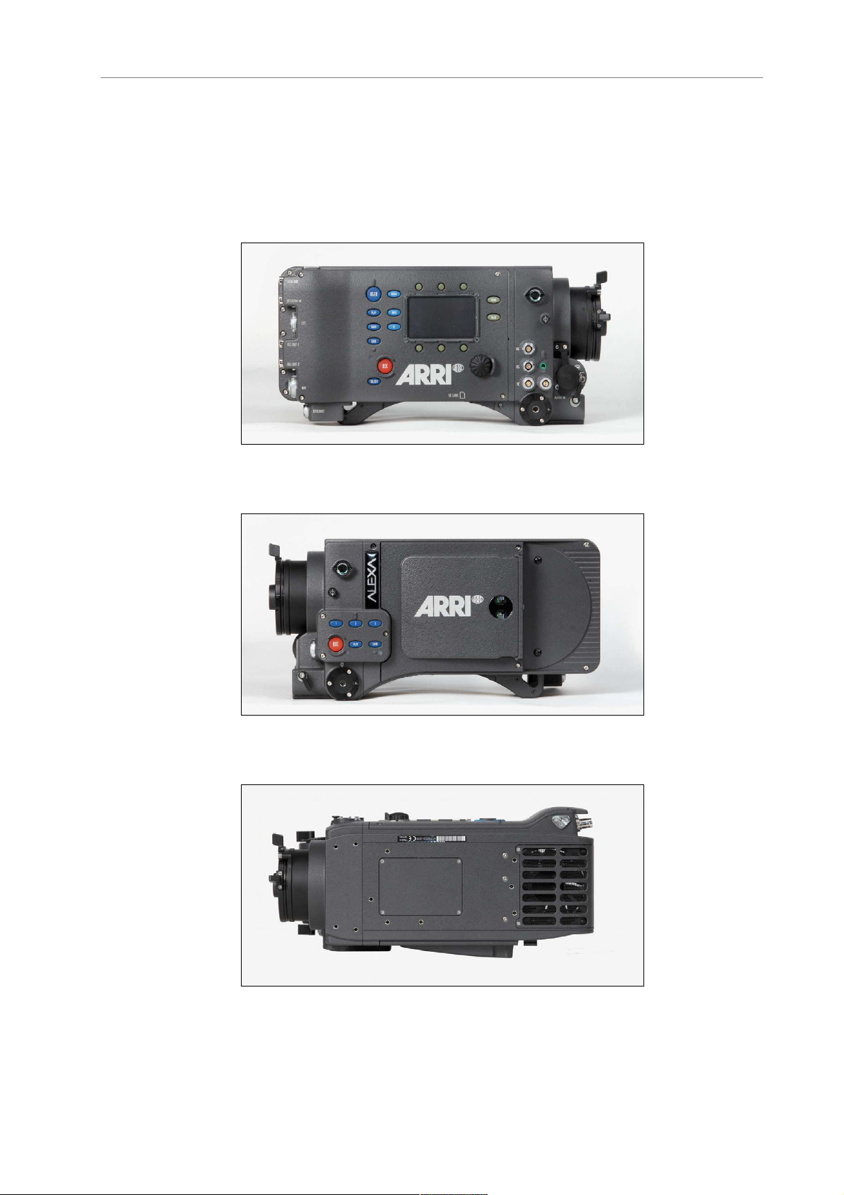
4 Layout of the ALEXA
The following images show the ALEXA Classic with SxS module:
Figure 1: ALEXA right
Figure 2: ALEXA left
Figure 3: ALEXA top
Page 23
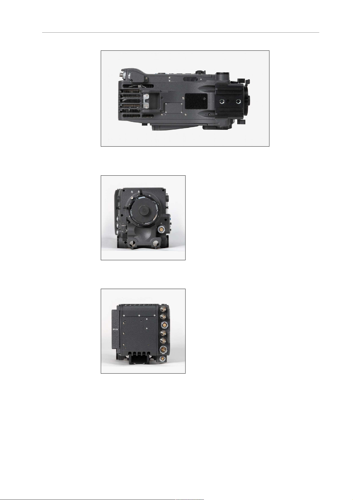
About This Manual 23
Figure 4: ALEXA bottom
Figure 5: ALEXA front
Figure 6: ALEXA back
Page 24
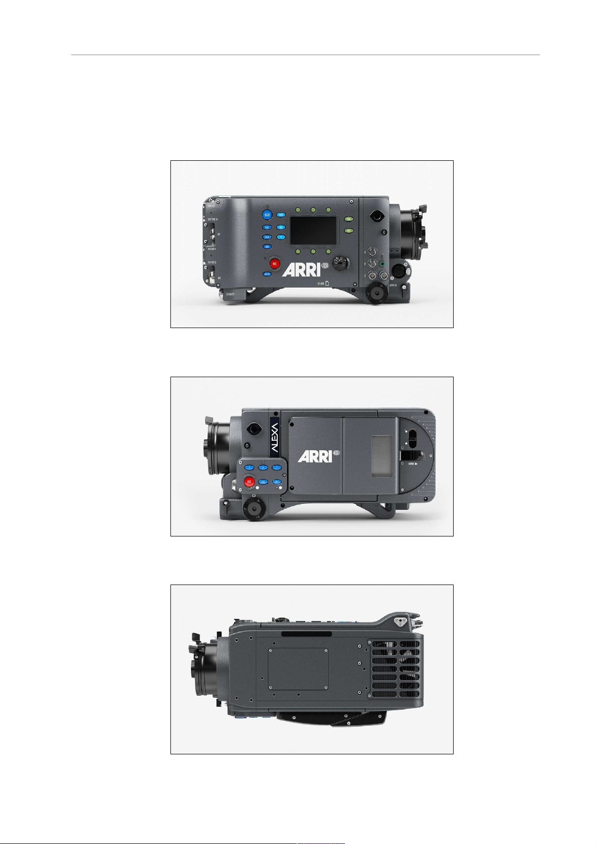
24 Layout of the ALEXA
The following images show the ALEXA Classic upgraded with the XR
module:
Figure 7: ALEXA right
Figure 8: ALEXA left
Page 25
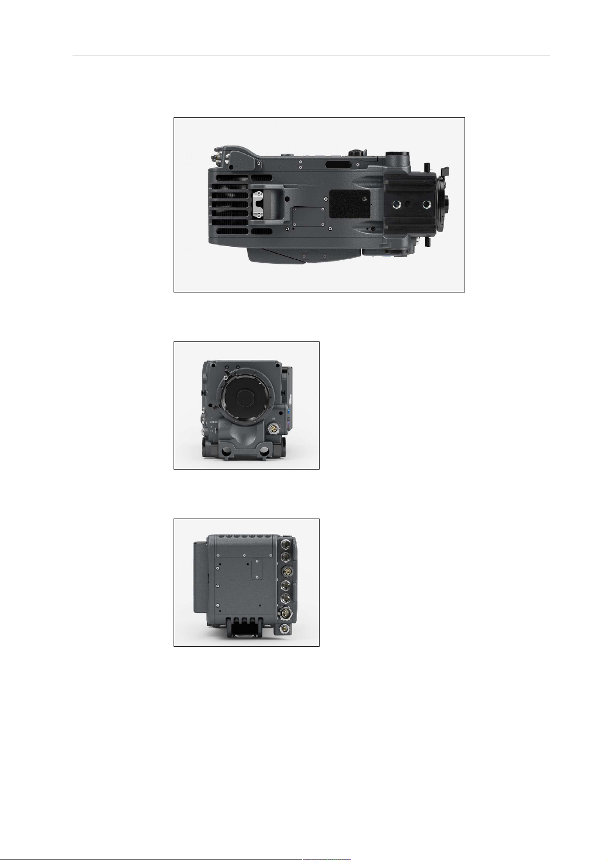
About This Manual 25
Figure 9: ALEXA top
Figure 10: ALEXA bottom
Figure 11: ALEXA front
Figure 12: ALEXA back
Page 26
26 Safety Guidelines
5 Safety Guidelines
Any violation of these safety instructions or non-observance of
personal care could cause serious injuries (including death) to users
and affiliates and damage to the equipment or other objects.
5.1 Explanation of Warning Signs and
Indications
Indicates a possible risk of injury or damage to the equipment
Indicates the risk of electric shock or fire danger that could
result in injury or damage to the equipment.
Note: Indicates further information or information from other instruction
manuals
5.2 General Safety Guidelines
• Always follow these guidelines to ensure against injury to
yourself or others and damage to the system or other objects.
• This safety information is in addition to the product specific
operating instructions in general and must be strictly observed
for safety reasons.
• Read and understand all safety and operating instructions before
you operate or install the system!
• Retain all safety and operating instructions for future reference.
• Heed all warnings on the system and in the safety and operating
instructions before you operate or install the system. Follow all
installation and operating instructions.
• Do not use accessories or attachments that are not
recommended by ARRI, as they may cause hazards and
invalidate the warranty!
• Do not attempt to repair any part of the system! Repairs must
only be carried out by authorized ARRI Service Centers.
Page 27

Specific Safety Instructions 27
5.3 Specific Safety Instructions
• Do not remove any safety measures from the system!
• Do not operate the system in areas with humidity above
operating levels or expose it to water or moisture!
• Do not cover the fan openings at the camera back top and
bottom!
• Do not subject the system to severe shocks!
• Do not place the system on an unstable trolley/hand truck, stand,
tripod, bracket, table or any other unstable support device! The
system may fall, causing serious personal injury and damage to
the system or other objects.
• Operate the system using only the type of power sour
indicated in the manual! Unplug the power cable by gripping the
power plug, not the cable!
• Never insert objects of any kind into any part of the system if not
clearly qualified for the task in the manual, as objects may touch
dangerous voltage points or short out parts! This could cause
fire or electrical shock.
• Unplug the system from the power outlet before opening any
part of the system or before making any changes to the system,
especially the attaching or removing of cables!
• Do not use solvents to clean!
• Do not remove any stickers or paint marked screws!
• Always place a lens or a protective cap in the lens mount
receptacle!
• Never run a camera with a mirror shutter without a lens or a
protective cap in the lens mount receptable!
• Changing camera lenses should be done in a dry and dust-free
environment. If this is not possible, take extra care that no dust
enters the camera while the lens is off!
• When no lens is attached to the camera, immediately place the
protective on the lens mount to avoid contamination of the
sensor cover glass!
• After changing lenses, always perform a dust check to make sure
no dust has settled on the sensor cover glass!
• Clean optical lens surfaces only with a lens brush or a clean lens
cloth. in cases of solid dirt or grease, moisten a lens cloth with
pure alcohol. Discard contaminated lens cloth after use! Never
attempt to clean a lens brush with your fingers!
• NEVER USE CANS WITH COMPRESSED AIR OR GAS TO BLOW
OFF THE DUST! This can severely damage optical elements.
ce
Page 28

28 Safety Guidelines
• If the sensor cover glass has been contaminated by solid dirt or
grease, special optical cleaning kits should be used for dirt
removal under very high care! If the contamination cannot be
removed, the camera should be taken to an ARRI service center
for cleaning.
• THE USE OF METHANOL TO CLEAN OPTICAL SURFACES IS
NOT RECOMMENDED!
• NEVER USE ACETONE TO CLEAN OPTICAL SURFACES!
• NEVER TRY TO REMOVE THE SENSOR COVER GLASS!
• DO NOT POINT THE CAMERA INTO DIRECT SUNLIGHT, VERY
BRIGHT LIGHT SOURCES, OR HIGH-ENERGY LIGHT SOURCES
(e.g. laser beams)! This may cause permanent damage to the
camera image sensor.
• DO NOT POINT THE VIEWFINDER INTO DIRECT SUNLIGHT,
VERY BRIGHT LIGHT SOURCES, OR HIGH-ENERGY LIGHT
SOURCES (e.g. laser beams)! This may cause permanent
damage to the viewfinder display and optical elements.
Page 29

Storage and Transport 29
6 General Precautions
6.1 Storage and Transport
• Use a lens port cap to prevent damage to the sensor cover glass
and sensor whenever there is no lens attached.
• Unplug all cables when transporting the ALEXA in a camera
case.
• Do not store the camera in places where it may be subject to
temperature extremes, direct sunlight, high humidity, severe
vibration, or strong magnetic fields.
6.2 Electromagnetic Interference
ALEXA meets EC regulations by fulfilling the specifications of the
European Directive 2004/108/EC (15th December 2004).
This equipment has been tested and found to comply with the limits for
a Class A digital device, pursuant to part 15 of the FCC Rules. These
limits are designed to provide reasonable protection against harmful
interference when the equipment is operated in a commercial
environment. This equipment generates, uses, and can radiate radio
frequency energy and, if not installed and used in accordance with the
instruction manual, may cause harmful interference to radio
communications. Operation of this equipment in a residential area is
likely to cause harmful interference in which case the user will be
required to correct the interference at his own expense.
Changes or modifications not expressly approved by the party
responsible for compliance could void the user's authority to operate
the equipment.
Complies with the canadian ICES-003 Class A specifications. Cet
appareil numérique de la Classe A est conformé à la norme NMB-003
du Canada.
This device complies with RSS 210 of Industry Canada. This Class A
device meets all the requirements of the Canadian interference-causing
equipment regulation. Cet appareil numérique de la Class A respecte
toutes les exigences du Réglement sur le matérial brouilleur du Canada.
6.3 Condensation
Page 30

30 General Precautions
When moving the camera from a cool to a warm location or when the
camera is used in a damp environment, condensation may form inside
the lens port, on the sensor cover glass, between the sensor and the
sensor cover glass, and on internal or external electrical connections.
• Operating the camera while condensation is present may result
in personal injury or damage to the equipment.
Condensation on the optical components may have a visible effect on
the output images. To reduce the risk of condensation:
• Find a warmer storage location.
• Attach the ARRI air-drying cartridge (silica bottle) to the PL-
Mount of the camera during storage
• Note: Do NOT leave the air-drying cartridge attached to the PL-
Mount during transportation of the camera!
• If camera needs to be stored in a place that is considerably
cooler than the location where it will be used, consider keeping
the camera powered from a mains unit in addition to using the
air-drying cartridge.
• In ambient temperatures above 30°C/86°F and/or humidity above
60%, always attach the air-drying cartridge to the PL-Mount of
the camera when not in use. This not only applies to storage, but
also to shooting breaks and situations when the camera remains
without an attached lens for an extended time.
• MAKE SURE THE SILICA BOTTLE IS SECURELY FASTENED.
UNDER NO CIRCUMSTANCES SPILL SILICA INTO THE LENS
PORT!
Page 31

Power Management 31
7 Power Supply
• Use only ARRI-recommended power supply solutions.
• Manipulation of power supplies could result in serious injury or
death, or damage to the ALEXA.
The ALEXA accepts an input voltage range from 10.5 to 34 V DC. The
camera can be powered through the BAT connector or battery adapters
accepting V-Lock or Gold Mount batteries.
The power supply should deliver an output of more than 90 W to power
the camera sufficiently. The power draw of the camera in basic
configuration is about 85 W.
A 12 to 15 V battery should have at least 6 A maximum output current.
Note: when powering accessories through the camera, the total power draw of
the camera is increased by the amount of power drawn by the accessories.
7.1 Power Management
When using the BAT connector and one or more onboard battery
adapters simultaneously, the camera’s power management system
ensures that the power source with the highest voltage level is used.
When the voltage level of one power source drops below the level of
the other, or a power source is disconnected from the camera, the
power management system automatically switches to the other power
source, avoiding shutdown of the camera.
For example, a 12 V onboard battery can be used as backup for the
main 24 V battery. Using a 12 V onboard battery in addition to the main
24 V battery also allows for quick switchover to handheld mode—the
power cable can simply be disconnected from the BAT connector.
When using two onboard battery adapters (with batteries in parallel—
one on top and one on the back), the camera will treat them as a single
source. When used this way, the load is spread across two batteries,
creating a strong power source.
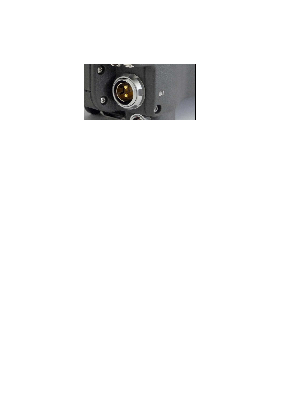
7.2 BAT Connector
The BAT connector is the primary power input on the ALEXA. It is a
Fischer 2-pin socket located at the back of the camera on the cameraright side.
Page 32
32 Power Supply
The socket accepts power cables KC-20S and KC-29S. The cables can
either be connected to the mains unit NG 12/26R or to 24 V cine-style
batteries with three-pin XLR outputs.
Figure 13: BAT connector
7.3 Mains Unit NG 12/26 R
Use of the mains unit is recommended for shooting in the studio and
when using electronic accessories with high power consumption.
To power the ALEXA using the Mains Unit NG 12/26 R:
1. Set the correct mains voltage on the mains unit using the fuse on
the back of the unit. For example, set it to 220 V if the AC mains
power source is 220 V.
2. Connect the mains unit to AC mains power.
3. Ensure that the camera power is turned off.
4. Set the voltage switch on the mains unit to 26 V.
5. Connect the battery cable KC-20S or KC-29S (spiral cable) to the
power supply socket on the camera and the 26 V socket on the
mains unit.
Note: The NG 12/24 R was the original design that provided 12 & 24 volts
output – it was superseded by the NG 12/26 R, which outputs 12 & 26 volts. The
NG 12/24 R can easily be upgraded to NG 12/26 R specification at an ARRI
service center.
7.4 Cine-Style Batteries
Any 24 V cine-style battery with a three-pin XLR output can be used to
power the camera through a KC-20S or a KC-29S battery cable.
To connect the battery to the camera:
nsure that the main switch on the camera is off.
1. E
Page 33

Onboard Batteries 33
2. Connect the battery cable KC-20S or KC-29S (spiral cable) to the
power supply socket on the camera and the 28V output on the
battery.
Note: When the battery voltage drops below the warning level, the BAT1 level
in the camera display will start flashing. A white i will appear, signaling more
information is available on the INFO screen. For more information on setting
the low battery warning level, see Menu>System>Power (on page 124).
7.5 Onboard Batteries
The camera can be equipped with adapters for either V-Lock or Gold
Mount video-style batteries. When a battery equipped with the TIprotocol for battery communication is used, the ALEXA will display
remaining capacity as a percentage on the Home screen. For these
batteries, the user does not need to set the battery warning level.
Four different adapters are available:
• BAB-G: Battery Adapter Back for Gold Mount batteries
• BAB-V: Battery Adapter Back for V-Lock batteries
• BAT-G: Battery Adapter Top for Gold Mount batteries
• BAT-V: Battery Adapter Top for V-Lock batteries
Note: Adapters must be installed by a trained technician!
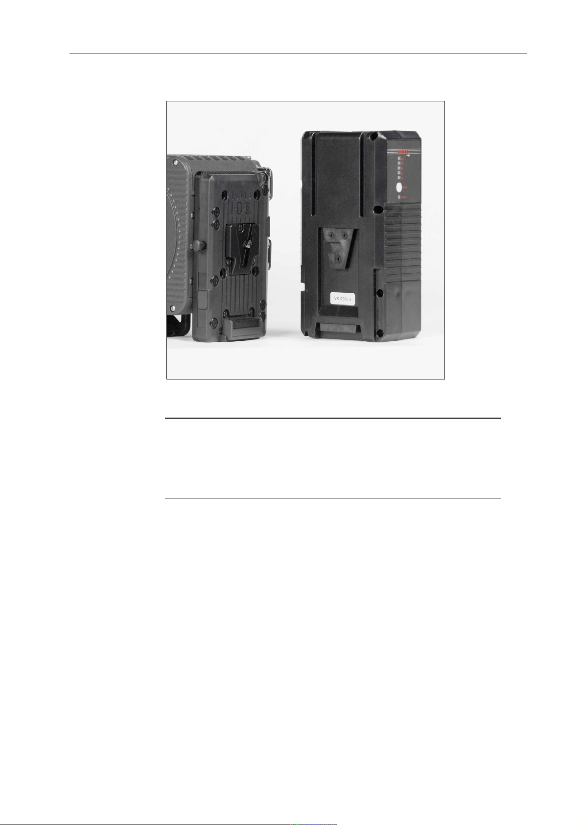
7.5.1 V-Lock Batteries
V-Lock batteries from different manufacturers may be used on the
ALEXA. When batteries from manufacturers such as ID-X and Bebop,
are used, their remaining capacity will be displayed as a percentage on
the Home screen.
To attach a V-Lock battery:
lign the v-shaped wedge on the battery with the v-shaped notch
1. A
on the battery plate.
2. Press the battery downwards until you hear a click.
3. Check that the battery is securely mounted on the battery plate.
To release a V-Lock battery:
1. Press the release button on the camera-left side or top of the battery
(manufacturer dependent).
Page 34
34 Power Supply
2. While pressing the release button, slide the battery upwards.
Figure 14: ALEXA with BAB-V and V-Mount battery
Note: Not all V-Lock batteries deliver enough power to supply the camera. Use
only batteries with a capacity of 90 Wh or more to prevent damage to the
battery and unpredictable camera behavior. Any camera-battery combination
should be tested prior to use, especially when accessories are powered through
the camera.
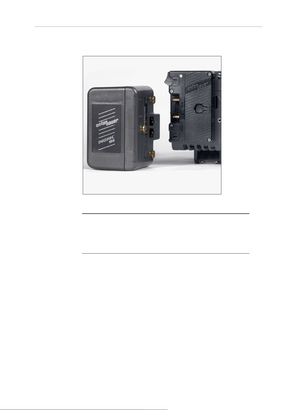
7.5.2 Gold Mount Batteries
If the ALEXA is equipped with a Gold Mount, Anton/Bauer batteries can
be used. Their remaining capacity will be displayed as a percentage on
the Home screen.
To attach a Gold Mount battery:
1. Align the three pins on the back of the battery to the three
corresponding holes on the battery plate.
2. Press the battery to camera-right until you hear a click.
3. Check that the battery is securely mounted on the battery plate.
To release a Gold Mount battery:
1. Press the release button on the camera-left side of the battery plate.
Page 35
Onboard Batteries 35
2. While pressing the release button, slide the battery camera-left, and
pull it straight out.
Figure 15: ALEXA with BAB-G and a Gold Mount battery
Note: Not all Gold Mount batteries deliver enough power to supply the camera.
Use only batteries with a capacity of 90 Wh or more to prevent damage to the
battery and unpredictable camera behavior. Any camera-battery combination
should be tested prior to use, especially when accessories are powered through
the camera.
Page 36
36 Power Supply
7.6 Power Outputs
The ALEXA, ALEXA M, ALEXA XT, ALEXA HD and ALEXA XT M have
two 24 V power outputs and one 12 V power output for accessories.
ALEXA Plus, ALEXA Plus 4:3, ALEXA HD Plus, ALEXA XT Plus, ALEXA
Studio and ALEXA XT Studio models have three 24 V power outputs
and one 12V power output.
Figure 16: 24 V outputs (RS) and 12 V output
7.6.1 Powering 12 V Accessories
One 12 V output with a 2-pin LEMO connector is located on the right
side of the camera. It is limited to 12 V and can supply a device with a
current of up to 2.2 A, depending on the camera power supply.
7.6.2 Powering 24 V Accessories
Two 24 V remote start/stop (RS) outputs with 3-pin Fischer connectors
are located on the right side of the camera. They can supply two
devices with a combined load of up to 2.2 A (shared with the EXT
connector power out), depending on the camera power supply. When
the camera is powered from a source with a voltage below 24 V, they
output 24 V. If the camera's power source supplies more than 24 V, this
voltage level is also present on the RS outputs.
Besides powering accessories, the RS outputs can also be used to send
a remote start/stop signal to the camera.
Page 37

Minimum Equipment Recommended For Operation 37
8 Camera Support
8.1 Minimum Equipment
Recommended For Operation
• ARRI ALEXA camera body including SxS module or XR module
and Lens Adapter PL mount without LDS (LA-PL-1)
• Electronic Viewfinder EVF-1
• Viewfinder Mounting Bracket
• KC 150-S Viewfinder Cable short 0.35m/1.2ft
• CCH-1 Center Camera Handle
• BP-12 Bridge Plate with base plate, or BPA-1 with BP
Bridge Plate and base plate, or WA-1 Wedge Adapter and Quick
Release HD Baseplate
• SD card
• Compatible power supply
• Suitable media for recording
-5/BP-8
8.2 Tripod and Remote Heads
Tripod and remote heads must have adequate load ratings to support
the ALEXA and attached accessories. See the following table for
camera and component weights.
Note: Always check the payload limits of a remote head and crane before
mounting a camera.
In applications where the camera mount is subject to high forces (e.g.
car or helicopter mounts) the camera must be additionally secured with
appropriate safety restraints. All mount screws must be tightened
firmly with an appropriate screwdriver (not with the commonly used
coin!).
Camera weight lb kg
ALEXA camera body weight with S
ALEXA camera setup weight with SxS module
(incl. EVF-1, VMB-1, CCH-1, KC-150S)
xS module
13.8 6.3
16.9 7.7
ALEXA camera body weight with XR module 14.5 6.6
Page 38

38 Camera Support
ALEXA camera setup weight with XR module
(incl. EVF-1, VMB-1, CCH-1, KC-150S)
17.6 8.0
8.3 Electronic Viewfinder EVF-1
The electronic viewfinder EVF-1 employs a liquid crystal on silicon
(LCOS) imaging device with a temperature-stabilized LED light source
to provide a bright, accurate view of the sensor image in all operating
conditions. Each EVF-1 is calibrated to precisely match the image on the
ALEXA's HD outputs.
The EVF-1 has a resolution of 1280x720 pixels, with 32 additional lines
of resolution above and 32 below the image to display camera status
information. The EVF-1 can also display a 10% surround view area of
the sensor to help the operator track unwanted elements before they
enter the recorded image area. Focus can be checked by temporarily
zooming into the image with a magnification factor of 2.25x. The lowlatency interface of the EVF-1 has a delay of less than 1 frame.
The EVF-1 has button controls for false color check and zoom, as well
as buttons and a jogwheel to control EVF and camera settings.
Page 39
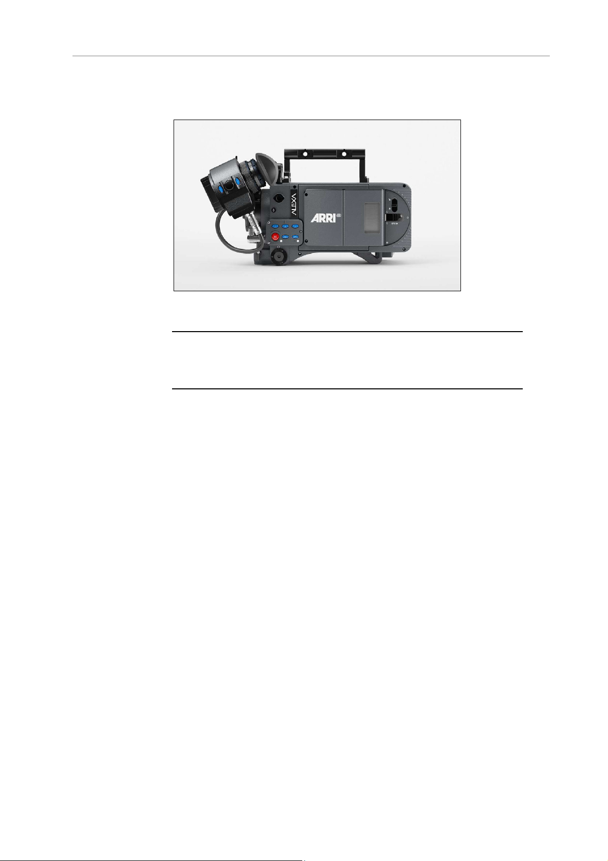
Electronic Viewfinder EVF-1 39
Connect the viewfinder to the camera using the viewfinder mounting
bracket.
Figure 17: ALEXA with XR module and EVF-1
Note: Do not point the viewfinder eyepiece at direct sunlight or bright light
sources, as this could damage the LCOS imaging device. If possible, cover the
eyepiece when not in use to prevent any damage.
8.3.1 Viewfinder Cables
The viewfinder cables are unidirectional with a male plug to connect to
the camera and a female plug to connect to the viewfinder.
Cables are available in the following lengths:
Model Length
(m / ft)
KC-150-S 0.35 / 1.2 For use of EVF-1 on camera left side in
KC-151-S 0.65 / 2.1 For use of EVF-1 on camera right side or
KC-152-S 2.00 / 6.6 Longest possible length for use with
Suggested use
handheld mode
when using Viewfinder Extension Bracket
VEB-1 or VEB-3
specialty rigs
Page 40
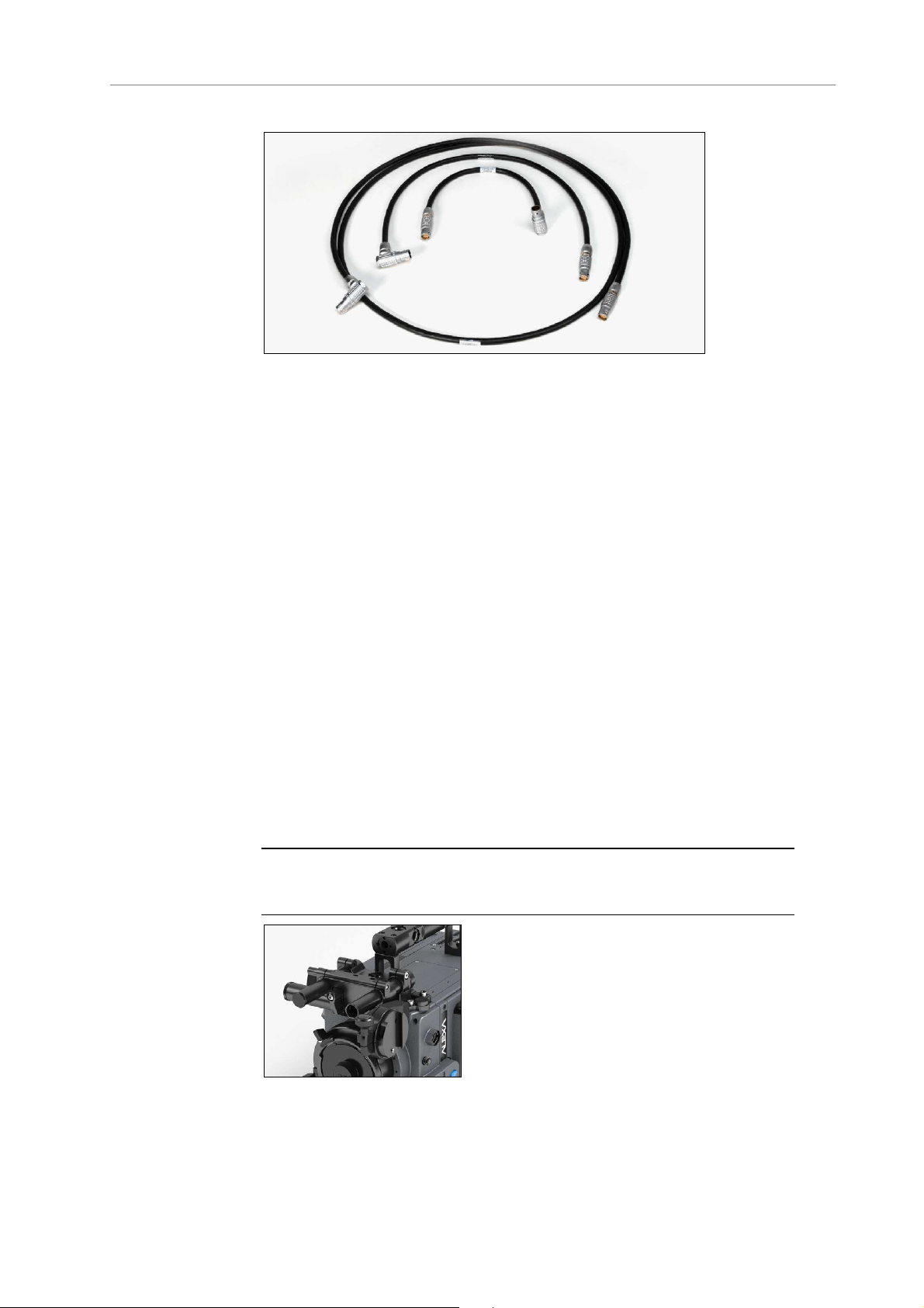
40 Camera Support
Figure 18: EVF cables: KC-150S (center), KC-151S (middle), KC-152S
(outer)
8.3.2 Viewfinder Mounting Bracket
The Viewfinder Mounting Bracket VMB-3 is attached to the camera
using two captive 3mm hex socket head screws on top of the camera at
the front. The VMB-3 features a leveling bubble and two internally
threaded 15mm rods with standard 60mm distance. These can be
exchanged for or extended with standard 15mm rods for mounting
matte boxes, lens motors and the like above the lens if need be.
Attach the EVF-1 to the Viewfinder Mounting Bracket by sliding the
dove tail into the receptacle and closing the lever on the EVF-1.
The position of the EVF-1 can be adjusted by loosening the levers on
the Viewfinder Mounting Bracket, adjusting the position as desired and
closing the levers to retighten.
The EVF-1 can be mounted on the camera-right side by unscrewing the
threaded end cap on the side-to-side adjustment rod, removing the rod
itself and inserting it from the other side. Remember to reattach the
threaded end cap.
Note: Camera-right operation is not possible with the standard EVF cable KC150-S. Instead, the longer cable KC-151-S is needed.
Figure 19: VMB-3 on camera
Page 41
Electronic Viewfinder EVF-1 41
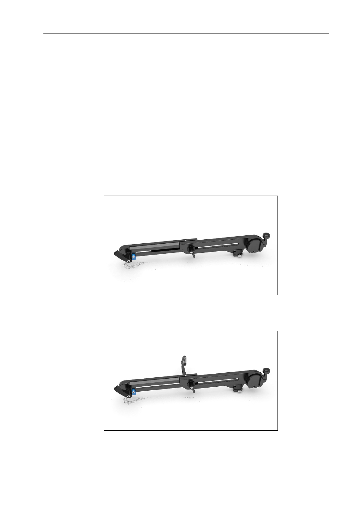
The Viewfinder Extension Bracket VEB-3 extends the mounting point of
the EVF-1 further back. It can be attached to a tripod head for use with
geared heads or greater comfort when using fluid heads using its
standard attachment point for the ARRI Eyepiece Leveler EL-3. The VEB3 has been improved over the VEB-1 in the following aspects:
• The redesigned shape provides greater sturdiness at a lighter
weight.
• The blue security pin at the VMB-3 connecting end prevents the
VEB-3 from accidently dropping out when it is released.
• The connection part to the Eyepiece Leveler EL-3 is spring
loaded so that it automatically moves away from the camera
body when it is not in use.
• The VEB-3 features a fold-out arm that can be used to rest the
VEB-3 on the camera body when moving the camera.
To avoid damage to the VMB-3 when using the VEB-3 with an eyepiece
leveler, loosen the friction on VMB-3’s rotating assembly.
Figure 20: VEB-3 with closed fold-out arm
Figure 21: VEB-3 with opened fold-out arm
Page 42

42 Camera Support
Figure 22: ALEXA with EVF-1, VEB-3 and cable KC-151S
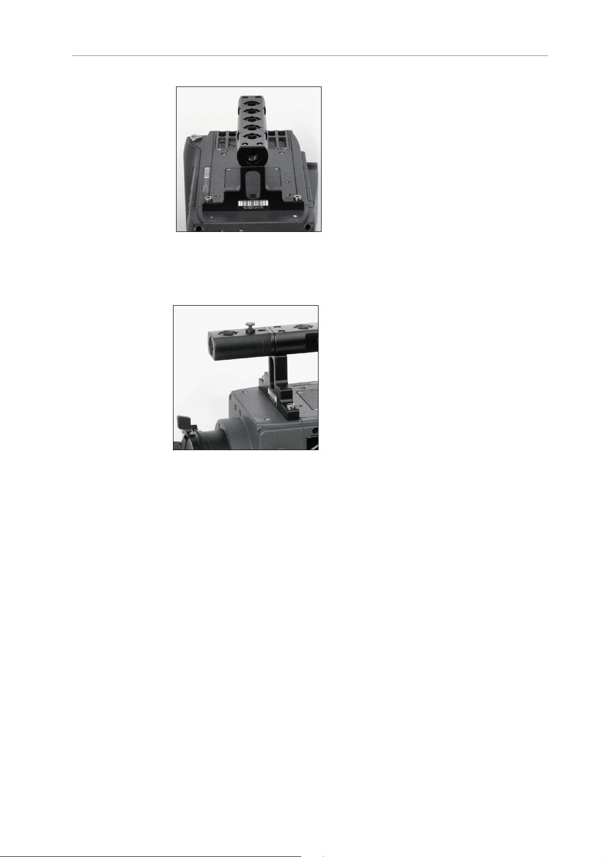
8.4 Center Camera Handle CCH-1
The Center Camera Handle CCH-1 is attached to the camera top with
three captive 3mm hex socket head screws (two at the front and one at
the back). Ensure that the CCH-1 is securely fastened before attempting
to lift the camera from it.
Figure 23: Camera with CCH-1, side view
Page 43
Side Camera Handle SCH-1 43
The Handle Extension Block HEB-2 mounts to the front end of the CCH1 and adds one more focus hook to the camera in a high position,
allowing the tape measure to clear the matte box.
8.5 Side Camera Handle SCH-1
The Side Camera Handle SCH-1 is used in conjunction with a BAT-V or
BAT-G top-mounting battery adapter, or with third-party onboard
recorders. It is attached to the camera using three captive 3mm hex
socket head screws (two at the front and one at the back). Ensure that
the SCH-1 is securely fastened before attempting to lift the camera from
it.
If a tall battery or a tall third-party onboard recorder is used, the
adjustable center grip of the SCH-1 can be replaced by the taller
Adjustable Center Grip Tall (ACG-2).
Page 44

44 Camera Support
Figure 24: SCH-1
Figure 25: Camera with SCH-1, side view
8.6 Bridge Plates BP-12/BP-13
The bridge plate BP-12 for 19 mm studio rods has been specifically
developed for ALEXA. It mounts directly to the camera body using two
3/8"/16 screws and ensures that support rods, matte boxes and follow
focus units are positioned properly in regards to the optical center of
the camera, just like all other ARRI cameras.
Page 45

Bridge Plate adapter BPA-1 45
The bridge plate BP-13 is equivalent to the BP-12, but for 15 mm studio
rods.
Note: Make sure bridge plates are tightened firmly with a wide bladed
screwdriver, not the commonly used coin!
8.7 Bridge Plate adapter BPA-1
The bridge plate adapter BPA-1 can be used to attach a BP-3/BP-5/BP8/BP-9 to ALEXA. First attach the BPA-1 to the camera with the two
screws. Then attach the bridge plate to the adaptor with its two screws.
Make sure the screws are tightened firmly with a screwdriver.
Page 46

46 Camera Support
8.8 Wedge Adapter WA-1 and QuickRelease Plate QR-HD-1
The WA-1 can be mounted at the same position as a bridge plate. It has
a dove tail that slides into the counter part of a quick-release plate, like
the ARRI QR-HD-1. The quick-release plate has a pin at its back, which
fits into the pin receptacle at the back of the camera base.
Figure 26: ARRI QR-HD-1
8.9 Leveling Block LB-1
The Leveling Block LB-1 attaches to the bottom of the ALEXA in the pin
receptacle on the back foot. It prevents the camera from resting on a
rear-mounted battery when a bridge plate is attached and the camera is
placed on a flat surface.
Attach the LB-1 by inserting its pin into the pin receptacle at the end of
the shoulder arc in the camera base. Twist the knob clockwise to
tighten.
Figure 27: Leveling Block LB-1
Page 47

Shoulder Pad SP-3 47
8.10 Shoulder Pad SP-3
The camera base has an integrated arch to fit to the operator's
shoulder. For extended handheld shots, the shoulder pad SP-3 can be
attached to the base of the camera with velcro.
Note: The SP-3 can only be used with a BP-12 and 19 mm rods or with 15 mm
rods and a Wedge Adapter WA-1 and a Quick-Release Plate QR-HD-1 . When
using the BPA-1 with a BP-5/BP-8, the bridge plate has to be removed prior to
attaching the SP-3.
Figure 28: SP-3 shoulder pad
Figure 29: SP-3 below camera
Page 48
48 Connectors
9 Connectors
Camera back
Figure 30: Connectors at back
From top to bottom: MON OUT, RET/SYNC IN, EXT, REC OUT 1, REC
OUT 2, BAT, ETHERNET
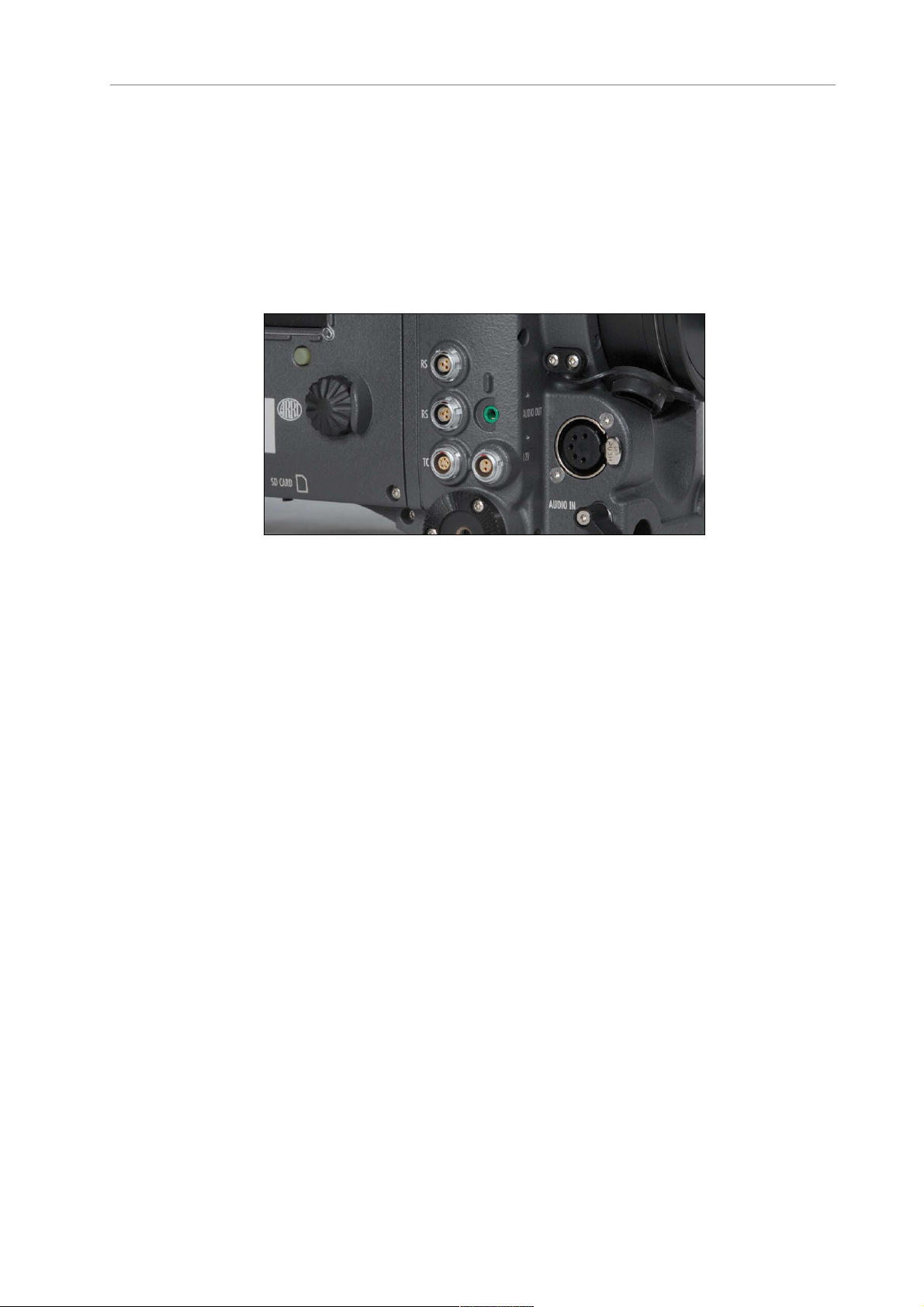
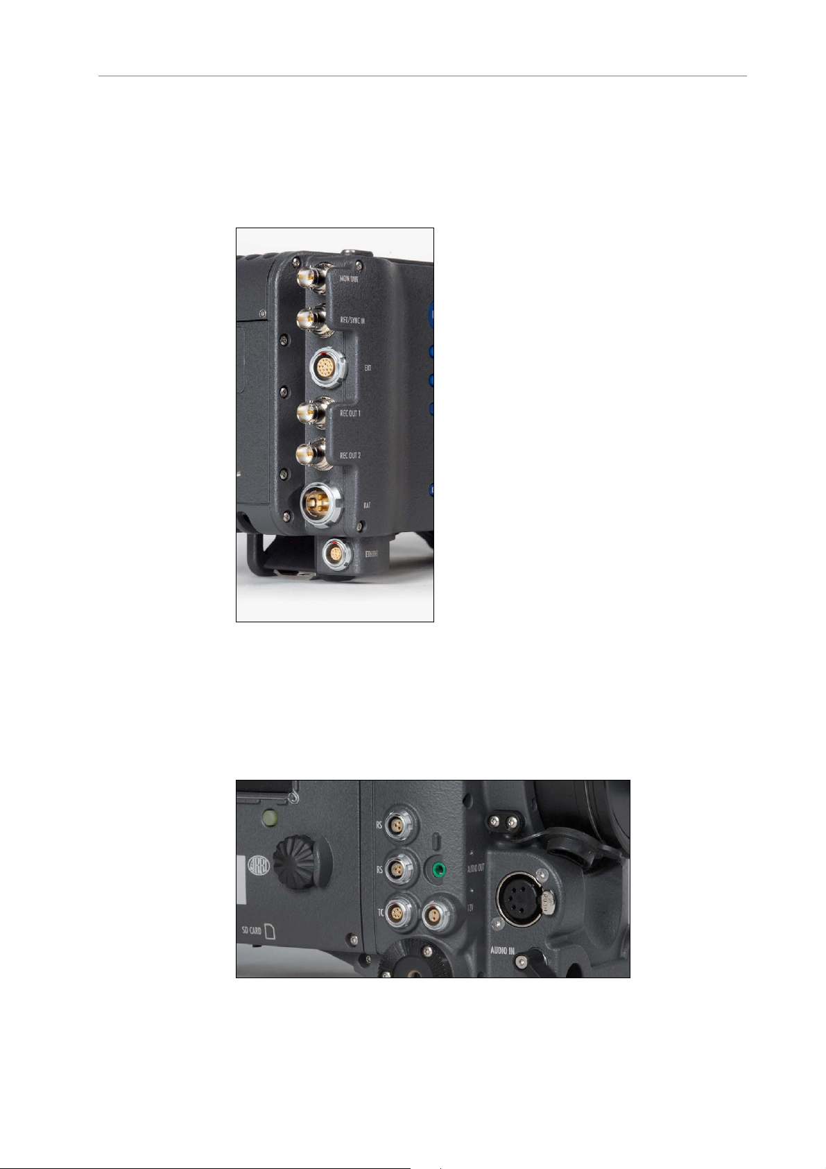
Camera right
Figure 31: Connectors on right side
From left to right, top to bottom: 2x RS (24 V) out, AUDIO OUT, TC, 12V
out, AUDIO IN, SD CARD (camera bottom)
Page 49
Shoulder Pad SP-3 49
Camera left
For ALEXAs with SxS module:
Figure 32: SxS module
Page 50
50 Connectors
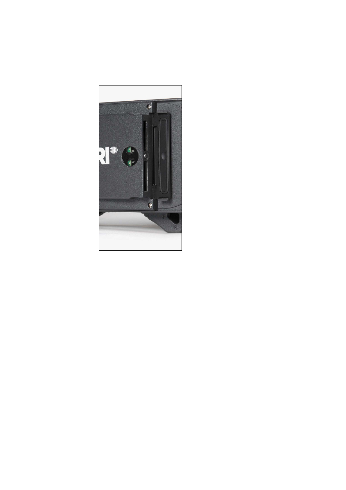
For ALEXAs with XR module:
Figure 33: XR module
Camera front
Figure 34: Camera front
EVF connector
9.1 BAT
The BAT connector can be used to power the camera from an external
power source with cables KC-20S and KC-29S.
Page 51

REC OUT 1 + 2 51
It is located at the back of the camera on the camera-right side.
9.2 REC OUT 1 + 2
The REC OUT consists of two BNC connectors capable of carrying
1920x1080 1.5G or 3G HD-SDI signals with frame rates from 23.976 to
60 fps according to SMPTE standards 274M, 292M, 372M and 425M
(Level B). RGB 444 at frame rates of 48, 50, 59.94 and 60 fps is output in
a proprietary format utilizing two 3G connections. ALEXAs with SxS
module can also output ARRIRAW in a proprietary format (ARRIRAW TLink) that is supported by a range of third-party recorders (not on
ALEXA HD and ALEXA HD Plus). The signal format can be changed in
the Recording menu.
The connectors are located at the back of the camera on the cameraright side.
9.3 RET/SYNC IN
A return signal from another image source can be fed into the ALEXA’s
RET connector for displaying on EVF and/or MON OUT. The signal must
be a 1920x1080 422 1.5G single link according to SMPTE 274M and
292M. The output routing of the RET in signal can be set in the
Monitoring menu.
The connector is located at the back of the camera on the camera-right
side.
9.4 MON OUT
The MON OUT is a single BNC connector capable of carrying a
1920x1080 422 YCbCr 1.5G HD-SDI signal with frame rates of 23.976, 24,
25, 29.97 or 30 fps according to SMPTE standards 274M and 292M. The
signal format can be changed in the Monitoring menu.
The connector is located at the back of the camera on the camera-right
side.
9.5 EXT
The EXT connector is a multi-pin accessory connector that carries
signals for communication with various accessories and 24V power.
The maximum power output is 2.2A, shared with the RS outputs.
Cables are currently available for:
• Connecting a UMC-3 remote motor controller
Page 52

52 Connectors
(model UMC Connection Cable (0.80m/2.6ft) K-UMC3-ALEXA)
• Connecting two ALEXA cameras for synchronized operation
(model EXT to EXT Cable (2.00m/6.6ft) KC 155-S)
The connector is located at the back of the camera on the camera-right
side.
9.6 ETHERNET
Standard Ethernet connectors can deliver neither the power nor the
durability and reliability required by ARRI, so the ALEXA uses a
specially designed 10-pin LEMO connector. The ARRI KC-153-S cable is
required to connect the Ethernet socket to a standard RJ-45 Ethernet
port.
The Ethernet port can be used to operate two ALEXA cameras with
synced settings by connecting the cameras with a KC 156-S cable, or to
connect the Remote Control Unit RCU-4 to the camera.
The Ethernet connector can output 24 V with 1.2 A power.
The connector is located at the back of the camera on the camera-right
side.
9.7 EVF
The EVF connector connects the camera to an EVF-1 electronic
viewfinder. The signals on this connector are proprietary and can only
be used to drive an EVF-1. This proprietary signal assures low latency
for the viewfinder image.
The connector is located at the front of the camera on the camera-left
side.
9.8 AUDIO IN
2-channel analog line-level audio can be fed to the camera via the 5-pin
XLR connector located at the front of the camera on the camera-right
side.
The ALEXA converts the audio signal from analog to 24 bit 48 kHz PCM.
Page 53

RS 53
9.9 RS
9.10 12 V
The two RS connectors supply external accessories with at least 24 V
power and a combined load of up to 2.2 A (shared with the EXT
connector power out). The sockets also accept an ARRI remote
start/stop trigger.
The connectors are located at the front of the camera on the cameraright side.
The 12 V connector supplies an external accessory with 12 V power and
up to 2.2 A current.
The connector is located at front of the camera on the camera-right
side.
9.11 TC
The TC connector is a 5pin LEMO socket. It accepts and distributes a
Longitudinal Time Code (LTC) signal.
It can be used to
• jam-sync the ALEXA's time code to a Clockit, TC Slate or another
camera
• transmit the ALEXA's time code to a Clockit, TC Slate or another
camera
• tune the frequency of the ALEXA’s crystal oscillator with an
Ambient ACC Clockit Controller
The connector is located at the front of the camera on the camera-right
side.
9.12 AUDIO OUT
The AUDIO OUT is a 3.5mm TRS connector (headphone jack), which
outputs audio fed to the 5-pin XLR AUDIO IN connector with a
maximum power of 2.5 dBm.
The connector is located at the front of the camera on the camera-right
side.
Note: Connecting headphones to the camera while recording can cause a short
audio signal interruption due to static electricity.
Page 54
54 Connectors
9.13 SD Card
The ALEXA saves data such as user setups, frame grabs and system
logs to an SD card. Firmware, additional frame lines and ARRI Look
Files are loaded onto the camera from the SD card. The SD card slot is
located on the bottom of the camera on the camera-right side. To
access the SD card slot, slide the door towards the front of the camera.
SD Card Requirements
• SD or SDHC card (most brands are compatible)
• maximum capacity of 4GB
• FAT or FAT32 format
Note: Keep the SD card slot door closed to prevent dirt and moisture from
entering the camera.
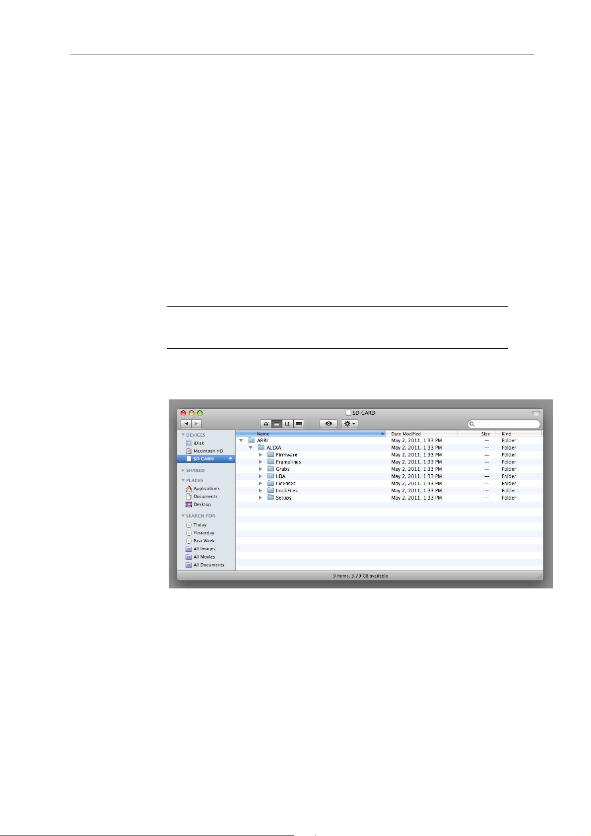
The SD card can be formatted on the ALEXA or the following folder
structure can be created manually on a computer. The SD card must be
properly formatted prior to its first use.
Figure 35: Folder structure required for SD card
To format an SD card on the ALEXA:
1. Press the MENU button.
2. Using the jogwheel, select System.
3. Select SD Card.
4. Select Format + prepare SD card.
5. Press both FORMAT buttons simultaneously. The ALEXA will create
the required folder structure on the SD card after formatting.
Page 55

SxS Slots 55
Note: Formatting the SD card will irreversibly remove all data on the SD card.
To create the required folder structure on the SD card in the
ALEXA without formatting:
1. Press the MENU button.
2. Using the jogwheel, select System.
3. Select SD Card.
4. Select Prepare SD card. The ALEXA will create the required folder
structure on the SD card without formatting or deleting any data.
Note: Firmware update files are recognized by the camera anywhere within the
structure, but it is recommended to copy them into the Firmware folder.
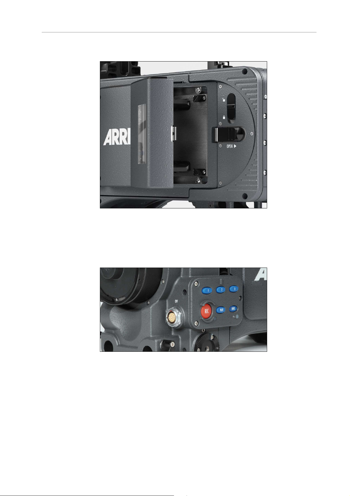
9.14 SxS Slots
This section is only relevant for ALEXAs with SxS module.
The ALEXA records clips using the SxS module on the camera-left side.
The two SxS card slots can be accessed by opening the SxS door
towards the camera body. The SxS door was designed for accessibility
when the ALEXA is operated in confined spaces or mounted on rigs
such as remote heads.
The ALEXA supports both SxS PRO cards as well as SxS PRO+ cards.
For the remainder of this manual, whenever SxS PRO is mentioned,
this applies to SxS PRO+ likewise.
Note: Keep the SxS slot door closed to prevent dirt and moisture from entering
the camera.
To load an SxS card:
1. Insert the SxS PRO card into the SxS slot with the contacts facing
the front of the camera and the label facing out (away from the
camera body).
2. Push the card in against the spring until the lock engages.
3. Close the SxS door.
Note: Do not force an SxS PRO card into the slot backwards or with the labelside in—the contacts in the SxS module and the SxS PRO card could be
damaged.
Note: Do not force the SxS door closed if the SxS PRO card is not fully
inserted and the lock engaged.
Page 56

56 Connectors
To release an SxS card:
• Push the SxS PRO card in until the lock disengages, taking care
to prevent the card from dropping out of the SxS slot.
SxS PRO cards do not have to be mounted or unmounted—they can
be inserted or removed whenever the camera is not recording to the
SxS module. If a card is removed during recording, only the last
second of the current clip will be lost. All clips on the card will remain
accessible and the card will remain fully functional.
Note: If the recording process is interrupted by power loss or card removal,
transfer all the data from the SxS PRO card and format it before using it again.
To toggle between SxS slots:
• With the SxS door open, press the metal card select button
located between the SxS slots. The active SxS slot is indicated
by the LED in the SxS window.
Explanation of SxS LED States
Each card has an LED that signals the SxS PRO card's state to the user.
LED state Card state
Off No card present
Card is unreadable (e.g. wrong file
system)
Card is inactive
Solid green Card is selected and ready
Solid red Card is accessed (read/write)
DO NOT REMOVE THE CARD!
Note: Only Sony SxS PRO cards can be used with ALEXA. Sony SxS-1 cards
are not supported.
Page 57
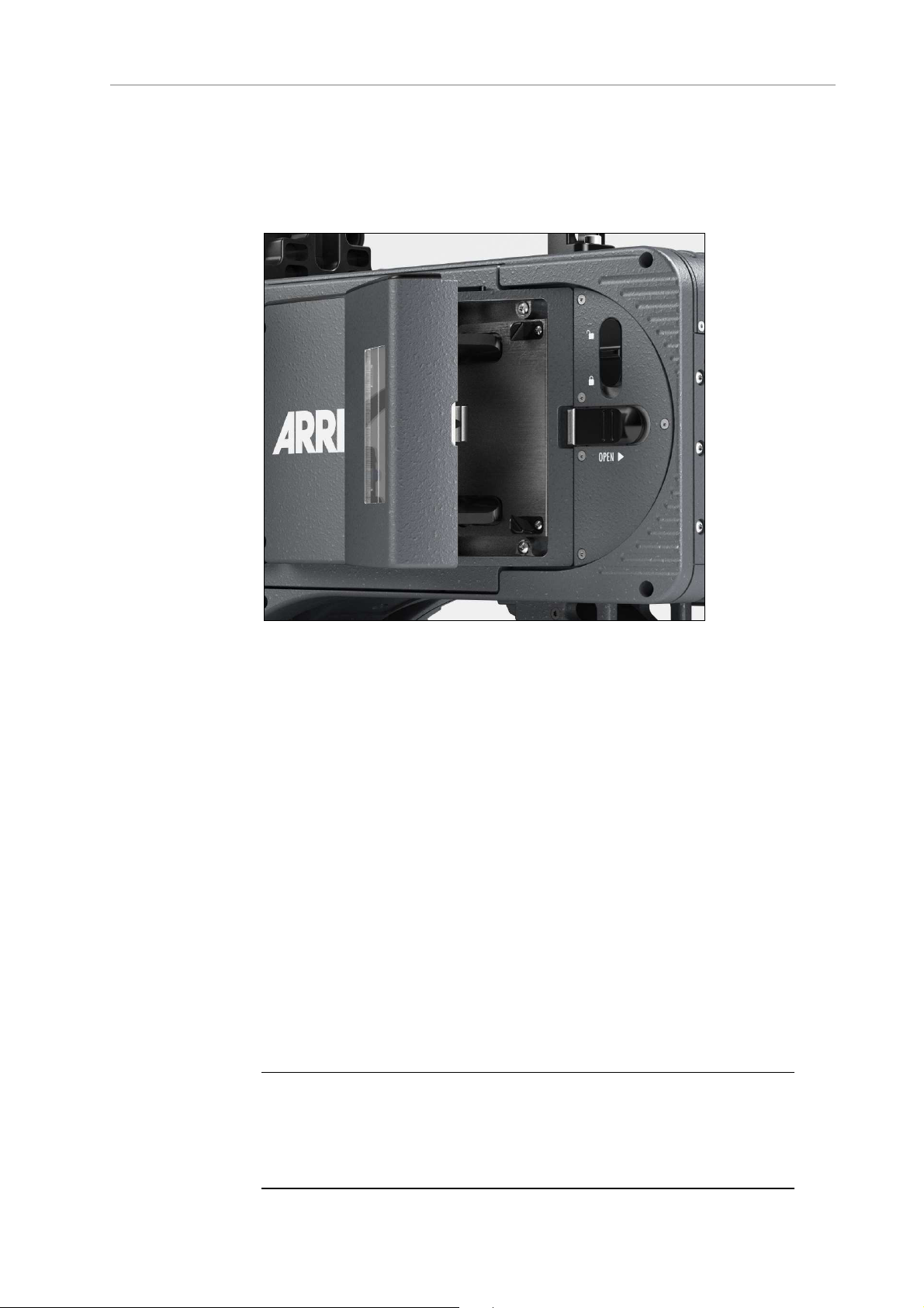
XR (Xtended Recording) Module 57
9.15 XR (Xtended Recording) Module
This section only applies to ALEXAs with XR module.
Figure 36: XR module
The ALEXA records clips using the XR (Xtended Recording) module on
the camera-left side. The media slot can take XR Capture Drives, SxS
PRO and Sxs PRO+ cards with the SxS Adapter or CFast 2.0 cards
with the CFast 2.0 Adapter.
When the ALEXA is in ProRes mode, it can record onto SxS PRO and
Sxs PRO+ cards, CFast 2.0 cards or XR Capture Drives. They do not
need to be loaded or unloaded, but can be used directly after insertion
and can be safely removed whenever they are in standby.
When the ALEXA is in ARRIRAW mode, it can only record onto XR
Capture Drives, which need to be loaded after insertion and unloaded
prior to removal. Refer to the respective sections below for more
information.
To access the media slot, slide the OPEN slider towards camera back so
that the spring-loaded door jumps open.
Putting the lock slider in the (lower) lock position prevents accidental
opening of the door. Ensure that the lock slider is in the (upper)
unlocked position before attempting to open the door.
Note: Keep the door closed to prevent dirt and moisture from entering the
camera.
Note: Only Sony SxS PRO and SxS PRO+ cards can be used with ALEXA.
Sony SxS-1 cards are not supported.
Page 58

58 Connectors
Note: For the remainder of this manual, whenever SxS PRO is mentioned, this
applies to SxS PRO+ likewise.
Inserting media:
To load an XR Capture Drive:
1. Insert the XR Capture Drive into the media slot with the contacts
facing the front of the camera and the ribbed side facing out (away
from the camera body).
2. Push the XR Capture Drive towards camera front until the lock
engages.
3. Close the door.
When the camera is in ARRIRAW mode, it automatically loads the XR
Capture Drive when the door has been closed, see "Explanation of LED
States" below. If closing the door is not possible, e. g. because it has
been damaged, loading an XR Capture Drive can also be triggered by
pressing and holding the eject button for about five seconds.
Loading an XR Capture Drive in ARRIRAW mode normally only takes a
few seconds. In certain situations, however, it may take up to 30
seconds, especially when an XR Capture Drive has been removed
previously without unloading it properly.
Note: Do not put any labels or adhesive tape on the back of an XR Capture
Drive (the side facing the camera body). The XR Capture Drive must have full
contact to the camera body to ensure proper heat conduction.
To insert the SxS Adapter or the CFast 2.0 Adapter:
1. Insert the adapter into the media slot with the contacts facing the
front of the camera and the aperture facing out (away from the
camera body).
2. Push the securing levers on top and bottom of the adapter and push
it towards camera front until the lock engages.
To load an SxS PRO card or CFast 2.0 card:
1. Insert the card into the adapter with the contacts facing the front of
the camera and the label facing out (away from the camera body).
2. Push the card in against the spring until the lock engages.
3. Close the door.
Note: Do not force any media into the slot or into the adapter in wrong
orientation—the contacts could be damaged.
Note: Do not force the door closed if the media is not fully inserted.
Page 59

XR (Xtended Recording) Module 59
Removing media:
When the camera is in ProRes recording mode, SxS PRO cards, CFast
2.0 cards and XR Capture Drives do not have to be mounted or
unmounted—they can be inserted or removed whenever the camera is
not recording. If media is removed during recording, only the last
second of the current clip will be lost. All clips on the media will remain
accessible.
When the camera is in ARRIRAW recording mode, XR Capture Drives
need to be unloaded before they can be safely removed. Unloading is
triggered automatically when the door is opened and the XR Capture
Drive is in standby. When the door is already open, but the XR Capture
Drive is still loaded, press the eject button on the XR Capture Drive to
trigger unloading. See "Explanation of LED States" below for
information about how the camera signals loading state.
Note: If the recording process is interrupted by power loss or media removal,
transfer all the data from the media and format it before using it again.
Before removing any media, open the door by sliding the OPEN slider
towards camera back. Ensure the lock slider is in the (upper) unlocked
position, otherwise the OPEN slider will be blocked.
To remove an XR Capture Drive:
• Carefully pull the XR Capture Drive towards camera back, taking
care not to drop it accidentally.
To remove an SxS PRO card or CFast 2.0 card:
• Push the card in until the lock disengages, then pull the card out
backwards, taking care to prevent the card from dropping out of
the adapter.
To remove the SxS Adapter or CFast 2.0 Adapter:
• Push the securing levers on top and bottom of the adapter and
pull it towards camera back, taking care not to drop it
accidentally.
It is possible that XR Capture Drives will get hot to the
touch during extended operation and can cause pain or
even burns if held for too long. It is advisable to handle
the drive for no more than three seconds, and to remove
the drive quickly and carefully. Allow it to cool before
further handling and consider wearing protective gloves.
Explanation of LED States
XR Capture Drives, SxS Adapter and CFast 2.0 Adapter have an LED
that signals the media's state to the user.
Page 60

60 Connectors
LED state Card state
Off
Solid green Media is in standby and ready
Solid red Media is being accessed (read/write)
Red flashing Media error, see camera for details
Blue flashing
(XR Capture Drive only)
Solid blue
(XR Capture Drive only)
• No media present
• Media is unreadable (e.g. wrong
file system)
• Media is inactive
DO NOT REMOVE THE CARD!
XR Capture Drive is being loaded or
unloaded
XR Capture Drive is unloaded and can
be ejected safely
Page 61

Lens Adapter PL Mount LA-PL-1 (no LDS) 61
10 Lens Mounting
The ALEXA is equipped with an interchangeable lens mount.
Note: Lenses must cover an image circle of at least 27.3 mm for 16:9 sensor
mode, 29.7 mm for 4:3 sensor mode and 33.5 mm for Open Gate sensor mode
to prevent vignetting.
10.1 Lens Adapter PL Mount LA-PL-1
(no LDS)
The Lens Adapter LA-PL-1 is the standard lens mount delivered with the
ALEXA. It can be used to attach any modern PL-mount lens to the
camera.
To mount a PL-mount lens:
urn the bayonet ring anti-clockwise until it stops.
1. T
2. Remove the lens port cap.
3. Carefully insert the lens into the lens port. Align the notch in the
lens flange with the index pin on the mount, keeping the lens
rotated into a position where the lens markings are visible from
either side of the camera.
4. Press the lens flange flat onto the lens mount.
5. Turn the bayonet ring clockwise until the lens is locked securely.
6. Ensure that the lens is properly mounted.
Note: When no lens is attached to the camera, use the lens port cap to prevent
dust from entering the lens cavity.
Note: The sophisticated design principle of the camera’s optical module
delivers outstanding images with a cinematic look and feel, but also makes the
imager sensitive to contamination. Dust particles that have settled on the
sensor cover glass during a lens change may become visible as dark spots in
the output image, similar to lint leaving marks on exposed film. The degree of
this effect depends on the aperture of the lens.
Page 62

62 Lens Mounting
Figure 37: PL mount LA-PL-1 with index pin
10.2 Lens Support
Heavy lenses may require additional lens support. Using a lens support
guarantees that the weight of the lens will not influence the flange focal
depth and reduces stress on the lens mount.
To support a lens use 15mm studio or 19mm studio rods and an
appropriate lens bridge. 15mm studio rods require a bridge-plate with
15mm studio rod support, such as a BP-3/BP-9 + BPA-1, while 19mm
studio rods require a bridge-plate with 19mm studio rod support, such
as a BP-12 or BP-5/BP-8 + BPA-1.
Mount the lens bridge LS-10 for 15 mm studio rods by pushing it onto
the rods from the front. Mount the lens bridge LS-9 for 19 mm studio
rods by clipping it on the rods from the top.
Page 63

Lens Support 63
Slide the bridge into position on the rods directly under the lens
support ring on the lens, and fix it in place by tightening the lever on its
side. Align and tighten the center screw in the lens support ring,
adjusting the height of the center screw with the lever on the back of
the lens bridge.
Figure 38: ALEXA with BP-12, 19mm studio rods and lens bridge
Page 64

64 Camera Controls
11 Camera Controls
The ALEXA can be controlled through three user interfaces:
Main controls Location: camera-right side
Interface: 3-inch LCD-screen with floatingfunction buttons, a jogwheel to navigate
through menus and adjust parameters, and a
range of fixed-function buttons.
Operator controls Location: camera-left side
Interface: three assignable function buttons
plus three fixed-function buttons for easy
operator access.
EVF controls Location: Electronic Viewfinder EVF-1
Interface: fixed function buttons and a
jogwheel for adjustment of viewfinder
parameters and primary shooting parameters.
Page 65

Main Controls 65
11.1 Main Controls
The main controls can be used to set all camera parameters.
Figure 39: Main controls
11.1.1 Display
The 3-inch LCD has a resolution of 400x240 pixels. The back-lit,
transflective display has exceptional contrast even in bright sunlight.
To adjust the LCD brightness:
• On the HOME screen, rotate the jogwheel while pressing the
BACK button.
A plastic shield protects the display from scratches. It can be removed
by pulling it off the four pins.
11.1.2 Screen Buttons
Six screen buttons are located above and below the LCD display. Their
function varies depending on the screen content and is shown directly
above or below each button. If no function is shown above or below a
button on the LCD, it has no function for that screen.
Page 66
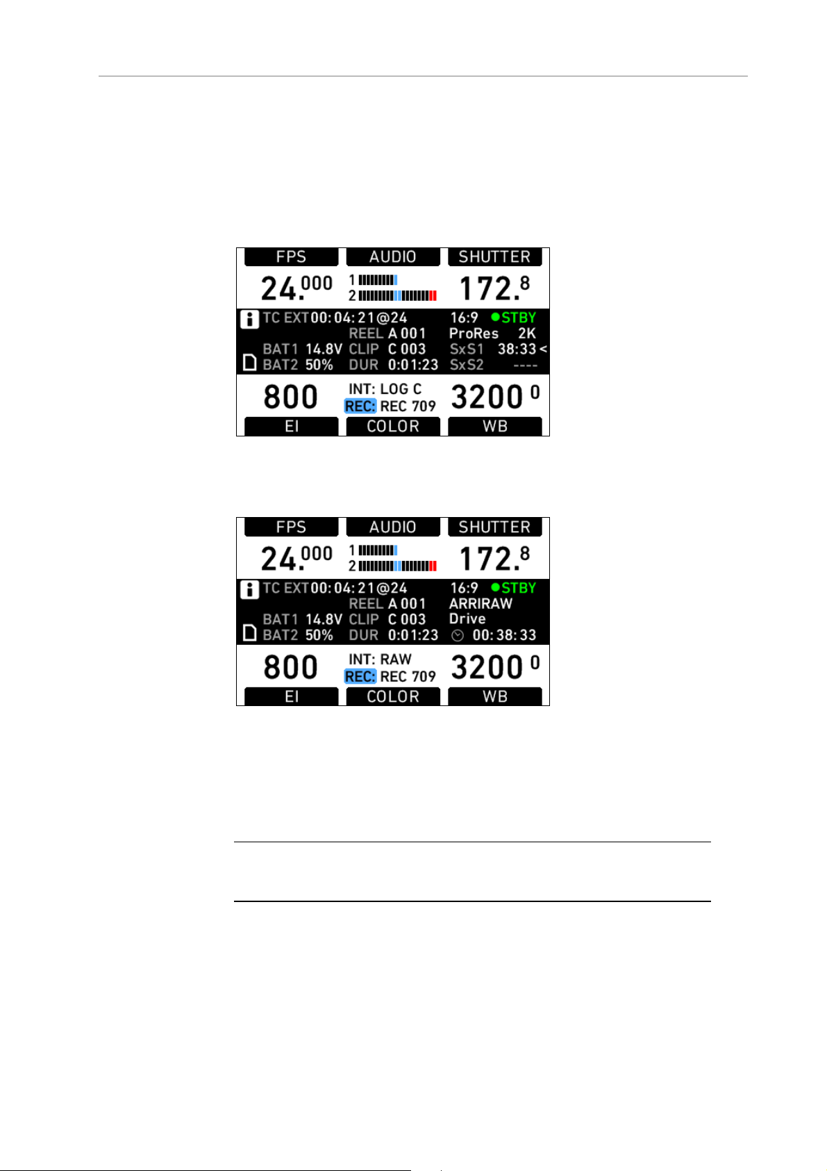
66 Camera Controls
As a failsafe, operations that cannot be reversed and can result in the
loss of data require pressing two buttons simultaneously to confirm the
operation.
11.1.3 HOME screen
Figure 40: HOME screen with SxS module
Figure 41: HOME screen with XR module
The HOME screen is the ALEXA’s default screen. It shows the most
important camera parameters and gives quick access to changing them
through the screen buttons. To return to the HOME screen from any
menu in the camera, press the HOME button.
Note: To adjust the LCD brightness from the HOME screen, rotate the jogwheel
while pressing the BACK button.
Page 67

Main Controls 67
Screen buttons
Button Function
FPS Sets the frame rate of the sensor, adjustable from 0.750-60.000
fps in Regular Speed Mode, and from 60.000-120.000 fps in
High Speed Mode.
Note: High Speed Mode can only be activated with a valid High
Speed license key installed in the camera. Some camera models
have the High Speed license pre-installed.
AUDIO Shows the current audio level. If AUDIO is set to Off, the audio
input is switched off: no audio is embedded in the HD-SDI
outputs, and no audio tracks are recorded onto internal media.
The same applies if AUDIO is disabled, which is the case if the
sensor frame rate is different from the project fps setting (for
example, while over- or undercranking).
SHUTTER Sets the shutter angle of the sensor, adjustable from 5.0-358.0°.
Shutter angle and sensor fps determine exposure time of the
sensor in seconds by the following equation: angle/(360*fps).
Note: In High Speed mode, the shutter angle is limited to a
maximum of 356.0°.
EI Sets the exposure index rated in ASA. The ALEXA has a base
sensitivity of 800 ASA. The camera’s EI rating can be adjusted
from 160 to 3200 ASA.
Note: ASA rating is identical to ISO rating.
Note: Exposure Index is not applied to ARRIRAW signals.
COLOR Opens the color screen, where gamma and look settings for
internal recording (INT), REC OUT, MON OUT and EVF can be
changed.
WB Sets the camera’s white balance. This is the color temperature
of the light source that the ALEXA is currently adjusted for. The
white balance can be adjusted from 2000 to 11000 Kelvin in
steps of 100 Kelvin. In addition to the red/blue correction of the
white balance, the ALEXA can also compensate for a
green/magenta tint. This value, called CC (color compensation),
is shown as an exponent of the WB value. Positive values are
marked with a "+" and negative values with a "-".
The user can execute an automatic white balance by pressing
the AUTO WB button in the WB screen.
Camera Status Section
TC Displays the current time code including the source (INT:
internal, EXT: external source). Frames are not displayed.
The timebase of the time code is shown after the @ sign.
Camera is set to Ext sync: MASTER
Camera is set to Ext sync: SLAVE
Settings sync is active
Page 68
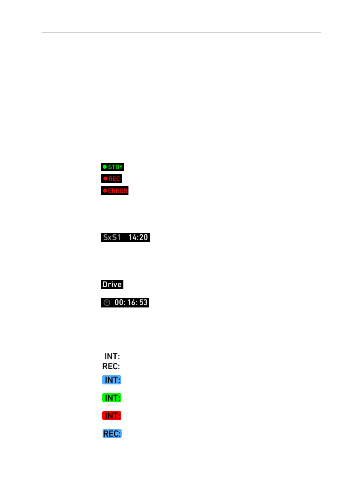
68 Camera Controls
BAT 1 The voltage level of the power source present at the BAT
connector, or the remaining capacity of an attached battery
in percentage if it transmits this information.
BAT 2 The voltage level of a battery attached to the onboard
battery adapter, or the remaining capacity of an attached
battery in percentage if it transmits this information.
REEL Identifies the current reel with the camera index letter, such
as A or B and the reel number.
CLIP Identifies the current clip with the clip index and clip
number.
DUR Displays the duration of the current clip during recording or
the length of the last recorded clip while in standby in the
format h:mm:ss.
Cameras with SxS module
<
Cameras with XR module
COLOR Section
The camera is in standby and ready to record.
The camera is recording.
An error occurred and recording is not possible. Press the
INFO button for more information.
If nothing is shown, the camera has detected no errors, but
no media is present for recording.
Remaining capacity of the currently active SxS PRO card in
minutes and seconds. It is calculated for the current
framerate and codec.*
Marks the active SxS PRO card.
Type of inserted media (XR Capture Drive, SxS PRO, CFast
2.0)
Remaining capacity of the inserted media in hours, minutes,
and seconds. It is calculated for the current framerate and
codec.*
No ARRI Look File is applied to internally recorded footage
nor REC OUT.
The selected ARRI Look File is applied to internally recorded
footage.
The CDL server connection has been enabled and
established (only available when recording ARRIRAW).
(blinking) The CDL server connection has been enabled, but
the CDL server cannot be reached.
The selected ARRI Look File is applied to REC OUT.
Page 69
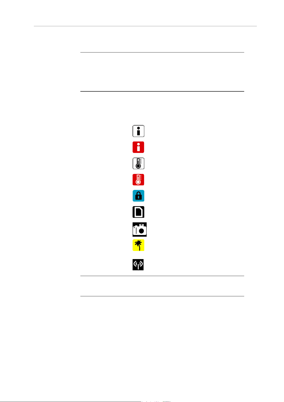
Main Controls 69
* Note: When recording is set to ProResTM, the value shown is the minimum
available recording time for the current sensor frame rate and codec
combination. Apple ProResTM is a variable bit rate codec, so the actual
remaining recording time depends on the image content.
When using Avid's DNxHD, the remaining recording time is accurate.
Icons
Name Icon Description
General Warning
General Error
Temperature
Warning
Temperature Error
Lock
SD Card
Grab
High Humidity
Mode
Radio
Important information is waiting on the INFO
screen.
An error has occurred. Check the INFO screen
for more information.
There is a minor sensor-temperature offset.
Image quality may be slightly affected.
There is a substantial sensor-temperature
offset. Image quality may be seriously affected.
The Main Controls are locked.
An SD card is present. The icon turns orange
when the card is accessed.
The GRAB icon flashes while a still frame is
being taken and written to the SD card.
The sensor is in High Humidity mode (i.e. the
sensor is kept at 40° C sensor temperature to
avoid condensation).
The ARRI Wireless Remote System (WRS) radio
is active.
Note: A sensor temperature warning or error after boot-up is normal as the
sensor takes a few seconds to reach its preset temperature.
11.1.3.1 Lists and User Lists
On the HOME screen, press the FPS, SHUTTER, WB (white balance)
and EI (exposure index) buttons to open lists of preconfigured values
for each setting.
User-defined values can be added to the FPS, SHUTTER and WB lists.
The EI list is fixed and user-defined values cannot be added. It contains
values from 160-3200 ASA in steps of 1/3 stops.
Page 70
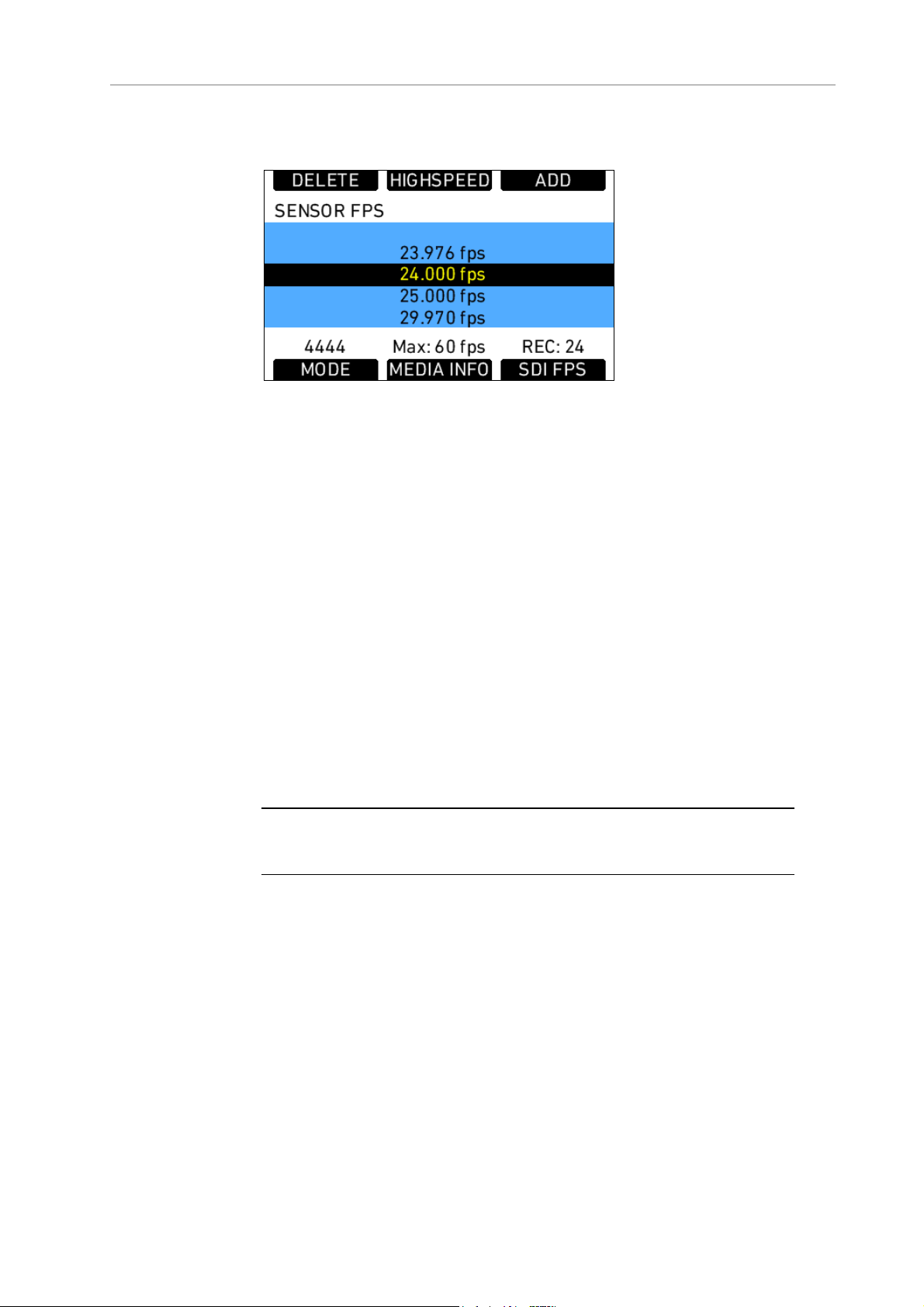
70 Camera Controls
Setting a list value
Figure 42: SENSOR FPS screen
Any value in a list may be set. Invalid values will appear grayed out.
To set a list value:
1. Rotate the jogwheel to select the desired list value.
2. Press the jogwheel to set the list value.
Adding a list value
If the desired list value does not appear in the list, a user-defined value
can be added.
To add a list value:
1. Press the
ADD button.
2. On the ADD screen, use the jogwheel and + or – buttons to enter a
new list value.
3. When you are finished entering the new list value, press the
jogwheel to add it to the list.
Note: Each list supports a maximum of 16 entries. To add new user-defined list
values to a full list, you must delete previously added user-defined list values.
Deleting a list value
User-defined list values that are no longer required can be deleted.
To delete a list value:
1. Press the DELETE button.
2. On the DELETE screen, use the jogwheel to select the user-defined
value you wish to delete.
3. Press both DELETE buttons simultaneously.
Page 71
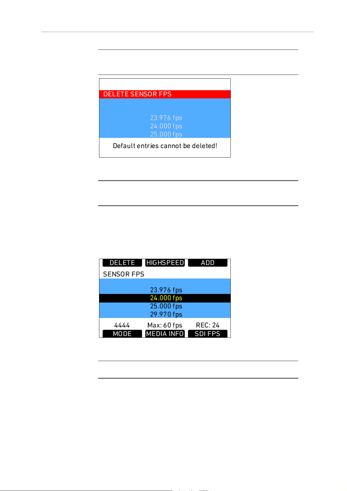
Main Controls 71
Note: Preconfigured values cannot be deleted and will appear grayed out on the
DELETE screen.
Figure 43: DELETE SENSOR FPS screen
Note: The EI list is static and cannot be changed by the user. It contains ASA
values from 160-3200 ASA in steps of 1/3 stop.
11.1.3.2 FPS
Press the FPS (frames per second) button on the HOME screen to open
the SENSOR FPS list screen, which lists the default frame rates as well
as user-defined frame rates.
Figure 44: SENSOR FPS screen
Note: Access to this screen is disabled during record.
The maximum frame rate that can be set is dependent on the type of
media and the codec.
The following table shows the maximum available frame rate for all
codec/media combinations and all ALEXA cameras including the
ALEXA Studio and ALEXA XT Studio with mirror shutter OFF. For a
table of the maximum fps values for ALEXA Studio and ALEXA XT
Studio with mirror shutter on, see the chapter on ALEXA Studio.
Page 72

72 Camera Controls
Codec SxS PRO
32 GB
SxS PRO
64 GB
CFast
2.02
SxS PRO+
64 GB /
128 GB
16:9 HD
ProRes 422 60 fps 60 fps
ProRes 422 HQ 60 fps 60 fps
(120 fps)1
(120 fps)1
60 fps
(120 fps)1
60 fps
(120 fps)1
ProRes 4444 40 fps 60 fps 60 fps
(120 fps)
ProRes 4444 XQ2 25 fps 48 fps 60 fps
(75 fps)1
DNxHD 145 60 fps 60 fps
(120 fps)1
DNxHD 220x 60 fps 60 fps
(120 fps)1
60 fps
(120 fps)1
60 fps
(120 fps)1
DNxHD 444 30 fps 60 fps 60 fps
(90 fps)1
XR
Capture
Drive2
60 fps
(120 fps)1
60 fps
(120 fps)1
60 fps
1
(120 fps)1
60 fps
(75 fps)1
60 fps
(120 fps)1
60 fps
(120 fps)1
60 fps
(96 fps)1
16:9 2K
ProRes 422 60 fps 60 fps 60 fps 60 fps
ProRes 422 HQ 50 fps 60 fps 60 fps 60 fps
ProRes 4444 30 fps 60 fps 60 fps 60 fps
ProRes 4444 XQ2 - 40 fps 60 fps 60 fps
16:9 ARRIRAW 2 - - - 60 fps
(120 fps)1
4:3 2K
ProRes 422 48 fps 48 fps 48 fps 48 fps
ProRes 422 HQ 40 fps 48 fps 48 fps 48 fps
ProRes 4444 30 fps 48 fps 48 fps 48 fps
ProRes 4444 XQ2 - 30 fps 48 fps 48 fps
4:3 ARRIRAW 2
Full
Cropped
48 fps
(90 fps)1
48 fps
(96 fps)1
Page 73
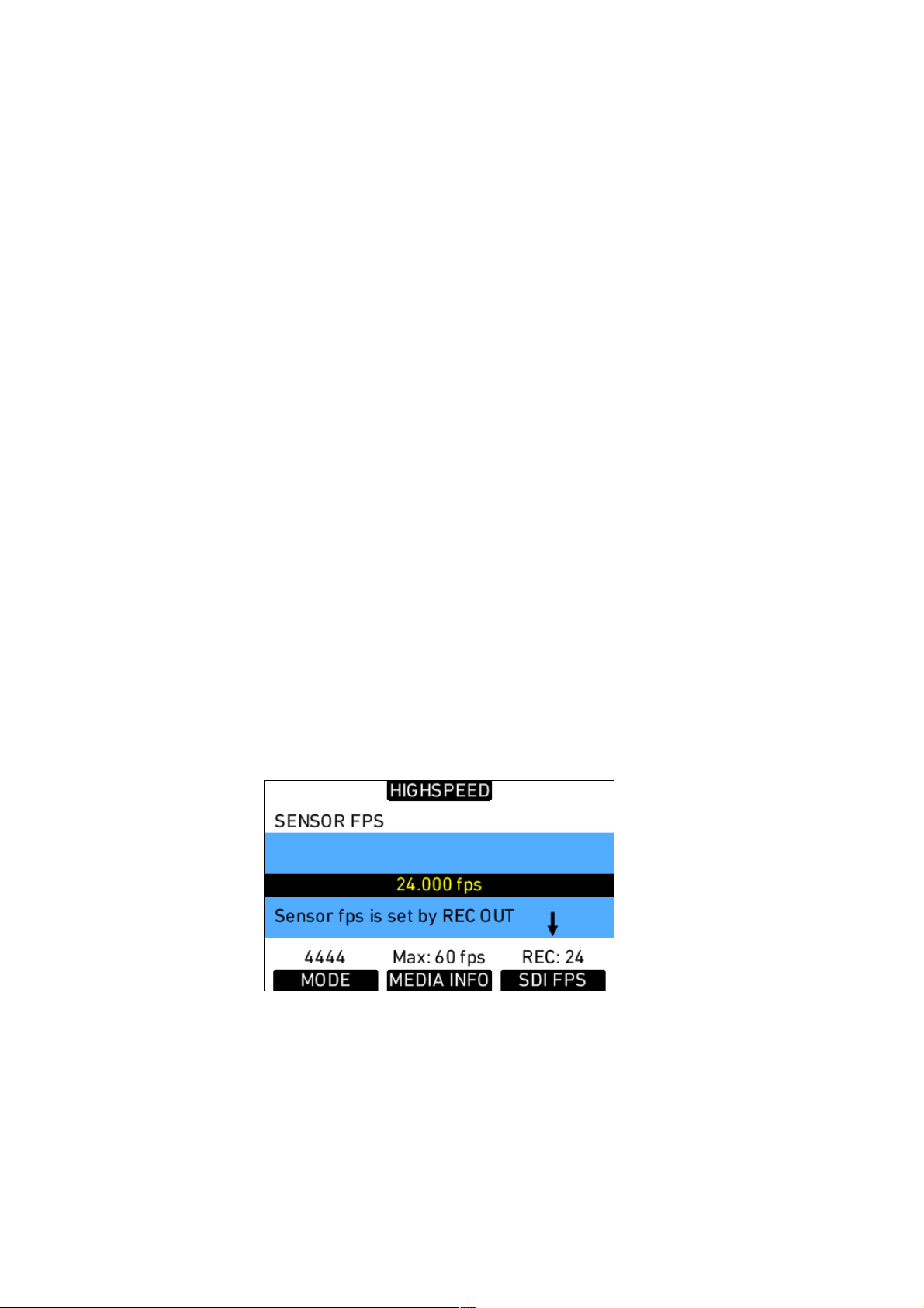
Main Controls 73
Codec SxS PRO
32 GB
SxS PRO
64 GB
SxS PRO+
CFast
2.02
XR
Capture
Drive2
64 GB /
128 GB
Open Gate
75 fps
ARRIRAW 2
1
Requires a High Speed license, see below
2
Only available on ALEXAs with XR module
If the desired frame rate cannot be set because it is grayed out, change
the codec to one with a lower data rate. For example, when using a 32
GB SxS PRO card and the ProRes 4444 codec, 60.000 fps will be
grayed out. Select the ProRes 422 HQ codec to enable 60.000 fps.
There are shortcut buttons on the
FPS screen for CODEC, INFO and SDI
FPS. In the SDI FPS screen, both MON OUT and REC OUT frame rates
can be adjusted within the limits of their current format.
Setting sensor fps through REC OUT fps
When the FPS button is pressed on the HOME screen and the sensor
frame rate is linked to the REC OUT frame rate, a message appears
instead of the list. While this setting is active, the sensor frame rate can
only be set by setting the REC OUT frame rate.
To link or unlink the sensor frame rate to the REC OUT frame rate:
1. Press the
MENU button.
2. On the Recording menu, use the jogwheel to select REC OUT.
3. Select REC OUT fps sets sensor fps and set On or Off.
Figure 45: SENSOR FPS screen with linked sensor frame rate
Page 74

74 Camera Controls
Setting the correct frame rates when recording with external
devices
When recording ARRIRAW T-Link (only on ALEXA Classic cameras) or
the HD-SDI signal from the ALEXA to an external recorder, correct
frame-rate settings are critical. Mismatched sensor and REC OUT frame
rates could result in dropped frames and lost footage.
Setting the sensor frame rate determines the number of frames per
second generated by the sensor. The range for external recording is
0.750 to 60.000 frames per second. The images are then processed by
the camera electronics for the different output paths.
The REC OUT is the recording output path, which transmits images to
an external recorder. The REC OUT frame rate is limited to standard
speeds.
Ideally, the REC OUT frame rate matches the sensor frame rate. If the
REC OUT frame rate is lower than the sensor frame rate, the images
cannot be output as fast as they are created by the sensor, resulting in
dropped frames and loss of data.
Note: If the REC OUT frame rate is lower than the sensor frame rate, a ! warning
will appear over the SDI FPS button.
If the REC OUT frame rate is higher than the sensor frame rate,
duplicate frames are output over the REC OUT. For example, if the
sensor is set to 10 fps and the REC OUT is set to 30 fps, every image is
output three times, resulting in two duplicate frames following every
active frame. A standard recorder would record these duplicate frames,
which would have to be removed in post.
To prevent this extra step, the ALEXA marks the duplicate frames with a
Variflag. If the recorder supports Variflag recording, it will discard the
duplicate frames and only record the active frames. This saves valuable
storage space and post-production work.
The MON OUT should match the sensor and the REC OUT frame rate. If
the sensor frame rate exceeds the available MON OUT frame rates, set
the MON OUT to half the sensor frame rate if possible to maximize the
smoothness of the image when panning and tilting.
To correctly set frame rates for the REC OUT:
1. Press the
MENU button.
2. Using the jogwheel, select the Recording menu.
3. Select REC OUT.
4. Set Frame rate to the desired frame rate. This frame rate should
match the frame rate setting on the external recorder.
5. If the desired sensor frame rate is a standard speed, set REC OUT
fps sets sensor fps to On.
6. Press the HOME button to exit.
Page 75

Main Controls 75
To correctly set frame rates for the MON OUT:
1. Press the MENU button.
2. Using the jogwheel, select the Monitoring menu.
3. Select MON OUT.
4. Set Frame rate to the same frame rate as the REC OUT. If the REC
OUT frame rate exceeds the range of the available MON OUT frame
rates, set the MON OUT frame rate to half the value of the REC OUT
frame rate.
5. Press the HOME button to exit.
To set a non-standard frame rate for the REC OUT:
1. Press the
MENU button.
2. Using the jogwheel, select the Recording menu.
3. Select REC OUT.
4. Set REC OUT fps sets sensor fps to Off.
5. Press the HOME button to exit.
6. On the HOME screen, press the FPS button.
7. Select the desired frame rate from the list or add a user-defined
frame rate (see Adding a list value in Lists and User Lists).
High Speed Mode
If a valid High Speed license key is installed on the ALEXA, frame rates
from 60 to 120 fps are available in 16:9 High Speed mode, from 48 to 90
fps in 'ARRIRAW 4:3 Full' High Speed mode and from 48 to 96 fps in
'ARRIRAW 4:3 Cropped' High Speed mode. Frame rates below 60 fps in
16:9 and 48 fps in 4:3 are not available in High Speed mode. Exit High
Speed mode to record with lower frame rates.
High Speed mode recording is possible only to internal recording
media, not via the REC OUT outputs.
Note: In 16:9 sensor mode, High Speed mode recording is possible in HD
codecs only. In 4:3 sensor mode, High Speed mode is only available when the
recording mode is set to ARRIRAW (only available for ALEXAs with XR
module).
The maximum frame rate in ProRes 2K is 60 fps in 16:9 sensor mode and 48 fps
in 4:3 sensor mode.
For detailed information about which codec/media combination
supports which framerate, please refer to the table above.
To load High Speed mode:
1. On the HOME screen, press the FPS button.
2. On the FPS screen, press the HIGHSPEED button.
Page 76

76 Camera Controls
3. Press both LOAD buttons simultaneously. Loading High Speed
mode takes approximately 20 seconds and is indicated by a
progress bar.
4. After loading, the current High Speed recording mode is displayed.
Press the SET MODE button to change to a different mode.
Note: Starting from 4:3 Normal Speed, the resulting High Speed mode differs
depending on the currently selected recording mode: With ProRes recording
selected, the ALEXA will go to 16:9 High Speed. With ARRIRAW recording
selected, the ALEXA will go to 4:3 High Speed. Exiting High Speed mode will
always return to 4:3 Normal Speed.
To exit High Speed mode:
1. On the HOME screen, press the FPS HS button.
2. On the FPS HIGHSPEED screen, press the EXIT HS button.
3. Press both EXIT buttons simultaneously. Exiting High Speed mode
takes approximately 20 seconds and is indicated by a progress bar.
11.1.3.3 AUDIO
Press the AUDIO button on the HOME screen to open the AUDIO
screen. This screen shows the ALEXA’s two audio channel levels. The
audio levels are displayed from -45 dBFS to 0 dBFS.
Note: No audio meters are displayed on the HOME screen or AUDIO screen
when audio is set to Off or audio is disabled. Audio is disabled when the sensor
frame rate does not match the project frame rate.
Light blue markers show reference levels of -20, -18 and -9 dB FS.
Page 77

Main Controls 77
Red markers at levels -1 and 0 dBFS warn of clipping. With a proper
audio signal levels, the red markers should almost never be visible.
Figure 46: Audio screen
Gain can be applied to the audio channels by turning the jogwheel to
set both channels, or by pressing the CH 1+, CH 1-, CH 2+ and CH 2-
buttons. The amount of gain applied by the camera is indicated next to
the levels as light gray numbers.
Press the OPTIONS button to open the AUDIO IN>OPTIONS screen and
set audio parameters.
Figure 47: AUDIO IN>OPTIONS screen
Option Description
Record Turns audio recording On or Off.
If audio recording is switched off, no audio
is recorded internally, the HD-SDI contains
no audio and the Audio out is muted.
Channel 1 level Manual allows the user to manually apply
gain to the input signal on channel 1 to
reach a correct level.
Unity matches a 4 dBu input signal to -20
dBFS. This setting leaves enough headroom
for recording and avoids audio clipping.
When Unity is selected, audio levels cannot
be adjusted by the user.
Page 78

78 Camera Controls
Channel 2 level Manual allows the user to manually apply
gain to the input signal on channel 2 to
reach a correct level.
Unity matches a 4 dBu input signal to -20
dBFS. This setting leaves enough headroom
for recording and avoids audio clipping.
When Unity is selected, audio levels cannot
be adjusted by the user.
Channel 1 source Select the left or right input signal as the
source for Channel 1.
Channel 2 source Select the left or right input signal as the
source for Channel 2.
Soundroll (=Tape) Enter a name for the sound roll (also known
as Tape in the menus of some recorders) of
an external audio recorder, for easier sound
synching in post-production. The name will
be written to the FCP XML file and the Avid
Log Exchange (ALE) file on the recording
media.
Figure 48: Audio out screen
Press the AUDIO OUT button to open the AUDIO OUT>OPTIONS screen
where the global volume for both Audio out channels can be adjusted.
The OPTIONS button opens a list of AUDIO OUT options.
Figure 49: AUDIO OUT>OPTIONS
Left out Sets which channel is routed to the left
output.
Page 79

Main Controls 79
Right out Sets which channel is routed to the right
output.
Audio out level Set the level of the audio out channels
manually, or set it to fix the maximum
output.
Note: These settings do not influence the audio signal embedded in the HD-SDI
connectors or recorded in QuickTime clips. They only affect the AUDIO OUT
connector!
Note: ALEXA automatically determines the internal signal run time and
matches audio and images so they are always in sync. When changing sensor
fps or project fps, it may take up to 2 seconds for the camera to resync image
and audio signals.
11.1.3.4 SHUTTER
Press the SHUTTER button in the HOME screen to open the SHUTTER
ANGLE screen.
Note: Access to this screen is disabled during record.
The list of default shutter angles includes 11.2°, 22.5°, 45.0°, 90.0°,
172.8°, 180.0°, 270.0° and 358.0°. User-defined shutter angles can be set
by pressing the ADD button. The exposure time for the current frame
rate and shutter angle is indicated in seconds at the bottom of the
SHUTTER ANGLE screen.
The shutter angle range is 5.0° to 358.0°. In High Speed mode, the
shutter angle is limited to a maximum of 356.0°.
Below the list, the actual exposure time at the currently set frame rate is
shown.
Note: Be aware that the combination of long exposure times (a low sensor
frame rate and large shutter angle) and high exposure indexes can lead to
image artifacts! Try to avoid exposure times longer than 1/25th of a second for
maximum image quality.
Page 80

80 Camera Controls
Figure 50: Shutter list
11.1.3.5 EI
The Exposure Index (EI) is the applied sensitivity of the camera.
The ALEXA has a base sensitivity of 800 ASA. This means that the
dynamic range is almost evenly distributed above and below neutral
gray with low noise in the shadows and clean, smooth clipping
behavior in the highlights.
Due to its high dynamic range, the ALEXA’s sensitivity can be set from
160 to 3200 ASA in steps of 1/3 stops while maintaining high image
quality.
Figure 51: Exposure Index screen
Note: The Exposure Index list has fixed content, meaning that it cannot be
changed by the user.
Applying the exposure indexes at the extremes of the range will
nonetheless have an influence on the images. At low exposure indexes,
such as 160 ASA, the dynamic range below neutral gray increases,
reducing noise even further. At the same time, the dynamic range
above neutral gray is slightly reduced. Highlight clipping itself is not
influenced by this, but the shoulder of the gamma curve will get slightly
steeper, reducing the smoothness of the change from almost
overexposed to overexposed.
Page 81
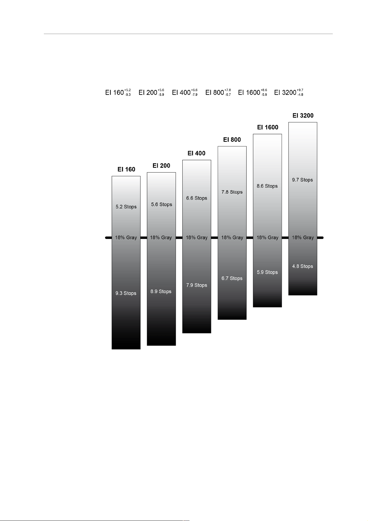
Main Controls 81
At high exposure indexes, such as 1600 ASA, the images behave in the
opposite way. Noise is increased, which makes it important to judge
shadow detail, while there will be even more headroom in the
highlights.
11.1.3.6 COLOR
Press the COLOR button to open the COLOR screen. The COLOR screen
displays a graphical overview of the color management settings applied
to the camera’s output paths, including:
• the current gamma setting of the EVF, MON OUT, REC OUT and
internal recording
• which ARRI Look File is set
• which output paths the Look File is applied to
Page 82
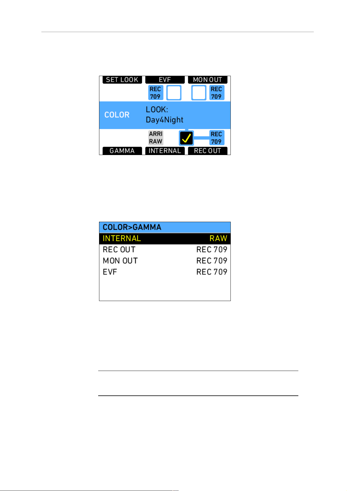
82 Camera Controls
The COLOR screen also has buttons for opening the GAMMA screen,
selecting a Look File, and applying Look Files to the camera’s output
paths.
Figure 52: COLOR screen
Gamma
Press the GAMMA button to open the GAMMA screen and set the
gamma of the internal recording, REC OUT, MON OUT and EVF image
paths.
Figure 53: GAMMA screen
Gamma defines the contrast curve that is applied to the image. In the
ALEXA, there are two gamma settings for color images (not ARRIRAW)
available:
• LOG C
• REC 709
Note: Starting with SUP 7.0, DCI P3 is no longer available as a gamma since it
was seldom used but frequently led to confusion.
Page 83

Main Controls 83
LOG C LOG C is a logarithmic gamma based on the
Cineon format for output to film print or digital
intermediate. Color-grading is a required postproduction step in the LOG C workflow. Standard
broadcast monitors cannot properly display LOG
C images so a conversion look up table (LUT) is
necessary for display, dailies and editing proxies.
LOG C images will appear flat and desaturated
when displayed on standard broadcast monitors.
ALEXA preview LUTs can easily be generated
using the ARRI LUT Generator, a web application
available on www.arridigital.com.
REC 709 REC 709 is a video display gamma that complies
with the ITU.R-BT709 standard. REC 709 images
can be displayed on standard broadcast monitors.
ARRI Look Files
ARRI Look Files are a way for the user to alter the parameters the
ALEXA uses when converting the sensor image data to a video color
space. This can be described as applying a custom "look" to the
different image output paths. The ARRI Look File can be applied directly
to the recorded image (destructive workflow), or just to the monitoring
paths and included in the clip as metadata only (non-destructive
workflow).
The ALEXA contains one preloaded ARRI Look File called Low Contrast
Curve (LCC). This ARRI Look File contains a custom tone map curve that
creates a video image with lower contrast compared to the standard
REC 709 output. As a result, the image holds as much dynamic range
information as possible, without using LOG C encoding. Highlight and
shadow detail that would be lost in the typical REC 709 tone mapping
can still be accessed.
ARRI LOOK Creator, a free application from ARRI, and some third-party
applications can be used to create ARRI Look Files from DPX-format
frame grabs taken on the ALEXA.
To apply an ARRI Look File:
1. On the HOME screen, press the COLOR button.
2. Press the SET LOOK button.
3. Using the jogwheel, select an ARRI Look File from the list on the
LOOK FILES screen. The default preloaded ARRI Look File is LCC.
4. Press the jogwheel to set the ARRI Look File.
On the COLOR screen, press the EVF, MON OUT, INTERNAL and/or REC
OUT buttons to apply the ARRI Look File to the desired output paths. An
applied ARRI Look File is indicated by a check mark in the box
corresponding to each output path. ARRI Look Files can only by applied
to output paths that are set to REC 709 gamma.
Page 84

84 Camera Controls
Note: If the INTERNAL or REC OUT paths are set to REC 709 gamma and an
ARRI Look File is applied, the recorded image on the internal media or external
recording device will be permanently altered by that ARRI Look File.
Note: If both the INTERNAL and REC OUT paths are set to REC 709 gamma, an
ARRI Look File can only be applied to both or none of them.
Additional ARRI Look Files can be added to the ALEXA from the SD
card. The ARRI Look Files must be copied into the LookFiles folder on
the SD card. The required folder structure on the SD card can be
created via MENU>System>SD card>Prepare SD card.
To add an ARRI Look File to the camera:
1. On the HOME screen, press the COLOR button.
2. Press the SET LOOK button.
3. Press the ADD button.
4. Using the jogwheel, select an ARRI Look File from the list on the
LOOK FILES (SD CARD) screen.
5. Press the jogwheel to add the ARRI Look File. The ARRI Look File
will be added to the list on the LOOK FILES screen.
To delete an ARRI Look File from the camera:
1. On the LOOK FILES screen, select an ARRI Look File from the list.
2. Press the DELETE button.
3. Press both new DELETE buttons simultaneously. The ARRI Look
File will be deleted from the camera but will remain on the SD card.
Playback and ARRI Look Files
During playback, the camera makes a distinction between clips
recorded in Log C and clips recorded in Rec 709.
When a clip recorded in Log C is played back and an ARRI Look File is
active in the camera, the look will be applied to the clip. Please note
that this is the currently enabled ARRI Look File, as the camera does not
take into account which ARRI Look File was active when the clip was
recorded. It is the responsibility of the user to make sure the correct
ARRI Look File is applied during playback.
When a clip recorded in Rec 709 (with or without an ARRI Look File
baked in) is played back, no ARRI Look File will be applied by the
camera during playback. For the duration of that clip, ARRI Look Files
will be disabled.
Page 85

Main Controls 85
CDL Server Connection
When internal recording is set to ARRIRAW (only available on ALEXA
XT cameras and ALEXA Classic cameras with an XR Module upgrade),
it is possible to configure a CDL server connection instead of using an
ARRI Look File. With a CDL server connection enabled, the ALEXA will
retrieve the CDL information from the CDL server at the beginning of
each recording and store the values in the clip metadata. Additionally,
the ALEXA retrieves the CDL information at the end of each recording
to update the CDL values in case they have been modified during the
shot. The values from the beginning of the shot, however, are still
accessible during offloading as "old" values. Due to technical
limitations, however, it is not possible to directly apply CDL values in
the ALEXA to outputs or recorded material.
To configure a CDL server connection:
1. On the LOOK FILES screen, select CDL CONF.
2. Enter the IP address of the CDL server.
Note: The CDL server must be located in the same /16 subnet as the ALEXA.
Therefore the first two parts of the IP address cannot be changed.
Note: The CDL server must be reachable at port 6666.
To activate/deactivate the CDL server connection:
• On the LOOK FILES screen, press CDL.
When the connection to a CDL server is activated, it is no longer
possible to select an ARRI Look File or apply it to outputs. The gamma
settings for the individual outputs are still available.
Page 86
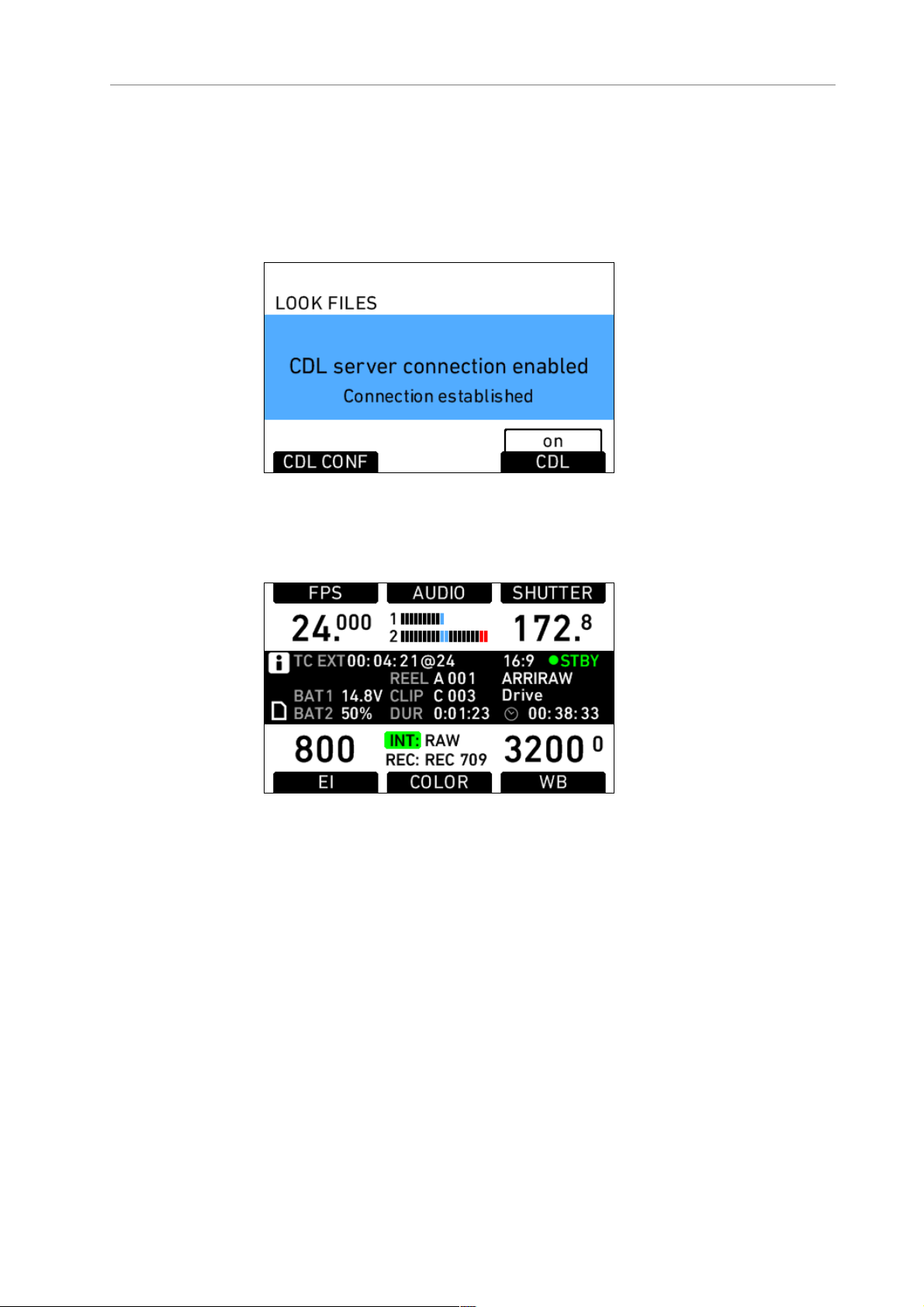
86 Camera Controls
With the CDL server connection enabled, the ALEXA periodically tries to
contact the CDL server and displays the connection status on the LOOK
FILES screen as well as on the HOME screen. When the CDL server
connection is established, INT in the COLOR section of the HOME
screen has a green background, otherwise the background is red and it
is blinking.
Figure 54: LOOK FILES screen with CDL server connection enabled and
established
Figure 55: HOME screen with CDL server connection enabled and
established
11.1.3.7 WB
White Balance (WB) is the color balance of the camera that should be
set to the value appropriate for the light in use. There are three
methods for setting the white balance:
• white balance presets
• user-defined white balance
• automatic white balance
On the HOME screen, press the WB button to open the WHITE
BALANCE screen. The ALEXA has the following white balance presets:
Tungsten 3200K 0CC
Fluorescent 4300K 0CC
Page 87
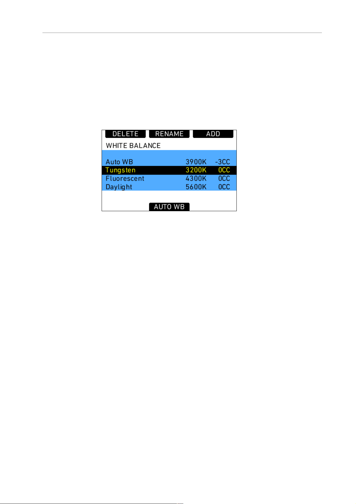
Main Controls 87
Daylight 5600K 0CC
Daylight Cool 7000K 0CC
White balance is a red-blue adjustment of the image. To adjust the
green-magenta balance, use the color compensating (CC) adjustment.
For example, a fluorescent source will have peaks in its spectrum that
cannot be corrected with the traditional white balance. The CC shift can
correct these peaks up to a full green or full magenta gel. One step of
CC SHIFT is equal to 035 Kodak CC values or 1/8 Rosco values.
Figure 56: WHITE BALANCE screen
ARRI recommends adjusting white balance and color compensation
using appropriate measuring equipment such as a vectorscope with
calibrated gray card or a color meter.
If the desired white balance setting does not appear in the WHITE
BALANCE list, a user-defined white balance can be added.
To add a white balance:
1. On the HOME screen, press the
2
. Press the ADD button.
3. Rotate the jogwheel to adjust the white balance value in steps of
100K or press the + 1000K and – 1000K buttons.
4. Press the jogwheel or <> button to select the CC adjustment.
5. Rotate the jogwheel to adjust the CC value.
6. Press the jogwheel to add the new white balance to the WHITE
BALANCE list.
To perform an automatic white balance:
1. On the HOME screen, press the WB button.
2. Press the AUTO WB button.
3. Place a well-lit gray card in the center of the image and press the
AUTO WB button. The ALEXA will calculate the white balance and
color compensation values and set these values for the "Auto WB"
entry in the list.
WB button.
Note: The automatic white balance will be overwritten each time a new
one is calculated.
Page 88
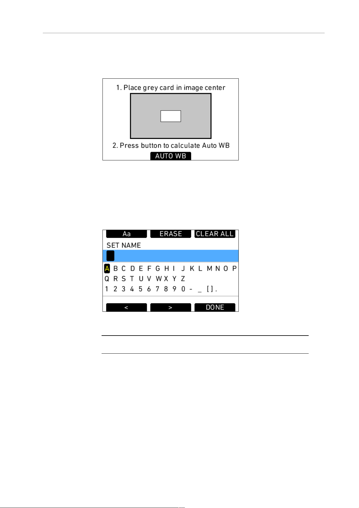
88 Camera Controls
Note: If the gray card is significantly over- or underexposed, the ALEXA
may not be able to calculate a white balance value and will display an
error message.
To rename a white balance:
1. On the HOME screen, press the WB button.
2. Using the jogwheel, select the name of the white balance you wish
to rename.
3. Press the RENAME button.
4. Use the jogwheel to enter a new name.
5. Press the
DONE button to save the new name.
Figure 57: WB SET NAME screen
Note: Default white balance values cannot be renamed.
11.1.4 Function Buttons
The main controls feature the following function buttons:
ON/OFF
Press once to switch the camera on. Press and
hold for 5 seconds to switch off the camera. A
countdown will be displayed on the HOME
screen. If the button is released before the
countdown has elapsed, the camera does not
switch off.
Page 89

Main Controls 89
REC
LOCK
GRAB
TC
WRS
PLAY
Press to start and stop internal recording and
send start and stop record signals over REC OUT
to an external recording device. See section
Prerecording for behavior in prerecording mode.
Press and hold for 3 seconds to lock or unlock
the main camera controls and function buttons.
The recessed function buttons USER, REC and
ON/OFF cannot be locked and remain available. A
lock symbol on the HOME screen indicates that
the lock is engaged.
Press to take a still frame and write it to the SD
card. The write process is indicated by a flashing
camera icon, followed by a flashing SD card icon
on the HOME screen. When writing is finished, a
new still frame can be taken.
Press to open the TIMECODE screen.
Press to open the Wireless Remote System
screen. Available on ALEXA Plus, ALEXA Plus 4:3,
ALEXA M, ALEXA Studio, ALEXA XT Plus, ALEXA
XT M, ALEXA XT Studio and ALEXA HD Plus.
Press to open the playback screen and activate
playback on MON OUT and EVF. When the
playback screen is opened, the last clip on the
internal media that is on active standby will be
loaded automatically.
INFO
USER
MENU
BACK
Press to open the LIVE INFO screen. The LIVE
INFO screen displays the camera’s current system
state and any current error messages. On the
LIVE INFO screen, there are buttons to access the
following additional information screens:
• VERSION
• MEDIA
• SYSTEM
• SAVE TO SD (press to save a log file)
• FPS INFO
Press to open the USER BUTTONS screen. There
are six user buttons that can be assigned by the
user. Buttons 1, 2 and 3 are shared with User
Buttons 1, 2, and 3 in the operator controls. Press
the jogwheel to see a complete list of user button
options.
Press to open the MENU screen, where most
camera settings can be adjusted.
Press to go back to the previous menu or screen
when navigating. Press to cancel settings
adjustments and revert to the previous setting.
HOME
Press to return to the HOME screen from any
menu or screen.
Page 90
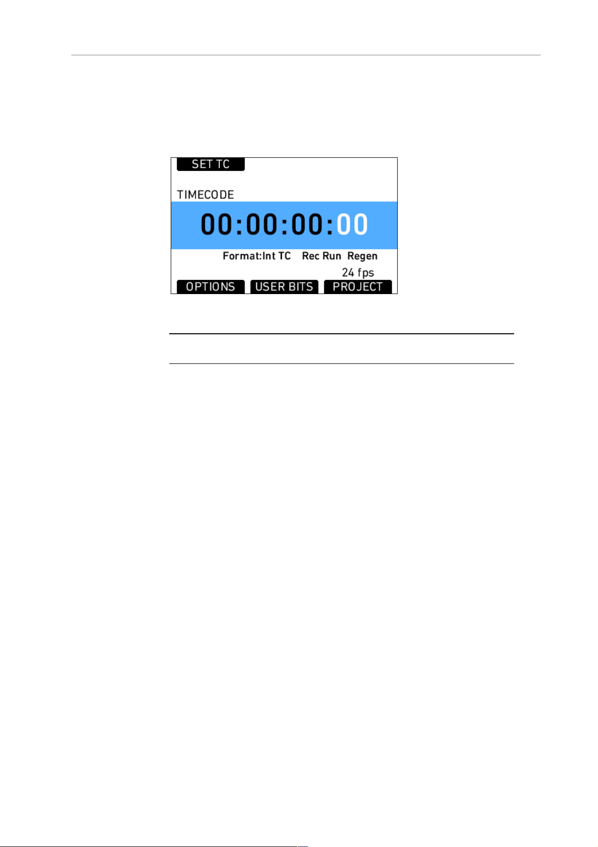
90 Camera Controls
11.1.4.1 TC
Press the TC button to open the TIMECODE screen. The TIMECODE
screen displays the current timecode and timecode format settings.
Figure 58: Timecode screen
Note: Individual frame values are not shown but are still counted.
Press the SET TC button to set the TC counter (only when the timecode
source is set to Int TC). On the SET TIMECODE screen, press the SET 2
TIME button to match the counter to the camera’s system clock. Press
the RESET button to reset counter to zero.
The PROJECT button is a quick link into the PROJECT menu screen,
where project fps can be adjusted. Project fps sets the time base of the
time code.
TIMECODE OPTIONS
Press the OPTIONS button to open the TIME CODE OPTIONS screen.
Select Source to choose the timecode source. Available sources are:
Int TC Internal TC counter
Ext LTC TC is read from the LTC input. Only possible with
Mode set to Free Run, and the project frame rate
must match the sensor frame rate.
Select Mode to define how the timecode is counted. Available modes
are:
Rec Run TC will only run while recording. The TC value
increases with every frame generated by the
sensor while recording in the project time base.
Page 91

Main Controls 91
Free Run TC runs free. If the source is set to Int TC, and the
sensor frame rate does not match the time base
of the TC, the value counts up with every new
frame generated by the sensor in the project time
base.
Select Generator to set the camera’s timecode generator. Available
generators are:
Regen Rec Run TC is regenerated from the last valid TC
value. When set to Ext LTC, the camera
continuously reads the TC signal at the LTC
connector as long as it is present. Upon
disconnection or loss of signal, the camera
continues counting on its own. When the external
signal is reconnected, the camera uses the values
of the external signal again.
When set to Int TC, the value increases with each
new frame generated by the sensor.
Jam sync Only Ext LTC can be jam sync'd. This means that
the external TC source is connected to the
camera, then the camera reads the external TC
count and continues counting on its own. The
precise crystal oscillator in the ALEXA will count
accurately for up to eight hours. After eight hours,
re-jam sync the camera to prevent timecode
offset.
The camera can be sync'd to TC signals whose
time base differs from the camera's project time
base, as long as both are integer (24, 25 and 30
fps) or non-integer (23.976 and 29.97 fps) signals.
It is not possible to mix integer and non-integer
signals.
Note: It is recommended to jam-sync after every shooting break to avoid the
risk of losing timecode sync during a shot.
Note: The camera will keep its TC for about 10 minutes after disconnection from
the power source. If a power source is connected, the camera will remember its
TC for as long as the power source is connected, even if it is switched off.
Select User bit source to set the source of the user bits. Available user
bit sources are:
Internal User bits are set manually in the User Bit
screen.
UB in Ext TC When the timecode source is set to Ext LTC,
the user bits are sampled from the external
signal.
Note: The camera will force timecode to Int TC and Regen if the sensor frame
rate does not match the project frame rate.
Page 92

92 Camera Controls
Note: Non-integer TC time base settings 23.976 and 29.97 are always counted
as non-dropframe time code.
USER BITS
Press the USER BITS screen button to access the USER BITS screen.
For each user bit, values from 0 to 9 and A to F can be set.
Press the SET UB button to start editing the user bits values.
Figure 59: USER BITS screen
Note: On HD-SDI out, the last two digits of the user bits contain the Variflag,
therefore the last two user bits cannot be set by the user.
11.1.4.2 INFO
STATUS Info
The STATUS INFO screen displays information about the current state
of the camera system. System state: Good means that all components in
the ALEXA are functioning normally. Other messages can contain error
messages prefixed with E:, or warnings prefixed with W:. For more
information about error messages and warnings, see A.4 Error
Messages and Warnings in the Appendix.
Press the SAVE TO SD button to save a system log to the SD card. This
may take up to one minute.
Note: It is only necessary to save a system log if the camera experiences
multiple error messages or other abnormal behavior. The system log is not a
human-readable file and should be sent to an ARRI Camera Service center for
analysis.
Page 93

Main Controls 93
VERSION Info
Cam serial
no.
Cam ID Translation of the camera serial number to
Firmware Version number of the currently installed camera
EVF serial
no.
EVF
firmware
The serial number of the camera.
Base36, with an additional prefix for 3D
applications. This encoding of the serial number
has been chosen so it can be part of each
filename while using the fewest number of
characters.
Software Update Packet (SUP).
The serial number of the Electronic Viewfinder
EVF-1 attached to the camera.
Version number of the Electronic Viewfinder EVF1 firmware.
Figure 60: VERSION info screen
MEDIA Info
Int. Rec.
Mode
Status Current status of internal media.
Current mode for internal recording.
Page 94
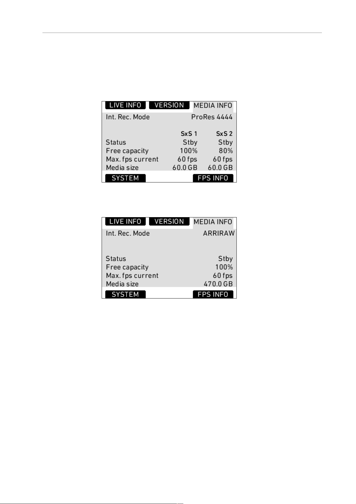
94 Camera Controls
Free
capacity
Max. fps
current
Media size Total available storage space on media
Figure 61: MEDIA INFO screen with SxS module
Free storage space displayed as a percentage.
Maximum frame rate with current codec.
Figure 62: MEDIA INFO screen with XR module
SYSTEM Info
Time/Date Current date and time. To set the date and time,
press the MENU button, select SYSTEM and select
DATE/TIME.
Fan speed Speed of the camera’s cooling fan in rotations per
minute.
Sensor
mode
Shows the active sensor mode: 16:9, 4:3 or Open
Gate.
4:3 mode is available on ALEXA Plus 4:3, ALEXA
M, ALEXA Studio, ALEXA XT, ALEXA XT Plus,
ALEXA XT M and ALEXA XT Studio. Open Gate
mode is available on ALEXA XT, ALEXA XT Plus,
ALEXA XT M and ALEXA XT Studio.
Page 95

Main Controls 95
Sensor
temperature
IP address IP address of the camera's Ethernet port.
Operating
time
Figure 63: SYSTEM info screen
Current temperature of image sensor. Target is
35°C in standard mode, 40°C in high humidity
mode.
Shows the total operating time of the camera in
hours (since first installation of SUP 4.0 or higher)
FPS Info
The FPS Info screen displays an overview of the current frame rates set
in the camera and the maximum frame rate possible on the media
loaded in the camera at the current settings.
Sensor fps Frames per second generated by the sensor
Project fps Time base the camera will use for counting
timecode and the frame rate used for on-camera
playback of internally recorded clips
REC OUT
frame rate
MON OUT
frame rate
SxS CARD
1/2/Media
max. fps
current
Frame rate output over the REC OUT HD-SDI
Frame rate output over the MON OUT HD-SDI
Maximum frame rate the loaded media can
record at the current codec.
Page 96
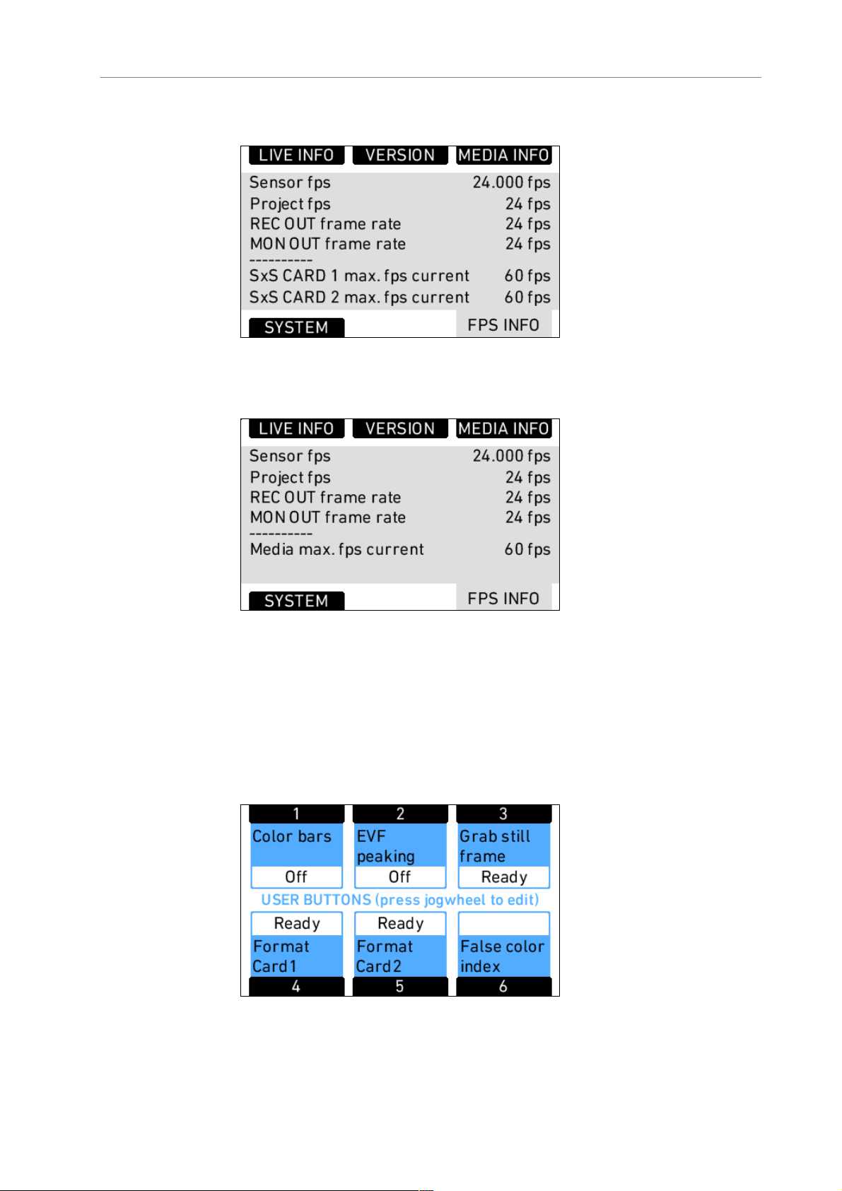
96 Camera Controls
Figure 64: FPS Info screen with SxS module
Figure 65: FPS Info screen with XR module
11.1.4.3 USER
Press the USER button to open the USER BUTTONS screen. There are
six assignable user buttons. Buttons 1, 2 and 3 are shared with User
Buttons 1, 2, and 3 in the operator controls. Press the jogwheel to see a
complete list of user button options.
Figure 66: USER BUTTONS screen
Page 97

Main Controls 97
Assign functions to the buttons by using the jogwheel.
Figure 67: Edit User Button assignment
The following table lists all available functions and if they can be
assigned to user buttons 1-3 (identical for on-screen and buttons on
camera-left side), 4-6, or both:
Name Description 1-3 4-6
None button has no function X X
MON OUT surround toggles surround view of the MON OUT
on or off
MON OUT gamma toggles gamma of MON OUT between
REC 709 and LOG C (only when recording
gamma is set to LOG C)
MON OUT look toggles the ARRI Look File on the MON
OUT on or off (only if Look File is set and
the MON OUT is set to REC 709)
MON OUT frame
lines
MON OUT status info toggles status info on the MON OUT on or
MON OUT false color toggles false color display on MON OUT
toggles frame lines on the MON OUT on
or off
off
on or off
X X
X X
X X
X X
X X
X X
MON OUT peaking toggles peaking on MON OUT on or off X X
MON anam.
desqueeze
Frame lines color toggles the color of frame lines between
toggles anamorphic desqueeze options on
MON OUT
Requires a valid Anamorphic De-squeeze
license key installed on camera
White, Red, Green, Blue, Yellow and Black
X X
X X
Page 98

98 Camera Controls
Name Description 1-3 4-6
Return in active toggles the RET IN signal on or off on the
EVF and MON OUT as set
Toggle SxS
Color bars activates color bars on MON OUT and
Phase sensor temporarily shifts the sensor framerate for
EVF surround toggles surround view on the EVF image
EVF gamma toggles gamma on the EVF between REC
toggles the active SxS slot between SxS
slots 1 and 2. SxS PRO cards must be
loaded in both.
Only on ALEXAs with SxS module
REC OUT
0.2 as long as the user button is pressed
in order to adjust the phase of the ALEXA
frame rate to an external device, i.e. a CRT
monitor or a rear screen projector.
Only available in standby and with
timecode in rec run
on or off
709 and LOG C (only when recording
gamma is set to LOG C)
X X
X X
X X
X X
X
X
EVF look toggles the ARRI Look File on the EVF on
or off (only if Look File is set and the EVF
is set to REC 709)
EVF frame lines toggles frame lines on the EVF image on
or off
EVF status info toggles status info on the EVF image on
or off
EVF zoom toggles the zoom function on the EVF X
EVF false color toggles false color display on the EVF on
or off
EVF peaking toggles peaking on the EVF on or off X
EVF anam.
desqueeze
Grab still frame takes a still frame and saves it to the SD
toggles anamorphic desqueeze options on
EVF
Requires a valid Anamorphic De-squeeze
license key installed on camera
card
Disabled in High Speed mode
X
X
X
X
X
X
Check last clip plays the last 5 seconds of the last clip,
then returns to a live image
X
Page 99

Main Controls 99
Name Description 1-3 4-6
Circle clip marks the clip as a good take or a print
during recording or playback
Auto WB Press once to open the AUTO WB sceen.
Press again to perform an automatic
white balance.
Grab GUI takes a still image of the current main
camera control screen on the LCD and
saves it to the SD card as a .png file in the
ScreenCaptures folder
Format media quick link to the Format media screen
Only on ALEXAs with XR module
Format Card 1 quick link to the Format SxS CARD 1
screen
Only on ALEXAs with SxS module
Format Card 2 quick link to the Format SxS CARD 2
screen
Only on ALEXAs with SxS module
False color index displays the FALSE COLOR INDEX screen
Mirror shutter toggles the mirror shutter between View
position, Gate position, and running
Only on ALEXA Studio
X
X
X
X
X
X
X
X
11.1.4.4 PLAY
Clips that have been recorded internally can be played back by the
camera on the EVF, MON OUT and REC OUT.
Note: The REC OUT signal cannot be used for playback when it is set to
ARRIRAW on an ALEXA with SxS module.
To play clips that have been recorded internally:
1. Press the PLAY button.
2. On the PLAY screen, the last clip recorded loads. Press the jogwheel
to play the clip.
3. Press the jogwheel to pause the clip.
4. Rotate the jogwheel to advance the clip frame by frame, or in one
second steps. Press the STEPSIZE button to toggle between
seconds and frames.
5. Press the +10% and –10% buttons to advance or rewind the clip by
ten percent of its duration.
Page 100
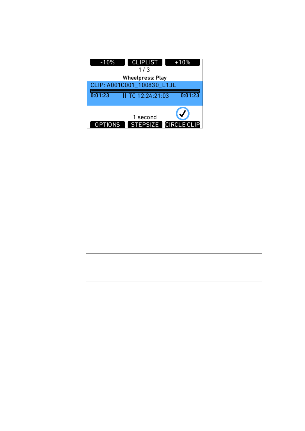
100 Camera Controls
6. Press the HOME button or BACK button to exit and output a live
image over the output paths.
Figure 68: PLAY screen
PLAY screen buttons
STEPSIZE Toggle the scrub step size between one frame and
one second.
CIRCLE
CLIP
Press to mark the clip as a circle take. This
information will be embedded in the metadata of
the clip.
+10% Advance the current clip by ten percent of the clip
duration.
-10% Rewind the current clip by ten percent of the clip
duration.
Note: Recorded clips do not contain the surround view portion of the EVF-1 or
MON OUT image. When playing back clips, the surround view portion will not
be visible.
The jogwheel can be used to scrub through the paused clip. The scrub
stepsize is shown in the lower middle section of the screen.
Additional PLAY screen information:
• clip name
• playback progress bar with current playback position in time and
total clip duration
• playback timecode
Note: Do not eject media during playback.
 Loading...