


 Loading...
Armstrong World Industries HWC PREMIER 302, HWC PREMIER 123, HWC PREMIER 183, HWC PREMIER 243, HWC PREMIER 203 User Manual
...Service Reference Manual
HWC Thru-the-Wall Units
Models:
HWC Premier 122, 182, 242, 302 123, 183, 243, 303
Copyright © 1998
Armstrong Air Conditioning Inc.
All rights reserved.
Disclaimer
This manual presents information and guidelines for proper installation, adjustment, operation and maintenance of Armstrong Magic-Pak HW/HWC Thru-the-Wall units. Read this manual before attempting assembly, installation, start-up, adjustment or operation of the unit. If you have any questions about the operation of the unit or a particular safety device, call or write Armstrong Air Conditioning Inc., 421 Monroe Street, Bellevue, Ohio USA 44811. Telephone: 419- 483-4840 Fax: 419-483-3557
The documentation and drawings contained in this manual are intended as a general guide, and may not reflect exactly the current designs, or all of the options available to our customers.
Please call or write Armstrong Air Conditioning Inc. regarding specific details of a particular furnace model, configuration or installation.
The information and specifications contained in this manual are subject to change without notice. Armstrong Air Conditioning Inc. reserves the right to change such specifications at any time without incurring obligation. Every effort has been made to ensure the accuracy of the information in this manual. For the most current information, please contact the Armstrong Customer Service Department.
This document is confidential. All information within is the sole property of Armstrong Air Conditioning Inc. and is loaned for mutual assistance. It may not be used for any purpose other than originally intended, without prior written consent of Armstrong. It is not intended for use by homeowners or as a guide for do-it-yourself projects. It provides specialized information for use by qualified service personnel, who have the proper equipment, training and experience necessary to safely install, repair, adjust and maintain the Magic-Pak units and components described within.
SRM-HW/HWC 8/99

|
Service Reference Manual |
TABLE OF CONTENTS |
|
|
||
|
|
TABLE OF CONTENTS |
|
|||
|
|
|
||||
|
|
1 |
- Specifications |
|
||
|
|
2 |
- Sequence of Operations |
|
||
|
|
3 |
- Unit Tear Down |
|
||
|
|
4 |
- Component Location Illustrations |
|
||
|
|
5 |
- Unit Components |
|
||
|
|
6 |
- Installation |
|
||
|
|
7 |
- Accessories |
|
||
|
|
8 |
- Parts Lists |
|
||
|
|
9 |
- Troubleshooting/Performance/ |
|
||
|
|
|
Charge Weights |
|
||
|
Go to: |
If you need information on: |
|
|||
|
|
|
|
|
||
|
Section 1 |
Performance, electrical data and cabinet dimensions. |
|
|||
|
Section 2 |
Sequence of operation descriptions with accompanying schematics. |
|
|||
|
Section 3 |
Complete description of unit disassembly. |
|
|||
|
Section 4 |
Locations of major components of HW/HWC models. |
|
|||
|
Section 5 |
Illustrations and specifications for individual components including valves, |
|
|||
|
|
blowers, ignition controls and blower control boards. |
|
|||
|
Section 6 |
Installation requirements and startup guidelines. |
|
|||
|
Section 7 |
Complete listing of all Armstrong accessories available, including wall |
|
|||
|
|
sleeves, louvers and gas conversion kits. |
|
|||
|
Section 8 |
Complete service parts lists for all HW and HWC models. |
|
|||
|
Section 9 |
System check and troubleshooting procedures. |
|
|||
SRM-HW/HWC 8/99

Service Reference Manual |
SPECIFICATIONS |
1-1
Section 1 - Specifications
Models Covered By This Manual ............ |
1-2 |
Model Number Guide ............................ |
1-2 |
Product Serial Numbers |
|
(Beginning 1993) ................................. |
1-2 |
Summary of Model Revisions/Variations 1-3 |
|
Heating Configuration Table ........................ |
1-3 |
Cooling Configuration Table ......................... |
1-3 |
HW/HWC ............................................ |
1-4 |
Physical and Electrical ................................ |
1-4 |
Performance Ratings .................................. |
1-4 |
Blower Performance ................................... |
1-6 |
Dimensions ................................................ |
1-6 |
Wall Sleeve................................................ |
1-7 |
SRM-HW/HWC 8/99

SPECIFICATIONS |
Magic-Pak: HW/HWC |
1-2
Models Covered By This Manual
HWC Gas Heating/Electric Cooling Units
HW122, 123
HW182,183
HW242, 243
HW302, 303
HW Gas Heating Only Units
26HW
38HW
51HW
64HW
Model Number Guide
HW/HWC Models |
26 H W C 12 2 -- 2A |
|
|
26 = Rated Input BTU/Hr x 1000
H = Gas Heat
W = Thru-the-Wall
C = Cooling
12 = Nominal Cooling BTU/Hr x 1000
2 = Cooling Efficiency 2 - 9.7 SEER
2A = Revision Code
Product Serial Numbers, Beginning 1993
84 |
95 |
A |
12345 |
84 = Armstrong Factory Number
95 = Year (ex: 1995)
A = Month (see list below)
12345 = Sequential Number
A = Jan |
B = Feb |
C = Mar |
D = Apr |
E = May |
F = June |
G = July |
H = Aug |
J = Sept |
K = Oct |
L = Nov |
M = Dec |
HW/HWC-SRM
8/99

Service Reference Manual |
SPECIFICATIONS |
1-3
Summary of Model Revisions/Variations
Table 1-1 Heating Configurations of HW/HWC Units
Model |
Configuration |
AFUE |
Ignition/Blower Control |
Ignition |
|
Type |
|||||
|
|
|
|
||
|
|
|
|
|
|
(All) HWC (123, 183, 243, 303) -1 |
Gas Heat/ |
80 |
UTech Combination Ignition/Blower Control 1097 |
DSI |
|
Electric Cool |
|||||
|
|
|
|
||
|
|
|
|
|
|
(All) HW -9 |
Gas Heat Only |
80 |
UTech Combination Ignition/Blower Control 1097 |
DSI |
|
|
|
|
|
|
|
(All) HWC (122, 182, 242, 302) |
Gas Heat/ |
|
Ignition Control: Fenwal Triton 2461D |
|
|
80 |
Blower Control: Heatcraft IBCH4C401, |
DSI |
|||
-11, -10, -9, -8, -7, -6, -5 |
Electric Cool |
||||
|
Tridelta 920B0048 or UTech 1010 |
|
|||
|
|
|
|
||
|
|
|
|
|
|
(All) HWC (122, 182, 242, 302) |
Gas Heat/ |
|
Ignition Control: Fenwal 05-29 |
|
|
80 |
Blower Control: Heatcraft IBCH4C401, |
DSI |
|||
-4, -3, -2, -1 |
Electric Cool |
||||
|
Tridelta 920B0048 or UTech 1010 |
|
|||
|
|
|
|
||
|
|
|
|
|
Table 1-2 Cooling Configurations of HWC Units
Model |
Configuration |
Tonnage |
SEER |
Compressor Type* |
Metering Device |
|
|
|
|
|
|
|
|
(All) HWC 123-1 |
Gas Heat/Electric Cool |
1 |
9.7 |
Tecumseh Rotary |
Capillary Tube/Filter Drier |
|
|
|
|
|
|
|
|
(All) HWC183-1 |
Gas Heat/Electric Cool |
1.5 |
9.7 |
Tecumseh |
Capillary Tube/Filter Drier |
|
Reciprocating |
||||||
|
|
|
|
|
||
|
|
|
|
|
|
|
(All) HWC 243-1 |
Gas Heat/Electric Cool |
2 |
9.7 |
Copeland Scroll |
Capillary Tube/Filter Drier |
|
|
|
|
|
|
|
|
(All) HWC 303-1 |
Gas HeatElectric Cool |
2.5 |
9.7 |
Copeland Scroll |
Capillary Tube/Filter Drier |
|
|
|
|
|
|
|
|
(All) HWC 182-11, - |
Gas Heat/Electric Cool |
1.5 |
9.7 |
Tecumseh |
Capillary Tube/Filter Drier |
|
9, -7, -6 |
Reciprocating |
|||||
|
|
|
|
|||
|
|
|
|
|
|
|
(All) HWC 242-11, -9 |
Gas Heat/Electric Cool |
2 |
9.7 |
Copeland Scroll |
Capillary Tube/Filter Drier |
|
|
|
|
|
|
|
|
(All) HWC 122-10, - |
Gas Heat/Electric Cool |
1 |
9.7 |
Tecumseh Rotary |
Capillary Tube/Filter Drier |
|
8, -5, -4, -3, -1 |
||||||
|
|
|
|
|
||
|
|
|
|
|
|
|
(All) HWC 242-10, - |
Gas Heat/Electric Cool |
2 |
9.7 |
Copeland Scroll |
Capillary Tube/Filter Drier |
|
8, -5, -4, -3, -1 |
||||||
|
|
|
|
|
||
|
|
|
|
|
|
|
(All) HWC 302-9 |
Gas Heat/Electric Cool |
2.5 |
9.5 |
Copeland Scroll |
Capillary Tube/Filter Drier |
|
|
|
|
|
|
|
|
(All) HWC 182-8, -5, |
Gas Heat/Electric Cool |
1.5 |
9.7 |
Tecumseh Rotary |
Capillary Tube/Filter Drier |
|
-4, -3, -2 |
||||||
|
|
|
|
|
||
|
|
|
|
|
|
|
(All) HWC 302-8, -5, |
Gas Heat/Electric Cool |
2.5 |
9.5 |
Copeland Scroll |
Capillary Tube/Filter Drier |
|
-4, -3, -1 |
||||||
|
|
|
|
|
||
|
|
|
|
|
|
|
(All) HWC 182-1 |
Gas Heat/Electric Cool |
1.5 |
9.5 |
Copeland Scroll |
Capillary Tube/Filter Drier |
|
|
|
|
|
|
|
* For more information on the compressors used in HWC units, see the Unit Components section, beginning on page 5-28.
SRM-HW/HWC 8/99

SPECIFICATIONS |
Magic-Pak: HW/HWC |
1-4
HW/HWC
Physical and Electrical
Table 1-3 |
Physical and Electrical Specifications - HWC Units |
|
|
|
|
|
|||||||||
|
|
|
|
|
|
|
|
|
|
|
|
|
|
|
|
|
|
|
|
Max. |
Comp. |
Comp. |
O.D. |
|
Outside |
|
Indoor |
|
|
|
|
|
|
Normal |
Min. |
|
Fan |
|
Wheel |
Blower |
Refrig. |
|
|||||
|
Voltage/ |
Fuse/HACR |
Rated |
Locked |
Fan |
Nom. |
Rated |
Weight |
|||||||
Model |
Voltage |
Circuit |
Rated |
dia. x |
Rated |
Charge |
|||||||||
Hz/Phase |
Brkr. |
Load |
Rotor |
Dia. |
RPM |
HP |
(lbs.) |
||||||||
|
Range |
Ampacity |
Load |
width |
HP |
(oz.) |
|||||||||
|
|
(amps) |
(amps) |
(amps) |
(in.) |
|
|
|
|||||||
|
|
|
|
|
(amps) |
|
(in.) |
|
|
|
|||||
|
|
|
|
|
|
|
|
|
|
|
|
|
|||
|
|
|
|
|
|
|
|
|
|
|
|
|
|
|
|
26HWC122/123 |
208-230/60/1 |
197-253 |
8.3 |
15 |
5.0 |
26.3 |
18 |
1075 |
0.9 |
1/8 |
10 X 4 |
1/6 |
42 |
325 |
|
|
|
|
|
|
|
|
|
|
|
|
|
|
|
|
|
38HWC122/123 |
208-230/60/1 |
197-253 |
8.3 |
15 |
5.0 |
26.3 |
18 |
1075 |
0.9 |
1/8 |
10 X 4 |
1/6 |
42 |
325 |
|
|
|
|
|
|
|
|
|
|
|
|
|
|
|
|
|
38HWC182/183 |
208-230/60/1 |
197-253 |
13.6 |
20 |
8.3 |
45.0 |
18 |
1075 |
0.9 |
1/8 |
10 X 4 |
1/3 |
56 |
350 |
|
|
|
|
|
|
|
|
|
|
|
|
|
|
|
|
|
51HWC182/183 |
208-230/60/1 |
197-253 |
13.6 |
20 |
8.3 |
45.0 |
18 |
1075 |
0.9 |
1/8 |
10 X 4 |
1/3 |
56 |
350 |
|
|
|
|
|
|
|
|
|
|
|
|
|
|
|
|
|
64HWC182/183 |
208-230/60/1 |
197-253 |
13.6 |
20 |
8.3 |
45.0 |
18 |
1075 |
0.9 |
1/8 |
10 X 4 |
1/3 |
56 |
350 |
|
|
|
|
|
|
|
|
|
|
|
|
|
|
|
|
|
36HWC242/243 |
208-230/60/1 |
197-253 |
18.6 |
25 |
11.6 |
62.5 |
18 |
1075 |
1.8 |
1/4 |
10 X 4 |
1/3 |
58 |
360 |
|
|
|
|
|
|
|
|
|
|
|
|
|
|
|
|
|
51HWC242/243 |
208-230/60/1 |
197-253 |
18.6 |
25 |
11.6 |
62.5 |
18 |
1075 |
1.8 |
1/4 |
10 X 4 |
1/3 |
58 |
360 |
|
|
|
|
|
|
|
|
|
|
|
|
|
|
|
|
|
64HWC242/243 |
208-230/60/1 |
197-253 |
18.6 |
25 |
11.6 |
62.5 |
18 |
1075 |
1.8 |
1/4 |
10 X 4 |
1/3 |
58 |
360 |
|
|
|
|
|
|
|
|
|
|
|
|
|
|
|
|
|
51HWC302 |
208-230/60/1 |
197-253 |
22.4 |
30 |
14.6 |
76.0 |
18 |
1075 |
1.8 |
1/4 |
10 X 4 |
1/3 |
59 |
380 |
|
|
|
|
|
|
|
|
|
|
|
|
|
|
|
|
|
64HWC302 |
208-230/60/1 |
197-253 |
22.4 |
30 |
14.6 |
76.0 |
18 |
1075 |
1.8 |
1/4 |
10 X 4 |
1/3 |
59 |
380 |
|
|
|
|
|
|
|
|
|
|
|
|
|
|
|
|
|
51HWC303 |
208-230/60/1 |
197-253 |
21.9 |
30 |
14.1 |
73.0 |
18 |
1075 |
1.8 |
1/4 |
10 X 4 |
1/3 |
59 |
380 |
|
|
|
|
|
|
|
|
|
|
|
|
|
|
|
|
|
64HWC303 |
208-230/60/1 |
197-253 |
21.9 |
30 |
14.1 |
73.0 |
18 |
1075 |
1.8 |
1/4 |
10 X 4 |
1/3 |
59 |
380 |
|
|
|
|
|
|
|
|
|
|
|
|
|
|
|
|
|
Performance Ratings
Table 1-4 |
Performance Ratings - HWC122/123 |
|
|
|
|
|
|
|
|
|
|
|||||||||||
|
|
|
|
|
|
|
|
|
|
|
|
|
|
|
|
|
|
|
|
|
|
|
|
|
|
|
|
|
|
|
|
|
Outdoor Air Temperature Entering Outdoor Coil |
|
|
|
|
|
|
|
|||||
|
|
|
|
|
|
|
|
|
|
|
|
|
|
|
|
|
|
|
|
|
|
|
|
|
|
|
|
85° |
|
|
|
|
95° |
|
|
|
|
105° |
|
|
|
|
115° |
|
|
|
|
|
|
|
|
|
|
|
|
|
|
|
|
|
|
|
|
|
|
|
|
|
Enter. |
Total |
|
Total |
Comp. |
S/T at |
S/T at |
S/T at |
Total |
Comp. |
S/T at |
S/T at |
S/T at |
Total |
Comp. |
S/T at |
S/T at |
S/T at |
Total |
Comp. |
S/T at |
S/T at |
S/T at |
Air |
|
Cooling |
75° |
80° |
85° |
Cooling |
75° |
80° |
85° |
Cooling |
75° |
80° |
85° |
Cooling |
75° |
80° |
85° |
|||||
Wet |
|
Watts |
Watts |
Watts |
Watts |
|||||||||||||||||
Vol. |
|
Capacity |
Dry |
Dry |
Dry |
Capacity |
Dry |
Dry |
Dry |
Capacity |
Dry |
Dry |
Dry |
Capacity |
Dry |
Dry |
Dry |
|||||
Bulb |
|
Input |
Input |
Input |
Input |
|||||||||||||||||
(CFM) |
|
(Btuh) |
Bulb |
Bulb |
Bulb |
(Btuh) |
Bulb |
Bulb |
Bulb |
(Btuh) |
Bulb |
Bulb |
Bulb |
(Btuh) |
Bulb |
Bulb |
Bulb |
|||||
|
|
|
|
|
|
|||||||||||||||||
|
|
|
|
|
|
|
|
|
|
|
|
|
|
|
|
|
|
|
|
|
|
|
|
400 |
|
12600 |
820 |
.78 |
.92 |
1.00 |
12000 |
910 |
.80 |
.95 |
1.00 |
11400 |
1000 |
.82 |
.95 |
1.00 |
10800 |
1090 |
.85 |
1.00 |
1.00 |
63° |
|
|
|
|
|
|
|
|
|
|
|
|
|
|
|
|
|
|
|
|
|
|
450 |
|
12800 |
820 |
.82 |
.97 |
1.00 |
12200 |
910 |
.85 |
1.00 |
1.00 |
11600 |
1000 |
.87 |
1.00 |
1.00 |
11000 |
1090 |
.90 |
1.00 |
1.00 |
|
|
|
|
|
|
|
|
|
|
|
|
|
|
|
|
|
|
|
|
|
|
|
|
|
500 |
|
13100 |
820 |
.87 |
1.00 |
1.00 |
12400 |
910 |
.90 |
1.00 |
1.00 |
11800 |
1000 |
.92 |
1.00 |
1.00 |
11200 |
1090 |
.95 |
1.00 |
1.00 |
|
|
|
|
|
|
|
|
|
|
|
|
|
|
|
|
|
|
|
|
|
|
|
|
400 |
|
13400 |
820 |
.59 |
.74 |
.89 |
12700 |
910 |
.60 |
.76 |
.91 |
12100 |
1010 |
.62 |
.79 |
1.00 |
11500 |
1110 |
.63 |
.81 |
.96 |
67° |
|
|
|
|
|
|
|
|
|
|
|
|
|
|
|
|
|
|
|
|
|
|
450 |
|
13600 |
820 |
.62 |
.78 |
.94 |
12900 |
910 |
.64 |
.80 |
.97 |
12300 |
1010 |
.65 |
.83 |
1.00 |
11700 |
1110 |
.67 |
.86 |
1.00 |
|
|
|
|
|
|
|
|
|
|
|
|
|
|
|
|
|
|
|
|
|
|
|
|
|
500 |
|
13900 |
820 |
.65 |
.82 |
.99 |
13200 |
910 |
.67 |
.84 |
1.00 |
12600 |
1010 |
.69 |
.88 |
1.00 |
11900 |
1110 |
.70 |
.91 |
1.00 |
|
|
|
|
|
|
|
|
|
|
|
|
|
|
|
|
|
|
|
|
|
|
|
|
400 |
|
14200 |
830 |
.40 |
.56 |
.72 |
13500 |
920 |
.40 |
.57 |
.74 |
12800 |
1020 |
.41 |
.58 |
.76 |
12100 |
1120 |
.41 |
.59 |
.78 |
71° |
|
|
|
|
|
|
|
|
|
|
|
|
|
|
|
|
|
|
|
|
|
|
450 |
|
14400 |
830 |
.42 |
.59 |
.76 |
13700 |
920 |
.42 |
.60 |
.78 |
13000 |
1020 |
.43 |
.62 |
.80 |
12300 |
1120 |
.43 |
.63 |
.82 |
|
|
|
|
|
|
|
|
|
|
|
|
|
|
|
|
|
|
|
|
|
|
|
|
|
500 |
|
14700 |
830 |
.44 |
.62 |
.80 |
14000 |
920 |
.44 |
.63 |
.82 |
13300 |
1020 |
.45 |
.65 |
.84 |
12600 |
1120 |
.45 |
.66 |
.87 |
|
|
|
|
|
|
|
|
|
|
|
|
|
|
|
|
|
|
|
|
|
|
|
Note: All values are gross capacities and do not include blower motor heat deduction.
HW/HWC-SRM
8/99

SRM-HW/HWC 8/99
Service Reference Manual |
SPECIFICATIONS |
1-5
Performance Ratings (continued)
Table 1-5 |
Performance Ratings - HWC182/183 |
|
|
|
|
|
|
|
|
|
|
|||||||||||
|
|
|
|
|
|
|
|
|
|
|
|
|
|
|
|
|
|
|
|
|
|
|
|
|
|
|
|
|
|
|
|
|
Outdoor Air Temperature Entering Outdoor Coil |
|
|
|
|
|
|
|
|||||
|
|
|
|
|
|
|
|
|
|
|
|
|
|
|
|
|
|
|
|
|
|
|
|
|
|
|
|
85° |
|
|
|
|
95° |
|
|
|
|
105° |
|
|
|
|
115° |
|
|
|
|
|
|
|
|
|
|
|
|
|
|
|
|
|
|
|
|
|
|
|
|
|
Enter. |
Total |
|
Total |
Comp. |
S/T at |
S/T at |
S/T at |
Total |
Comp. |
S/T at |
S/T at |
S/T at |
Total |
Comp. |
S/T at |
S/T at |
S/T at |
Total |
Comp. |
S/T at |
S/T at |
S/T at |
Air |
|
Cooling |
75° |
80° |
85° |
Cooling |
75° |
80° |
85° |
Cooling |
75° |
80° |
85° |
Cooling |
75° |
80° |
85° |
|||||
Wet |
|
Watts |
Watts |
Watts |
Watts |
|||||||||||||||||
Vol. |
|
Capacity |
Dry |
Dry |
Dry |
Capacity |
Dry |
Dry |
Dry |
Capacity |
Dry |
Dry |
Dry |
Capacity |
Dry |
Dry |
Dry |
|||||
Bulb |
|
Input |
Input |
Input |
Input |
|||||||||||||||||
(CFM) |
|
(Btuh) |
Bulb |
Bulb |
Bulb |
(Btuh) |
Bulb |
Bulb |
Bulb |
(Btuh) |
Bulb |
Bulb |
Bulb |
(Btuh) |
Bulb |
Bulb |
Bulb |
|||||
|
|
|
|
|
|
|||||||||||||||||
|
|
|
|
|
|
|
|
|
|
|
|
|
|
|
|
|
|
|
|
|
|
|
|
550 |
|
18400 |
1370 |
.75 |
.90 |
1.00 |
17100 |
1470 |
.78 |
.92 |
1.00 |
15700 |
1550 |
.82 |
.96 |
1.00 |
14400 |
1640 |
.86 |
.96 |
1.00 |
63° |
|
|
|
|
|
|
|
|
|
|
|
|
|
|
|
|
|
|
|
|
|
|
600 |
|
18700 |
1380 |
.78 |
.93 |
1.00 |
17400 |
1480 |
.81 |
.96 |
1.00 |
16000 |
1560 |
.85 |
1.00 |
1.00 |
14600 |
1650 |
.89 |
1.00 |
1.00 |
|
|
|
|
|
|
|
|
|
|
|
|
|
|
|
|
|
|
|
|
|
|
|
|
|
650 |
|
18900 |
1390 |
.81 |
.96 |
1.00 |
17600 |
1490 |
.84 |
.99 |
1.00 |
16200 |
1570 |
.88 |
1.00 |
1.00 |
14800 |
1660 |
.92 |
1.00 |
1.00 |
|
550 |
|
19800 |
1410 |
.58 |
.72 |
.87 |
18500 |
1510 |
.59 |
.74 |
.89 |
17100 |
1600 |
.62 |
.78 |
.94 |
15600 |
1700 |
.64 |
.80 |
.96 |
67° |
|
|
|
|
|
|
|
|
|
|
|
|
|
|
|
|
|
|
|
|
|
|
600 |
|
20100 |
1420 |
.60 |
.75 |
.90 |
18800 |
1520 |
.62 |
.77 |
.93 |
17400 |
1610 |
.64 |
.81 |
.98 |
15900 |
1710 |
.66 |
.83 |
1.00 |
|
|
|
|
|
|
|
|
|
|
|
|
|
|
|
|
|
|
|
|
|
|
|
|
|
650 |
|
20400 |
1430 |
.62 |
.78 |
.93 |
19000 |
1530 |
.64 |
.80 |
.96 |
17600 |
1620 |
.66 |
.84 |
1.00 |
16100 |
1720 |
.68 |
.86 |
1.00 |
|
|
|
|
|
|
|
|
|
|
|
|
|
|
|
|
|
|
|
|
|
|
|
|
550 |
|
21200 |
1450 |
.40 |
.55 |
.69 |
19700 |
1550 |
.40 |
.56 |
.72 |
18300 |
1650 |
.41 |
.58 |
.75 |
16700 |
1750 |
.41 |
.60 |
.78 |
71° |
|
|
|
|
|
|
|
|
|
|
|
|
|
|
|
|
|
|
|
|
|
|
600 |
|
21500 |
1460 |
.42 |
.57 |
.72 |
20000 |
1560 |
.42 |
.59 |
.75 |
18600 |
1660 |
.43 |
.61 |
.78 |
17000 |
1760 |
.43 |
.62 |
.81 |
|
|
|
|||||||||||||||||||||
|
|
|
|
|
|
|
|
|
|
|
|
|
|
|
|
|
|
|
|
|
|
|
|
650 |
|
21800 |
1470 |
.43 |
.59 |
.74 |
20300 |
1570 |
.43 |
.60 |
.78 |
18800 |
1670 |
.44 |
.63 |
.81 |
17200 |
1770 |
.44 |
.64 |
.84 |
|
|
|
|
|
|
|
|
|
|
|
|
|
|
|
|
|
|
|
|
|
|
|
Note: All values are gross capacities and do not include blower motor heat deduction.
Table 1-6 |
Performance Ratings - HWC242/243 |
|
|
|
|
|
|
|
|
|
|
|||||||||||
|
|
|
|
|
|
|
|
|
|
|
|
|
|
|
|
|
|
|
|
|
|
|
|
|
|
|
|
|
|
|
|
|
Outdoor Air Temperature Entering Outdoor Coil |
|
|
|
|
|
|
|
|||||
|
|
|
|
|
|
|
|
|
|
|
|
|
|
|
|
|
|
|
|
|
|
|
|
|
|
|
|
85° |
|
|
|
|
95° |
|
|
|
|
105° |
|
|
|
|
115° |
|
|
|
|
|
|
|
|
|
|
|
|
|
|
|
|
|
|
|
|
|
|
|
|
|
Enter. |
Total |
|
Total |
Comp. |
S/T at |
S/T at |
S/T at |
Total |
Comp. |
S/T at |
S/T at |
S/T at |
Total |
Comp. |
S/T at |
S/T at |
S/T at |
Total |
Comp. |
S/T at |
S/T at |
S/T at |
Air |
|
Cooling |
75° |
80° |
85° |
Cooling |
75° |
80° |
85° |
Cooling |
75° |
80° |
85° |
Cooling |
75° |
80° |
85° |
|||||
Wet |
|
Watts |
Watts |
Watts |
Watts |
|||||||||||||||||
Vol. |
|
Capacity |
Dry |
Dry |
Dry |
Capacity |
Dry |
Dry |
Dry |
Capacity |
Dry |
Dry |
Dry |
Capacity |
Dry |
Dry |
Dry |
|||||
Bulb |
|
Input |
Input |
Input |
Input |
|||||||||||||||||
(CFM) |
|
(Btuh) |
Bulb |
Bulb |
Bulb |
(Btuh) |
Bulb |
Bulb |
Bulb |
(Btuh) |
Bulb |
Bulb |
Bulb |
(Btuh) |
Bulb |
Bulb |
Bulb |
|||||
|
|
|
|
|
|
|||||||||||||||||
|
|
|
|
|
|
|
|
|
|
|
|
|
|
|
|
|
|
|
|
|
|
|
|
700 |
|
24300 |
1870 |
.74 |
.88 |
1.00 |
23200 |
2110 |
.76 |
.89 |
1.00 |
21800 |
2380 |
.78 |
.94 |
1.00 |
21000 |
2710 |
.80 |
.95 |
1.00 |
63° |
|
|
|
|
|
|
|
|
|
|
|
|
|
|
|
|
|
|
|
|
|
|
800 |
|
24700 |
1870 |
.78 |
.93 |
1.00 |
23600 |
2110 |
.80 |
.94 |
1.00 |
22200 |
2380 |
.82 |
.99 |
1.00 |
21300 |
2710 |
.84 |
1.00 |
1.00 |
|
|
|
|
|
|
|
|
|
|
|
|
|
|
|
|
|
|
|
|
|
|
|
|
|
900 |
|
25200 |
1880 |
.82 |
.98 |
1.00 |
24100 |
2120 |
.85 |
.99 |
1.00 |
22600 |
2390 |
.87 |
1.00 |
1.00 |
21700 |
2720 |
.89 |
1.00 |
1.00 |
|
|
|
|
|
|
|
|
|
|
|
|
|
|
|
|
|
|
|
|
|
|
|
|
700 |
|
25900 |
1890 |
.57 |
.71 |
.85 |
24700 |
2130 |
.58 |
.72 |
.86 |
23600 |
2400 |
.59 |
.75 |
.91 |
22400 |
2750 |
.60 |
.76 |
.92 |
67° |
|
|
|
|
|
|
|
|
|
|
|
|
|
|
|
|
|
|
|
|
|
|
800 |
|
26300 |
1890 |
.60 |
.75 |
.90 |
25100 |
2130 |
.61 |
.76 |
.91 |
24000 |
2400 |
.62 |
.79 |
.96 |
22800 |
2750 |
.63 |
.80 |
.97 |
|
|
|
|
|
|
|
|
|
|
|
|
|
|
|
|
|
|
|
|
|
|
|
|
|
900 |
|
26800 |
1900 |
.63 |
.79 |
.95 |
25600 |
2140 |
.64 |
.80 |
.96 |
24500 |
2410 |
.66 |
.84 |
1.00 |
23200 |
2760 |
.67 |
.85 |
1.00 |
|
|
|
|
|
|
|
|
|
|
|
|
|
|
|
|
|
|
|
|
|
|
|
|
700 |
|
27300 |
1910 |
.40 |
.55 |
.69 |
26100 |
2150 |
.40 |
.55 |
.70 |
24900 |
2430 |
.40 |
.56 |
.72 |
23700 |
2770 |
.40 |
.57 |
.74 |
71° |
|
|
|
|
|
|
|
|
|
|
|
|
|
|
|
|
|
|
|
|
|
|
800 |
|
27700 |
1910 |
.42 |
.58 |
.73 |
26500 |
2150 |
.42 |
.58 |
.74 |
25300 |
2430 |
.42 |
.59 |
.76 |
24100 |
2770 |
.42 |
.60 |
.78 |
|
|
|
|
|
|
|
|
|
|
|
|
|
|
|
|
|
|
|
|
|
|
|
|
|
900 |
|
28300 |
1920 |
.44 |
.61 |
.77 |
27000 |
2160 |
.44 |
.61 |
.78 |
25800 |
2440 |
.44 |
.62 |
.80 |
24600 |
2780 |
.44 |
.63 |
.82 |
|
|
|
|
|
|
|
|
|
|
|
|
|
|
|
|
|
|
|
|
|
|
|
Note: All values are gross capacities and do not include blower motor heat deduction.
Table 1-7 |
Performance Ratings - HWC302/303 |
|
|
|
|
|
|
|
|
|
|
|||||||||||
|
|
|
|
|
|
|
|
|
|
|
|
|
|
|
|
|
|
|
|
|
|
|
|
|
|
|
|
|
|
|
|
|
Outdoor Air Temperature Entering Outdoor Coil |
|
|
|
|
|
|
|
|||||
|
|
|
|
|
|
|
|
|
|
|
|
|
|
|
|
|
|
|
|
|
|
|
|
|
|
|
|
85° |
|
|
|
|
95° |
|
|
|
|
105° |
|
|
|
|
115° |
|
|
|
|
|
|
|
|
|
|
|
|
|
|
|
|
|
|
|
|
|
|
|
|
|
Enter. |
Total |
|
Total |
Comp. |
S/T at |
S/T at |
S/T at |
Total |
Comp. |
S/T at |
S/T at |
S/T at |
Total |
Comp. |
S/T at |
S/T at |
S/T at |
Total |
Comp. |
S/T at |
S/T at |
S/T at |
Air |
|
Cooling |
75° |
80° |
85° |
Cooling |
75° |
80° |
85° |
Cooling |
75° |
80° |
85° |
Cooling |
75° |
80° |
85° |
|||||
Wet |
|
Watts |
Watts |
Watts |
Watts |
|||||||||||||||||
Vol. |
|
Capacity |
Dry |
Dry |
Dry |
Capacity |
Dry |
Dry |
Dry |
Capacity |
Dry |
Dry |
Dry |
Capacity |
Dry |
Dry |
Dry |
|||||
Bulb |
|
Input |
Input |
Input |
Input |
|||||||||||||||||
(CFM) |
|
(Btuh) |
Bulb |
Bulb |
Bulb |
(Btuh) |
Bulb |
Bulb |
Bulb |
(Btuh) |
Bulb |
Bulb |
Bulb |
(Btuh) |
Bulb |
Bulb |
Bulb |
|||||
|
|
|
|
|
|
|||||||||||||||||
|
|
|
|
|
|
|
|
|
|
|
|
|
|
|
|
|
|
|
|
|
|
|
|
775 |
|
28500 |
2150 |
.72 |
.84 |
.97 |
27300 |
2390 |
.73 |
.87 |
1.00 |
26100 |
2670 |
.74 |
.89 |
1.00 |
24800 |
2990 |
.76 |
.90 |
1.00 |
63° |
|
|
|
|
|
|
|
|
|
|
|
|
|
|
|
|
|
|
|
|
|
|
850 |
|
28900 |
2160 |
.74 |
.87 |
1.00 |
27600 |
2400 |
.76 |
.90 |
1.00 |
26400 |
2680 |
.77 |
.93 |
1.00 |
25100 |
3000 |
79 |
.93 |
1.00 |
|
|
|
|
|
|
|
|
|
|
|
|
|
|
|
|
|
|
|
|
|
|
|
|
|
925 |
|
29300 |
2170 |
.77 |
.90 |
1.00 |
28000 |
2410 |
.79 |
.93 |
1.00 |
26800 |
2690 |
.80 |
.96 |
1.00 |
25400 |
3010 |
.82 |
.96 |
1.00 |
|
|
|
|
|
|
|
|
|
|
|
|
|
|
|
|
|
|
|
|
|
|
|
|
775 |
|
30400 |
2190 |
.56 |
.69 |
.82 |
29000 |
2440 |
.57 |
.71 |
.84 |
27800 |
2720 |
.58 |
.73 |
.88 |
26400 |
3050 |
.59 |
.73 |
.88 |
67° |
|
|
|
|
|
|
|
|
|
|
|
|
|
|
|
|
|
|
|
|
|
|
850 |
|
30800 |
2200 |
.58 |
.71 |
.85 |
29400 |
2450 |
.59 |
.73 |
.87 |
28100 |
2730 |
.60 |
.75 |
.91 |
26700 |
3060 |
.61 |
.76 |
.91 |
|
|
|
|
|
|
|
|
|
|
|
|
|
|
|
|
|
|
|
|
|
|
|
|
|
925 |
|
31200 |
2210 |
.60 |
.73 |
.87 |
29800 |
2460 |
.61 |
.76 |
.90 |
28500 |
2740 |
.62 |
.78 |
.94 |
27100 |
3070 |
.63 |
.79 |
.94 |
|
|
|
|
|
|
|
|
|
|
|
|
|
|
|
|
|
|
|
|
|
|
|
|
775 |
|
32200 |
2220 |
.40 |
.54 |
.68 |
30800 |
2480 |
.41 |
.55 |
.69 |
29300 |
2760 |
.41 |
.56 |
.71 |
28000 |
3090 |
.42 |
.57 |
.73 |
71° |
|
|
|
|
|
|
|
|
|
|
|
|
|
|
|
|
|
|
|
|
|
|
850 |
|
32600 |
2230 |
.41 |
.56 |
.70 |
31200 |
2490 |
.42 |
.57 |
.71 |
29700 |
2770 |
.42 |
.58 |
.73 |
28300 |
3100 |
.43 |
.59 |
.75 |
|
|
|
|
|
|
|
|
|
|
|
|
|
|
|
|
|
|
|
|
|
|
|
|
|
925 |
|
33000 |
2240 |
.42 |
.57 |
.72 |
31600 |
2500 |
.43 |
.58 |
.73 |
30100 |
2780 |
.43 |
.60 |
.76 |
28700 |
3110 |
.45 |
.61 |
.78 |
|
|
|
|
|
|
|
|
|
|
|
|
|
|
|
|
|
|
|
|
|
|
|
Note: All values are gross capacities and do not include blower motor heat deduction.
|
|
SPECIFICATIONS |
|
|
|
Magic-Pak: HW/HWC |
|||||
1-6 |
|
|
|
||||||||
|
Blower Performance |
|
|
|
|
|
|
|
|||
|
|
|
|
|
|
|
|
|
|||
|
|
|
|
|
|
|
|
||||
|
|
Table 1-8 Blower Performance - HWC Units |
|
|
|
|
|||||
|
|
|
|
|
|
|
|
|
|
|
|
|
|
Model |
Blower Speed |
|
|
CFM @ ext. static pressure - in. w.c. with filter(s) |
|
|
|||
|
|
|
|
|
|
|
|
|
|
||
|
|
|
|
|
0.2 |
|
0.3 |
0.4 |
|
0.5 |
|
|
|
|
|
|
|
|
|
|
|
|
|
|
|
|
Hi |
|
650 |
|
615 |
575 |
|
540 |
|
|
|
HWC122/123 |
|
|
|
|
|
|
|
|
|
|
|
Med |
|
475 |
|
450 |
425 |
|
400 |
|
|
|
|
|
|
|
|
|
|
|
|
|
|
|
|
|
Low |
|
415 |
|
405 |
390 |
|
380 |
|
|
|
|
|
|
|
|
|
|
|
|
|
|
|
|
Hi |
|
875 |
|
825 |
775 |
|
725 |
|
|
|
HWC182,242,302 |
|
|
|
|
|
|
|
|
|
|
|
Med |
|
850 |
|
805 |
760 |
|
710 |
|
|
|
|
HWC183,243,303 |
|
|
|
|
|||||
|
|
|
|
|
|
|
|
|
|
|
|
|
|
|
Low |
|
630 |
|
605 |
575 |
|
550 |
|
|
|
|
|
|
|
|
|
|
|
|
|
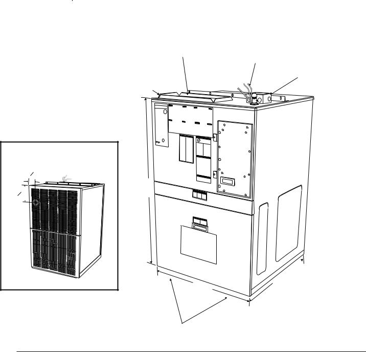
Dimensions (all measurements in inches)
SUPPLY AIR DUCT CONNECTION
8" x 16" LOW VOLTAGE THERMOSTAT CONNECTIONS
|
HIGH VOLTAGE |
¾" DUCT CONNECTION FLANGE |
JUNCTION BOX |
4" x 4" x 2" |
 GAS LINE
CONNECTION
Measurements from Side and Top to Center of Vent Outlet
41 2"
634"
" /8 1
43
27 |
7 |
|
/8" |
RETURN AIR OPENING ON BOTTOM 6" x 22"
" 
7/16 29
HW/HWC-SRM
8/99
Service Reference Manual |
SPECIFICATIONS |
1-7
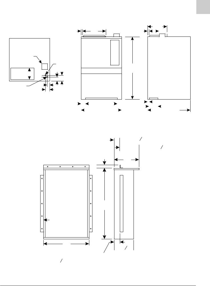
Dimensions (cont.)
|
1 |
|
1 |
133/8 |
|
16 |
8 |
||
|
|
Supply |
|
|
Line Voltage |
|
|
|
|
Box |
Low |
|
|
|
|
|
|
|
|
|
Voltage |
|
43 1/8 |
|
|
|
|
|
|
Supply |
8 |
|
|
|
|
2 7/8 4 |
|
|
|
½ Gas Inlet |
1 3/4 |
|
|
|
|
3 |
Return |
|
|
|
|
|
|
|
2 |
/ |
|
|
|
|
|
|
|
22 |
|
|
|
|
|
1 |
|
|
|
|
|
|
|
|
|
|
|
|
|
|
78 |
|
|
|
|
|
|
|
|
|
|
|
|
|
|
|
6 |
|
|
|
|
|||||||
|
|
|
|
|
|
|
|
|
|
|
|
|
||||||||||||||||
|
|
|
|
|
|
|
|
|
|
|
|
|
|
|
|
|
|
|
|
|
|
|
||||||
|
|
|
|
|
|
|
|
27 7/8 |
|
|
|
|
|
|
|
|
|
|
|
|
29 7/16 |
|||||||
|
|
|
|
|
|
|
|
|
|
|
|
|
|
|
|
|
|
|
|
|
||||||||
|
|
|
|
|
|
|
|
|
|
|
|
|
|
|
|
|
|
|
|
|
|
|
|
|
|
|||
Wall Sleeve (all measurements in inches)
 1 or 3 3 4
 15 or 1214
2
16
45
2 
29
 12 1 2"
Flanges may be assembled
1" or 33 4" from this side of the sleeve
SRM-HW/HWC 8/99
SRM-HW/HWC 2/99
Service Reference Manual |
SEQUENCE OF OPERATIONS |
2-1
Section 2 - Sequence of Operation
HWC123,183,243,303 ........................ |
2-4 |
Simplified Sequence ........................................ |
2-5 |
Detailed Sequence .......................................... |
2-6 |
POWER ...................................................................... |
2-6 |
CALL FOR HEAT ........................................................ |
2-6 |
LIMIT/ROLLOUT OPENS ........................................... |
2-7 |
PRESSURE SWITCH OPENS (BLOCKED FLUE) ..... |
2-7 |
FAILED FLAME SENSE/TRIAL FOR IGNITION ......... |
2-8 |
CALL FOR COOLING ................................................. |
2-8 |
FAN ON....................................................................... |
2-9 |
HW (Heating Only)
(w/UTEC 1097 Spark Ignition System) 2-10
Simplified Sequence ...................................... |
2-11 |
Detailed Sequence ........................................ |
2-12 |
POWER .................................................................... |
2-12 |
CALL FOR HEAT ...................................................... |
2-12 |
LIMIT/ROLLOUT OPENS ......................................... |
2-13 |
PRESSURE SWITCH OPENS (BLOCKED FLUE) ... |
2-13 |
FAILED FLAME SENSE/TRIAL FOR IGNITION ....... |
2-14 |
FAN ON..................................................................... |
2-14 |
HWC122,182,242,302
(w/Fenwal 2461D Ignition Control) ..... 2-16
Simplified Sequence ...................................... |
2-17 |
Detailed Sequence ........................................ |
2-18 |
POWER .................................................................... |
2-18 |
CALL FOR HEAT ...................................................... |
2-18 |
LIMIT OPENS ........................................................... |
2-19 |
PRESSURE SWITCH OPENS (BLOCKED FLUE) ... |
2-19 |
ROLLOUT SWITCH ACTIVATED.............................. |
2-19 |
CALL FOR COOLING ............................................... |
2-19 |
FAN ON..................................................................... |
2-20 |
HW (Heating Only)
(w/Fenwal 2461D Ignition Control) ..... 2-22
Simplified Sequence ...................................... |
2-23 |
Detailed Sequence ........................................ |
2-24 |
POWER .................................................................... |
2-24 |
CALL FOR HEAT ...................................................... |
2-24 |
LIMIT OPENS ........................................................... |
2-25 |
PRESSURE SWITCH OPENS (BLOCKED FLUE) ... |
2-25 |
ROLLOUT SWITCH ACTIVATED.............................. |
2-25 |

SPECIFICATIONS |
Magic-Pak: HW/HWC |
2-2
HWC122,182,242,302 |
|
(w/Fenwal 05-29 Ignition Control) ....... |
2-26 |
Simplified Sequence ...................................... |
2-27 |
Detailed Sequence ........................................ |
2-28 |
POWER .................................................................... |
2-28 |
CALL FOR HEAT ...................................................... |
2-28 |
FLAME SENSE ......................................................... |
2-29 |
LIMIT OPENS ........................................................... |
2-29 |
ROLLOUT SWITCH ACTIVATED.............................. |
2-29 |
CALL FOR COOLING ............................................... |
2-29 |
FAN ON..................................................................... |
2-30 |
HW (Heating Only) |
|
(w/Fenwal 05-29 Ignition Control) ....... |
2-32 |
Simplified Sequence ...................................... |
2-33 |
Detailed Sequence ........................................ |
2-34 |
POWER .................................................................... |
2-34 |
CALL FOR HEAT ...................................................... |
2-34 |
FLAME SENSE ......................................................... |
2-35 |
LIMIT OPENS ........................................................... |
2-35 |
ROLLOUT SWITCH ACTIVATED.............................. |
2-35 |
HWC123,183,243,303 |
|
w/Low Ambient Control ...................... |
2-36 |
HWC122,182,242,302 |
|
w/Low Ambient Control ...................... |
2-38 |
HW/HWC-SRM
2/99

Service Reference Manual |
SEQUENCE OF OPERATIONS |
2-3
BLANK PAGE
SRM-HW/HWC 2/99

SPECIFICATIONS |
Magic-Pak: HW/HWC |
2-4
HWC123, 183, 243, 303
(w/United Technologies 1097 Spark Ignition System)
|
|
|
|
|
|
|
|
CONNECTION DIAGRAM |
|
|
|
CIRCUITS ENERGIZED |
||||||||
208/230-1-60 |
COPPER CONDUCTORS |
|
|
|
|
|
|
|
|
|
|
|
|
|
||||||
|
|
|
|
|
|
|
|
|
|
|
|
OPERATING MODE |
CIRCUIT |
|||||||
POWER SUPPLY |
|
ONLY |
|
|
|
|
|
|
|
|
|
|
|
|
|
|||||
|
|
|
|
|
|
|
|
|
|
|
|
|
|
|
HEATING |
|
R-W |
|||
} |
|
|
|
|
|
|
|
|
|
|
YELLOW |
|
|
|
|
|||||
|
|
|
|
|
|
|
|
|
|
|
|
|
|
|
COOLING |
R-G-Y |
||||
|
|
|
|
|
|
|
|
|
|
|
|
RED |
|
|
|
|
||||
|
|
|
|
|
|
|
|
|
|
|
|
|
|
|
|
FAN |
|
R-G |
||
|
|
|
|
|
|
|
|
|
|
|
|
BLUE |
|
|
|
|
|
|
|
|
|
|
|
|
|
|
|
|
|
|
|
|
BLACK |
|
|
|
LINE VOLTAGE-FACTORY |
|
|||
|
|
|
|
|
|
|
|
|
|
|
|
|
|
|
|
|
|
LINE VOLTAGE-FACTORY WHEN USED |
||
|
|
BLACK |
|
GREEN RED |
WHITE |
2 |
CY |
BLACK L1 |
|
COOL |
UNUSED HEAT |
|
|
|
|
|
|
LINE VOLTAGE-FIELD |
|
|
|
|
|
COMBUSTION |
|
|
CMB |
|
|
|
|
|
|
|
ELECTRODE |
|
|
|
LOW VOLTAGE-FACTORY |
|
|
|
|
|
|
|
|
|
|
|
|
|
|
|
|
|
|
|
LOW VOLTAGE-FIELD |
|
||
|
|
|
BLOWER |
|
|
1 |
|
|
|
|
|
|
|
|
|
|
R |
|
||
|
|
|
|
|
|
|
|
|
|
|
|
|
|
|
|
|
R |
|
||
|
|
|
|
|
|
|
|
|
|
|
|
|
|
|
|
|
|
|
||
|
|
|
|
|
|
|
|
|
|
|
|
|
|
|
|
|
G |
|
G |
|
BLACK |
BLACK |
BLACK BLACK |
PRESSURE SWITCH |
|
|
3 |
RGW |
|
|
|
|
|
24VAC |
|
|
|
|
|
THERMOSTAT |
|
|
|
|
|
|
|
|
|
|
|
|
Y |
|
Y |
|
||||||
|
|
|
|
|
|
4 |
|
|
|
IGNITION |
|
|
WHT |
|
|
W |
|
W } |
|
|
|
|
|
|
|
|
5 |
|
|
CONTROL |
|
FLAME ROD |
|
|
|
|
|
|
|||
|
|
|
VIOLET |
|
|
|
|
|
|
|
|
|
|
|
|
|
|
|||
|
|
|
|
|
|
|
|
|
|
|
|
|
|
|
|
|
|
|
||
|
|
|
|
RED |
|
|
4 |
5 6 |
GND |
|
|
|
|
|
NOTE: |
|
|
|||
|
|
|
|
|
|
1 |
2 |
3 |
|
|
|
|
|
|
|
|
|
|||
|
|
|
|
GAS |
|
|
|
|
|
|
|
|
|
|
IF ANY OF THE ORIGINAL |
|||||
|
|
|
|
|
|
|
|
|
|
|
|
|
|
|
|
|
||||
|
|
|
|
|
|
|
|
|
|
|
|
|
|
|
|
|
WIRES ARE REPLACED, THE |
|||
|
|
|
|
VALVE BLUE |
|
|
|
|
|
|
|
|
|
|
|
|
||||
|
|
|
VIOLET |
|
|
|
|
|
|
|
|
GREEN |
|
|
|
SAME SIZE AND TYPE WIRE |
||||
|
|
|
|
|
|
|
|
|
ORN |
|
|
|
BLUE |
YELLOW |
RED |
MUST BE USED. |
|
|||
|
|
|
|
ORN |
|
|
|
|
|
|
|
|
|
|
||||||
|
|
|
|
|
|
|
|
|
|
|
|
|
|
|
|
|
|
|||
|
|
|
|
|
|
|
|
|
|
|
|
|
|
|
|
|
|
|
|
|
|
|
|
AUTO RESET |
MANUAL RESET |
|
|
|
|
|
|
|
|
|
|
|
|||||
|
|
|
LIMIT SWITCH |
LIMIT SWITCH |
|
|
|
|
|
|
|
|
|
|
|
|
||||
|
|
|
|
ORN |
|
|
|
|
|
|
RED |
|
|
|
|
|
|
|
|
|
|
|
|
|
|
|
|
|
|
|
|
|
|
|
|
|
|
|
|
||
|
|
|
|
|
|
|
|
|
|
|
BLACK |
|
|
|
|
|
|
|
|
|
|
|
CONDENSER FAN |
|
|
|
|
|
|
|
|
|
|
|
|
|
|
|
|
|
|
|
|
VIOLET |
|
|
|
|
|
|
|
|
|
|
|
|
BLUE |
|
|
CONNECTOR BLOCK |
|
|
|
|
|
|
|
|
|
|
|
|
|
TRANSFORMER |
RED |
|
|
|
|
|
|||
CAPACITOR-RUN |
|
|
BLACK |
|
|
|
|
|
|
|
|
|
|
|
|
|||||
|
|
|
|
|
|
|
|
|
|
|
|
|
|
|
EVAP. MOTOR SPEED CONNECTIONS |
|||||
|
|
BROWN |
|
|
|
|
|
|
|
|
|
|
|
|
|
|
|
|||
|
|
|
|
|
|
|
|
|
|
|
|
|
|
|
|
|
MODELS |
HEATING |
COOLING |
|
|
|
|
|
|
|
|
|
|
|
|
|
|
|
BLK |
|
|
|
|||
FAN |
|
|
BLACK |
|
|
|
|
|
|
|
|
|
|
|
26HWC123 |
LOW (RED) |
MED (BLUE) |
|||
|
|
|
|
|
|
|
208 V |
|
|
|
|
|
|
|||||||
COM |
HERM |
YELLOW |
|
C |
|
|
|
|
|
|
|
240 V |
|
|
|
38HWC123 |
HIGH(BLACK) MED (BLUE) |
|||
S |
COMP |
|
|
|
|
|
|
|
|
|
|
|
|
|
||||||
|
|
|
|
|
|
|
|
|
BLK |
|
|
|
|
|
|
38HWC183 |
LOW (RED) |
LOW (RED)* |
||
|
|
|
|
RED |
|
|
|
|
|
|
|
|
|
|
|
|||||
|
|
|
|
R |
|
|
|
|
|
CONTACTOR |
|
|
|
|
51HWC183 |
MED (BLUE) |
LOW (RED) |
|||
|
|
RED |
|
|
|
|
|
|
|
|
|
|
|
64HWC183 |
HIGH(BLACK) LOW (RED) |
|||||
RED |
|
|
|
|
|
|
|
|
|
|
|
|
|
|
|
|
||||
|
|
SEE CHART |
|
|
|
|
|
T1 |
|
|
|
L1 |
|
|
|
38HWC243 |
LOW (RED) |
MED (BLUE) |
||
D |
|
|
FOR WIRING |
BLOWER |
|
|
|
|
|
|
|
|
|
|
|
|
|
51HWC243 |
MED (BLUE) |
MED (BLUE)* |
|
|
|
|
CONTROL |
|
|
|
T2 |
|
|
|
L2 |
|
|
|
64HWC243 |
HIGH(BLACK) MED (BLUE) |
|||
|
|
|
BLACK |
|
|
|
|
|
|
|
|
|
|
51HWC303 |
MED (BLUE) |
HIGH(BLACK) |
||||
|
YELLOW |
|
H |
|
|
|
|
|
|
|
|
|
|
|
|
|
||||
|
|
BLUE |
|
|
|
|
|
|
|
|
|
|
|
|
|
64HWC303 |
HIGH(BLACK) HIGH(BLACK)* |
|||
|
|
BLOWER |
M |
|
|
|
|
|
|
|
|
|
|
|
|
|
||||
|
BROWN |
RED |
|
|
|
|
|
|
|
|
|
|
|
|
|
*JUMPER REQUIRED |
|
|||
|
MOTOR |
L |
|
|
|
|
|
|
|
|
|
|
|
|
|
|
||||
CAPACITOR |
|
|
|
|
|
|
|
|
|
|
|
|
BLUE |
|
|
|
|
|
|
|
|
|
|
|
|
|
|
|
|
|
|
|
|
|
|
|
|
|
|
||
BLOWER |
|
|
|
|
|
|
|
|
|
|
|
|
|
YELLOW |
|
|
|
|
|
|
|
|
|
|
|
|
|
|
|
|
|
|
|
|
|
|
|
|
|
|
|
|
|
#45004-1 |
|
|
|
|
|
|
|
|
|
|
|
|
|
|
|
|
|
|
|
|
|
DIAGNOSTICS |
||
|
|
|
|||
|
|
|
The following blower/ignition control board |
||
|
|
|
LED codes will indicate normal or abnormal |
||
|
|
|
operations: |
|
|
|
|
|
SLOW FLASH |
Normal Operation, No |
|
|
|
|
|
Call for Heat |
|
Note: On units that are equipped with a low ambient switch (designated |
FAST FLASH |
Normal Operation, Call for |
|||
with an “SA” in the model number), sequence of operation during |
|
Heat |
|||
2 FLASH |
System Lockout - Failed to |
||||
cooling call is modified when outdoor temperatures fall below the |
|||||
|
Detect or Sustain Flame |
||||
normal operating range. For more information on the low ambient |
3 FLASH |
Pressure Switch Open or |
|||
switch equipped version of this unit, see the section beginning on |
|||||
|
Closed |
||||
page 2-36. |
4 FLASH |
High Limit or Rollout |
|||
|
|
|
|
Switch Open |
|
|
|
|
5 FLASH |
Flame Sensed and Gas |
|
|
|
|
|
Valve Not Energized |
|
|
|
|
STEADY |
Internal Failure |
|
|
|
|
|
(Micro-controller Failure; |
|
|
|
|
|
Self-check) |
|
FIGURE 2-1 Connection Diagram |
|
|
|||
|
|
||||
HW/HWC-SRM
2/99

Service Reference Manual |
SEQUENCE OF OPERATIONS |
2-5
Simplified Sequence - HWC123,183, 243, 303
Refer to Figure 2-1
•208/230V power is supplied to the junction box on top of the unit
•24V power is supplied from the unit transformer to the thermostat
CALL FOR HEAT
1.The thermostat closes the R-W circuit, sending a 24-volt signal to the unit.
2.The 24-volt signal energizes the combustion blower, causing the pressure switch to close.
3.The combustion blower runs for 30 seconds as a pre-purge to trial for ignition.
4.The ignition control energizes the spark ignition and opens the gas valve, causing the burners to light. When the gas valve energizes, a 30-second circulating air blower “on” delay begins.
5.Flame sense is sent to the ignition control through the flame sensor and flame sense wire.
6.After the 30-second delay, the circulating air blower energizes and runs until the heat call is satisfied.
7.When the heat call is satisfied, the gas valve deenergizes. This shuts down the burners.
8.A 5-second combustion blower post-purge delay and a 120-second circulating air blower “off” delay start.
9.After the delay times elapse, the combustion blower and the circulating air blower stop.
FLAME SENSE
1.After the burners have been lit, the ignition control starts a 10-second trial for ignition delay.
2.If after 10 seconds a flame has not been sensed by the ignition control, the ignition control de-energizes the gas valve and the spark ignitor.
3.The unit initiates three trials for ignition (flame sense) before system lockout.
4.System lockout lasts 60 minutes or until power is reset to unit (whichever comes first).
CALL FOR COOLING
1.The thermostat energizes the R, Y and G circuit, sending a 24-volt signal to the cooling contactor and the ignition control to start the cooling sequence.
2.The contactor closes immediately, causing the compressor and the condenser fan to run.
3.The 24-volt Y signal starts a 5-second circulating air blower “on” delay.
4.After 5 seconds, the circulating air blower starts and runs until the R, Y and G circuit is interrupted by the thermostat.
5.When the R, Y and G circuit is interrupted, the cooling contactor immediately de-energizes. This causes the compressor and the condenser fan to stop.
6.The ignition control starts a 90-second circulating air blower “off” delay.
7.After 90 seconds, the circulating air blower stops.
FAN ON
1.The thermostat energizes the R-G circuit, causing the circulating air blower to energize in cooling speed.
2.The circulating air blower remains running in cooling speed until the thermostat is switched to the “AUTO” position.
SRM-HW/HWC 2/99
Detailed Sequence follows 

SPECIFICATIONS |
Magic-Pak: HW/HWC |
2-6
Detailed Sequence - HWC123, 183, 243, 303
Refer to Figure 2-1
POWER
Line Voltage
With the unit at rest (no call from the thermostat), line voltage will be present:
L1 Power
1.Through the L1 black lead to the L1 terminal on the ignition control
2.At the L1 contactor terminal
3.At the transformer terminal marked 208-240V
L2 Power
1.Through the L2 black lead to the induced draft blower
2.At the L2 contactor terminal
3.A transformer common terminal
4.At the T2 contactor terminal
5.At the R terminal of the compressor
6.At the capacitor common terminals
Low Voltage (24 VAC)
With the unit at rest (no call from the thermostat), 24 volts A/C will be present:
1.From the transformer 24V terminal to pin 4 of the 6-pin chassis low voltage harness
2.From pin 4 of the chassis low voltage harness to the
24VAC hot terminal on the ignition control
3.From the 24VAC hot terminal to pin 5 of the 5-pin thermostat harness (internal to board)
4.From the 24VAC hot terminal also to pin 6 of the 6- pin ignition wire harness
5.From pin 6 of the ignition wire harness through the auto reset limit switch and the manual reset rollout switch to pin 1 of the 6-pin ignition wire harness
Note: While the unit is at rest, the green LED shows consistent slow flash. This indicates normal operation - system at rest (standby mode).
CALL FOR HEAT
Line Voltage
The ignition control receives a signal from the R-W circuit indicating a call for heat.
1.The combustion blower relay energizes, sending L1 power to CMB BLWR terminal on the ignition
control. This causes the combustion blower to start by completing the line voltage circuit through the L2 wire connection in the unit.
2.As the 24-volt signal is sent to pin 4 of the 6-pin ignition wire harness by the ignition control, a 30second circulating air blower “on” delay starts. After the delay, the ignition control energizes the heat speed blower relay. This sends L1 power to the
ACB HEAT terminal on the ignition control.
3.L1 power is then sent to the circulating air blower terminal block where it is connected to the blower motor. The circulating air blower starts by completing the L1-L2 circuit through the L2 connection at the blower motor capacitor.
4.The combustion blower and the circulating air blower continue to run until the R-W circuit is interrupted. After a 5-second post-purge delay, the
CMB BLWR terminal on the ignition control deenergizes. This interrupts L1 power to the combustion blower. After a 120-second circulating air blower “off” delay, the ACB HEAT terminal deenergizes. This interrupts L1 to the circulating air blower. As L1 power is interrupted, the blowers shut off.
Low Voltage
1.A call for heat closes the R-W circuit, sending a 24volt signal to the low voltage white wire in the unit.
2.The 24-volt signal is received at pin 3 of the 5-pin thermostat harness on the ignition control.
3.The 24-volt signal causes the combustion blower relay to close, causing the combustion blower to run. At this time, a 24-volt signal is also sent out through pin 2 of the 6-pin ignition wire harness.
4.The 24-volt signal from pin 2 of the 6-pin ignition wire harness energizes one side of the Normally Open pressure switch. As the induced draft blower reaches full speed, the pressure switch closes and a 24-volt signal is sent to pin 5 of the 6- pin ignition wire harness.
5.When the 24-volt signal is received at pin 5 of the 6- pin ignition wire harness, the ignition control starts a 30-second pre-purge delay.
6.After the 30-second pre-purge, the ignition control initiates a trial for ignition. The spark ignition cable terminal and pin 4 of the 6-pin ignition wire harness energize simultaneously.
7.When the 24-volt signal is present at pin 4 of the 6- pin ignition wire harness, the ignition control starts a 30-second circulating air blower “on” delay.
8.The 24-volt signal from pin 4 of the 6-pin ignition wire harness is received at the gas valve, causing it to open and the burners to ignite.
HW/HWC-SRM
2/99

SRM-HW/HWC 2/99
Service Reference Manual
9.After 30-second “on” delay, the circulating air blower relay energizes the heat terminal and the circulating air blower is energized.
10.The unit will continue to operate normally until the R-W circuit is interrupted.
11.When the heat call is satisfied, the thermostat will interrupt the R-W circuit. This causes the 24-volt signal to the white wire in the unit to be de-ener- gized.
12.The gas valve closes immediately as 24V through pin 4 of the 6-pin ignition wire harness is deenergized by the ignition control.
13.The ignition control initiates a 120-second circulating air blower “off” delay and 5-second combustion blower post-purge delay.
14.After 5 seconds, the combustion blower shuts off.
15.After 120 seconds, the circulating air blower shuts off and the system returns to standby mode.
Note: During a call for heat, the green LED shows consistent fast flash (as long as the R-W circuit is closed). When the R-W circuit is interrupted (indicating the heat call has been satisfied), the green LED returns to a consistent slow flash.
LIMIT/ROLLOUT OPENS
In all modes of operation, 24VAC is supplied to the ignition control 24VAC hot terminal and is passed through the ignition control to pin 6 of the 6-pin ignition wire harness.
1.A 24-volt signal is sent from pin 6 of the 6-pin ignition wire harness to one side of the Normally Closed manual reset rollout switch, across the rollout switch to one side of the Normally Closed auto reset limit switch and across the limit switch to pin 1 of the 6-pin ignition wire harness.
2.This circuit energizes whenever line voltage power is supplied to the unit.
3.If the circuit is interrupted by either switch opening, the 24-volt signal to pin 1 of the 6-pin ignition wire harness de-energizes.
4.This causes the combustion blower relay to energize, sending L1 power to the CMB BLWR terminal on the ignition control. It also causes the circulating air blower heat speed relay to energize, sending L1 power to the ACB HEAT terminal on the ignition control. This causes both blowers to start immediately.
5.The ignition control lockouts the spark ignition cable terminal and pin 4 of the 6-pin ignition wire harness until the 24-volt signal is restored at pin 1 of the 6-pin ignition wire harness.
6.The circulating air blower and the combustion blower are energized until the 24-volt signal is restored at pin 1 of the 6-pin ignition wire harness.
SEQUENCE OF OPERATIONS
2-7
7.The green ignition control LED shows a 4 flash fault code (indicating limit switch/rollout switch open).
8.When the 24-volt signal is restored at pin 1 of the 6- pin ignition wire harness, the ignition control starts a 5-second combustion blower post-purge delay and a 120-second circulating air blower “off” delay.
9.Once the delays have timed out, both blowers stop and the green LED flashes a consistent slow flash if no heat call is present. (A consistent fast flash appears if there is a call for heat.)
Note: The limit switch resets automatically when temperatures are acceptable, but the rollout switch must be manually reset by pushing in on the small button on top of the switch.
The reason why the switches opened must be determined before any corrective action is taken.
PRESSURE SWITCH OPENS (BLOCKED FLUE)
When the R-W circuit is energized, a 24-volt signal is sent to the ignition control. This starts the call for heat.
1.The 24-volt signal from the R-W circuit energizes the combustion blower relay, sending L1 power to the CMB BLWR terminal on the ignition control. This starts the ignition control.
2.At the same time the combustion blower relay energizes, the 24-volt signal is sent to pin 2 of the 6- pin ignition wire harness and from pin 2 to one side of the Normally Open pressure switch.
3.When the combustion blower causes the pressure switch to close, a 24-volt signal is sent across the switch to pin 5 of the 6-pin ignition wire harness. The 24-volt signal energizes at pin 5 and the ignition sequence continues.
4.If the combustion blower fails to close the pressure switch, the 24-volt signal is not sent to pin 5 of the 6-pin ignition wire harness and the ignition control does not initiate a 30-second pre-purge delay.
5.No signal is sent to the spark ignition cable terminal on the ignition control or to the gas valve through pin 4 of the 6-pin ignition wire harness.
6.The combustion blower continues to run for 60 seconds. After 60 seconds, the ignition control automatically de-energizes the combustion blower relay. This interrupts L1 power to the CMB BLWR terminal on the ignition control.
7.The combustion blower remains de-energized for approximately six minutes. During this 6-minute lockout, the green LED flashes three times (indicating pressure switch fault—open or closed).

SPECIFICATIONS
2-8
8.The 24-volt signal will only be supplied to the limit switch circuit through pin 6 of the 6-pin ignition wire harness and to the pressure switch circuit through pin 2 of the 6-pin ignition wire harness.
9.The system will repeat this sequence until the pressure switch closes and the 24-volt signal is restored at pin 5 of the 6-pin ignition wire harness.
FAILED FLAME SENSE/TRIAL FOR IGNITION
When the pressure switch closes and a 24-volt signal is sent to pin 5 of the 6-pin ignition wire harness, the spark ignition cable terminal and pin 4 of the 6-pin ignition wire harness energize.
1.As spark voltage is supplied to the ignitor electrodes, the gas valve opens and this causes the burners to ignite.
2.The ignition control continues to energize spark voltage until a flame sense signal is supplied to the flame terminal on the ignition control.
3.If a flame sense signal is not received at the flame terminal on the ignition control, the spark ignition cable terminal remains energized for 10 seconds.
4.After the 10-second trial for ignition, the ignition control de-energizes the spark ignition cable terminal and pin 4 of the 6-pin ignition wire harness. This causes the gas valve to close and the electrode spark to stop.
5.Once the 24-volt signal is sent to pin 4 of the 6-pin ignition wire harness, a 30-second circulating air blower “on” delay starts. After the delay is timed out, the circulating air blower starts.
6.After the spark ignition cable terminal de-ener- gizes, the ignition control initiates a 30-second combustion blower inter-purge delay.
7.After 30-second inter-purge, the ignition control energizes the spark ignition cable terminal and pin 4 of the 6-pin ignition wire harness. If the flame sense signal is received at the flame terminal of the ignition control, the unit continues heat call.
8.If the flame sense signal is not received, the system goes through three trials following the above sequence.
9.After three trials, the system goes into lockout and only the high limit switch circuit and pressure switch circuit remain energized during the 60minute lockout period.
10.If the flame sense is lost during the heat cycle, the gas valve de-energizes immediately and the system goes into the trial sequence.
Magic-Pak: HW/HWC
CALL FOR COOLING
Line Voltage
1.L2 power passes through the fixed closed L2-T2 terminals on the contactor to the RUN terminal of the compressor and the COMMON terminal of the capacitor.
2.L1 power is sent to the L1 terminal of the contactor. When the Y signal energizes the contactor, the T2 terminal becomes energized. L1 power is sent to the compressor COMMON terminal and the condenser fan. This energizes the compressor and condenser fan motors.
3.When pin 1 (Y terminal) of the 5-pin thermostat harness receives a 24-volt signal from the thermostat, a 5-second circulating air blower delay starts.
4.After the 5-second delay, the ignition control energizes the cooling speed relay. This sends L1 power to the ACB COOL terminal of the ignition control.
5.L1 power is sent to the circulating air blower terminal block, energizing the circulating air blower motor.
6.When the R, Y and G circuit is interrupted by the thermostat, the contactor is immediately deenergized. This interrupts L1 power to the compressor and condenser fan motors, stopping both.
7.The ignition control starts a 90-second circulating air blower “off” delay, after which the ACB COOL terminal de-energizes. This interrupts L1 power to the circulating air blower motor, causing it to stop.
Low Voltage
1.The thermostat energizes the R, Y and G circuit, sending a 24-volt signal to the contactor coil and to pin 1 of the 5-pin thermostat harness connected to the ignition control.
2.The contactor closes immediately upon receiving the 24-volt signal, causing the compressor and condenser fan motors to start.
3.The 24-volt signal is also sent to pin 1 of the 5-pin thermostat harness, initiating a 5-second circulating air blower “on” delay.
4.After the 5-second delay, the ignition control energizes the cooling speed relay and the circulating air blower starts.
5.When the cooling call is satisfied, the thermostat interrupts the R, Y and G circuit. The contactor de-energizes immediately, causing the compressor and the condenser fan to stop. The ignition control starts a 90-second circulating air blower
“off” delay.
HW/HWC-SRM
2/99

Service Reference Manual |
SEQUENCE OF OPERATIONS |
2-9
6.After the 90-second delay, the ignition control deenergizes the cooling speed relay and the circulating air blower stops.
FAN ON
1.When the thermostat is switched to the “FAN ON” position, the R-G circuit sends a 24-volt signal to pin 4 of the 5-pin thermostat harness.
2.The 24-volt signal energizes the cooling speed relay, sending L1 power to the ACB COOL terminal of the ignition control.
3.L1 power is sent to the circulating air blower terminal block, causing the circulating air blower to run in cooling speed.
4.The circulating air blower continues to run in cooling speed until the thermostat is switched to “AUTO”, interrupting the R-G circuit.
Note: With the thermostat in the “FAN ON” position during heat call, ignition control will not energize the heat speed relay. The circulating air blower continues to run in cooling speed unless the limit switch circuit opens, which would cause the heat speed relay and the induced draft blower relay to become energized. This would de-energize the cooling speed relay until either the limit switch circuit is closed or the thermostat is switched to the “AUTO” position.
SRM-HW/HWC 2/99
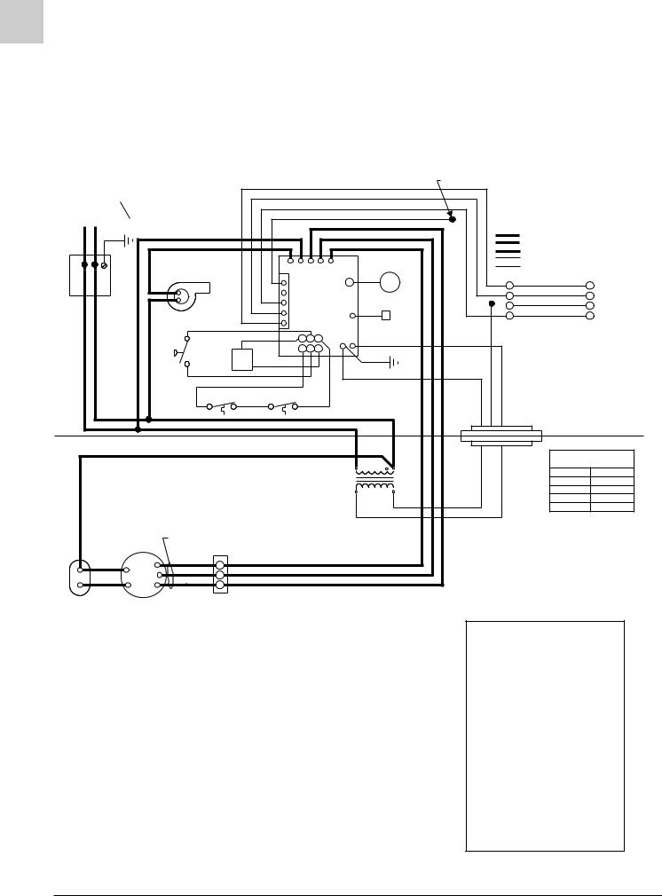
SPECIFICATIONS |
Magic-Pak: HW/HWC |
2-10
HW (Heating Only)
(w/United Technologies 1097 Spark Ignition System)
CONNECTION DIAGRAM
WIRE NUT |
CIRCUITS ENERGIZED |
|
|
|
|
|
|
|
|
|
|
|
|
|
|
|
|
OPERATING MODE |
CIRCUIT |
|||
208/230-1-60 |
COPPER CONDUCTORS |
|
|
|
|
|
|
|
|
|
|
|
|
|
|
|
HEATING |
R-W |
||
POWER SUPPLY |
|
ONLY |
|
|
|
|
|
|
|
|
YELLOW |
|
|
|
|
COOLING |
R-G-Y |
|||
} |
|
|
|
|
|
|
|
|
|
|
RED |
|
|
|
|
|
|
FAN |
R-G |
|
|
|
|
|
|
|
|
|
|
|
|
|
|
|
|
|
|
||||
|
|
|
|
|
|
|
|
|
|
|
|
|
|
|
|
|
|
|
|
|
|
|
|
|
|
|
|
|
|
|
|
BLUE |
|
|
|
|
|
LINE VOLTAGE-FACTORY |
|||
|
|
|
|
|
|
|
|
|
|
|
BLACK |
|
|
|
|
|
LINE VOLTAGE-FACTORY WHEN USED |
|||
|
|
|
|
|
|
|
|
|
|
|
|
|
|
|
|
LINE VOLTAGE-FIELD |
|
|||
|
|
|
|
|
|
|
|
|
|
|
|
|
|
|
|
|
|
|
||
|
BLACK |
|
RED |
GREEN |
WHITE |
|
Y |
L1 |
COOL |
HEAT |
UNUSED |
|
|
|
|
|
|
LOW VOLTAGE-FACTORY |
||
|
|
COMBUSTION |
|
|
|
|
CNB |
|
|
|
|
|
ELECTRODE |
|
|
|
LOW VOLTAGE-FIELD |
|
||
|
|
|
|
|
|
|
|
|
|
|
|
|
|
|
|
|||||
|
|
|
|
|
|
|
|
|
|
|
|
|
|
|
|
|
|
|
|
|
|
|
BLOWER |
|
|
|
1 |
|
|
|
|
|
|
|
|
|
|
|
R |
|
|
|
|
|
|
|
|
|
|
|
|
|
|
|
|
|
|
|
R |
|
||
|
|
|
|
|
|
|
|
|
|
|
|
|
|
|
|
|
|
|
||
|
|
|
|
|
|
2 |
C |
|
|
|
|
|
|
|
|
|
|
G |
G |
THERMOSTAT |
|
BLACK BLACK |
|
|
|
|
|
R G W |
|
|
|
|
|
|
|
|
|
|
|||
BLACK BLACK |
PRESSURE SWITCH |
|
|
|
3 |
|
|
|
|
24VAC |
|
|
|
|
|
|
|
|||
VALVE BLUE |
|
|
|
|
|
|
|
|
|
WIRES ARE REPLACED, THE |
||||||||||
|
|
|
|
|
|
|
|
|
|
|
|
|
|
|
|
|
|
Y |
Y |
|
|
|
|
|
|
|
4 |
|
|
IGNITION |
|
WHT |
|
|
|
W |
W } |
|
|||
|
|
|
|
|
|
5 |
|
|
CONTROL |
|
FLAME ROD |
|
|
|
|
|
|
|||
|
|
VOILET |
|
|
|
|
|
|
|
|
|
|
|
|
|
|
|
|
|
|
|
|
|
|
RED |
|
|
4 |
5 6 |
|
GND |
|
|
|
|
|
|
|
|
|
|
|
|
|
|
|
|
1 |
2 3 |
|
|
|
|
|
|
|
|
NOTE: |
|
|
||
|
|
|
GAS |
|
|
|
|
|
|
ORANGE |
|
|
|
|
BLUE |
YELLOW |
RED |
IF ANY OF THE ORIGINAL |
||
|
|
VOILET |
|
|
|
|
|
|
|
|
GREEN |
|
SAME SIZE AND TYPE WIRE |
|||||||
|
|
|
|
|
|
|
|
|
|
|
|
|
|
|
||||||
|
|
|
|
|
|
|
|
|
|
|
|
|
|
|
|
|
||||
|
|
|
ORANGE |
|
|
|
|
|
|
|
|
|
|
|
|
|
|
MUST BE USED. |
|
|
|
|
AUTO RESET |
|
MANUAL RESET |
|
|
|
|
|
|
|
|
|
|
|
|||||
|
|
LIMIT SWITCH |
|
|
LIMIT SWITCH |
|
|
|
|
|
|
|
|
|
|
|
||||
|
|
|
ORANGE |
|
|
|
|
BLACK |
|
|
|
|
|
|
CONNECTOR |
|
|
|||
|
|
|
|
|
|
|
|
|
|
|
|
|
|
|
|
|
|
|||
|
|
|
|
|
|
|
|
|
|
|
|
|
|
|
|
|
|
|
|
|
|
|
|
|
|
|
|
|
|
|
|
RED |
|
|
|
|
|
|
BLOCK |
|
|
|
|
YELLOW |
|
|
|
|
|
|
|
|
|
|
|
|
|
|
EVAP. MOTOR |
|||
|
|
|
|
|
|
|
|
|
|
|
|
|
|
|
|
|
|
|||
|
|
|
|
|
|
|
|
|
|
|
|
|
208 V |
240 V |
|
|
|
SPEED CONNECTIONS |
||
|
|
|
|
|
|
|
|
|
|
|
|
|
|
|
|
MODELS |
HEATING |
|||
|
|
|
|
|
|
|
|
TRANSFORMER |
|
|
|
|
|
|||||||
|
|
|
|
|
|
|
|
|
|
|
|
|
26HW |
LOW (RED) |
||||||
|
|
|
|
|
|
|
|
|
|
|
|
|
|
|
|
|
|
|||
|
|
|
|
|
|
|
|
|
|
|
|
|
|
|
|
|
|
38HW |
HIGH (BLACK) |
|
|
|
|
|
|
|
|
|
|
|
|
|
|
|
|
BLUE |
|
|
51HW |
MED (BLUE) |
|
|
|
|
|
|
|
|
|
|
|
|
|
|
|
|
|
|
64HW |
HIGH (BLACK) |
||
|
|
|
|
|
|
|
|
|
|
|
|
|
|
|
RED |
|
|
|||
|
|
|
|
|
|
|
|
|
|
|
|
|
|
|
|
|
|
|
|
|
|
|
SEE |
|
|
|
|
|
|
|
|
|
|
|
|
|
|
|
|
|
|
|
|
CHART |
|
|
|
|
|
|
|
|
|
|
|
|
|
|
|
|
|
|
|
|
FOR WIRING |
|
|
|
|
|
|
|
|
|
|
|
|
|
|
|
#45008-2 |
|
|
YELLOW |
|
BLACK |
H |
|
|
|
|
|
|
|
|
|
|
|
|
|
|
|
|
|
|
BLOWER |
BLUE |
M |
|
|
|
|
|
|
|
|
|
|
|
|
|
|
|
|
|
|
|
|
|
|
|
|
|
|
|
|
|
|
|
|
|
|
|
|
||
BROWN |
MOTOR |
RED |
|
|
|
|
|
|
|
|
|
|
|
|
|
|
|
|
|
|
L |
|
|
|
|
|
|
|
|
|
|
|
|
|
|
|
|
|
|||
|
|
|
|
|
|
|
|
|
|
|
|
|
|
|
|
|
|
|
|
|
CAPACITOR |
|
TERMINAL BLOCK |
|
|
|
|
|
|
|
|
|
|
|
|
|
|
|
|
|
|
BLOWER |
|
|
|
|
|
|
|
|
|
|
|
|
|
|
|
|
|
|
|
|
DIAGNOSTICS
The following blower/ignition control board LED codes will indicate normal or abnormal operations:
SLOW FLASH |
Normal Operation, No |
|
Call for Heat |
FAST FLASH |
Normal Operation, Call for |
|
Heat |
2 FLASH |
System Lockout - Failed to |
|
Detect or Sustain Flame |
3 FLASH |
Pressure Switch Open or |
|
Closed |
4 FLASH |
High Limit or Rollout |
|
Switch Open |
5 FLASH |
Flame Sensed and Gas |
|
Valve Not Energized |
STEADY |
Internal Failure |
|
(Micro-controller Failure; |
|
Self-check) |
FIGURE 2-2 Connection Diagram
HW/HWC-SRM
2/99
Service Reference Manual |
SEQUENCE OF OPERATIONS |
2-11
Simplified Sequence - HW (w/UTEC 1097 Board)
Refer to Figure 2-2
CALL FOR HEAT
1.The indoor thermostat energizes the R-W circuit, sending a 24-volt signal to the ignition control.
2.The 24-volt signal causes the induced draft blower to start, which closes the pressure switch.
3.Once the pressure switch closes, a 30-second induced draft blower pre-purge starts.
4.After the 30-second induced draft blower pre-purge, the gas valve opens and the burners ignite. This starts a 30-second circulating air blower “on” delay.
5.The unit continues to operate in the heat mode until the indoor thermostat setting is reached. At that time, the R-W circuit is interrupted.
6.The 24-volt signal to the ignition control is interrupted, causing the gas valve to close and the burners to shut down.
7.A 5-second post-purge starts and following that the induced draft blower stops.
8.A 120-second circulating air blower “off” delay starts. After the elapsed time, the circulating air blower stops.
FAN ON
1.When the thermostat is switched to the “FAN ON” position, a 24-volt signal is sent to the ignition control.
2.The ignition control immediately energizes the cooling speed of the circulating air blower.
3.The circulating air blower runs in the cooling speed until the thermostat fan switch is moved back to the “AUTO” position. At this time, the circulating air blower stops.
During the call for “FAN ON”, the circulating air blower heat speed will not be energized by the ignition control unless the limit switch circuit is interrupted.
SRM-HW/HWC 2/99
Detailed Sequence follows 

SPECIFICATIONS |
Magic-Pak: HW/HWC |
2-12
Detailed Sequence - HW (w/UTEC 1097 Board)
Refer to Figure 2-2
POWER
Line Voltage
With the unit at rest (no call from the thermostat), line voltage will be present:
L1 Power
1.Through the L1 black lead to the L1 terminal on the ignition control
2.At the transformer terminal marked 208-240V
L2 Power
1.Through the L2 black lead to the induced draft blower
2.Transformer common terminal
3.At the circulating air blower capacitor terminal
Low Voltage (24 VAC)
With the unit at rest (no call from the thermostat), 24 volts A/C will be present:
1.At the transformer 24V terminal
2.At the 24VAC hot terminal on the ignition control
3.At pin 5 of the 5-pin thermostat harness (red wire pin)
4.At pin 6 of the 6-pin ignition wire harness
5.Through the auto reset limit switch and the manual reset rollout switch to pin 1 of the 6-pin ignition wire harness
Note: While the unit is at rest, the green LED shows consistent slow flash. This indicates normal operation - system at rest (standby mode).
CALL FOR HEAT
Line Voltage
The ignition control receives a signal from the R-W circuit indicating a call for heat.
1.The combustion blower relay energizes, sending L1 power to CMB BLWR terminal on the ignition control. This causes the combustion blower to start.
2.As the 24-volt signal is sent to pin 4 of the 6-pin ignition wire harness by the ignition control, a 30second circulating air blower “on” delay starts. After the delay, the ignition control energizes the heat speed blower relay. This sends L1 power to the ACB HEAT terminal on the ignition control.
3.L1 power is then sent to the circulating air blower terminal block where it is connected to the blower motor, starting the circulating air blower.
4.The combustion blower and the circulating air blower continue to run until the R-W circuit is interrupted. After a 5-second post-purge delay, the
CMB BLWR terminal on the ignition control deenergizes. This interrupts L1 power to the combustion blower. After a 120-second circulating air blower “off” delay, the ACB HEAT terminal deenergizes. This interrupts L1 to the circulating air blower. As L1 power is interrupted, the blowers shut off.
Low Voltage
1.A call for heat closes the R-W circuit, sending a 24volt signal to the low voltage white wire in the unit.
2.The 24-volt signal is received at pin 3 of the 5-pin thermostat harness on the ignition control.
3.The 24-volt signal causes the combustion blower relay to close, causing the combustion blower to run. At this time, a 24-volt signal is also sent out through pin 2 of the 6-pin ignition wire harness.
4.The 24-volt signal from pin 2 of the 6-pin ignition wire harness energizes one side of the Normally Open pressure switch. As the induced draft blower reaches full speed, the pressure switch closes and a 24-volt signal is sent to pin 5 of the 6- pin ignition wire harness.
5.When the 24-volt signal is received at pin 5 of the 6- pin ignition wire harness, the ignition control starts a 30-second pre-purge delay.
6.After the 30-second pre-purge, the ignition control initiates a trial for ignition. The spark ignition cable terminal and pin 4 of the 6-pin ignition wire harness energize simultaneously.
7.When the 24-volt signal is present at pin 4 of the 6- pin ignition wire harness, the ignition control starts a 30-second circulating air blower “on” delay.
8.The 24-volt signal from pin 4 of the 6-pin ignition wire harness is received at the gas valve, causing it to open and the burners to ignite.
9.After 30-second “on” delay, the circulating air blower relay energizes the heat terminal and the circulating air blower is energized.
10.The unit will continue to operate normally until the R-W circuit is interrupted.
11.When the heat call is satisfied, the thermostat will interrupt the R-W circuit. This causes the 24-volt signal to the white wire in the unit to be de-ener- gized.
HW/HWC-SRM
2/99

SRM-HW/HWC 2/99
Service Reference Manual
12.The gas valve closes immediately as 24V through pin 4 of the 6-pin ignition wire harness is deenergized by the ignition control.
13.The ignition control initiates a 120-second circulating air blower “off” delay and 5-second combustion blower post-purge delay.
14.After 5 seconds, the combustion blower shuts off.
15.After 120 seconds, the circulating air blower shuts off and the system returns to standby mode.
Note: During a call for heat, the green LED shows consistent fast flash (as long as the R-W circuit is closed). When the R-W circuit is interrupted (indicating the heat call has been satisfied), the green LED returns to a consistent slow flash.
LIMIT/ROLLOUT OPENS
In all modes of operation, 24VAC is supplied to the ignition control 24VAC hot terminal and is passed through the ignition control to pin 6 of the 6-pin ignition wire harness.
1.A 24-volt signal is sent from pin 6 of the 6-pin ignition wire harness to one side of the Normally Closed manual reset rollout switch, across the rollout switch to one side of the Normally Closed auto reset limit switch and across the limit switch to pin 1 of the 6-pin ignition wire harness.
2.This circuit energizes whenever line voltage power is supplied to the unit.
3.If the circuit is interrupted by either switch opening, the 24-volt signal to pin 1 of the 6-pin ignition wire harness de-energizes.
4.This causes the combustion blower relay to energize, sending L1 power to the CMB BLWR terminal on the ignition control. It also causes the circulating air blower heat speed relay to energize, sending L1 power to the ACB HEAT terminal on the ignition control. This causes both blowers to start immediately.
5.The ignition control lockouts the spark ignition cable terminal and pin 4 of the 6-pin ignition wire harness until the 24-volt signal is restored at pin 1 of the 6-pin ignition wire harness.
6.The circulating air blower and the combustion blower are energized until the 24-volt signal is restored at pin 1 of the 6-pin ignition wire harness.
7.The green ignition control LED shows a 4 flash fault code (indicating limit switch/rollout switch open).
8.When the 24-volt signal is restored at pin 1 of the 6- pin ignition wire harness, the ignition control starts a 5-second combustion blower post-purge delay and a 120-second circulating air blower “off” delay.
SEQUENCE OF OPERATIONS
2-13
9.Once the delays have timed out, both blowers stop and the green LED flashes a consistent slow flash if no heat call is present. (A consistent fast flash appears if there is a call for heat.)
Note: The limit switch resets automatically when temperatures are acceptable, but the rollout switch must be manually reset by pushing in on the small button on top of the switch.
The reason why the switches opened must be determined before any corrective action is taken.
PRESSURE SWITCH OPENS (BLOCKED FLUE)
When the R-W circuit is energized, a 24-volt signal is sent to the ignition control. This starts the call for heat.
1.The 24-volt signal from the R-W circuit energizes the combustion blower relay, sending L1 power to the CMB BLWR terminal on the ignition control. This starts the ignition control.
2.At the same time the combustion blower relay energizes, the 24-volt signal is sent to pin 2 of the 6- pin ignition wire harness and from pin 2 to one side of the Normally Open pressure switch.
3.If the combustion blower causes the pressure switch to close, a 24-volt signal is sent across the switch to pin 5 of the 6-pin ignition wire harness. The 24-volt signal energizes at pin 5 and the ignition sequence continues.
4.If the combustion blower fails to close the pressure switch, the 24-volt signal is not sent to pin 5 of the 6-pin ignition wire harness and the ignition control does not initiate a 30-second pre-purge delay.
5.No signal is sent to the spark ignition cable terminal on the ignition control or to the gas valve through pin 4 of the 6-pin ignition wire harness.
6.The combustion blower continues to run for 60 seconds. After 60 seconds, the ignition control automatically de-energizes the combustion blower relay. This interrupts L1 power to the CMB BLWR terminal on the ignition control.
7.The combustion blower remains de-energized for approximately six minutes. During this 6-minute lockout, the green LED flashes three times (indicating pressure switch fault—open or closed).
8.The 24-volt signal will only be supplied to the limit switch circuit through pin 6 of the 6-pin ignition wire harness and to the pressure switch circuit through pin 2 of the 6-pin ignition wire harness.
9.The system will repeat this sequence until the pressure switch closes and the 24-volt signal is restored at pin 5 of the 6-pin ignition wire harness.

SPECIFICATIONS
2-14
FAILED FLAME SENSE/TRIAL FOR IGNITION
When the pressure switch closes and a 24-volt signal is sent to pin 5 of the 6-pin ignition wire harness, the spark ignition cable terminal and pin 4 of the 6-pin ignition wire harness energize.
1.As spark voltage is supplied to the ignitor electrodes, the gas valve opens and this causes the burners to ignite.
2.The ignition control continues to energize spark voltage until a flame sense signal is supplied to the flame terminal on the ignition control.
3.If a flame sense signal is not received at the flame terminal on the ignition control, the spark ignition cable terminal remains energized for 10 seconds.
4.After the 10-second trial for ignition, the ignition control de-energizes the spark ignition cable terminal and pin 4 of the 6-pin ignition wire harness. This causes the gas valve to close and the electrode spark to stop.
5.Once the 24-volt signal is sent to pin 4 of the 6-pin ignition wire harness, a 30-second circulating air blower “on” delay starts. After the delay is timed out, the circulating air blower starts.
6.After the spark ignition cable terminal de-ener- gizes, the ignition control initiates a 30-second combustion blower inter-purge delay.
7.After 30-second inter-purge, the ignition control energizes the spark ignition cable terminal and pin 4 of the 6-pin ignition wire harness. If the flame sense signal is received at the flame terminal of the ignition control, the unit continues heat call.
8.If the flame sense signal is not received, the system goes through three trials following the above sequence.
9.After three trials, the system goes into lockout and only the limit switch circuit and pressure switch circuit remain energized during the 60-minute lockout period.
10.If the flame sense is lost during the heat cycle, the gas valve de-energizes immediately and the system goes into the trial sequence.
FAN ON
1.When the thermostat is switched to the “FAN ON” position, the R-G circuit sends a 24-volt signal to pin 4 of the 5-pin thermostat harness.
2.The 24-volt signal energizes the cooling speed relay, sending L1 power to the ACB COOL terminal of the ignition control.
3.L1 power is sent to the circulating air blower terminal block, causing the circulating air blower to run in cooling speed.
Magic-Pak: HW/HWC
4.The circulating air blower continues to run in cooling speed until the thermostat is switched to “AUTO”, interrupting the R-G circuit.
Note: With the thermostat in the “FAN ON” position during heat call, ignition control will not energize the heat speed relay. The circulating air blower continues to run in cooling speed unless the limit switch circuit opens, which would cause the heat speed relay and the induced draft blower relay to become energized. This would de-energize the cooling speed relay until either the limit switch circuit is closed or the thermostat is switched to the “AUTO” position.
HW/HWC-SRM
2/99

Service Reference Manual |
SEQUENCE OF OPERATIONS |
2-15
BLANK PAGE
SRM-HW/HWC 2/99
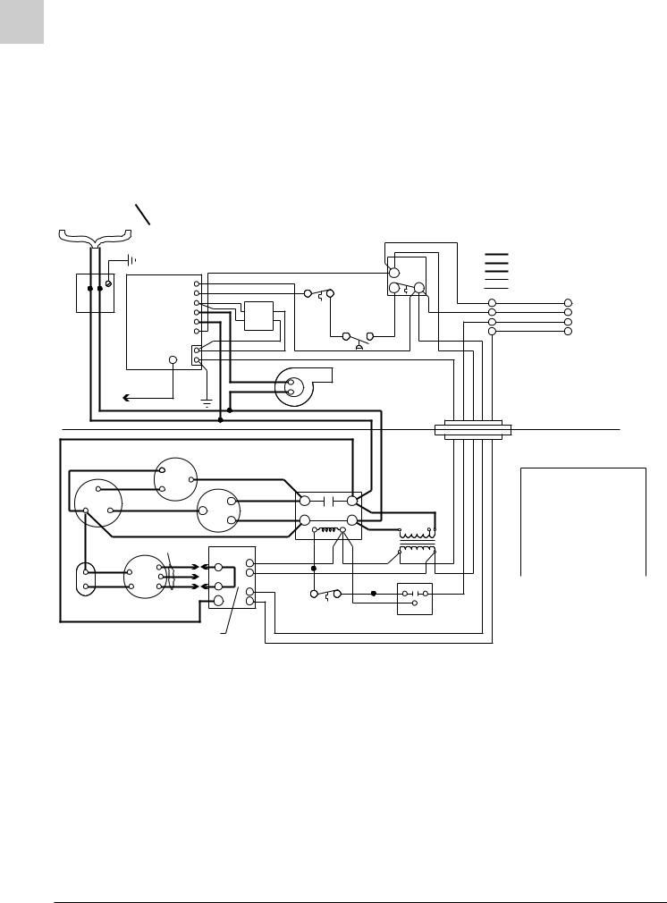
SPECIFICATIONS |
Magic-Pak: HW/HWC |
2-16
HWC122, 182, 242, 302
(w/Fenwal Triton 2461D DSI Ignition Control)
CIRCUITS ENERGIZED
208/230-1-60 |
|
COPPER CONDUCTORS |
|
POWER SUPPLY |
ONLY |
||
|
|
|
|
OPERATING MODE |
CIRCUIT |
HEATING |
R-W |
COOLING |
R-G-Y |
FAN |
R-G |
|
|
|
|
PINK |
MANUAL |
|
NO |
RED |
|
|
|
|
|
|
|
|
LIMIT |
|
|
||||
|
|
TH |
|
|
|
|
|
||||
|
|
WHITE |
RESET |
|
SWITCH NC |
C |
|
|
|||
|
|
P.SW |
|
|
|
|
|||||
|
|
ORN |
|
|
|
|
|
|
|
|
|
|
|
V1 |
|
WHITE |
|
|
|
|
|
R |
|
|
|
ORN |
|
|
|
WHITE |
WHITE |
||||
|
|
IND |
|
|
|
W |
|||||
BLACK BLACK |
|
|
BLUE |
|
|
|
|
||||
|
|
BROWN |
|
|
|
|
|||||
|
|
|
GAS |
|
|
|
|
|
|
||
|
|
L1 |
|
VALVE |
|
PRESSURE |
|
|
|
Y |
|
|
24VAC |
|
BLUE |
|
|
SWITCH |
|
|
|
G |
|
|
|
|
|
|
|
|
|
||||
|
|
|
|
|
|
|
|
|
|
|
|
|
IGNITION |
V2 |
|
|
|
|
|
|
|
|
|
|
CONTROL |
GND |
|
|
|
|
|
|
|
|
|
|
|
GREEN |
RED |
BLACK |
|
COMBUSTION |
BLUE |
GREEN WHITE RED YELLOW |
|||
|
ELECTRODE |
|
|
BLOWER |
|
||||||
|
|
|
BLACK |
|
|
|
|
|
|
|
|
|
CABLE |
|
|
|
|
|
|
|
|
|
|
|
|
|
|
|
|
|
|
|
|
|
|
|
|
|
|
|
BLACK |
|
CONNECTOR |
|
|
||
|
|
|
|
|
BLACK |
|
|
|
|||
|
|
|
|
|
|
|
BLOCK |
|
|
||
|
|
|
|
|
|
|
|
|
|
|
|
|
BLACK |
|
|
|
|
|
|
|
|
|
|
|
CONDENSER FAN |
|
|
|
|
|
|
|
|
|
|
|
|
|
VIOLET |
BLACK |
|
|
|
|
|
|
|
|
|
BLUE |
|
CAPACITOR-RUN |
|
|
|
|
|
|
|
|
|
RED |
|||
FAN |
BROWN |
|
|
BLACK |
|
|
|
|
|
|
|||
|
|
C |
T1 |
L1 |
|
|
|
|
|
||||
COM |
|
|
|
BLACK |
|
|
|||||||
YELLOW |
S |
|
RED |
|
CONTACTOR |
|
|
|
|||||
HERM |
|
|
|
|
|
|
|
||||||
|
R |
|
T2 |
L2 |
BLACK |
|
|
|
|||||
|
|
|
|
|
208V |
|
|
||||||
|
RED |
|
|
|
|
|
|
|
240V |
|
|||
|
|
|
|
|
|
|
TRANS- |
|
|
||||
RED |
SEE TABLE |
|
|
|
|
|
|
|
|
|
|||
|
|
|
|
|
YEL |
FORMER |
|
|
|
||||
FOR WIRING |
BLOWER |
|
|
|
|
|
|||||||
BLK |
CONTROL |
BLUE |
|
BLUE |
|
|
|
|
|||||
YEL |
C |
|
C |
|
|
|
|
|
|
||||
BLK |
|
|
|
RED |
|
|
|
|
|||||
BLUE |
R |
|
|
BLK |
|
|
|
|
|||||
|
|
|
|
|
|
|
|
|
|
||||
|
RED |
H |
|
|
|
BLK |
YEL |
CONTR |
YEL |
|
|||
BROWN |
W |
|
|
|
|||||||||
|
|
|
|
|
|
||||||||
CAPACITY |
BLOWER |
L1 |
|
G |
|
COMP T’STAT |
|
|
|
LOAD |
|
|
|
|
|
BLUE |
|
|
|
|
|||||||
BLOWER |
MOTOR |
|
|
|
|
|
COM |
|
|
||||
|
|
|
|
|
|
(IF USED) |
|
|
TIME DELAY |
|
|||
|
|
|
|
|
|
|
|
|
|
|
|||
|
SEE TABLE |
|
|
|
|
|
WHITE |
(IF USED) |
|
|
|||
|
|
|
|
|
|
GREEN |
|
|
|
|
|||
|
|
|
|
|
|
|
|
|
|
|
|
||
LINE VOLTAGE - FACTORY
LINE VOLTAGE - FACTORY (WHEN USED) LINE VOLTAGE - FIELD
LOW VOLTAGE - FACTORY LOW VOLTAGE - FIELD
R
W THERMOSTAT
Y
G
NOTE:
IF ANY OF THE ORIGINAL WIRES ARE REPLACED, THE SAME SIZE AND TYPE WIRE MUST BE USED.
EVAPORATOR MOTOR
SPEED CONNECTIONS
MODELS |
HEATING |
COOLING |
|
|
26HWC122 |
LOW (RED) |
MED (BLUE) |
|
|
38HWC122 |
HIGH (BLK) |
MED (BLUE) |
|
|
38HWC182 |
LOW (RED) |
LOW (RED) |
* |
|
51HWC182 |
MED (BLUE) |
LOW (RED) |
||
64HWC182 |
HIGH (BLK) |
LOW (RED) |
|
|
38HWC242 |
LOW (RED) |
MED (BLUE) |
|
|
51HWC242 |
MED (BLUE) |
MED (BLUE) |
* |
|
64HWC242 |
HIGH (BLK) |
MED (BLUE) |
||
51HWC302 |
MED (BLUE) |
HIGH (BLK) |
|
|
64HWC302 |
HIGH (BLK) |
HIGH (BLK) |
* |
|
* JUMPER REQUIRED |
||||
|
||||
#39007D5
Note: On units that are equipped with a low ambient switch (designated with an “SA” in the model number), sequence of operation during cooling call is modified when outdoor temperatures fall below the normal operating range. For more information on the low ambient switch equipped version of this unit, see the section beginning on page 2-38.
FIGURE 2-3 Connection Diagram
HW/HWC-SRM
2/99

Service Reference Manual |
SEQUENCE OF OPERATIONS |
2-17
Simplified Sequence - HWC122,182, 242, 302 (w/Fenwal Triton 2461D DSI Ignition Control)
Refer to Figure 2-3
CALL FOR HEAT
1.A call for heat closes the circuit between wires R (red) and W (white) on the unit’s thermostat connections.
2.A low voltage (24 volts) signal is sent to the ignition control, closing a relay which sends line voltage to the induced draft blower. At the same time, a 24volt signal is also sent to the blower control board. This causes the blower control board to begin the countdown to closing the relay that starts the circulating air blower.
3.After the induced draft blower creates enough negative pressure, the pressure switch closes.
4.When the pressure switch closes, the 24-volt signal is sent to the ignition control. This starts a 30second pre-purge countdown, after which a trial for ignition is made.
5.At the same time that the trial for ignition is made, the gas valve energizes and gas flows to the burners.
6.With the burners in operation, the trial for ignition continues for seven seconds. At the end of this time, the ignition control stops sparking.
7.Approximately 30 seconds after the burners ignite, the timer on the blower control board closes a relay, sending line voltage to and starting the circulating air blower.
8.The unit continues to operate as long as there is a 24-volt signal between R and W. When the call for heat is satisfied, the 24-volt signal between R and W discontinues. When W de-energizes, the power to the induced draft blower and the gas valve is interrupted. The 24-volt signal to the blower control board is also interrupted, causing the module to start the countdown to blower “off” (approximately 90 seconds).
9.If at any time during a call for heat the limit switch opens, the 24-volt signal to the white wire going to terminal P.SW on the ignition control is interrupted. This de-energizes the gas valve immediately. The circulating air blower and the induced draft blower continue to run. When the unit cools down enough for the limit switch to close, the 24-volt signal is again sent to the P.SW terminal on the ignition control. With terminal P.SW energized, the ignition control again makes a trial for ignition and relights the burners.
CALL FOR COOLING
1.A call for cooling closes the circuit from R to Y and G.
2.A 24-volt signal is sent to blower control board terminal G and to the compressor contactor. The contactor closes, sending line voltage to the compressor and the outdoor condenser fan.
3.With a 24-volt signal at terminal G on the blower control board, the circulating air blower starts in cooling speed approximately 15 seconds later (or immediately - see note below).
4.When the cooling call is completed, G and Y deenergize. The contactor opens immediately, stopping the compressor and the outdoor cooling fan. When G de-energizes, the timer to turn off the circulating air blower starts. The circulating air blower turns off after 90 seconds (see note below).
FAN ON
1.When the thermostat switch is moved to the “FAN ON” position, the circuit between R and G closes.
2.The 24-volt signal from G goes to the blower control board which starts the timer.
3.Fifteen seconds after terminal G on the blower control board energizes (or immediately after - see note below), the circulating air blower starts.
4.When terminal G on the blower control board deenergizes, the timer to turn off the circulating air blower starts. The circulating air blower turns off after 90 seconds (see note below).
Note: Heatcraft blower control boards have a G “on” delay of 15 seconds and an “off” delay of 90 seconds. Tridelta blower control boards have no “on” time delay and a 60 -130 second “off” delay.
SRM-HW/HWC 2/99
Detailed Sequence follows 

SPECIFICATIONS |
Magic-Pak: HW/HWC |
2-18
Detailed Sequence - HWC122, 182, 242, 302 (w/Fenwal Triton 2461D DSI Ignition Control)
Refer to Figure 2-3
POWER
Line Voltage
When the service disconnect switch is closed, power is sent to the unit (unit in standby, no signal from the thermostat). Power (208 - 230 volts A/C) is supplied to both black wires located in the junction block on top of the unit.
Line voltage will be present at the following locations:
First black wire
1.L-1 on the ignition control
2.L-1 on the contactor
3.L-1 on the blower control board
4.Terminal on the transformer marked 208V or 240V (whichever is being used)
Second black wire
1.Supplies power to the induced draft blower
2.L-2 on the contactor
3.Common terminal on the transformer
4.T-2 on the contactor
5.Red wire on the R terminal of the compressor
6.Red wire to the common terminals on the capacitors
Low Voltage (24 VAC)
With the unit at rest (no call from the thermostat), 24 volts A/C will be found at these points:
1.Red wire exiting the top of the unit
2.Terminal marked 24 VAC on the ignition control
3.Terminal R on the blower control board
CALL FOR HEAT
Line Voltage
The thermostat closes the circuit between R and W.
The following is the sequence of operation for the line voltage side of the unit:
1.Terminal TH (24-volt) energizes on the ignition control, causing the relay in the ignition control to close. This sends line voltage to the terminal marked IND, causing the induced draft blower to start.
2.When W energizes, a 24-volt signal is also sent to the W terminal on the blower control board. The 24-volt signal to the blower control board starts the timer on the board. After 60 seconds, the heat speed relay on the blower control board closes. This sends line voltage from the terminal marked
HEAT to the circulating air blower, starting the blower. The induced draft blower and the circulating air blower continue to operate until the heat call is satisfied, interrupting the circuit between R and W. The W terminal de-energizes, causing the blower relay to open approximately 90 seconds later. This interrupts the line voltage to the circulating air blower and the blower shuts down.
Low Voltage
1.A call for heat closes the circuit in the thermostat between R and W, sending a 24-volt signal to the white wire on the unit.
2.The white wire goes to the C terminal on the limit switch, ignition control terminal TH and terminal W on the blower control board.
3.When W energizes, the timer starts a countdown to blower “on”. The blower starts in approximately 60 seconds.
4.The 24-volt signal sent to terminal TH closes the relay in the ignition control. This starts the induced draft blower by energizing terminal IND on the ignition control.
5.As the induced draft blower comes up to speed and creates enough negative pressure, the pressure switch closes. The 24-volt signal from the pressure switch energizes terminal P.SW, causing the ignition control to start a trial for ignition (sparking).
6.As the trial for ignition starts, the V1 terminal on the ignition control energizes. At the same time, a 24volt signal is sent to the gas valve, opening the valve. The unit continues to operate as long as W is energized.
7.When the call for heat is satisfied, the circuit between R and W is interrupted.
8.With W de-energized, the gas valve closes immediately and the induced draft blower shuts down several seconds later.
9.The blower control board starts a countdown to blower “off”. Approximately 90 seconds later, the blower shuts down.
HW/HWC-SRM
2/99

SRM-HW/HWC 2/99
Service Reference Manual
LIMIT OPENS
If the limit switch opens for any reason during a call for heat, the following happens:
1.If the limit switch senses that the temperature in the unit is too high, the contacts between terminals C and NC on the limit switch open and the contacts between C and NO close. This interrupts the 24-volt signal to the pressure switch and also deenergizes terminal P.SW on the ignition control. The gas valve closes immediately, as the 24-volt signal to terminal P.SW is no longer present. The induced draft blower and the circulating air blower continue to run. Power to blower control board terminal W is maintained. The blowers continue to run until the limit switch closes or the heat call at the thermostat is satisfied.
2.When the limit switch senses that temperatures in the unit are normal, the contacts between terminals C and NO open, the contacts between terminals C and NC close and operation of the unit returns to normal.
PRESSURE SWITCH OPENS (BLOCKED FLUE)
1.If blockage of the flue occurs, the negative pressure in the induced draft blower is reduced. At the set point of the pressure switch, the contacts open.
This interrupts the 24-volt signal to terminal P.SW on the ignition control. The gas valve closes immediately, as the relay in the ignition control opens and interrupts the signal to terminal V2 of the ignition control.
2.Terminal W on the blower control board stays energized and the circulating air blower continues to run. If the negative pressure is restored, the pressure switch closes and sends a 24-volt signal to the P.SW terminal on the ignition control. The ignition control makes a trial for ignition again and operation returns to normal.
Note: If the P.SW and TH terminals energize at the same time, the ignition control will not respond. A pressure switch being stuck closed is an example of what would cause this to happen.
ROLLOUT SWITCH ACTIVATED
1.If the conditions in the burner compartment cause the rollout switch to trip, the contacts on the switch open, interrupting the 24-volt signal going to terminal P.SW on the ignition control. This causes the ignition control to de-energize terminal V1, interrupting the 24-volt signal to the gas valve and immediately closing it.
SEQUENCE OF OPERATIONS
2-19
2.The reason the rollout switch was tripped must be determined before corrective action is taken.
3.The signal to terminal P.SW can only be restored if the rollout switch is reset, which can only be done manually. The W terminal on the blower control board remains energized and the circulating air blower continues to operate. Once the rollout switch is reset, the operation of the unit returns to normal.
CALL FOR COOLING
Line Voltage
On a call for cooling, the thermostat closes the circuit between Y, G and R.
1.With Y energized, the contactor closes. This sends line voltage to compressor terminal C, causing the compressor to start. The outdoor fan also starts, drawing air through the outdoor coil.
2.Terminal G on the blower control board also energizes at the same time as Y. This starts the timer on the blower control board. Approximately 15 seconds later (or immediately - see note on page 2-20), the terminal marked COOL energizes. This sends line voltage to the circulating air blower, starting the blower.
3.The unit continues cooling as long as both Y and G are energized. When the cooling call is satisfied, the circuit between Y, G and R is interrupted. The contactor immediately opens, interrupting power to the compressor and the outdoor cooling fan.
4.With the low voltage signal to terminal G on the blower control board interrupted, the board starts a countdown to blower “off”. After approximately 90 seconds (see note on page 2-20), the cooling speed relay opens and the circulating air blower shuts down.
Low Voltage
1.On a call for cooling, the thermostat closes the circuit between R and terminals G and Y.
2.The 24-volt signal energizes terminal G on the blower control board, starting the fan “on” timer. Approximately 15 seconds later (or immediately - see note on page 2-20), the relay closes. This sends line voltage to the COOLING speed terminal on the blower control board, which starts the circulating air blower.
3.The signal from Y energizes the contactor, starting the compressor and the outdoor cooling fan.
4.When the cooling call is satisfied, both G and Y are de-energized. The contactor opens immediately, causing the compressor and the outdoor cooling fan to stop.

SPECIFICATIONS |
Magic-Pak: HW/HWC |
2-20
5.The circulating air blower shuts off approximately 90 seconds after G terminal on the blower control board is de-energized (see note below).
FAN ON
Low Voltage
1.When the switch on the thermostat is moved to the “FAN ON” position, a 24-volt signal is sent to G.
2.With G energized, the blower control board starts a countdown to fan “on”. After approximately 15 seconds, the fan starts (see note below).
3.The blower control board closes a relay on the board, sending line voltage to the terminal marked COOL on the board. This starts the circulating air blower.
4.When the switch at the thermostat is moved to the “OFF” position, the 24-volt signal to the blower control board is interrupted. With no signal at the
G terminal, the blower control board starts a countdown to fan “off”. Approximately 90 seconds later, a relay on the blower control board opens (see note below). This interrupts the power to and stops the circulating air blower.
Note: Heatcraft blower control boards have a G “on” delay of 15 seconds and an “off” delay of 90 seconds. Tridelta blower control boards have no “on” time delay and a 60 -130 second “off” delay.
HW/HWC-SRM
2/99
Loading...