

Armstrong World Industries HWC PREMIER 302, HWC PREMIER 123, HWC PREMIER 183, HWC PREMIER 243, HWC PREMIER 203 User Manual
...Page 1
Service Reference Manual
HWC Thru-the-Wall Units
Models:
HWC Premier
122, 182, 242, 302
123, 183, 243, 303
Page 2

Copyright © 1998
Armstrong Air Conditioning Inc.
All rights reserved.
Disclaimer
This manual presents information and guidelines for proper installation, adjustment, operation
and maintenance of Armstrong Magic-Pak HW/HWC Thru-the-Wall units. Read this manual
before attempting assembly, installation, start-up, adjustment or operation of the unit. If you have
any questions about the operation of the unit or a particular safety device, call or write Armstrong Air Conditioning Inc., 421 Monroe Street, Bellevue, Ohio USA 44811. Telephone: 419483-4840 Fax: 419-483-3557
The documentation and drawings contained in this manual are intended as a general guide, and
may not reflect exactly the current designs, or all of the options available to our customers.
Please call or write Armstrong Air Conditioning Inc. regarding specific details of a particular
furnace model, configuration or installation.
The information and specifications contained in this manual are subject to change without notice. Armstrong Air Conditioning Inc. reserves the right to change such specifications at any time
without incurring obligation. Every effort has been made to ensure the accuracy of the information in this manual. For the most current information, please contact the Ar mstrong Customer
Service Department.
This document is confidential. All information within is the sole property of Armstrong Air Conditioning Inc. and is loaned for mutual assistance. It may not be used for any purpose other than
originally intended, without prior written consent of Armstrong. It is not intended for use by
homeowners or as a guide for do-it-yourself projects. It provides specialized information for use
by qualified service personnel, who have the proper equipment, training and experience necessary to safely install, repair, adjust and maintain the Magic-Pak units and components described
within.
SRM-HW/HWC 8/99
Page 3

Service Reference Manual TABLE OF CONTENTS
TABLE OF CONTENTS
1 - Specifications
2 - Sequence of Operations
3 - Unit Tear Down
4 - Component Location Illustrations
5 - Unit Components
6 - Installation
7 - Accessories
8 - Parts Lists
9 - Troubleshooting/Performance/
Charge Weights
Go to: If you need information on:
Section 1 Perf ormance, electrical data and cabinet dimensions.
Section 2 Sequence of operation descriptions with accompanying schematics.
Section 3 Complete description of unit disassembly .
Section 4 Locations of major components of HW/HWC models.
Section 5 Illustrations and specifications for individual components including valv es ,
blowers, ignition controls and b lo wer control boards .
SRM-HW/HWC 8/99
Section 6 Installation requirements and startup guidelines.
Section 7 Complete listing of all Armstrong accessories available, including wall
sleeves, louvers and gas conversion kits.
Section 8 Complete service parts lists for all HW and HWC models.
Section 9 System check and troubleshooting procedures .
Page 4

Service Reference Manual SPECIFICATIONS
Section 1 - Specifications
Models Covered By This Manual ............ 1-2
Model Number Guide ............................ 1-2
Product Serial Numbers
(Beginning 1993) ................................. 1-2
Summary of Model Revisions/Variations 1-3
Heating Configuration Table ........................ 1-3
Cooling Configuration Table ......................... 1-3
HW/HWC ............................................ 1-4
Physical and Electrical ................................ 1-4
Performance Ratings .................................. 1-4
Blower Performance ................................... 1-6
Dimensions ................................................ 1-6
Wall Sleeve................................................ 1-7
1-1
SRM-HW/HWC 8/99
Page 5

SPECIFICATIONS Magic-Pak: HW/HWC
1-2
Models Covered By This Manual
HWC Gas Heating/Electric Cooling Units
HW122, 123
HW182,183
HW242, 243
HW302, 303
HW Gas Heating Only Units
26HW
38HW
51HW
64HW
Model Number Guide
HW/HWC Models
26 H W C 12 2 -- 2A
26 = Rated Input BTU/Hr x 1000
H = Gas Heat
W = Thru-the-Wall
C = Cooling
12 = Nominal Cooling BTU/Hr x 1000
2 = Cooling Efficiency 2 - 9.7 SEER
2A = Revision Code
Product Serial Numbers, Beginning 1993
84 95 A 12345
84 = Armstrong Factory Number
95 = Year (ex: 1995)
A = Month (see list below)
12345 = Sequential Number
A = Jan B = Feb C = Mar D = Apr
E = May F = June G = July H = Aug
J = Sept K = Oct L = Nov M = Dec
SRM-HW/HWC 8/99
Page 6

Service Reference Manual SPECIFICATIONS
Summary of Model Revisions/Variations
Table 1-1 Heating Configurations of HW/HWC Units
1-3
ledoMnoitarugifnoCEUFAlortnoCrewolB/noitingI
1-)303,342,381,321(CWH)llA(
9-WH)llA(ylnOtaeHsaG087901lortnoCrewolB/noitingInoitanibmoChceTUISD
)203,242,281,221(CWH)llA(
5-,6-,7-,8-,9-,01-,11-
)203,242,281,221(CWH)llA(
1-,2-,3-,4-
/taeHsaG
/taeHsaG
/taeHsaG
087901lortnoCrewolB/noitingInoitanibmoChceTUISD
looCcirtcelE
08
looCcirtcelE
08
looCcirtcelE
Table 1-2 Cooling Configurations of HWC Units
ledoMnoitarugifnoCegannoTREES*epyTrosserpmoCeciveDgnireteM
1-321CWH)llA(looCcirtcelE/taeHsaG17.9yratoRhesmuceTreirDretliF/ebuTyrallipaC
1-381CWH)llA(looCcirtcelE/taeHsaG5.17.9
noitingI
epyT
D1642notirTlawneF:lortnoCnoitingI
,104C4HCBItfarctaeH:lortnoCrewolB
0101hceTUro8400B029atledirT
92-50lawneF:lortnoCnoitingI
,104C4HCBItfarctaeH:lortnoCrewolB
0101hceTUro8400B029atledirT
hesmuceT
gnitacorpiceR
ISD
ISD
reirDretliF/ebuTyrallipaC
1-342CWH)llA(looCcirtcelE/taeHsaG27.9llorcSdnalepoCreirDretliF/ebuTyrallipaC
1-303CWH)llA(looCcirtcelEtaeHsaG5.27.9llorcSdnalepoCreirDretliF/ebuTyrallipaC
-,11-281CWH)llA(
6-,7-,9
9-,11-242CWH)llA(looCcirtcelE/taeHsaG27.9llorcSdnalepoCreirDretliF/ebuTyrallipaC
-,01-221CWH)llA(
1-,3-,4-,5-,8
-,01-242CWH)llA(
1-,3-,4-,5-,8
9-203CWH)llA(looCcirtcelE/taeHsaG5.25.9llorcSdnalepoCreirDretliF/ebuTyrallipaC
,5-,8-281CWH)llA(
2-,3-,4-
,5-,8-203CWH)llA(
1-,3-,4-
1-281CWH)llA(looCcirtcelE/taeHsaG5.15.9llorcSdnalepoCreirDretliF/ebuTyrallipaC
* For more information on the compressors used in HWC units, see the Unit Components section, beginning on page 5-28.
looCcirtcelE/taeHsaG5.17.9
looCcirtcelE/taeHsaG17.9yratoRhesmuceTreirDretliF/ebuTyrallipaC
looCcirtcelE/taeHsaG27.9llorcSdnalepoCreirDretliF/ebuTyrallipaC
looCcirtcelE/taeHsaG5.17.9yratoRhesmuceTreirDretliF/ebuTyrallipaC
looCcirtcelE/taeHsaG5.25.9llorcSdnalepoCreirDretliF/ebuTyrallipaC
hesmuceT
gnitacorpiceR
reirDretliF/ebuTyrallipaC
SRM-HW/HWC 8/99
Page 7

SPECIFICATIONS Magic-Pak: HW/HWC
1-4
HW/HWC
Physical and Electrical
Table 1-3 Physical and Electrical Specifications - HWC Units
ledoM
/egatloV
esahP/zH
lamroN
egatloV
egnaR
.niM
tiucriC
yticapmA
321/221CWH621/06/032-802352-7913.8510.53.628157019.08/14X016/124523
321/221CWH83 1/06/032-802 352-791 3.8 51 0.5 3.62 81 5701 9.0 8/1 4X01 6/1 24 523
381/281CWH831/06/032-802352-7916.31023.80.548157019.08/14X013/165053
381/281CWH15 1/06/032-802 352-791 6.31 02 3.8 0.54 81 5701 9.0 8/1 4X01 3/1 65 053
381/281CWH461/06/032-802352-7916.31023.80.548157019.08/14X013/165053
342/242CWH63 1/06/032-802 352-791 6.81 52 6.11 5.26 81 5701 8.1 4/1 4X01 3/1 85 063
342/242CWH151/06/032-802352-7916.81526.115.268157018.14/14X013/185063
342/242CWH46 1/06/032-802 352-791 6.81 52 6.11 5.26 81 5701 8.1 4/1 4X01 3/1 85 063
203CWH151/06/032-802352-7914.22036.410.678157018.14/14X013/195083
203CWH46 1/06/032-802 352-791 4.22 03 6.41 0.67 81 5701 8.1 4/1 4X01 3/1 95 083
303CWH151/06/032-802352-7919.12031.410.378157018.14/14X013/195083
303CWH46 1/06/032-802 352-791 9.12 03 1.41 0.37 81 5701 8.1 4/1 4X01 3/1 95 083
Performance Ratings
.xaM
RCAH/esuF
.rkrB
)spma(
.pmoC
detaR
daoL
)spma(
.pmoC
.D.O
dekcoL
naF
rotoR
)spma(
.moN
.aiD
MPR
).ni(
edistuO
naF
detaR
daoL
detaR
PH
)spma(
roodnI
leehW
x.aid
htdiw
rewolB
detaR
PH
.girfeR
egrahC
).zo(
thgieW
).sbl(
).ni(
Table 1-4 Performance Ratings - HWC122/123
Outdoor Air Temperature Entering Outdoor Coil
85°
latoT
Enter.
Wet
Bulb
63°
67°
71°
latoT
riA
0040062102887.29.00.10002101908.59.00.100411000128.59.00.100801090158.00.100.1
0540082102828.79.00.10022101958.00.100.100611000178.00.100.100011090109.00.100.1
0050013102878.00.100.10042101909.00.100.100811000129.00.100.100211090159.00.100.1
0040043102895.47.98.0072101906.67.19.00121010126.97.00.100511011136.18.69.
0540063102826.87.49.0092101946.08.79.00321010156.38.00.100711011176.68.00.1
0050093102856.28.99.0023101976.48.00.100621010196.88.00.100911011107.19.00.1
0040024103804.65.27.0053102904.75.47.00821020114.85.67.00121021114.95.87.
0540044103824.95.67.0073102924.06.87.00031020134.26.08.00321021134.36.28.
0050074103844.26.08.0004102944.36.28.00331020154.56.48.00621021154.66.78.
gnilooC
.loV
yticapaC
)MFC(
)hutB(
taT/S
taT/S
taT/S
.pmoC
°57
sttaW
tupnI
°08
yrD
yrD
bluB
bluB
latoT
°58
yrD
bluB
gnilooC
yticapaC
)hutB(
Note: All values are gross capacities and do not include blower motor heat deduction.
95° 105° 115°
taT/S
taT/S
.pmoC
°57
sttaW
yrD
tupnI
bluB
taT/S
°08
°58
yrD
yrD
bluB
bluB
latoT
gnilooC
yticapaC
)hutB(
taT/S
taT/S
taT/S
.pmoC
°57
sttaW
tupnI
°08
yrD
yrD
bluB
bluB
latoT
°58
yrD
bluB
gnilooC
yticapaC
)hutB(
taT/S
taT/S
.pmoC
°57
sttaW
yrD
tupnI
bluB
taT/S
°08
°58
yrD
yrD
bluB
bluB
SRM-HW/HWC 8/99
Page 8

Service Reference Manual SPECIFICATIONS
Performance Ratings (continued)
Table 1-5 Performance Ratings - HWC182/183
Outdoor Air Temperature Entering Outdoor Coil
85°
Enter.
Wet
Bulb
63°
67°
71°
latoT
riA
05500481073157.09.00.100171074187.29.00.100751055128.69.00.100441046168.69.00.1
00600781083187.39.00.100471084118.69.00.100061065158.00.100.100641056198.00.100.1
05600981093118.69.00.100671094148.99.00.100261075188.00.100.100841066129.00.100.1
05500891014185.27.78.00581015195.47.98.00171006126.87.49.00651007146.08.69.
00600102024106.57.09.00881025126.77.39.00471016146.18.89.00951017166.38.00.1
05600402034126.87.39.00091035146.08.69.00671026166.48.00.100161027186.68.00.1
05500212054104.55.96.00791055104.65.27.00381056114.85.57.00761057114.06.87.
00600512064124.75.27.00002065124.95.57.00681066134.16.87.00071067134.26.18.
05600812074134.95.47.00302075134.06.87.00881076144.36.18.00271077144.46.48.
gnilooC
.loV
yticapaC
)MFC(
)hutB(
taT/S
taT/S
taT/S
.pmoC
°57
sttaW
tupnI
°08
yrD
yrD
bluB
bluB
latoT
°58
yrD
bluB
gnilooC
yticapaC
)hutB(
latoT
Note: All values are gross capacities and do not include blower motor heat deduction.
95° 105° 115°
taT/S
taT/S
taT/S
.pmoC
°57
sttaW
tupnI
°08
yrD
yrD
bluB
bluB
latoT
°58
yrD
bluB
gnilooC
yticapaC
)hutB(
taT/S
taT/S
taT/S
.pmoC
°57
sttaW
tupnI
°08
yrD
yrD
bluB
bluB
latoT
°58
yrD
bluB
gnilooC
yticapaC
)hutB(
taT/S
.pmoC
°57
sttaW
yrD
tupnI
bluB
1-5
taT/S
taT/S
°08
°58
yrD
yrD
bluB
bluB
Table 1-6 Performance Ratings - HWC242/243
Outdoor Air Temperature Entering Outdoor Coil
95° 105° 115°
taT/S
taT/S
.pmoC
°57
sttaW
yrD
tupnI
bluB
taT/S
°08
°58
yrD
yrD
bluB
bluB
Enter.
Wet
Bulb
63°
67°
71°
85°
latoT
latoT
riA
00700342078147.88.00.100232011267.98.00.100812083287.49.00.100012017208.59.00.1
00800742078187.39.00.100632011208.49.00.100222083228.99.00.100312017248.00.100.1
00900252088128.89.00.100142021258.99.00.100622093278.00.100.100712027298.00.100.1
00700952098175.17.58.00742031285.27.68.00632004295.57.19.00422057206.67.29.
00800362098106.57.09.00152031216.67.19.00042004226.97.69.00822057236.08.79.
00900862009136.97.59.00652041246.08.69.00542014266.48.00.100232067276.58.00.1
00700372019104.55.96.00162051204.55.07.00942034204.65.27.00732077204.75.47.
00800772019124.85.37.00562051224.85.47.00352034224.95.67.00142077224.06.87.
00900382029144.16.77.00072061244.16.87.00852044244.26.08.00642087244.36.28.
gnilooC
.loV
yticapaC
)MFC(
)hutB(
taT/S
taT/S
taT/S
.pmoC
°57
sttaW
tupnI
°08
yrD
yrD
bluB
bluB
latoT
°58
yrD
gnilooC
bluB
yticapaC
)hutB(
Note: All values are gross capacities and do not include blower motor heat deduction.
Table 1-7 Performance Ratings - HWC302/303
Outdoor Air Temperature Entering Outdoor Coil
95° 105° 115°
taT/S
taT/S
.pmoC
°57
sttaW
yrD
tupnI
bluB
taT/S
°08
°58
yrD
yrD
bluB
bluB
Enter.
Wet
Bulb
63°
67°
71°
85°
latoT
latoT
riA
57700582051227.48.79.00372093237.78.00.100162076247.98.00.100842099267.09.00.1
05800982061247.78.00.100672004267.09.00.100462086277.39.00.10015200039739.00.1
52900392071277.09.00.100082014297.39.00.100862096208.69.00.100452010328.69.00.1
57700403091265.96.28.00092044275.17.48.00872027285.37.88.00462050395.37.88.
05800803002285.17.58.00492054295.37.78.00182037206.57.19.00762060316.67.19.
52900213012206.37.78.00892064216.67.09.00582047226.87.49.00172070336.97.49.
57700223022204.45.86.00803084214.55.96.00392067214.65.17.00082090324.75.37.
05800623032214.65.07.00213094224.75.17.00792077224.85.37.00382001334.95.57.
52900033042224.75.27.00613005234.85.37.00103087234.06.67.00782011354.16.87.
gnilooC
.loV
yticapaC
)MFC(
)hutB(
taT/S
taT/S
taT/S
.pmoC
°57
sttaW
tupnI
°08
yrD
yrD
bluB
bluB
latoT
°58
yrD
bluB
gnilooC
yticapaC
)hutB(
latoT
gnilooC
yticapaC
)hutB(
latoT
gnilooC
yticapaC
)hutB(
taT/S
taT/S
taT/S
.pmoC
°57
sttaW
tupnI
.pmoC
sttaW
tupnI
°08
yrD
yrD
bluB
bluB
taT/S
taT/S
°57
°08
yrD
yrD
bluB
bluB
latoT
°58
yrD
bluB
°58
yrD
bluB
gnilooC
yticapaC
)hutB(
taT/S
latoT
gnilooC
yticapaC
)hutB(
taT/S
taT/S
.pmoC
°57
sttaW
yrD
tupnI
bluB
taT/S
.pmoC
°57
sttaW
yrD
tupnI
bluB
taT/S
°08
°58
yrD
yrD
bluB
bluB
taT/S
taT/S
°08
°58
yrD
yrD
bluB
bluB
Note: All values are gross capacities and do not include blower motor heat deduction.
SRM-HW/HWC 8/99
Page 9
SPECIFICATIONS Magic-Pak: HW/HWC
1-6
Blower Performance
Table 1-8 Blower Performance - HWC Units
Model
HWC122/123
HWC182,242,302
HWC183,243,303
Blower Speed
0.2 0.3 0.4 0.5
iH056516575045
deM574054524004
woL514504093083
iH 578 528 577 527
deM 058 508 067 017
woL 036 506 575 055
CFM @ ext. static pressure - in. w.c. with filter(s)
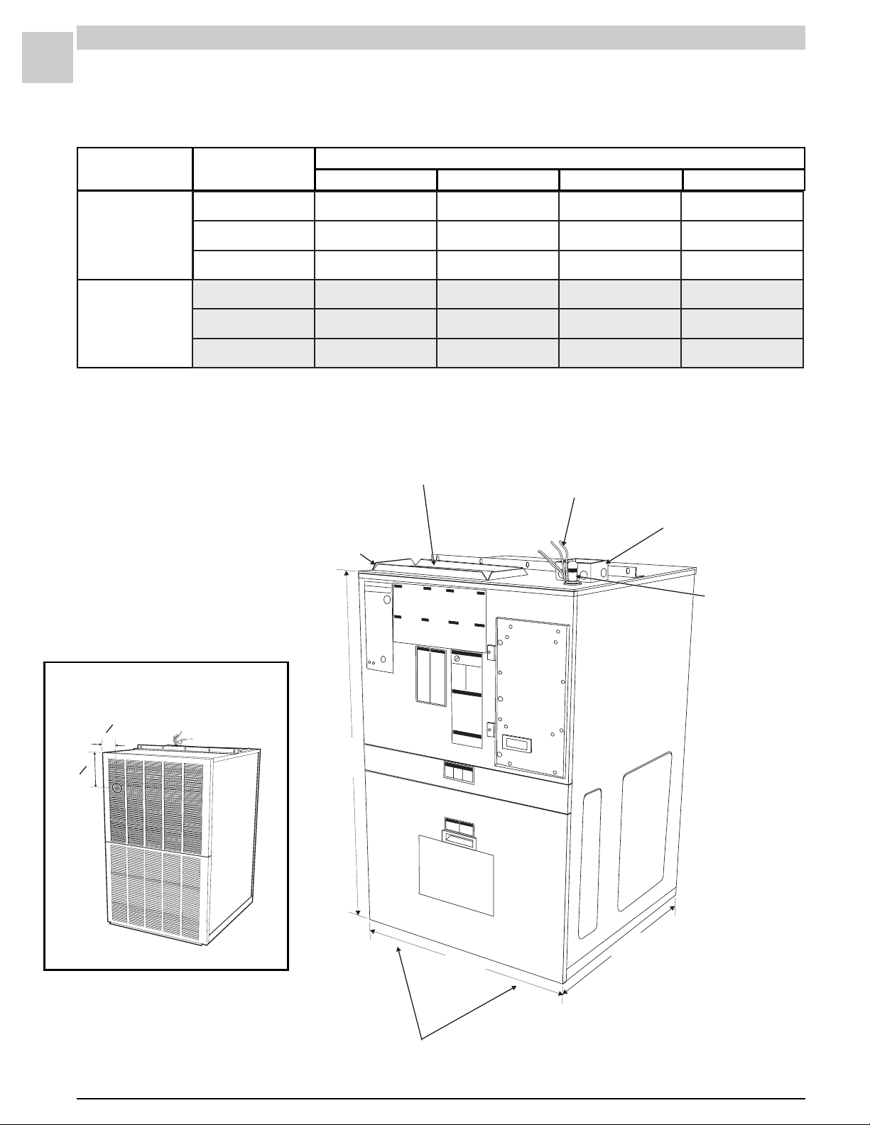
Dimensions (all measurements in inches)
SUPPLY AIR DUCT CONNECTION
8" x 16"
¾" DUCT CONNECTION FLANGE
LOW VOLTAGE
THERMOSTAT CONNECTIONS
HIGH VOLTAGE
JUNCTION BOX
4" x 4" x 2"
Measurements from Side and
Top to Center of V ent Outlet
1
"
4
2
3
"
4
6
GAS LINE
CONNECTION
"
8
/
1
43
"
7
16
/
27
7
/
"
8
29
RETURN AIR OPENING ON BOTTOM
6" x 22"
SRM-HW/HWC 8/99
Page 10
Service Reference Manual SPECIFICATIONS
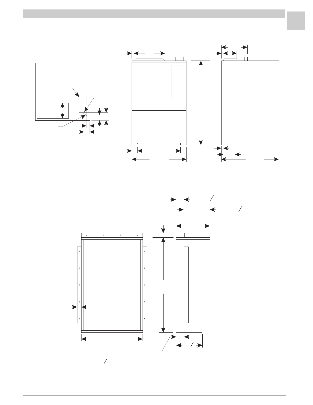
Dimensions (cont.)
3
/
8
13
11
8
Line Voltage
Box
Supply
½ Gas Inlet
16
Supply
Low
Voltage
1
/
8
43
8
7
4
/
8
2
3
/
4
1
3
Return
1-7
7
/
8
2
27
22
7
/
8
Wall Sleeve (all measurements in inches)
2
45
1 or 3
16
1
3
4
6
15 or 12
7
/
16
29
1
4
SRM-HW/HWC 8/99
2
29
12
1
"
2
Flanges may be assembled
3
"
1" or 3 from this side of the sleeve
4
Page 11

Service Reference Manual SEQUENCE OF OPERATIONS
Section 2 - Sequence of Operation
HWC123,183,243,303........................ 2-4
Simplified Sequence ........................................ 2-5
Detailed Sequence .......................................... 2-6
POWER ...................................................................... 2-6
CALL FOR HEAT ........................................................ 2-6
LIMIT/ROLLOUT OPENS ........................................... 2-7
PRESSURE SWITCH OPENS (BLOCKED FLUE)..... 2-7
FAILED FLAME SENSE/TRIAL FOR IGNITION......... 2-8
CALL FOR COOLING................................................. 2-8
FAN ON....................................................................... 2-9
HW (Heating Only)
(w/UTEC 1097 Spark Ignition System) 2-10
Simplified Sequence ...................................... 2-11
Detailed Sequence ........................................ 2-12
POWER .................................................................... 2-12
CALL FOR HEAT ...................................................... 2-12
LIMIT/ROLLOUT OPENS ......................................... 2-13
PRESSURE SWITCH OPENS (BLOCKED FLUE)... 2-13
FAILED FLAME SENSE/TRIAL FOR IGNITION....... 2-14
FAN ON..................................................................... 2-14
2-1
HWC122,182,242,302
(w/Fenwal 2461D Ignition Control) ..... 2-16
Simplified Sequence ...................................... 2-17
Detailed Sequence ........................................ 2-18
POWER .................................................................... 2-18
CALL FOR HEAT ...................................................... 2-18
LIMIT OPENS ........................................................... 2-19
PRESSURE SWITCH OPENS (BLOCKED FLUE)... 2-19
ROLLOUT SWITCH ACTIVATED.............................. 2-19
CALL FOR COOLING............................................... 2-19
FAN ON..................................................................... 2-20
HW (Heating Only)
(w/Fenwal 2461D Ignition Control) ..... 2-22
Simplified Sequence ...................................... 2-23
Detailed Sequence ........................................ 2-24
POWER .................................................................... 2-24
CALL FOR HEAT ...................................................... 2-24
LIMIT OPENS ........................................................... 2-25
PRESSURE SWITCH OPENS (BLOCKED FLUE)... 2-25
ROLLOUT SWITCH ACTIVATED.............................. 2-25
SRM-HW/HWC 2/99
Page 12

2-2
SPECIFICATIONS Magic-Pak: HW/HWC
HWC122,182,242,302
(w/Fenwal 05-29 Ignition Control) ....... 2-26
Simplified Sequence ...................................... 2-27
Detailed Sequence ........................................ 2-28
POWER .................................................................... 2-28
CALL FOR HEAT ...................................................... 2-28
FLAME SENSE......................................................... 2-29
LIMIT OPENS ........................................................... 2-29
ROLLOUT SWITCH ACTIVATED.............................. 2-29
CALL FOR COOLING............................................... 2-29
FAN ON..................................................................... 2-30
HW (Heating Only)
(w/Fenwal 05-29 Ignition Control) ....... 2-32
Simplified Sequence ...................................... 2-33
Detailed Sequence ........................................ 2-34
POWER .................................................................... 2-34
CALL FOR HEAT ...................................................... 2-34
FLAME SENSE......................................................... 2-35
LIMIT OPENS ........................................................... 2-35
ROLLOUT SWITCH ACTIVATED.............................. 2-35
HWC123,183,243,303
w/Low Ambient Control ...................... 2-36
HWC122,182,242,302
w/Low Ambient Control ...................... 2-38
SRM-HW/HWC 2/99
Page 13

Service Reference Manual SEQUENCE OF OPERATIONS
BLANK PAGE
2-3
SRM-HW/HWC 2/99
Page 14
2-4
SPECIFICATIONS Magic-Pak: HW/HWC
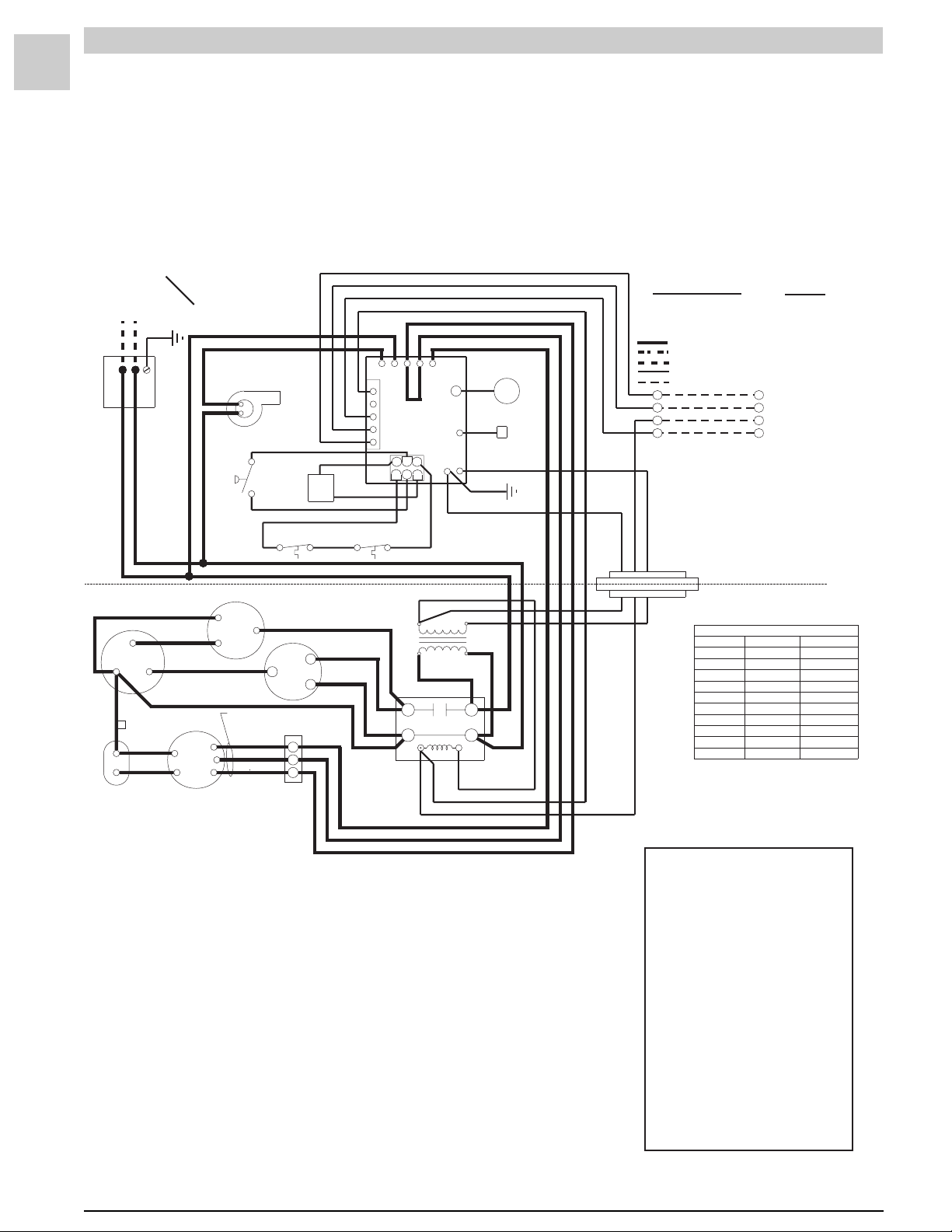
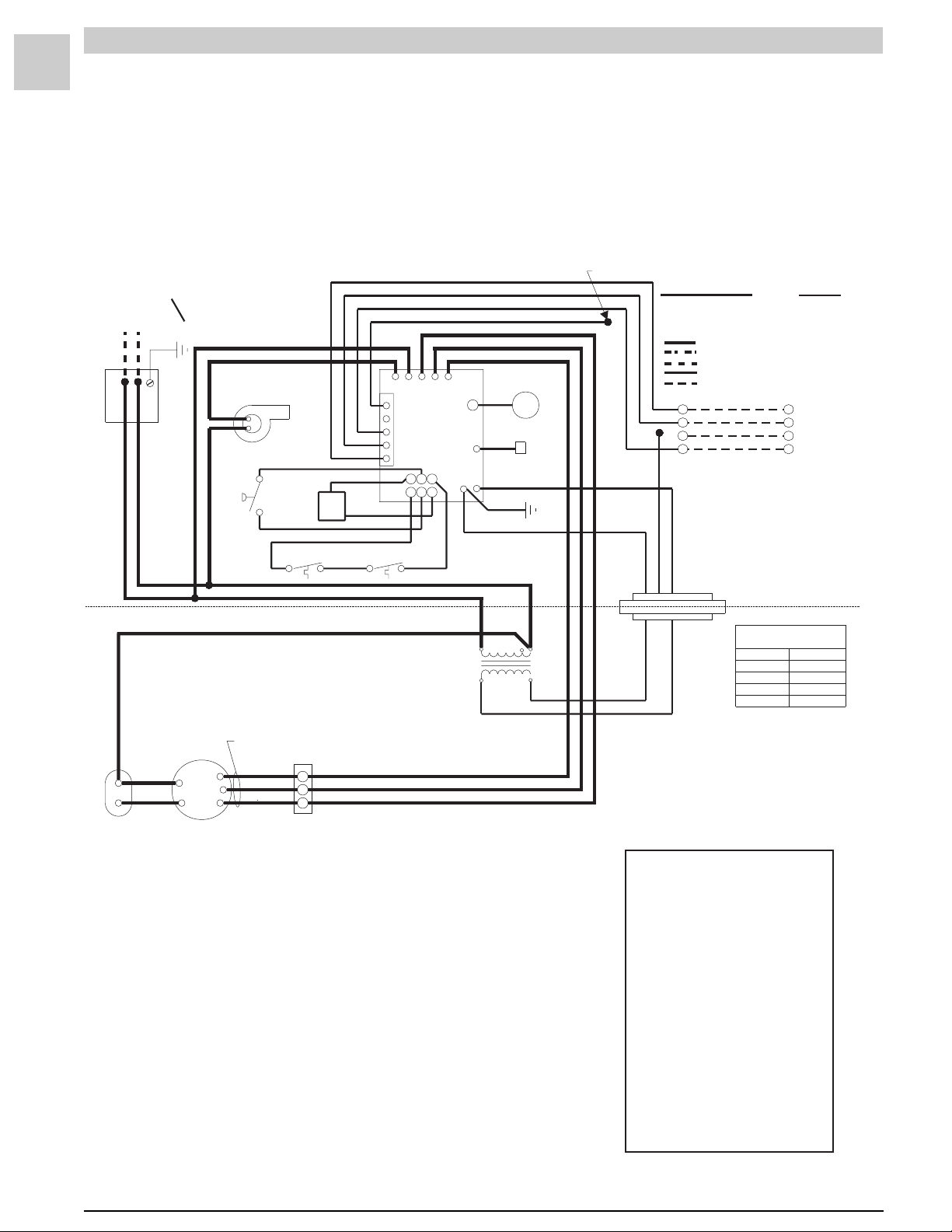
HWC123, 183, 243, 303
(w/United Technologies 1097 Spark Ignition System)
208/230-1-60
POWER SUPPLY
}
BLACK
BLACK
CAPACITOR-RUN
FAN
COM HERM
RED
D
YELLOW
BROWN
CAPA CIT ORCAPA CIT OR
BLOWER
COPPER CONDUCTORS
VIOLET
BROWN
YELLOWYELLOW
RED
BLOWER
MOTOR
ONLY
BLACK BLACK
COMBUSTION
BLOWER
BLACK
CONDENSER FANCONDENSER FAN
SEE
FORWIRING
SWITCH
CHARTCHART
BLACK
BLUEBLUE
RED
VIOLET
PRESSURE
VIOLET
AUTO RESET
LIMIT SWITCH
S
COMP
H
M
L
RED
GAS
VALVE
ORN
ORN
BLACK
C
R
BLOWER
BLOWER
CONTROL
CONTROL
GREEN
WHITE
RED
BLUE
MANUAL RESET
LIMIT SWITCH
BLACK
RED
CONNECTION DIAGRAMCONNECTION DIAGRAM
YELLOW
RED
BLUE
COOL
HEAT
IGNITION
CONTROLCONTROL
5
6
2
3
ORN
208 V
CONTACTOR
T1
T2
BLACK
UNUSED
24VAC
GND
RED
BLACK
TRANSFORMERTRANSFORMER
240 V
BLK
ELECTRODE
WHT
FLAME ROD
GREEN
BLK
L1
L2
BLUE
YELLOW
CMB
1
2
3
4
5
L1
BLACK
RGWCY
4
1
BLUE
RED
CIRCUITS ENERGIZED
OPERATING MODE CIRCUIT
HEATING R-W
COOLING R-G-Y
FAN R-G
LINE VOLT A GE-FACTORY
LINE VOLTAGE-FA CTORYWHEN USED
LINE VOLTAGE-FIELD
LOWVOLTAGE-FACTORY
LOWVOLTAGE-FIELD
R
G
Y
W
NOTE:
IF ANY OF THE ORIGINAL
WIRES ARE REPLACED,THE
BLUE
YELLOW
RED
SAME SIZE AND TYPE WIRE
MUST BE USED.
CONNECTORCONNECTOR
BLOCKBLOCK
EVAP. MOTOR SPEED CONNECTIONSEVAP.MOTOR SPEED CONNECTIONS
JUMPER REQUIRED
*
R
G
Y
}
W
THERMOST AT
COOLINGCOOLINGHEATINGHEATINGMODELSMODELS
MED (BLUE)MED (BLUE)LOW (RED)26HWC12326HWC123
MED (BLUE)MED (BLUE)HIGH(BLACK)HIGH(BLACK)38HWC12338HWC123
LOW (RED)LOW (RED)LOW (RED)38HWC183
LOW (RED)LOW (RED)MED (BLUE)51HWC18351HWC183
LOW (RED)LOW (RED)HIGH(BLACK)HIGH(BLACK)64HWC18364HWC183
MED (BLUE)MED (BLUE)LOW (RED)38HWC24338HWC243
MED (BLUE)MED (BLUE)MED (BLUE)51HWC24351HWC243
MED (BLUE)MED (BLUE)HIGH(BLACK)HIGH(BLACK)64HWC24364HWC243
HIGH(BLACK)MED (BLUE)51HWC30351HWC303
HIGH(BLACK)HIGH(BLACK)HIGH(BLACK)64HWC30364HWC303
*
*
*
#45004-1
Note: On units that are equipped with a low ambient switch (designated
with an “SA” in the model number), sequence of oper ation during
cooling call is modified when outdoor temperatures fall below the
normal operating range. F or more inf ormation on the low ambient
switch equipped version of this unit, see the section beginning on
page 2-36.
FIGURE 2-1 Connection Diagram
The following blower/ignition control board
DIAGNOSTICS
LED codes will indicate normal or abnormal
operations:
SLOW FLASH Normal Operation, No
FAST FLASH Normal Operation, Call for
2 FLASH System Lockout - Failed to
3 FLASH Pressure Switch Open or
4 FLASH High Limit or Rollout
5 FLASH Flame Sensed and Gas
STEADY Internal Failure
Call for Heat
Heat
Detect or Sustain Flame
Closed
Switch Open
Valve Not Energized
(Micro-controlle r Failure;
Self-check)
SRM-HW/HWC 2/99
Page 15

Service Reference Manual SEQUENCE OF OPERATIONS
Simplified Sequence - HWC123,183, 243, 303
Refer to Figure 2-1
2-5
• 208/230V power is supplied to the junction box on
top of the unit
• 24V power is supplied from the unit transformer to
the thermostat
CALL FOR HEAT
1. The thermostat closes the R-W circuit, sending a
24-volt signal to the unit.
2. The 24-volt signal energizes the combustion b low er,
causing the pressure switch to close.
3. The combustion blow er runs f or 30 seconds as a
pre-purge to trial for ignition.
4. The ignition control energizes the spark ignition and
opens the gas valve, causing the b urners to light.
When the gas valve energizes , a 30-second circulating air blower “on” dela y begins .
5. Flame sense is sent to the ignition control through
the flame sensor and flame sense wire.
6. After the 30-second delay, the circulating air blower
energizes and runs until the heat call is satisfied.
7. When the heat call is satisfied, the gas valve deenergizes. This shuts down the burners.
8. A 5-second combustion blow er post-purge dela y
and a 120-second circulating air blower “off” delay
start.
9. After the delay times elapse, the combustion b lo w er
and the circulating air blower stop .
CALL FOR COOLING
1. The thermostat energizes the R, Y and G circuit,
sending a 24-volt signal to the cooling contactor and
the ignition control to start the cooling sequence.
2. The contactor closes immediately, causing the
compressor and the condenser fan to run.
3. The 24-volt Y signal starts a 5-second circulating air
blower “on” delay .
4. After 5 seconds, the circulating air blower starts and
runs until the R, Y and G circuit is interrupted by the
thermostat.
5. When the R, Y and G circuit is interrupted, the
cooling contactor immediately de-energizes. This
causes the compressor and the condenser fan to
stop.
6. The ignition control starts a 90-second circulating
air blower “off” delay.
7. After 90 seconds, the circulating air blower stops .
FAN ON
1. The thermostat energizes the R-G circuit, causing
the circulating air blower to energize in cooling
speed.
2. The circulating air blower remains running in cooling
speed until the thermostat is switched to the “A UTO”
position.
FLAME SENSE
1. After the burners have been lit, the ignition control
starts a 10-second trial for ignition delay .
2. If after 10 seconds a flame has not been sensed by
the ignition control, the ignition control de-energizes
the gas valve and the spark ignitor .
3. The unit initiates three trials for ignition (flame
sense) before system lock out.
4. System lockout lasts 60 minutes or until po wer is
reset to unit (whichever comes first).
SRM-HW/HWC 2/99
Detailed Sequence follows
Page 16

2-6
SPECIFICATIONS Magic-Pak: HW/HWC
Detailed Sequence - HWC123, 183, 243, 303
Refer to Figure 2-1
POWER
Line Voltage
With the unit at rest (no call from the thermostat), line
voltage will be present:
L1 Power
1. Through the L1 black lead to the L1 terminal on the
ignition control
2. At the L1 contactor terminal
3. At the transformer terminal marked 208-240V
L2 Power
1. Through the L2 black lead to the induced draft
blower
2. At the L2 contactor terminal
3. A transformer common terminal
4. At the T2 contactor terminal
5. At the R terminal of the compressor
6. At the capacitor common terminals
Low Voltage (24 VAC)
With the unit at rest (no call from the thermostat), 24
volts A/C will be present:
control. This causes the combustion blower to
start by completing the line voltage circuit through
the L2 wire connection in the unit.
2. As the 24-volt signal is sent to pin 4 of the 6-pin
ignition wire harness by the ignition control, a 30-
second circulating air blower “on” dela y starts.
After the delay, the ignition control energizes the
heat speed blower relay. This sends L1 power to the
ACB HEAT terminal on the ignition control.
3. L1 power is then sent to the circulating air blower
terminal block where it is connected to the blower
motor. The circulating air blower starts by
completing the L1-L2 circuit through the L2 connection at the blower motor capacitor.
4. The combustion blower and the circulating air
blower continue to run until the R-W circuit is
interrupted. After a 5-second post-purge dela y, the
CMB BLWR terminal on the ignition control deenergizes. This interrupts L1 pow er to the combus-
tion blower. After a 120-second circulating air
blower “off” delay, the ACB HEAT terminal de-
energizes. This interrupts L1 to the circulating air
blower. As L1 pow er is interrupted, the blo wers
shut off.
Low Voltage
1. From the transformer 24V terminal to pin 4 of the
6-pin chassis low voltage harness
2. From pin 4 of the chassis low v oltage harness to the
24VAC hot terminal on the ignition control
3. From the 24VAC hot terminal to pin 5 of the 5-pin
thermostat harness (internal to board)
4. From the 24VAC hot terminal also to pin 6 of the 6-
pin ignition wire harness
5. From pin 6 of the ignition wire harness through the
auto reset limit switch and the manual reset
rollout switch to pin 1 of the 6-pin ignition wire
harness
Note: While the unit is at rest, the green LED shows
consistent slow flash. This indicates normal
operation - system at rest (standby mode).
CALL FOR HEAT
Line Voltage
The ignition control receives a signal from the R-W
circuit indicating a call for heat.
1. The combustion blower relay energizes, sending
L1 power to CMB BLWR terminal on the ignition
1. A call for heat closes the R-W circuit, sending a 24volt signal to the low v oltage white wire in the unit.
2. The 24-volt signal is received at pin 3 of the 5-pin
thermostat harness on the ignition control.
3. The 24-volt signal causes the combustion blower
relay to close, causing the combustion blower to
run. At this time, a 24-v olt signal is also sent out
through pin 2 of the 6-pin ignition wire harness.
4. The 24-volt signal from pin 2 of the 6-pin ignition
wire harness energizes one side of the Normally
Open pressure switch. As the induced draft
blower reaches full speed, the pressure switch
closes and a 24-volt signal is sent to pin 5 of the 6pin ignition wire harness.
5. When the 24-volt signal is received at pin 5 of the 6pin ignition wire harness, the ignition control starts
a 30-second pre-purge delay.
6. After the 30-second pre-purge, the ignition control
initiates a trial for ignition. The spark ignition
cable terminal and pin 4 of the 6-pin ignition wire
harness energize simultaneously .
7. When the 24-volt signal is present at pin 4 of the 6pin ignition wire harness, the ignition control starts
a 30-second circulating air blower “on” delay.
8. The 24-volt signal from pin 4 of the 6-pin ignition
wire harness is received at the gas valve, causing
it to open and the burners to ignite.
SRM-HW/HWC 2/99
Page 17

Service Reference Manual SEQUENCE OF OPERATIONS
9. After 30-second “on” delay, the circulating air
blower relay energizes the heat terminal and the
circulating air blower is energized.
10. The unit will continue to operate normally until the
R-W circuit is interrupted.
11. When the heat call is satisfied, the thermostat will
interrupt the R-W circuit. This causes the 24-volt
signal to the white wire in the unit to be de-energized.
12. The gas valve closes immediately as 24V through
pin 4 of the 6-pin ignition wire harness is deenergized by the ignition control.
13. The ignition control initiates a 120-second circu-
lating air blower “off” delay and 5-second com-
bustion blower post-purge delay.
14. After 5 seconds, the combustion blower shuts off.
15. After 120 seconds, the circulating air blower
shuts off and the system returns to standby mode.
Note: During a call for heat, the green LED shows
consistent fast flash (as long as the R-W circuit is
closed). When the R-W circuit is interrupted
(indicating the heat call has been satisfied), the
green LED returns to a consistent slow flash.
LIMIT/ROLLOUT OPENS
In all modes of operation, 24V AC is supplied to the
ignition control 24VAC hot terminal and is passed
through the ignition control to pin 6 of the 6-pin
ignition wire harness.
1. A 24-volt signal is sent from pin 6 of the 6-pin
ignition wire harness to one side of the Normally
Closed manual reset rollout switch, across the
rollout switch to one side of the Normally Closed
auto reset limit switch and across the limit switch
to pin 1 of the 6-pin ignition wire harness.
2. This circuit energizes whenever line v oltage po wer
is supplied to the unit.
3. If the circuit is interrupted by either switch opening,
the 24-volt signal to pin 1 of the 6-pin ignition wire
harness de-energizes.
4. This causes the combustion blower relay to
energize, sending L1 power to the CMB BLWR
terminal on the ignition control. It also causes the
circulating air blower heat speed relay to energize, sending L1 power to the ACB HEAT terminal
on the ignition control. This causes both blowers
to start immediately.
5. The ignition control lockouts the spark ignition
cable terminal and pin 4 of the 6-pin ignition wire
harness until the 24-volt signal is restored at pin 1 of
the 6-pin ignition wire harness.
6. The circulating air blower and the combustion
blower are energized until the 24-volt signal is
restored at pin 1 of the 6-pin ignition wire harness.
7. The green ignition control LED shows a 4 flash fault
code (indicating limit switch/rollout switch open).
8. When the 24-volt signal is restored at pin 1 of the 6pin ignition wire harness, the ignition control starts
a 5-second combustion blower post-purge delay
and a 120-second circulating air blower “off”
delay .
9. Once the delays hav e timed out, both b low ers stop
and the green LED flashes a consistent slow flash if
no heat call is present. (A consistent fast flash
appears if there is a call for heat.)
Note: The limit switch resets automatically when
temperatures are acceptable, b ut the rollout
switch must be manually reset by pushing in on
the small button on top of the switch.
The reason why the switches opened must be
determined before any corrective action is taken.
PRESSURE SWITCH OPENS (BLOCKED FLUE)
When the R-W circuit is energized, a 24-volt signal is
sent to the ignition control. This starts the call for
heat.
1. The 24-volt signal from the R-W circuit energizes
the combustion blower relay, sending L1 power to
the CMB BLWR terminal on the ignition control.
This starts the ignition control.
2. At the same time the combustion blower relay
energizes, the 24-volt signal is sent to pin 2 of the 6pin ignition wire harness and from pin 2 to one side
of the Normally Open pressure switch.
3. When the combustion blower causes the pres-
sure switch to close, a 24-volt signal is sent across
the switch to pin 5 of the 6-pin ignition wire harness.
The 24-volt signal energizes at pin 5 and the ignition
sequence continues.
4. If the combustion blower fails to close the pres-
sure switch, the 24-volt signal is not sent to pin 5
of the 6-pin ignition wire harness and the ignition
control does not initiate a 30-second pre-purge
delay.
5. No signal is sent to the spark ignition cable
terminal on the ignition control or to the gas valve
through pin 4 of the 6-pin ignition wire harness.
6. The combustion blower continues to run for 60
seconds. After 60 seconds, the ignition control
automatically de-energizes the combustion
blower relay. This interrupts L1 pow er to the CMB
BLWR terminal on the ignition control.
7. The combustion blower remains de-energized for
approximately six minutes. During this 6-minute
lockout, the green LED flashes three times (indicating pressure switch fault—open or closed).
2-7
SRM-HW/HWC 2/99
Page 18

2-8
SPECIFICATIONS Magic-Pak: HW/HWC
8. The 24-volt signal will only be supplied to the limit
switch circuit through pin 6 of the 6-pin ignition wire
harness and to the pressure switch circuit through
pin 2 of the 6-pin ignition wire harness.
9. The system will repeat this sequence until the
pressure switch closes and the 24-v olt signal is
restored at pin 5 of the 6-pin ignition wire harness.
FAILED FLAME SENSE/TRIAL FOR IGNITION
When the pressure switch closes and a 24-v olt signal
is sent to pin 5 of the 6-pin ignition wire harness, the
spark ignition cable terminal and pin 4 of the 6-pin
ignition wire harness energize.
1. As spark voltage is supplied to the ignitor elec-
trodes, the gas valve opens and this causes the
burners to ignite.
2. The ignition control continues to energize spark
voltage until a flame sense signal is supplied to the
flame terminal on the ignition control.
3. If a flame sense signal is not received at the flame
terminal on the ignition control, the spark igni-
tion cable terminal remains energized for 10
seconds.
4. After the 10-second trial for ignition, the ignition
control de-energizes the spark ignition cable
terminal and pin 4 of the 6-pin ignition wire harness.
This causes the gas valve to close and the electrode spark to stop.
5. Once the 24-volt signal is sent to pin 4 of the 6-pin
ignition wire harness, a 30-second circulating air
blower “on” delay starts. After the dela y is timed
out, the circulating air blower starts.
6. After the spark ignition cable terminal de-energizes, the ignition control initiates a 30-second
combustion blower inter-purge delay.
7. After 30-second inter-purge, the ignition control
energizes the spark ignition cable terminal and
pin 4 of the 6-pin ignition wire harness. If the flame
sense signal is received at the flame terminal of the
ignition control, the unit continues heat call.
8. If the flame sense signal is not received, the system
goes through three trials following the abov e
sequence.
9. After three trials, the system goes into lockout and
only the high limit switch circuit and pressure
switch circuit remain energized during the 60minute lockout period.
10. If the flame sense is lost during the heat cycle, the
gas valve de-energizes immediately and the
system goes into the trial sequence.
CALL FOR COOLING
Line Voltage
1. L2 power passes through the fix ed closed L2-T2
terminals on the contactor to the RUN terminal of
the compressor and the COMMON terminal of the
capacitor.
2. L1 power is sent to the L1 terminal of the contactor.
When the Y signal energizes the contactor, the T2
terminal becomes energized. L1 pow er is sent to
the compressor COMMON terminal and the
condenser fan. This energizes the compressor
and condenser fan motors.
3. When pin 1 (Y terminal) of the 5-pin thermostat
harness receives a 24-volt signal from the thermo-
stat, a 5-second circulating air blower delay
starts.
4. After the 5-second delay, the ignition control
energizes the cooling speed relay. This sends L1
power to the ACB COOL terminal of the ignition
control.
5. L1 power is sent to the circulating air blower
terminal block, energizing the circulating air
blower motor.
6. When the R, Y and G circuit is interrupted by the
thermostat, the contactor is immediately de-
energized. This interrupts L1 power to the com-
pressor and condenser fan motors, stopping
both.
7. The ignition control starts a 90-second circulat-
ing air blower “off” delay, after which the ACB
COOL terminal de-energizes. This interrupts L1
power to the circulating air blower motor, causing
it to stop.
Low Voltage
1. The thermostat energizes the R, Y and G circuit,
sending a 24-volt signal to the contactor coil and to
pin 1 of the 5-pin thermostat harness connected to
the ignition control.
2. The contactor closes immediately upon receiving
the 24-volt signal, causing the compressor and
condenser fan motors to start.
3. The 24-volt signal is also sent to pin 1 of the 5-pin
thermostat harness, initiating a 5-second circulat-
ing air blower “on” delay.
4. After the 5-second delay, the ignition control
energizes the cooling speed relay and the circulat-
ing air blower starts.
5. When the cooling call is satisfied, the thermostat
interrupts the R, Y and G circuit. The contactor
de-energizes immediately, causing the compressor
and the condenser fan to stop. The ignition
control starts a 90-second circulating air blower
“off” delay.
SRM-HW/HWC 2/99
Page 19

Service Reference Manual SEQUENCE OF OPERATIONS
6. After the 90-second delay, the ignition control deenergizes the cooling speed relay and the circulat-
ing air blower stops.
FAN ON
1. When the thermostat is switched to the “FAN ON”
position, the R-G circuit sends a 24-volt signal to
pin 4 of the 5-pin thermostat harness.
2. The 24-volt signal energizes the cooling speed
relay, sending L1 power to the ACB COOL terminal
of the ignition control.
3. L1 power is sent to the circulating air blower
terminal block, causing the circulating air blower
to run in cooling speed.
4. The circulating air blower continues to run in
cooling speed until the thermostat is switched to
“AUT O”, interrupting the R-G circuit.
Note: With the thermostat in the “FAN ON” position
during heat call, ignition control will not energize
the heat speed relay. The circulating air blower
continues to run in cooling speed unless the limit
switch circuit opens, which would cause the heat
speed relay and the induced draft blower relay
to become energized. This would de-energize the
cooling speed relay until either the limit switch
circuit is closed or the thermostat is switched to
the “AUT O” position.
2-9
SRM-HW/HWC 2/99
Page 20
2-10
SPECIFICATIONS Magic-Pak: HW/HWC
HW (Heating Only)
(w/United Technologies 1097 Spark Ignition System)
208/230-1-60
}
POWER SUPPLY
BLACK
BLACK
COPPER CONDUCTORS
ONLY
BLACK BLACK
COMBUSTION
BLOWER
BLACK
VOILET
PRESSURE
SWITCH
VOILET
AUTO RESET
LIMIT SWITCH
ORANGE
YELLOW
CONNECTION DIAGRAM
CNB
L1
1
2
3
4
RGWCY
5
4
1
MANUAL RESET
LIMIT SWITCH
TRANSFORMER
RED
GAS
VALVE
ORANGE
GREEN
WHITE
RED
BLUE
COOL
HEAT
IGNITION
CONTROL
6
5
2
3
ORANGE
YELLOW
RED
BLUE
BLACK
UNUSED
GND
BLACK
RED
WHT
24VAC
GREEN
ELECTRODE
FLAME ROD
208 V
240 V
WIRE NUT
BLUE
RED
CIRCUITS ENERGIZED
OPERATING MODE CIRCUIT
HEATING R-W
COOLING R-G-Y
FAN R-G
LINE VOLTAGE-FA CTORY
LINE VOLTAGE-FACTORYWHEN USED
LINE VOLTAGE-FIELD
LOWVOLTAGE-FACTOR Y
LOWVOLTAGE-FIELD
BLUE
YELLOW
R
G
Y
W
RED
NOTE:
IF ANY OF THE ORIGINAL
WIRES ARE REPLACED,THE
SAME SIZE AND TYPE WIRE
MUST BE USED.
CONNECTOR
BLOCK
R
G
Y
}
W
EVAP. MOTOR
EVAP. MOTOR
SPEED CONNECTIONS
SPEED CONNECTIONS
51HW
64HW
HEATINGHEATINGMODELS
LOW (RED)LOW (RED)26HW
HIGH (BLACK)38HW
MED (BLUE)
HIGH (BLACK)
THERMOST AT
SEE
CHART
FORWIRING
CAPACITORCAPACITOR
BLOWER
YELLOW
BROWN
BLOWER
MOTOR
BLACK
BLUE
RED
H
M
L
TERMINAL BLOCK
FIGURE 2-2 Connection Diagram
#45008-2
The following blower/ignition control board
LED codes will indic a te n o rmal or abnormal
operations:
SLOW FLASH Normal Operation, No
FAS T F L A SH Normal Operation,Call for
2 FLASH System Lockout - Failed to
3 FLASH Pressure Switch Open or
4 FLASH High Limit or Rollout
5 FLASH Flame Sensed and Gas
STEADY Internal Failure
DIAGNOSTICS
Call for Heat
Heat
Detect or Sustain Flame
Closed
Switch Open
Valve Not Energized
(Micro-controlle r Failure;
Self-check)
SRM-HW/HWC 2/99
Page 21

Service Reference Manual SEQUENCE OF OPERATIONS
Simplified Sequence - HW (w/UTEC 1097 Board)
Refer to Figure 2-2
CALL FOR HEAT
1. The indoor thermostat energizes the R-W circuit,
sending a 24-volt signal to the ignition control.
2. The 24-volt signal causes the induced draft blo wer
to start, which closes the pressure switch.
3. Once the pressure switch closes, a 30-second
induced draft blower pre-purge starts.
4. After the 30-second induced draft blower pre-purge ,
the gas valve opens and the b urners ignite. This
starts a 30-second circulating air blower “on” dela y.
5. The unit continues to operate in the heat mode until
the indoor thermostat setting is reached. At that
time, the R-W circuit is interrupted.
6. The 24-volt signal to the ignition control is interrupted, causing the gas valve to close and the
burners to shut down.
7. A 5-second post-purge starts and following that the
induced draft blower stops .
8. A 120-second circulating air blower “off” delay
starts. After the elapsed time, the circulating air
blower stops .
2-11
FAN ON
1. When the thermostat is switched to the “FAN ON”
position, a 24-volt signal is sent to the ignition
control.
2. The ignition control immediately energizes the
cooling speed of the circulating air blower.
3. The circulating air blower runs in the cooling speed
until the thermostat fan switch is mov ed bac k to the
“AUT O” position. At this time, the circulating air
blower stops .
During the call for “FAN ON”, the circulating air blower
heat speed will not be energized by the ignition control
unless the limit switch circuit is interrupted.
SRM-HW/HWC 2/99
Detailed Sequence follows
Page 22

2-12
SPECIFICATIONS Magic-Pak: HW/HWC
Detailed Sequence - HW (w/UTEC 1097 Board)
Refer to Figure 2-2
POWER
Line Voltage
With the unit at rest (no call from the thermostat), line
voltage will be present:
L1 Power
1. Through the L1 black lead to the L1 terminal on the
ignition control
2. At the transformer terminal marked 208-240V
L2 Power
1. Through the L2 black lead to the induced draft
blower
2. Transformer common terminal
3. At the circulating air blower capacitor terminal
Low Voltage (24 VAC)
With the unit at rest (no call from the thermostat), 24
volts A/C will be present:
1. At the transformer 24V terminal
2. At the 24VAC hot terminal on the ignition control
3. At pin 5 of the 5-pin thermostat harness (red wire
pin)
4. At pin 6 of the 6-pin ignition wire harness
5. Through the auto reset limit switch and the
manual reset rollout switch to pin 1 of the 6-pin
ignition wire harness
Note: While the unit is at rest, the green LED shows
consistent slow flash. This indicates normal
operation - system at rest (standby mode).
CALL FOR HEAT
Line Voltage
The ignition control receives a signal from the R-W
circuit indicating a call for heat.
1. The combustion blower relay energizes, sending
L1 power to CMB BLWR terminal on the ignition
control. This causes the combustion blower to
start.
2. As the 24-volt signal is sent to pin 4 of the 6-pin
ignition wire harness by the ignition control, a 30-
second circulating air blower “on” delay starts.
After the delay, the ignition control energizes the
heat speed blower rela y. This sends L1 power to
the ACB HEAT terminal on the ignition control.
3. L1 power is then sent to the circulating air blower
terminal block where it is connected to the blower
motor, starting the circulating air blower.
4. The combustion blower and the circulating air
blower continue to run until the R-W circuit is
interrupted. After a 5-second post-purge dela y, the
CMB BLWR terminal on the ignition control deenergizes. This interrupts L1 pow er to the combus-
tion blower. After a 120-second circulating air
blower “off” delay, the ACB HEAT terminal de-
energizes. This interrupts L1 to the circulating air
blower. As L1 pow er is interrupted, the blo wers
shut off.
Low Voltage
1. A call for heat closes the R-W circuit, sending a 24volt signal to the low v oltage white wire in the unit.
2. The 24-volt signal is received at pin 3 of the 5-pin
thermostat harness on the ignition control.
3. The 24-volt signal causes the combustion blower
relay to close, causing the combustion blower to
run. At this time, a 24-v olt signal is also sent out
through pin 2 of the 6-pin ignition wire harness.
4. The 24-volt signal from pin 2 of the 6-pin ignition
wire harness energizes one side of the Normally
Open pressure switch. As the induced draft
blower reaches full speed, the pressure switch
closes and a 24-volt signal is sent to pin 5 of the 6pin ignition wire harness.
5. When the 24-volt signal is received at pin 5 of the 6pin ignition wire harness, the ignition control starts
a 30-second pre-purge delay.
6. After the 30-second pre-purge, the ignition control
initiates a trial for ignition. The spark ignition
cable terminal and pin 4 of the 6-pin ignition wire
harness energize simultaneously .
7. When the 24-volt signal is present at pin 4 of the 6pin ignition wire harness, the ignition control starts
a 30-second circulating air blower “on” delay.
8. The 24-volt signal from pin 4 of the 6-pin ignition
wire harness is received at the gas valve, causing
it to open and the burners to ignite.
9. After 30-second “on” delay, the circulating air
blower relay energizes the heat terminal and the
circulating air blower is energized.
10. The unit will continue to operate normally until the
R-W circuit is interrupted.
11. When the heat call is satisfied, the thermostat will
interrupt the R-W circuit. This causes the 24-volt
signal to the white wire in the unit to be de-energized.
SRM-HW/HWC 2/99
Page 23

Service Reference Manual SEQUENCE OF OPERATIONS
12. The gas valve closes immediately as 24V through
pin 4 of the 6-pin ignition wire harness is deenergized by the ignition control.
13. The ignition control initiates a 120-second circu-
lating air blower “off” delay and 5-second com-
bustion blower post-purge delay.
14. After 5 seconds, the combustion blower shuts off.
15. After 120 seconds, the circulating air blower
shuts off and the system returns to standby mode.
9. Once the delays hav e timed out, both b low ers stop
and the green LED flashes a consistent slow flash if
no heat call is present. (A consistent fast flash
appears if there is a call for heat.)
Note: The limit switch resets automatically when
temperatures are acceptable, b ut the rollout
switch must be manually reset by pushing in on
the small button on top of the switch.
2-13
Note: During a call for heat, the green LED shows
consistent fast flash (as long as the R-W circuit is
closed). When the R-W circuit is interrupted
(indicating the heat call has been satisfied), the
green LED returns to a consistent slow flash.
LIMIT/ROLLOUT OPENS
In all modes of operation, 24V AC is supplied to the
ignition control 24VAC hot terminal and is passed
through the ignition control to pin 6 of the 6-pin
ignition wire harness.
1. A 24-volt signal is sent from pin 6 of the 6-pin
ignition wire harness to one side of the Normally
Closed manual reset rollout switch, across the
rollout switch to one side of the Normally Closed
auto reset limit switch and across the limit switch
to pin 1 of the 6-pin ignition wire harness.
2. This circuit energizes whenever line v oltage po wer
is supplied to the unit.
3. If the circuit is interrupted by either switch opening,
the 24-volt signal to pin 1 of the 6-pin ignition wire
harness de-energizes.
4. This causes the combustion blower relay to
energize, sending L1 power to the CMB BLWR
terminal on the ignition control. It also causes the
circulating air blower heat speed relay to energize, sending L1 power to the ACB HEAT terminal
on the ignition control. This causes both blowers
to start immediately.
5. The ignition control lockouts the spark ignition
cable terminal and pin 4 of the 6-pin ignition wire
harness until the 24-volt signal is restored at pin 1 of
the 6-pin ignition wire harness.
6. The circulating air blower and the combustion
blower are energized until the 24-volt signal is
restored at pin 1 of the 6-pin ignition wire harness.
7. The green ignition control LED shows a 4 flash fault
code (indicating limit switch/rollout switch open).
8. When the 24-volt signal is restored at pin 1 of the 6pin ignition wire harness, the ignition control starts
a 5-second combustion blower post-purge delay
and a 120-second circulating air blower “off”
delay.
The reason why the switches opened must be
determined before any corrective action is taken.
PRESSURE SWITCH OPENS (BLOCKED FLUE)
When the R-W circuit is energized, a 24-volt signal is
sent to the ignition control. This starts the call for
heat.
1. The 24-volt signal from the R-W circuit energizes
the combustion blower relay, sending L1 power to
the CMB BLWR terminal on the ignition control.
This starts the ignition control.
2. At the same time the combustion blower relay
energizes, the 24-volt signal is sent to pin 2 of the 6pin ignition wire harness and from pin 2 to one side
of the Normally Open pressure switch.
3. If the combustion blower causes the pressure
switch to close, a 24-volt signal is sent across the
switch to pin 5 of the 6-pin ignition wire harness.
The 24-volt signal energizes at pin 5 and the ignition
sequence continues.
4. If the combustion blower fails to close the pres-
sure switch, the 24-volt signal is not sent to pin 5
of the 6-pin ignition wire harness and the ignition
control does not initiate a 30-second pre-purge
delay.
5. No signal is sent to the spark ignition cable
terminal on the ignition control or to the gas valve
through pin 4 of the 6-pin ignition wire harness.
6. The combustion blower continues to run for 60
seconds. After 60 seconds, the ignition control
automatically de-energizes the combustion
blower relay. This interrupts L1 pow er to the CMB
BLWR terminal on the ignition control.
7. The combustion blower remains de-energized for
approximately six minutes. During this 6-minute
lockout, the green LED flashes three times (indicating pressure switch fault—open or closed).
8. The 24-volt signal will only be supplied to the limit
switch circuit through pin 6 of the 6-pin ignition wire
harness and to the pressure switch circuit through
pin 2 of the 6-pin ignition wire harness.
9. The system will repeat this sequence until the
pressure switch closes and the 24-volt signal is
restored at pin 5 of the 6-pin ignition wire harness.
SRM-HW/HWC 2/99
Page 24

2-14
SPECIFICATIONS Magic-Pak: HW/HWC
FAILED FLAME SENSE/TRIAL FOR IGNITION
When the pressure switch closes and a 24-v olt signal
is sent to pin 5 of the 6-pin ignition wire harness, the
spark ignition cable terminal and pin 4 of the 6-pin
ignition wire harness energize.
1. As spark voltage is supplied to the ignitor elec-
trodes, the gas valve opens and this causes the
burners to ignite.
2. The ignition control continues to energize spark
voltage until a flame sense signal is supplied to the
flame terminal on the ignition control.
3. If a flame sense signal is not received at the flame
terminal on the ignition control, the spark igni-
tion cable terminal remains energized for 10
seconds.
4. After the 10-second trial for ignition, the ignition
control de-energizes the spark ignition cable
terminal and pin 4 of the 6-pin ignition wire harness.
This causes the gas valve to close and the electrode spark to stop.
5. Once the 24-volt signal is sent to pin 4 of the 6-pin
ignition wire harness, a 30-second circulating air
blower “on” delay starts. After the dela y is timed
out, the circulating air blower starts.
6. After the spark ignition cable terminal de-energizes, the ignition control initiates a 30-second
combustion blower inter-purge delay.
7. After 30-second inter-purge, the ignition control
energizes the spark ignition cable terminal and
pin 4 of the 6-pin ignition wire harness. If the flame
sense signal is received at the flame terminal of the
ignition control, the unit continues heat call.
8. If the flame sense signal is not received, the system
goes through three trials following the abov e
sequence.
9. After three trials, the system goes into lockout and
only the limit switch circuit and pressure switch
circuit remain energized during the 60-minute
lockout period.
10. If the flame sense is lost during the heat cycle, the
gas valve de-energizes immediately and the
system goes into the trial sequence.
4. The circulating air blower continues to run in
cooling speed until the thermostat is switched to
“AUTO”, interrupting the R-G circuit.
Note: With the thermostat in the “FAN ON” position
during heat call, ignition control will not energize
the heat speed relay. The circulating air blower
continues to run in cooling speed unless the limit
switch circuit opens, which would cause the heat
speed relay and the induced draft blower relay
to become energized. This would de-energize the
cooling speed relay until either the limit switch
circuit is closed or the thermostat is switched to
the “AUT O” position.
FAN ON
1. When the thermostat is switched to the “FAN ON”
position, the R-G circuit sends a 24-volt signal to
pin 4 of the 5-pin thermostat harness.
2. The 24-volt signal energizes the cooling speed
relay, sending L1 power to the ACB COOL terminal
of the ignition control.
3. L1 power is sent to the circulating air blower
terminal block, causing the circulating air blower
to run in cooling speed.
SRM-HW/HWC 2/99
Page 25

Service Reference Manual SEQUENCE OF OPERATIONS
2-15
BLANK PAGE
SRM-HW/HWC 2/99
Page 26
2-16
SPECIFICATIONS Magic-Pak: HW/HWC
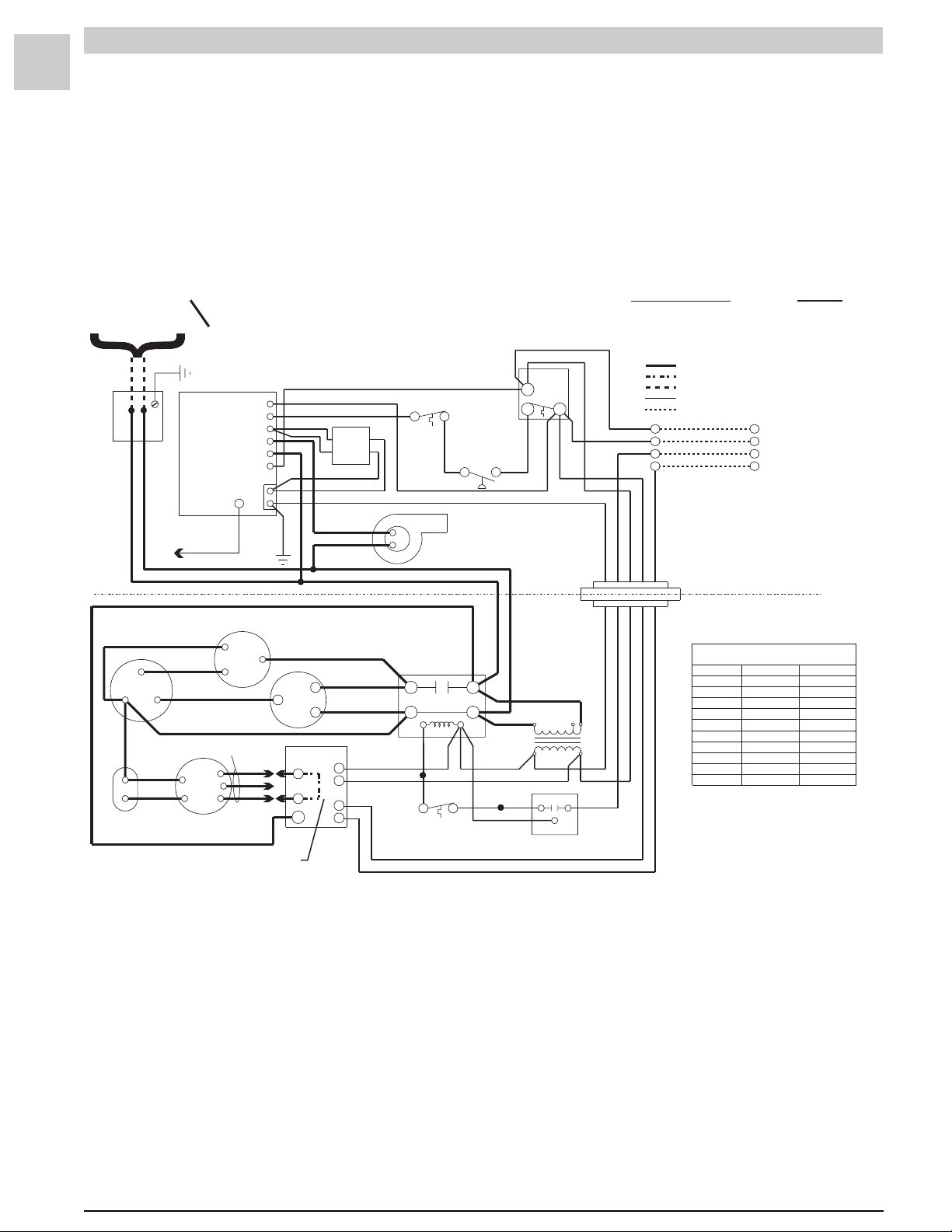
HWC122, 182, 242, 302
(w/Fenwal T(w/Fenwal T
(w/Fenwal T
(w/Fenwal T(w/Fenwal T
208/230-1-60
COPPER CONDUCTORS
POWER SUPPLY
TH
P.S W
V1
IND
BLACK
BLACK
IGNITION
CONTROL
ELECTRODE
CABLE
BLACK
CONDENSER FAN
HERM
RED
BROWN
YEL
VIOLET
BROWN
RED
MOTOR
SEE TABLE
FORWIRING
CAPACITOR-RUN
FAN
COM
CAPACITY BLOWER
BLOWER
24VAC
YELLOW
L1
V2
GND
BLK
BLUE
RED
SEE TABLE
riton 2461D DSI Ignition Contrriton 2461D DSI Ignition Contr
riton 2461D DSI Ignition Contr
riton 2461D DSI Ignition Contrriton 2461D DSI Ignition Contr
CIRCUITS ENERGIZED
OPERATING MODE
ONLY
GREEN
BLACK
S
BLOWER
CONTROL
ORN
ORN
C
H
L1
WHITE
RED
C
R
BLUE
BLUE
BLACK
BLACK
BLACK
RED
BLK
GAS
VALVE
C
R
W
G
PINK
BLUE
MANUAL
RESET
WHITE
PRESSURE
BROWN
COMBUSTION
BLACK
BLACK
T1
CONTACTOR
T2
YEL
BLK
COMP T’STAT
(IF USED)
LIMIT
SWITCH
SWITCH
BLOWER
L1
L2
FORMER
BLUE
RED
BLK
WHITE
GREEN
NO
NC
WHITE
CONNECTOR
BLOCK
BLACK
BLACK
TRANS-
YEL YEL
BLUE
208V
CONTR
LOAD
COM
TIME DELAY
(IF USED)
RED
C
WHITE
BLUE
BLUE
240V
HEATING
COOLING
FAN
LINE VOLTAGE - FACTORY
LINE VOLTAGE - FACTORY (WHEN USED)
LINE VOLTAGE - FIELD
LOWVOLTAGE - FACTORY
LOWVOLTAGE - FIELD
R
W
Y
G
YELLOW
GREEN
WHITE
RED
RED
NOTE:
EVAPORATOR MOTOR
SPEED CONNECTIONS
MODELS
26HWC122
38HWC122
38HWC182
51HWC182
64HWC182
38HWC242
51HWC242
64HWC242
51HWC302
64HWC302
*
ol)ol)
ol)
ol)ol)
CIRCUIT
R-W
R-G-Y
R-G
R
W
THERMOSTAT
Y
G
IF ANY OF THE ORIGINAL
WIRES ARE REPLACED ,
THE SAME SIZE AND TYPE
WIRE MUST BE USED.
HEATING
LOW (RED)
HIGH (BLK)
LOW (RED) LOW (RE D )
MED (BLUE)
HIGH (BLK)
LOW (RED)
MED (BLUE)
HIGH (BLK)
MED (BLUE)
HIGH (BLK)
JUMPER REQUIRED
COOLING
MED (BLUE)
MED (BLUE)
LOW (RED)
LOW (RED)
MED (BLUE)
MED (BLUE)
MED (BLUE)
HIGH (BLK)
HIGH (BLK)
#39007D5
*
*
*
Note: On units that are equipped with a low ambient switch (designated with an “SA” in the model
number), sequence of operation during cooling call is modified when outdoor temperatures fall
below the normal operating range. F or more inf ormation on the low ambient s witch equipped
version of this unit, see the section beginning on page 2-38.
FIGURE 2-3 Connection Diagram
SRM-HW/HWC 2/99
Page 27

Service Reference Manual SEQUENCE OF OPERATIONS
Simplified Sequence - HWC122,182, 242, 302
(w/Fenwal Triton 2461D DSI Ignition Control)
Refer to Figure 2-3
2-17
CALL FOR HEAT
1. A call for heat closes the circuit between wires R
(red) and W (white) on the unit’s thermostat connections.
2. A low voltage (24 volts) signal is sent to the ignition
control, closing a relay which sends line voltage to
the induced draft blower. At the same time, a 24volt signal is also sent to the blow er control board.
This causes the blower control board to begin the
countdown to closing the relay that starts the
circulating air blower .
3. After the induced draft blower creates enough
negative pressure, the pressure s witch closes.
4. When the pressure switch closes, the 24-v olt signal
is sent to the ignition control. This starts a 30second pre-purge countdown, after which a trial for
ignition is made.
5. At the same time that the trial for ignition is made,
the gas valve energizes and gas flo ws to the
burners.
6. With the burners in operation, the trial for ignition
continues for se ven seconds. At the end of this
time, the ignition control stops sparking.
7. Approximately 30 seconds after the burners ignite,
the timer on the blower control board closes a rela y,
sending line voltage to and starting the circulating
air blower.
8. The unit continues to operate as long as there is a
24-volt signal between R and W. When the call f or
heat is satisfied, the 24-volt signal between R and W
discontinues. When W de-energizes, the pow er to
the induced draft blow er and the gas valve is
interrupted. The 24-volt signal to the blo wer control
board is also interrupted, causing the module to
start the countdown to blower “off” (approximately
90 seconds).
9. If at any time during a call for heat the limit switch
opens, the 24-volt signal to the white wire going to
terminal P.SW on the ignition control is interrupted.
This de-energizes the gas valve immediately. The
circulating air blower and the induced draft b lower
continue to run. When the unit cools down enough
for the limit switch to close , the 24-volt signal is
again sent to the P.SW terminal on the ignition
control. With terminal P.SW energized, the ignition
control again makes a trial for ignition and relights
the burners.
CALL FOR COOLING
1. A call for cooling closes the circuit from R to Y and
G.
2. A 24-volt signal is sent to blower control board
terminal G and to the compressor contactor. The
contactor closes, sending line voltage to the compressor and the outdoor condenser fan.
3. With a 24-volt signal at terminal G on the blower
control board, the circulating air blower starts in
cooling speed approximately 15 seconds later (or
immediately - see note below).
4. When the cooling call is completed, G and Y deenergize. The contactor opens immediately, stopping the compressor and the outdoor cooling fan.
When G de-energizes, the timer to turn off the
circulating air blower starts. The circulating air
blower turns off after 90 seconds (see note below).
FAN ON
1. When the thermostat switch is moved to the “FAN
ON” position, the circuit between R and G closes.
2. The 24-volt signal from G goes to the blo wer control
board which starts the timer.
3. Fifteen seconds after terminal G on the blower
control board energizes (or immediately after - see
note below), the circulating air blower starts.
4. When terminal G on the blower control board deenergizes, the timer to turn off the circulating air
blower starts. The circulating air blow er turns off
after 90 seconds (see note below).
Note: Heatcraft blow er control boards ha v e a G “on”
delay of 15 seconds and an “off” dela y of 90
seconds. Tridelta blower control boards have no
“on” time delay and a 60 -130 second “off” delay.
SRM-HW/HWC 2/99
Detailed Sequence follows
Page 28

2-18
SPECIFICATIONS Magic-Pak: HW/HWC
Detailed Sequence - HWC122, 182, 242, 302
(w/Fenwal Triton 2461D DSI Ignition Control)
Refer to Figure 2-3
POWER
Line Voltage
When the service disconnect switch is closed, power is
sent to the unit (unit in standby, no signal from the
thermostat). Power (208 - 230 v olts A/C) is supplied
to both black wires located in the junction block on top
of the unit.
Line voltage will be present at the follo wing locations:
First black wire
1. L-1 on the ignition control
2. L-1 on the contactor
3. L-1 on the blower control board
4. Terminal on the transformer marked 208V or
240V (whichever is being used)
Second black wire
1. Supplies power to the induced draft blower
2. L-2 on the contactor
3. Common terminal on the transformer
4. T-2 on the contactor
5. Red wire on the R terminal of the compressor
6. Red wire to the common terminals on the capaci-
tors
Low Voltage (24 VAC)
With the unit at rest (no call from the thermostat), 24
volts A/C will be found at these points:
1. Red wire exiting the top of the unit
2. Terminal marked 24 VAC on the ignition control
3. Terminal R on the blower control board
CALL FOR HEAT
Line Voltage
The thermostat closes the circuit between R and W.
The following is the sequence of operation f or the line
voltage side of the unit:
1. Terminal TH (24-volt) energizes on the ignition
control, causing the relay in the ignition control
to close. This sends line voltage to the terminal
marked IND, causing the induced draft blower to
start.
2. When W energizes, a 24-v olt signal is also sent to
the W terminal on the blower control board. The
24-volt signal to the blower control board starts
the timer on the board. After 60 seconds , the heat
speed relay on the blower control board closes.
This sends line voltage from the terminal marked
HEAT to the circulating air blower, starting the
blower. The induced draft blower and the circu-
lating air blower continue to operate until the heat
call is satisfied, interrupting the circuit between R
and W. The W terminal de-energizes, causing the
blower rela y to open appro ximately 90 seconds
later. This interrupts the line v oltage to the circulat-
ing air blower and the blow er shuts do wn.
Low Voltage
1. A call for heat closes the circuit in the thermostat
between R and W, sending a 24-volt signal to the
white wire on the unit.
2. The white wire goes to the C terminal on the limit
switch, ignition control terminal TH and terminal
W on the blower control board.
3. When W energizes, the timer starts a countdown to
blower “on”. The blow er starts in approximately 60
seconds.
4. The 24-volt signal sent to terminal TH closes the
relay in the ignition control. This starts the
induced draft blower by energizing terminal IND
on the ignition control.
5. As the induced draft blower comes up to speed
and creates enough negative pressure, the pres-
sure switch closes. The 24-volt signal from the
pressure switch energizes terminal P.SW, causing
the ignition control to start a trial for ignition
(sparking).
6. As the trial for ignition starts, the V1 terminal on the
ignition control energizes. At the same time, a 24volt signal is sent to the gas valve, opening the
valve . The unit contin ues to operate as long as W is
energized.
7. When the call for heat is satisfied, the circuit between R and W is interrupted.
8. With W de-energized, the gas valve closes immediately and the induced draft blower shuts down
sever al seconds later .
9. The blower control board starts a countdown to
blower “off”. Appro ximately 90 seconds later, the
blower shuts do wn.
SRM-HW/HWC 2/99
Page 29

Service Reference Manual SEQUENCE OF OPERATIONS
LIMIT OPENS
If the limit switch opens for an y reason during a call f or
heat, the following happens:
1. If the limit switch senses that the temperature in
the unit is too high, the contacts between terminals
C and NC on the limit switch open and the contacts between C and NO close. This interrupts the
24-volt signal to the pressure switch and also de-
energizes terminal P.SW on the ignition control.
The gas valve closes immediately, as the 24-volt
signal to terminal P.SW is no longer present. The
induced draft blower and the circulating air
blower continue to run. Power to blower control
board terminal W is maintained. The blowers
continue to run until the limit switch closes or the
heat call at the thermostat is satisfied.
2. When the limit switch senses that temperatures in
the unit are normal, the contacts between terminals
C and NO open, the contacts between terminals C
and NC close and operation of the unit returns to
normal.
PRESSURE SWITCH OPENS (BLOCKED FLUE)
1. If blockage of the flue occurs, the negativ e pressure
in the induced draft blower is reduced. At the set
point of the pressure switch, the contacts open.
This interrupts the 24-volt signal to terminal P.SW
on the ignition control. The gas valve closes
immediately, as the relay in the ignition control
opens and interrupts the signal to terminal V2 of the
ignition control.
2. Terminal W on the blower control board stays
energized and the circulating air blower continues to run. If the negativ e pressure is restored, the
pressure switch closes and sends a 24-v olt signal
to the P.SW terminal on the ignition control. The
ignition control makes a trial for ignition again and
operation returns to normal.
2. The reason the rollout switch was tripped must be
determined before corrective action is taken.
3. The signal to terminal P.SW can only be restored if
the rollout switch is reset, which can only be done
manually. The W terminal on the blower control
board remains energized and the circulating air
blower continues to operate. Once the rollout
switch is reset, the operation of the unit returns to
normal.
CALL FOR COOLING
Line Voltage
On a call for cooling, the thermostat closes the circuit
between Y, G and R.
1. With Y energized, the contactor closes. This
sends line voltage to compressor terminal C,
causing the compressor to start. The outdoor fan
also starts, drawing air through the outdoor coil.
2. Terminal G on the blower control board also
energizes at the same time as Y. This starts the
timer on the blower control board. Approximately
15 seconds later (or immediately - see note on page
2-20), the terminal marked COOL energizes. This
sends line voltage to the circulating air blower,
starting the blower.
3. The unit continues cooling as long as both Y and G
are energized. When the cooling call is satisfied,
the circuit between Y, G and R is interrupted. The
contactor immediately opens, interrupting power to
the compressor and the outdoor cooling fan.
4. With the low voltage signal to terminal G on the
blower control board interrupted, the board starts
a countdown to blow er “off”. After appro ximately 90
seconds (see note on page 2-20), the cooling speed
relay opens and the circulating air blower shuts
down.
Low Voltage
2-19
Note: If the P.SW and TH terminals energize at the
same time, the ignition control will not respond.
A pressure switch being stuck closed is an
example of what would cause this to happen.
ROLLOUT SWITCH ACTIVATED
1. If the conditions in the burner compartment cause
the rollout switch to trip, the contacts on the switch
open, interrupting the 24-volt signal going to terminal P.SW on the ignition control. This causes the
ignition control to de-energize terminal V1,
interrupting the 24-volt signal to the gas valve and
immediately closing it.
SRM-HW/HWC 2/99
1. On a call for cooling, the thermostat closes the
circuit between R and terminals G and Y.
2. The 24-volt signal energizes terminal G on the
blower control board, starting the fan “on” timer.
Approximately 15 seconds later (or immediately see note on page 2-20), the relay closes. This
sends line voltage to the COOLING speed terminal
on the blower control board, which starts the
circulating air blower.
3. The signal from Y energizes the contactor, starting
the compressor and the outdoor cooling fan.
4. When the cooling call is satisfied, both G and Y are
de-energized. The contactor opens immediately,
causing the compressor and the outdoor cooling
fan to stop.
Page 30

2-20
SPECIFICATIONS Magic-Pak: HW/HWC
5. The circulating air blower shuts off approximately
90 seconds after G terminal on the blower control
board is de-energized (see note below).
FAN ON
Low Voltage
1. When the switch on the thermostat is mov ed to the
“FAN ON” position, a 24-volt signal is sent to G.
2. With G energized, the blower control board starts
a countdown to fan “on”. After approximately 15
seconds, the fan starts (see note below).
3. The blower control board closes a relay on the
board, sending line voltage to the terminal marked
COOL on the board. This starts the circulating air
blower.
4. When the switch at the thermostat is mov ed to the
“OFF” position, the 24-volt signal to the blower
control board is interrupted. With no signal at the
G terminal, the blower control board starts a
countdown to fan “off”. Appro ximately 90 seconds
later, a relay on the blower control board opens
(see note below). This interrupts the power to and
stops the circulating air blower.
Note: Heatcraft blo wer control boards ha v e a G “on”
delay of 15 seconds and an “off” dela y of 90
seconds. Tridelta blow er control boards have no
“on” time delay and a 60 -130 second “off” delay.
SRM-HW/HWC 2/99
Page 31

Service Reference Manual SEQUENCE OF OPERATIONS
BLANK PAGE
2-21
SRM-HW/HWC 2/99
Page 32

2-22
HW (Heating Only)
(w/Fenwal Triton 2461D DSI Ignition Control)
208/230-1-60
POWER SUPPLY
SPECIFICATIONS Magic-Pak: HW/HWC
CIRCUITS ENERGIZED
COPPER CONDUCTORS
ONLY
IGNITION
CONTROL
BLACK
BLACK
ELECTRODE
CABLE
TH
P.S W
IND
24VAC
GND
V2
V1
L1
WHITE
ORANGE
ORANGE
GREEN
RED
GAS
VALVE
BLUE
BLUE
BLACK
BLACK
BLACK
BLACK
PINK
BROWN
MANUAL
RESET
WHITE
PRESSURE
SWITCH
COMBUSTION
BLOWER
C
NC
WHITE
SWITCH
LIMIT
OPERATING MODE
NO
HEATING
WHITE
RED
YELLOW
BLUE
RED
LINE VOLTAGE - FACTORY
LINE VOLTAGE - FACTORY (WHEN USED)
LINE VOLTAGE - FIELD
LOWVOLTAGE - FACTORY
LOWVOLTAGE - FACTORY (WHEN USED)
LOWVOLTAGE - FIELD
R
W
Y
G
NOTE:
GREEN
WHITE
IF ANY OF THE ORIGINAL
WIRES ARE REPLACED ,
THE SAME SIZE AND TYPE
WIRE MUST BE USED.
CIRCUIT
R-W
R
W
THERMOSTAT
Y
G
CAPACITOR
BLOWER
YELLOW
BROWN
YELLOW
SEE CHART
FORWIRING
BLOWER
MOTOR
BLACK
BLUE
RED
BLUE
BLOWER
CONTROL
C
L1
H
BLOWER
RW
BLACK
WHITE
RED
TRANS-
FORMER
208
240
BLUE
RED
WHITE
GREEN
MOTOR SPEED CONNECTIONS
MODELS
26HW
38HW
51HW
64HW
#39247D2
HEATING
LOW (RED)
HIGH (BLACK)
MED (BLUE)
HIGH (BLACK)
FIGURE 2-4 Connection Diagram
SRM-HW/HWC 2/99
Page 33

Service Reference Manual SEQUENCE OF OPERATIONS
Simplified Sequence - HW (w/Fenwal 2461D Board)
Refer to Figure 2-4
CALL FOR HEAT
1. A call for heat closes the circuit between R and W
on the thermostat. This sends a 24-volt signal to the
white wire on the unit.
2. The 24-volt signal energizes terminal TH on the
ignition control and the W terminal on the blow er
control board.
3. With the TH terminal energized, the ignition control
closes an internal relay. This sends line voltage
from terminal IND to the induced draft blower ,
starting the inducer.
4. After a pre-purge cycle of approximately 30 seconds, the ignition control makes a trial for ignition.
Terminal V1 energizes at this time, opening the gas
valve. The ignition control initiates a spark at the
burner to light the main burners.
5. The trial for ignition lasts sev en seconds, at which
time the ignition control stops sparking. The ignition
control looks at the flame sense to determine if the
main burners have ignited. If flame sense is not
proven, the ignition control goes through another
pre-purge cycle (approximately 30 seconds) and
makes another trial for ignition. It does this three
times. If the three trials for ignition fail, the ignition
control locks out for appro ximately 60 minutes.
After 60 minutes, the ignition control again makes
three trials for ignition. This continues as long as
there is a call for heat from the thermostat.
6. When W energizes , the b lo wer control board starts
a countdown to fan “on”. Approximately 60 seconds
after the thermostat initiates a call for heat, the
circulating air blower starts.
7. The unit continues to operate as long as there is a
call for heat from the thermostat.
8. When the heat call is satisfied, the circuit between R
and W is interrupted. With the white wire deenergized, the ignition control interrupts the 24-volt
signal to the gas valve. This closes the gas valve
immediately and opens the internal relay that deenergizes terminal IND. The induced draft blower
shut downs sev eral seconds later.
9. The W terminal on the blower control board deenergizes. This causes the blower control board to
start a countdown to blower “off”. Approximately 90
seconds later, the circulating air b lower shuts do wn.
This completes the heating cycle.
2-23
SRM-HW/HWC 2/99
Detailed Sequence follows
Page 34

2-24
SPECIFICATIONS Magic-Pak: HW/HWC
Detailed Sequence - HW
(w/Fenwal Triton 2461D Ignition Control)
Refer to Figure 2-4
POWER
Line Voltage
When the service disconnect switch is closed, power is
sent to the unit (unit in standby, no signal from thermo-
stat). Power (208 - 230 v olts A/C) is supplied to the tw o
black wires located in the junction bloc k on top of the
unit.
Line voltage will be present at the follo wing locations:
First black wire
1. L-1 on the ignition control
2. Terminal on the transformer marked 208V or
240V (whichever is being used)
3. Common terminal on the blower capacitor
Second black wire
1. Supplies power to the one side of the induced
draft blower
2. Common terminal on the transformer
3. L terminal on the blower control board
Low Voltage (24 VAC)
With the unit at rest (no call from the thermostat), 24
volts A/C will be found at the f ollo wing points:
1. Red wire exiting the top of the unit
2. Terminal marked NO on the limit switch
2. Terminal marked 24VAC on the ignition control
3. Terminal R on the blower control board
CALL FOR HEAT
Line Voltage
The thermostat closes the circuit between R and W.
The following is the sequence of operation f or the line
voltage side of the unit:
1. Terminal TH on the ignition control energizes,
causing a relay in the ignition control to close.
This sends line voltage to terminal IND on the
ignition control, causing the induced draft
blower to start.
2. When W is energized, a 24-volt signal is also sent
to the W terminal on the blower control board.
Approximately 60 seconds after W terminal ener-
gizes, the timer on the blower control board
closes the heat speed relay on the board. This
sends line voltage to the H terminal on the blower
control board, which starts the circulating air
blower.
3. The induced draft blower and the circulating air
blower continue to operate as long as W is ener-
gized.
4. When W de-energizes, a relay in the ignition
control opens. Terminal IND de-energizes and the
induced draft blower shuts down. Approximately
90 seconds later, the circulating air blower also
shuts down.
Low Voltage
The following is the sequence of operation f or the lo w
voltage side of the unit on a heat call:
1. A call for heat closes the circuit in the thermostat
between R and W, sending a 24-volt signal to the
white wire on the unit.
2. The white wire goes to the C terminal on the limit
switch.
3. The 24-volt signal is sent from the C terminal
(brown wire) on the limit switch to terminal TH on
the ignition control. This causes the ignition
control to close the line voltage relay, starting the
induced draft blower. When the induced draft
blower comes up to speed and creates enough
negative pressure, the pressure switch closes.
4. With the pressure switch closed, the 24-v olt signal
goes to the rollout switch located ov er the b urners.
5. The 24-volt signal from the rollout switch goes to
the terminal marked P.SW on the ignition control,
causing the ignition control to make a trial for
ignition (sparking). Terminal V1 on the ignition
control also energizes at this time, causing the gas
valve to open.
6. At the same time that the C terminal on the limit
switch energizes, a 24-v olt signal is also sent to the
W terminal on the blower control board. This
starts the timer on the blower control board.
Approximately 30 seconds after the main burners
ignite, the blower control board closes a relay;
this sends line voltage to the circulating air
blower, starting the blower .
7. As long as W (white wire) is energized, the unit
continues to operate.
8. When the heat call is satisfied, the circuit between R
and W is interrupted.
SRM-HW/HWC 2/99
Page 35

Service Reference Manual SEQUENCE OF OPERATIONS
9. When W de-energizes, the gas valve immediately
shuts down and the induced draft blower also
stops after several seconds .
10. The blower control board starts a countdown to
blower “off”. Appro ximately 90 seconds later, the
circulating air blower shuts down.
Note: If the P.SW and TH terminals energize at the
same time, the ignition control will not respond.
A pressure switch being stuck closed is an
example of what would cause this to happen.
ROLLOUT SWITCH ACTIVATED
2-25
LIMIT OPENS
If the limit switch opens for an y reason during a call f or
heat, the following happens:
1. If the limit switch senses that the temperature in
the unit is too high, the circuit between terminals C
and NC on the limit switch opens. This closes the
circuit between terminals C and NO on the limit
switch, interrupting the 24-volt signal to the pres-
sure switch and the rollout switch and causing
terminal P.SW on the ignition control to de-
energize. The gas valve immediately closes , as
there is no longer a 24-volt signal at terminal V1 on
the ignition control. With 24 volts still going to the
blower control board and terminal TH on the
ignition control, the circulating air blower and
induced draft blower continue to run.
2. The circulating air blower and the induced draft
blower continue to run as long as there is a call for
heat from the thermostat or the limit switch
remains open.
3. When the limit switch senses that the temperature
in the unit is low enough, the circuit between C and
NO opens and the circuit between C and NC
closes.
4. With the limit switch closed, the unit again makes
a trial for ignition and returns to normal operation.
1. If the conditions in the burner compartment cause
the rollout switch to trip, the contacts on the switch
open. This interrupts the 24-volt signal going to
terminal P.SW on the ignition control, causing
terminal V1 on the ignition control to de-energize.
This interrupts the 24-volt signal to the gas valve
and immediately closes it. Since terminal TH on the
ignition control and W on the blower control
board remain energized, the induced draft
blower and the circulating air blower continue to
run.
2. The 24-volt signal to the ignition control can only
be restored if the rollout switch is manually reset.
3. Once the cause of the rollout switch being tripped
has been determined, the switch can be reset.
4. With the rollout switch reset, terminal P.SW on the
ignition control again energizes. The ignition
control makes a trial for ignition and operation
returns to normal.
PRESSURE SWITCH OPENS (BLOCKED FLUE)
1. If blockage of the flue occurs, the negativ e pressure
in the induced draft blower is reduced. At the set
point of the pressure switch, the contacts open.
This interrupts the 24-volt signal coming from
terminal NC on the limit switch. Terminal P.SW on
the ignition control de-energizes, as does terminal
V1. With loss of the 24-volt signal to the gas valve,
the valve closes immediately.
2. Terminals TH on the ignition control and W on the
blower control board remain energized. The
induced draft blower and the circulating air
blower continue to run.
3. When the pressure switch senses that there is
enough negative pressure within the flue, it will
again close the circuit between the limit switch and
terminal P.SW on the ignition control.
4. The unit makes a trial for ignition and returns to
normal operation.
SRM-HW/HWC 2/99
Page 36

2-26
SPECIFICATIONS Magic-Pak: HW/HWC
HWC122, 182, 242, 302
(w/Fenwal 05-29 Ignition Contr(w/Fenwal 05-29 Ignition Contr
(w/Fenwal 05-29 Ignition Contr
(w/Fenwal 05-29 Ignition Contr(w/Fenwal 05-29 Ignition Contr
208/230-1-60
POWER SUPPLY
BLACK
BLACK
CAPACITOR-RUN
FAN
COM
HERM
RED
YEL
BROWN
CAPACITY
BLOWER
COPPER CONDUCTORS
ONLY
ORANGE
IGNITION
CONTROL
ELECTRODE
CABLE
CONDENSER FAN
VIOLET
BROWN
RED
SEE TABLE
FORWIRING
BLOWER
MOTOR
YELLOW
BLK
BLUE
V1
P.S W
S1
TS
IND
L1
V2
GND
BLACK
S
RED
SEE TABLE
WHITE
GREEN
BLACK
BLOWER
CONTROL
C
H
L1
GAS
VALVE
ORANGE
WHITE
FLAME
SENSOR
RED
BLACK
BLACK
BLACK
C
R
BLK
BLUE
BLUE
MANUAL
RESET
BROWN
T1
BLUE
CONTACTOR
T2
YEL
BLK
COMP T’STAT
(IF USED)
RED
C
R
W
G
WHITE
PRESSURE
SWITCH
COMBUSTION
BLOWER
BLACK
BLACK
L1
L2
BLK
WHITE
GREEN
SWITCH
NO
LIMIT
NC
WHITE
CONNECTOR
BLACK
TRANS-
FORMER
BLUE
RED
YEL YEL
TIME DELAY
(IF USED)
BLACK
ol)ol)
ol)
ol)ol)
C
BLOCK
208V
OPERATING MODE
RED
WHITE
YELLOW
BLUE
BLUE
240V
CIRCUITS ENERGIZED
CIRCUIT
HEATING
COOLING
FAN
LINE VOLTAGE - FACTORY
LINE VOLTAGE - FACTORY (WHEN USED)
LINE VOLTAGE - FIELD
LOWVOLTAGE - FACTORY
LOWVOLTAGE - FIELD
RED
RED
R
W
Y
G
GREEN
WHITE
NOTE:
SPEED CONNECTIONS
MODELS
26HWC122
38HWC122
38HWC182
51HWC182
64HWC182
38HWC242
51HWC242
64HWC242
51HWC302
64HWC302
R
W
Y
G
IF ANY OF THE ORIGINAL
WIRES ARE REPLACED ,
THE SAME SIZE AND TYPE
WIRE MUST BE USED.
EVAPORATOR MOTOR
HEATING
LOW (RED)
HIGH (BLK)
LOW (RED) LOW (RED )
MED (BLUE)
HIGH (BLK)
LOW (RED)
MED (BLUE)
HIGH (BLK)
MED (BLUE)
HIGH (BLK)
JUMPER REQUIRED
*
#39007D4
R-W
R-G-Y
R-G
COOLING
MED (BLUE)
MED (BLUE)
LOW (RED)
LOW (RED)
MED (BLUE)
MED (BLUE)
MED (BLUE)
HIGH (BLK)
HIGH (BLK)
*
*
*
Note: On units that are equipped with a low ambient switch (designated with an “SA” in the model
number), sequence of operation during cooling call is modified when outdoor temperatures fall
below the normal operating range. F or more inf ormation on the low ambient s witch equipped
version of this unit, see the section beginning on page 2-38.
FIGURE 2-5 Connection Diagram
SRM-HW/HWC 2/99
Page 37

Service Reference Manual SEQUENCE OF OPERATIONS
Simplified Sequence - HWC122, 182, 242, 302
(w/Fenwal 05-29 Ignition Control)
Refer to Figure 2-5
2-27
CALL FOR HEAT
1. The thermostat energizes the R-W circuit, sending a
24-volt signal to the W wire at the unit.
2. The 24-volt signal is sent to the ignition control,
closing the combustion blo wer rela y and causing the
combustion blow er to run.
3. The 24-volt signal is also sent to the blow er control
board, starting a 30-second circulation air blower
“on” delay.
4. As the combustion blo wer reaches full speed, it
closes the pressure switch.
5. A 24-volt signal is sent from the pressure switch to
the ignition control. Following a 30-second prepurge delay, this signal energizes the spark terminal.
6. The gas valve solenoid energizes at the same time
as the spark terminal, causing the gas valve to open
and the burners to light.
7. The spark ignitor continues to spark for approximately six seconds or until flame is sensed by the
flame sensor electrode.
8. The unit will operate normally until the R-W circuit is
de-energized by the thermostat, interrupting the 24volt signal to the unit.
9. When the signal is interrupted, the gas valve deenergizes and closes immediately.
10. The combustion blower relay de-energizes se v eral
seconds later, causing the combustion b lo w er to
stop.
11. The blower control board starts a 90-second
circulating air blower “off” delay.
12. Following the 90-second delay, the circulating air
blower stops .
FLAME SENSE
1. After the spark electrode has lit the main burners,
the ignition control waits approximately six seconds
for a flame sense signal.
2. If a flame sense signal is not received after approximately six seconds, the ignition control de-energizes the spark terminal and gas valve.
3. The thermostat R-W circuit sends a 24-volt signal to
the blower control board, starting the circulating air
blower (after a 30-second dela y).
4. The unit initiates three trials for ignition (flame
sense) before system lock out.
CALL FOR COOLING
1. A call for cooling closes the circuit from R to Y and
G.
2. A 24-volt signal is sent to blower control board
terminal G and to the compressor contactor. The
contactor closes, sending line voltage to the compressor and the outdoor condenser fan.
3. With a 24-volt signal at terminal G on the blower
control board, the circulating air blower starts in
cooling speed 15 seconds later (see note below).
4. When the cooling call is completed, G and Y deenergize. The contactor opens immediately, stopping the compressor and the outdoor cooling fan.
When G de-energizes, the timer to turn off the
circulating air blower starts. The blower turns off
after 90 seconds (see note below).
FAN ON
1. When the thermostat switch is moved to the “FAN
ON” position, the circuit between R and G closes.
2. The 24-volt signal from G goes to the blower control
board which starts the timer.
3. Fifteen seconds after terminal G on the blower
control board energizes (or immediately after - see
note below), the circulating air blower starts.
4. When terminal G on the blower control board deenergizes, the timer to turn off the circulating air
blower starts. The blo wer turns off after 90 seconds
(see note below).
Note: Heatcraft blow er control boards ha v e a G “on”
delay of 15 seconds and an “off” dela y of 90
seconds. Tridelta blower control boards have no
“on” time delay and a 60 -130 second “off” delay.
SRM-HW/HWC 2/99
Detailed Sequence follows
Page 38

2-28
SPECIFICATIONS Magic-Pak: HW/HWC
Detailed Sequence - HWC122, 182, 242, 302
(w/Fenwal 05-29 Ignition Control)
Refer to Figure 2-5
POWER
Line Voltage
When the service disconnect switch is closed, power is
sent to the unit (unit in standby, no signal from the
thermostat). Power (208 - 230 v olts A/C) is supplied
to both black wires located in the junction block on top
of the unit.
Line voltage will be present at the follo wing locations:
First black wire
1. L-1 on the ignition module
2. L-1 on the contactor
3. L-1 on the blower control board
4. Terminal on the transformer marked 208V or
240V (whichever is being used)
Second black wire
1. Supplies power to the induced draft blower
2. L-2 on the contactor
3. Common terminal on the transformer
4. T-2 on the contactor
5. Red wire on the R terminal of the compressor
6. Red wire to the common terminals on the capaci-
tors
Low Voltage (24 VAC)
With the unit at rest (no call from the thermostat), 24
volts A/C will be found at these points:
1. Red wire exiting the top of the unit
2. Terminal marked 24VAC on the ignition control
3. Terminal R on the blower control board
CALL FOR HEAT
Line Voltage
The thermostat closes the circuit between R and W.
The following is the sequence of operation f or the line
voltage side of the unit:
1. Terminal TS (24-volt) energizes on the ignition
control, causing a relay in the ignition control to
close. This sends line voltage to the terminal
marked IND, causing the induced draft blower to
start.
2. When W is energized, a 24-volt signal is also sent to
the W terminal on the blower control board. The
24-volt signal starts the timer on the blower con-
trol board. After 60 seconds, the heat speed rela y
on the blower control board closes. This sends
line voltage from the terminal marked HEAT to the
circulating air blower, starting the blower . The
induced draft blower and the circulating air
blower continue to operate until the heat call is
satisfied, interrupting the circuit between R and W.
The W terminal de-energizes, causing the blo wer
relay to open appro ximately 90 seconds later. This
interrupts the line voltage to the circulating air
blower and the blow er shuts do wn.
Low Voltage
1. A call for heat closes the circuit in the thermostat
between R and W, sending a 24-volt signal to the
white wire on the unit.
2. The white wire goes to the C terminal on the limit
switch, ignition control terminal TS and terminal
W on the blower control board.
3. When W energizes, the timer starts a countdown to
circulating air blower “on”. The blower starts in
approximately 60 seconds.
4. The 24-volt signal sent to the TS terminal closes a
relay in the ignition control. This starts the
induced draft blower by energizing terminal IND
on the ignition control.
5. As the induced draft blower comes up to speed
and creates enough negative pressure, the pres-
sure switch closes. The 24-volt signal is sent from
the pressure switch to one side of the Normally
Closed manual reset rollout switch. If the
rollout switch is closed, the 24-volt signal is
passed through the switch to the P.SW terminal on
the ignition control. This initiates a 30-second prepurge period.
6. After the 30-second pre-purge period, a trial for
ignition starts by energizing the spark terminal and
the V1 terminal simultaneously. The 24-volt signal
from V1 energizes the gas valve solenoid, causing
it to open. These actions cause the burners to light.
7. After the burners are lit, a flame sense is picked up
by the flame sense rod located at the opposite
end of the burner rack from the spark electrodes.
The flame sense signal is sent to the S1 terminal of
the ignition control. The unit contin ues to oper ate
as long as W is energized.
8. When the call for heat is satisfied, the circuit between R and W is interrupted, de-energizing W.
SRM-HW/HWC 2/99
Page 39

Service Reference Manual SEQUENCE OF OPERATIONS
9. With W de-energized, the gas valve closes immediately and the induced draft blower stops sev e ral
seconds later.
10. The blower control board starts a 90-second
circulating air blower “off” dela y. Approximately
90 seconds later, the blo w er stops.
FLAME SENSE
1. During a call for heat, the spark terminal is energized and the gas valve is opened to light the
burners.
2. The ignition control energizes the spark terminal
and the gas valve for approximately six seconds . If
a flame is not sensed in this time period, the igni-
tion control de-energizes the spark terminal and
the gas valve. This causes the gas valve to close
and the burners to shut off.
3. Since the 24-volt signal has been sent to the
blower control board, the circulating air blower
times “on” in appro ximately 60 seconds .
4. The induced draft blower continues to run for
approximately 30 seconds, then another trial for
ignition begins.
5. The ignition control runs three trials for ignition. If
a flame is not sensed during these three trials, the
ignition control will lockout.
6. The circulating air blower continues to run until
the R-W circuit at the thermostat is interrupted.
7. The ignition control remains in lockout until 24-v olt
power to the ignition control is reset.
LIMIT OPENS
If the limit switch opens for an y reason during a call f or
heat, the following happens:
PRESSURE SWITCH OPENS (BLOCKED FLUE)
1. If blockage of the flue occurs, negativ e pressure in
the induced draft blower is reduced. At the set
point of the pressure switch, the contacts open.
This interrupts the 24-volt signal to terminal P.SW
on the ignition control. The gas valve closes
immediately, as a relay in the ignition control
opens and interrupts the signal to terminal V2 of the
ignition control.
2. Terminal W on the blower control board stays
energized and the circulating air blower continues to run. If negative pressure is restored, the
pressure switch closes and sends a 24-volt signal
to the P.SW terminal on the ignition control. The
ignition control makes a trial for ignition again and
the operation returns to normal.
ROLLOUT SWITCH ACTIVATED
1. If conditions in the burner compartment cause the
rollout switch to trip, the contacts on the switch
open, interrupting the 24-volt signal going to terminal P.SW on the ignition control. This causes the
ignition control to de-energize terminal V1,
interrupting the 24-volt signal to the gas valve and
immediately closing it.
2. The reason the rollout switch was tripped must be
determined before any corrective action is taken.
3. The signal to terminal P.SW can only be restored if
the rollout switch is reset, which can only be done
manually. The W terminal on the blower control
board remains energized and the circulating air
blower continues to operate. Once the rollout
switch is reset, the operation of the unit returns to
normal.
2-29
1. If the limit switch senses that the temperature in
the unit is too high, the contacts between terminals
C and NC on the limit switch open and the contacts between C and NO close. This interrupts the
24-volt signal to the pressure switch and also de-
energizes terminal P.SW on the ignition control.
The gas valve closes immediately, as the 24-volt
signal to terminal P.SW is no longer present. The
induced draft blower and the circulating air
blower continue to run. Power to blower control
board terminal W is maintained. The b lo wer
continues to run until the limit switch closes or the
heat call at the thermostat is satisfied.
2. When the limit switch senses that the temperatures in the unit are normal, the contacts between
terminals C and NO open, the contacts between
terminals C and NC close and the operation of the
unit returns to normal.
SRM-HW/HWC 2/99
CALL FOR COOLING
Line Voltage
On a call for cooling, the thermostat closes the circuit
between Y, G and R.
1. With Y energized, the contactor closes. This
sends line voltage to compressor terminal C,
causing the compressor to start. The outdoor fan
also starts, drawing air through the outdoor coil.
2. Terminal G on the blower control board also
energizes at same time as Y. This starts the timer
on the blower control board. Approximately 15
seconds later (or immediately - see note on page 2-
30), the terminal marked COOL energizes. This
sends line voltage to the circulating air blower,
starting the blower.
Page 40

2-30
SPECIFICATIONS Magic-Pak: HW/HWC
3. The unit continues cooling as long as both Y and G
are energized. When the cooling call is satisfied,
the circuit between Y, G and R is interrupted. The
contactor immediately opens, interrupting power to
the compressor and the outdoor cooling fan.
4. With the low voltage signal to terminal G on the
blower control board interrupted, the board starts
a countdown to blow er “off”. After appro ximately 90
seconds, the cooling speed relay opens and the
circulating air blower shuts down (see note at the
end of this section).
Low Voltage
1. On a call for cooling, the thermostat closes the
circuit between R and terminals G and Y.
2. The 24-volt signal energizes terminal G on the
blower control board, starting the fan “on” timer.
After approximately 15 seconds, the rela y closes
(see note at the end of this section). This sends line
voltage to the COOLING speed terminal on the
board, which starts the circulating air blower.
3. The signal from Y energizes the contactor, starting
the compressor and the outdoor cooling fan.
4. When the cooling call is satisfied, both G and Y deenergize. The contactor opens immediately,
causing the compressor and the outdoor cooling
fan to stop.
5. The circulating air blower stops approximately 90
seconds after the G terminal on the blower control
board de-energizes (see note at the end of this
section).
Note: Heatcraft blo w er control boards have a G “on”
delay of 15 seconds and an “off” dela y of 90
seconds. Tridelta blower control boards have no
“on” time dela y and a 60 -130 second “off” dela y.
FAN ON
Low Voltage
1. When the switch on the thermostat is mov ed to the
“FAN ON” position, a 24-volt signal is sent to the G
terminal on the blower control board.
2. With G energized, the blower control board starts
a countdown to fan “on”. Approximately 15 seconds
later (or immediately - see note at the end of this
section), the fan starts.
3. The blower control board closes a relay on the
board, sending line voltage to the terminal on the
board marked COOL. This starts the circulating
air blower.
4. When the switch at the thermostat is mov ed to the
“OFF” position, the 24-volt signal to the blower
control board is interrupted. With no signal at the
G terminal, the blower control board starts a
countdown to fan “off”. Appro ximately 90 seconds
later, a relay on the blower control board opens
(see note at the end of this section). This interrupts
the power to and stops the circulating air blower.
SRM-HW/HWC 2/99
Page 41

Service Reference Manual SEQUENCE OF OPERATIONS
BLANK PAGE
2-31
SRM-HW/HWC 2/99
Page 42

SPECIFICATIONS Magic-Pak: HW/HWC
2-32
HW (Heating Only)
(w/Fenwal 05-29 Ignition Control)
208/230-1-60
POWER SUPPLY
CIRCUITS ENERGIZED
OPERATING MODE
COPPER CONDUCTORS
ONLY
GAS
ORANGE
VALVE
ORANGE
V1
P.S W
S1
TS
BLACK
BLACK
IGNITION
CONTROL
ELECTRODE
IND
L1
V2
GND
CABLE
WHITE
GREEN
WHITE
SENSOR
RED
FLAME
BLACK
BLACK
BLACK
BLACK
BLUE
BLUE
BROWN
MANUAL
RESET
WHITE
COMBUSTION
BLOWER
LIMIT
SWITCH
PRESSURE
SWITCH
NO
C
NC
WHITE
RED
YELLOW
BLUE
HEATING
LINE VOLTAGE - FACTORY
LINE VOLTAGE - FACTOR Y (WHEN USED)
LINE VOLTAGE - FIELD
WHITE
RED
LOWVOLTAGE - FACTORY
LOWVOLTAGE - FACTORY (WHEN USED)
LOWVOLTAGE - FIELD
R
W
Y
G
WHITE
NOTE:
GREEN
R
W
Y
G
IF ANY OF THE ORIGINAL
WIRES ARE REPLACED ,
THE SAME SIZE AND TYPE
WIRE MUST BE USED.
CIRCUIT
R-W
THERMOSTAT
CAPACITOR
BLOWER
YELLOW
BROWN
YELLOW
BLOWER
MOTOR
SEE CHART
FORWIRING
BLACK
BLUE
RED
BLUE
BLOWER
CONTROL
C
L1
H
BLOWER
RW
BLACK
WHITE
RED
TRANS-
FORMER
208
240
BLUE
RED
WHITE
GREEN
MOTOR SPEED CONNECTIONS
MODELS
26HW
38HW
51HW
64HW
#39247D1
HEATING
LOW (RED)
HIGH (BLACK)
MED (BLUE)
HIGH (BLACK)
FIGURE 2-6 Connection Diagram
SRM-HW/HWC 2/99
Page 43

Service Reference Manual SEQUENCE OF OPERATIONS
Simplified Sequence - HW (w/Fenwal 05-29 Board)
Refer to Figure 2-6
CALL FOR HEAT
1. The indoor thermostat calls for heat by energizing
the R-W circuit.
2. This sends a 24-volt signal to the ignition control,
causing the induced draft blower to run.
3. A 24-volt signal is also sent to the blo wer control
board at this time, starting a 60-second circulating
air blower “on” delay. The circulating air blower
starts 60 seconds after the initial call for heat.
4. The induced draft blow er causes the pressure
switch to close which starts a 30-second pre-purge.
After the pre-purge period, the burners ignite.
5. The unit operates in the heating mode until the
indoor thermostat setting is reached and the R-W
circuit is interrupted.
6. When the R-W circuit is interrupted, the 24-volt
signal to the ignition control and the signal to the
blower control board are interrupted.
7. The induced draft blower stops within se v eral
seconds and a 90-second circulating air blower “off”
delay starts. F o llowing the delay period, the circulating air blower shuts off .
2-33
SRM-HW/HWC 2/99
Detailed Sequence follows
Page 44

2-34
SPECIFICATIONS Magic-Pak: HW/HWC
Detailed Sequence - HW
(w/Fenwal 05-29 Ignition Control)
Refer to Figure 2-6
POWER
Line Voltage
When the service disconnect switch is closed, power is
sent to the unit (unit in standby, no signal from the
thermostat). Power (208 - 230 v olts A/C) is supplied
to both black wires located in the junction block on top
of the unit.
Line voltage will be present at the follo wing locations:
First black wire
1. L-1 on the ignition module
2. Terminal on the transformer marked 208V or
240V (whichever is being used)
3. Circulating air blower capacitor terminal
Second black wire
1. Supplies power to the induced draft blower
2. Common terminal on the transformer
3. Terminal L-1 on the blower control board
Low Voltage (24 VAC)
With the unit at rest (no call from the thermostat), 24
volts A/C will be found at these points:
1. Red wire exiting the top of the unit
2. Terminal R on the blower control board
3. Terminal NO on the limit switch
4. Terminal on the transformer marked 24V
CALL FOR HEAT
Line Voltage
The thermostat closes the circuit between R and W.
The following is the sequence of operation f or the line
voltage side of the unit:
1. Terminal TS (24-volt) energizes on the ignition
control, causing a relay in the ignition control to
close. This sends line voltage to the terminal
marked IND, causing the induced draft blower to
start.
2. When W is energized, a 24-volt signal is also sent
to the W terminal on the blower control board.
The 24-volt signal starts the timer on the blower
control board. After 60 seconds, the relay on the
blower control board closes. This sends line
voltage from the terminal marked L-1 to the terminal
marked H on the blower control board, starting
the circulating air blower. The induced draft
blower and the circulating air blower continue to
operate until the heat call is satisfied, interrupting
the circuit between R and W. The ignition control
de-energizes the induced draft blower rela y,
interrupting L-1 power to the induced draft blower.
The induced draft blower stops several seconds
later. The W terminal on the blower control board
de-energizes, starting a 90-second blower “off”
delay. This interrupts the line v oltage to the circu-
lating air blower and after 90 seconds, the blo w er
shuts down.
Low Voltage
1. A call for heat closes the circuit in the thermostat
between R and W, sending a 24-volt signal to the
white wire on the unit.
2. The white wire goes to the C terminal on the limit
switch, ignition control terminal TS and terminal
W on the blower control board.
3. When W energizes, the timer starts a countdown to
circulating air blower “on”. The blower starts in
approximately 60 seconds.
4. The 24-volt signal sent to the TS terminal closes a
relay in the ignition control. This starts the
induced draft blower by energizing terminal IND
on the ignition control.
5. As the induced draft blower comes up to speed
and creates enough negative pressure, the pres-
sure switch closes. The 24-volt signal is sent from
the pressure switch to one side of the Normally
Closed manual reset rollout switch. If the
rollout switch is closed, the 24-volt signal is
passed through the switch to the P.SW terminal on
the ignition control. This initiates a 30-second
pre-purge period.
6. After the 30-second pre-purge period, a trial for
ignition starts by energizing the spark terminal and
the V1 terminal simultaneously. The 24-volt signal
from V1 energizes the gas valve solenoid, causing
it to open. These actions cause the burners to light.
7. After the burners are lit, a flame sense is picked up
by the flame sense rod located at the opposite
end of the burner rack from the spark electrodes.
The flame sense signal is sent to the S1 terminal of
the ignition control. The unit contin ues to oper ate
as long as W is energized.
SRM-HW/HWC 2/99
Page 45

Service Reference Manual SEQUENCE OF OPERATIONS
8. When the call for heat is satisfied, the circuit between R and W is interrupted, de-energizing W.
9. With W de-energized, the gas valve closes immediately and the induced draft blower stops sev e ral
seconds later.
10. The blower control board starts a 90-second
blower “off” delay. Appro ximately 90 seconds later,
the blower stops .
FLAME SENSE
1. During a call for heat, the spark terminal is energized and the gas valve is opened to light the
burners.
2. The ignition control energizes the spark terminal
and the gas valve for approximately six seconds . If
a flame is not sensed in this time period, the igni-
tion control de-energizes the spark terminal and
the gas valve. This causes the gas valve to close
and the burners to shut off.
3. Since the 24-volt signal has been sent to the
blower control board, the circulating air blower
times on in approximately 60 seconds.
4. The induced draft blower continues to run for
approximately 30 seconds, then another trial for
ignition begins.
5. The ignition control runs three trials for ignition. If
a flame is not sensed during these three trials, the
ignition control will lockout.
6. The circulating air blower continues to run until
the R-W circuit at the thermostat is interrupted.
7. The ignition control remains in lockout until 24-v olt
power to the ignition control is reset.
LIMIT OPENS
PRESSURE SWITCH OPENS (BLOCKED FLUE)
1. If blockage of the flue occurs, negativ e pressure in
the induced draft blower is reduced. At the set
point of the pressure switch, the contacts open.
This interrupts the 24-volt signal to terminal P.SW
on the ignition control. The gas valve closes
immediately, as a relay in the ignition control
opens and interrupts the signal to terminal V2 of the
ignition control.
2. Terminal W on the blower control board stays
energized and the circulating air blower continues to run. If negative pressure is restored, the
pressure switch closes and sends a 24-volt signal
to the P.SW terminal on the ignition control. The
ignition control makes a trial for ignition again and
the operation returns to normal.
ROLLOUT SWITCH ACTIVATED
1. If conditions in the burner compartment cause the
rollout switch to trip, the contacts on the switch
open, interrupting the 24-volt signal going to terminal P.SW on the ignition control. This causes the
ignition control to de-energize terminal V1,
interrupting the 24-volt signal to the gas valve and
immediately closing it.
2. The reason the rollout switch was tripped must be
determined before any corrective action is taken.
3. The signal to terminal P.SW can only be restored if
the rollout switch is reset, which can only be done
manually. The W terminal on the blower control
board remains energized and the circulating air
blower continues to operate. Once the rollout
switch is reset, the operation of the unit returns to
normal.
2-35
If the limit switch opens for an y reason during a call f or
heat, the following happens:
1. If the limit switch senses that the temperature in
the unit is too high, the contacts between terminals
C and NC on the limit switch open and the contacts between C and NO close. This interrupts the
24-volt signal to the pressure switch and also de-
energizes terminal P.SW on the ignition control.
The gas valve closes immediately, as the 24-volt
signal to terminal P.SW is no longer present. The
induced draft blower and the circulating air
blower continue to run. Power to blower control
board terminal W is maintained. The b lo wer
continues to run until the limit switch closes or the
heat call at the thermostat is satisfied.
2. When the limit switch senses that the temperatures in the unit are normal, the contacts between
terminals C and NO open, the contacts between
terminals C and NC close and the operation of the
unit returns to normal.
SRM-HW/HWC 2/99
Page 46

2-36
SPECIFICATIONS Magic-Pak: HW/HWC
HWC123, 183, 243, 303 Low Ambient
(w/United Technologies 1097 Spark Ignition System)
CONNECTION DIAGRAMCONNECTION DIAGRAM
CIRCUITS ENERGIZED
208/230-1-60
POWER SUPPLY
}
BLACK
BLACK
COPPER CONDUCTORS
BLACK
ONLY
BLACK
COMBUSTION
BLACK
BLOWER
VIOLET
PRESSURE
SWITCH
VIOLET
AUTO RESET
LIMIT SWITCH
GAS
VALVE
ORANGE
GREEN
RED
RED
BLUE
ORANGE
CNB
WHITE
RGWCY
MANUAL RESET
LIMIT SWITCH
L1
COOL
BLACK
(WHEN USED)(WHEN USED)
IGNITION
CONTROL
4
5
6
2
3
1
YELLOW
RED
BLACK
HEAT
UNUSED
GND
ORANGE
RED
BLACK
BLUE
WHITE
24VAC
GREEN
ELECTRODE
FLAME ROD
OPERATING MODE CIRCUITOPERATING MODE CIRCUIT
HEATING R-W
COOLING R-G-Y
FAN R-G
LINE VOLTAGE-FA CTORY
LINE VOLTAGE-FACTORYWHEN USED
LINE VOLTAGE-FIELD
LOWVOLTAGE-FACTOR Y
LOWVOLTAGE-FIELD
R
G
Y
W
R
G
Y
W
NOTE:
IF ANY OF THE ORIGINAL
WIRES ARE REPLACED,THE
BLUE
YELLOW
RED
SAME SIZE AND TYPE WIRESAME SIZE AND TYPE WIRE
MUST BE USED.
THERMOST AT
}
YELLOW
FAN CONTROL
BLACK
C
COMP
R
H
M
L
BLOCK
CAPACITOR-RUN
FAN
COM
HERM
RED
YELLOWYELLOW
BROWN
CAPACITOR
BLOWER
CONDENSER FAN
VIOLET
BROWN
YELLOW
RED
BLOWER
MOTOR
FAN RELAY
SEE
CHART
FORWIRING
BLACK
BLUE
RED
S
TERMINAL
FIGURE 2-7 Connection Diagram
TRANSFORMER
BLACK
RED
BLUE
RED
BLACK
208 V
CONTACTOR
T1
T2
BLK
240 V
BLK
L1
L2
BLUE
YELLOW
CONNECTOR
BLOCK
EVAP. MOTOR SPEED CONNECTIONS
26HWC123SA
38HWC123SA38HWC123SA
38HWC183SA
51HWC183SA51HWC183SA
64HWC183SA64HWC183SA
38HWC243SA
51HWC243SA
64HWC243SA
51HWC303SA
64HWC303SA
JUMPER REQUIRED
*
HEATINGMODELS
MED (BLUE)LOW (RED)
MED (BLUE)HIGH(BLACK)
LOW (RED)LOW (RED)
LOW (RED)MED (BLUE)
LOW (RED)HIGH(BLACK)
MED (BLUE)LOW (RED)
MED (BLUE)MED (BLUE)
MED (BLUE)HIGH(BLACK)
HIGH(BLACK)MED (BLUE)
HIGH(BLACK)HIGH(BLACK)
#45005-2
COOLING
*
*
*
DIAGNOSTICS
The following blower/ignition control board
LED codes will indic a te n o rmal or abnormal
operations:
SLOW FLASH Normal Operation, No
FAS T F L A SH Normal Operation,Call for
2 FLASH System Lockout - Failed to
3 FLASH Pressure Switch Open or
4 FLASH High Limit or Rollout
5 FLASH Flame Sensed and Gas
STEADY Internal Failure
Call for Heat
Heat
Detect or Sustain Flame
Closed
Switch Open
Valve Not Energized
(Micro-controlle r Failure;
Self-check)
SRM-HW/HWC 2/99
Page 47

Service Reference Manual SEQUENCE OF OPERATIONS
HWC123,183, 243, 303
Low Ambient Model
Refer to Figure 2-7
The low ambient switch is designed to allo w the operation of the air conditioning unit below the normal operating range. On units equipped with this s witch, sequence
of operation during a cooling call is modified when
outdoor temperatures fall below the normal operating
range.
The switch will interrupt the operation of the outdoor
cooling fan when the temperature of the liquid line
coming in from the outdoor coil falls below 55° F. When
the temperature of the liquid line rises to 95° F, the
switch will close and the outdoor fan will resume oper ation.
The low ambient switch does not aff ect an y other facet
of the operation of the unit.
2-37
To see simplified and detailed sequences of operation
for the HWC123, 183, 243, 303 models, ref er to pages
2-5 to 2-9.
SRM-HW/HWC 2/99
Page 48

2-38
SPECIFICATIONS Magic-Pak: HW/HWC
HWC122, 182, 242, 302 Low Ambient
CIRCUITS ENERGIZED
208/230-1-60
POWER SUPPLY
BLACK
BLACK
ELECTRODE
FAN
RED
VIOLET
BROWN
HERM
YEL
BRN
CAPACITOR-RUN
COM
CAPACITOR
BLOWER
COPPER CONDUCTORS
ONLY
IGNITION
CONTROL
CABLE
CONDENSER FAN
YELLOW
RED
FORWIRING
BLOWER
MOTOR
P.S W
24VAC
GND
BLACK
SEE TABLE
BLK
BLU
RED
TH
VI
IND
L1
V2
SEE TABLE
ORN
ORN
GREEN
S
C
H
L1
WHITE
RED
C
R
BLACK
GAS
VALVE
BLUE
BLUE
BLACK
BLACK
BLACK
RED
C
R
W
G
PINK
BLUE
MANUAL
RESET
BROWN
BLACK
BLACK
CONTACTOR
T1
T2
WHITE
PRESSURE
SWITCH
COMBUSTION
BLOWER
L1
L2
YELLOW
WHITE
GREEN
BLACK
TRANS-
FORMER
BLUE
RED
YELLOW
NO
NC
LIMIT
SWITCH
WHITE
BLACK
BLACK
BLACK
24V
C
208V
240V
RED
WHITE
YELLOW
BLUE
BLUE
OPERATING MODE
HEATING
COOLING
FAN
LINE VOLTAGE - FACTORY
LINE VOLTAGE - FACTORY (WHEN USED)
LINE VOLTAGE - FIELD
LOWVOLTAGE - FACTORY
LOWVOLTAGE - FIELD
R
W
Y
G
NOTE:
IF ANY OF THE ORIGINAL
RED
RED
WHITE
GREEN
WIRES ARE REPLACED ,
THE SAME SIZE AND TYPE
WIRE MUST BE USED.
CONNECTOR
BLOCK
FAN
CONTROL
BLACK
MODELS
26HWC122
38HWC122
38HWC182
51HWC182
64HWC182
38HWC242
51HWC242
64HWC242
51HWC302
64HWC302
BLACK
EVAPORATOR MOTOR
SPEED CONNECTIONS
JUMPER REQUIRED
*
CIRCUIT
R-W
R-G-Y
R-G
R
W
THERMOSTAT
Y
G
FAN
RELAY
13
HEATING
LOW (RED)
HIGH (BLK)
LOW (RED) LOW (RED)
MED (BLUE)
HIGH (BLK)
LOW (RED)
MED (BLUE)
HIGH (BLK)
MED (BLUE)
HIGH (BLK)
COOLING
MED (BLUE)
MED (BLUE)
LOW (RED)
LOW (RED)
MED (BLUE)
MED (BLUE)
MED (BLUE)
HIGH (BLK)
HIGH (BLK)
*
*
*
FIGURE 2-8 Connection Diagram
#44358-2
SRM-HW/HWC 2/99
Page 49

Service Reference Manual SEQUENCE OF OPERATIONS
HWC122,182, 242, 302
Low Ambient Model
Refer to Figure 2-8
The low ambient switch is designed to allo w the operation of the air conditioning unit below the normal operating range. On units equipped with this s witch, sequence
of operation during a cooling call is modified when
outdoor temperatures fall below the normal operating
range.
The switch will interrupt the operation of the outdoor
cooling fan when the temperature of the liquid line
coming in from the outdoor coil falls below 55° F. When
the temperature of the liquid line rises to 95° F, the
switch will close and the outdoor fan will resume oper ation.
The low ambient switch does not aff ect an y other facet
of the operation of the unit.
2-39
To see simplified and detailed sequences of operation
for the HWC122, 182, 242, 302 models equipped with
the Fenwal Triton 2461D DSI Ignition Control, refer to
pages 2-17 to 2-20.
To see simplified and detailed sequences of operation
for the HWC122, 182, 242, 302 models equipped with
the Fenwal 05-29 Ignition Control, ref er to pages 2-27 to
2-30.
SRM-HW/HWC 2/99
Page 50

Service Reference Manual UNIT TEAR DOWN
Section 3 - Unit Tear Down
Heating Section
Heat Exchanger Removal ............................ 3-2
Induced Draft Blower Removal ..................... 3-2
Cooling Section
Chassis Removal ........................................ 3-4
Evaporator Blower Assembly Removal .......... 3-6
3-1
SRM-HW/HWC 8/99
Page 51

3-2
UNIT TEAR DOWN Magic-Pak: HW/HWC
UNIT TEAR DOWN
HWC units are comprised of two major sections.
The heating section is located in the top half of the unit. It contains the
heat exchanger and the majority of the components associated with the
heating function: controls , b urners, switches , etc.... The total heating
section is not removab le as a complete unit. The heat e xchanger may be
removed separately f or service (see below).
The cooling section is located in the lower half of the unit. It contains
the compressor, coils and motors that mak e up the refrigeration system.
The cooling section is referred to as the “chassis” of the cooling system.
The chassis is removab le as a complete unit. Remov al of the chassis
allows service to be performed away from the job site, thus allo wing a
spare chassis to be installed to reduce downtime at a residence. Bench
tests may be perf ormed on chassis. See the Perf ormance Test section
beginning on page 9-11 for chassis performance data of both bench
tested and installed units.
Heating Section
Heat Exchanger Removal:
The heat exchanger may be remo v ed from the unit through the front side .
Refer to the f ollowing directions and Figure 3-1.
To remove the heat exchanger:
1. Disconnect all power to the unit.
2. Shut off and disconnect the gas supply.
3. Open the burner access panel.
4. Remove the burner tra y and the gas v alv e .
5. Remove the front heat section panel.
6. Remove the vestib ule panel.
7. Remove the heat e xchanger .
Induced Draft (Combustion) Blower Removal:
Refer to the f ollowing directions and Figure 3-1.
To remove the induced draft blower:
1. Disconnect all power to the unit.
2. Shut off and disconnect the gas supply.
3. Remove the plate mounting scre ws.
4. Slide the induced draft blower out.
SRM-HW/HWC 8/99
Page 52

Service Reference Manual UNIT TEAR DOWN
PLATE MOUNTING
SCREWS
INDUCED DRAFT BLOWER/
COMBUSTION BLOWER
HEAT EXCHANGER
FRONT HEAT
SECTION PANEL
GAS VALVE
HEATING SECTION
VESTIBULE PANEL
3-3
CONTROL SECTION
COOLING SECTION
BURNER ACCESS PANEL
BURNER TRAY
FILTER ACCESS DOOR
Figure 3-1
SRM-HW/HWC 8/99
Page 53

3-4
FILLER PANEL
HOLD DOWN
SCREWS
L1/L2 WIRES
6-PIN
LOW VOLTAGE
MOLEX PLUG
RIGHT SIDE
CHASSIS SCREW
UNIT TEAR DOWN Magic-Pak: HW/HWC
Cooling Section
Chassis Removal:
The cooling chassis may be remov ed from behind the filter access door.
Refer to the follo wing directions and Figures 3-1 to 3-4.
To remove the cooling chassis:
1. Disconnect all power to the unit.
2. Shut off and disconnect the gas supply.
3. Remove the filter access door (Figure 3-1).
4. Disconnect L1 and L2 from the compressor contactor (Figure 3-2).
5. Disconnect the 6-pin low voltage mole x plug (Figure 3-2).
6. Remove the filler panel by removing the four hold down screws
(Figure 3-2).
7. Remove the right side chassis screw (Figure 3-2).
8. Remove the permagum seal on the base rails of the chassis (Figure
3-4).
9. Disconnect the drain tube from the evapor ator drain pan (Figure 3-3).
10. Remove the chassis from the front of the unit, pulling it toward
yourself (Figure 3-4).
Figure 3-2
SRM-HW/HWC 8/99
Page 54

Service Reference Manual UNIT TEAR DOWN
EVAPORATOR BLOWER MOTOR
Figure 3-3
EVAPORATOR
3-5
EVAPORATOR DRAIN
TUBE CONNECTION
EVAPORATOR DRAIN PAN
COMPRESSOR
CHASSIS SHOWN
PARTIALLY REMOVED
LOW VOLTAGE
MOLEX PLUG
SRM-HW/HWC 8/99
Figure 3-4
EVAPORATOR DRAIN
TUBE CONNECTION
DRAIN HOSE (NOT PICTURED)
ARMSTRONG P/N 03613A001
17" LONG
.63" (5/8") I.D.
.13" WALL THICKNESS
PERMAGUM SEAL
Page 55

3-6
UNIT TEAR DOWN Magic-Pak: HW/HWC
Evaporator Blower Assembly Removal:
The evapor ator blo wer assemb ly is remo v able as one complete section.
To remove the assembly, the chassis must be removed first (see page 3-
4). Ref er to the f ollo wing directions and Figure 3-5.
To remove the evaporator blo wer assemb ly:
1. Remove the f our mounting screws from the b lo wer assemb ly.
2. Remove the f our control panel scre ws.
3. Slide control panel toward yourself about 1".
4. Disconnect the electrical wiring to the motor.
5. Pull blower assembly up and out from chassis .
MOUNTING SCREWS
EVAPORATOR BLOWER
ASSEMBLY
CONTROL PANEL
SCREWS
Figure 3-5
R
O
T
A
T
I
O
N
CHASSIS BASE
PERMAGUM SEAL
(BETWEEN BASE RAIL AND CHASSIS BASE)
SRM-HW/HWC 8/99
Page 56

Service Reference Manual COMPONENT LOCATION ILLUSTRATIONS
Section 4 - Component Location
Illustrations
HW/HWC(3) Unit ................................. 4-2
HW/HWC(2) Unit ................................. 4-3
HW/HWC - Panels................................ 4-4
HW/HWC - Exterior Louver/Grill Panel .. 4-5
HWC Chassis Assembly ........................ 4-6
4-1
HWC Chassis Assembly - Top View ......... 4-7
HWC Chassis Assembly Circulating Air Blower Partially Removed 4-8
SRM-HW/HWC 2/99
Page 57

COMPONENT LOCATION ILLUSTRATIONS Magic-Pak: HW/HWC
4-2
HW/HWC123,183,243,303
IGNITION/BLOWER CONTROL BOARD (*24)
UNITED TECHNOLOGIES 1097-83-400A/1097-400-I
ARMSTRONG P/N 44990-001
HEATING SECTION
(DSI)*
MAIN LIMIT SWITCH (*52)
ARMSTRONG P/N 40154B007
GAS VALVE
HONEYWELL VR8105M8202
ARMSTRONG P/N 44987-001
CONTROL SECTION
COOLING SECTION
* SEE COMPONENT SECTION FOR FURTHER
DETAIL OF IGNITION/BLOWER CONTROL
PRESSURE SWITCH (*57)
BURNER TRAY
FIGURE 4-1
The numbers in parentheses in the drawing abov e refer to the section number each part is assigned. These numbers are provided here to aid in locating the parts in the Parts List section found beginning on page 8-1.
SRM-HW/HWC 2/99
Page 58

Service Reference Manual COMPONENT LOCATION ILLUSTRATIONS
HW/HWC122, 182, 242, 302
FENWAL IGNITION CONTROL - 2 MODELS (*24)
FENWAL TRITON 2461D 900-227 - ARMSTRONG P/N 43110-002
FENWAL 05-29 - ARMSTRONG P/N 39048B001
(SEE NOTE BELOW)
MAIN LIMIT
SWITCH (*52)
FLUE BOX
HEATING SECTION
INDUCED DRAFT BLOWER/
COMBUSTION BLOWER (*63)
ARMSTRONG P/N 41144-001
GAS VALVE (*7)
WHITE RODGERS 25K49-120
ARMSTRONG P/N 43108-001
COMBUSTION AIR INLET (5")
BURNER COVER
4-3
CONTROL SECTION
COOLING SECTION
BURNER TRAY ASSEMBLY
BECKETT BURNER MODELS:
TL109A-26K
TL109B-38K
TL109C-51K
TL109D-64K
INDIVIDUAL BURNERS (*34)
BECKETT - ARMSTRONG P/N 41948-001
ARMSTRONG - ARMSTRONG P/N 39006B001
FLAME ROLLOUT SWITCH (*55)
PRESSURE SWITCH (*57)
NOTE:
SEE COMPONENT SECTION FOR FURTHER
DETAIL OF IGNITION/BLOWER CONTROL MODELS
FIGURE 4-2
The numbers in parentheses in the drawing abov e refer to the section number each part is assigned. These n umbers are provided here to aid in locating the parts in the Parts List section found beginning on page 8-1.
SRM-HW/HWC 2/99
Page 59

COMPONENT LOCATION ILLUSTRATIONS Magic-Pak: HW/HWC
4-4
HW/HWC - Panels
HEAT EXCHANGER ACCESS PANEL
ARMSTRONG P/N 38782D001
SIDE PANEL
ARMSTRONG P/N 38769D001
TOP PANEL ASSEMBLY
ARMSTRONG P/N 03455D007
INSPECTION WINDOW
ARMSTRONG P/N 38092A002
UPPER LOUVER PANEL
ARMSTRONG P/N 03545C000
COOLING CONTROL
ACCESS PANEL
ARMSTRONG P/N 03938C004
HEATING COMPARTMENT DOOR
ARMSTRONG P/N 38987B004
FILTER ACCESS DOOR
ARMSTRONG P/N 38785D001
(FILTER - 16.5" x 25" x .50"
ARMSTRONG P/N 06131B046)
LOWER GRILL
PANEL
ARMSTRONG
P/N 03551D100
DOOR HANDLE
ARMSTRONG
P/N 37701B001
SIDE PANEL
ARMSTRONG P/N 38769D002
UNIT BASE SECTION*
ARMSTRONG P/N 34805B003
UNIT BASE SECTION*
ARMSTRONG P/N 38771D101
* THE BASE PAN ASSEMBLY CONSISTS OF 2 SECTIONS
FIGURE 4-3
Note: Panels and other associated parts found in the drawing abo v e are not listed in the Parts List section that
begins on page 8-1.
SRM-HW/HWC 2/99
Page 60

Service Reference Manual COMPONENT LOCATION ILLUSTRATIONS
HW/HWC Exterior Louver/Grill Panel
SIDE VIEW
CONDENSER
AIR FLOW
OUTLET
EXTERIOR UPPER LOUVER PANEL
ARMSTRONG P/N 03545C000
4-5
EXTERIOR LOWER GRILL PANEL
ARMSTRONG P/N 03551D100
CONDENSER
AIR FLOW
INLET
GRILL IS FLAT WITH
RECTANGULAR OPENINGS
LOUVERS POINT UPWARD
AT 45° ANGLE
FIGURE 4-4
Note: Panels found in the drawing abov e are not listed in the Parts List section that begins on page 8-1.
SRM-HW/HWC 2/99
Page 61

COMPONENT LOCATION ILLUSTRATIONS Magic-Pak: HW/HWC
4-6
HWC Chassis Assembly
COMPRESSOR CAPACITOR (*271)
CONDENSING FAN
CAPACITOR (*271)
BLOWER CONTROL BOARD (*5)
ARMSTRONG P/N 39029B002
FILTER RETAINER
ARMSTRONG P/N 38072B001
LOW VOLTAGE
CONTROL TRANSFORMER (*1)
ARMSTRONG P/N 39370B001
FILTER STOP
ARMSTRONG P/N 38073BOO1
FILTER SIZE 16.5" X 25.5" X .5"
EVAPORATOR BLOWER MOTOR (*69)
COMPRESSOR CONTACTOR (*278)
ARMSTRONG P/N 03575C001
EVAPORATOR (*255)
EVAPORATOR DRAIN PAN
ARMSTRONG P/N 38918B001
FILTER RETAINER
ARMSTRONG P/N 38072B001
CONDENSING FAN SHROUD
CONDENSER FAN (*267, 268)
CONDENSING COIL (*250)
CAPILLARY TUBE
METERING DEVICE (*256)
FILTER DRIER/DISTRIBUTOR (*301)
(12) ARMSTRONG P/N 39059B001
(18-24) ARMSTRONG P/N 39059B002
(30) ARMSTRONG P/N 39059B003
SUCTION LINE/PORT
DISCHARGE LINE/PORT
COMPRESSOR (*262)
FIGURE 4-5
The numbers in parentheses in the drawing abov e refer to the section number each part is assigned. These numbers are provided here to aid in locating the parts in the Parts List section found beginning on page 8-1.
SRM-HW/HWC 2/99
Page 62

Service Reference Manual COMPONENT LOCATION ILLUSTRATIONS
HWC Chassis Assembly - Top View
SEE FIGURE 4-7 FOR
CIRCULATING AIR BLOWER
COMPONENTS
4-7
FAN BLADE (*268)
(12-18) ARMSTRONG P/N 39085B001 (3 BLADE/24° PITCH/18”)
(24-30) ARMSTRONG P/N 39062B001 (5 BLADE/26° PITCH/18”)
FIGURE 4-6
CONDENSER MOTOR (*267)
(12-18) ARMSTRONG P/N 41282-001
(24-30) ARMSTRONG P/N 41254-001
CONDENSER FAN MOTOR BRACKET (*269)
ARMSTRONG P/N 03982D004
FAN SHROUD
The numbers in parentheses in the drawing abov e refer to the section number each part is assigned. These n umbers are provided here to aid in locating the parts in the Parts List section found beginning on page 8-1.
FIGURE 3-7 TOP VIEW — HWC CHASSIS ASSEMBLY
SRM-HW/HWC 2/99
Page 63

COMPONENT LOCATION ILLUSTRATIONS Magic-Pak: HW/HWC
4-8
HWC Chassis Assembly Circulating Air Blower Partially Removed
CIRCULATING AIR BLOWER MOTOR (*69)
(12) ARMSTRONG P/N 39045B001
(24-30) 39046B001
MOTOR MOUNTING BRACKET (*71, 72)
BAND - ARMSTRONG P/N 07407B000 (1)
ARMS - ARMSTRONG P/N 07408B004 (3)
BLOWER WHEEL (*73)
ARMSTRONG P/N 34833B001
10.75" x 4"
BLOWER HOUSING (*74)
R
O
T
A
T
ARMSTRONG P/N 39010B001
I
O
N
SEE FIGURE 4-6
FOR FAN CONDENSING
PARTS
FILTER RETAINER
ARMSTRONG P/N 38072B001
ARMSTRONG P/N 38703B001
FILTER (*127) SIZE
16.5" x 25" x .50"
ARMSTRONG P/N 06131B046
REQUIRES DRAIN HOSE
*
ARMSTRONG P/N 03613A001 (NOT SHOWN)
(5/8") I.D.
FILTER STOP
EVAPORATOR DRAIN
TUBE CONNECTION
.63" (5/8")*
FIGURE 4-7
FILTER RETAINER
ARMSTRONG P/N 38072B001
NOTE:
WHEN USING A REPLACEMENT FILTER WITH
A MANUFACTURED FRAME, THE DIMENSIONS
MAY NEED TO BE REDUCED FOR PROPER FIT.
TAKE AND RECORD MEASUREMENTS FOR
PROPER FIT.
The numbers in parentheses in the drawing abov e refer to the section number each part is assigned. These numbers are provided here to aid in locating the parts in the Parts List section found beginning on page 8-1.
SRM-HW/HWC 2/99
Page 64

Service Reference Manual UNIT COMPONENTS
Section 5 - Unit Components
Transformer ........................................ 5-3
Gas Valves........................................... 5-4
White-Rodgers 25K49 ................................ 5-4
Honeywell 8105 ......................................... 5-5
Blower Control Boards ......................... 5-6
United Technologies Model 1010-611 .......... 5-6
Heatcraft Model IBC-H4C401 ..................... 5-7
Ignition Controls .................................. 5-8
Fenwal Triton 2461D.................................. 5-8
Fenwal 05-29 DSI .................................... 5-10
5-1
Integrated Blower/Ignition Controls .... 5-11
Induced Draft Blower.......................... 5-14
Burners............................................. 5-15
Manifold Orifices ................................ 5-17
Contactor .......................................... 5-18
Main (High) Limit Switch ..................... 5-19
Flame Rollout Switch .......................... 5-20
Pressure Switch ................................ 5-21
Pressure Switch Problems ........................ 5-23
Checking Pressure Switch Operation.......... 5-24
SRM-HW/HWC 2/99
Compressors ..................................... 5-28
Tecumseh ................................................ 5-30
Copeland ................................................. 5-32
Drier-Filters.......................................5-34
Page 65

5-2
UNIT COMPONENTS Magic-Pak: HW/HWC
HWC Capillary Tubes .......................... 5-35
Capacitors ......................................... 5-39
Evaporator Blower Motor ................... 5-40
Condenser Fan Motor ......................... 5-40
Capacitors-Run .................................. 5-41
Fan Blades......................................... 5-42
Exterior Grill Panels ........................... 5-44
SRM-HW/HWC 2/99
Page 66

Service Reference Manual UNIT COMPONENTS
Unit Components
This section provides a brief description of the most important components within the Magic-Pak HW/HWC units. The inf ormation presented
here is not intended to take the place of the instructions and printed
literature packed with each component by the original manuf acturer. The
section number for each component is listed in parentheses f ollowing the
component name. This number refers to the section n umber assigned to
each part in the Parts List section beginning on page 8-1.
Transformer (*1)
The transformer supplies 24 VAC from its secondary winding to operate
the blower control board, gas v alv e and ignition control depending on the
particular model. Transformers are typically rated at 40 VA, 50/60 Hz.
Transformer Specifications
Manufacturer: Basler Electric
Model: 31264-GEK
Armstrong P/N 39370B001
Primary: 208/240V
Secondary: 24V
Rating: 40VA
Dimensions: 2.28" W x 1.94" H x 3.12" D
Base - 3.25" W (2.81" between I.D. of holes)
5-3
.19 x .020
""
Quick Connect
Terminals
24 VAC
Secondary
240V
208V
.188 Diameter Holes"
208/240 VAC
Primary
Note: Secondary leads may e xit from top of tr ansf ormer .
M
O
C
.25 x .032
""
Quick Connect
Terminals
SRM-HW/HWC 2/99
FIGURE 5-1 24-volt Transformer (Typical Configuration)
Page 67

5-4
UNIT COMPONENTS Magic-Pak: HW/HWC
Gas Valves (*7)
White-Rodgers 25K49-120
Gas Valve Specifications
Manufacturer: White-Rodgers
Model: 25K49-120
Armstrong P/N 43108-001
Dimensions: 1.97" W x 5.31" L
Nominal Operating Currents: 25VAC/60Hz/.5A
Regulator set at 3.50 +/– .02” W.C. at 55.6 cubic Ft./Hr of air at
standard conditions (with valve in v ertical position, inlet up).
3/8 - 18 N.P.T.
Out"let
3/8 - 18 N.P.T."
1/8 - 27 N.P.T."
Pipe Plug
Inlet
FIGURE 5-2 White-Rodgers Gas Valve
SRM-HW/HWC 2/99
Page 68

Service Reference Manual UNIT COMPONENTS
Honeywell 8105 Series
Gas Valve Specifications
Manufacturer: Hone yw ell
Model: VR8105M8202
Armstrong P/N 44987-001
Dimensions: 2.70" W x 4.75" L
Nominal Operating Currents: 25VAC/60Hz/.5A
Regulator Setting: 3.50 +/– .3" W.C.
Pipe Size: .50" Inlet x .375" Outlet
V alv e Amp Draw: .5 A
1" Drop Capacity: 85,000 Btuh
Max. Regulator Capacity: 120,000 Btuh
Temperature Rating: – 40°F to +175°F
Main Valve Terminal (Hot)
5-5
1/8 NPT Inlet PressureTap"
Main Valve Common Terminal
FIGURE 5-3 Honeywell Gas Valve
FLOW
ReferenceT ubeVent
Manifold Pressure Adjustment
1/8 NPT Outlet Pressure Tap"
SRM-HW/HWC 2/99
FLOW
ON
OFF
On/Off Switc h
Page 69

5-6
UNIT COMPONENTS Magic-Pak: HW/HWC
Blower Control Boards (*5)
A separate blower control board is used in the Magic-P ak HW/HWC
models that do not use integrated ignition/blow er control boards. Blower
control boards from two different manuf acturers are used in these HW
and HWC units. The two blo wer control boards are explained in detail in
the following pages.
United Technologies Model 1010-611
Blower Control Board Specifications
Manufacturer: United Technologies
Model: 1010-611
Armstrong P/N 39029B002
Operating Voltage: 18-30V A C 60 Hz
60 Hz Pow er Requirement: 4 VA max.
Operating Temperature: – 40°F to +170°F
Wiring Connections: All Male .250" x .032" Quick Connect Tabs
Perf ormance Specifications (all timings +/– 1 second):
Heating: On Delay Timing - 60 seconds
Off Delay Timing - 90 seconds
24VAC
24VAC Power
24VAC Heat Call
Fan Call (F an O n)
Cooling Call (Fan Auto)
Cooling: On Delay Timing - 15 seconds
Off Delay Timing - 90 seconds
Heating and Cooling Output Rating:
12 F.L.A., 30 L.R.A. at 120VAC for 100,000 Cycles
10 F.L.A., 30 L.R.A. at 240VAC for 100,000 Cycles
Both heat and cool outputs cannot be energized simultaneously.
9840A
R
W
G
C
L1
COOL
HEA T
M1
M2
L1 Line Voltage
Cool Speed
L1 Po wer Out
Heat Speed
L1 Po wer Out
DumbTerminals
(Park)
24VAC Comm on
FIGURE 5-4 United Technologies Blower Control Board 1010-611
39029B002
1010-83-611A
SRM-HW/HWC 2/99
Page 70

Service Reference Manual UNIT COMPONENTS
Heatcraft Model IBC-H4C401
Blower Control Board Specifications
Manufacturer: United Technologies
Model: 1010-611
Armstrong P/N 39029B002
Operating Voltage: 18-30V A C 60 Hz
60 Hz Pow er Requirement: 4 VA max.
Operating Temperature: – 40°F to +170°F
Wiring Connections: All Male .250" x .032" Quick Connect Tabs
Perf ormance Specifications (all timings +/– 1 second):
Heating: On Delay Timing - 60 seconds
Off Delay Timing - 90 seconds
Cooling: On Delay Timing - 15 seconds
Off Delay Timing - 90 seconds
Heating and Cooling Output Rating:
12 F.L.A., 30 L.R.A. at 120VAC for 100,000 Cycles
10 F.L.A., 30 L.R.A. at 240VAC for 100,000 Cycles
5-7
Heat Speed
L1 Po w er Out
L1 Line Voltage
DumbTerminal
(Park)
24 VAC Heat Call
Both heat and cool outputs cannot be energized simultaneously.
Cool Speed
L1 Po w er Out
HEAT
COOL
39029B002
L1
M1
W
C
RG
HEATCRAFT
M2
DumbTerminal
(Park)
24 VAC (Fan On/Cooling Fan Auto)
24 VAC Common
24 VAC Po wer
SRM-HW/HWC 2/99
FIGURE 5-5 Heatcraft Blower Control Board IBC-H4C401
Page 71

5-8
UNIT COMPONENTS Magic-Pak: HW/HWC
Ignition Controls (*24)
Fenwal Triton 2461D
Ignition Control Specifications
Manufacturer: F enwal
Model: Triton 2461D
Armstrong P/N 43110-002
Pre-purge: 30 seconds
Ignition: 15 seconds
Input: 24VAC, 50/60 Hz 300 mA
Valve: 24VAC, 2.0 A max.
Inducer: 120VAC , 3.0 A or 240VAC, 1.5 A, 1/4 HP
Ambient: – 40°F to +160°F
ANSI Z21.20-1993 CAN/CSA-C22.2 No. 199-M89
FC-
FC+
CAUTION:HIGH VOL
V2
24
GND
VAC
T
AGE DISCONNECT
L1
IND
FENWAL
W
IRING BEFORE SER
V1
PSW
TH
¨
®
VICING
FIGURE 5-6 Fenwal Triton 2461D Ignition Control
SRM-HW/HWC 2/99
Page 72

Service Reference Manual UNIT COMPONENTS
Diagnostics (Fenwal Triton 2461D)
1. Diagnostic LED flash rate is 1/4 second “ON”, 1/4 second “OFF”
followed by up to four seconds “OFF” before repeating the code.
2. Only one code is displayed at a time .
3. During a “STEADY ON” code , the LED ma y blink off momentarily .
4. Diagnostic codes may be reset by removing the po w er from the
control for three seconds, then reapplying pow er. (Cycle thermostat
“OFF” for three seconds , then bac k “ON”.)
The following ignition control board LED codes indicate normal or
abnormal operations:
TABLE 5-1 Triton 2461D Diagnostic Flash Code
otderewopsilortnocehtemithcaeputratstasdnocesruofotpurofdesusiedocsihT
NOYDAETS
.eruliaflortnocasetacidnisiht,sdnoces02rofydaets
eht,detcetedsimelborpafI.kcehccitsongaidflesagnimrofrepsilortnocehttahtetacidni
nosiDELfI.sdnocesytnewtslauqehcihwsemiteviffolatotaroftaeperlliwsisongaidfles
5-9
sihT.)WSP(tupnihctiwserusserpahtiwsledomnoylnodesU.tluafwolfrianasetacidnI
.yaledemitdenimretederparetfaetatsreporpmiehtnisitupniWSPehtfiylnoevitcasiedoc
,)stcatnocdesolc(snigebtaehrofllacehtnehwderewopsawtupniWSPehtfI:elpmaxeroF
HSALFENO
.ecnemmoclliwhsalfDELeht,emitdexifanihtiwdeilppaertonsitupnirewop
OWT
SEHSALF
.ecneuqesfotuodetceted
EERHT
SEHSALF
.snigebtpmettanoitingiwenanehwpotslliwedoc
lliwhsalfDELehtesiwrehtoffoogottupniWSPehtrofemitdexifawollalliwlortnoceht
ehtretfaemityaleddexifanihtiwderewoptonsitupniWSPehfi,ylesrevnoC.ecnemmoc
devomersitupniWSPehtfI.ecnemmoclliwhsalfDELeht,dezigrenesirotomrecudni
WSPehtfI.yletaidemmievlavsagehtmorfdevomereblliwrewop,elcycgnitaehagnirud
saeciwthsalflliwDEL.taehrofllaconhtiwroecneuqesfotuodetcetedemalfasetacidnI
.tneserpsiemalfehtsagnolsaeunitnocdnaecneuqesfotuodetcetedsiemalfsanoos
siemalfnehwtiucricrecudniehtrewoposlalliwtiucriclortnocrecudninahtiwslortnoC
eunitnoclliwedocsihT.detelpmocneebevahseirtnoitingillaretfatuokcolnoitingisetacidnI
eht,tesercitamotuaruohenohtiwdeppiuqesledomnO.sniamertaehrofllacehtsagnolsa
SRM-HW/HWC 2/99
Page 73

5-10
UNIT COMPONENTS Magic-Pak: HW/HWC
Fenwal 05-29 DSI
Ignition Control Specifications
Manufacturer: F enwal
Model: 05-29 DSI
Armstrong P/N 39048B001
Relative Humidity Rating: 5 to 90% RH at 95°F
Flame Current: 3 mA min.
Spark Gap: 1/8"
Trial for Ignition: 6.8 seconds
Pre-purge: 30 seconds
Input: 24VAC from TS and P.SW to ground
Gas Valve Contacts: 24VAC , 600 mA max.
Blower Output: Rela y betw een L1 and IND, 10 A at 250VAC
Ambient: – 40°F to +150°F
CAUTION
HIGH VOL TAGE
FENW
AUTOMATIC IGNITION SYSTEM
G
N
D
V2
Series 05-29 DSI
L1
IND
T2
S1
AL
SW
®
P.
V1
FIGURE 5-7 Fenwal 05-29 Ignition Control
SRM-HW/HWC 2/99
Page 74

Service Reference Manual UNIT COMPONENTS
Integrated Blower/Ignition Control (*24)
United Technologies Model 1097-400-1
The integrated control combines the actions and purposes of the individual ignition and blower control boards f ound on other units . It automatically monitors and controls the operation of the gas burners, gas valve ,
induced draft blower and circulating b lo wer.
The control has a built-in diagnostic function, quick gas valv e shutoff and
automatic ignition retry when it detects that a fault condition has been
corrected. If a f ault is detected, the controls goes into f ault mode and
flashes the single LED indicator at a preset rate for that particular fault
condition. (See Diagnostic Flash Code found in Table 4-1 on page 4-8 or
Diagnostic Indicator code printed on unit label.)
Integrated Control Specifications
Manufacturer: United Technologies
Model: 1097-400-1
Armstrong P/N 44990-001
Operating Temperature: – 40°F to +175°F
Timing Tolerance: +/– 10%
Input Voltage: 18-30V A C , 50/60 Hz
Combustion Blower: 1/8 HP @ 120/240VAC
Circulating Blower: 1/2 HP @ 120VAC, 1 HP @ 240V AC
Gas Valve: 24VAC , 60 Hz, 1.0 A
5-11
E
M
LA
F
D
E
S
U
N
U
B
AC
T
A
E
H
B
AC
L
O
O
C
L1
CMB
BL
R
W
C
Y
R
G
W
AC
V
4
2
D
N
U
O
R
G
FIGURE 5-8 United Technologies Model 1097 Integrated Control
SRM-HW/HWC 2/99
Page 75

5-12
UNIT COMPONENTS Magic-Pak: HW/HWC
Diagnostics (United Technologies 1097-400-1)
The following blo wer/ignition control board LED codes indicate normal or
abnormal operations:
TABLE 5-2 UTech Model 1097 Diagnostic Flash Code
HSALFWOLStaeHrofllaCoN,noitarepOlamroN
HSALFTSAFtaeHrofllaC,noitarepOlamroN
HSALF2emalFniatsuSrotceteDotdeliaF-tuokcoLmetsyS
HSALF3desolCronepOhctiwSerusserP
HSALF4nepOhctiwStuolloRrotimiLhgiH
HSALF5dezigrenEtoNevlaVsaGdnadesneSemalF
YDAETS)kcehc-fleS;eruliaFrellortnoc-orciM(eruliaFlanretnI
United Technologies Model 1097-400-1 (cont.)
Quick Connect Terminal Descriptions
1 24V A C HOT - from Transformer
2 GROUND = 24VAC Return
4 CMB BLWR = Comb ustion Blower (Line Voltage)
5 L1 = Line Voltage
9 ACB COOL = Air Circulating Blower Cool Speed (Line Voltage)
10 A CB HEAT = Air Circulating Blower Heat Speed (Line Voltage)
11 UNUSED (Park)
12 FLAME = Flame Probe
Molex/Amp Plug-in Description
1 Roll-out Switch Return
2 Hi Limit Return/Pressure Switch Out
3 Gas Valv e Common
4 Gas Valv e Out
5 Pressure Switch Return
6 Roll-out Switch Out
Thermostat Input
R 24V A C to Thermostat (RED)
G Manual Fan Input from Thermostat (GREEN)
W Heat Demand Input from Thermostat (WHITE)
C Common Ground to Thermostat
Y Cool Demand Input from Thermostat (YELLOW)
SRM-HW/HWC 2/99
Page 76

Service Reference Manual UNIT COMPONENTS
United Technologies Model 1097-400-1 (cont.)
Heat Mode
Pre-purge 30 seconds
Inter-purge 30 seconds
Post-purge 5 seconds
T rial Time 10 seconds
# of Trials 3
Board to reset from lockout after 60 minutes .
Fan On Delay
Cool 5 seconds (fixed)
Heat 30 seconds (fix ed)
Fan Off Delay
Cool 90 seconds (fixed)
Heat 120 seconds (fixed)
5-13
SRM-HW/HWC 2/99
Page 77

5-14
.32 Extension Barbed Tube
for .096 (+/ .005 ) I.D.
Pressure Tap
"""
UNIT COMPONENTS Magic-Pak: HW/HWC
Induced Draft Blower (*63)
The induced draft blower is also referred to as a “comb ustion” blow er,
since its purpose is to establish flow of combustion air through the heat
exchanger . Mounted at the outlet of the secondary heat exchanger, the
blower establishes a negative pressure within the heat exchanger and
exhausts the flue products outside the structure.
Blower motors operate at a fixed speed.
Induced Draft Blower Specifications
Manufacturer: Magnetek
Model: JBIMI37NS
Armstrong P/N 41144-001
208/240V A C , 60 Hz, Single Phase , .55 FLA, 3000 RPM, .031 HP
Rotation CW LE
Continuous Duty
Features: Ball Bearing; Stainless Steel Shaft;
Motor Grounded to Blower Housing
FIGURE 5-9 Magnetek JBIMI37NS Induced Draft Blower
SRM-HW/HWC 2/99
Page 78

Service Reference Manual UNIT COMPONENTS
Burners (*34)
The Magic-Pak HW and HWC units cov ered in this man ual use a b urner
design called the “inshot” type . No adjustment is provided for primary or
secondary air. For best operation, keep the burners clean. Use the
correct orifice size and adjust the manifold pressure for the fuel being
used and the operating altitude.
Burner Specifications
Manufacturer: Bec kett Gas
Model: AR086
Armstrong P/N 41948-001
Burner Dimensions: 4.50" x 2.48"
Burner Carryover Gap
.025 (+/ .002 )""
5-15
Burners
FIGURE 5-10 Typical Burner Arrangement
SRM-HW/HWC 2/99
Page 79

5-16
UNIT COMPONENTS Magic-Pak: HW/HWC
Flame Carryover Problems
During ignition, the flame must travel uninterrupted from one burner to the
rest of the burners.
Causes:
• Carryover “wing” on burner is plugged with insects or debris
• Improper gap setting on wings
• Incorrect gas pressure
The burner wing has a specified gap (typically 0.025" +/– .002"), which
must carry gas and a small flame to allow flame carryover from one
burner to the next. Check the gap settings on all burners.
Flame Exit
.025 gap (+/ .002 )
""
for flame carryover
Smooth end slips
into burner
Threads
into manifold
Orifice
Gas Entry
FIGURE 5-11 Inshot Burners
Gap = .025" +/– .002"
Armstrong P/N: 41948-001
FIGURE 5-12 Burner Wing Gap
SRM-HW/HWC 2/99
Page 80

Service Reference Manual UNIT COMPONENTS
Manifold Orifices (*13)
TABLE 5-3 Manifold Orifice Specifications
5-17
gnortsmrA
N/P
100B03093knalBknalB
200B03093150760.
300B03093255360.
400B03093355950.
500B03093450550.
600B03093160930.
700B03093250830.
800B03093360730.
900B03093440680.
010B03093745870.
110B03093550250.
210B03093655640.
310B03093560530.
retemaiDeloH
eziSllirD
retemaiDeloH
)sehcni(
410B03093460630.
510B03093730401.
610B03093140690.
710B03093040890.
810B03093340980.
910B03093245390.
Hole Diameter
FIGURE 5-13 Manifold Orifice
SRM-HW/HWC 2/99
Page 81

5-18
UNIT COMPONENTS Magic-Pak: HW/HWC
Contactor (*278)
Contactor Specifications
Manufacturer: Hone ywell
Model: R8242A-1008
Armstrong P/N 7535C001
Single-phase, Single-pole, 25 F.L.A., 125 L.R.A
Coil: 24VAC, 50/60 Hz
Line Voltage: 240/277
Coil Resistance at 70°F: 8 - 10 ohms
Open Contact
L1
L2
LowVoltage
CoilTerminals
T1
T2
Closed Contact
FIGURE 5-14 Honeywell Contactor Model R8242A-1008
SRM-HW/HWC 2/99
Page 82

Service Reference Manual UNIT COMPONENTS
Main (High) Limit Switch (*52)
A Normally Closed control that opens if abnormally high circulating air
temperatures occur. It is an automatic reset control.
Note: Several different main limit switches are used. Refer to the parts
list for the correct limit switch.
7"
Common Terminal
Camstat Model L59-7B-220-30
Armstrong P/N: 01150A008
Setting: 220°F
5-19
N.C.(Normally Closed)
Terminal
FIGURE 5-15 Camstat Main Limit Switch
Manufacturer P/N: INT17L-2107
Armstrong P/N: 40154B007
Open Setting: 190°F
Closed Setting: 160°F
N.O.(Normally Open)
Terminal
3.05 (+/ .05 )""
SRM-HW/HWC 2/99
FIGURE 5-16 Main Limit Switch
Page 83

5-20
UNIT COMPONENTS Magic-Pak: HW/HWC
Flame Rollout Switch (*55)
A Normally Closed switch that opens when abnormal temperatures occur
in the burner area, caused by a restricted heat exchanger , causing main
burner flame to “roll out” into the v estib ule area.
To reset the switch, push the button on top. The button is a diff erent color
from the body.
Reset Button
Cutout T emperature:
Marked on body of switch
Nominal Switch Contact Rating:
15 A @ 120V AC
FIGURE 5-17 Flame Rollout Switch
SRM-HW/HWC 2/99
Page 84

Service Reference Manual UNIT COMPONENTS
Pressure Switch (*57)
These are Normally Open switches that react to a difference in pressure
on an internal diaphragm. It will not allow ignition to start if the induced
draft blower cannot produce sufficient negativ e pressure relativ e to
atmospheric pressure or pressure in a sealed burner box. Its electrical
contacts will open in reaction to inadequate negative pressure resulting
from excessive v enting system restriction or a f ailed induced draft blower ,
thus providing protection from a change in safe, stab le furnace operation.
The Armstrong part number is stamped on the body of the switch. A label
on the switch carries the manufacturer’s model number . Alwa ys v erify the
proper switch number from the parts list.
Normally Open
Terminal
Connect to Port on
Induced Draft Blower
5-21
Common Terminal
Pressure Switch Specifications
Manufacturer: Tridelta Industries
Electrical Rating:
SPDT Elec. Load: 28 VA Pilot Duty @ 24VA C
3 FLA, 18 LRA @ 24V A C
SPST Elec. Load: 5 A Resistive @ 24VAC
Electrical Switch: Single P ole , Normally Open, Snap
Acting Contacts
Electrical Connectors: Common (C), Normally Open
(NO) 1/4" x .032" thick quick connect terminals
Maximum Pressure: 3" W.C.
Operating Temperature Range: – 40° to 190°F
Sample Line Connector: Negative; barb type for use with
3/16" or 1/4" I.D . tubing with .016" +/– .004" bleed hole
Electrical Switch
FIGURE 5-18 Pressure Switch
SRM-HW/HWC 2/99
Page 85

5-22
UNIT COMPONENTS Magic-Pak: HW/HWC
TABLE 5-4 Pressure Switches
gnortsmrA
N/P
100-26814seirtsudnIatledirT9881-A0806SF04.deR
200-26814seirtsudnIatledirT1981-A0806SF72.neerG
300-26814seirtsudnIatledirT0981-A0806SF54.etihW
100-91844seirtsudnIatledirT4162-09001SPP50.–/+52.elpruP
200-91844seirtsudnIatledirT5162-09001SPP50.–/+53.eulB
300-91844seirtsudnIatledirT6162-09001SPP50.–/+54.kniP
400-91844seirtsudnIatledirT7162-09001SPP50.–/+55.deR
500-91844seirtsudnIatledirT8162-09001SPP60.–/+06.neerG
600-91844seirtsudnIatledirT9162-09001SPP60.–/+07.etihW
700-91844seirtsudnIatledirT0262-09001SPP70.–/+08.yarG
800-91844seirtsudnIatledirT1262-09001SPP50.–/+05.deR
900-91844seirtsudnIatledirT2262-09001SPP50.–/+03.egnarO
010-91844seirtsudnIatledirT3262-09001SPP50.–/+01.wolleY
rodneVrebmuNledoM
snepOhctiwS
).C.Wsehcni(
roloC
edoC
110-91844seirtsudnIatledirT4262-09001SPP50.–/+04.eulBthgiL
210-91844seirtsudnIatledirT5262-09001SPP50.–/+56.nworB
Pressure Switch Problems
The negative pressure dev eloped in the comb ustion chamber is directly
related to airflow . During furnace operation, the switch will react to
conditions that reduce airflow , such as: block ed or restricted intake
(combustion air piping), blockage of v ent (flue) piping, b loc kage of the
condensate drain piping, plugged pressure tap ports, leaking hoses or a
failure of the induced draft blo wer motor.
If the pressure switch has already been replaced and problems are still
being experienced, follow the procedure, Chec king Pressure Switch
Operation (found on page 5-24).
If the measured static pressure reading does not meet the switch specifications, check these items:
1. Pressure switch hose/tubing f or crac ks or loose connections
2. Induced draft blower wheel f or corrosion or loose b lades
3. Induced draft blower for tight bearings or loose inducer wheel
SRM-HW/HWC 2/99
Page 86

Service Reference Manual UNIT COMPONENTS
The measured static pressure reading should be compared to the pressure switch specifications. If the measured static pressure meets or
exceeds the specifications and switch contacts will not transfer, chec k the
following items:
• Switch out of calibration
• Defective pressure s witch
• Moisture in pressure switch tubing
• Incorrect switch installed
WARNING
DO NOT try to repair a pressure switch. Use an
identical replacement. The use of an improperly
repaired or malfunctioning pressure switch could
result in property damage, personal injury or death.
WARNING
Never try to adjust a pressure switch or jumper the
switch to allow the furnace to operate. Doing so
could allow the furnace to operate under hazardous
conditions, potentially causing property damage,
personal injury or death.
5-23
Blocked Intake
Blocked intak e is any condition that b loc ks or restricts the flow of intak e
(combustion) air to a point where the pressure fall reaches the calibr ated
open setting of the pressure switch.
Potential Causes:
• Rodents
• Spiders
• Nest building in the intake opening
• Debris or trash that has been pulled into the intake opening
Symptoms:
• Excessive negative pressure in the burner box area. The furnace
cycles on and off quite frequently, typically within 60 seconds or so.
• Inability of unit to stay on for a complete call f or heat.
For a bloc k ed intak e or b lock ed flue , connect the incline manometer as
shown on in Figure 5-20 on page 5-27 for the specific model groups .
SRM-HW/HWC 2/99
Page 87

5-24
UNIT COMPONENTS Magic-Pak: HW/HWC
Blocked Flue
Blocked flue is an y condition that blocks or restricts the flue (vent) pipe to
a point where the pressure fall reaches the calibrated open setting of the
pressure switch.
Potential Causes:
• Rodents
• Spiders
• Nest building in the flue pipe
• Outlet screens with excessive restriction
• High wind conditions exceeding 40 mph
Symptoms:
• Low negative pressure on the induced draft (comb ustion) b low er. The
unit cycles on and off quite frequently, typically coming back on within
60 seconds.
• Inability of unit to stay on for a complete call f or heat.
Units cycling on pressure switch re-ignite sooner than a main limit switch
can reset.
Tip: With all wiring connected and unit running, use your volt meter
across the pressure switch terminals. No voltage reading = switch closed.
V oltage present = s witch open.
Checking Pressure Switch Operation
It is easy to check a pressure switch as it operates within the o v er all
system. These test procedures make it possible to pinpoint the opening
and closing actions of the pressure switch.
WARNING
DO NOT try to repair a pressure switch. Use an
identical replacement. The use of an improperly
repaired or malfunctioning pressure switch could
result in property damage, personal injur y or death.
WARNING
Never try to adjust a pressure switch or jumper the
switch to allow the furnace to operate. Doing so
could allow the furnace to operate under hazardous
conditions, potentially causing property damage,
personal injury or death.
SRM-HW/HWC 2/99
Page 88

Service Reference Manual UNIT COMPONENTS
What Is Needed for the Tests
• A good general-purpose incline manometer with a range of 0 - 3"
W .C . (Dwyer 1227 or equivalent).
• Use the parts list to verify that the proper pressure switch is installed
in the unit. Look f or the Armstrong part number stamped on the
metal housing. A label on the housing sho ws the manuf acturer’s
model number.
• Find the Switch Open value for the pressure s witch in Tab le 5-4 on
page 22.
• Assorted lengths of plastic tubing and tees to make the connections
to the manometer including the following: 1/8" I.D . high temperature
silicone tubing, 1/4" I.D. vinyl tubing, 1/8" tee and 1/4" tee.
Note: For each procedure, the schematic shows the original factory
tubing with solid black lines. The tees to be installed for pressure
sampling are shown within the dashed circles.
Terminology
Terms related to pressure switch operation and incline manometer testing
are shown below in Figure 5-19.
5-25
BA
-1"
0
1"
2"
3"
“Negative” pressure
“Positive”pressure
“Pressure Rise ”
“Pressure Fall”
FIGURE 5-19 Incline Manometer
SRM-HW/HWC 2/99
Page 89

5-26
UNIT COMPONENTS Magic-Pak: HW/HWC
A Word About the “Switch Closed” Value
Switch Closed is the pressure at which the contacts close as the induced
draft blower comes up to speed. It is calculated by adding – 0.1" W . C . to
the sum of the switch’ s Open value and its upper tolerance.
For example , f or a Armstrong P/N 44819-005 switch:
– 0.1" + (– .60" + – .06") = – 0.76" W.C.
On a system operating correctly, it is likely that the manometer reading
will go to a value that is more than enough to close the switch.
A Word About the “Switch Open” Value
Switch Open is the pressure at which the contacts open as the negative
pressure decreases (pressure fall).
Procedure for Checking Pressure Switch
1. Position the manometer so it can be w atched easily during testing.
Balance and zero the manometer according to the manufacturer’s
instructions.
2. Insert a test line with tee between the pressure switch and blower.
One piece of the tubing connects the pressure switch to the fitting at
the back side of the induced draft blo wer housing. Connect the tee to
the manometer as shown in Figure 5-20.
Note: Always keep the pressure switch in the circuit when measuring.
Switches incorporate internal bleeds to keep moisture out of
the pressure switch line.
3. Using Table 5-4 on page 5-22 and the formula provided abov e ,
calculate the close value for the s witch being w orked with.
4. Start the furnace to call for heat. Observe the manometer reading
increase (increasing pressure rise) as the induced draft blower
comes up to speed. Ignition should start at a reading that is approximately the Close value that was earlier determined for the specific
switch in Step 3.
5. With the furnace running in the full heat cycle, observe the pressure
reading. Note this reading and compare it to the Open v alue sho w n
for that switch in Table 5-4 on page 5-22.
Using Armstrong P/N 44819-005 pressure switch for an e xample, the
reading on pressure fall when the contacts open can be between – 0.54"
W .C . and – 0.66" W.C .
SRM-HW/HWC 2/99
Page 90

Service Reference Manual UNIT COMPONENTS
Induced Draft Blower
5-27
Pressure Switch 1/8" Tee
= Tee installed for test
purposes only
BA
-1"
0
1"
2"
Incline Manometer
3"
SRM-HW/HWC 2/99
FIGURE 5-20 Incline Manometer Connection
Page 91

UNIT COMPONENTS Magic-Pak: HW/HWC
5-28
Compressors (*262)
TABLE 5-5 Compressor Specifications (continued on next page)
ledoMepyTrosserpmoC
rosserpmoC
ledoM
M/B
1-321CWH)llA(yratoRhesmuceTDXE2155AKR4A-200-TE-741KR100C80093
1-381CWH)llA(gnitacorpirceRhesmuceTNXE7155FWA4A-980-TE-105WA900C52153
1-342CWH)llA(llorcSdnalepoC031-VFPCK42RZ--500-11824
1-303CWH)llA(llorcSdnalepoC031-VFPCK82RZ--600-11824
6-,7-,9-,11-281CWH)llA(gnitacorpirceRhesmuceTNXE7155FWA4A-980-TE-105WA900C52153
9-,11-242CWH)llA(llorcSdnalepoC031-VFPCK42RZ--500-11824
1-,3-,4-,5-,8-,01-221CWH)llA(yratoRhesmuceTDXE2155AKR4A-200-TE-741KR100C80093
1-,3-,4-,5-,8-,01-242CWH)llA(llorcSdnalepoCVFP1K32RZ--500C63153
9-203CWH)llA(llorcSdnalepoC031-VFPCK82RZ--600-11824
2-,3-,4-,5-,8-281CWH)llA(yratoRhesmuceTDXE8155AKR4A-900-TE-332KR200C80093
1-,3-,4-,5-,8-203CWH)llA(llorcSdnalepoCVFP1K82RZ--100C63153
1-281CWH)llA(llorcSdnalepoCVFP1K81RZ--400C63153
gnortsmrA
)ylnOhesmuceT(
N/P
1
2
3
4
5
6
7
8
9
10
11
12
SRM-HW/HWC 2/99
Page 92

Service Reference Manual UNIT COMPONENTS
5-29
10
11
12
egatloVesahPALRARL
1
2
3
4
5
6
7
8
9
032/8021 3.62073/52200D41583A/NytisocsiV002lareniM.zo21")2/1(05.")61/5(513.
032/8021 3.84073/53400D41583A/NytisocsiV002lareniM.zo23")4/3(357.")8/3(873.
032/80212.310.95073/53400D4158371.1/54.2ytisocsiV002lareniM.zo52")4/3(57.")2/1(05.
032/80217.510.37044/53010D4158339./47.2ytisocsiV002lareniM.zo83")4/3(57.")2/1(05.
032/8021 3.84073/53400D41583A/NytisocsiV002lareniM.zo23")4/3(357.")8/3(873.
032/80212.310.95073/53400D4158371.1/54.2ytisocsiV002lareniM.zo52")4/3(57.")2/1(05.
032/8021 3.62073/52200D41583A/NytisocsiV002lareniM.zo21")2/1(05.")61/5(513.
032/80219.215.26073/03300D4158389./30.3ytisocsiV002lareniM.zo62")4/3(57.")2/1(05.
032/80217.510.37044/53010D4158339./47.2ytisocsiV002lareniM.zo83")4/3(57.")2/1(05.
nuR
.paC
gnortsmrA
N/P
gnidniW
R/S.seR
epyTliO
liO
egrahC
noitcuS
eniL
egrahcsiD
eniL
032/8021 0.54073/52200D41583A/NytisocsiV002lareniM.zo21")8/5(36.")61/5(513.
032/80210.510.67073/53400D4158377./35.2ytisocsiV002lareniM.zo62")4/3(57.")2/1(05.
032/80217.010.05073/52200D4158392.1/19.4ytisocsiV002lareniM.zo42")4/3(57.")2/1(05.
SRM-HW/HWC 2/99
Page 93

5-30
UNIT COMPONENTS Magic-Pak: HW/HWC
Manufacturer: Tecumseh
TABLE 5-6 Tecumseh Rotary Compressor Specifications
.75 Diameter Holes"
N/PgnortsmrA
ledoMreilppuS
rebmuN
100C80093DXE2155AKR4A-200-TE741KR26.0160.01005.65.8073/5221
200C80093DXE8155AKR4A-900-TE332KR05.1149.01036.87.8073/5221
All measurements in inches unless otherwise specified.
C
S
R
M/BreilppuS
rebmuN
ABCD
FIGURE 5-21 Tecumseh Rotary Compressor
d'qeR.paC
CAV-FDM
liO
).zo(
Top View
.315 I.D.Copper
"
Discharge
Tube
I.D.Copper T ube
.(43 - .50"
C
Suction
" Deep)
A
B
D
Side View
SRM-HW/HWC 2/99
Page 94

Service Reference Manual UNIT COMPONENTS
Manufacturer: Tecumseh
TABLE 5-7 Tecumseh Reciprocating Compressor Specifications
5-31
gnortsmrA
N/P
900C52153NXE7155FWA4A-980-TE105WA032/80206oN3.841 V073@DFM53
ledoMreilppuS
rebmuN
M/BreilppuS
rebmuN
9.38"
egatloV.zH
esacknarC
retaeH
.A.R.L.H.P
.753"/.756" I.D.
Copper TubeSuction
.paC
d'qeR
12.647"
12.753”
7.475"
7.525"
(Between Centers of Holes)
Side View
.378"/.381" I.D.Copper TubeDischarge
.750 /.760 Diameter
""
(4 Holes)
SRM-HW/HWC 2/99
FIGURE 5-22 Tecumseh Reciprocating Compressor
Page 95

5-32
UNIT COMPONENTS Magic-Pak: HW/HWC
Manufacturer: Copeland
TABLE 5-8 Copeland Compressor Specifications
gnortsmrA
N/P
ledoMreilppuS
rebmuN
ABCD
100C63153VFP-1K82RZ13.41/60.4123.3159.7/27.736.9073/53
All measurements in inches unless otherwise specified.
18 Ga.Thermal Protector Leads
(12.13" Long)
A
B
d'qeR.paC
CAV-DFM
.500" I.D.Copper TubeDischarge
.750" I.D.Copper-Plated Steel TubeSuction
CD
Side View
(Between Centers of Holes)
C
T
1
S
T
R
T
3
2
Typical T’Box
FIGURE 5-23 Copeland Compressor
Layout
7.50"
.765 Diameter (4 Holes)"
SRM-HW/HWC 2/99
Page 96

Service Reference Manual UNIT COMPONENTS
A
B
C
D
.500" I.D.Copper
Discharge Fitting
.750" I.D.Copper-Plated
Steel Suction Fitting
E
Manufacturer: Copeland
TABLE 5-9 Copeland Compressor Specifications
5-33
gnortsmrA
N/P
ledoMreilppuS
rebmuN
500-11824031-VFP-CK42RZ06-1-032/80254.41/12.4123.3136.977.8/35.874.5073/53
600-11824031-VFP-CK82RZ06-1-032/80254.41/12.4123.3136.979.725.6073/53
All measurements in inches unless otherwise specified.
C
T
1
S
T
R
2
T
3
gnitaR
zH-HP-egatloV
ABCDE
.750 Dia.
"
(4 Holes)
7.50"
(Typ.)
9.41 /9.62""
7.50"
(Typ.)
d'qeR.paC
CAV-DFM
Top View
FIGURE 5-24 Copeland Compressor
Top View
Side View
SRM-HW/HWC 2/99
Page 97

5-34
UNIT COMPONENTS Magic-Pak: HW/HWC
Drier-Filters (*301)
TABLE 5-10 Drier-Filter Specifications
Armstrong Part Number
39059B001
39059B002
39059B003
A - I.D.
B - # Holes
1.00"
reilppuSrebmuNtraPreilppuS
ocnipS1-703001
rekraP00-151230
ocnipS2-703001
rekraP00-051230
ocnipS3-703001
rekraP00-181230
4.38" +/– .13"
A
.108"
.111"
.114"
.117"
.108"
.111"
B
2
3
4
.314"
.317"
I.D.
FIGURE 5-25 Drier-Filter
SRM-HW/HWC 2/99
Page 98

Service Reference Manual UNIT COMPONENTS
HWC Capillary Tubes (*256)
TABLE 5-11 HWC Capillary Tube Specification Tables*
5-35
sledoMreirD+.yssA**ylnOreirD***ylnOsebuT.paC
1-321100-17234100B95093100-76234100B20350"450.0"601.0"532
1-381200-17234200B95093200-76234520B20350"450.0"601.0"443
1-342300-17234200B95093300-76234420B20350"950.0"211.0"643
1-303100-57334300B95093100-08234,100-18234520B20350"450.0"601.0"444
01-221100-17234100B95093100-76234100B20350"450.0"601.0"532
8-ot1-221100B85093100B95093100B20193100B20350"450.0"601.0"532
9-ot1-281200B85093200B95093200B20193520B20350"450.0"601.0"443
8-ot4-242300B85093200B95093300B20193420B20350"950.0"211.0"643
11-ot9-242300-17234200B95093300-76234420B20350"950.0"211.0"643
3-ot1-203100B75093300B95093100B89293,100B30193520B20350"450.0"601.0"444
.paC.dnI
ebuT
.paC
.D.I
.paC
.D.O
.paC
#
htgneL
sebuT
8-ot4-203100-05604300B95093100-15604,100-25604520B20350"450.0"601.0"444
9-203100-57334300B95093100-08234,100-18234520B20350"450.0"601.0"444
* All part numbers provided are Armstrong part numbers.
** See page 5-34 for drier information.
*** See the figures beginning on page 5-36 for detailed drawings of the capillary tubes.
SRM-HW/HWC 2/99
Page 99

UNIT COMPONENTS Magic-Pak: HW/HWC
5-36
Notes:
• All bends 90° unless otherwise noted.
• Do not kink or flatten during forming.
• Tape tubes together with masking tape.
.73"
Ref.
1.78"
14.88"
12.77"
Ref.
1.00 Rad. Typ."
5302B001 - 2 Req’d
14.00"
11.89" Ref.
.13"
.25" Rad.
I.S.Typ.
.75"
7.25" Ref.
30°
.75 Rad. Typ."
2.875 Diameter Mandrel
5302B025 - 3 Req’d
.12"
3.500 Diameter
"
6.00"
3.81"
Ref.
.08"
30°
12.82"
10.88"
Ref.
.13"
.75"
"
1Turn
15.60"
6.75" Ref.
FIGURE 5-26 43267-001 Capillary Tubes FIGURE 5-27 43267-002 Capillary Tubes
.13"
.25" Rad.
I.S.Typ.
.75"
5.43"
3.50"
Ref.
.12"
30°
17.11"
6.50" Ref.
13.19"
11.25"
Ref.
.75"
.13"
30°
9.00" Ref.
.75 Rad. Typ."
3.500 Diameter
2.875 Diameter Mandrel
5302B024 - 3 Req’d
.12"
"
1Turn
"
FIGURE 5-28 43267-003 Capillary Tubes
.13"
.25" Rad.
I.S.Typ.
.75"
15.86"
5.25 Ref."9.00" Ref.
.75 Rad.
5.57"
3.63"
Ref.
.12"
30°
.75" Typ.
.250" Rad.
Typ.
.12"
Typ.
.75" Ref.
130°
2.62"
Ref.
4.23"
5302B025
2 Req’d
2.500" Diameter
2 Turns
2.125" Mandrel
FIGURE 5-29 43280-001 Capillary Tubes
"
Typ.
.13" Typ.
4.38"
Ref.
5.46"
30°
SRM-HW/HWC 2/99
Page 100

Service Reference Manual UNIT COMPONENTS
10.70"
1.446 Diameter"
1.25
Turns
5302B025 - 2 Req’d
.750 Rad.
Typical
"
1.28"
.50" +/– .13"
16.40"
12.22 +/ .13" "
.75"
.13"
.08"
30°
.250"
Rad.I.S.
Typical
Notes:
• All bends 90° unless otherwise noted.
• Do not kink or flatten during forming.
• Tape tubes together with masking tape.
14.74"
13.13" Ref.
.75" Rad.Typ.
12.91"
11.00"
Ref.
3.500" Diameter
1Turn
3.00" Mandrel
.13" Typ.
.12" Typ.
4.25"
Ref.
6.16"
30°
5-37
53025B025 - 2 Req’d
.25" Rad. I.S. Typ.
.75" Typ.
FIGURE 5-30 43281-001 Capillary Tubes
10.70"
3.196" Diameter
5302B025 - 2 Req’d
.250 Rad. I.S.
"
Typical
2.73"
50°
.75"
3.81"
.08"
1.25
Turns
FIGURE 5-31 40651-001 Capillary Tubes
.75"
1.55"
16.40"
.75" Rad.
2.25"
3.05"
3.60"
3.688 Diameter
"
3 Turns
SRM-HW/HWC 2/99
.08"
.750" Rad.
Typical
1.28"
.50" +/– .13"
.13"
5302B025 -2 Req’d
2.50"
FIGURE 5-32 40652-001 Capillary Tubes FIGURE 5-33 39103B001 Capillary Tubes
30°
.25 Rad. I.S. Typ."
.75"
 Loading...