

Page 1

E-blocks™ ARM programmer and daughter board
Document code: EB185-30-1
ARM programmer and daughter board
EB185-00-1
Technical datasheet
Contents
1 About this document ......................... ..... .. .. ... .... ... .. .. ..... .. ... .. ..... .. ... .. ..... .. .. ... .... ... .. .. ..... .. ... .. ...........................................................2
2 General information ................................................. ............................. .........................................................................................3
3 Description ................................. ............................ ............................ ............................................................................................3
4 Board layout............................................. ......................................................................................................................................4
5 Testing this product...................... ... .. ..... .. .. ... .... ... .. .. ... ..... .. .. ... .. ..... .. .. ... .. ..... .. .. ... .. ..... .. .. ................................................................5
6 Circuit description..........................................................................................................................................................................7
7 Re-flashing the ARM Board ...................... ... .... ... .. .. ..... .. ... .. ..... .. ... .. ..... .. .. ... .... ... .. .. ..... .. ... .. ..... .. ............................... .....................9
8 Port and Pin list ................................................. ............................ ...............................................................................................11
Appendix 1 Circuit Diagram
Copyright © M atrix Multimedia Limited 200 6 page 1
Page 2

1 About this document
This document concerns the E-blocks ARM programm er and daughter boar d.
The order code for this product is EB185. EB185 is a combination of EB031 ARM mother board and EB034 ARM
daughter board.
1.1 Trademarks and copyright
ATMEL and SAM-BA are registered trademarks of the Atm el Corpora tion.
ARM is a registered trademark of ARM Limited.
E-blocks is a trademark of Matrix Multimedia Limited.
1.2 Other sources of information
There are various other documents and sources that you may find useful:
1.2.1 Getting started with E-Blocks.pdf
This describes the E-blocks system and how it can be used to develop complete systems for learning electronics and
for PICmicro programming.
1.2.2 C and assembly strategies
Not provided for this product.
E-blocks™ ARM programmer and daughter board
Document code: EB185-30-1
1.3 Disclaimer
The information in this document is correct at the time of going to press. Matrix Multim edia r eser ves the right to
change specifications from time to tim e. This product is for development purposes only and should not be used for
any life-critical application.
1.4 Technical support
If you have any problems operating this product then please refer to the troubleshooting section of this document
first. You will find the latest softwar e updates, FAQs and other information on our web site:
www.matrixmultimedia.com
We have User Forums on the web site for Technical support issues and for users to discuss Matrix products,
programming and projects.
For technical support please refer to the Support page on our web site, and our User forums.
.
Copyright © M atrix Multimedia Limited 200 6 page 2
Page 3

2 General information
2.1 Description
This E-blocks board is a development tool for the powerful AT91 SAM 7 microcontro ller from Atmel. The SAM 7
is a 32 bit RISC device running at an i nternal frequency of 36MHz, and having 128k ROM and 32K static RAM as
well as 2 USARTs, 4x 10 bit A/D converters and a native USB bus. This incredibly powerful microcontroller can be
used for a range of advanced E-blocks projects. The board has 5 E-blocks ports and the processor itself is housed on
a removable daughter board (Atmel ARM processors are only available in S MD techn o logy) so that the ARM can
be incorporated into custom PCBs.
2.2 Features
• 32 bit RISC processor with 128K ROM and 32K SRAM
•
USB programmable with boot loader
•
5 x E-blocks ports, 32 I/O lines
•
Compatible with most downstream boards
•
Native USB and SPI buses
•
Removable crystal
E-blocks™ ARM programmer and daughter board
Document code: EB185-30-1
Copyright © M atrix Multimedia Limited 200 6 page 3
Page 4
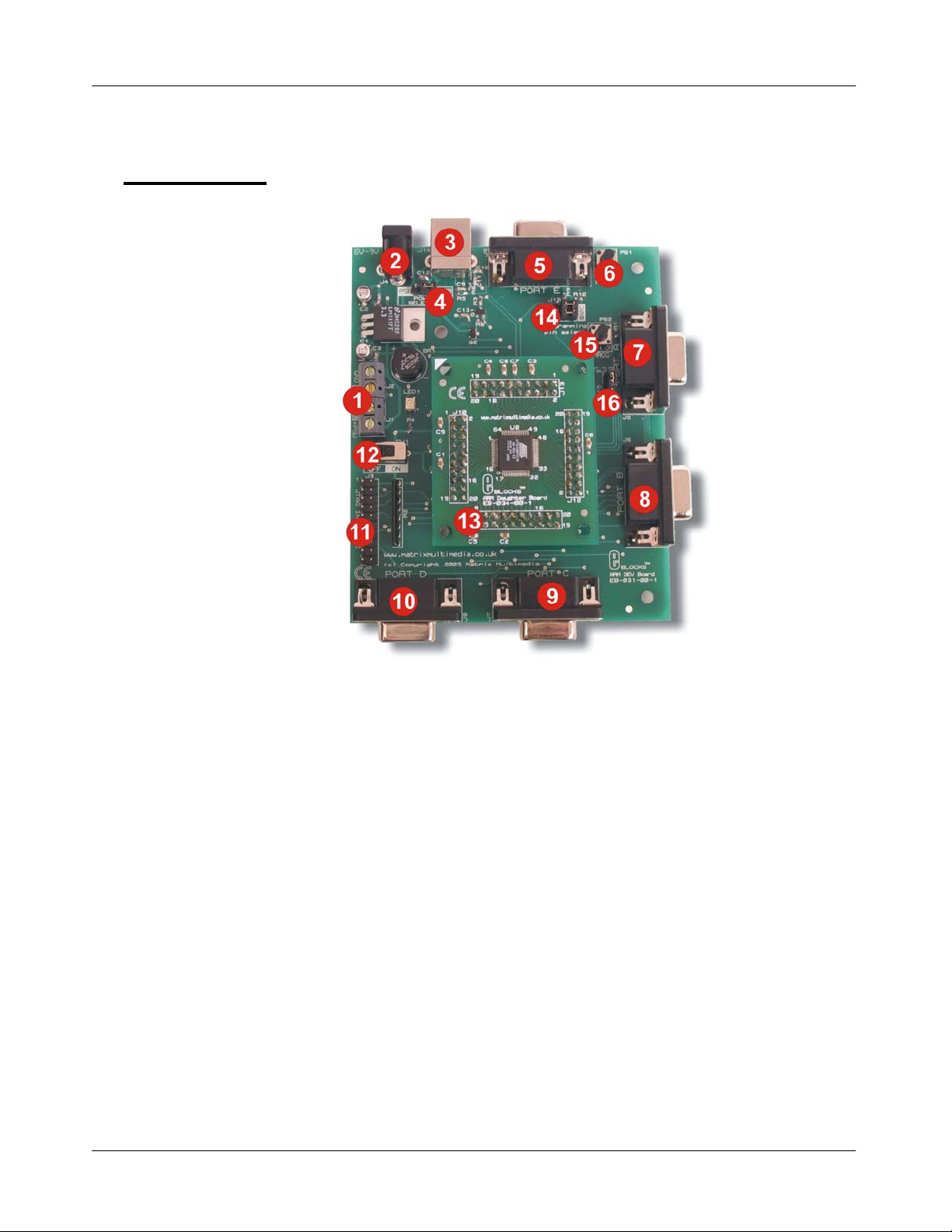
3 Board layout
E-blocks™ ARM programmer and daughter board
Document code: EB185-30-1
EB18574-1.cdr
1. Screw terminals
2. Power connector
3. USB connector
4. Power selector link block
5. Port E I/O
6. Reset switch
7. Port A I/O
8. Port B I/O
9. Port C I/O
10. Port D I/O
11. JTAG interface
12. Power switch
13. ARM daughter board
14. Programming selector link block
15. Programming switch
16. Recovery selector link block
Copyright © M atrix Multimedia Limited 200 6 page 4
Page 5
4 Testing this product
The following program will test the circuit. The test files can be downloaded from www.matrixmultimedia.com
The following instructions explain the steps to test your board. The instructions assume that mLoader is installed
and functional. It also assumes that you are confide nt in sending a program to the ARM via the mLoader
programmer software.
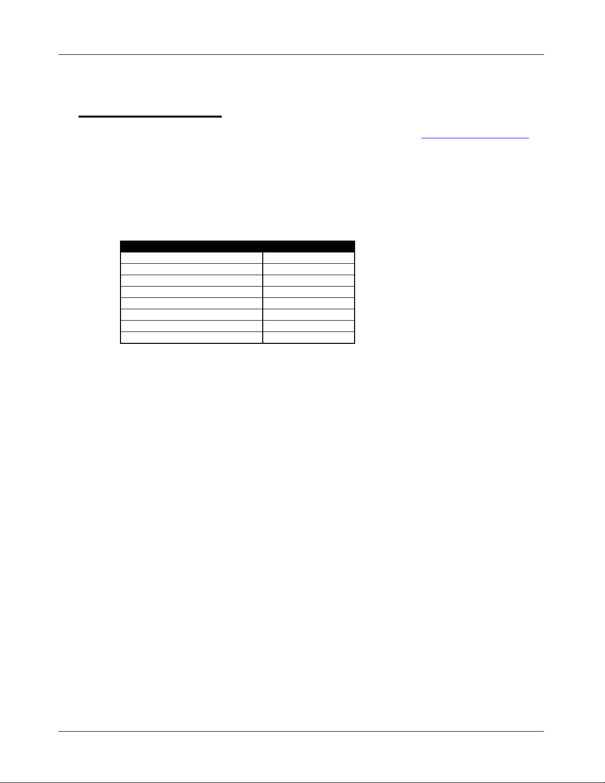
4.1 System Setup
ARM programmer board (EB031) with ARM Daughter board attached (EB034):
1 to 5 LED boards can be attached to the Ports in order to view the Test outputs.
EB031 Options Setting
Power supply External, 14V
Xtal frequency 18.432MHz
Port A LED board EB004
Port B LED board EB004
Port C LED board EB004
Port D LED board EB004
Port E LED board EB004
Test program Test.bin
E-blocks™ ARM programmer and daughter board
Document code: EB185-30-1
.
4.2 Required items:
Items required (Hardware):
• EB031 ARM board
• EB034 ARM daughter board attached to EB031
• USB Cable
• EB004 LED boards for testing port outputs.
Items required (Software):
• mLoader ARM programmer sof tware (mLoader_Setup.exe):
• mLoader ARM programmer
• Matrix ARM board USB Driver
Items required (Programs):
• Test program (Test.bin)
4.3 Initial Software Set-up.
If C for ARMs is installed then the mLoader files will have been installed already.
If not run and Install mLoader_Setup. exe which will install mLoader, the Ma trix ARM board USB driver, and the
Test.bin file.
4.4 Initial USB Driver installation
When first plugged in the board will be detected by the USB bus and reported as a Matrix board. The Add new
hardware wizard will then start asking for the USB drivers for the board. The ARM Boar d USB drivers are preinstalled as part of C for ARMs and the mLoader setup. Select automatic and the drivers should be found
automatically. If not then point the driver installer to the ‘USB Driver’ folder installed as part of mLoader
(C:\Program Files\Matrix Multimedia\mLoader\ USB Driver by default).
Copyright © M atrix Multimedia Limited 200 6 page 5
Page 6

4.5 The Test program
1) Run the ‘ARM Test Program’ shortcut from the Matrix Multimedia\mLoader program group.
The ARM Test program will then appear ready to download the test program.
2) Alternatively open the File ARM_TEST.BIN from the mLoader\ARM_TEST folder in m Loader and send the
program.
3) Whilst pressing down the PROG butto n switch (PB2) tap the RESET (P B1) button switch.
This will put the ARM board into programming mode. Release the PROG but ton switch.
4) The LEDs, if attached, will alter to signify programming mode – usually all on.
5) Once the program is sent press the RESET (PB1) button to leave Programming mode and run the test program.
6) Close the ARM_TEST program.
4.6 ARM Test program details
ARM Test program has two stages which are repeated continuously.
1) LEDs on each port light in alternate pairs creating a 1-0-1-0 to 0-1-0-1 pattern.
The pattern repeats 5 times
2) The entire port flashes on and off.
The pattern is repeated 5 times.
3) Check on each port to see that both the alternating pattern and the flashing pattern are correct.
(Excluding B5, D4 and E4-7 – see notes below).
4.7 Important Notes:
• Pins B5 and D4 are used with caution (they are USB pins and using them causes USB issues).
• Port E only uses pins 0-3. Pins 4-7 are analogue only ports which are not used in this test.
• The User test requires the ARM board to have the Matrix OS program loaded onto the ARM device.
If the Matrix OS program has not been loaded, or has been overwritten please refer to the Re-flashing the EB185
ARM Board section in the EB185-30 Technic al datasheet.
If the board is listed as a Matrix board in Hardware manager, and when first plugged in, then the Matrix O S is
correctly loaded.
E-blocks™ ARM programmer and daughter board
Document code: EB185-30-1
Copyright © M atrix Multimedia Limited 200 6 page 6
Page 7

5 Circuit description
The ARM Board solution is made up of two parts:
• A mother board (ARM Board EB031) that allows A RM devices to be programmed and the program to be
executed ‘seamlessly’
• The ARM daughter board (EB034) that houses the ARM d evice on a simple to use board. This allows the user
to program the device using the A RM Board (EB031) and then either use this daughter board in either the A RM
board (EB031) for development, or to easily use the ARM daughter board in another project.
The ARM Board (EB031) acts as a programmer and a development board allowing the powe rful A RM process or to
be used with other E-Blocks. The following is a description of the features that make up this board.
5.1 Power Supply
The board is normally operated from an external regulated DC power supply of 6V – 9V. This allows full operat io n
including programming.
The board has two modes of power supply; either from an external regulated DC power supply or powered using the
computer via the USB port. The external power supply is specified as 6 – 9V regulated DC power supply. When
using the USB port to power the board, the user must be aware of the limitati ons for the use of this USB port – for
example the limited current that can be supplied via USB (approx 100mA).
The jumper link system, J16, allows the user to decide on the source of the power supply. If using an external
power supply the jumper should be positioned to the left hand side of the jumper system labelled ‘PSU’. If using
USB power place the jumper on the right hand side of the jumper system. LED1 indicates that power is supplied to
the board from either the external power supply or the USB cable.
Please note that both USB and the PSU cables should be removed for the ARM b oard BEFORE changing the
position of this jumper.
Remember that other E-blocks will have to receive 3.3V by placing a connecting wire from the “+V” screw terminal
of the ARM Board to the “+V” screw terminal of each E-Block that requires a voltage. Also the user should ensure
that all the E-Blocks that they are using ar e 3.3V compatible.
E-blocks™ ARM programmer and daughter board
Document code: EB185-30-1
5.2 Programming (hardware)
The ARM Board connects to a personal computer via the USB socket. Any USB socket on the PC can be used. The
host ARM device is set-up to communicate with the USB bus and the programming circuitry. The board uses
MOSFET transistors to detect the USB bus, which allows the board to be programmed.
The board has a connection (10 + 10 DIL PCB header pins) that allows the ARM device to be program m ed via an
external programmer using the JTAG pin s available on the ARM device. This is a standard JTA G connection.
DIL Sockets and I / O Ports
The ARM board uses an external ARM daughter board. This daughter board enables the ARM board to be both a
development board and a programmer. This means that the user can either use the ARM daughter board in the
ARM Board for development, or for programming the daughter board which can then be used in other projects.
The ARM board connects to the ARM daughter board (EB034) via four DIL PCB sockets (10 + 10). These connect
all the ARM device signals to the ARM daughter board, thus allowing program ming an d use of all the functio ns
available on the ARM device.
The ARM Board has 5 I/O ports, in the form of 9-way D-type connectors. These allow the ARM Board to be fully
compatible with the E-Blocks range. The first four D-type connectors (J5-8) connect all 32 general-purpose I/O
from the ARM device. Most of these general-purpose I/O pins have multi ple functi ons – such feature s as SPI,
Copyright © M atrix Multimedia Limited 200 6 page 7
Page 8

USART communication and analogue to digitial converters. Please see the datasheet of the actua l ARM device that
you are using for complete list of functions (www.atmel.com ).
The ARM device has four dedicated analogue to digital converters and four genera l-purpose I/O with analogue
functionality. Therefore all these eight signals have been grouped together, on the fifth d-type connector (J9), which
can be used as a fully analogue port.
Please note that the four general-purp ose I/O are also available on the another D-type connector (J8) and care
must be taken to ensure that these signa ls are not connected to any other device whilst using them on these fully
analogue port (J9).
A full table of I/O connections is provided below.
5.3 Programming (software)
There are two ways of getting the ARM board into programming mode:
With the power to the board on press and hold down the PROG button switch. Then quickly press and release the
RESET button switch. If your drivers are set up then you will hear Windows give a double tone to indicate a USB
device has been discovered.
If you have used D4 or B5 as an output then you may find that the driver gets disassociated. In this case you can use
this alter nate method:
Turn power to the ARM board off using SW 1. Press and hold the PROG button switch down. Turn power on with
SW1, and less than half a second after release the PROG button switch.
E-blocks™ ARM programmer and daughter board
Document code: EB185-30-1
5.4 Reset Push Button
PB1 provides a reset by pulling the NRST pin low. This will reset the ARM device thus enabling any pr ogram to
restart.
Please note that the NRST can be programmed so that the reset pin will not function as a reset. See the datasheet for
the ARM device that you are using for more details on disabling the NRST as a reset.
5.5 Frequency Selection
The clock signal for this board is generated from either an internal RC clock signal or the on-board external crystal.
The on-board crystal is set to 18.432MHz as this enab les the USB synchronisation speed to be correct – as stated by
the software specification.
The device can also use an internal PLL to set the freq uency for the device. Please see the datasheet of the device
for further information regarding usi ng the PLL.
Copyright © M atrix Multimedia Limited 200 6 page 8
Page 9

6 Re-flashing the ARM Board
6.1 When to re-flash
Re-flashing is only required if the Matrix ARM OS has been deleted or overwritten, or if an updated Matrix OS file
has been released. Re-flashing should o nly be carried out when specifically required a s errors and complications may
cause the ARM board to stop functioning until properly re-flashed.
In our experience the device can need re-flashing if you reset the ARM half way through a programming cycle – to
prevent this please ensure that you give the PC sufficient time to download your program. The symptoms here are that
the ARM board appears to be dead and a PROG button with RESET button activation does not work, and neither does
a power up PROG button activation work.
General programming is performed without requiring re-flashing. Please refer to the mLo ader documentation for
general programming instructions.
If the ARM is a new device it may r equire the default ARM drivers.
These drivers are installed by SAM-BA. Please install SAM-BA before installing the USB drivers for the ARM
Board.
E-blocks™ ARM programmer and daughter board
Document code: EB185-30-1
6.2 Required items:
• SAM-BA ARM Re-flash software
Available on ELSAM 2.0 or later and from AT MEL (www.atmel.com
• Re-flash programs (ARM_MM.bin and test.bin)
6.3 Set-up
The ARM board requires re-flashing to put the Matrix ARM OS onto the ARM board.
1. Re-flashing can be done with USB power only.
2. Check J16 Power selector set to USB
3. Check J18 Programming jumper set to USB
4. Check J15 TST jumper set to Default
5. Plug the board into the PC and turn the power switch SW1 to ON.
6. Check that the Green Power LED is lit.
6.4 Re-flashing process
1. Place the TST jumper (J15) to test position – i.e. the bottom pins, straddling the Default box border.
Leave for at least 8-10 seconds.
2. Move SW1 to OFF and replace the TST jumper to the Default position.
3. Move SW1 to ON.
4. Open SAM-BA.
5. Find the USB board in SAM-BA
Select - AT91SAM7S128-EK and click on USB Connection.
A programming dialogue should now a ppear.
6. In the Middle of the dialogue are the Browse button (1) to locate files, the memory address location (2),
and the Send button.
).
Copyright © M atrix Multimedia Limited 200 6 page 9
Page 10

E-blocks™ ARM programmer and daughter board
Document code: EB185-30-1
7. Send the test file:
o Browse to (1) and open file test.bin in the ‘C:\program files\Matrix Multimedia\mLoader\Reflasher
files’ folder.
o Set the memory location (2) to 0x100000.
o Send the File
o Select OK to any Unlock zone/regions messages.
8. Send the Main file:
o Browse to (1) and open file ARM_MM.bin in the ‘C:\program files\Matrix
Multimedia\mLoader\Reflasher file s’ folde r .
o Set the memory location (2) to 0x119000.
o Send the File
o Select OK to any Unlock zone messages.
9. Move SW1 to OFF
10. Add LED boards
11. Move SW1 to ON.
12. The LEDs should now be showing alternate pairs creating a 1-0-1-0 to 0-1-0-1 pattern.
The ARM board should now be ready for testing.
Use the test routine detailed earlier to test the ARM board is correctly re-flashed and ac cepting programs from
mLoader.
Copyright © M atrix Multimedia Limited 200 6 page 10
Page 11

7 Port and Pin list
E-blocks Ports ARM pin name ARM pin Notes
A0 PA0 48
A1 PA1 47
A2 PA2 44
A3 PA3 43
A4 PA4 36
A5 PA5 35
A6 PA6 34
A7 PA7 32
B0 PA8 31
B1 PA9 30
B2 PA10 29
B3 PA11 28
B4 PA12 27
B5 PA13 22 USB Pin
B6 PA14 21
B7 PA15 20
C0 PA24 / RTS1 23
C1 PA26 26
C2 PA27 37
C3 PA28 38
C4 PA25 / CTS1 25
C5 PA23 15
C6 PA22 / TXD1 14
C7 PA21 / RXD1 11
D0 PA17 / AD0 9 Also on E0 - Analogue Pin
D1 PA18 / AD1 10 Also on E1 - Analogue Pin
D2 PA19 / AD2 13 Also on E2 - Analogue Pin
D3 PA20 / AD3 16 Also on E3 - Analogue Pin
D4 PA16 19 USB Pin
D5 PA29 41
D6 PA30 42
D7 PA31 52
E0 PA17 / AD0 9 Also on D0 - Analogue Pin
E1 PA18 / AD1 10 Also on D1 - Analogue Pin
E2 PA19 / AD2 13 Also on D2 - Analogue Pin
E3 PA20 / AD3 16 Also on D3 - Analogue Pin
E4 AD4 3 Analogue Pin
E5 AD5 4 Analogue Pin
E6 AD6 5 Analogue Pin
E7 AD7 6 Analogue Pin
E-blocks™ ARM programmer and daughter board
Document code: EB185-30-1
7.1 Notes:
• The ARM has a 32 bit IO register and 8 Analog ue input lines.
• On the E-blocks ARM board the 32 bit register has been broken down into four ports – Ports A, B, C and D.
• Four of the analogue lines use pins in the 32 bit digital IO port. Four of the analogue lines are separate analogue
• Port E contains the 8 Analogue input lines.
• Pins B5 and D4 are used in USB Communications.
Copyright © M atrix Multimedia Limited 200 6 page 11
The pin to port allocation does not correspond directly 0-31 with Ports A-D due to the ne ed to place serial
communications pins on the same port (Port C). Please refer to the above Port and Pin list when worki ng with
the 32 bit IO register.
only lines.
This means that Port E Pins E0-E3 duplicate those of P ort D pins D0-D3.
Pins E4-E7 are analogue lines only, not gene ral IO.
Signals on these lines may affect the USB bus causing erroneous activations of the USB New device added
wizard. To prevent this either do not use Pins B5 and D4, or move the Programming Pin Select jumper (J18) to
the IO position whilst running the program (move it back to USB for programming).
Page 12

Page 13

Appendix 1 – Circuit diagram
Page 14

Appendix 1 – Circuit diagram
Page 15

Appendix 1 – Circuit diagram
 Loading...