

Page 1

DS213 Mini Oscilloscope
User Manual
This user man ual i s bas ed on AP P V1.2
V1 .0
A
B
DS2 13
Page 2

Contents
Imp ort ant Sa fety I nfo rmat ion
I. Ov erv iew
II. I nte rfac e Intr odu ctio n
III . Get ting S tart ed
IV. Ge nera l Inspect ion
V. Fun ctio n Inspect ion
VI. B att ery Di spos al
VII . Technic al Sup port
P1
P3
P7
P15
P23
P24
P25
P26
Page 3
Safe ty Statement
•Read carefu lly a ll th e fol low ing safety pre cau tio ns to a voi d personal inj ury a nd
prevent damage t o the d evi ce or a ny products co nne cte d to it . Failure to follow t hes e
safety inst ruc tio ns co uld r esult in perso nal i nju rie s or ri sk of fire.
•Follow all the saf ety p rec aut ions to preven t pot ent ial r isk s. Avoi d fir e and p ers onal
injuries.
•Use proper power c ord . Ple ase u se power cord sp eci fie d for t his p roduct and cer tif ied
for your coun try /di str ict of use.
•Connect and disc onn ect p rop erly. Do not c onn ect o r disconnect prob e or te st le ads
while they ar e con nec ted t o vol tage source. B efo re yo u con nec t or disconnec t cur ren t
probes,pl eas e dis con nec t power to the cir cui t und er te st.
•Observe all t he te rmi nal r ati ngs. To avo id fire or shock haza rd, ple ase d o not measure
signals abo ve. P lea se re ad th e User Manual ca ref ull y to le arn m ore about rati ngs
before conn ect ion .
•Do not operate in a hu mid e nvi ron ment.
•Do not operate in a po ten tia lly i nflammable /ex plo siv e atm osphere.
•Please keep the de vic e sur fac e clean and dry.
1
Page 4

Opera tin g Environm ent
Operating
Environme nt
Temperature
Humidity
Requireme nt
Operating C ond iti on
Non-operatin g Con dit ion
+0°C to+50°c
-20°c to +60°c
High Tempe rat ure:4 0°C to 50°C, 0% to 90%R H
Operating C ond iti on
Low Temp era ture : 0° C to 40°C, 1 0% to 9 0%R H
High temper atu re:40 °C to 6 0°C , 5% to 95%RH
Non-operatin g Con dit ion
Low temperatur e:0° C to 4 0°C , 5% to 9 5%RH
2
Page 5

I. Over vie w
DS213 is a “5-t rac k, 4- wav e line” digital sto rag e osc ill oscope for genera l-p urp ose e lectronic
engineering ta sk an d it is b ase d on ARM Cortex M3 co re. D S21 3 use s FPG A to ma nag e ext ern al
ADC’s co ntr ol an d data cache mode. It p rov ide s 4 app lication partit ion s for l oad ing and upgrading
up to 4 diff ere nt ap plication firmw are . It al so ha s built-in 8MB USB fl ash d riv e for s toring waveform s
and upgrading sy ste m fir mwa re.
1. Perf orm ance param ete rs
1. 1 Perform anc e par ame ter s
Maximum sam pli ng ra te
Analog bandwid th
Analog input imp eda nce
Coupling
Maximum input vo lta ge probe
: AC/DC
: 100M Sa/s
: 15M
: 1MΩ
: ±40V(X1 )
±400V(X10 ) probe
3
Page 6

Horizonta l sen sit ivi ty stepping
Vertical sensit ivi ty stepping
: 100nS/Div -1S /Di v(1 -2-5 )
: 10mV/Div- 10V /Di v(1 -2-5 )
Standard digit al ch ann el in put impedance: 10 0KΩ
Max digital chan nel i npu t vol tage: +5V
1.2 Functio nal iti es
Tri gge r mode
Tri gge r mode
Auto measur eme nt
: Edge trigge r, pul se wi dth t rig ger
: Auto, Normal , Sin gle , Slo w
: Frequency, C ycl e, Duty, Pos iti ve Pu lse W idth, Negative Pu lse W idt h, Vp p/
Vrm s/Vavg/V max /Vm in
Inbuilt sig nal G ene rat or
: 10Hz~8MHz squ are w ave ,10 Hz~20 KHz sine wave/ tri ang ula r wav e/
sawtooth wa ve
1.3 Product p ara met ers
Storage Inbuilt 8MB U d isk s tor age f or wa veform data an d ima ges
:
: Micro USBBattery Internal 10 00m Ah Li thi um ba ttery, ext ern al port
:
Display Color TF T LCD display (240X 400 p ixe ls)
Dimension
: 99.5×59×1 3.5 mm
4
Page 7

2. Butt ons a nd Interfa ce
Shortcut fu nct ion s: + Scre enshot
DS2 13
▲
B
+
●
+
ON
Save system s ett ing
Auto calibra tio n
A
5
Page 8

Button
A
B
CH A
CH B
CH C
CH D
OUT
USB
ON
Function
Run/Pause
(K1 key)
Display Menu(K2 ke y)
Switch Channel(K 3 key)
Fn Combinat ion K ey (H old t his k ey and roll
Encoder A to fa st ad jus t data)(K4 key)
Adjust/Chang e Opt ion
Cursor, movible f rom A to U
Analog Input Cha nne l A
Analog Input Cha nne l B
Analog Input Cha nne l C
Analog Input Cha nne l D
Wav efo rm Output Channel
Charging/Dat a Con nec tio n
Power Butto n
6
Page 9
II. Int erf ace Introd uct ion
1. Chan nel s and Menu Col ors
Blue for Chan nel A
Yell ow fo r Channel B
Purple for Ch ann el C
Green for Cha nne l D
Orange for co mmo n men u
7
Page 10

2.Hom e scr een introd uct ion
A B C D E F G H I
J
K
L
M
N
O
P
Q
U
ST
8
R
Page 11

Menu
A
B
C
D
Icon
RUN
AC
1V
AC
1V
CH(C)
Item
RUN/HOLD
AC/DC/--
10mV—10V
(1-2-5 sequenc e ste p)
AC/DC/--
10mV—10V
(1-2-5 )sequence step
CH(C)/
(A+B)/(A- B)/ (C& D)/
(C|D)/INV A/ INV B /--
Options
(Operatin g sta tus )Ru n/P ause
Battery sup ply
(Channel A)AC/ DC c oup lin g /Hi de
Voltage value per g rid
(Channel B)AC/ D C cou pli ng H ide/
Voltage value per g rid
Choose C hann el C for inpu t
Adding o f wave form s of Ch anne l A & Channel B
Subtra ctio n of wav efo rms of C hann el A & Chan nel B
AND oper atio n of wav efo rms of C hann el C & Ch anne l D
OR op era tion o f wave for ms of Ch anne l C & Cha nnel D
Invers ion of w avef orm o f Chan nel A
Inv ers ion of w avef orm o f Chan nel B
9
Hide
Page 12

Menu
E
F
G
H
Icon
CH (D)
Xpos
Vtrg
Item
CH (D)/REC_ A/REC_B /
REC_C/ REC_D/--
Xpos
Vtrg
,
,
<Vt >V t <TL, , ,
>TL <T H >TH, ,
10
Options
Choose C hann el D for inpu t
:
REC_A Reload t he las t wave for m save d in Ch_ A
:Reload t he las t wave for m save d in Ch_ B
REC_B
REC_C:Re load t he last wav efor m save d in Ch _C
REC_D:Re load t he last wav efor m save d in Ch _D
Choose wavefor m pos iti on: r oll Encoder A
to observe wa vef orm s aro und t riggering
Tri gge r line: roll Encode r A to ad just trigger
voltage val ue, p res s Swi tch b utton “●” t o
Tri gger m ode fa lli ng edg e trig ger /
sma lle r than t rigg er/ larg er tha n tri gger /
negati ve pul se width sm alle r than t rig ger/
negati ve pul se width la rger t han tr igg er/
positi ve pul se wid th sm alle r than t rig ger/
positi ve pul se width la rger t han tr igg er
--:Hi de
choose channel
rising e dge tr igge r/
Page 13

Menu
Icon
Item
Options
AUTO
I
10uS
AUTO/N ORM /SI NGL/SLOW
100nS—1S(1-2-5 s tep pin g)
Sqr/Sin/Tri/Saw(Vpp= 3V)
Sqr
J
50KHz
(Sqr)10Hz— 8MH z
(Sin/Tri/Saw) 10Hz—20 KHz
K
L
M
Yp
V1
V2
Yp
V1
V2
11
Auto/Norm al/ Sin gle /Sl ow Scan
Tim eba se (x-axis voltag e per g rid )
(Wa vef orm output) Squar e wav e/
sine wave/tria ngu lar w ave /sawtooth wa ve
1-2-5 stepp ing f or lo wer t han 1 MHz
2-4-6-8 ste ppi ng fo r hig her t han 1MHz
Wav efo rm position line: r oll E nco der A
to adjust pos iti on li ne, p res s Switch butto n
Vernier V1: Visual voltage up per l imi t,
press Switc h but ton ● t o dis pla y/hide“ ”
Vernier V2: Visual voltage lo wer l imi t,
press Switc h but ton ● t o dis pla y/hide“ ”
● to switch “ ”
Page 14

Menu Ic on Item
N
O
P
Q
R
S
T0
T1
T2
CAL
Duty
Frqn
T0
T1
T2
CAL
TwH TwL △T
, , ,
Frqn,Cycl,D uty
Options
Choose wavefor m dis pla y win dow: roll
Encoder A to ch oos e wav eform stored in
differ ent p osi tion to display in cu rre nt wi ndo w
Tim e mea surement cursor T1:
A to adjust Vernier T1 's value, press swi tch
Tim e mea surement cursor T 2:Rol l Encoder A to
adjust Vernier T2 's value, press swi tch b utt on to
button to dis pla y/h ide
display/hide
Roll Encoder
Manual calibra tio n: ro ll En coder A to le ver
calibrati on, p res s swi tch b utton to switc h
time measur eme nt ar ea of c han nel A/B
TwH: High level tim e of si ngl e cyc le
TwL: Low level time o f sin gle c ycl e
△T: Time length of Vernie r T1 and T2 (△T=T 1-T 2)
12
Frqn: Signa l Fre que ncy
Cycl: Signa l Cyc le
Duty
Page 15

Menu
T
U
Icon
Vrm s:
+0.00uV
Vp-p:
+0.00uV
Item
, ,
Vavg Vmax
, ,
Vmin Vrm s
, ,
Vp-p △V
,
Vtrg Vb at
3. Menu I ntr oduction
Under home scree n, pr ess m enu b utton
to enter menu o pti ons ; pre ss me nu button
again to exit.
Options
Vavg : Aver age Voltage
Vmax: Max Volt age
Vmin: Min Voltage
Vrm s: Ro ot-Mean-Squar e Volt age
△V: Vol tag e Value of Vern ier V 1 and V 2 (△V=V 1-V2)
13
Vp-p: Peak- to- Pea k Volt age
Vtrg: Trigge r Lin e Volt age o f X-a xis
Vbat:Batter y vol tag e
Page 16

Options
SaveWav00 0
LoadWav00 0
SaveBuf 000
SaveCsv 000
Volume
0%~100%
LcdBk
10%~100%
PwrDnT
Off~60m
Functions
Save dat file t o bui lt- in U di sk
Load dat file
Save buf file ( sam pli ng da ta in
buffer ing a rea ) to built-in U disk
Save csv f ile (e xpor t sam plin g data
in buffering a rea) t o built-i n U disk
Adjust buzzer vo lum e
Adjust back lig ht br igh tne ss
Adjust stan dby t ime
14
Operation
Roll Encoder A to ch oos e file number,
Roll Encoder A to ch oos e file number,
Roll Encoder A to ch oos e file number,
Roll Encoder A to ch oos e file number,
press K3 to con fir m
press K3 to con fir m
press K3 to con fir m
press K3 to con fir m
Roll Encoder A to ad jus t volume
Roll Encoder A to ad jus t backlight
brightness
Roll Encoder A to ad jus t standby time
Page 17

III. Ge tti ng Started
1. Oper ati on Tec hniques
)
1 When noise and rip ple w ave s nee d to be observed with s ign al ac ces sed, AC ge ar sh oul d be
selected;
2)Vernier V1 and V2 c an be u sed t o mea sure the voltage di fference betwee n any t wo po int s;
3)Vernier T1 a nd T2 can be used to m eas ure t he ti me differ enc e bet wee n any two points;
2. Ap plication Cas es:
Case 1. Measure si mpl e sig nal s
Observe a cer tai n unk now n sig nal, rapidly s how a nd me asu re it s frequency an d pea k val ue.
Operating s tep s:
1)Connect th e bot tom l ine , and c onnect the pro be of C han nel A (or C han nel B) to the meas ure d
point of the ci rcu it;
2)Set Channel A (or C han nel B) as “AUTO” m ode a nd “DC” coupling, a dju st (h ori zontal) time
scale and (ve rti cal ) vol tag e scale to prese nt a cl ear s ign al di splay;
15
Page 18

3)Adjust “Vt rg” t o pre sen t sta ble signal dis pla y;
4)Select mea sur ing d ata , suc h as Vpp (peak-t o-p eak v olt age ), Vavg ( ave rag e vol tage), FRQ
(frequenc y), e tc.
See the follo win g pic tur e for m easurement d isp lay :
16
Page 19

Case 2. Captu re si ngl e sig nal
The advanta ge an d fea tur e of di gital oscill osc ope i ncl ude s convenient ly ca ptu rin g ape riodic
signals like pul ses a nd bu rrs . If a certain sin gle s ign al is c apt ured, prior kn owl edg e is ne ede d
before sett ing t rig ger l eve l and trigger ed ge. F or ex amp le, i f the pulse is a TTL le vel l ogi c sig nal ,
the trigger l eve l sho uld b e set a s “2V”, trigge r edg e as “r isi ng ed ge”. If the cond iti on of m eas ured
signal is uncert ain , com mon t rigger model s can b e ado pte d fir st to observe so a s to de ter min e
specific tr igg ers .
1)Connect the pr obe o f Cha nne l B to the measuri ng po int o f the c irc uit;
2)Set the tri gge r: se t pos iti on H as “ ” (rising ed ge tr igg er) , position I as “SING L”( sin gle t rigger),
and trigger as “AC ” (AC c oup lin g);
3)Adjust ho riz ont al ti me ba se and vertica l gea r to pr ope r ran ge;
4)Adjust G “Vtr g” an d sel ect p rop er trigger lev el;
5)Press“ ” run bu tto n and w ait f or the appearance o f sig nal s tha t caters to trigger c ond iti ons . If
a certain sig nal r eac hes t rig ger level set, i t wil l be sa mpl ed an d then showed on t he sc ree n.
This functi on ca n be us ed to c apt ure the occasi ona l eve nts , suc h as large ampli tud e sud den b urr s:
set the trigg er le vel r igh t hig her than norma l sig nal , pre ss “ ” button then wait . Whe n bur rs oc cur,
DSO will auto mat ica lly t rig ger and record t he wa vef orm s aro und the occurr enc e for o bse rvi ng. See
the picture b elo w.
17
Page 20

This functi on ca n be us ed to c apt ure the occasi ona l eve nts , suc h as large ampli tud e sud den b urr s:
set the trigg er le vel r igh t hig her than norma l sig nal , pre ss “ ” button then wait . Whe n bur rs oc cur,
DSO will auto mat ica lly t rig ger and record t he wa vef orm s aro und the occurr enc e for o bse rving. See
the picture b elo w.
18
Page 21

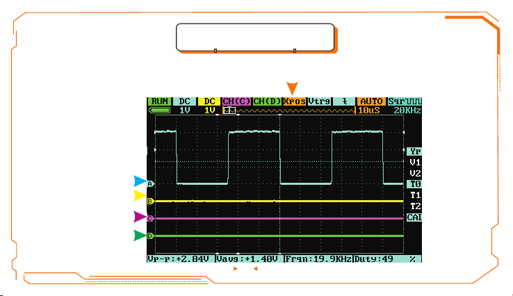
Case 3. Use a Vernier t o mea sur e sig nal
Vernier can be used t o rap idl y mea sure waveforms in t erm s of ti me an d voltage.
A.Measure th e per iod o f the t hird peak of signal s our ce
Operating s tep s:
1)Roll Encoder B to m ove c urs or to p osition O (T1) ;
2)Roll Encoder A to pla ce Ver nie r T1 to the sec ond p eak o f the s ign al;
3)Roll Encoder B to m ove c urs or to t he position P (T 2);
4)Roll Encoder A to pla ce Ver nie r T2 to the thi rd pe ak of t he si gnal; Conclusio n:
△T=50uS is the p eri od of t he th ird p eak.
B. Measure th e pea k-t o-p eak v oltage of sign al so urc e
Operating s tep s:
1)Roll Encoder B to m ove c urs or to p osition L (V1);
2)Roll Encoder A to pla ce Ver nie r V1 to t he peak of signal;
3)Roll Encoder B to m ove c urs or to p osition M (V2) ;
4)Roll Encoder A to pla ce Ver nie r V2 to t he trough of
signal; Con clu sio n: △V= 3.2 0V is the peak-t o-p eak
voltage of si gna l.
19
Page 22

Case 4. Wa veform Comparis on
REC_A functi on in p osi tio n D can b e used to compar e sig nal w ave for ms.
Operating s tep s:
1)Input kno wn wa vef orm s ign al in Channel A, press b utt on“■ ”, select “Save Wav 001”, a nd pr ess
button“●” to s ave t he wa veform, see follo win g pic tur e;
20
Page 23

2)Input wav efo rm si gna ls th at are to be compa red i n Cha nne l A, selec t “RE C_A ” in po sit ion E,
press butto n “●” to s ele ct “LoadWav001”, see follo win g pic tur e;
21
Page 24

3)Move “Yp” in p osi tion K to adjust the ho riz ont al li ne and then compare t he wa vef orm s.
See followi ng pi ctu re.
22
Page 25

IV. General Inspection
When you get a ne w DS2 13 os cil los cope, you are ad vis ed to i nsp ect t he product by th e fol low ing
steps.
● Inspect dam age s cau sed b y shi pping. If the pa cka gin g car ton or the protecti on pa d is se rio usly
damaged, ke ep th e pac kag e unt il the oscillo sco pe & ac ces sor ies pass the ele ctr ica l and t he
mechanica l tes t.
● Inspect the p rod uct .
Please cont act t he co mpa ny if the following p rob lem s occ ur:
1) product su rfa ce is d ama ged ,
2) product do esn 't wo rk pr ope rly,
3) product do es no t pas s per for mance test.
If the damage i s res ult ed fr om shipping, plea se ke ep th e pac kag e and contact th e com pan y for
repair or exc han ge.
23
Page 26

V. Function Inspection
Take a quick functio n ins pec tio n of DS213, to make sur e it wo rks n orm ally. Plea se fo llo w these
steps:
1 Switch on th e pow er bu tto n, enter the home pag e of th e DSO .
.
2. Input a stan dar d sig nal ( eg. S quare wave 20K Hz, V pp= 5V) i nto o scilloscop e's “ CH A” wi th a
probe:
1) Set the tap on t he pr obe t o X1, i nse rt the probe's M CX pl ug to “ CH A”, a nd insert the pin of pr obe
into “OUT”;
2) Check if the re is a d ist ort ion o f measuremen t and s tan dar d, calibrate if dif fer ent. Check the othe r
channels wi th th e sam e met hod .
24
Page 27

VI. Battery Disposal
FCC compliance s tat eme nt
This device i s com pli ed wi th th e regulation i n the 1 5th p art o f FCC r egulation.
Operation i s sub jec t to th e fol lowing two con dit ion s:
(1) This device ma y not c aus e har mful interferen ce, and
(2) This device mu st ac cep t any i nterference rec eiv ed, i ncl uding the interfe ren ce
that may caus e und esi red o per ation.
The CE mark is a re gis ter ed tr ade mark of Europe an Co mmu nit y. This C E mar k
shows that th e pro duc t com pli es with all the re lev ant E uro pea n Legal Direct ive s.
Do not dispos e in do mes tic e household waste
!
•This device c omp lie s wit h the W EEE Directiv e (20 02/ 96/ EC) marking requi rem ent .
This aff ixe d pro duct label indica tes t hat y ou mu st not discard this e lec tri cal o r
electroni c pro duc t in do mes tic househol d was te.
•Disposal and rec ycl ing : you m ust dispose th e min i osc ill osc ope accordin g to lo cal
law and regulati ons . As the o sci lloscope contai ns el ect ron ic building brick a nd
battery, you m ust d ispose it respect ive ly wi th ga rbage.
•Please dispose t he ba tte ry in a ccordance wi th lo cal e nvi ron mental regul ati ons .
25
Page 28

VII. Techni cal S upport
To upgrade the firmw are o f osc ill oscope, plea se ca rry o ut th e
operation belo w:
1.Open web brows er to v isi t www. minidso.com , dow nlo ad th e
newest firm war e app rop ria te to oscillos cop e to yo ur PC .
2.Hold Pause but ton a nd tu rn on D S213, to enter DFU mo de
for upgrade .
3.Use USB data cor d to co nne ct DS 213 to your PC, and a
removable hard d isk n ame d “ ” will appear on
your PC. Copy t he he x fir mwa re to t he root direct ory o f tha t dis k.
After the ext ens ion o f the f irm ware changes f rom “ .he x” to “ .rdy”,
restart DS2 13. T hen the upgrading p roc ess i s fin ished.
DFU V3_xx_x
26
 Loading...