

Page 1

Page 2
AUTION MAX AX-4030 OPERATING MANUAL
Premise
This operating manual contains important information on the functions of the AUTION
MAX™ AX-4030.
This operating manual is issued by ARKRAY, Inc.
Read carefully prior to starting up the unit.
This instrument is IVD medical device.
This product conforms to European Directive 98/79/EC.
AX-4030
3
Page 3
4
AX-4030
AUTION MAX AX-4030 OPERATING MANUAL
Introduction
Read this operating manual thoroughly before using the instrument. This operating manual gives
an outline of the instrument and the proper procedures for operation and maintenance. Follow the
instructions in this operating manual in order not to impair the protection by the instrument.
Also, keep this operating manual in an easily accessible place near the instrument.
■ TAKE THE UTMOST CARE WHEN HANDLING URINE. This instrument
uses urine as sample and an ingredient of control solutions. Urine may be
contaminated by pathogenic microbes that can cause infectious diseases.
Improper handling of urine may cause infection to the user or other
individuals by pathogenic microbes.
■ This instrument is to be operated by qualified persons only. A qualified
person is one having adequate knowledge of clinical testing and the
disposal of infectious waste. Thoroughly read this operating manual before
use.
■ Never touch the aspirating nozzle, waste box, waste box tray, trap bottle,
drain bottle, drain tubes, transport tray, introduction tray, or other parts
where the sample may adhere with unprotected hands. During cleaning or
maintenance of these parts, wear protective gloves to prevent exposure to
pathogenic microbes.
■ Discard used samples, test strips, liquid waste, parts, and instrument in
accordance with local regulations for biohazardous waste.
© 2008 ARKRAY, Inc.
• It is strictly prohibited to copy any part of this operating manual without the expressed consent of
ARKRAY, Inc.
• The information in this operating manual is subject to change without notice.
• ARKRAY, Inc. has made every effort to prepare this operating manual as best possible. Should
you discover anything strange, incorrect or missing, contact your distributor.
Page 4
AUTION MAX AX-4030 OPERATING MANUAL
Symbols
The following symbols are used in this operating manual and labels on this instrument to call your
attention to specific items.
For Your Safety
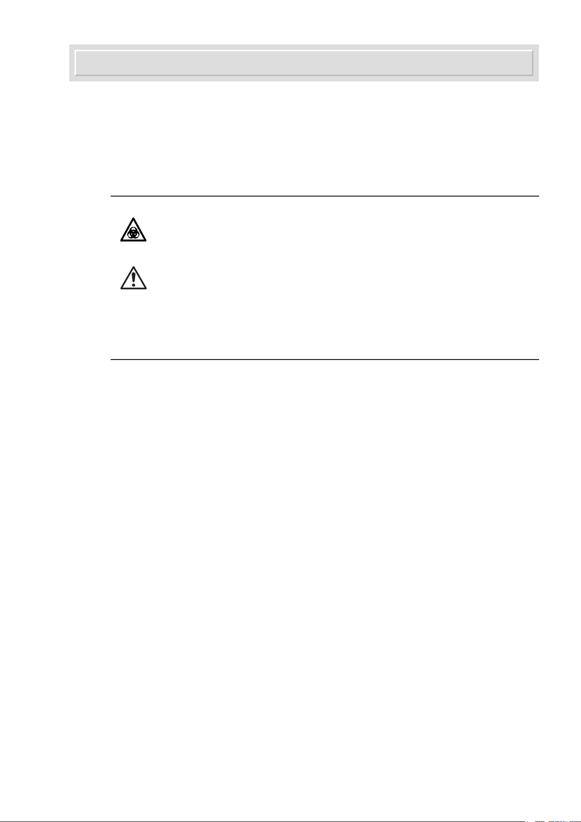
Follow the instructions given here to prevent exposure to pathogenic
microbes.
Follow the instructions given here to prevent injury and property damage.
For Optimal Performance
IMPORTANT: Follow the instructions given here to obtain accurate measurement results.
NOTE: Information useful for preventing damage to the instrument or parts, and other important
information you should keep in mind.
REFERENCE: Additional explanations that help you make the best use of the instrument, and
information on related functions.
AX-4030
5
Page 5
AUTION MAX AX-4030 OPERATING MANUAL
3
5
4
1
2
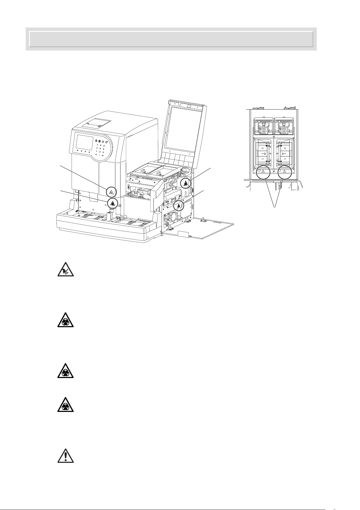
Caution Labels
This instrument has several caution labels on the areas that have potential dangers. Please learn
potential dangers warned by each label and observe the precautions described below.
■ Front
1. Sample aspirating section
The tip of the nozzle descends from here to aspirate samples. To avoid
injury, keep your hands away from here while the power is on. Also,
avoid touching the sample racks in the sampler while measurement is in
progress. Contact with moving sample racks may result in injury.
2. Front panel
The nozzle, washing bath, and other components inside this instrument
can be contaminated by urine samples. Do not touch these parts with
unprotected hands. Wear protective gloves to prevent exposure to
pathogenic microbes while cleaning these parts.
3. Trap bottle and tube
Do not touch liquid waste with unprotected hands to prevent exposure to
pathogenic microbes.
4. Maintenance section
The introduction tray, tubes and other components inside this section
can be contaminated by urine samples. Do not touch these parts with
unprotected hands. Wear protective gloves to prevent exposure to
pathogenic microbes while cleaning these parts.
5. Feeders
The test strip storage section of the feeder may move during measurement.
To avoid injury, do not touch inside the storage section when adding new
test strips to the feeder. Press the standby switch to turn off the power
before cleaning the test strip storage section.
6
AX-4030
D
Page 6
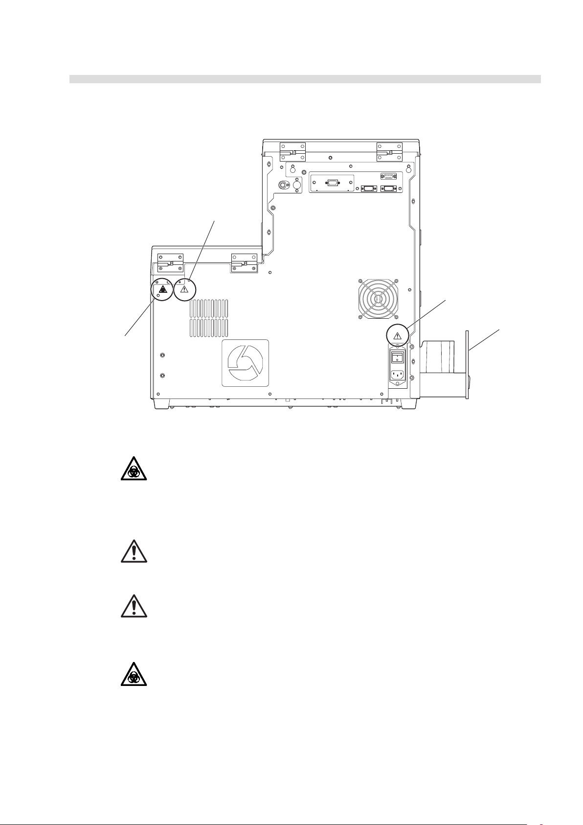
■ Rear
1
2
3
4
AUTION MAX AX-4030 OPERATING MANUAL
1. Drain joint
Liquid waste is discharged from this joint to the drain bottle. Do not touch
liquid waste with unprotected hands because the drainage contains urine
samples. When cleaning the drain joint, tube and bottle, wear protective
gloves to prevent exposure to pathogenic microbes.
2. Washing solution joint
The washing solution in the washing solution bottle goes through this
joint. Use the specified washing solution.
3. Power input terminal
The supplied power cord is plugged in here. Use of other cords may cause
electric shock or fire. The fuse holders are also located here. Prepare fuses
of the specified capacity for replacement.
4. Waste box and waste box tray
Used test strips are collected in this box. When discarding the test strips,
wear protective gloves to prevent exposure to pathogenic microbes.
AX-4030
7
Page 7
AUTION MAX AX-4030 OPERATING MANUAL
1
2
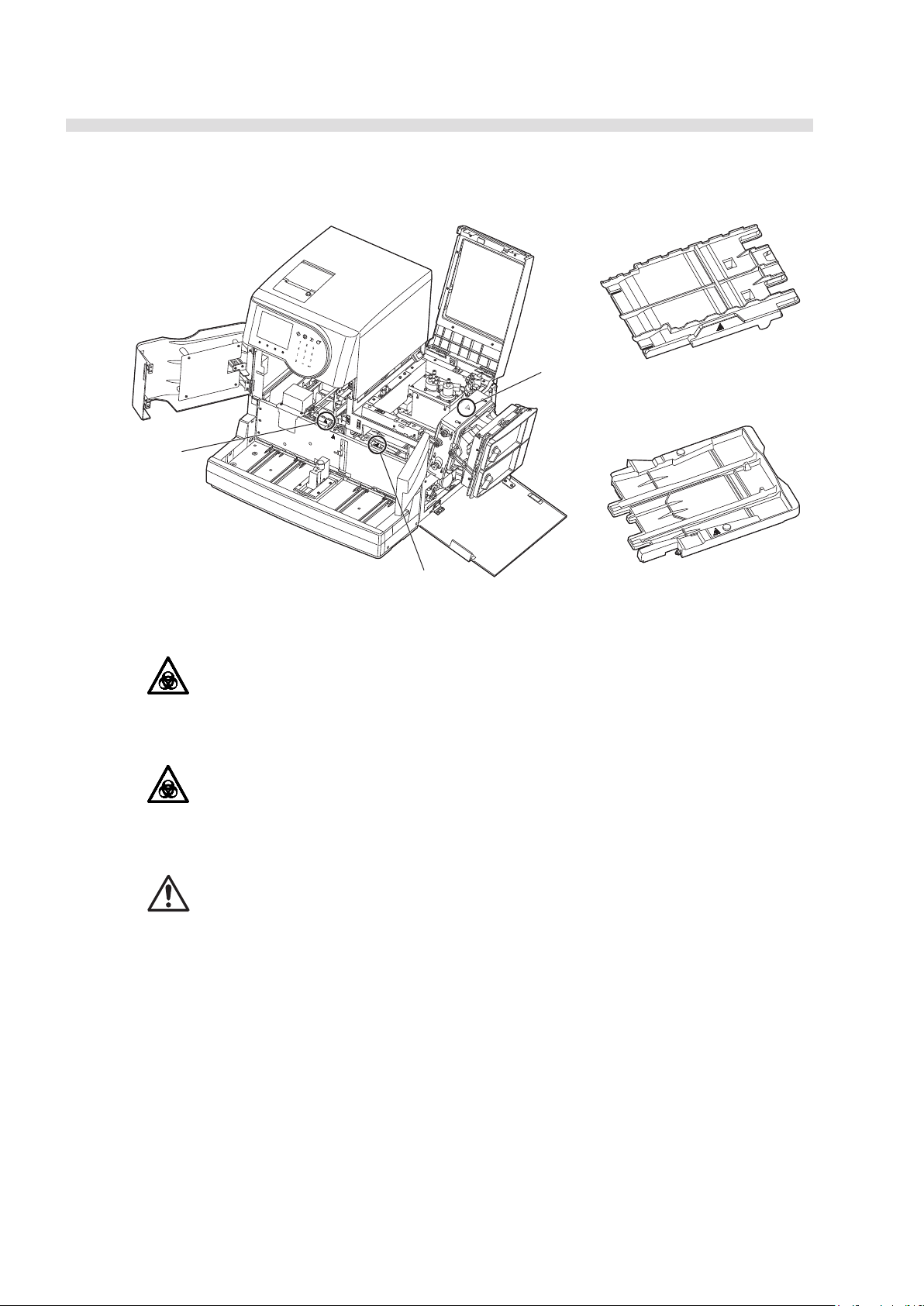
1. Transport tray
2. Introduction tray
3
■ Inside
1. Transport tray
The transport tray can be contaminated by urine samples. Do not touch
this tray with unprotected hands. Wear protective gloves to prevent
exposure to pathogenic microbes while cleaning these parts.
2. Introduction tray
The introduction tray can be contaminated by urine samples. Do not
touch this tray with unprotected hands. Wear protective gloves to prevent
exposure to pathogenic microbes while cleaning these parts.
3. Test strip storage section
Contact with the electrical circuits can damage the instrument. Do not
touch the electrical circuits.
8
AX-4030
E
Page 8
■ Washing solution bottle
1
1
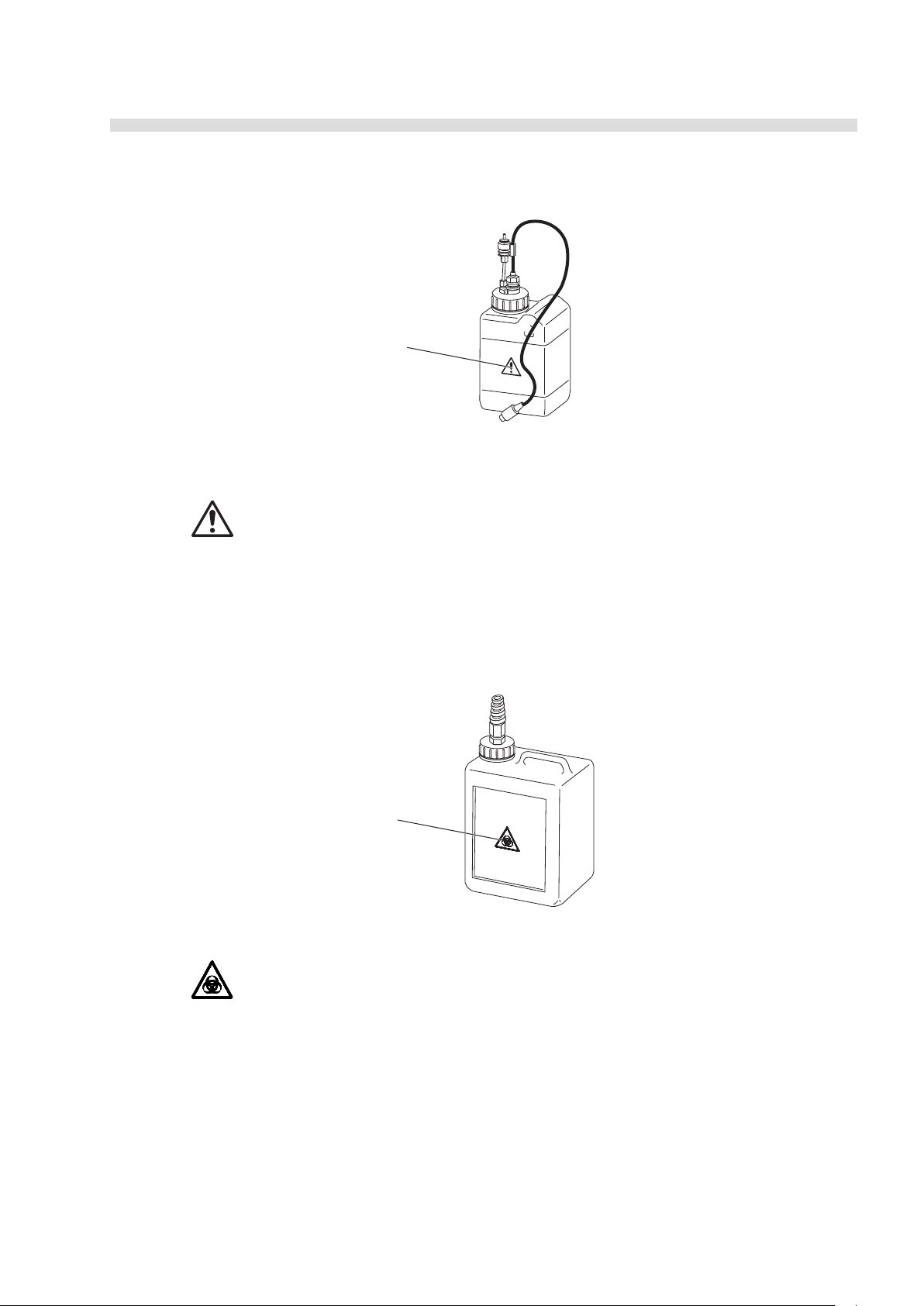
1. Washing solution bottle
Fill this bottle with the washing solution prepared as specified.
AUTION MAX AX-4030 OPERATING MANUAL
■ Drain Bottle
1. Drain Bottle
Liquid waste is collected in this bottle. When discarding liquid waste, wear
protective gloves to prevent exposure to pathogenic microbes.
AX-4030
9
Page 9

10
AX-4030
AUTION MAX AX-4030 OPERATING MANUAL
G
Table of Contents
Premise .......................................................................... 3
Introduction ..................................................................... 4
Symbols .......................................................................... 5
Caution Labels................................................................ 6
Table of Contents ......................................................... 10
Chapter 1 Before Use
1.1 Outline of the AX-4030 .......................................1-2
1.1.1 What You Can Do with the AX-4030 ................ 1-2
1.1.2 Features ...........................................................1-3
1.1.3 Specifications ..................................................1-5
1.1.4 Measurement Principle .................................... 1-6
1.1.5 Rank Table ..................................................... 1-11
1.2 Unpacking .........................................................1-13
1.2.1 Instrument ......................................................1-13
1.2.2 Sampler .......................................................... 1-13
1.2.3 Accessories .................................................... 1-14
1.2.4 Accessory Case .............................................1-15
1.3 Components ...................................................... 1-16
1.3.1 Front View ......................................................1-16
1.3.2 Rear View ....................................................... 1-17
1.4 Installation......................................................... 1-18
1.4.1 Precautions in Instrument Installation ............1-18
1.4.2 Unlocking the Instrument ............................... 1-20
1.4.3 Attaching the Sampler .................................... 1-23
1.4.4 Installing the Washing Solution Bottle ............ 1-26
1.4.5 Installing the Drain Bottle ...............................1-28
1.4.6 Installing the Waste Box ................................. 1-29
1.4.7 Connecting the Power Cord and
External Devices ............................................1-30
1.5 Starting Up ........................................................1-31
1.5.1 Turning On the Power for the First Time ........ 1-31
1.5.2 Setting up the Printer and System Clock ....... 1-33
1.5.3 Turning Off the Power ....................................1-34
1.6.7 Relocating the Instrument ..............................1-39
1.7 Basic Operations .............................................. 1-40
1.7.1 Components on the Operator Panel .............. 1-40
1.7.2 Screen Configuration ..................................... 1-41
1.7.3 Menu Operations and Examples .................... 1-42
Chapter 2 Measurement
2.1 Before Making Measurements........................... 2-2
2.1.1 Flowchart of Operational Procedure ................ 2-2
2.1.2 Measurement and Calibration ..........................2-3
2.1.3 Measurement Terminology .............................. 2-4
2.1.4 Sample Containers and Sample Racks ........... 2-7
2.2 Measurement Precautions ................................. 2-9
2.2.1 Handling the Instrument ...................................2-9
2.2.2 Handling Samples ..........................................2-10
2.2.3 Handling Test Strips ....................................... 2-11
2.3 Preparation for Measurement.......................... 2-12
2.3.1 Checking Wastes and Consumables .............2-12
2.3.2 Turning on the Power ..................................... 2-14
2.3.3 Loading Test Strips into the Feeders .............2-16
2.3.4 Assigning the Type of Test Strips
to the Item Racks ...........................................2-19
2.3.5 Preparing Samples ......................................... 2-21
2.4 Measurement Operations ................................2-23
2.4.1 Normal Measurement:
Measuring Samples Continuously ..................2-23
2.4.2 Port STAT Measurement:
Measuring a Higher Priority Sample ..............2-27
2.4.3 Rack STAT Measurement:
Measuring Higher Priority Samples ................2-31
2.5 S.G. Calibration................................................. 2-34
2.5.1 Preparing S.G. Standard Solutions ................2-34
2.5.2 Starting S.G. Calibration ................................ 2-36
1.6 Relocation .........................................................1-35
1.6.1 Precautions in Instrument Relocation ............ 1-35
1.6.2 Checking for Leftover Test Strips ................... 1-35
1.6.3 Discharging the Washing Solution .................1-36
1.6.4 Unplugging the Power Cord ...........................1-36
1.6.5 Disconnecting the Tubes,
Sensor Code, and Cables .............................. 1-37
1.6.6 Detaching the Sampler ................................... 1-38
2.6 Control Measurement....................................... 2-38
2.7 Check Measurement......................................... 2-43
2.8 Displayed and Printed Reports .......................2-49
2.8.1 Displayed Results Report ............................... 2-49
2.8.2 Printed Results Report ...................................2-50
2.8.3 Abnormal Results List ....................................2-54
Page 10

AUTION MAX AX-4030 OPERATING MANUAL
2.8.4 Error and Trouble List (Automatic Report) ....2-54
2.8.5 Trouble List (Manual Report) ........................ 2-55
2.8.6 Check Measurement Result Report ...............2-56
2.8.7 List of Current Parameter Settings ................. 2-57
Chapter 3 Auxiliary Operations
3.1 Menu Configuration ............................................ 3-2
3.2 [Parameter settings] Menu ................................3-4
3.2.1 Assigning the Type of Test Strips
to the Item Racks .............................................3-4
3.2.2 Using a Different Results Format .....................3-4
3.2.3 Configuring the Measurement
Numbering Method ...........................................3-6
3.3 [Results] Menu .................................................... 3-8
3.3.1 Printing/Transmitting Results ...........................3-8
3.3.2 Reviewing Results/Editing IDs .......................3-12
3.3.3 Deleting Results and Trouble Logs
from Memory ..................................................3-15
4.2.5 Washing the Introduction Tray .......................4-12
4.3 Replacement of Consumables ........................4-15
4.3.1 Replacing the Washing Solution ....................4-15
4.3.2 Replacing the Thermal Printer Paper ............. 4-17
4.4 Regular Maintenance .......................................4-18
4.4.1 Washing the Air Filter ..................................... 4-18
4.4.2 Washing the Transport Tray ........................... 4-19
4.4.3 Cleaning the S.G. Cell .................................... 4-24
4.4.4 Cleaning the Washing Bath ............................ 4-26
4.4.5 Replacing the Washing Solution Filter ...........4-29
4.4.6 Replacing the Drain Pinch Valve Tubes ......... 4-30
4.4.7 Replacing the White Plate .............................. 4-32
4.5 Before/After Long Periods of Disuse.............. 4-34
4.5.1 Preparing the Instrument Before
Long Periods of Disuse .................................. 4-34
4.5.2 Starting the Instrument Up
After Long Periods of Disuse .........................4-37
3.4 [Initial settings] Menu ....................................... 3-17
3.4.1 Setting the System Clock ...............................3-17
3.4.2 Enabling/Disabling the Built-in Printer ............ 3-18
3.4.3 Enabling/Disabling the External Output ......... 3-20
3.4.4 Controlling the Beeper Volume ......................3-21
3.5 [Print] Menu ....................................................... 3-23
3.5.1 Printing a Trouble List ....................................3-23
3.5.2 Printing the Abnormal Results List .................3-24
3.5.3 Printing the Current Parameter Settings ........3-25
3.6 [Maintenance] Menu ......................................... 3-27
3.6.1 Viewing Maintenance Information ..................3-27
Chapter 4 Maintenance
4.1 Frequency of Maintenance ................................4-2
4.2 Daily Maintenance ..............................................4-3
4.2.1 Cleaning the Waste Box ................................... 4-3
4.2.2 Discarding Liquid Waste from
the Drain Bottle ................................................4-5
4.2.3 Cleaning the Feeders ....................................... 4-6
4.2.4 Cleaning the Test Strip Stopper .......................4-8
Chapter 5 Troubleshooting
5.1 When a Warning Occurs .................................... 5-2
5.1.1 From Warning Generation to Remedy .............5-2
5.1.2 Causes and Remedies ..................................... 5-3
W001 – W003 ............................................. 5-3
W004 – W009 ............................................. 5-4
W010 – W011 ............................................. 5-5
5.2 When an Error Occurs .......................................5-6
5.2.1 From Error Generation to Remedy ................... 5-6
5.2.2 Causes and Remedies ..................................... 5-7
E101 – E104 ............................................... 5-7
E110 – E120 ............................................... 5-8
E130 – E140 ............................................... 5-9
5.3 When Trouble Occurs ......................................5-10
5.3.1 From Trouble Generation to Remedy ............ 5-10
5.3.2 Causes and Remedies ................................... 5-11
T999, T201 – T203 ................................... 5-11
T210 – T220 .............................................5-12
T221 – T222 .............................................5-13
T223 – T240 .............................................5-14
T241 – T261 .............................................5-15
T270 – T290 .............................................5-16
G
AX-4030
11
Page 11

AUTION MAX AX-4030 OPERATING MANUAL
5.4 Measurement-Related Messages .................... 5-17
5.4.1 Results-Related Errors (Printed Results
Reports: on the lowest line) ............................5-17
No sample ................................................5-17
Skipped..................................................... 5-17
Reflection light intensity drift ..................... 5-17
Excess reflectivity ..................................... 5-18
Test strip out-of-position ........................... 5-18
Abnormal sampling ................................... 5-18
5.4.2 S.G. Measurement-Related Errors
(Printed Results Report: S.G.) ......................5-19
UNDER ..................................................... 5-19
OVER .......................................................5-19
--------- ....................................................... 5-19
CAL. ERR ................................................. 5-19
5.4.3 Turbidity Measurement-Related Errors
(Printed Results Report: TURB) .................... 5-20
CAL. ERR ................................................. 5-20
ERROR
..................................................... 5-20
5.4.4 Messages on the Abnormal Results List ........ 5-20
Barcode misread ......................................5-20
No sample ................................................5-20
Measurement error ................................... 5-21
Abnormal data ..........................................5-21
Positive sample ........................................5-21
S.G. measurement error ........................... 5-21
Turbidity measurement error ....................5-21
5.5 If This Happens ................................................. 5-22
5.5.1 If the Instrument Does Not Start Up
(Replacing Fuses) ......................................... 5-22
12
AX-4030
G
Page 12

Chapter
AUTION MAX AX-4030 OPERATING MANUAL
1
Before Use
1.1 Outline of the AX-4030 .............................................1-2
1.1.1 What You Can Do with the AX-4030 ..........
1.1.2 Features ......................................................1-3
1.1.3 Specifications .............................................
1.1.4 Measurement Principle ...............................
1.1.5 Rank Table ...............................................
1.2 Unpacking ...............................................................1-13
1.2.1 Instrument .................................................1-13
1.2.2 Sampler ....................................................1-13
1.2.3 Accessories ..............................................1-14
1.2.4 Accessory Case ........................................
1.3 Components ............................................................1-16
1.3.1 Front View .................................................
1.3.2 Rear View .................................................
1.4 Installation...............................................................1-18
1.4.1 Precautions in Instrument Installation .......
1.4.2 Unlocking the Instrument ..........................
1.4.3 Attaching the Sampler ..............................
1.4.4 Installing the Washing Solution Bottle ......
1.4.5 Installing the Drain Bottle ..........................
1.4.6 Installing the Waste Box ...........................
1.4.7 Connecting the Power Cord and
External Devices
............................1-30
1-2
1-5
1-6
1-11
1-15
1-16
1-17
1-18
1-20
1-23
1-26
1-28
1-29
1.5 Starting Up ..............................................................1-31
1.5.1 Turning On the Power for the First Time ..
1.5.2 Setting up the Printer and System Clock ..
1.5.3 Turning Off the Power ...............................
1.6 Relocation ...............................................................1-35
1.6.1 Precautions in Instrument Relocation .......
1.6.2 Checking for Leftover Test Strips .............
1.6.3 Discharging the Washing Solution ............
1.6.4 Unplugging the Power Cord ......................
1.6.5 Disconnecting the Tubes,
Sensor Code, and Cables .........................
1.6.6 Detaching the Sampler .............................
1.6.7 Relocating the Instrument .........................
1.7 Basic Operations ....................................................1-40
1.7.1 Components on the Operator Panel .........
1.7.2 Screen Configuration ................................
1.7.3 Menu Operations and Examples ..............
G
AX-4030
1-31
1-33
1-34
1-35
1-35
1-36
1-36
1-37
1-38
1-39
1-40
1-41
1-42
1-1
Page 13

AUTION MAX AX-4030 OPERATING MANUAL
Outline of the AX-40301.1
1.1.1 What You Can Do with the AX-4030
Measurement Items
The AX-4030 uses test strips to analyze urine samples fully automatically. Comprehensive
assessments can be made based on color-tone and turbidity measurements, abnormal coloration
detection, S.G. (specific gravity) measurement, as well as ten qualitative analyses of GLU
(glucose), PRO (protein), BIL (bilirubin), PH (pH), BLD (blood), URO (urobilinogen), KET
(ketones), NIT (nitrite) and LEU (leukocytes).
Measurement Method
AX-4030 performs the following measurements.
■ Normal measurement
Normal measurement continuously measures a number of samples loaded in the sample racks.
A sample rack can contain up to 10 samples. Place the sample racks with samples in the sampler
and press the start key. The instrument then automatically transports the sample racks, aspirates
the samples in order, and obtains the results. Up to 5 sample racks (50 samples) can be loaded
into the sampler for one-way transportation, and up to 10 sample racks (100 samples) for loop
transportation.
* The instrument is factory-set to the one-way transportation mode. If you prefer loop transportation to measure more
samples at a time, contact your distributor.
■ STAT measurement
STAT measurement is used to interrupt ongoing normal measurements and measure one or more
urgent samples. There are two types of STAT measurements:
Port STAT measurement: Measures a single sample loaded into the STAT port. If you have
a sample to test urgently, you can load the sample into the STAT
port to interrupt normal measurements in progress.
Rack STAT measurement: Interrupts normal measurements in progress to measure up to 7
samples loaded into the STAT and control rack.
1-2
■ Control measurement
The specified controls should be measured at regular intervals for the quality control of the
instrument. Use the STAT and control rack to load the controls. Up to 3 types (or 3 concentrations)
of controls can be used at a time.
■ Check measurement
If obtained measurement results seem inaccurate, perform a check measurement using the supplied
check strips to check if the instrument is working correctly.
AX-4030
B
Page 14

1.1.2 Features
■ Easy to operate
Daily measurements are done in three easy steps: 1) load the test strips, 2) load the samples, and
3) press the start key. After pressing the start key, the instrument automatically performs the
entire series of operations to effectuate measurement: test strip picking, sample transport, sample
aspiration, test strip staining, measurement, and test strip disposal.
■ Test strip staining
After aspirating sample with a nozzle, the instrument stains each reagent pad on the test strip with
a small quantity of sample. Measurements can be performed as long as there is at least 2 mL of
sample in the sample tube.
■ Dual test strip feeders for multiple test strips
The instrument has two feeders, therefore two types of test strips can be loaded in the instrument
at all times. When using the supplied item racks, test strips can be automatically picked from
the feeder assigned to the item racks so as to expedite measurement. This reduces the hassles of
changing test strips in/out and makes measurement work more efficient.
AUTION MAX AX-4030 OPERATING MANUAL
■ Large color LCD
A large color LCD makes measurement conditions and menu settings easy to read and identify,
which facilitates operation. If a warning occurs such as test strips or solution running out, remedial
action is displayed in English so that the situation can be quickly corrected.
■ Thermal compensation function
The best temperature range for measurements is 20 - 25°C, but some measurement items may not
yield correct results if visually evaluated outside of this range. The thermal compensation feature of
this instrument has an advantage over human visual evaluation in that it minimizes errors caused by
temperature changes within a 10 - 30°C range to deliver correct measurement results.
■ General diagnostics support
Samples are measured according to color, turbidity and abnormal coloration detection. These
capabilities eliminate the need for visual evaluation and provide useful information for basing
evaluations on printed results.
Color-tone measurement
The instrument examines the color of the sample by measuring contrast and hue. It evaluates
samples against 23 colors (see page 1-9).
Turbidity measurement
The instrument measures turbidity and evaluates samples as “clear”, “turbid” or “dense
turbid”.
AX-4030
1-3
Page 15

AUTION MAX AX-4030 OPERATING MANUAL
Abnormal coloration detection
The instrument automatically detects false positive reactions of reagent pads caused by drug-
administered urine and notifies you by adding a “!” to printed measurement results.
■ Memory capacity for measurement results of 2,500 samples
Measurement results for a total of 2,500 samples, between normal measurements and STAT
measurements, can be stored in memory. These results can be displayed, printed and sent to
an external device as necessary. As new data is recorded above 2,500 samples, the old data is
sequentially deleted. Up to 200 control measurements, 50 check measurements and 100 troubles
can be logged.
■ Management by barcode
Measurement results can be managed by ID using a barcode reader. If a barcode label is affixed
to the sample tube, the barcode is read during measurement and assigned to the measurement
results as an ID. A built-in barcode reader is included with the instrument as part of the standard
equipment, while a hand-held barcode reader is optionally available.
■ Two-way/one-way online communications
The instrument can be connected to an external device for two-way or one-way communications. It
can operate as a component in an online network configuration.
1-4
AX-4030
Page 16

AUTION MAX AX-4030 OPERATING MANUAL
1.1.3 Specifications
Specifications
Product AUTION MAX AX-4030
Configuration Instrument, sampler, and accessories
Sample Urine
Reagent AUTION Sticks 9EB
Instrument specifications
Measurement items GLU (Glucose), PRO (Protein), BIL (Bilirubin), URO (Urobilinogen), PH (pH), BLD (Blood),
Measurement range Test strip: For rank table, see page 1-11.
Measurement method Test strip: Dual-wavelength reflectance measurement (Single wavelength for BLD)
Measurement wavelength 5 LED wavelengths (430, 500, 565, 635, 760 nm)
Sample supply Sampler
Test strip reaction About 60 seconds
Test strip storage Two test strip storage compartments, each of which can contain different test strips
Test strip storage capacity Max. 200 test strips × two storage compartments
Processing speed 225 samples/hour
Sample consumption 0.90 mL
Required sample volume Min. 2.0 mL
Sample container Use the sample tubes that comply with the standards illustrated in “Sample Containers” in
Applicable racks ARKRAY racks
Sample loading capacity One-way transportation (default): Max. 50 samples, Loop transportation: Max. 100 samples
Warm-up time Max. 2 minutes
Display Large color liquid crystal display (320 × 240 dots)
Built-in printer 58-mm width thermal printer paper (24 digits)
Memory capacity Normal and STAT measurement: 2500 tests
External output 2 ports (One of these ports can be optionally used as an Ethernet port.)
Communication system RS-232C compliant (Switchable between one-way and two-way)
Transmission speed RS-232C: Selectable from 300, 600, 1200, 2400, 4800, 9600, and 19200 bps
Thermal compensation Supported
Operating environment Temperature: 10 - 30°C; Humidity: 20 - 80% RH (Non-condensing)
Measurement environment Temperature: 10 - 30°C; Humidity: 30 - 60% RH (Non-condensing)
Storage environment Temperature: 1 - 30°C; Humidity: 20 - 80% RH (Non-condensing)
Environment during transport Temperature: -13 - 43°C; Humidity: 20 - 80% RH (Non-condensing)
Dimensions 530 (W) × 530 (D) × 530 (H) mm
Weight Instrument: approx. 37 kg; Sampler: approx. 4 kg
Supply voltage (Instrument) 100 - 240 V AC (Max. power line fluctuation of ±10%), 50/60 Hz
Power input Max. 150 VA
Sound pressure level Less than 85 dB
Site location For indoor use only
Altitude 2000 m
Pollution degree 2
Over voltage category
Expected life 5 years (According to company data)
B
AX-4030
KET (Ketones), NIT (Nitrite), LEU (Leukocytes), S.G. (Specific gravity), turbidity,
and color tone
S.G.: 1.000 to 1.050 (Resolution: 0.001)
Color tone: For color classification diagram, see page 1-9.
Turbidity: Three levels including “clear”, “turbid”, and “excessively turbid”
S.G.: Reflection refractometry
Color tone: Light-transmission measurement
Turbidity: Light-scattering measurement
“2.1.4 Sample Containers and Sample Racks” on page 2-7.
Control measurement: 200 tests
Check measurement: 50 tests
Trouble list: 100 tests
Ethernet: 10BASE-T
II
1-5
Page 17
AUTION MAX AX-4030 OPERATING MANUAL
1.1.4 Measurement Principle
This instrument measures purpose-specific test strips by dual-wavelength reflectance measurement
(single wavelength for BLD) and urine specific gravity (S.G.) by reflection refractometry.
This section explains the principles for measuring “test strips”, “specific gravity”, “color”, and
“turbidity”.
Test Strip Measurement
Test strips loaded in the feeder are sent one at a time to the tray inside the instrument and carried
to the sample staining position by the introduction arm. At the sample staining position, the
nozzle that aspirated the sample from the sample tube in the sampler stains each reagent pad (each
measurement item) of the test strip. Once stained, the test strip is transported to the optical block.
Within about 60 sec of staining, the test strip reacts and changes color, therefore its reflectivity is
measured in that moment. When measurement has been completed, the test strip is discarded in the
waste box.
The measurement unit irradiates the reagent pad with light of 2 wavelengths from a 5-wavelength
LED, the reflected light of which is picked up by a single detector.* Moreover, by measuring the
reflectivity of the color correction pad of the test strip, destabilizing factors such as the amount of
reflected light and colored samples are corrected.
* The irradiated wavelength combinations differ according to measurement item.
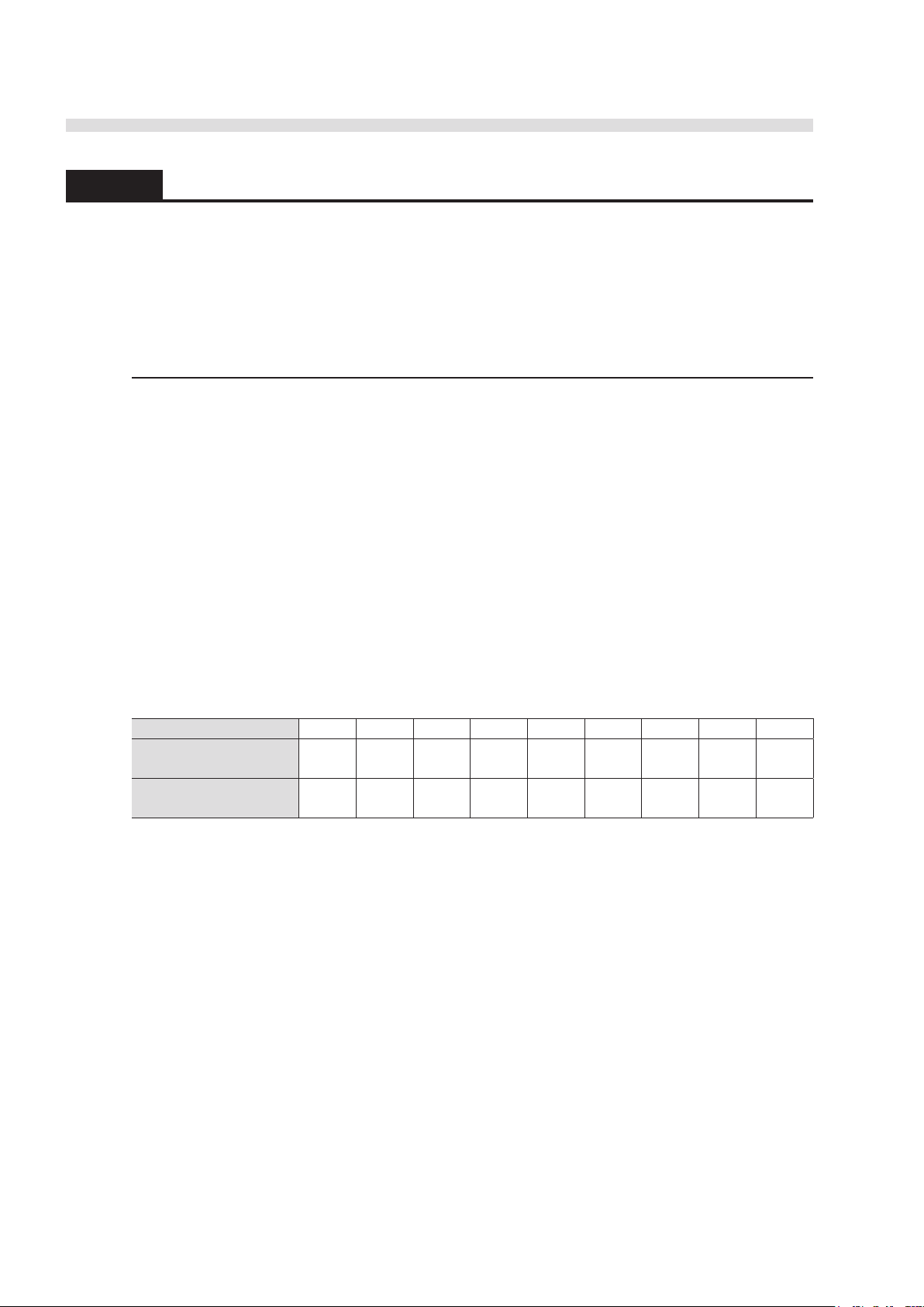
Wavelengths by measurement item
Measurement item GLU PRO BIL URO PH BLD KET NIT LEU
Measurement
wavelength (nm)
Reference
wavelength (nm)
635 635 565 565 635 635 565 565 565
760 760 760 760 760 – 760 760 760
Reflectivity is measured with the formula below.
R = (Tm • Cs) / (Ts • Cm)
R: Reflectivity
Tm: Amount of reflected light coming from reagent pad at measurement wavelength
Ts: Amount of reflected light coming from reagent pad at reference wavelength
Cm: Amount of reflected light coming from color correction pad at measurement
wavelength
Cs: Amount of reflected light coming from color correction pad at reference
wavelength
1-6
However, BLD is measured with only one wavelength and calculated with the formula below.
R = Tm / Cm
AX-4030
B
Page 18
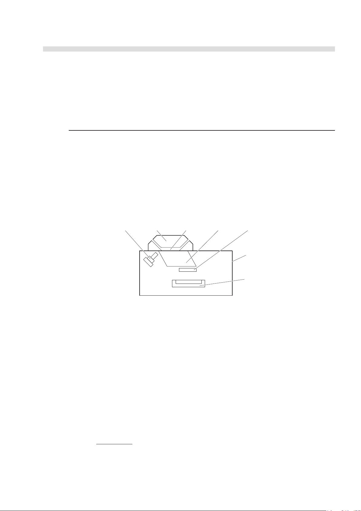
AUTION MAX AX-4030 OPERATING MANUAL
Light source (LED) Flow cell Sample route Prism Slit
Specific gravimeter unit
CCD image sensor
These reflectivities “R” are compared against calibration curves stored in the instrument and
output as measurement results. Also, temperature is corrected to eliminate changes caused by
environmental temperature.
Specific Gravity (S.G.) Measurement
Specific gravity of a urine sample is obtained by measuring the refraction of the sample using a
prism and subjecting results to a calculation formula (reflection refractometry). The light from an
LED passes through the prism and is reflected on the prism face contacting the sample. The light
reflected off the prism is collimated into a thin beam by passing through a slit and directed to a
detector (CCD image sensor). At this point, the refractive index at the interface between the prism
face and sample will change according to the specific gravity, therefore the position of the incident
light from the slit will change. The refractive index is obtained by detecting the position of the
incident light and, after correcting it for temperature effects, it is converted into a Brix value. The
specific gravity of the sample is then obtained using this Brix value and a conversion formula.
The Brix value is the sugar content of an aqueous solution measured at 20°C and represents the
strength of the solution as percentage by weight.
For example, the Brix value is 30% for a 30% sucrose solution (30 g of sucrose sugar and 70 g of
water in a 100 g solution).
Specific gravity is calculated as follows:
1. The specific gravity of the sample is calculated.
SGx´ = 1 + (4/900) * Brix value
(However, specific gravity is equal to 1,000 if the Brix value is below 0.)
2. Correction coefficients
a and b are calculated from the low and high specific gravity values
obtained from S.G. calibration.
a =
SGL – SGH
KL – KH
b = SGL – (a × KL)
F
AX-4030
1-7
Page 19
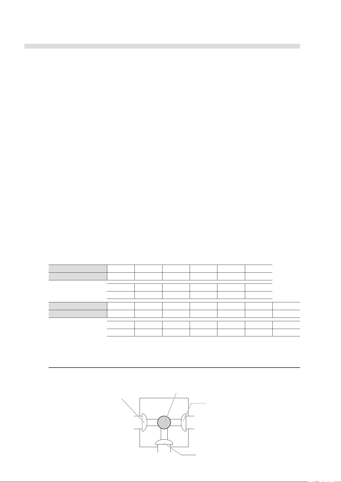
AUTION MAX AX-4030 OPERATING MANUAL
470 nm/525 nm/635 nm
multiple wavelength LED
Cylindrical cell (i.d. 1.8 mm)
Photodiode (transmitted light)
Photodiode (Scattered light)
3. The obtained specific gravity value of the sample is corrected using correction coefficients a and
b.
SGx = a × SGx´ + b
SGx: Sample’s specific gravity after calibration correction
SGx´: Sample’s specific gravity before calibration correction
SGH: Specific gravity reference of standard solution (high)
SGL: Specific gravity reference of standard solution (low)
KH: Specific gravity of standard solution (high)
KL: Specific gravity of standard solution (low)
Furthermore, high concentrations of glucose (GLU) and protein (PRO) will affect specific gravity.
Therefore, specific gravity is corrected using the concentrations of glucose and protein obtained
from test strip measurement.
SG = SGx – CGLU – CPRO
SG: Specific gravity after GLU and PRO correction
SGx: Specific gravity obtained from formula 3.
CGLU: Corrected GLU value
CPRO: Corrected PRO value
Correction values (Unit of concentration: mg/dL)
GLU concentration 0 10 30 50 70 100
Correction value 0.0000 0.0000 0.0001 0.0002 0.0003 0.0004
150 200 300 500 1000 OVER
0.0006 0.0008 0.0012 0.0020 0.0040 0.0040
PRO concentration 0 5 10 20 30 50 70
Correction value 0.0000 0.0000 0.0000 0.0001 0.0001 0.0002 0.0002
100 150 200 250 300 600 OVER
0.0003 0.0005 0.0006 0.0008 0.0009 0.0018 0.0018
1-8
Color-Tone Measurement
An internal turbidity/color measurement unit measures sample color using transmitted light.
AX-4030
A
Page 20
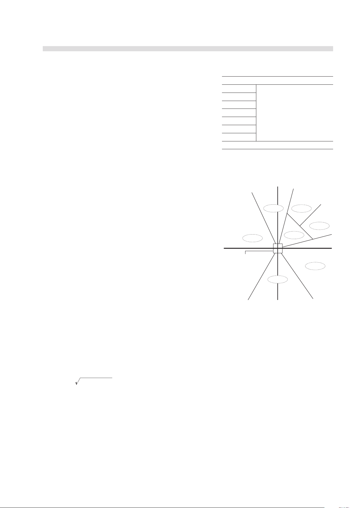
AUTION MAX AX-4030 OPERATING MANUAL
y
x
YELLOW
GREEN
BLUE
COLORLESS
VIOLET
RED
BROWN
ORANGE
In color-tone measurement, red (635 nm), green
(525 nm) and blue (470 nm) lights are irradiated on
the sample in the cylindrical tube and the hue and
contrast of the sample are obtained from the amount
of transmitted light.
The color is evaluated against 23 standard colors
consisting of light, normal and dark shades of yellow,
orange, brown, red, violet, blue and green (21 total),
plus colorless and other.
Hue is obtained from the areas in the coordinate
system at right. Coordinates are calculated as follows:
1. XYZ stimulus is obtained.
X = ( (a × R) + (b × G) + (c × B) ) ÷ 1000
Y = ( (d × R) + (e × G) + (f × B) ) ÷ 1000
Z = ( (g × G) + (h × B) ) ÷ 1000
Contrast and hue indications (23 colors)
COLORLESS
YELLOW LIGHT, normal and DARK
ORANGE
BROWN
RED
VIOLET
BLUE
GREEN
OTHER
are indicated for each color.
Example: LIGHT YELLOW,
YELLOW, and
DARK YELLOW
Color classification
R: Transmission intensity of 635 nm light
G: Transmission intensity of 525 nm light
B: Transmission intensity of 470 nm light
a to h: Correction coefficients
2. The x and y color coordinates are obtained from formula 1.
x = X ÷ (X + Y + Z)
y = Y ÷ (X + Y + Z)
3. The density is obtained from formula 2.
(x2 + y2)
1-9
A
AX-4030
Page 21
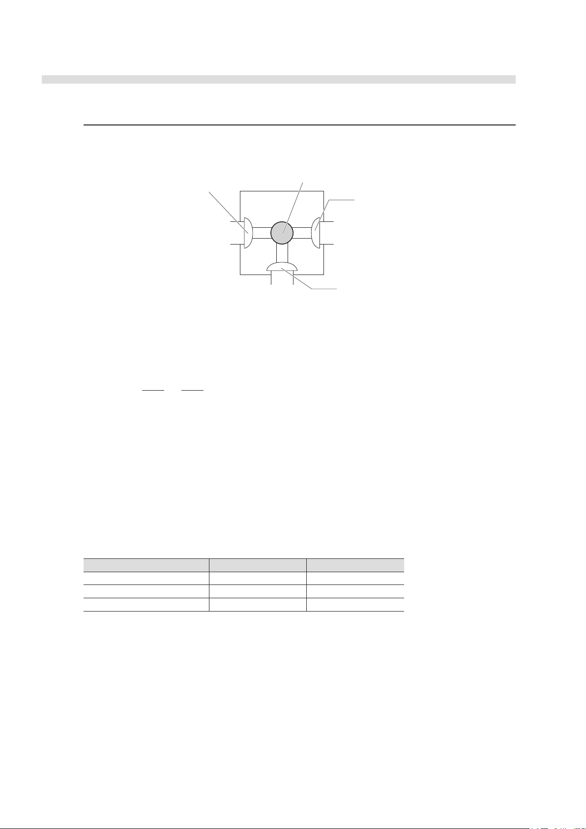
AUTION MAX AX-4030 OPERATING MANUAL
470 nm/525 nm/635 nm
multiple wavelength LED
Cylindrical cell (i.d. 1.8 mm)
Photodiode (transmitted light)
Photodiode (Scattered light)
Turbidity Measurement
An internal turbidity/color measurement unit measures sample turbidity using transmitted and
scattered lights.
Light of 635 nm is irradiated on the sample in the cylindrical cell and turbidity is calculated using
the formula below.
T =
T: Turbidity
Ss: Scattered light of sample
Ts: Transmitted light of sample
Sw: Scattered light of washing solution
Tw: Transmitted light of washing solution
K: Factory-set instrument coefficient
Turbidity is determined by the obtained T value.
T range Turbidity Output
T < (Level 1)
(Level 1) ≤ T < (Level 2) Turbid 1+
(Level 2) ≤ T Densely turbid 2+
* (Level 1) and (Level 2) are constants.
Ss
(
Ts
Sw
–
Tw
K
)
/
Clear –
1-10
AX-4030
A
Page 22
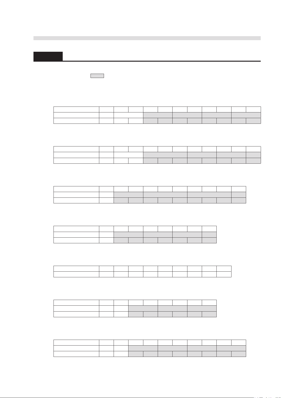
1.1.5 Rank Table
Measurement results are represented as qualitative and/or semi-quantitative values as listed below.
The shaded areas contain abnormal values, which are preceded by an abnormal mark (*) on
the displayed and printed reports.
GLU (glucose)
Rank 1 2 3 4 5 6 7 8 9 10 11
Qualitative – ± 1+ 2+ 3+ 4+
Semiquantitative (mg/dL)
PRO (protein)
Rank 1 2 3 4 5 6 7 8 9 10 11
Qualitative – ± 1+ 2+ 3+ 4+
Semiquantitative (mg/dL)
AUTION MAX AX-4030 OPERATING MANUAL
30 50 70 100 150 200 300 500 1000 OVER
10 20 30 50 70 100 200 300 600 OVER
BIL (bilirubin)
Rank 1 2 3 4 5 6 7 8 9 10
Qualitative – 1+ 2+ 3+ 4+
Semiquantitative (mg/dL)
0.5 1.0 2.0 3.0 4.0 6.0 8.0 10.0 OVER
URO (urobilinogen)
Rank 1 2 3 4 5 6 7 8
Qualitative
Semiquantitative (mg/dL)
NORMAL
1+ 2+ 3+ 4+
2 3 4 6 8 12 OVER
PH (pH)
Rank 1 2 3 4 5 6 7 8 9
Value 5.0 5.5 6.0 6.5 7.0 7.5 8.0 8.5 9.0
BLD (blood)
Rank 1 2 3 4 5 6 7 8
Qualitative – ± 1+ 2+ 3+
Semiquantitative (mg/dL)
0.03 0.06 0.1 0.2 0.5 1.0 OVER
AX-4030
KET (ketones)
Rank 1 2 3 4 5 6 7 8 9 10
Qualitative – ± 1+ 2+ 3+ 4+
Semiquantitative (mg/dL)
10 20 40 60 80 100 150 OVER
1-11
Page 23

AUTION MAX AX-4030 OPERATING MANUAL
NIT (nitrite)
Rank 1 2 3
Qualitative – 1+ 2+
LEU (leukocytes)
Rank 1 2 3 4 5
Qualitative –
Semiquantitative (Leu/μL) 25 75 250 500
1-12
AX-4030
Page 24
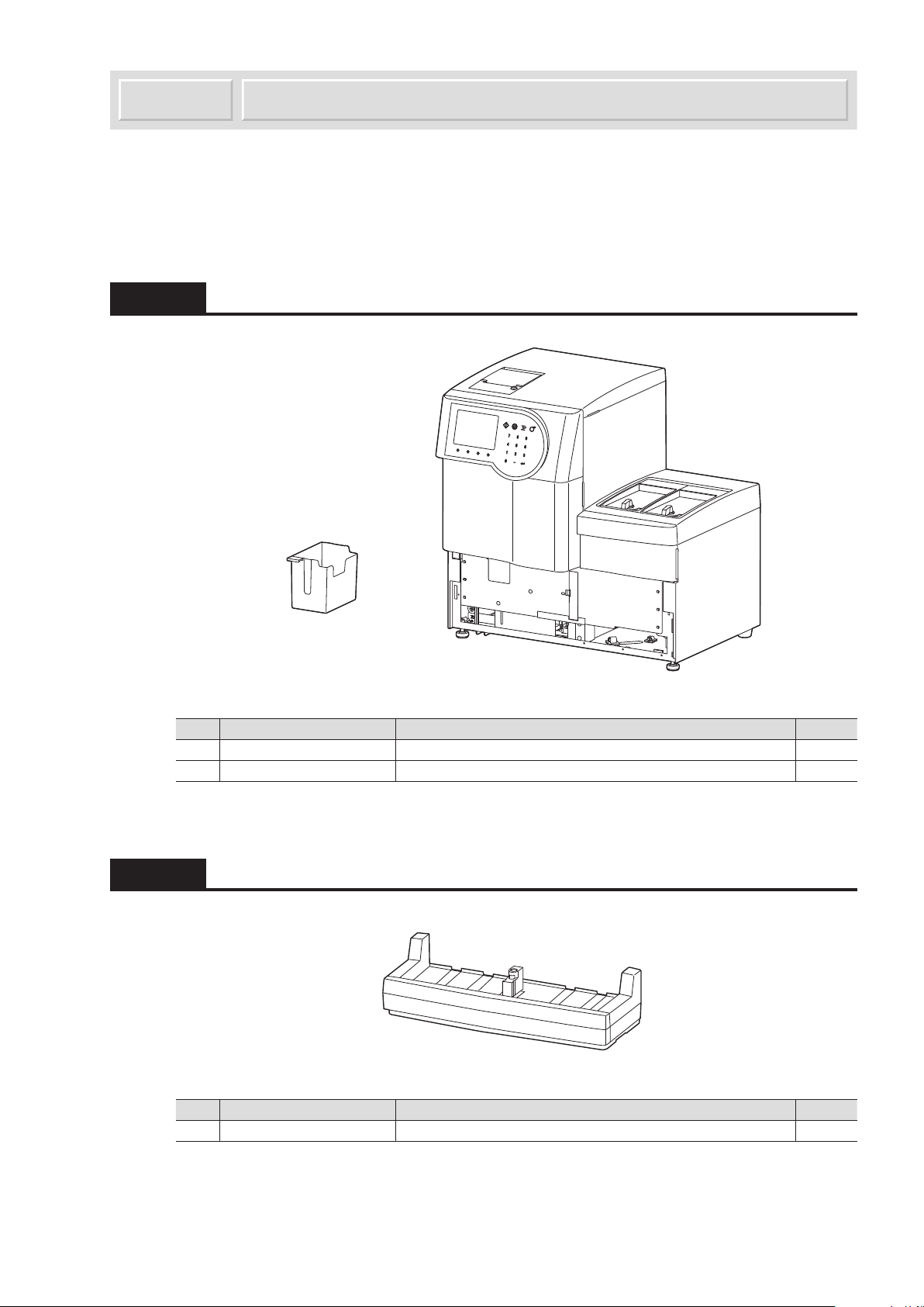
1. Instrument
2. Waste box
Sampler
Unpacking1.2
The instrument boxes in three cartons. Unpack the boxes and make sure you have all items listed in
this section. If anything is missing or damaged, contact your distributor.
1.2.1 Instrument
AUTION MAX AX-4030 OPERATING MANUAL
No. Item Description Qty.
1 Instrument AUTION MAX AX-4030 1
2 Waste box 1
1.2.2 Sampler
No. Item Description Qty.
1 Sampler Rack type 1
D
AX-4030
1-13
Page 25
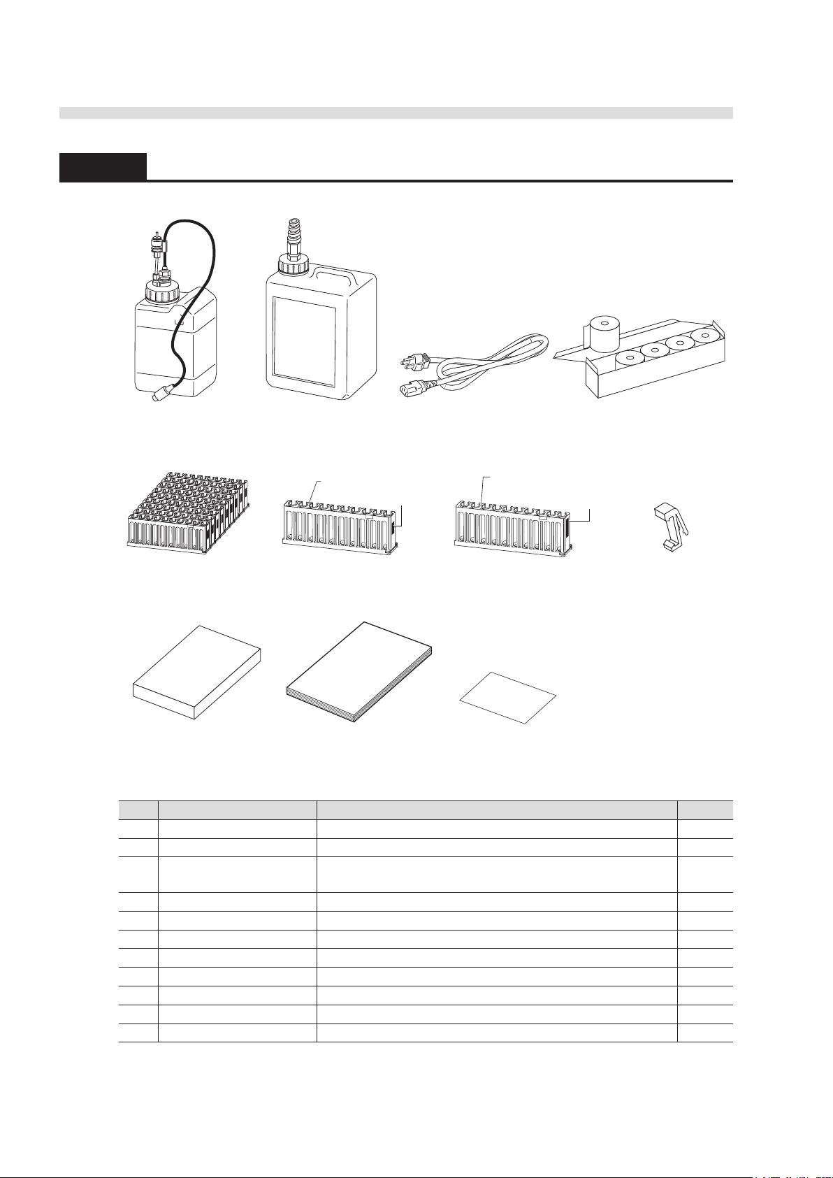
AUTION MAX AX-4030 OPERATING MANUAL
5. Rack set
9. Accessory case 10. Operating manual 11. Error and trouble list
6. Start rack 7. STAT and control rack 8. Adapter (gray)
Light blue adapter
Black label
Orange adapter × 7
Dark blue adapter × 3
Black label
2. Drain bottle 3. Power cord
4. Thermal printer paper
1. Washing solution bottle
1.2.3 Accessories
No. Items Descriptions Qty.
1 Washing solution bottle With a liquid sensor cord, 2 L 1
2 Drain bottle 3 L 1
3 Power cord The type of power cord supplied varies depending on the
country.
4 Thermal printer paper 58-mm width, 5 rolls 1
5 Rack set 10 item racks with rubber cushions 1
6 Start rack With rubber cushions and light blue adapters 1
7 STAT and control rack With rubber cushions, and orange and blue adapters 1
8 Adapters Gray colored 100
9 Accessory case See page 1-15. 1
10 Operating manual This manual 1
11 Error and trouble list 1
1-14
1
AX-4030
D
Page 26
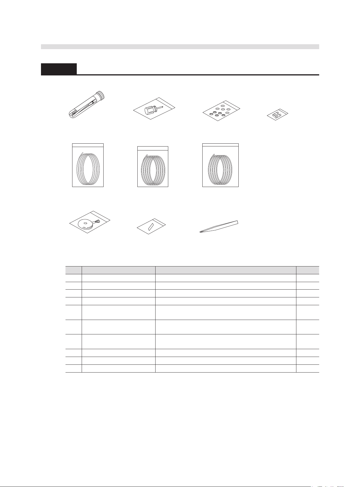
1.2.4 Accessory Case
1. Check strip set
5. Tygon tube 6. Silicon tube 7. Silicon tubes
8. Blower brush 10. Tweezers9. White plate
3. Filter set 4. Fuses
2. Phillips screwdriver
AUTION MAX AX-4030 OPERATING MANUAL
No. Items Descriptions Qty.
1 Check strip set White check strips × 2, Gray check strips × 2 1
2 Phillips screwdriver No.2, plastic insulated 1
3 Filter set Mesh filter, O-ring (5 pieces for each) 1
4 Fuses T5AE250V~ × 2 1
5 Tygon tube For washing solution bottle
6 Silicon tube For drain bottle
7 Silicon tubes For drain pinch valves
8 Blower brush 1
9 White plate 1
10 Tweezers L125 1
1
1/16” (i.d.) × 3/16” (o.d.), 2 m × 1
1
3 mm (i.d.) × 6 mm (o.d.), 4 m × 1
1
2 mm (i.d.) × 4 mm (o.d.), 100 mm × 2
H
AX-4030
1-15
Page 27
AUTION MAX AX-4030 OPERATING MANUAL
1
2
3
4
5
6
7
8
9
10
15
11
13
14
12
With the side cover open
16
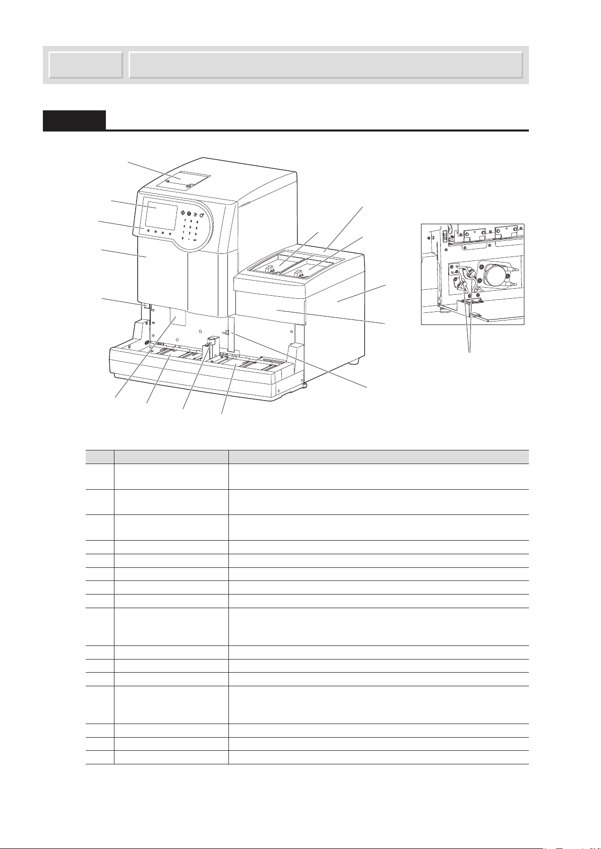
Components1.3
1.3.1 Front View
No. Components Descriptions
1 Standby switch Use this switch to turn on and off the instrument for daily use. The
switch lamp illuminates green while the power is on.
2 Front cover This protects the nozzle drive unit and prevents users from accidentally
touching the nozzle.
3 Operator panel There are operation keys for starting measurement and entering
numeric values. See
4 Display You can view results and check status information here.
5 Built-in printer This thermal printer prints results and parameter settings.
6 Feeder protective cover This cover protects two feeders.
7 Feeder cover 1 This cover has a locking lever to open and close feeder 1.
8 Feeder cover 2 This cover has a locking lever to open and close feeder 2.
9 Side cover The pumps for aspirating samples, for staining samples on test strips,
and for flushing the washing solution are located inside. The trap bottle
is also attached here.
10 Maintenance cover Open this cover to clean inside the instrument.
11 Loading side Place sample racks with samples loaded here.
12 STAT port Load a sample for port STAT measurement here.
13 Unloading side The sample racks are discharged here after sample aspiration. If the
14 White plate cover Open this cover to replace the white plate.
15 Built-in barcode reader The barcode reader reads barcodes labeled on sample tubes.
16 Drain pinch valves These valves control drainage flow.
instrument has been set for loop transportation, you can load 5 more
sample racks to be measured here.
“1.7 Basic Operations” on page 1-40.
1-16
AX-4030
D
Page 28
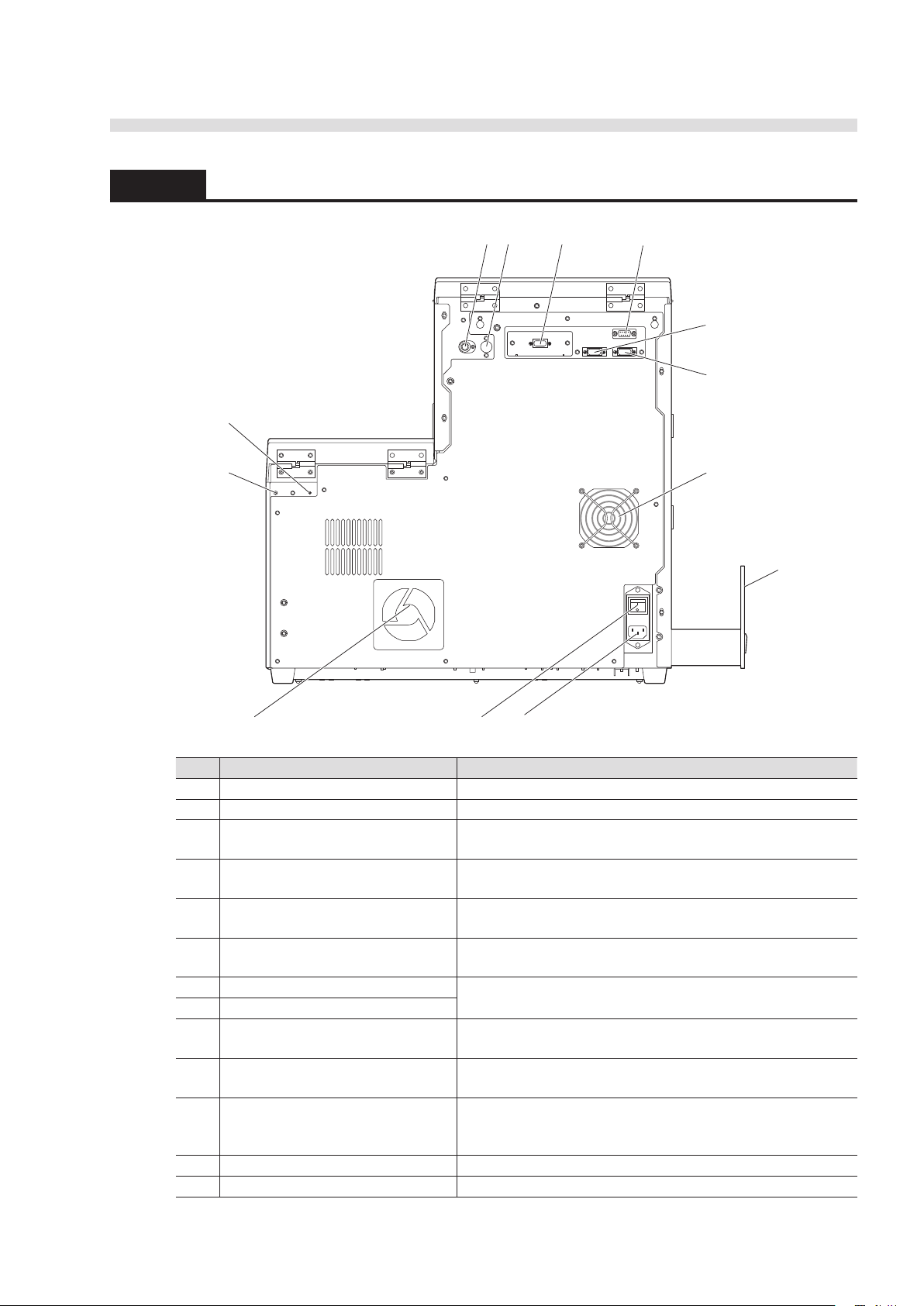
1.3.2 Rear View
W
H P 1 2
E
S
D
9
1110
8
12
13
1
4 5
6
7
3
2
AUTION MAX AX-4030 OPERATING MANUAL
No. Components Descriptions
1 Drain joint (D) Connect the tube from the drain bottle here.
2 Washing solution joint (W) Connect the tube from the washing solution bottle here.
3 Washing solution sensor terminal
(S)
4 Hand-held barcode reader terminal
(H)
Connect the liquid sensor cord of the washing solution bottle
here.
Connect the optional hand-held barcode reader here.
5 Data output terminal (P)* Connect the communication cable from an RS-232C port of
6 Data output terminal (E) Connect the communication cable from an RS-232C port of
an external device here.
the AX-4030-exclusive device here.
7 START terminal (1) Use these terminals to attach the extended sampler or joining
8 STOCK terminal (2)
9 Cooling fan The fan exhausts heated air to keep the inside of the
unit A.
instrument cool.
10 Cooling fan The fan draws in air from outside to cool the inside of the
instrument.
11 Main power switch Press this switch to turn on or off the main power supply.
Keep this switch on for daily use, and turn it off when cleaning
specific components or during long-term disuse.
12 Power input terminal Connect the power cord which came with the instrument here.
13 Waste box tray Attach the waste box here to collect used test strips.
* This terminal can be replaced with the Ethernet terminal (optional Ethernet board) to connect the instrument to a LAN.
For more information, contact your distributor.
AX-4030
1-17
Page 29
AUTION MAX AX-4030 OPERATING MANUAL
Installation1.4
1.4.1 Precautions in Instrument Installation
Before installation of the instrument, read the following notes and always take proper safety
precautions.
Install the instrument under the supervision of a serviceperson. It is
dangerous to handle the instrument with the covers open. High voltage
parts are located inside. Contact could be dangerous.
■ The instrument weighs about 37 kg and the sampler about 4 kg. Determine a
location for the instrument and assemble it in that location. Do NOT carry the
instrument with the sampler attached. Separate the two units before moving. For
safety reasons, always transport and assemble the instrument with the help of at
least one other person. Hold the bottom of the instrument with both hands when
carrying it.
■ During installation, be careful not to pinch your hands under the instrument.
■ Install the instrument at least 20 cm away from walls. Inadequate clearance
between the instrument and walls may cause overheating of the instrument
or undesirable load on cable connections, thus resulting in fire or incorrect
measurement results.
■ Ensure at least 10 cm clearance between walls and the left panel (viewed from
the front) for users to be able to draw the waste box and dispose of the used
test strips. Insufficient distances may block the waste box. Also, users will have
trouble trying to turn off the main power switch and disconnect connectors in the
event of errors or trouble.
■ Install the instrument where temperature and humidity can be maintained in the
following ranges:
Temperature: 10°C - 30°C
Humidity: 20% - 80%
Installation in the measurement environment outside these ranges may result in
incorrect measurement results.
■ Install the instrument on a level, vibration-free sturdy platform. Operation of
the instrument in an unstable place may cause trouble or malfunction of the
instrument resulting in personal injury. DO NOT install the instrument where it
may fall off or topple over.
1-18
■ Do not install the instrument near places that store chemicals or near equipment
that generates corrosive gas or electrical noise. Chemicals, corrosive gases and
electrical noise may cause fire or damage to the instrument and consequently
lead to personal injury, or may otherwise cause incorrect measurement results.
AX-4030
Page 30

AUTION MAX AX-4030 OPERATING MANUAL
■ Install the instrument in a place not exposed to direct sunlight, condensation
or wind. These factors may cause incorrect measurement results, as well as
deformation of or damage to the instrument.
■ Apply the correct voltage (100 to 240 V AC) and frequency (50/60 Hz) to the
instrument. The wrong voltage and frequency may result in fire or damage to the
instrument and consequently lead to personal injury.
■ Use the power cord that came with the instrument for the electrical connection to
avoid electric shock and fire.
■ Connect the instrument’s power cord directly to a single outlet, without using an
extension cord or power tap. The maximum power supply for the instrument is
150 VA.
■ Use the specified RS-232C cross cable to connect an external device to the 9-pin
data output terminal of the instrument, to avoid electric shock and fire. For more
information, contact your distributor.
■ Use the specified Ethernet cable to connect an external device to the Ethernet
terminal that is provided when the optional Ethernet board is installed in the
instrument. Use of other cables may cause electric shock or fire. For more
information, contact your distributor.
■ The START (1) and STOCK (2) terminals are used to connect optional joining
unit A or an expansion sampler. Connecting to other devices may cause damage
to the instrument. For the installation of these optional parts or precautions
on operating them, contact your distributor. Install optional parts under the
supervision of a serviceperson. Confirm operating precautions with the
serviceperson ahead of use.
■ DO NOT disassemble the instrument unless required for installation. DO NOT
modify the instrument. Disassembly and modification of the instrument may
result in exposure to pathogenic microbes or cause fire or damage to the
instrument and consequently lead to personal injury.
AX-4030
■ If you need to disassemble the instrument after use, wear protective gloves to
prevent exposure to pathogenic microbes.
1-19
Page 31
AUTION MAX AX-4030 OPERATING MANUAL
Waste box tray (left panel)
Front cover
Retainer
Screw
Screws
2
3
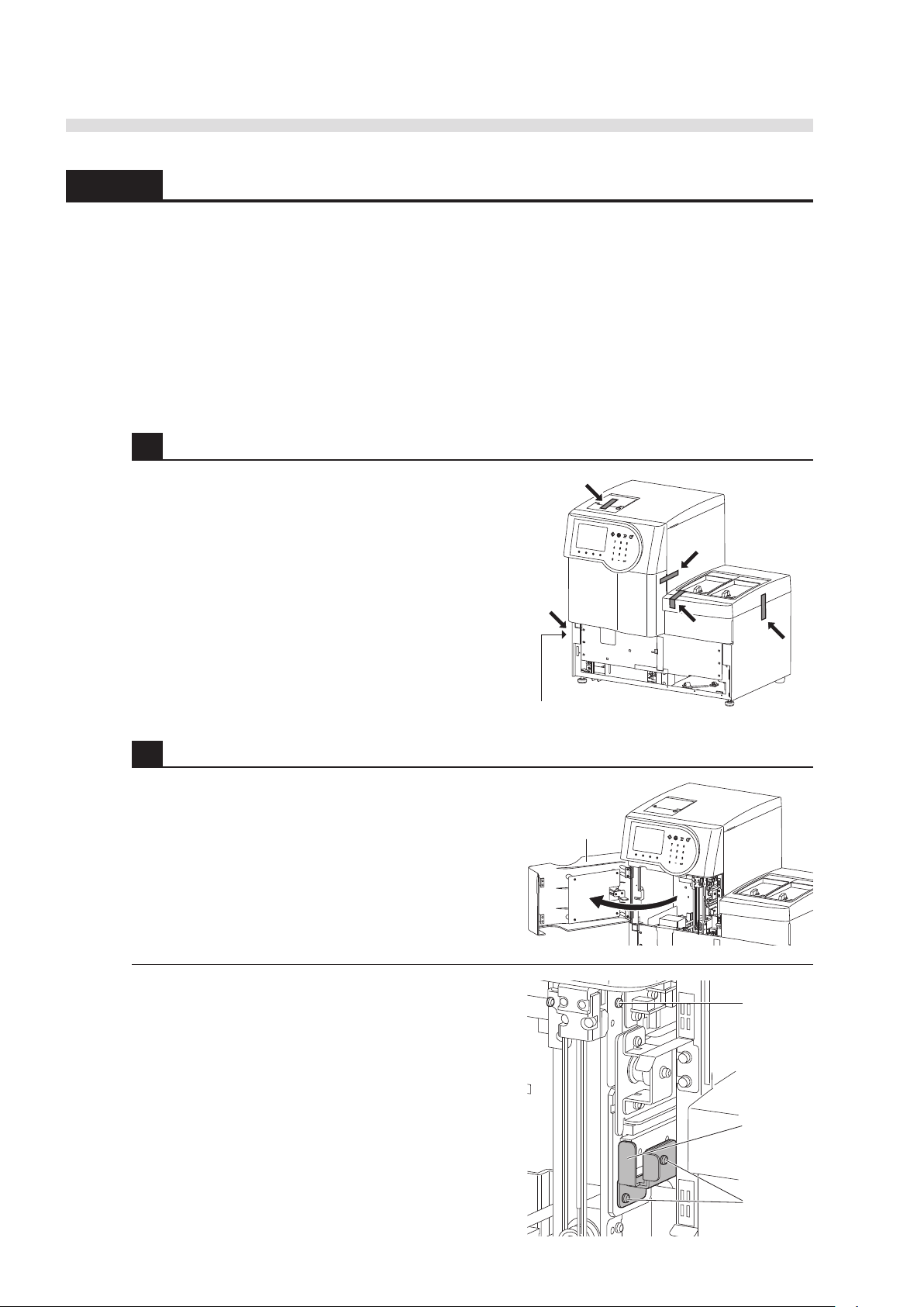
1.4.2 Unlocking the Instrument
To prevent the instrument from being damaged in transport, various parts are anchored before
shipping from the factory. Remove these retainers before installing the instrument. Also, before
doing anything, read “1.4.1 Precautions” on page 1-18.
Prepare: Phillips screwdriver
REFERENCE: Keep your removed screws in the accessory case. These screws will be needed
the next time the instrument is moved.
1 Remove the anchoring tape.
1 Remove the anchoring tape at the locations shown
in the right figure.
• Also, remove the tape from the waste box tray on
the left panel.
2 Unlock the nozzle drive section.
1 Open the front cover.
2 Loosen the screw that locks the nozzle drive using a
Phillips screwdriver, and remove it.
3 Loosen the two screws on the retainer of the nozzle
drive with a Phillips screwdriver, and remove the
retainer.
NOTE: Take care not to drop the screws inside the
instrument.
1-20
4 Close the front cover.
AX-4030
D
Page 32
AUTION MAX AX-4030 OPERATING MANUAL
Feeder protective cover
Feeder
covers
Side cover
Maintenance cover
3
2
4
Feeder unit
Anchoring
tape
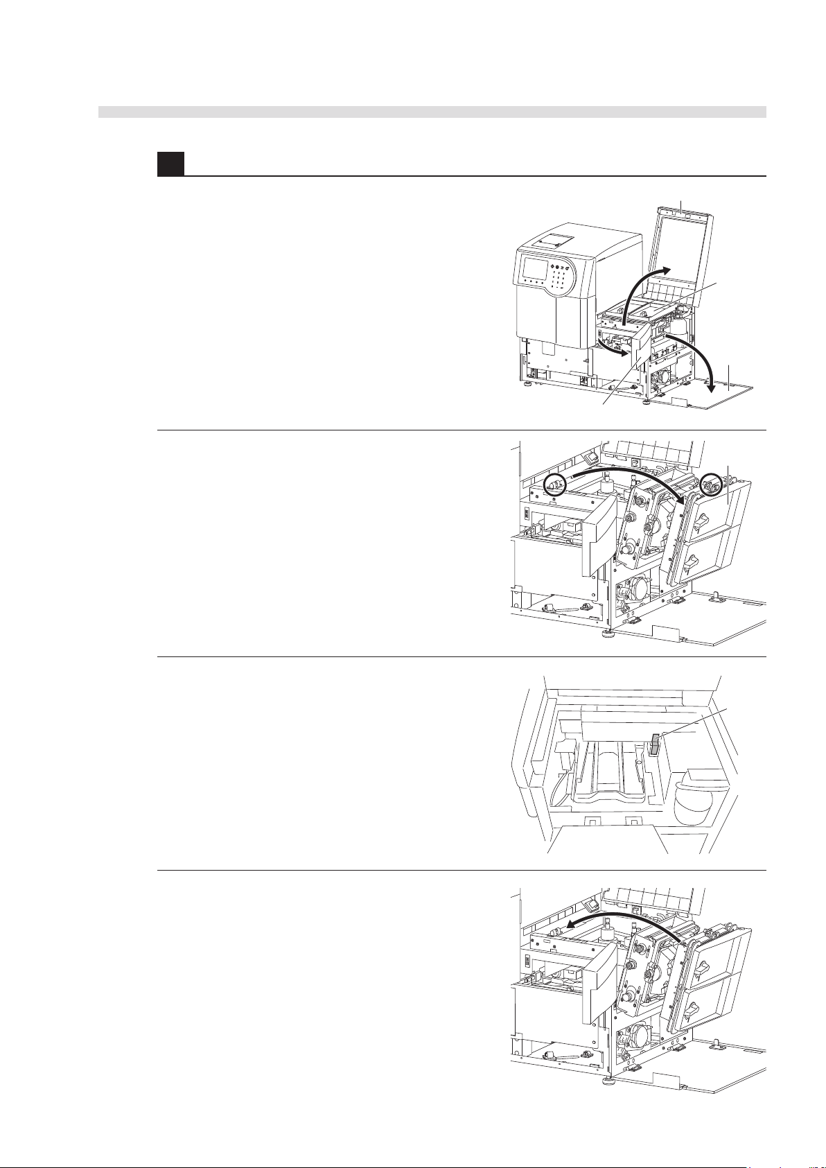
3 Remove the anchoring tape from the identification section.
1 Make sure both feeder covers are locked.
2 Open the maintenance cover.
3 Open the feeder protective cover.
• The cover stops at a 120° angle.
• This cover can be removed from the instrument by
unhooking the hinge.
4 Open the side cover.
5 Tilt the feeder unit to the right.
• The feeder unit is locked with the latch shown with
the circles in the figure. So, first you need to pull
the whole feeder unit to the right with a little force
to open the latch.
NOTE: Do not apply excessive pressure to the
feeder unit when in the tilted position, as this may
cause damage to the instrument.
6 Remove the anchoring tape.
AX-4030
7 Stand the feeder unit straight up.
• Once the feeder is standing up straight, press the
feeder downward until the latch clicks and the unit
locks in place.
1-21
Page 33
AUTION MAX AX-4030 OPERATING MANUAL
Feeder protective cover
(a)
(b)
(c)
Side cover
Maintenance cover
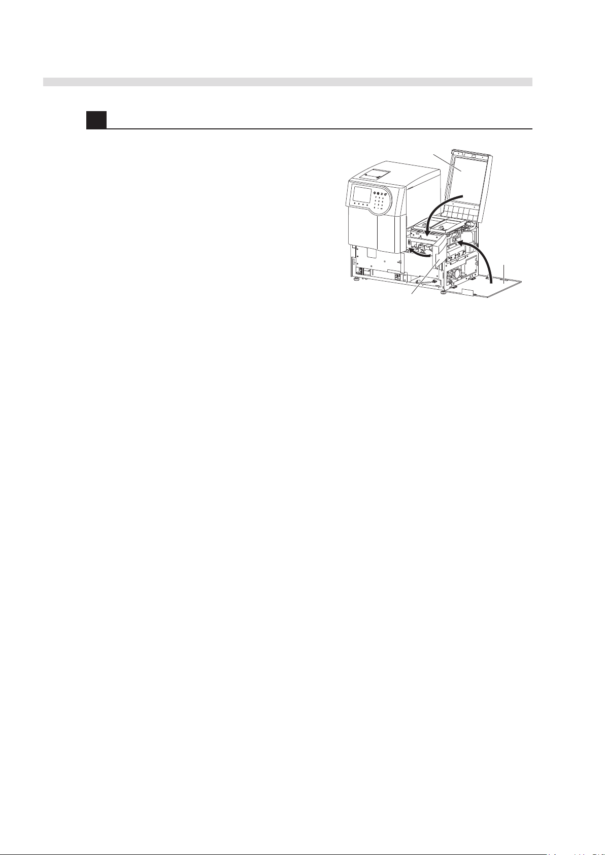
4 Close the covers.
1 Close the covers in the order of the side cover (a),
feeder protective cover (b), and maintenance cover
(c).
1-22
AX-4030
Page 34
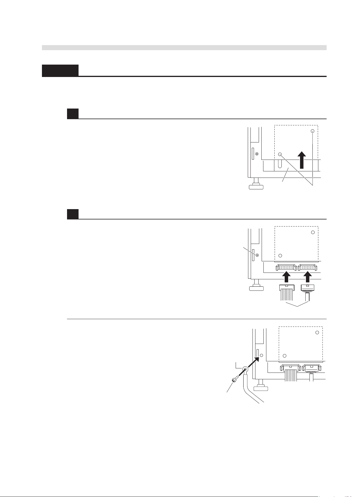
1.4.3 Attaching the Sampler
Screw holes
Splash guard
Sampler connectors
Earth
anchoring
screw
Earth
Earth
anchoring screw
Prepare: Sampler, and Phillips screwdriver
1 Open the splash guard.
1 Insert the tip of a Phillips screwdriver in the screw
holes on the splash guard to loosen the two screws
inside.
2 Slide the cover upward.
3 Temporarily tighten one of the screws using the
screwdriver to prevent the cover from dropping.
AUTION MAX AX-4030 OPERATING MANUAL
2 Connect the sampler cables to the instrument.
1 Place the sampler in front of the instrument.
2 Connect the two cables from the sampler to the
connectors on the lower part of the front panel.
3 Lock the connectors to avoid disconnection.
4 Loosen the earth anchoring screw from the
instrument with the Phillips screwdriver, and
remove it.
5 Fit the earth anchoring screw through the eye of the
sampler’s earth line and reattach the screw in its
original position.
AX-4030
1-23
Page 35
AUTION MAX AX-4030 OPERATING MANUAL
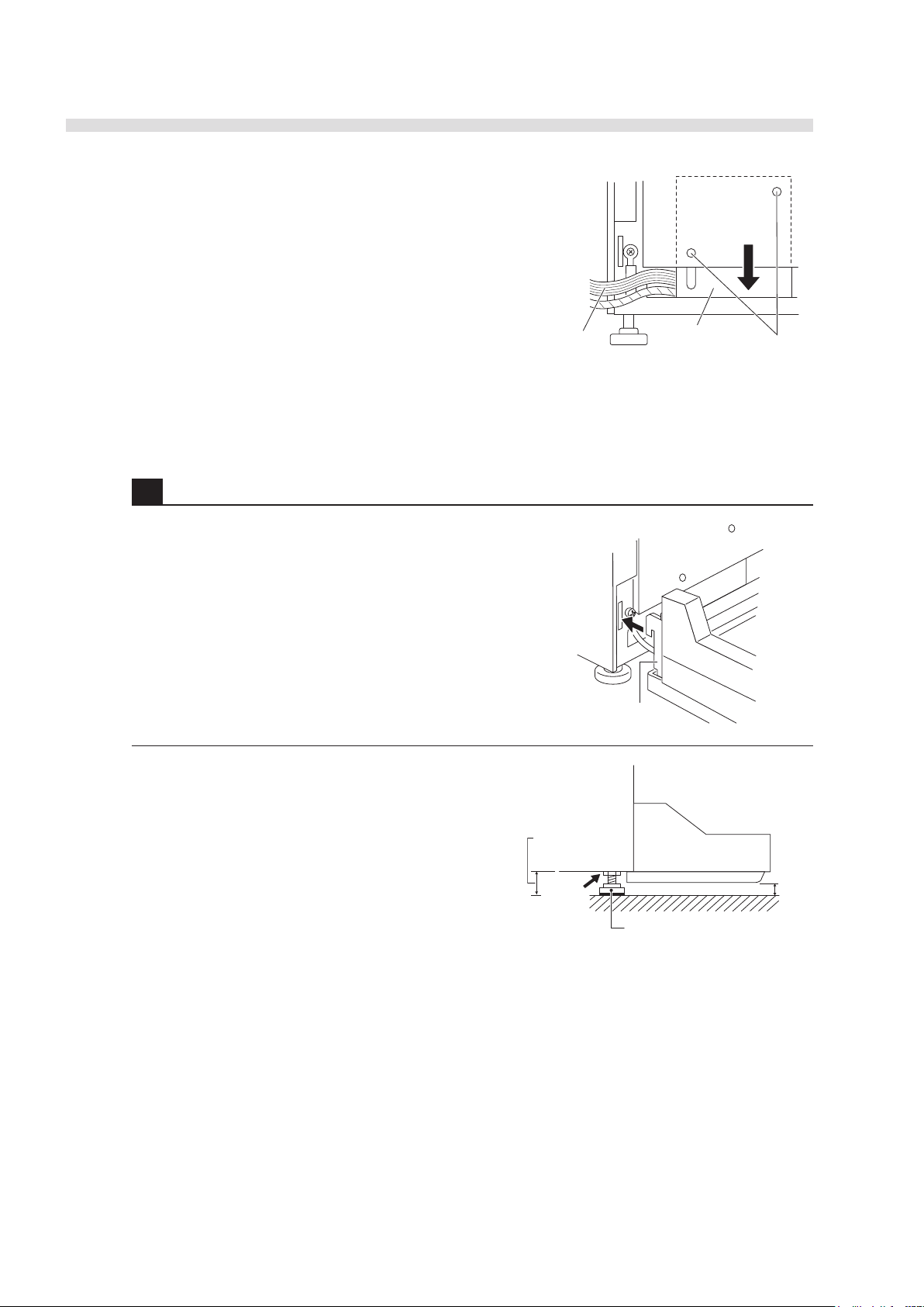
Screw holes
Splash guard
Cables
Hook
Instrument Sampler
5 mm
About 20 mm
Turn here to adjust height.
Loosen
this nut.
6 Feed the sampler cables through the left side of the
instrument.
7 Loosen the temporarily-tightened screw using a
Phillips screwdriver, and slide the splash guard
down.
NOTE: Make sure the cables do not get caught in
the splash guard.
8 Tighten the two screws using a Phillips screwdriver to secure the splash guard.
3 Attach the sampler to the instrument.
1 Fit the hooks on both sides of the sampler into the
holes on the instrument.
• Be careful not to pinch the cables and earth line.
2 Loosen the locking nut on the instrument legs close
to the sampler.
3 Turn the adjuster feet until the sampler rises an even
5 mm off the countertop.
• Check that the instrument has a clearance of about
20 mm from the countertop.
4 Tighten the locking nuts to lock the adjuster feet in place.
1-24
AX-4030
Page 36
AUTION MAX AX-4030 OPERATING MANUAL
Screw head of
the auxiliary legs
Countertop
Rubber
cap
Auxiliary legs
Screw head of
the auxiliary leg
STAT port viewed from above
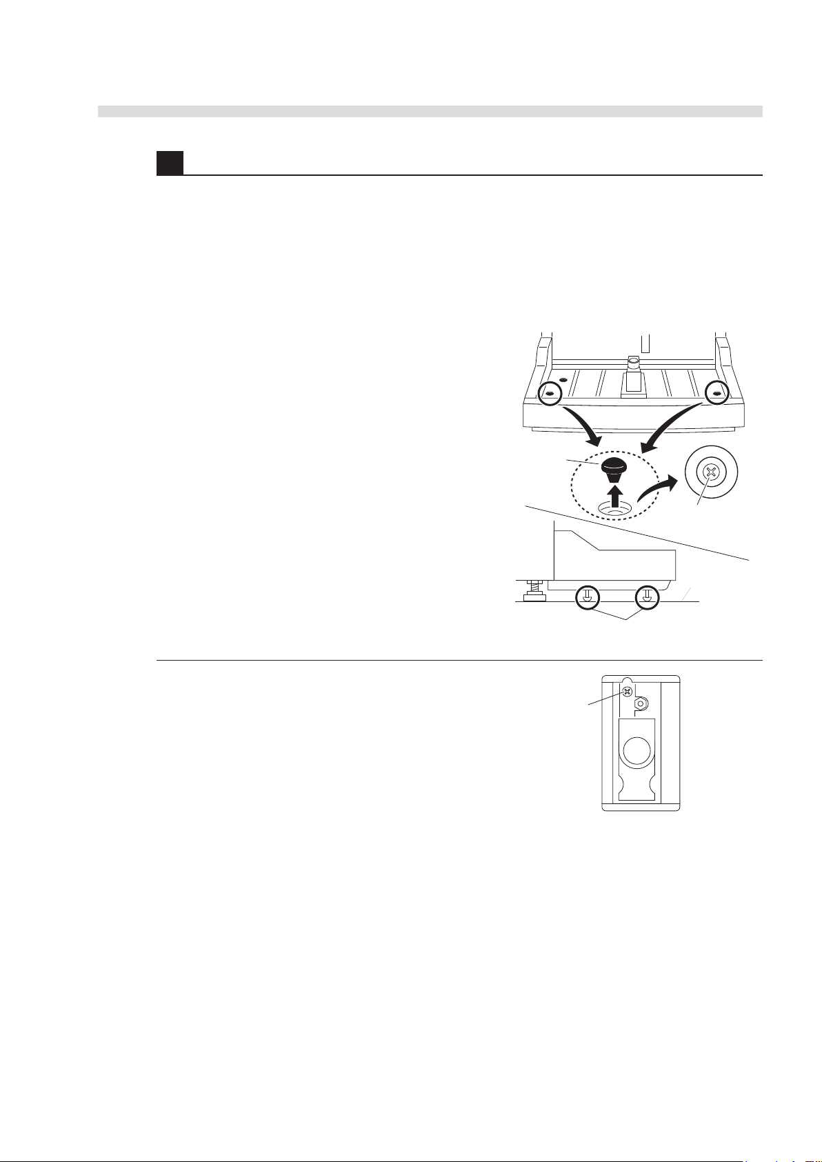
4 Adjust the auxiliary legs of the sampler.
NOTE: Lower the auxiliary legs of the sampler until they contact the countertop. Unless the
sampler is stable, it can deform under its own weight and the samples and the nozzle can be
damaged.
NOTE: The sampler has one auxiliary leg on each the right and left side of the bottom panel
and another one below the STAT port. Lower all three legs to the countertop. The sampler is
unstable on just one or two auxiliary legs.
1 Remove the two rubber caps from the sampler.
• You can see the screw heads of the auxiliary legs.
2 Turn the auxiliary leg screws clockwise with a
Phillips screwdriver until the auxiliary legs contact
the countertop.
NOTE: Excessively turning the auxiliary legs will
cause the sampler to rise. Lower the auxiliary legs
until they just contact the countertop.
3 Reattach the rubber caps.
4 Open the front cover.
5 Locate the screw head of the auxiliary leg at the
back of the STAT port.
6 Turn the screw until the auxiliary leg below the
STAT port contacts the countertop.
7 Close the front cover.
AX-4030
1-25
Page 37
AUTION MAX AX-4030 OPERATING MANUAL
Concentrated washing
solution 3
Purified water
1800 mL
200 mL
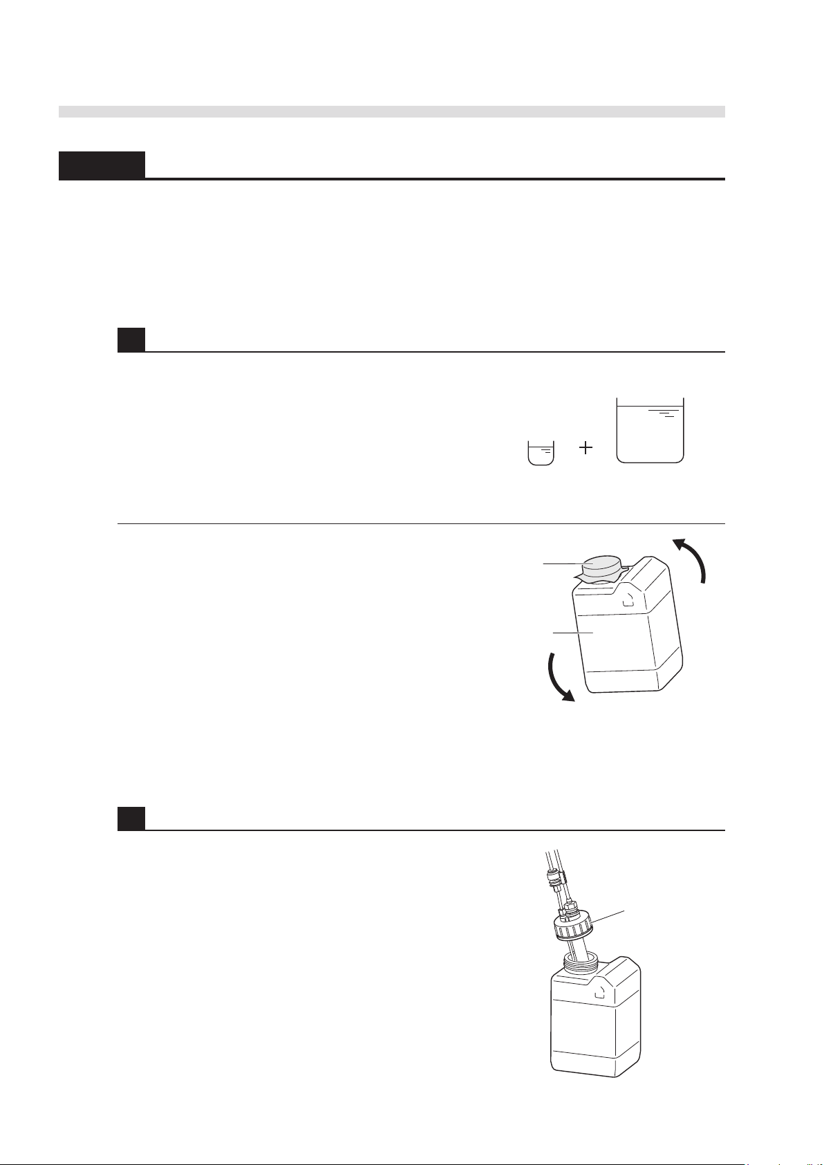
Example: To prepare 2000 mL of ten-fold
diluted washing solution
Sealing film
Washing
solution bottle
Bottle cap
1.4.4 Installing the Washing Solution Bottle
Prepare: Concentrated washing solution 3 (for AUTION MAX), purified water,
washing solution bottle, sealing film, and Tygon tube
REFERENCE: Purchase the concentrated washing solution 3, which is not supplied with the
instrument.
1 Prepare the washing solution.
1 Dilute concentrated washing solution 3 with
purified water.
NOTE: Check the correct dilution rate on the bottle
label of the concentrated washing solution 3.
2 Uncap the washing solution bottle.
3 Pour the diluted washing solution into the washing
solution bottle.
4 Seal the bottle with a piece of sealing film.
5 While holding the film in your hand, gently invert
the bottle so as not to froth the solution.
NOTE: Keep foreign matter out of the bottle and solution as this may cause the filter in the flow
line to clog.
2 Install the washing solution bottle.
1 Remove the sealing film from the bottle, and attach
the bottle cap.
1-26
AX-4030
Page 38
AUTION MAX AX-4030 OPERATING MANUAL
WD
HS
Liquid sensor cord
Washing solution joint
Washing solution sensor terminal
Tygon tube
3
1
4
Washing solution bottle
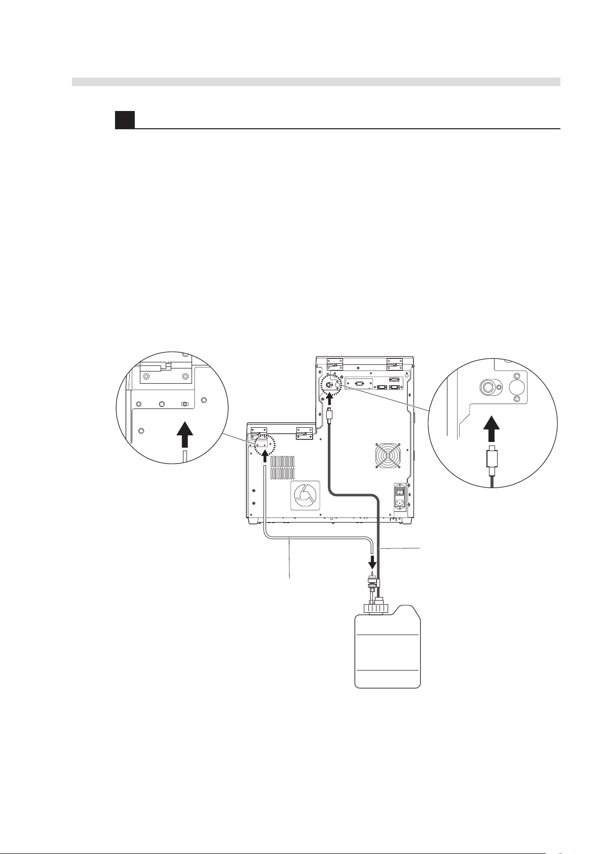
3 Connect the sensor cord and tube.
1 Connect the liquid sensor cord from the bottle cap to the washing solution sensor terminal “S” on
the rear panel.
2 Cut the Tygon tube to an appropriate length (max. 1 m).
NOTE: Use of a longer tube may interfere with solution filling. Keep the remaining tube in the
accessory case for replacement.
3 Fit one end of the Tygon tube over the washing solution joint “W” on the rear panel.
4 Fit the other end of the tube over the washing solution nozzle of the bottle cap.
NOTE: Care should be taken not to tear the tube by forcing it.
AX-4030
1-27
Page 39
AUTION MAX AX-4030 OPERATING MANUAL
Drain bottle
Silicon tube
Joint
Cap
5 cm
WD
Drain bottle
Silicon tube
Drain joint
1.4.5 Installing the Drain Bottle
Set the drain bottle at the same or a lower height than the surface that the
instrument sits on. If higher than the instrument base, liquid waste may
not drain properly and consequently leak. Contacting liquid waste with
unprotected hands may expose you to pathogenic microbes.
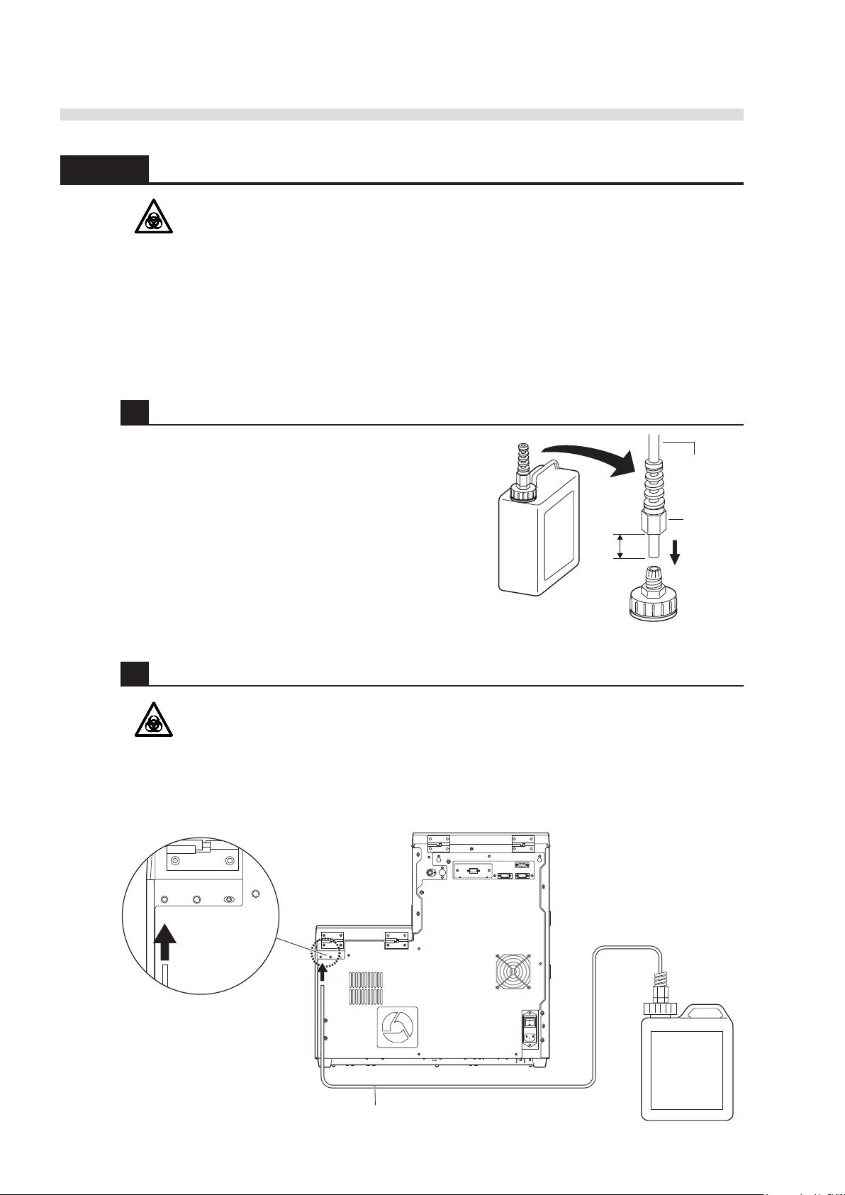
Urine samples and solution are discharged into the drain bottle. Place the bottle on a flat, level surface.
Prepare: Drain bottle and silicon tube [3 mm (i.d.) × 6 mm (o.d.), 4 m]
1 Connect the tube to the drain bottle.
1 Cut the silicon tube to an appropriate length.
2 Remove the joint from the drain bottle. Insert one
end of the silicon tube into the joint until the tube
extends about 5 cm from the joint.
3 Reattach the joint to the bottle cap, and tighten it
securely.
2 Connect the tube to the instrument.
Do not bend or pinch the silicon tube of the drain bottle. Also, keep
objects off of the tube. If liquid waste clogs inside the tube, the tube may
disconnect from the instrument and spill contained liquid. Contacting liquid
waste with unprotected hands may expose you to pathogenic microbes.
1 Fit the other end of the tube over the drain joint “D” on the rear panel.
1-28
AX-4030
Page 40
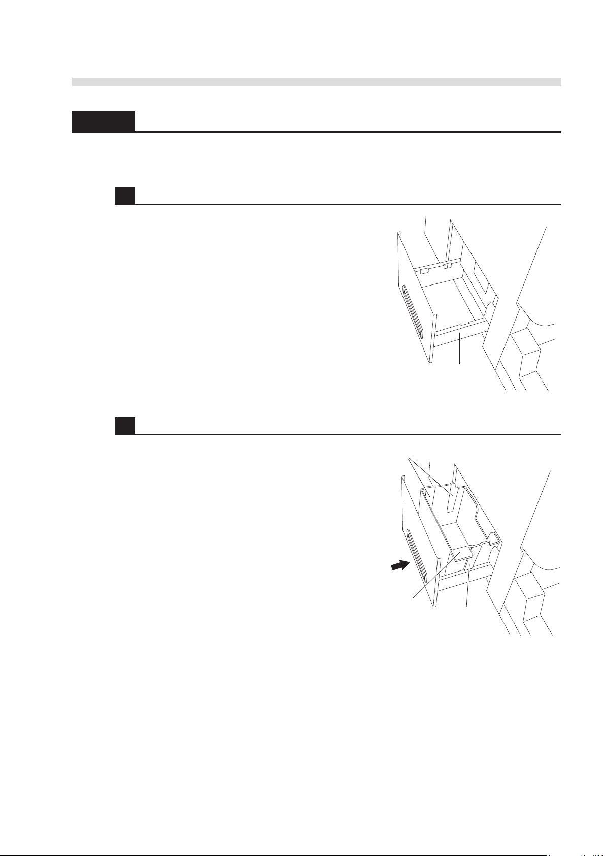
1.4.6 Installing the Waste Box
Waste box tray
One guide
Tab
Two guides
Install the waste box for collecting used test strips.
1 Pull out the waste box tray.
1 Pull out the waste box tray from the left panel of the
instrument.
AUTION MAX AX-4030 OPERATING MANUAL
2 Install the waste box.
1 Hold the waste box tab facing forward, and place
the box on the waste box tray.
• Ensure the waste box guides fit the concaves inside
the tray.
2 Store the waste box tray in the instrument.
• If the waste box is correctly set in the tray, it is held
steadily by the magnets.
• If the waste box gets caught halfway, it is set
incorrectly.
NOTE: Ensure the waste box correctly fits into the
tray before pushing it in. Incorrect installation may
cause used test strips to be scattered around
inside the instrument or to clog the test strip path.
AX-4030
1-29
Page 41
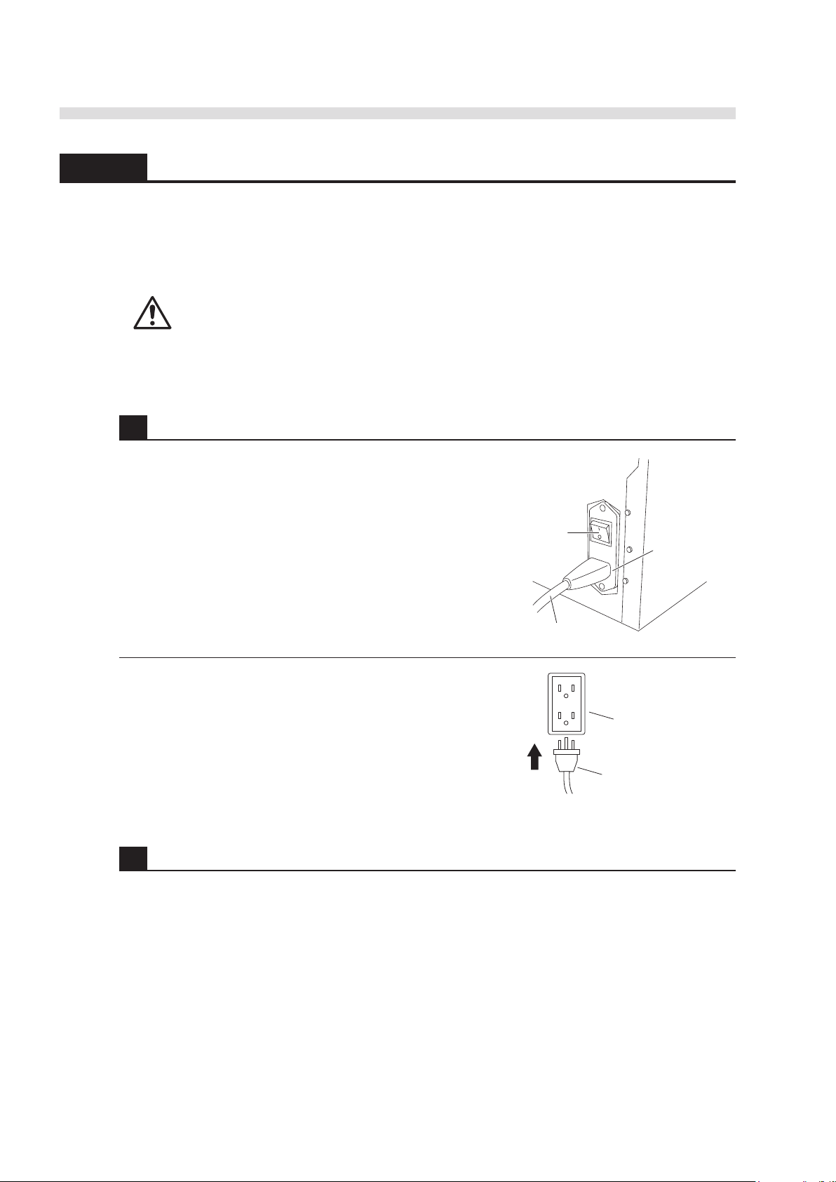
AUTION MAX AX-4030 OPERATING MANUAL
Power cord
Power input
terminal
Main power switch
Power cord
Receptacle
1.4.7 Connecting the Power Cord and External Devices
Connect the instrument to a receptacle using the supplied power cord, and also to an external
device as needed.
Prepare: Power cord and, if necessary, communication cable for the external device
Use the specified RS-232C cross cable or Ethernet cable to connect an
external device to the instrument. Connections using cables other than
these can cause electric shock and fire. For more information, contact your
distributor.
1 Connect the power cord.
1 Ensure the main power switch is in the off position.
• The main power switch should be depressed to the
(off) side.
°
2 Insert the female connector of the power cord into
the power input terminal on the rear panel.
3 Insert the male connector of the power cord into a
receptacle.
REFERENCE: The type of power cord supplied
varies depending on the country.
2 Connect an external device (if necessary).
1-30
NOTE: Use the specified RS-232C cross cable or Ethernet cable to connect an external device
to the instrument.
1 Connect one end of the communication cable to a data output terminal on the rear panel.
2 When using an RS-232C cable, tighten the safety screws to secure it.
3 For the connection of the other end of the cable, see the manual of the external device.
REFERENCE: The external output capability is disabled by default. To have the instrument
communicate with an external device, change the appropriate parameter setting. See “3.4.3
Enabling/Disabling the External Output” on page 3-20.
AX-4030
Page 42
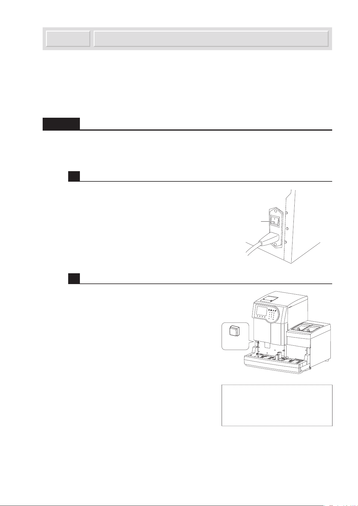
AUTION MAX AX-4030 OPERATING MANUAL
Main power switch
Standby
switch
Please wait...
AX-4030 V1.00
Starting Up1.5
This section describes what you should do next after completing installation; it includes turning on
the power and setting up the printer and system clock. How to turn off the power is also explained
at the end of this section.
1.5.1 Turning On the Power for the First Time
Use the following procedure to turn on the instrument for the first time after installation. It will take
about 2 minutes for the instrument to complete warm-up.
1 Turn on the main power switch.
1 Press the I (on) side of the main power switch on
the rear panel.
2 Turn on the standby switch.
1 Press the standby switch on the left side of the front
panel.
• The standby switch will light green.
• The message “Please wait...” will appear for a
maximum of 20 seconds, followed by the product
name and program version for about 2 seconds.
NOTE: If the initial memory check detects a problem, the instrument will inform you of it by
indicating an appropriate warning (W), error (E), or trouble (T) code before displaying the
program version. For more information, see Chapter 5, “Troubleshooting”.
G
AX-4030
1-31
Page 43
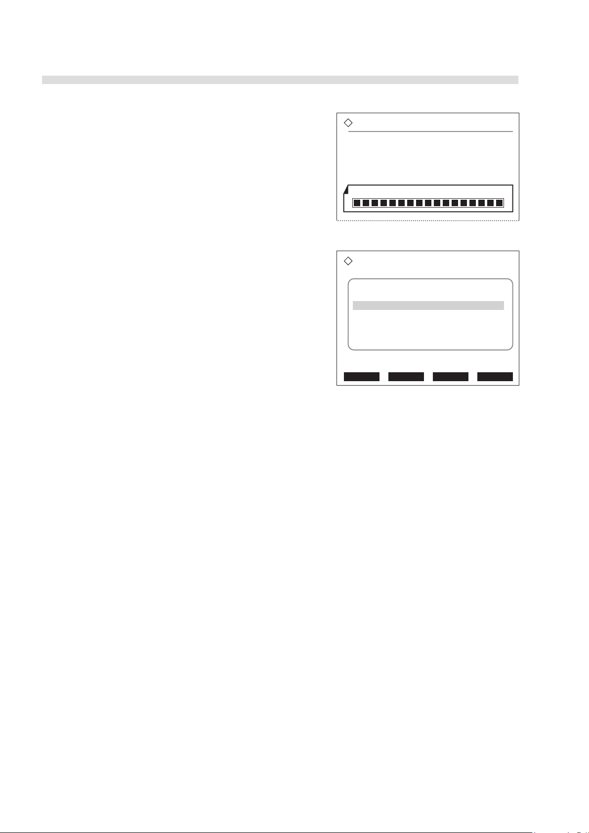
AUTION MAX AX-4030 OPERATING MANUAL
Startup
Initializing...
Please wait...
Ready for measurement
2006-01-09 10:00
Measurement start No.
0001
Test strips in feeder 1
1: 9EB
Test strips in feeder 2
2: 9EB
Menu Meas No. Strip S.G. Cal
Standby screen
• The instrument will read the parameter settings, and
then initialize the hardware.
• Warm-up will complete in 2 minutes and the
standby screen shown at right will appear. You
will see the current date and time, the factory-set
measurement start number, and test strip settings.
1-32
AX-4030
B
Page 44
AUTION MAX AX-4030 OPERATING MANUAL
System clock setup
(3100) 2006-01-09 10:00
Date
<05-12-22> (YY-MM-DD)
Time
<11:30>
1.5.2 Setting up the Printer and System Clock
Before using the instrument, load the thermal printer paper into the built-in printer and set the
system clock.
Prepare: Thermal printer paper
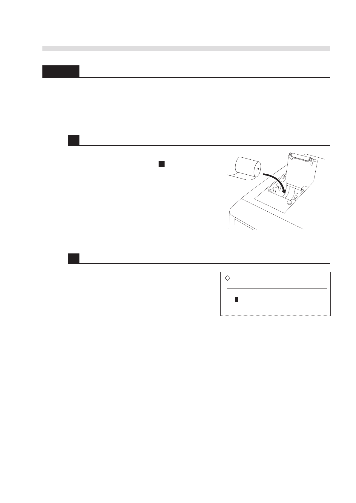
1 Load the thermal printer paper.
1 Load a roll of paper into the built-in printer.
• For more information, see steps 2 in “4.3.2
Replacing the Thermal Printer Paper” on page
4-17.
2 Set the system clock.
1 Set the clock to the current date and time.
• For detailed instructions, see “3.4.1 Setting the
System Clock” on page 3-17.
G
AX-4030
1-33
Page 45
AUTION MAX AX-4030 OPERATING MANUAL
Ready for measurement
2006-01-09 10:00
Measurement start No.
0001
Test strips in feeder 1
1: 9EB
Test strips in feeder 2
2: 9EB
Menu Meas No. Strip S.G. Cal
Standby
switch
1.5.3 Turning Off the Power
Use the following procedure to turn off the instrument.
1 Make sure the standby screen is displayed.
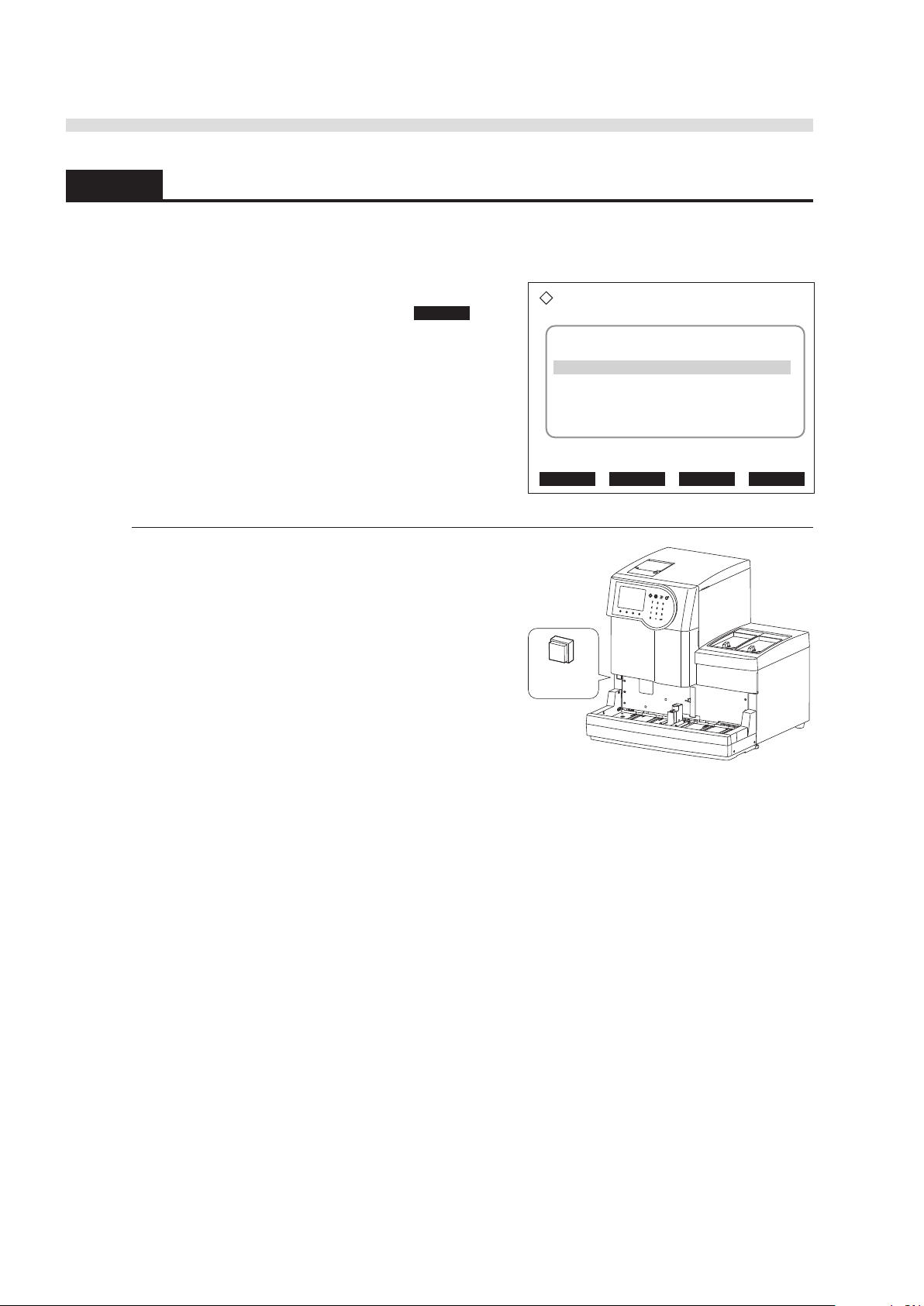
• If a different screen is displayed, press Go back to
return to the standby screen.
2 Press the standby switch.
• The light of the standby switch will turn off,
indicating the instrument has powered off.
REFERENCE: When you are to use the instrument
almost every day, keep the main power switch on
and use the standby switch to turn on or off the
instrument.
1-34
AX-4030
D
Page 46
AUTION MAX AX-4030 OPERATING MANUAL
Relocation1.6
1.6.1 Precautions in Instrument Relocation
Before relocating the instrument, read the following instructions and always take proper safety
precautions.
■ Remove the drain bottle, washing solution bottle and sampler from the
instrument.
■ Drain washing solution from the flow line. Moving the instrument with washing
solution in the flow line may damage the instrument.
■ Turn off the power by pressing the standby switch followed by the OFF side of the
main power switch. Then, disconnect the power cord.
■ Disconnect the optional hand-held barcode reader and the communication cables
for external devices, if any, from the rear panel of the instrument.
■ Make sure the front, maintenance and side covers are closed before relocating
the instrument. Moving the instrument with any of the covers open may expose
you to pathogenic microbes or damage the instrument.
■ Make sure there are no test strips left inside the instrument before relocating the
instrument. Moving the instrument with used test strips inside may expose you to
pathogenic microbes or damage the instrument.
■ For safety reasons, always move the instrument with the help of at least one other
person. Hold the bottom of the instrument with both hands and be careful not to
impact or shake the instrument. Rough handling may damage the instrument.
■ Read
the instrument.
“1.4.1 Precautions in Instrument Installation” on page 1-18 before relocating
1.6.2 Checking for Leftover Test Strips
Prepare: Protective gloves
Wear protective gloves to prevent exposure to pathogenic microbes.
AX-4030
Discard used protective gloves, test strips and liquid waste in accordance
with local regulations for biohazardous waste.
1 Check for test strips in the feeders.
1 Make sure the standby screen is displayed.
2 Open the 2 feeder covers.
1-35
Page 47
AUTION MAX AX-4030 OPERATING MANUAL
3 Return any test strips found in the feeders to the bottle.
2 Check for used test strips.
1 Pull out the waste box tray to check if there are any used test strips in the box.
• Discard the used strips, if there are any.
1.6.3 Discharging the Washing Solution
Prepare: Protective gloves and tissue paper
Wear protective gloves to prevent exposure to pathogenic microbes.
Discard used protective gloves and liquid waste in accordance with local
regulations for biohazardous waste.
1 Discharge the washing solution from the flow lines.
1 Make sure the standby screen is displayed, then press the standby switch to turn off the power.
2 Uncap the washing solution bottle.
• Place the cap on tissue paper to protect it against dust.
3 Press the standby switch to turn on the power.
• During warm-up, washing solution will be discharged from the flow lines.
1.6.4 Unplugging the Power Cord
1-36
1 Make sure the standby screen is displayed, then press the standby switch to turn off the power.
2 Press the OFF side of the main power switch on the rear panel to turn off the main power.
3 Pull out the power cord from the receptacle.
4 Disconnect the power cord from the power input terminal on the rear panel.
AX-4030
Page 48
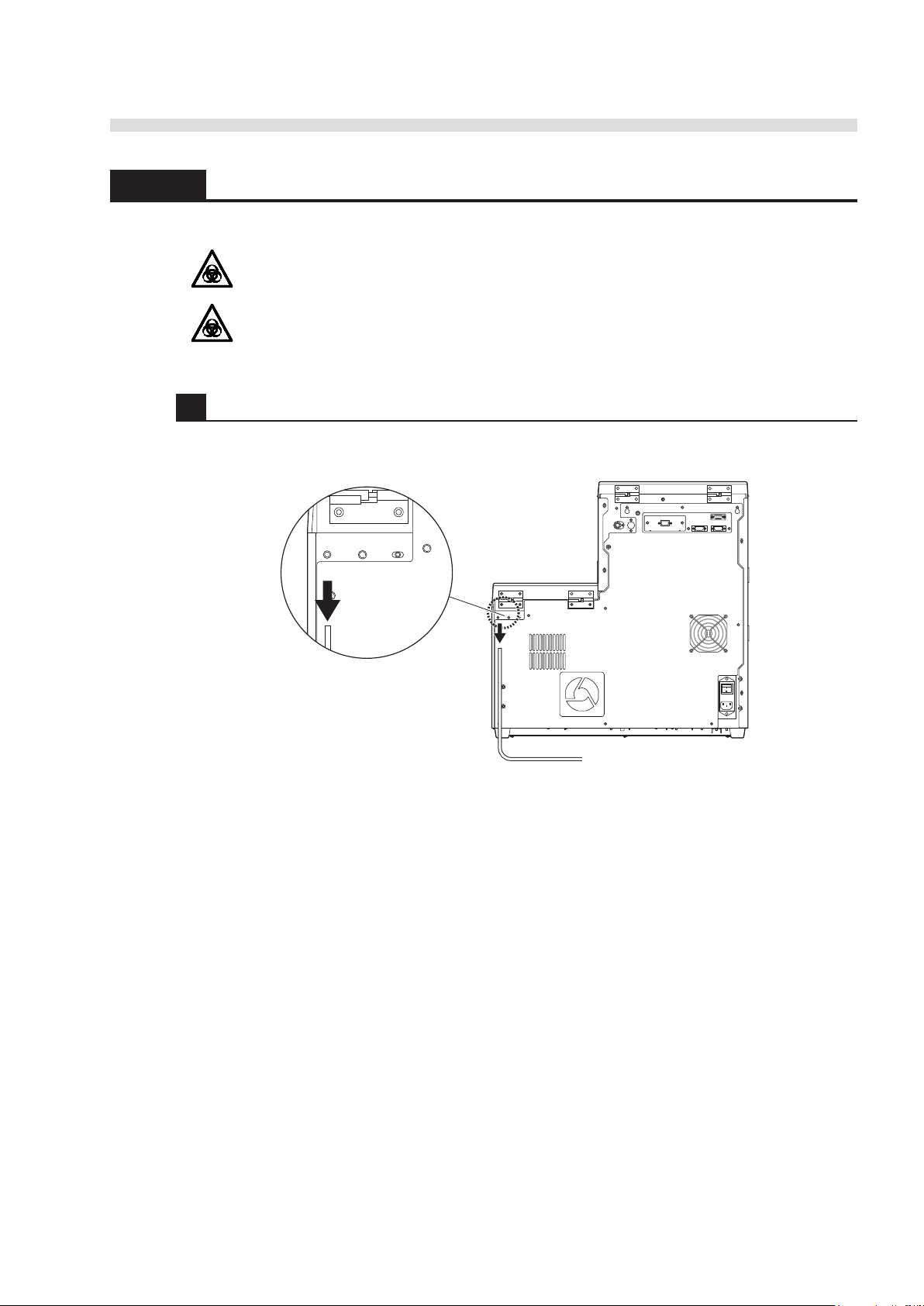
AUTION MAX AX-4030 OPERATING MANUAL
To drain bottle
WD
1.6.5 Disconnecting the Tubes, Sensor Code, and Cables
Prepare: Protective gloves
Wear protective gloves to prevent exposure to pathogenic microbes.
Discard used protective gloves and liquid waste in accordance with local
regulations for biohazardous waste.
1 Disconnect the tube of the drain bottle.
1 Disconnect the tube of the drain bottle from the drain joint “D” on the rear panel.
AX-4030
1-37
Page 49
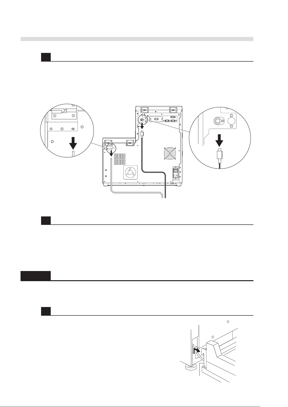
AUTION MAX AX-4030 OPERATING MANUAL
Tube
Liquid sensor cord
❷
❶
To washing solution bottle
WD
HS
Hook
2
Disconnect the liquid sensor cord and tube of the washing solution bottle.
1 Disconnect the liquid sensor cord from the washing solution sensor terminal “S” on the rear
panel.
2 Disconnect the tube of the washing bottle from the washing solution joint “W” on the rear panel.
3 Disconnect cables to the optional part and external devices.
1 If an optional hand-held barcode reader or external device is connected to the instrument,
disconnect their cables from the instrument.
1.6.6 Detaching the Sampler
Prepare: Phillips screwdriver
1 Detach the sampler.
1 Carefully lift the sampler straight upward with both
hands and pull to the front.
• This unhooks the sampler in 2 locations.
1-38
AX-4030
Page 50
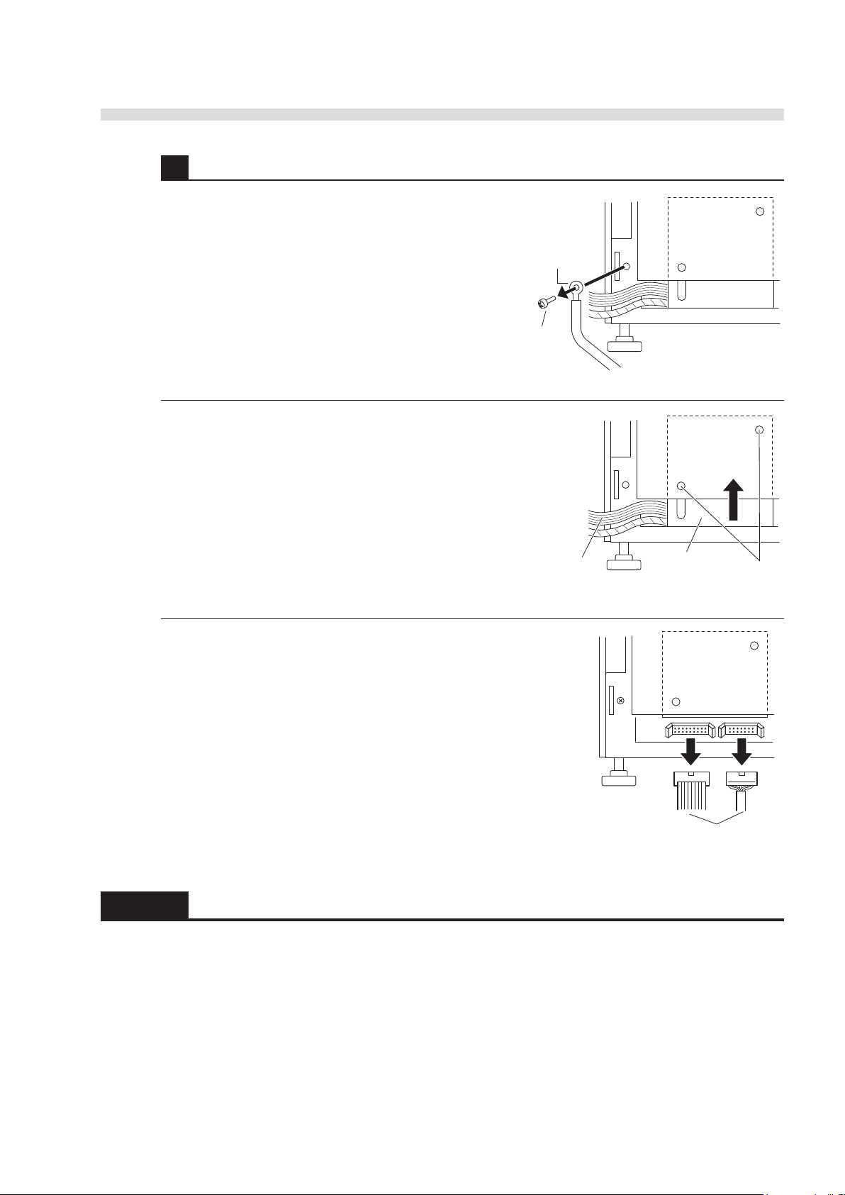
AUTION MAX AX-4030 OPERATING MANUAL
Earth line
Earth
anchoring
screw
Screw hole
Splash guard
Cable
Sampler connectors
2 Disconnect the sampler cables from the instrument.
1 Loosen the earth anchoring screw with a Phillips
screwdriver and disconnect the earth line from the
instrument.
2 Insert the tip of a Phillips screwdriver in the screw
holes on the splash guard to loosen the two screws
inside.
3 Slide the splash guard upward.
4 Temporarily tighten one of the screws using the
screwdriver to prevent the splash guard from
dropping.
5 Disconnect the two sampler cables from the
connectors on the lower part of the front panel.
• The sampler is now detached completely from the
instrument.
1.6.7 Relocating the Instrument
AX-4030
1 Move the instrument to its new location.
IMPORTANT: For safety reasons, always move the instrument with the help of at least one
other person. Hold the bottom of the instrument with both hands when carrying it.
2 See “1.4 Installation” on page 1-18 to install the instrument.
1-39
Page 51
AUTION MAX AX-4030 OPERATING MANUAL
Ready for measurement
2006-01-09 10:00
Measurement start No.
0001
Test strips in feeder 1
1: 9EB
Test strips in feeder 2
2: 9EB
Menu Meas No. Strip S.G. Cal
1 2 3 4 5
6
7
8
9
Function labels
Basic Operations1.7
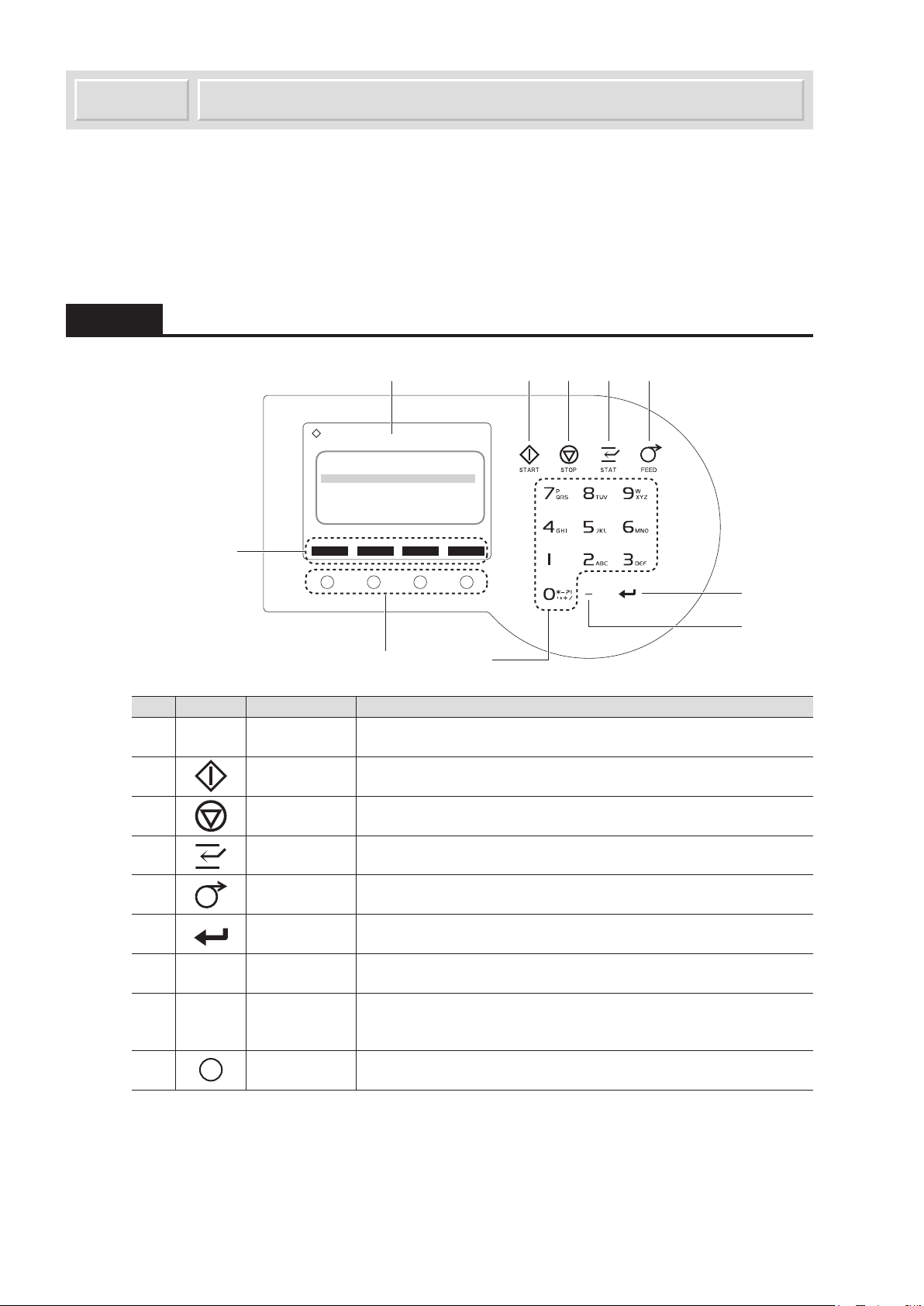
The operator panel has 16 operation keys and a 34-column by 14-line color liquid crystal display.
This section describes basic instructions you should learn in order to run urine tests and make
parameter settings.
1.7.1 Components on the Operator Panel
No. Icons Names Descriptions
1 Display Up to 4 currently available function labels appear on the lowest line of
the display.
2 Start key Press this key to start measurement.
3 Stop key Press this key to stop measurement in progress or menu operation.
4 Stat key Press this key to reserve a STAT measurement.
5 Feed key Hold down this key to advance the thermal printer paper of the built-in
printer.
6 Enter key Press this key to confirm your entry or selection or to move the cursor
down.
7 — Hyphen key Press this key to select an option for a setup item, move the cursor
between entry fields, or enter a hyphen for IDs.
8 0 to 9 Alphanumeric
keys
Use these keys to enter numeric values. On the menu screens, these
keys can work as cursor keys (see the “REFERENCE” below). For ID
entries, use these keys to enter alphabetical characters.
9 Function keys Press the function key just below the function label to activate the
REFERENCE: Using the numeric keys as cursor keys
corresponding function.
The numeric keys, 8, 2, 4, 6, double as cursor keys for selecting options on the setup screens.
The cursor key functions are disabled for alphanumeric entry fields.
8: Select the last option. 4: Select the previous option.
2: Select the first option. 6: Select the next option.
1-40
AX-4030
F
Page 52
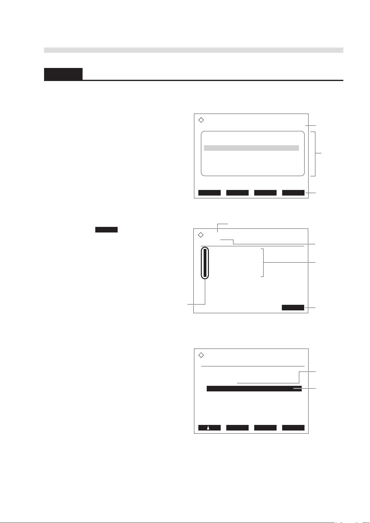
1.7.2 Screen Configuration
Ready for measurement
2006-01-09 10:00
Measurement start No.
0001
Test strips in feeder 1
1: 9EB
Test strips in feeder 2
2: 9EB
Menu Meas No. Strip S.G. Cal
Date and time
Current
settings
Function labels
View
(2300) 2006-01-09 11:07
Date
<06-01-06> - <06-01-08> (YY-MM-DD)
Measurement
[Normal & STAT measurements ]
Results
[All ]
Range of results
[Measurement No. ]
BS OK Cancel
Setup item
Selection field
or entry field
Main menu
(0000) 2006-01-09 11:00
1 Parameter settings
2 Results
3 Initial settings
4 Print
5 Maintenance
Go back
Screen number
Screen name
To select an option, press the key
of the corresponding number.
To one-level
higher screen
Options
This section describes the configuration of the screens you will see while operating the instrument.
■ Standby screen
The standby screen is initially displayed
after warm-up completes, telling you the
instrument is ready to accept instructions
from you (e.g. to measure samples or set
parameters). Always return to the standby
screen after the completion of these tasks.
AUTION MAX AX-4030 OPERATING MANUAL
■ Menu screens
Pressing Menu on the standby screen
activates the hierarchical menu system
that allows you to access various
auxiliary operation options. The
screen number can be referred to when
contacting your distributor for service.
■ Setup screens
When an option is selected on a menu
screen, the appropriate setup screen
appears. Setup screens contain one or
more setup items. Below each setup item
is a selection field for selecting an option
or an entry field for inputting numbers or
characters.
B
AX-4030
1-41
Page 53
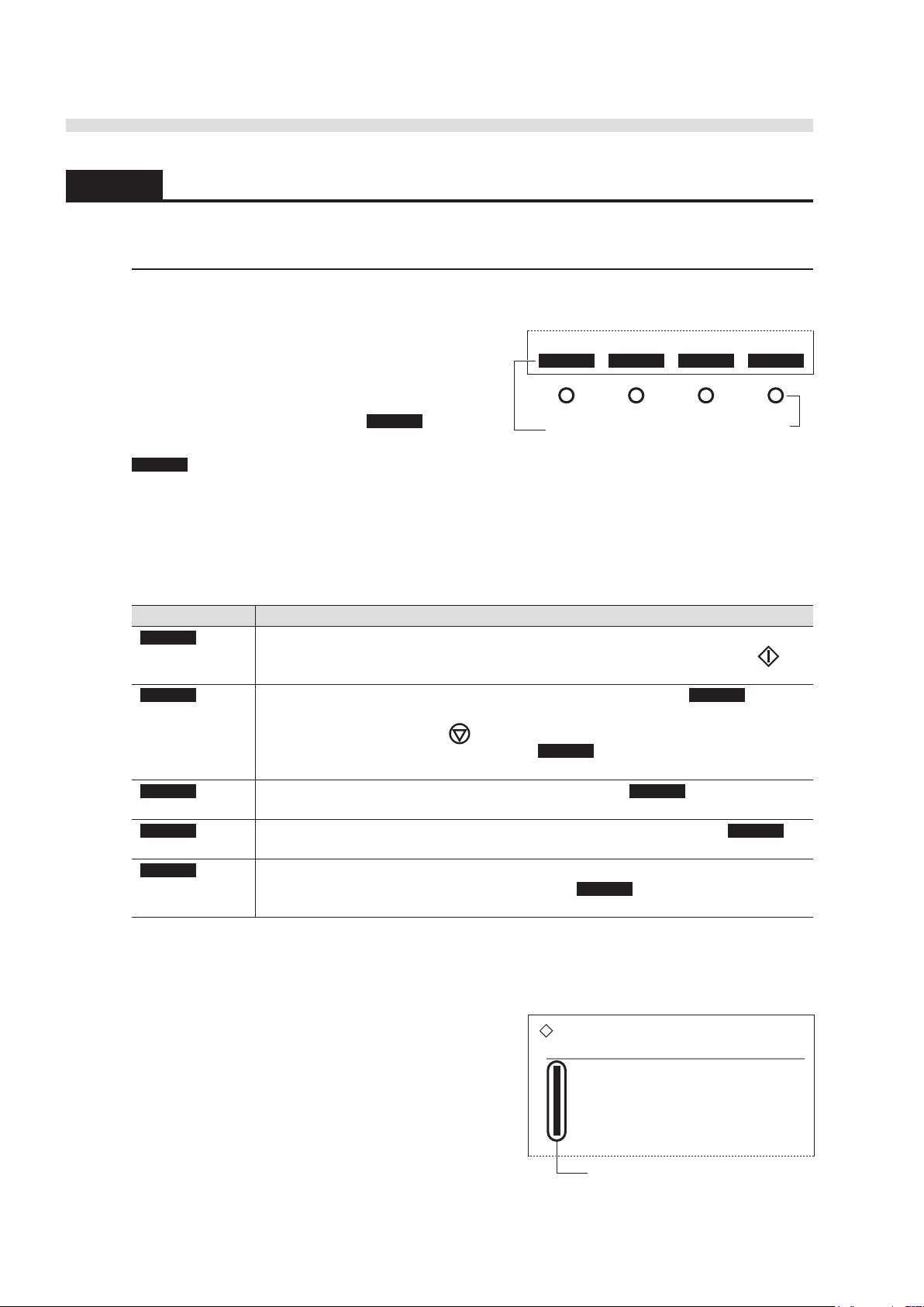
AUTION MAX AX-4030 OPERATING MANUAL
Menu Meas No. Strip S.G. Cal
Function labels
Function keys
Main menu
(0000) 2006-01-09 11:00
1 Parameter settings
2 Results
3 Initial settings
4 Print
5 Maintenance
To select an option,
press the key corresponding to this number.
1.7.3 Menu Operations and Examples
Basic Operations
■ Function labels and function keys
The lowest line of the screen contains up to four
function labels for activating different functions
depending on the status of the instrument. Each
function label corresponds to the function key (°)
just below it. For example, “Press Menu ” refers
to “press the function key below the function label
Menu ”.
Frequently used functions are also assigned to the hardware keys on the operator panel. It is
recommended to learn the functions commonly available through the measurement and setting
operations because the later chapters in this manual do not include detailed descriptions of such
functions.
Function labels Descriptions
Start
Stop This function label appears while measurement is in progress. Press Stop to
Cancel This function label appears on the setup screens. Pressing Cancel aborts all the
OK This function label appears when a warning, error, or trouble occurs. Press OK to
Go back
This function label appears when the instrument is ready for measurement. Press this
function key to start measurement, or restart the suspended measurement. The
key on the operator panel also works in the same way.
suspend the measurement process. The instrument then shifts to the end process
before going on standby. The
Until the end process begins, you can press
measurement.
settings you made and brings you back to the previous screen.
clear the problem.
This function label appears on the menu screens or after the completion of a task. The
instrument displays the previous screen each time
reaching the standby screen.
key on the operator panel works in the same way.
Start to resume the suspended
Go back is pressed until finally
■ Menu screen operations
To select an option from a menu screen, press the
numeric key corresponding to the number of that
option.
1-42
AX-4030
Page 54
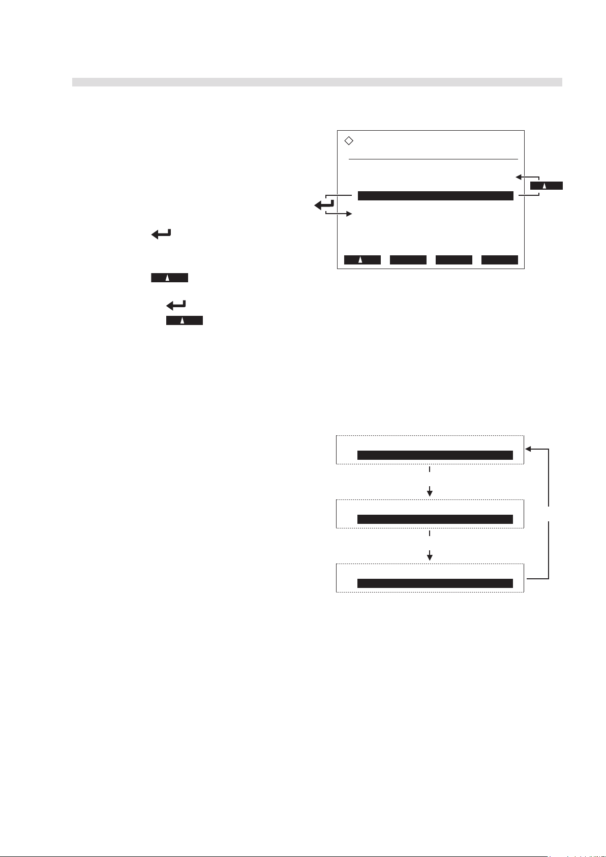
AUTION MAX AX-4030 OPERATING MANUAL
View
(2300) 2006-01-09 11:07
Date
<06-01-06> - <06-01-08> (YY-MM-DD)
Measurement
[Normal & STAT measurements ]
Results
[All ]
Range of results
[Measurement No. ]
BS OK Cancel
Measurement
[Normal & STAT measurements ]
Measurement
[Normal measurement ]
Measurement
[Check measurement ]
hyphen
hyphen
hyphen
Example: To select an option for [Measurement]
■ Moving between setup items
The setup screen may contain two or
more setup items. For example, the
[View] screen shown at right has four
setup items, [Date], [Measurement],
[Results], and [Range of results].
• To go down to the next setup item,
press on the operator panel.
• To go up to the previous item,
press .
• Pressing with the cursor at the lowest setup item brings the cursor to the top.
Pressing with the cursor at the top item moves the cursor to the bottom.
REFERENCE: About the cursor
The cursor for this instrument refers to the highlighted portion on the display and prompts you
to change options or to type in numeric values or text.
■ Selecting an option
Below the setup item (e.g. [Measurement]
in the right figure), the currently selected
option is displayed at first. The setting
changes each time you press the hyphen
key. For example, if the setup item has 4
selectable options, pressing the hyphen key
four times allows the first option to appear
again.
REFERENCE: The numeric keys double
as cursor keys.
8: Select the last option.
2: Select the first option.
4: Select the previous option.
6: Select the next option.
AX-4030
1-43
Page 55
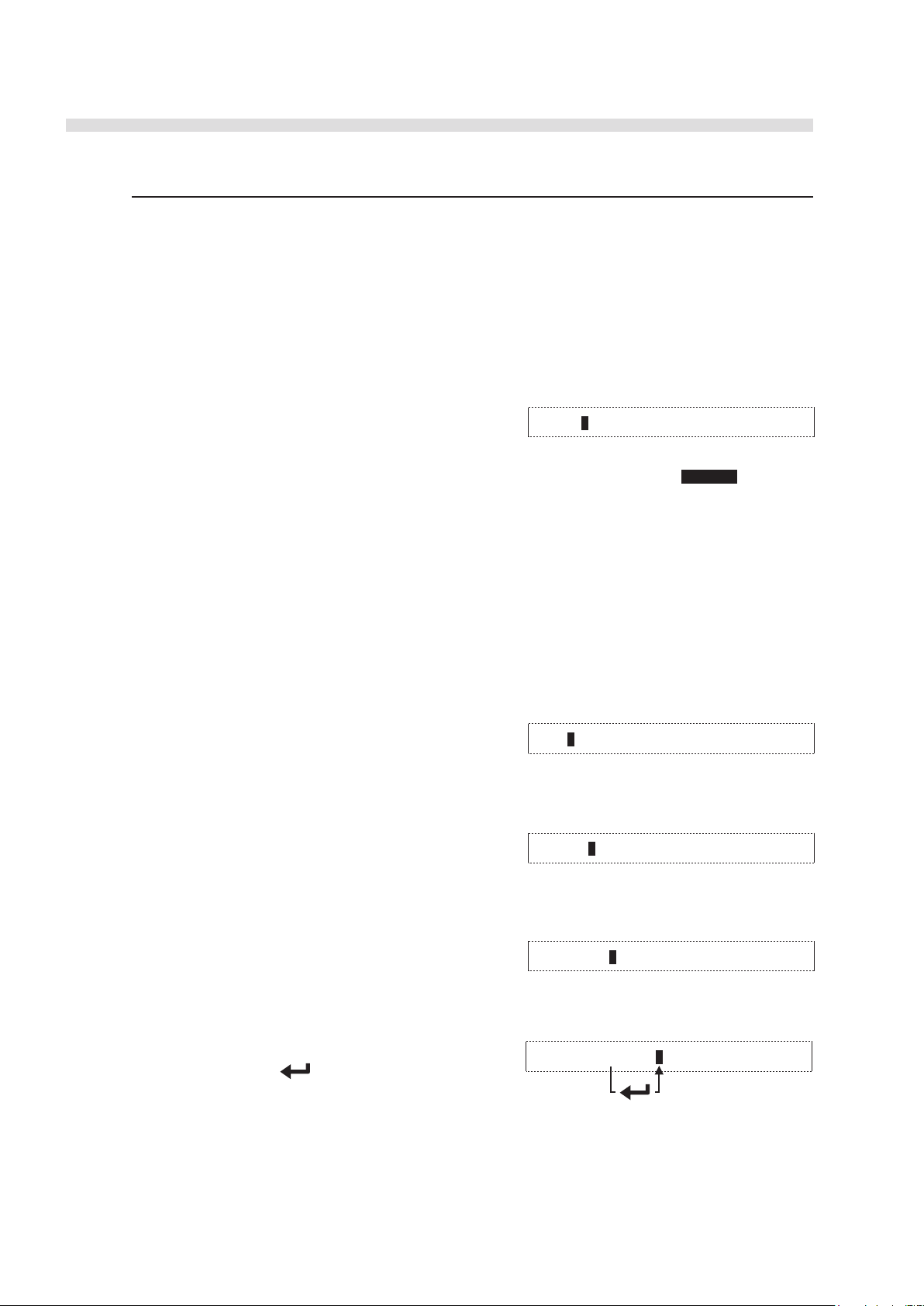
AUTION MAX AX-4030 OPERATING MANUAL
<1302>
<06-11-07>
<06-04-07>
<06-04-15>
<06-04-15> - <05-11-07>
Example: To specify a range of days
Entering Alphanumerics
Use the keys on the operator panel to enter numeric values and alphabetic characters in the entry
fields.
■ Numeric values
Entry fields that accept numeric values (e.g. a measurement number) have the cursor at the rightmost digit.
For example to enter “1302”:
1 Press the numeric keys in the following order, 1, 3,
0, and 2.
REFERENCE: To correct the entry, for example, from “1302” to “1402,” press BS three
times to make it “0001”, then type in “4”, “0”, and “2”. The cursor cannot move through digits.
■ Date
Entry fields that accept date information have the cursor at the “year” entry position at first.
REFERENCE: The default date display format is “YY-MM-DD (year-month-day)”. If you are using
a different format, “month-date-year” or “date-month-year”, set the date accordingly.
For example, to enter April 15th, 2006:
1 To enter the year “06”,
press 0 and 6 in that order, and
press the hyphen key to move to the month entry
position.
2 To enter the month “04 (April)”,
press 0 and 4 in that order, and
press the hyphen key to move to the day entry
position.
3 To enter the day “15”,
press 1 and 5 in that order.
REFERENCE: When specifying a period of days...
To move the cursor from the “start” field to the
“end” field, press .
REFERENCE: To modify the entry, just enter a new value. For example, to change “04” to “06”,
place the cursor at “04” and press 0 and 6 in that order. The cursor cannot move between the
first and second digits (e.g. between “0” and “4”).
1-44
AX-4030
Page 56
AUTION MAX AX-4030 OPERATING MANUAL
<-----------------I>
<IM-060109-00134>
■ ID
This instrument can assign an ID to each sample or control. An ID can contain up to 18 digits, and
include numbers, alphabetic characters (case sensitive), and hyphens (-).
For example, to enter “IM-060109-134”:
1 Press 4 four times to enter “I”.
Each time 4 is pressed, the digit at the cursor will
rotate in the order of “4”, “G”, “H”, “I”, “g”, “h”,
“i” and back to “4” again.
2 Enter all numbers and characters you want in the
same way.
REFERENCE: To enter the same number or character consecutively
Press the hyphen key. For example, to enter “AA”, enter “A”, press the hyphen key, and
enter “A”. Use the same method to enter different characters assigned to the same keys. For
example, to enter “NO”, enter “N”, press the hyphen key, and enter “O”.
REFERENCE: To enter a special character
Use the 0 key. Number “0” and special characters rotate in the following order each time 0 is
pressed:
0 (zero) → * (asterisk) → - (hyphen) → ? (question mark) →
! (exclamation mark) → . (period) → , (comma) → + (plus) → / (slash) → 0
■ To correct an entry
To correct an entry, press BS . The right-most digit is deleted each time BS is pressed.
You cannot jump to the second or later digits to delete it. For example, to change “1302” to “1402”,
press BS three times to delete “302”. With the field containing “0001”, enter “4”, “0”, and “2”
in that order.
AX-4030
1-45
Page 57

AUTION MAX AX-4030 OPERATING MANUAL
1-46
AX-4030
Page 58

Chapter
AUTION MAX AX-4030 OPERATING MANUAL
2
Measurement
2.1 Before Making Measurements.................................2-2
2.1.1 Flowchart of Operational Procedure ...........
2.1.2 Measurement and Calibration .....................
2.1.3 Measurement Terminology .........................
2.1.4 Sample Containers and Sample Racks ......
2.2 Measurement Precautions .......................................2-9
2.2.1 Handling the Instrument ..............................
2.2.2 Handling Samples .....................................2-10
2.2.3 Handling Test Strips .................................2-11
2.3 Preparation for Measurement................................2-12
2.3.1 Checking Wastes and Consumables ........2-12
2.3.2 Turning on the Power ...............................2-14
2.3.3 Loading Test Strips into the Feeders ........2-16
2.3.4 Assigning the Type of
Test Strips to the Item Racks ........2-19
2.3.5 Preparing Samples ...................................2-21
2.4 Measurement Operations ......................................2-23
2.4.1 Normal Measurement: Measuring
Samples Continuously ...................
2.4.2 Port STAT Measurement: Measuring
a Higher Priority Sample
2.4.3 Rack STAT Measurement: Measuring
Higher Priority Samples .................2-31
................2-27
2-2
2-3
2-4
2-7
2-9
2-23
AX-4030
2.5 S.G. Calibration.......................................................2-34
2.5.1 Preparing S.G. Standard Solutions ...........
2.5.2 Starting S.G. Calibration ...........................
2.6 Control Measurement.............................................2-38
2.7 Check Measurement...............................................2-43
2.8 Displayed and Printed Reports .............................2-49
2.8.1 Displayed Results Report .........................
2.8.2 Printed Results Report ..............................
2.8.3 Abnormal Results List ...............................
2.8.4 Error and Trouble List
(Automatic Report) .......................
2.8.5 Trouble List (Manual Report) ...................
2.8.6 Check Measurement Result Report ..........
2.8.7 List of Current Parameter Settings ...........
2-34
2-36
2-49
2-50
2-54
2-54
2-55
2-56
2-57
2-1
Page 59
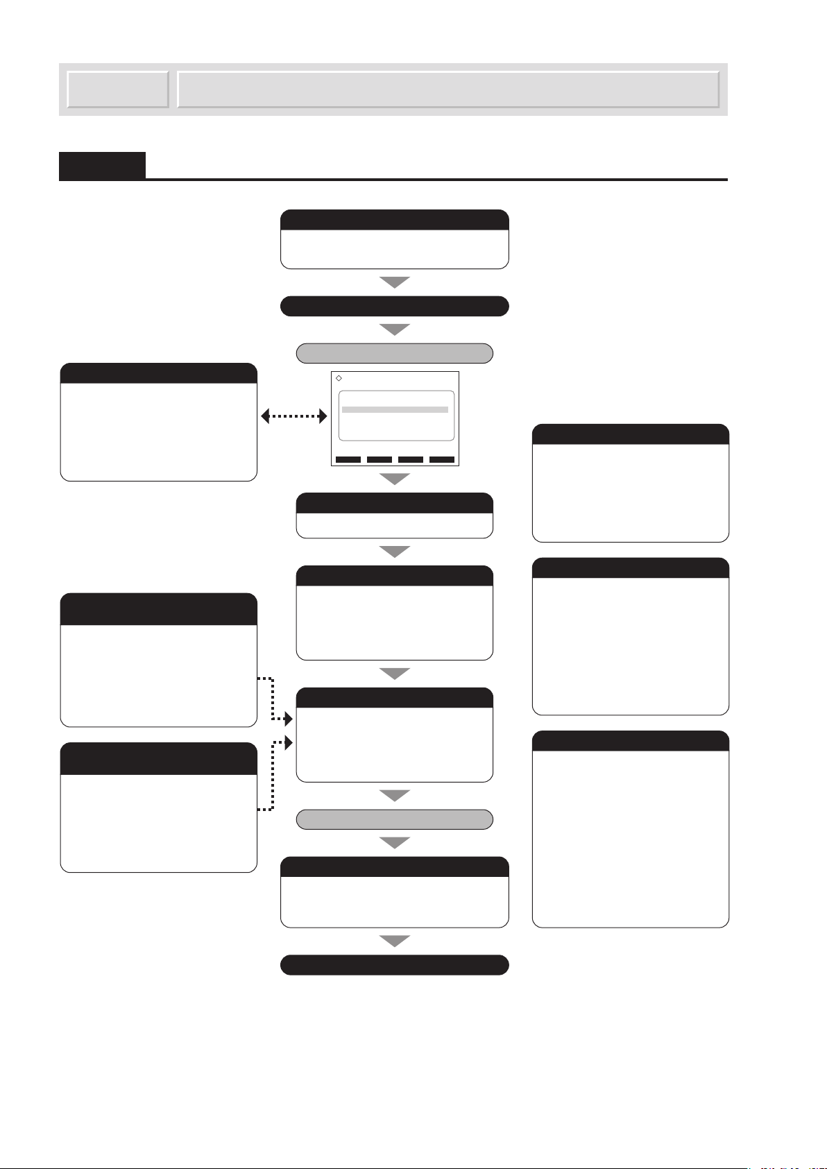
2-2
AX-4030
AUTION MAX AX-4030 OPERATING MANUAL
F
Check the instrument
Press standby switch to power on.
Press standby switch to power off.
Standby screen
Standby screen again
1. Check for used test strips and liquid waste.
2. Check the washing solution and printer paper.
Load test strips
1. Load test strips into the feeders.
Make S.G. calibration
1. Prepare S.G. standard solutions and
measure S.G. standard values.
2. Load standard solutions.
3. Input standard solution values.
4. Start S.G. calibration.
* It is recommended to perform S.G. calibration
once a month.
Control measurement
1. Prepare test strips and check the main
feeder.
2. Prepare controls.
3. Load controls into STAT and control
rack.
4. Load rack into sampler.
5. Set start measurement No.
6. Press START.
7. When completed, take out sample
racks.
Check measurement
1. Clean strip transportation path inside
instrument.
2. Choose Check measurement from
menu.
3. Select feeder number for first check
strip.
4. Load check strip into feeder.
5. Press START to measure strip.
6. Print the first result.
7. Measure second test strip in the same
way.
8. Print the second result.
9. Interpret the results.
Prepare samples
1. Label sample tubes with barcodes,
if needed.
2. Pour samples into tubes.
3. Load samples into sample racks.
4. Load sample racks into sampler.
Normal measurement
1. Check the type of test strips and main
feeder.
2. Set the measurement start No.
3. Press START.
4. After completion, take out samples.
Daily maintenance
1. Return test strips in the feeders to the bottle.
2. Discard used test strips and clean waste box.
3. Discard liquid waste.
Set parameters
• Set the type of test strips for each feeder.
• Select the main feeder.
• Assign the type of test strips to the item
racks.
• Set the measurement start No.
*Change the measurement No. assignment and
result format as needed.
Port STAT measurement
For single sample
1. Prepare a STAT sample.
2. Place the sample in the STAT port.
3. Press STAT.
4. Set the type of test strips, measurement
No., and ID.
5. Press START.
6. When completed, take out the sample.
Rack STAT measurement
Max. 7 samples
1. Prepare STAT samples.
2. Load the samples into the STAT and
control rack.
• Press STAT to set the type of test strips
and measurement start No.
3. Load the STAT and control rack into the
sampler.
Ready for measurement
2006-01-09 10:00
Measurement start No.
0001
Test strips in feeder 1
1: 9EB
Test strips in feeder 2
2: 9EB
Menu Meas No. Strip S.G. Cal
Before Making Measurements2.1
2.1.1 Flowchart of Operational Procedure
Page 60

2.1.2 Measurement and Calibration
This instrument is capable of 4 types of measurements: normal measurement and STAT
measurement for measuring patient samples, control measurement made to maintain measurement
precision, and check measurement for checking to see that the instrument is working correctly.
■ Normal measurement
Normal measurement continuously measures a number of samples loaded in the sample racks.
A sample rack can contain up to 10 samples. Place the sample racks with samples in the sampler
and press the start key. The instrument then automatically transports the sample racks, aspirates
the samples in order, and obtains the results. Up to 5 sample racks (50 samples) can be loaded
into the sampler for one-way transportation, and up to 10 sample racks (100 samples) for loop
transportation. For identification purposes, the results are given under serial measurement numbers,
port numbers, and ID numbers from barcodes.
* The instrument is factory-set to the one-way transportation mode. If you prefer loop transportation to measure more
samples at a time, contact your distributor.
* For more information about measurement numbers and rack-port numbers, see the next page.
AUTION MAX AX-4030 OPERATING MANUAL
■ STAT measurement
STAT measurement is used to interrupt ongoing normal measurements and measure one or more
urgent samples. There are two types of STAT measurements:
Port STAT measurement: Measures a single sample loaded into the STAT port. If you have
a sample to test urgently, you can load the sample into the STAT
port to interrupt normal measurements in progress.
Rack STAT measurement: Interrupts normal measurements in progress to measure up to 7
samples loaded into the STAT and control rack.
■ Control measurement
The specified controls should be measured at regular intervals to maintain the precision of the
instrument. Use the STAT and control rack to load the controls. Up to 3 types (or 3 concentrations)
of controls can be used at a time.
■ S.G. calibration
S.G. calibration is for calibrating the instrument using two types of S.G. standard solutions (low
and high solutions) that the operator prepares. It is recommended to perform S.G. calibration once a
month.
■ Check measurement
If you suspect there is something wrong with obtained results, use the supplied check strips to
check if the instrument is working correctly.
F
AX-4030
2-3
Page 61
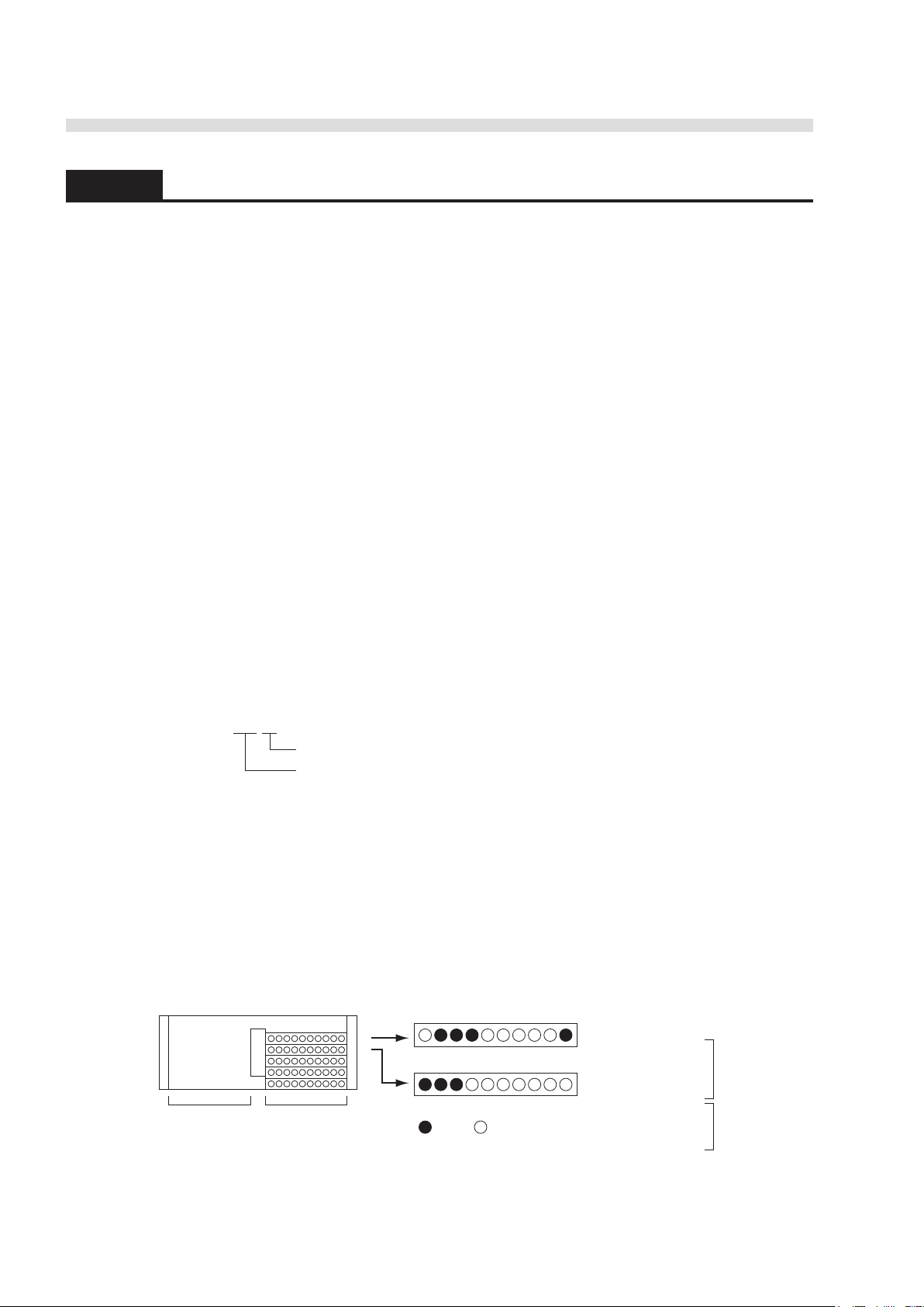
2-4
AX-4030
AUTION MAX AX-4030 OPERATING MANUAL
Port number
Rack number
Po. 001-01
1
Unloading side
2
3
4
5
Loading side
1 2 3 4 5 6 7 8 9 Port numbers
Sample rack 1
Sample racks Printed results report
Port No.
0002
0003
0004
0010
0011
0012
0013
1
10
1 2 3 4 5 6 7 8 9 Port numbers
2
Sample Empty
10
Sample rack 2
2.1.3 Measurement Terminology
■ Batch
A batch is a group of samples that the instrument measures successively. For practicality’s sake, a
batch includes any number of samples measured after the start key has been pressed and until the
instrument puts itself on standby again.
■ Measurement number
A measurement number is a 4-digit number given to each sample (or a port of the sample rack),
and appears like “No. 0001” on displayed and printed results reports. Once you have set the
measurement number for the first sample, the instrument automatically assigns consecutive
numbers to the following samples. You have two alternative options for measurement numbering.
One is to assign sequential numbers through batches, and the other is to reset the number at the
beginning of each batch. Furthermore, you can assign the numbers either to samples or sample
rack ports regardless of whether the ports have samples or not (see “3.2.3. Configuring the
Measurement Numbering Method” on page 3-6). The measurement number is reset to “0001” at
power-on.
■ Rack-port number
A rack-port number identifies the location of a sample by the sample rack port where the sample
has been loaded, and consists of a 3-digit rack number and a 2-digit port number. Rack numbers
are assigned to sample racks in the order in which they are loaded into the sampler and start with
“001”. Port numbers are assigned to the ports of the sample rack and start with “01” for port 1. The
rack-port number appears like “Po. 001-01” on the displayed and printed results reports.
Example: First sample rack 001-01 001-02 001-03 001-04 .........
Second sample rack 002-01 002-02 002-03 002-04 .........
REFERENCE: Four-digit port numbers for result printing, transmitting, and viewing operations
Port numbers in a different format are used to specify a range of results you want to print,
transmit, or review on the screen (see page 3-8). They are 4-digit numbers from 0000 to 9999,
which identify the order of the sample racks in the sampler and the position of the ports where
samples are present.
001-10
002-10
Page 62
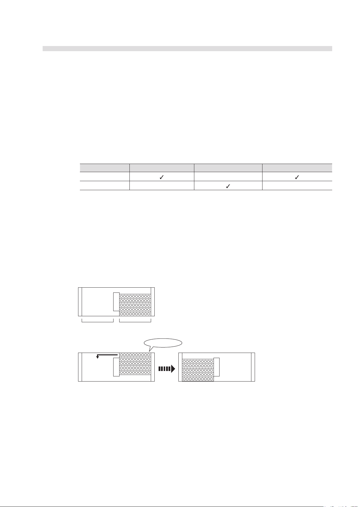
AUTION MAX AX-4030 OPERATING MANUAL
Start measurement
1
Unloading side
How to load sample racks
Transport direction
2
3
4
5
Measuring
Loading side
Sample racks are transported to the
unloading side after aspiration.
Completed
■ ID
With the barcode reader, the instrument can manage individual samples by IDs read from barcoded
sample tubes. An ID can contain up to 18 digits and can include numbers, alphabet and special
characters (see page 1-45). For port STAT measurement, you can manually input IDs by key
operation. The ID edit feature is helpful to manually modify IDs that are misread by the barcode
reader during measurement.
REFERENCE: Use of the barcode reader
A barcode reader is built into the instrument as a standard feature, and a hand-held barcode
reader is optionally available. The following table lists the ID-managed measurement tasks
supported by each barcode reader.
Barcode readers Normal measurement Port STAT measurement Rack STAT measurement
Built-in type
Hand-held type N/A N/A
N/A
■ Sample rack transportation
The instrument supports two methods for transporting sample racks in the sampler: one way and
loop. The instrument is configured for one-way transportation when shipped from the factory, and
can be changed to loop transportation as needed. For more information, contact your distributor.
One-way transportation (standard)
Up to 5 sample racks (50 samples) can be loaded on the loading side (right side) of the sampler.
The racks are discharged to the unloading side (left side) in turn as sample aspiration finishes.
AX-4030
2-5
Page 63
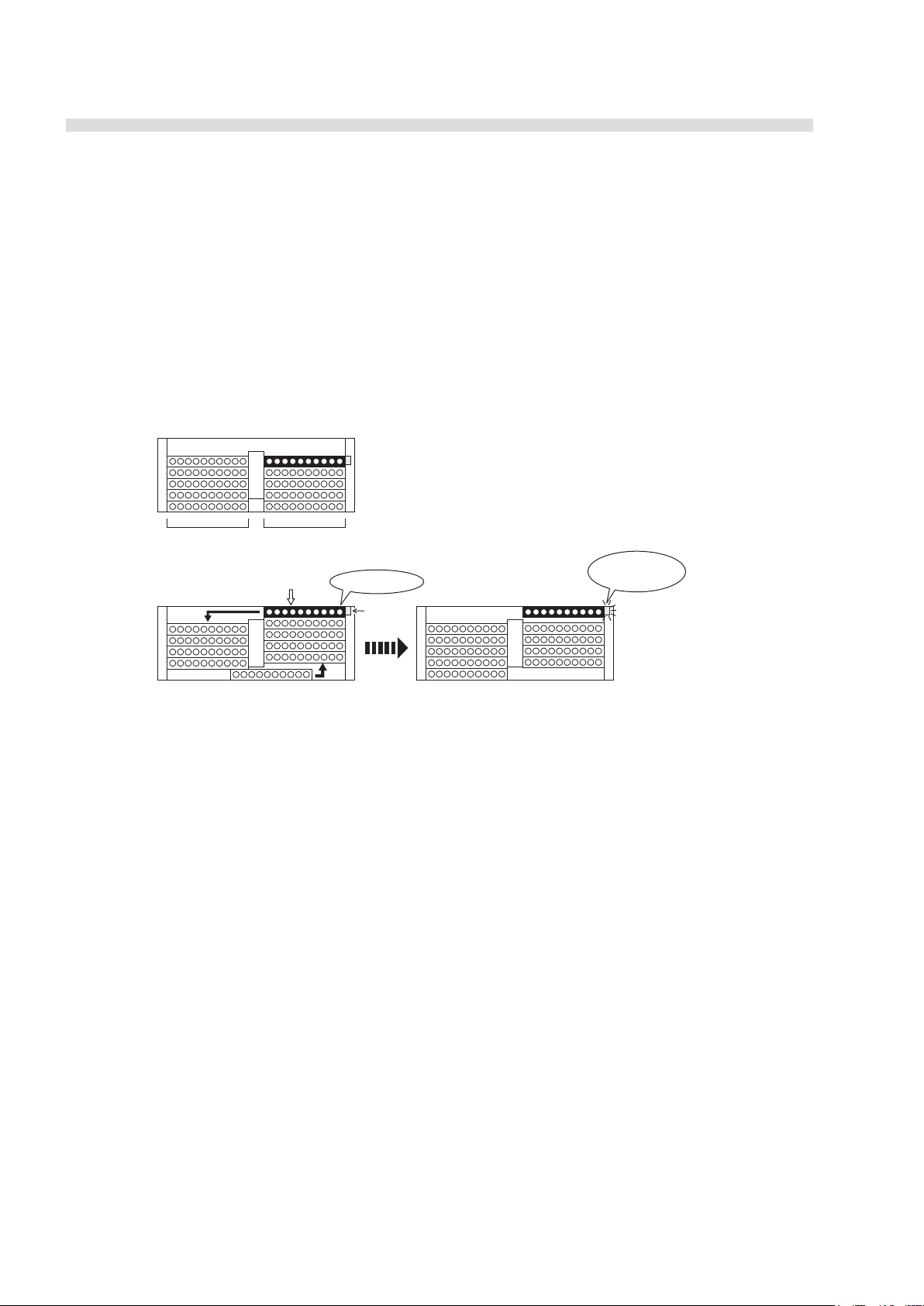
AUTION MAX AX-4030 OPERATING MANUAL
Start measurement
Start rack
10
9
8
7
6
Start rack
Unloading side
How to load sample racks
Transport direction
2
3
4
5
Stop when start
rack is detected.
Measuring
Rack
detector
Loading side
Loop transportation
A total of 10 sample racks can be loaded in the sampler at a time: 5 racks on the loading side and
another 5 racks on the unloading side. This means a maximum of 100 samples can be measured
continuously.
The start rack must be placed at the beginning of a batch, and item racks or normal racks, in
remaining locations (numbered 2 to 10 in the figure below). These racks are circulated in the
sampler as the samples are aspirated, and the instrument automatically stops aspiration the next
time it detects the start rack. To employ loop transportation, contact your distributor and ask to
have parameter settings changed.
2-6
AX-4030
Page 64
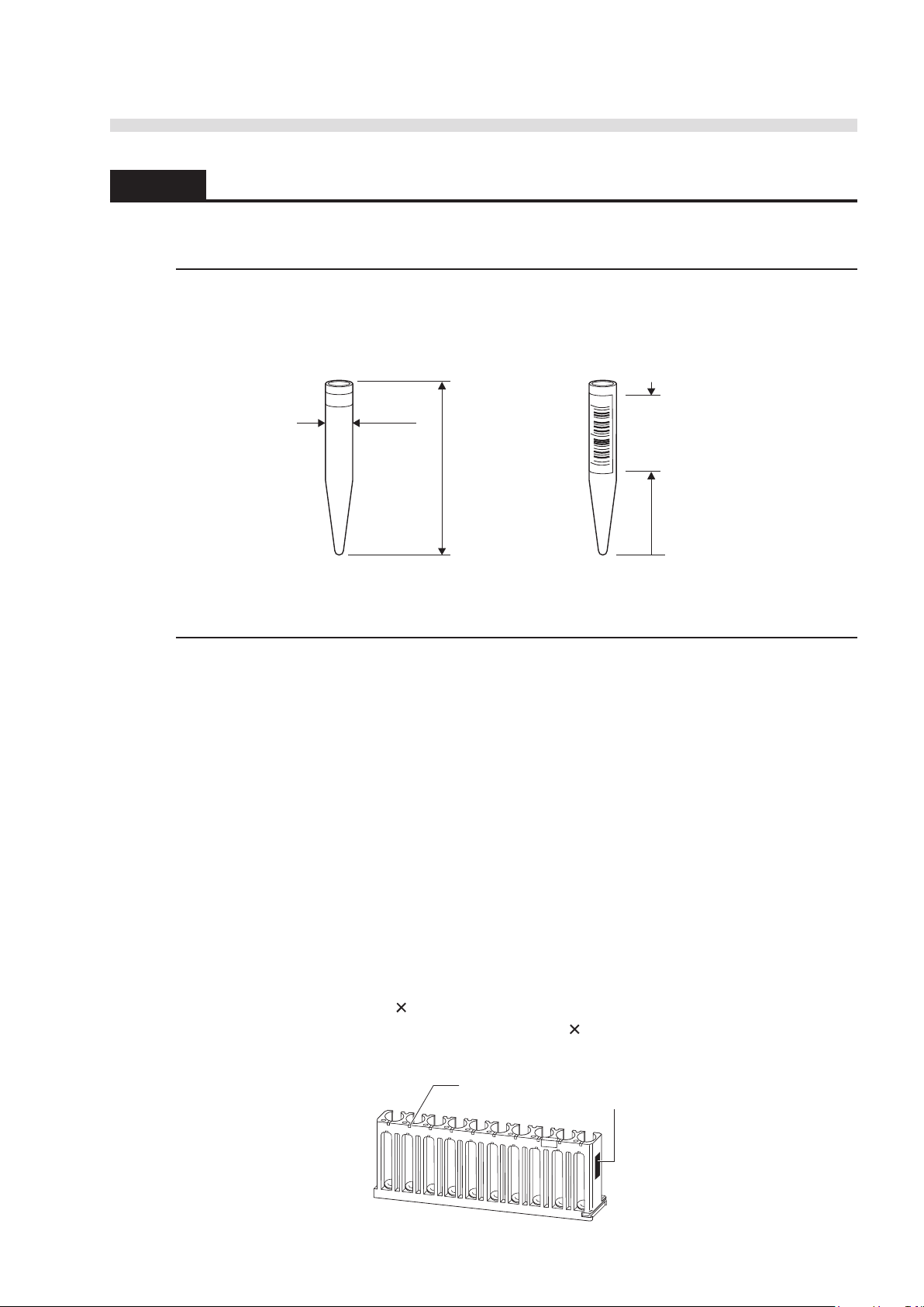
AUTION MAX AX-4030 OPERATING MANUAL
Min. 30 mm
Min. 5 mm
105 mm
15.8 mm
Sample tube Barcode labeling
Gray adapters
Black label
2.1.4 Sample Containers and Sample Racks
Sample Containers
Use the sample tubes that comply with the standards shown below. To have the built-in barcode
reader read barcodes, place the labels in the correct position on the tubes.
Sample Racks
Four types of sample racks are available for use with the instrument. These racks can be identified
by the markers on the front.
■ Item racks
The item racks are mainly used for normal measurement, and allow the instrument to automatically
pick up the appropriate type of test strips for these racks from one of the two feeders.
Each item rack supplied with the instrument has a different rack ID (#01 to #10). For successful
use of the item racks, assign one of the two feeders to each rack ID before testing samples. For
example, you may assign feeder 1 to item racks #01 to #05, and feeder 2 to #06 to #10. For detailed
instructions, see “2.3.4 Assigning the Type of Test Strips to the Item Racks” on page 2-19.
For sample preparation, load samples into the item rack assigned to the feeder that contains the test
strips to apply. When detecting the item rack, the instrument automatically ejects the correct test
strips from the feeder. This saves you the trouble of manually exchanging test strips.
The rack IDs are factory-set to “ ” on the [Rack assignment for test strip] screen which means that
the test strips in the main feeder are used. Always select “ ” in a two-way communication system
where the type of test strips is specified by the host.
D
AX-4030
2-7
Page 65
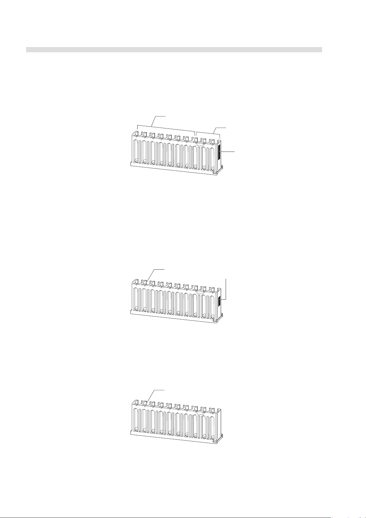
AUTION MAX AX-4030 OPERATING MANUAL
Orange adapters (ports 1 - 7)
Blue adapters (ports 8 - 10)
Black label
Light blue adapters
Black label
Gray adapters
■ STAT and control rack
The STAT and control rack is dedicated to STAT measurement and control measurement.
STAT measurement requires samples to be loaded into ports 1 to 7, and control measurement
requires controls to be loaded into ports 8 to 10.
■ Start rack
When the rack transportation method is set to “loop”, place the start rack at the beginning of a
batch, and items racks (or normal racks) in the 2nd to 10th positions. The start rack has a black label
that informs the instrument of the beginning and end of the batch to avoid measuring the same
sample twice. In other words, when the racks are completely circulated in the sampler and the start
rack returns to the initial position, the instrument detects the black label and automatically stops
measurement.
■ Normal rack
The separately sold normal racks can also be used for normal measurement. These racks do not
have rack IDs. So, samples in the normal racks are always measured with the test strips from the
main feeder.
2-8
AX-4030
D
Page 66
Measurement Precautions2.2
The following sections describe precautions you should take when
handing instrument, samples, and test strips. When you use the
instrument for the first time, read through these sections before start
measurement.
2.2.1 Handling the Instrument
This instrument is to be operated by qualified persons only. A qualified
person is one having adequate knowledge of clinical testing and the
disposal of infectious waste. Thoroughly read this operating manual
before use. Anyone who operates the instrument for the first time must be
assisted by a trained person.
AUTION MAX AX-4030 OPERATING MANUAL
Never touch the nozzle, tubing, or other parts where sample may adhere
with unprotected hands. During cleaning or maintenance of these parts,
wear protective gloves to prevent exposure to pathogenic microbes.
Discard used samples, liquid waste, parts, and instrument in accordance
with local regulations for biohazardous waste.
Read “1.4.1 Precautions in Instrument Installation” on page 1-18, and
ensure the instrument is installed in a proper environment before turning
on the power.
Do not place containers or bottles that contain liquid on the instrument.
Spilling inside the instrument may cause damage to the components.
Never fail to clean or wash the specified components of the instrument
to maintain measurement quality. For more information, see chapter 4
“Maintenance”.
If you detect abnormal odors or noise, immediately turn off the standby
switch and then main power switch, and unplug the power cord.
Continuous operation in such condition may result in fire or damage to the
instrument and consequently lead to personal injury.
AX-4030
In case of instrument trouble, contact your local distributor for repair.
Unauthorized servicing or remodeling can damage the instrument and
consequently lead to personal injury.
Alcohol is sometimes needed to prepare measurements. Alcohol is readily
combustible, therefore handle it carefully and keep away from flames,
electrical sparks and sources of heat. Also, ventilate the room sufficiently
during use.
2-9
Page 67
AUTION MAX AX-4030 OPERATING MANUAL
2.2.2 Handling Samples
TAKE THE UTMOST CARE WHEN HANDLING URINE. This instrument uses
urine as sample and as an ingredient of control solution. Urine may be
contaminated by pathogenic microbes that can cause infectious diseases.
Improper handling of urine may cause infection to the user or other
individuals by pathogenic microbes.
Discard used samples, parts and liquid waste in accordance with local
regulations for biohazardous waste.
■ Samples must be fresh urine collected within an hour.
If samples cannot be measured within an hour, seal and keep them refrigerated. Leaving samples at
room temperature for 2 hours or more may alter chemical composition of the samples. Refrigerated
samples must be brought to the measurement environment temperature before testing.
■ Mix each sample well before measurement. Do not centrifuge samples.
Centrifuging may cause blood cells to precipitate, whereby producing incorrect results for some
measurement items.
■ Remove bubbles and a film from the surface of the sample with tissue paper, etc.
The liquid level of the sample cannot be correctly detected if covered in bubbles and a film. If it
is, the instrument cannot aspirate the volume of sample required for measurement, thus producing
incorrect results.
■ Use samples as collected.
Do not add disinfectant or detergent. Preservatives may affect results and should be evaluated
before use.
■ Do not place samples where exposed to direct sunlight.
Direct sunlight can alter the quality of samples, whereby producing incorrect results.
■ Hematuria and dense turbid urine may affect S.G. and color-tone measurements.
Measuring hematuria contaminates the S.G. cell, consequently producing incorrect results. The
actual color of the macroscopic hematuria (about 10,000 red blood cells/μL) may not correspond
with the result determined by the instrument. Measurement of dense turbid urine may produce
incorrect S.G. results.
2-10
■ Samples containing ascorbic acid can affect measurement results.
Measuring samples with ascorbic acid can produce lower glucose and occult blood values than
actual levels.
■ Drug-administered urine and visual hematuria can affect measurement results.
Measurements of drug-administered urine and visual hematuria can produce incorrect results. The
instrument alerts you to the error by adding a “!” sign on the displayed and printed reports.
AX-4030
K
Page 68

2.2.3 Handling Test Strips
REFERENCE: Purchase the test strips specified for the instrument because the strips are not
supplied with the instrument.
■ Use only test strips specified for the instrument.
“AUTION Sticks 9EB” are available for use with the instrument. Carefully read the package insert
and observe the expiration date.
■ Check the test strips before use.
Do not use the test strips beyond the expiration date or test strips having discolored pad area even if
they are within the expiration date.
■ Prepare the test strips just before testing.
Take as many test strips as you need out of the bottles and load them into the feeders just before
testing. Each feeder can contain up to 200 test strips (equivalent to 2 bottles), but the quality of the
strips is assured only for 3 days. Test strips absorb moisture in the air, which may alter their quality
and produce incorrect results. The test strip bottles should be securely capped immediately after
taking out the strips.
AUTION MAX AX-4030 OPERATING MANUAL
■ Do not touch the pad area on the test strips.
Touching the test strips can cause sebum to adhere to the surface, whereby producing incorrect
results.
■ Correctly set the type of test strip to be used by key operation.
Before carrying out measurement, set the type of the test strip you are to use by key operation. An
incorrect test strip setting can produce incorrect results.
B
AX-4030
2-11
Page 69
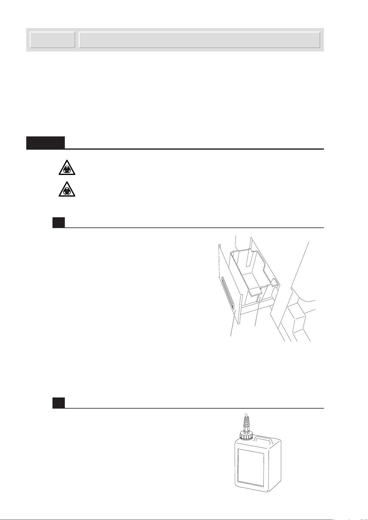
2-12
AX-4030
AUTION MAX AX-4030 OPERATING MANUAL
Waste box
Waste box tray
Drain bottle
Preparation for Measurement2.3
This section describes the tasks you should carry out on a daily basis before testing samples, which
include checking wastes and consumables, turning on the power, assigning the feeders to the item
racks, and preparing test strips and samples.
REFERENCE: Purchase the test strips specified for the instrument because the strips are not
supplied with the instrument.
2.3.1 Checking Wastes and Consumables
Wear protective gloves to prevent exposure to pathogenic microbes.
Discard liquid waste, test strips, and protective gloves in accordance with
local regulations for biohazardous waste.
1 Check for used test strips.
1 Pull out the waste tray to check if there are any used
test strips in it.
• Discard the used strips, if there are any.
• See “4.2.1 Cleaning the Waste Box” on page 4-3.
NOTE: Before pushing in the waste box, ensure
the box is correctly sitting on the waste box tray.
Incorrect installation of the waste box may cause
test strips to be scattered inside the instrument or
clog the test strip path.
NOTE: If test strips are scattered inside the
instrument due to the waste box being detached,
make sure the instrument is on standby, and
remove the strips with tweezers. Wipe the location
where the strips were present using a cloth
moistened with alcohol. Then, install the waste
box correctly.
2 Check for liquid waste.
1 Check if there is any liquid waste in the drain bottle.
• Discard the liquid waste, if there is any.
• See “4.2.2 Discarding Liquid Waste from the Drain
Bottle” on page 4-5.
Page 70
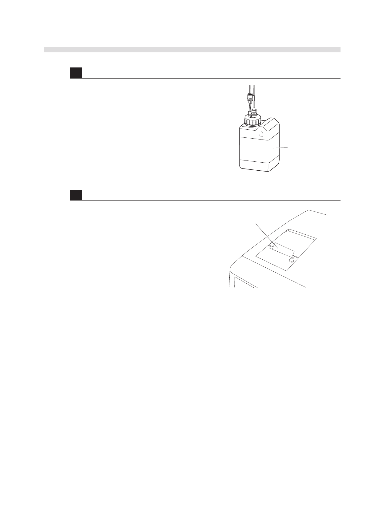
3 Check the washing solution.
Washing solution bottle
Thermal printer paper
1 Check the washing solution bottle to see if it
contains a sufficient volume of solution.
• If the solution is getting low, discard the remaining
solution, and transfer newly prepared solution to the
bottle.
• See “4.3.1 Replacing the Washing Solution” on
page 4-15.
4 Check the thermal printer paper.
AUTION MAX AX-4030 OPERATING MANUAL
1 Check for two red lines appearing on both edges of
the thermal printer paper.
• If red lines are found, replace the paper roll with a
new one.
• See “4.3.2 Replacing the Thermal Printer Paper”
on page 4-17.
AX-4030
2-13
Page 71
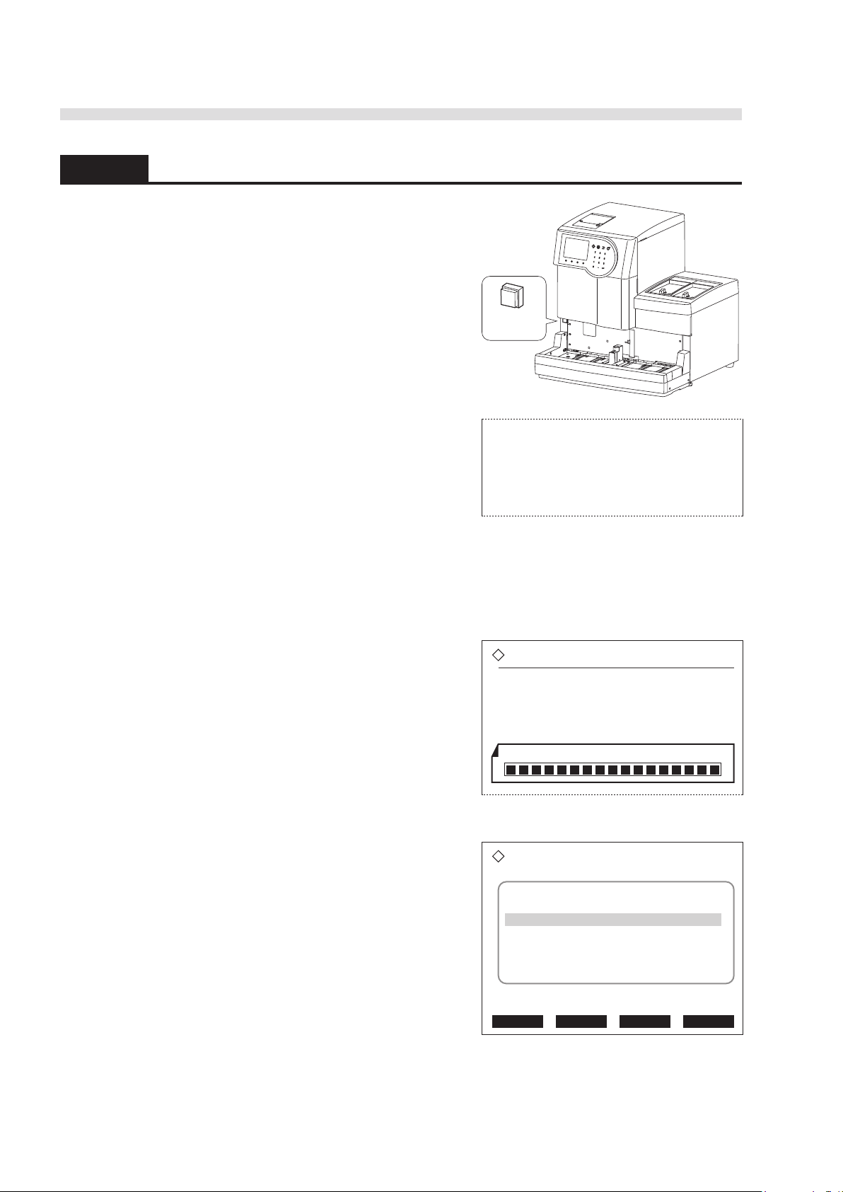
AUTION MAX AX-4030 OPERATING MANUAL
Standby
switch
Please wait...
AX-4030 V1.00
Startup
Initializing...
Please wait...
Ready for measurement
2006-01-09 10:00
Measurement start No.
0001
Test strips in feeder 1
1: 9EB
Test strips in feeder 2
2: 9EB
Menu Meas No. Strip S.G. Cal
Standby screen
2.3.2 Turning On the Power
1 Press the standby switch on the left side of the front
panel.
• The standby switch will light green.
• The message “Please wait...” will appear for a
maximum of 20 seconds, followed by the product
name and program version for about 2 seconds.
NOTE: If the initial memory check detects a
problem, the instrument will inform you of it by
indicating an appropriate warning (W), error (E),
or trouble (T) code before displaying the program
version. For more information, see Chapter 5,
“Troubleshooting”.
• The instrument will read the parameter settings, and
then initialize the hardware.
• Warm-up will complete in 2 minutes and the
standby screen shown at right will appear. You
will see the current date and time, the initial
measurement start number (0001), and the current
test strip settings.
2-14
AX-4030
D
Page 72
AUTION MAX AX-4030 OPERATING MANUAL
REFERENCE: Measurement-related parameters
The instrument provides the parameters related to measurement operation listed below.
Default settings have been made when shipped from the factory, and you can change the
settings as you need. A list of current settings can be printed out from the printer (see “3.5.3
Printing the Current Parameter Settings” on page 3-25).
Parameters Descriptions Default Page(s)
Use of printer Enables or disables the built-in printer.
Use of external output Enables or disables the external output. Not use
Result format Selects the result format for normal, STAT, and
control measurements between “semiquantitative”
and “reflectivity” respectively.
Measurement start
number assignment
Measurement number
assignment
Determines whether sequential measurement
numbers are assigned through batches, or the
measurement number is reset at the beginning of
each batch.
Determines whether measurement numbers
are assigned to samples or to all of the ports
regardless of whether the ports have samples or
not.
Use 3-18
3-20
Semiquantitative 3-4
Continue from
previous batch
Assign to
samples
3-6
3-6
AX-4030
2-15
Page 73
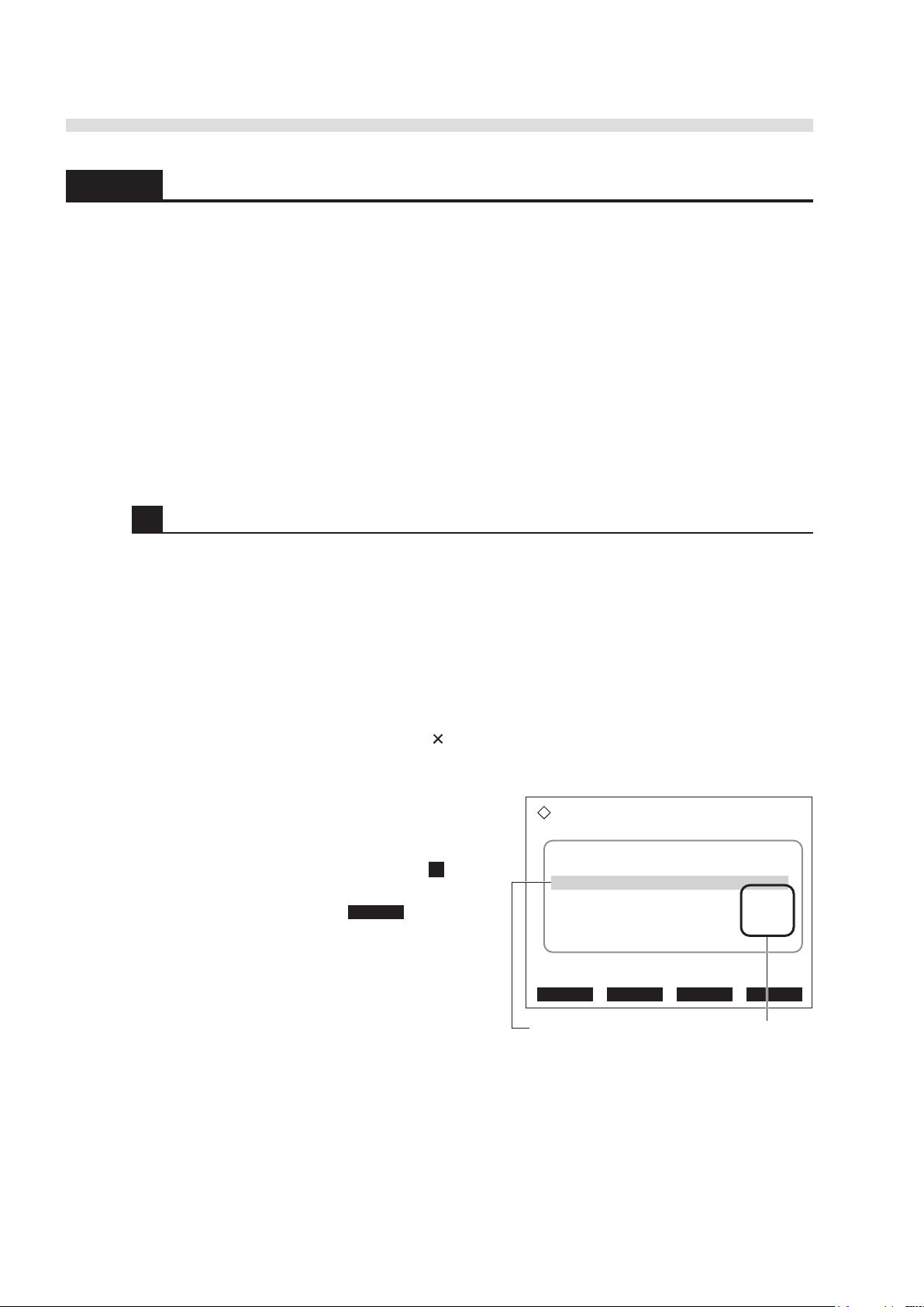
AUTION MAX AX-4030 OPERATING MANUAL
Ready for measurement
2006-01-09 10:00
Measurement start No.
0001
Test strips in feeder 1
1: 9EB
Test strips in feeder 2
2: 9EB
Menu Meas No. Strip S.G. Cal
Type of test strips
Main feeder (light blue background)
2.3.3 Loading Test Strips into the Feeders
On the standby screen, select the main feeder and the types of test strips to be used. Then, load the
correct test strips into the feeders.
IMPORTANT: Do not use the test strips beyond the expiration date or test strips having
a discolored pad area even if they are within the expiration date. Carefully read the
package inserts of the test strips before use, and observe the instructions.
NOTE: Take as many test strips as you need out of the bottles and load them into the feeders
just before testing. Each feeder can contain up to 200 test strips (equivalent to 2 bottles), but
the quality of the strips is assured only for three days. Test strips absorb moisture in the air,
which may alter their quality and produce incorrect results. The test strip bottles should be
securely capped immediately after taking out the strips.
1 Setting the test strips and main feeder by key operation.
Set the types of test strips to be loaded into the feeders, and select the main feeder between feeder 1
or 2.
REFERENCE: When to select the “main feeder”
You can select either feeder 1 or 2 as the main feeder usually. However, you should explicitly
specify the main feeder to use the sample racks listed below. These racks always use the test
strips in the feeder specified as the main feeder.
■ Start rack
■ Normal racks (optional)
■ Item racks whose rack IDs are set to [ ] on the [Rack assignment for test strip] screen.
1 On the standby screen, check the current settings
for the type of test strips and the main feeder (in
light blue background).
• If you use the current settings, go to step 2 .
2 To change the settings, press Strip .
• The [Test strip setup] screen will appear.
2-16
AX-4030
B
Page 74
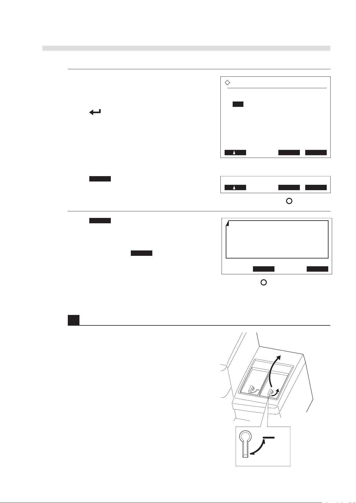
3 Below [Test strips in feeder 1] and [Test strips in
Test strip setup
Test strips in feeder 1
[9EB ]
Test strips in feeder 2
[9EB ]
Main feeder
[1]
OK Cancel
OK Cancel
Test strip setup
Test strips in feeder 1
[10EA]
Test strips in feeder 2
[9UB ]
Main feeder
[1]
OK Cancel
Save setting changes?
Open
Close
(a)
(b)
feeder 2], select the type of test strips to be loaded
into each feeder.
• Press the hyphen key to change the options.
• Press to move the cursor down.
4 Below [Main feeder], select the feeder you want to
use as the main feeder.
• Press the hyphen key to switch between feeders 1
and 2.
5 Press OK .
• A message window will open to ask if you want to
save your settings.
AUTION MAX AX-4030 OPERATING MANUAL
6 Press OK to save your changes.
• The standby screen will appear with the new
settings displayed.
REFERENCE: Press Cancel to abort your changes
and return to the standby screen.
IMPORTANT: Keep the instrument on while
saving the settings.
2 Attach a desiccant bag to the feeder cover.
1 Turn the locking lever (a) to unlock the feeder
cover, and open the cover (b).
D
AX-4030
2-17
Page 75
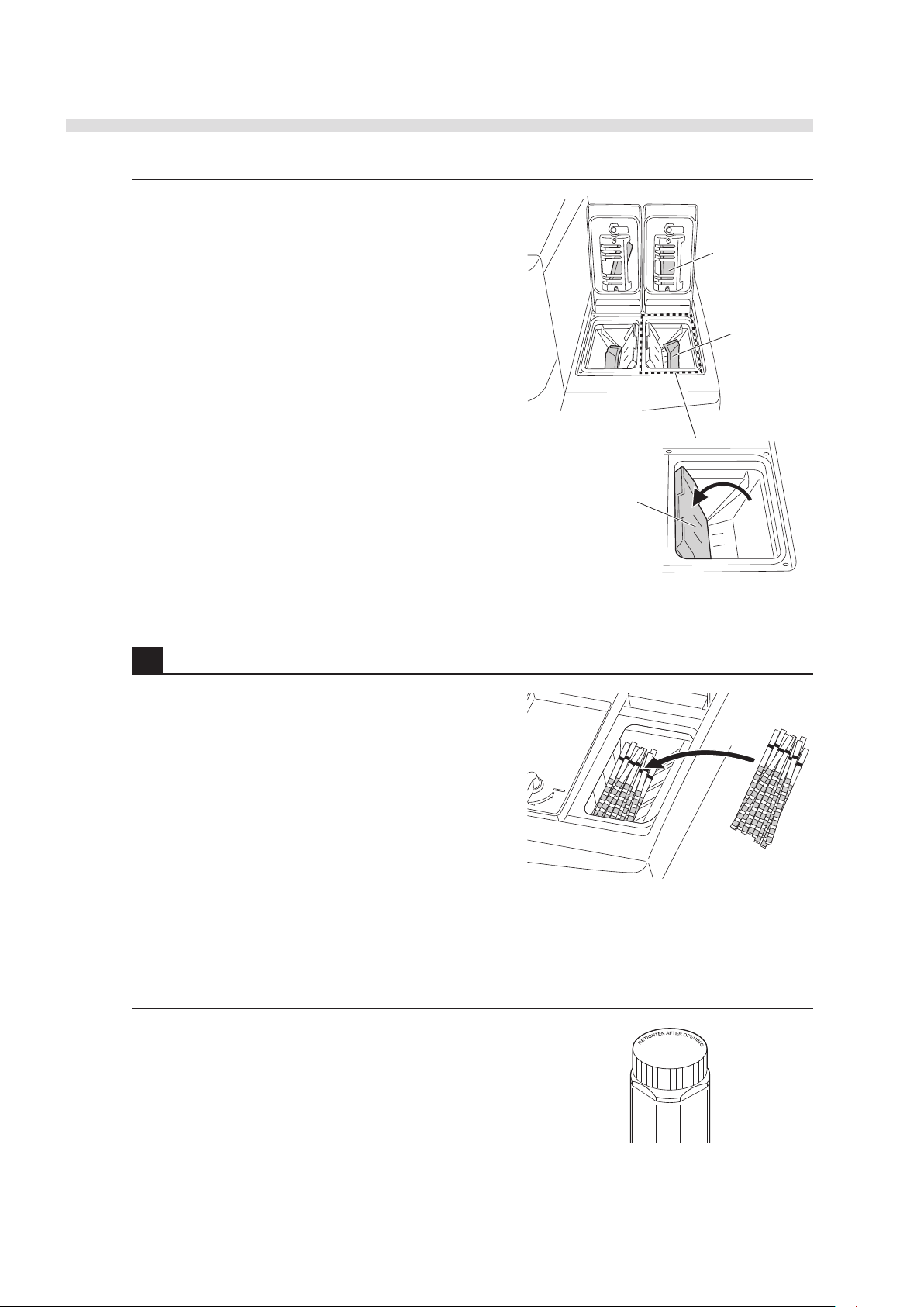
2-18
AX-4030
AUTION MAX AX-4030 OPERATING MANUAL
Desiccant bag
(When loading
200 strips)
Desiccant bag
(Always required)
Tilt side panel of
storage section.
2
2 Tilt the side panel of the storage section in the
direction of the arrow.
3 Take out a desiccant bag from the test strip bottle
and attach it to the feeder cover.
• For loading 100 test strips, attach a desiccant bag on
the side panel of the storage section. If loading 200
test strips, attach one bag on the back of the cover,
and another bag on the side panel of the storage
section.
4 Place the side panel as before.
REFERENCE: Replace the desiccant bags on
the feeders each time a new test strip bottle is
opened.
3 Load the test strips into the feeders.
1 Take out as many test strips as you need from the
bottle, and load them into the feeder.
• Level test strips into even piles.
IMPORTANT: Do not touch the pad area on
the test strips. Contact can cause sebum to
adhere to the surface, whereby producing
incorrect results.
NOTE: Place the test strips with the black marker to
the back side of the feeder (see the figure at right).
2 Close the feeder cover and turn the locking lever clockwise to lock it.
3 Cap the test strip bottle.
IMPORTANT: Without desiccant bags, the test
strips can absorb moisture in the air. Cap the
bottle securely to avoid deterioration of the
strips.
Page 76
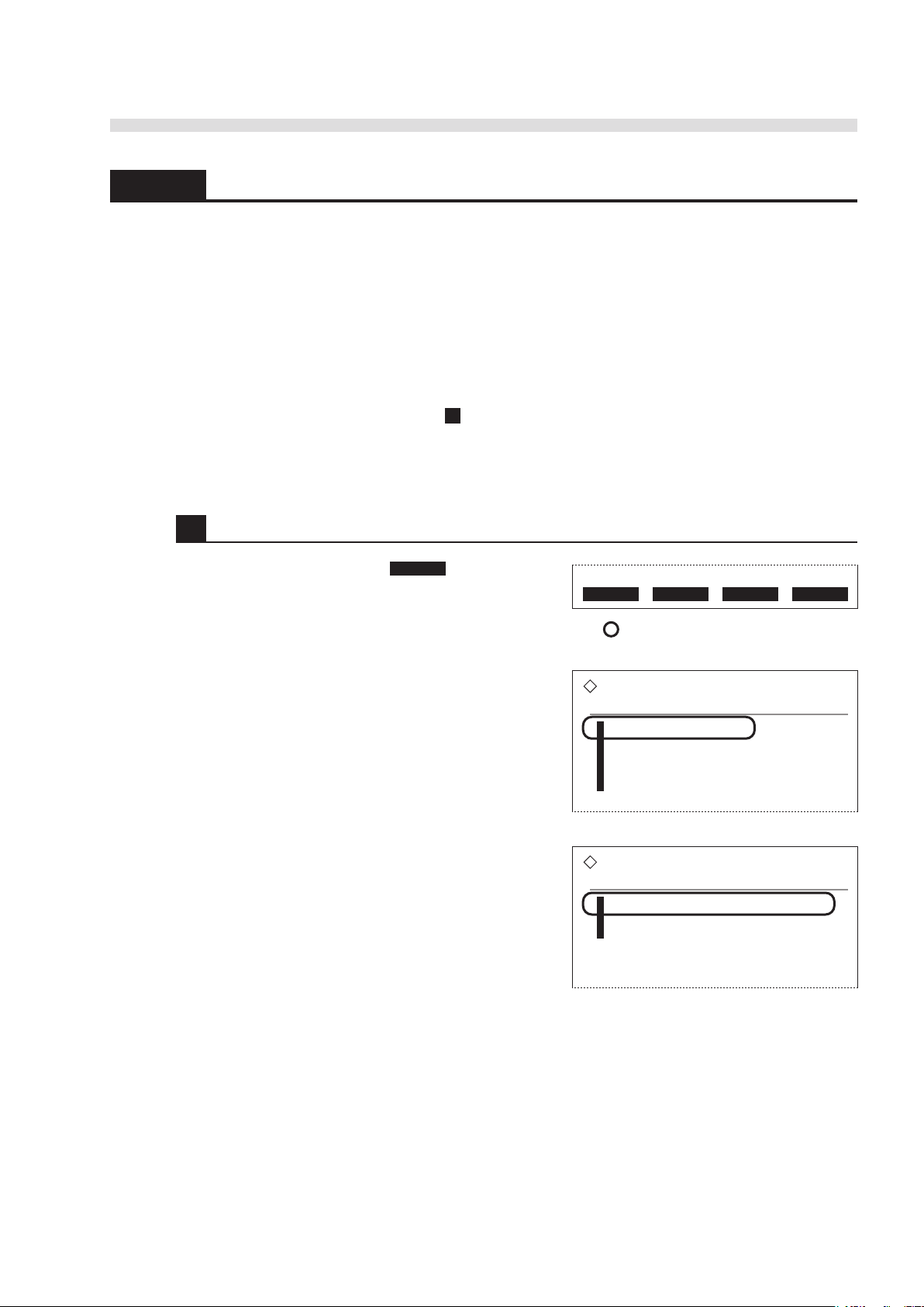
AUTION MAX AX-4030 OPERATING MANUAL
Menu Meas No. Strip S.G. Cal
Main menu
(0000) 2006-01-09 10:10
1 Parameter settings
2 Results
3 Initial settings
4 Print
5 Maintenance
Parameter settings
(1000) 2006-01-09 10:10
1 Rack assignment for test strip
2 Results display format
3 Measurement No. setup
2.3.4 Assigning the Type of Test Strips to the Item Racks
Assign a feeder (1, 2, or main) to each item rack (rack ID #01 to #10) used for normal
measurement. This allows the instrument to automatically eject appropriate test strips from the
assigned feeder for measuring samples in the item rack. For example, you can set it so that samples
in the rack #01 are measured with the test strips in feeder 1. Make correct settings to successfully
use the item racks. For more information about the item racks, see “Sample Racks” in “2.1.4
Sample Containers and Sample Racks” on page 2-7.
NOTE: In the following procedure, what you actually assign to the item racks are feeders (1, 2,
or main), not the type of test strips. If you want to change the type of test strips to load into the
feeder, see the instructions in step 1 in “2.3.3 Loading Test Strips into the Feeders” on page
2-16.
1 Access the setup screen.
1 On the standby screen, press Menu to go to the
[Main menu] screen.
2 Press 1 to go to the [Parameter settings] screen.
3 Press 1 to go to the [Rack assignment for test strip]
screen.
AX-4030
2-19
Page 77
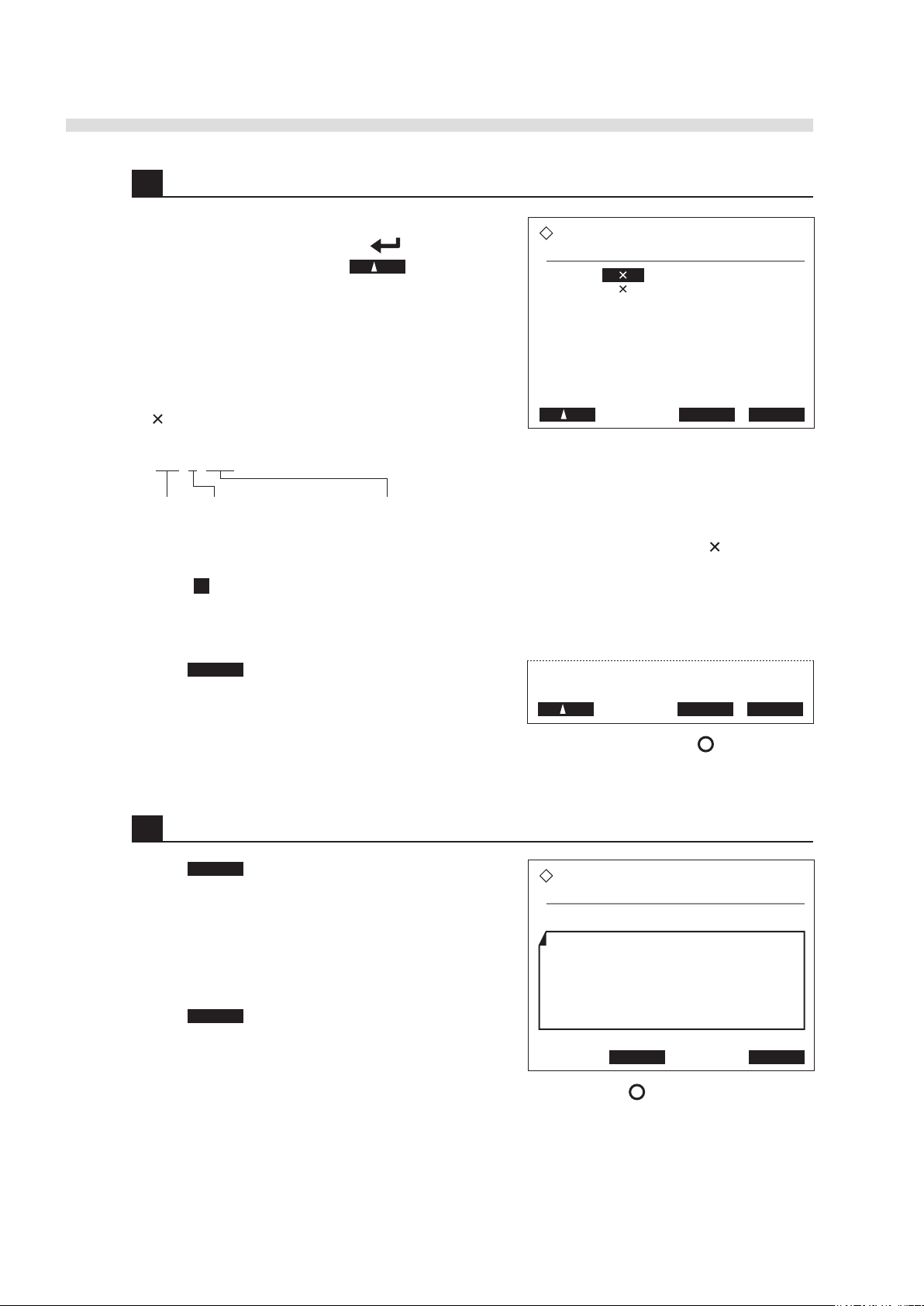
AUTION MAX AX-4030 OPERATING MANUAL
Rack assignment for test strip
(1100) 2006-01-09 10:12
#01 [ × ]
#02 [ × ]
#03 [1:9EB ]
#04 [1:9EB ]
#05 [1:9EB ]
#06 [1:9EB ]
#07 [2:9EB ]
#08 [2:9EB ]
#09 [2:9EB ]
#10 [2:9EB ]
OK Cancel
Rack ID Feeder No. (selectable here) Test strips set for the feeder
#01 [1:9EB ]
Rack assignment for test strip
(1100) 2006-01-09 10:12
#01 [ × ]
#02 [ × ]
#03 [1:9EB ]
#04 [1:9EB ]
#05 [1:9EB ]
#06 [1:9EB ]
#07 [2:9EB ]
#08 [2:9EB ]
#09 [2:9EB ]
#10 [2:9EB ]
OK Cancel
Rack assignment for test strip
(1100) 2006-01-09 10:12
#01 [1:9EB ]
#02 [2:9EB ]
#03 [1:9EB ]
#04 [1:9EB ]
#05 [1:9EB ]
#06 [1:9EB ]
Save setting changes?
OK Cancel
Save setting changes?
2 Assign the types of test strips to rack IDs.
1 Choose a rack ID, from #01 to #10.
• To move the cursor down, press .
• To move the cursor up, press .
2 Choose a feeder number.
• To change options, press the hyphen key.
• Samples in the item racks will be measured with the
test strips in the feeder specified here.
• [ ] represents the main feeder.
REFERENCE: You can select one among feeder 1, feeder 2, or the main feeder ( ) for each
item rack. The type of test strips shown at the right of the feeder number is the one specified in
step 1 in “2.3.3 Loading Test Strips into the Feeders” on page 2-16. The test strips and main
feeder settings cannot be changed here.
3 Press OK .
• You will be asked to save the changes.
3 Save the changes.
1 Press OK to save the changes and return to the
[Parameter settings] screen.
NOTE: Keep the power on while saving the
settings.
2 Press Go back twice to go back to the standby
screen.
2-20
AX-4030
B
Page 78
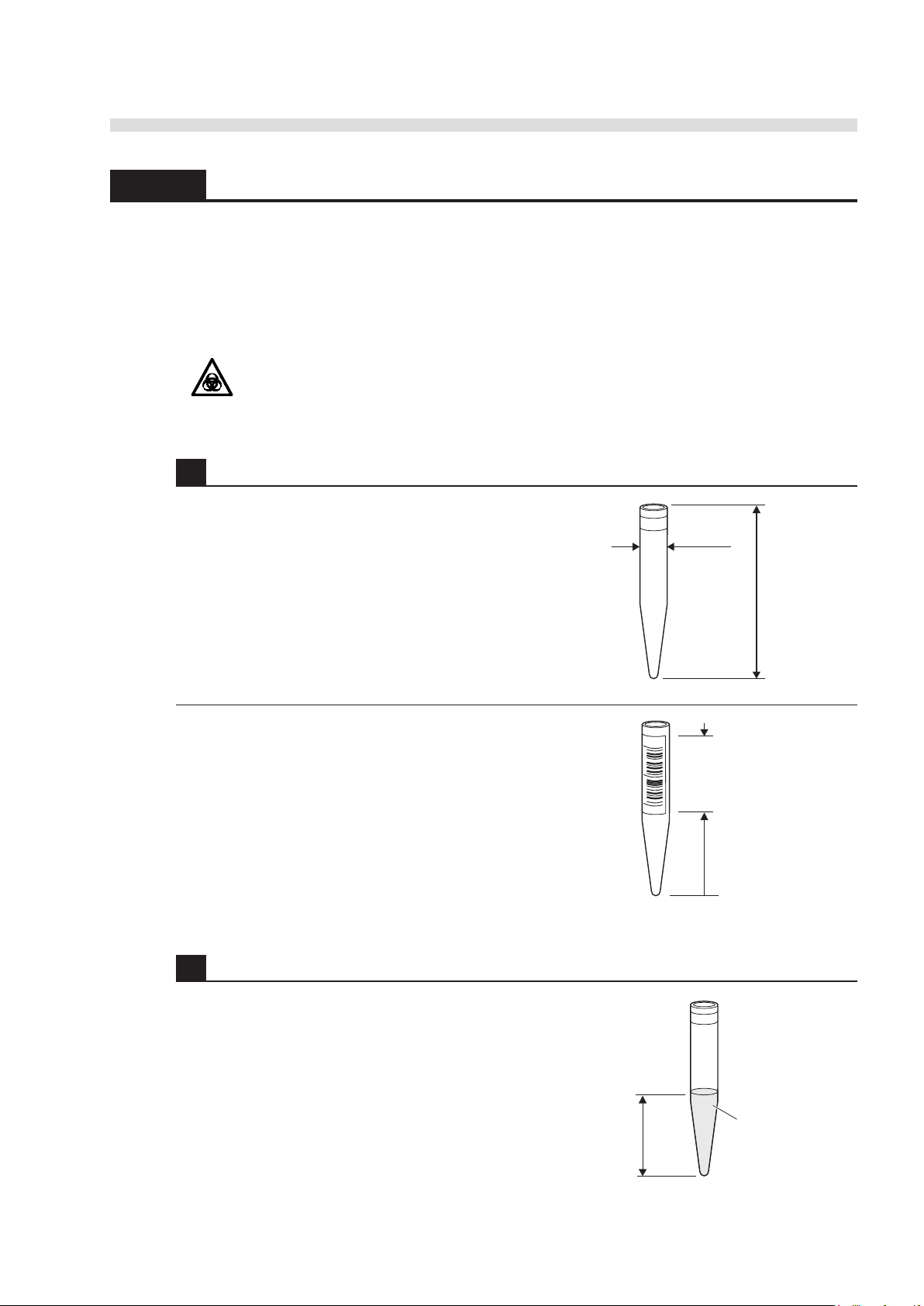
2.3.5 Preparing Samples
105 mm
15.8 mm
Min. 30 mm
Min. 5 mm
Min. 2 mL
Min. 40 mm
Transfer samples into sample tubes, load the tubes into the sample racks, and place the sample
racks in the sampler of the instrument. See “2.2.2 Handling Samples” on page 2-10 to learn
precautions on samples.
Prepare: Sample tubes, item racks, and protective gloves
Wear protective gloves to prevent exposure to pathogenic microbes.
1 Prepare sample tubes.
AUTION MAX AX-4030 OPERATING MANUAL
1 Prepare the sample tubes that comply with the
standards shown at right.
REFERENCE: To have the built-in barcode reader
read barcodes successfully, label the tubes as
shown at right.
AX-4030
2 Pour samples into sample tubes.
1 Fill a sample tube with at least 2 mL of sample.
Ensure the sample level is at least 40 mm above the
bottom of the tube.
IMPORTANT: An insufficient volume of sample
may produce incorrect results.
2-21
Page 79
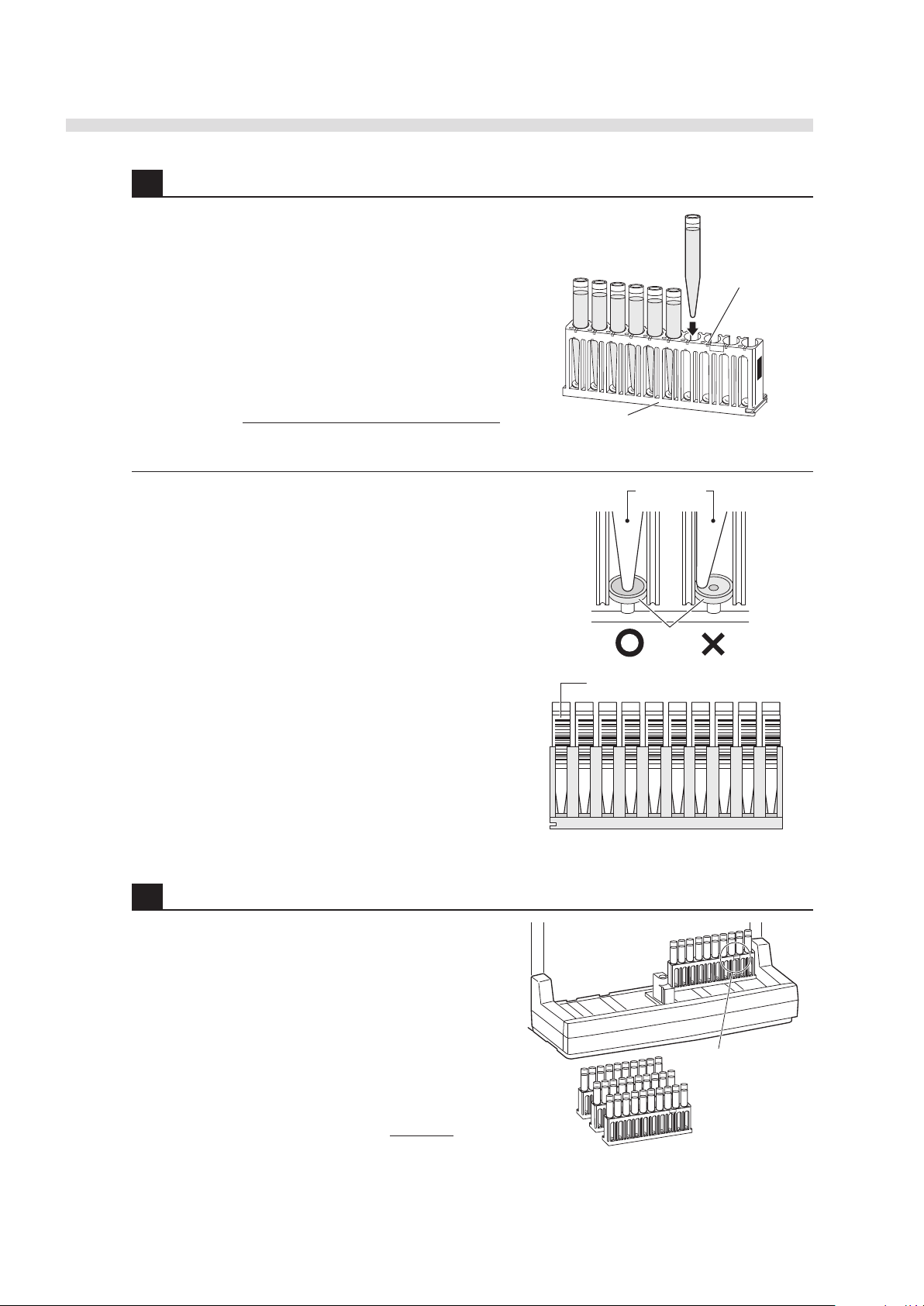
AUTION MAX AX-4030 OPERATING MANUAL
Gray adapters
Item rack
Rubber
cushions
Sample tubes
Barcode label
Rear of sample rack
Marker
3 Load the sample tubes into the sample racks.
1 Place the sample tubes into the ports of the item
rack.
• Use an item rack (rack ID #01 to #10) assigned to
the feeder that contains the test strips to be used for
measurement.
• Optional normal racks can also be used as an
alternative.
NOTE: If the rack transportation method is set to
“loop”, load the first 10 samples into the start rack.
Starting a batch with another type of rack may
cause double measurement on samples. See page 2-6.
NOTE: Fit the bottom of the sample tubes into the
recessed portion of the rubber cushions so that
the tubes stand straight. Placing tubes out of
position may cause sample aspiration to fail and
could even damage the nozzle.
REFERENCE: To have the built-in barcode reader
read barcodes successfully, labels on the tubes
must be facing to the rear side of the sample rack.
4 Load the sample racks into the sampler.
1 Hold the sample rack with the marker facing you
and place it on the loading side of the sampler.
• First, place the rack at the frontward of the loading
side, fit the recesses at the lower right of the rack
into the guides inside the sampler, and slide the rack
backward.
• The loading side can contain up to 5 racks.
REFERENCE: When the rack transportation
method is set to “loop”, place the start rack at the
beginning. The unloading side of the sampler can
also be used to load racks (up to 5 racks). See page 2-6.
2-22
NOTE: If a sample spills on the sampler, immediately wipe it off. A crystallized sample may
hinder smooth transportation of the sample racks, and consequently cause trouble.
AX-4030
D
Page 80
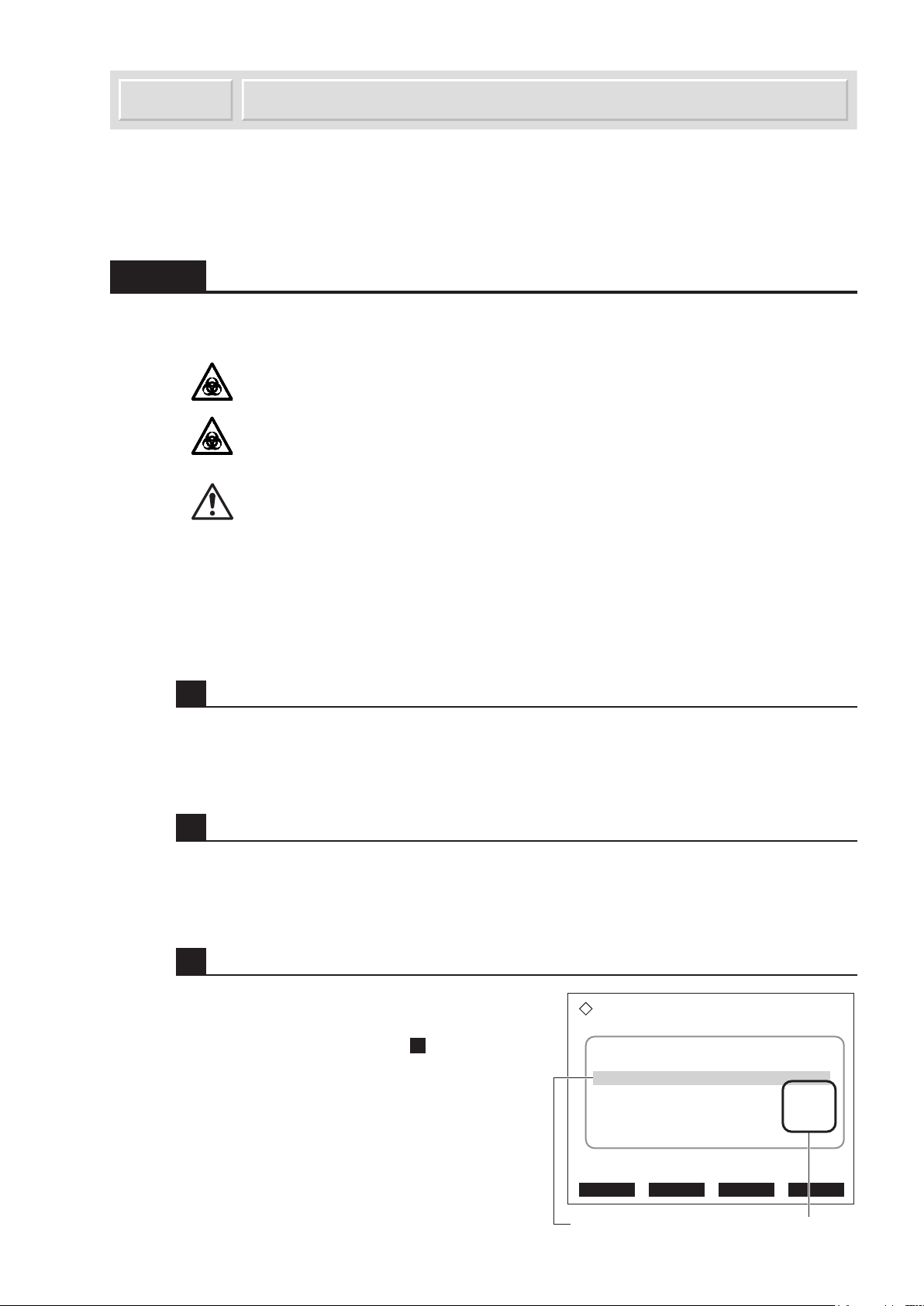
AUTION MAX AX-4030 OPERATING MANUAL
Ready for measurement
2006-01-09 11:00
Measurement start No.
0001
Test strips in feeder 1
1: 9EB
Test strips in feeder 2
2: 9EB
Menu Meas No. Strip S.G. Cal
Type of test strips
Main feeder (light blue background)
Measurement Operations2.4
This section gives instructions for measuring samples continuously (normal measurement), and
measuring higher priority samples (port/rack STAT measurement).
2.4.1 Normal Measurement: Measuring Samples Continuously
Prepare: Item racks or optional normal racks, sample tubes, and protective gloves
Wear protective gloves to prevent exposure to pathogenic microbes.
Discard used samples, test strips and protective gloves in accordance with
local regulations for biohazardous waste.
Safety devices may trip and automatically stop operation of the instrument
if the front cover, maintenance cover, feeder protective cover, or side
cover is opened. Do not open the covers unless required. In the case
of an automatic stop, some aspirated samples may not be measured
successfully. Check the printed results reports thoroughly, and test the
samples again if necessary.
1 Perform S.G. calibration.
Calibrate the instrument using low and high specific gravity standard solutions once a month. For
instructions, see “2.5 S.G. Calibration” on page 2-34.
2 Load test strips into the feeders.
1 Load the test strips into the feeders.
• See “2.3.3 Loading Test Strips into the Feeders” on page 2-16.
3 Check the settings of the test strips and feeders.
1 On the standby screen, check if the settings of
the test strips and main feeder are correct.
• To change the settings, see step 1 in “2.3.3
Loading Test Strips into the Feeders” on page
2-16.
• For information on the main feeder, see
“REFERENCE: When to select the main feeder”
on page 2-16.
F
AX-4030
2-23
Page 81
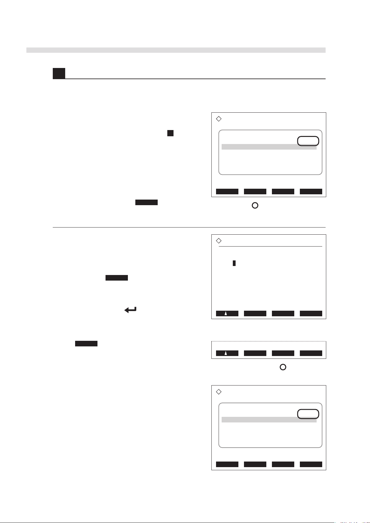
2-24
AX-4030
AUTION MAX AX-4030 OPERATING MANUAL
B
Ready for measurement
2006-01-09 11:00
Measurement start No.
0001
Test strips in feeder 1
1: 9EB
Test strips in feeder 2
2: 9EB
Menu Meas No. Strip S.G. Cal
Measurement start No.
Normal measurement
<0150>
Control measurement
<0001>
BS OK Cancel
BS OK Cancel
Ready for measurement
2006-01-09 11:00
Measurement start No.
0150
Test strips in feeder 1
1: 9EB
Test strips in feeder 2
2: 9EB
Menu Meas No. Strip S.G. Cal
4 Set the measurement start number.
For information on the measurement start number, see “Measurement number” in “2.1.3
Measurement Terminology” on page 2-4.
1 On the standby screen, check the measurement start
number.
• To use the current number, skip to step 5 .
2 To set a new number, press Meas No. .
• The [Measurement start No.] screen will appear.
3 Below [Normal measurement], enter a number from
0000 to 9999, using the numeric keys (0 to 9).
REFERENCE: For example, to enter “0150”,
press 0, 1, 5, and 0 in that order. To correct the
number, press BS to delete the digits one by
one, and enter a new number.
REFERENCE: If the cursor is placed below [Control
measurement], press to move up to the
[Normal measurement] entry field.
4 Press OK to save your changes.
• The standby screen will appear again with a new
measurement start number.
Page 82
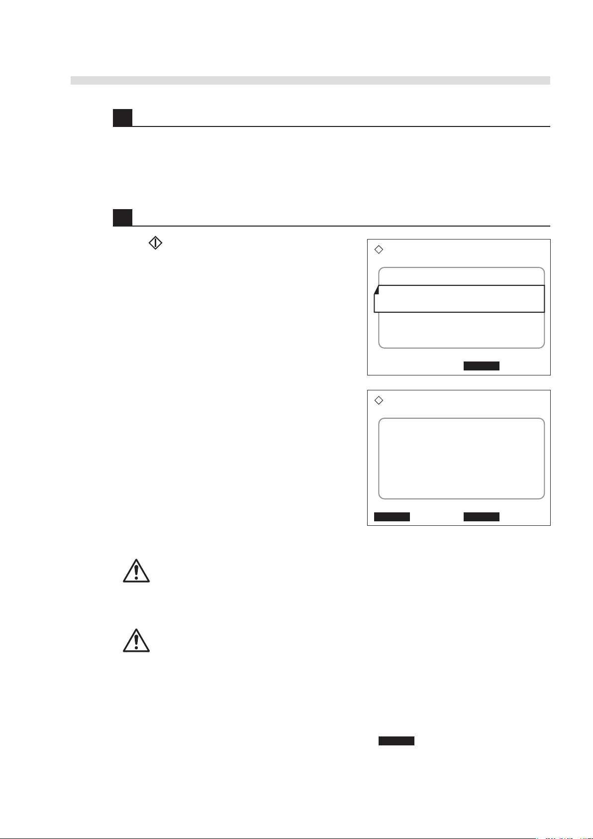
AUTION MAX AX-4030 OPERATING MANUAL
Measuring...
2006-01-09 11:15
Port No.
0001
Measurement No.
0150
ID
----------------- Test strip type
1: 9EB
Stop
Waiting for rack...
Measuring...
2006-01-09 11:15
Port No.
0001
Measurement No.
0150
ID
----------------- Test strip type
1: 9EB
Results Stop
5 Prepare samples.
1 Pour samples into sample tubes and load them into the sampler.
• See “2.3.5 Preparing Samples” on page 2-21.
6 Start the normal measurement.
1 Press to start.
• The first sample rack will be transported to the
aspiration position while “Waiting for rack…” is
displayed.
• The nozzle will come down to aspirate the
sample from the first sample tube, and then the
measurement operation will take place.
• When the result of the sample is obtained, it is
reported on a printout. See “2.8.2 Printed Results
Report” on page 2-50.
• The following samples are processed in the same
way.
Do not touch the sample rack being grabbed at the rear of the sampler. The
rack can move suddenly, which is very dangerous. When adding sample
racks to the sampler during measurement, keep hands away from the rack
at the rear and place new racks at the front.
The test strip storage section may be driving while measurement is in
progress. Do not touch inside the storage section directly with hands when
adding test strips in the feeder. Contact with the drive mechanism may
cause injury.
B
AX-4030
REFERENCE: To add test strips during measurement
Open the feeder cover. You will see “W006: Close the feeder cover.” on the screen. Add new
test strips in the feeder, close the cover, and then press OK to clear the warning.
2-25
Page 83
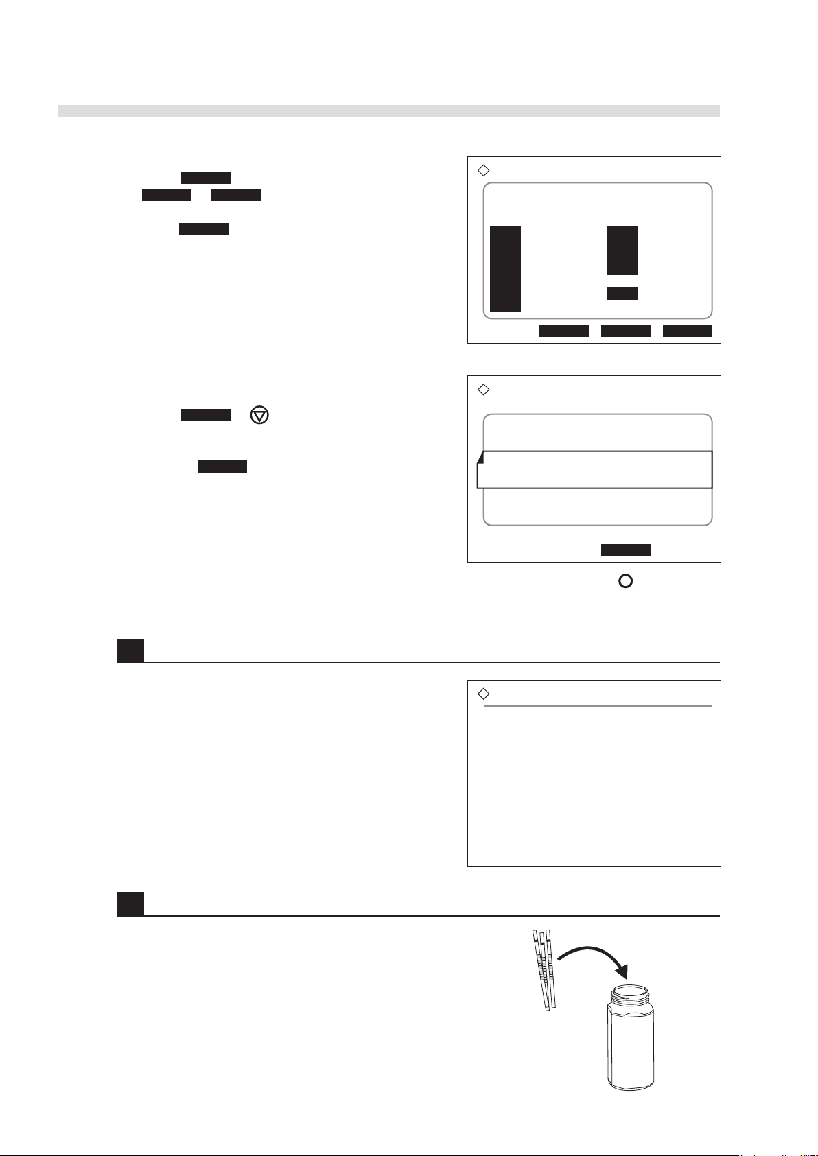
AUTION MAX AX-4030 OPERATING MANUAL
View
Date 2006-01-09 11:16 Kind NORMAL
No. 0150 Po. 001-05 Strip 1: 9EB
ID 000000000000000000
GLU - *PRO 4+
BIL - URO NORMAL
PH 7.0 !BLD + *KET 4+ NIT LEU -
TURB - S.G. 1.000
COLOR LIGHT YELLOW
<<<<<<<< >>>>>>>> Go back
Measuring...
2006-01-09 11:20
Port No.
0021
Measurement No.
0010
ID
----------------- Test strip type
1: 9EB
Start
Suspended
Measurement operations ending.
Please wait...…
REFERENCE: To view results
Press Results to view the latest result. Pressing
<<<<<<<< or >>>>>>>> can view the previous or next
result. To return to the [Measuring...] screen,
press Go back .
REFERENCE: To suspend measurement in
progress
Press Stop or . The instrument will
display “Suspended”, and stop the measurement
operation. You can resume the operation by
pressing Start within a minute. If more than
1 minute elapses, the instrument will proceed
with end process and can no longer resume the
suspended operation. Depending on the timing
the stop key is pressed, some already-aspirated
samples may not be measured successfully. View
the printed reports to check if correct results are
obtained.
7 When measurements of all samples are completed…
• The message “Measurement operations ending”
will appear after the entire batch of samples has
been measured. The instrument will proceed with
flow line flushing and other end processes.
• When the end processes are completed, the standby
screen will appear again.
1 Take out the sample racks from the sampler.
8 At the end of the day…
1 Take the test strips out of the feeder, and put them
2-26
back in the bottle.
2 Dispose of liquid waste and used test strips.
• See “4.2.1 Cleaning the Waste Box” on page 4-3,
and “4.2.2 Discarding Liquid Waste from the Drain
Bottle” on page 4-5.
3 Press the standby switch to power off.
AX-4030
F
Page 84
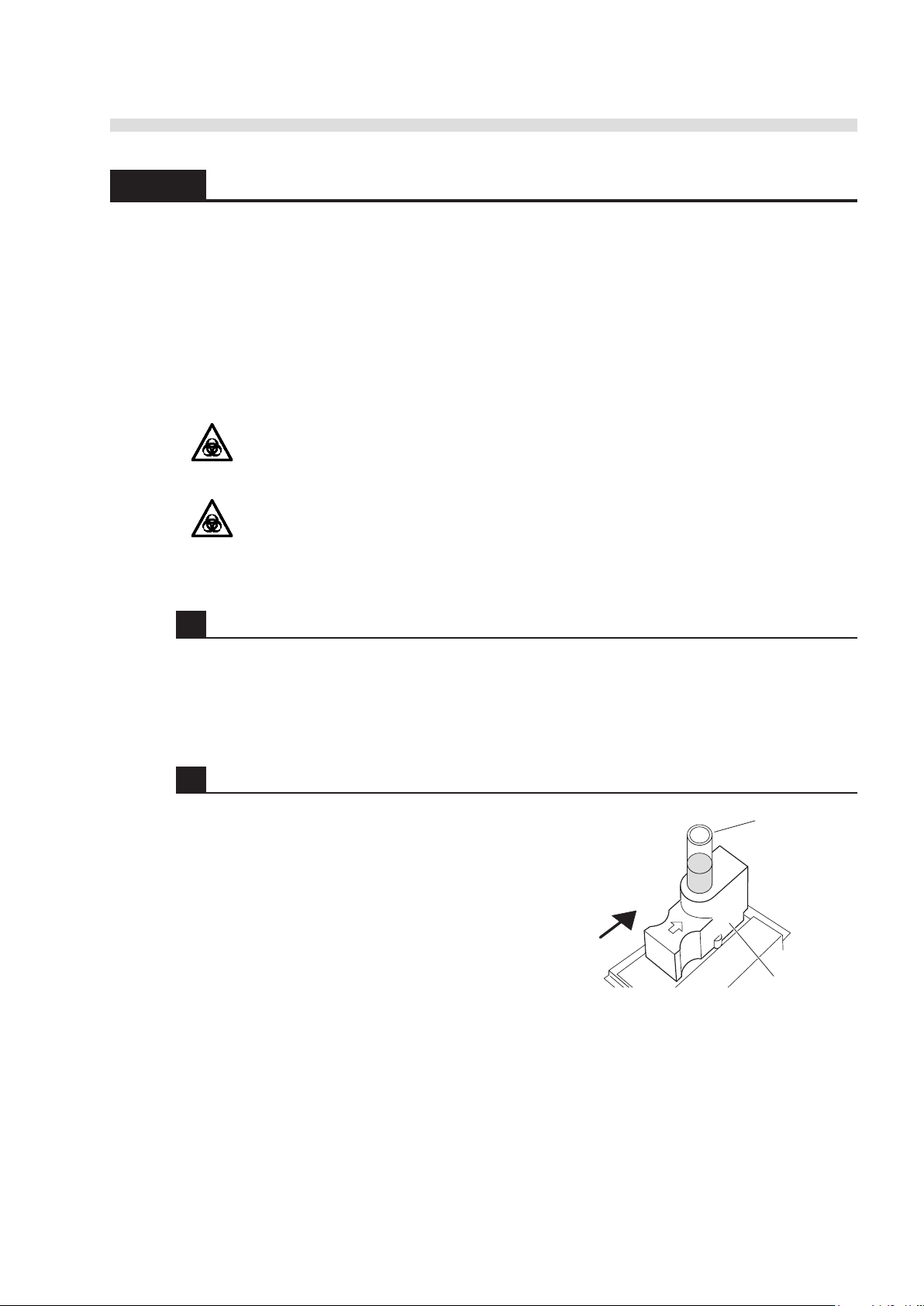
AUTION MAX AX-4030 OPERATING MANUAL
PUSH
STAT port
Sample
2.4.2 Port STAT Measurement: Measuring a Higher Priority Sample
Port STAT measurement is for measuring a single sample loaded into the STAT port located at the
center of the sampler. You may use the STAT port when you have only one sample to measure, or
when you are asked to measure a new sample urgently while normal measurement is in progress.
If you want to interrupt normal measurement to quickly measure additional two or more samples,
use rack STAT measurement (see “2.4.3 Rack STAT Measurement: Measuring Higher Priority
Samples” on page 2-31).
Prepare: Sample tube and protective gloves
Wear protective gloves to prevent exposure to pathogenic microbes.
Discard used samples, test strips and protective gloves in accordance with
local regulations for biohazardous waste.
1 Prepare a sample for STAT measurement.
1 Pour the sample for STAT measurement in a sample tube.
• See “2.3.5 Preparing Samples” on page 2-21.
2 Load the sample tube into the STAT port.
1 Place the sample tube straight into the STAT port.
2 While pressing the “PUSH” mark, slide the STAT
port backward and push it in place.
3 Gently pull the STAT port toward you to ensure the
port is locked.
AX-4030
2-27
Page 85
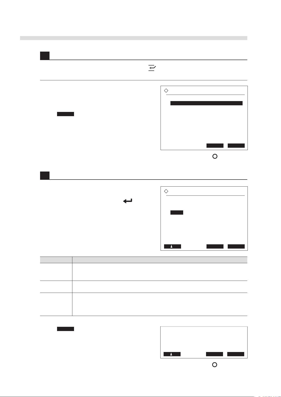
2-28
AX-4030
AUTION MAX AX-4030 OPERATING MANUAL
B
STAT reservation
Sample feeding
[Use port ]
OK Cancel
STAT reservation
Use port
Test strip
[1: 9EB]
Measurement No.
<0001>
ID
<------------------>
Place sample in STAT port.
OK Cancel
STAT reservation
Use port
Test strip
[1:10EA]
Measurement No.
<0001>
ID
<------------------>
Place sample in STAT port.
OK Cancel
3 Switch to the port STAT measurement mode.
1 During normal measurement or on standby, press to go to the [STAT reservation] screen.
2 Below [Sample feeding], choose [Use port].
• Press the hyphen key to switch between
[Use port] and [Use rack].
3 Press OK .
• The next [STAT reservation] screen will appear.
4 Set the measurement parameters.
1 Set the parameters for port STAT measurement.
• See the table below.
• To move the cursor downward, press .
Items Descriptions
Test strip Select the feeder to use for STAT measurement. Press the
feeder number. At the right of the feeder number, the type of test strips currently set for
the feeder is shown.
Measurement
No.
ID Enter the ID for the sample. An ID can be up to 18 digits long and can contain numbers,
Enter the measurement number for the sample. For example, to enter “0200”, press
0, 0 in that order.
alphabet, and special characters. For more information, see
Operations and Examples” on page 1-45. The optional hand-held barcode reader can also
be used to read the ID from the barcode labeled on the sample tube.
hyphen key to change the
“ID” in “1.7.3 Menu
0, 2,
2 Press OK .
Page 86
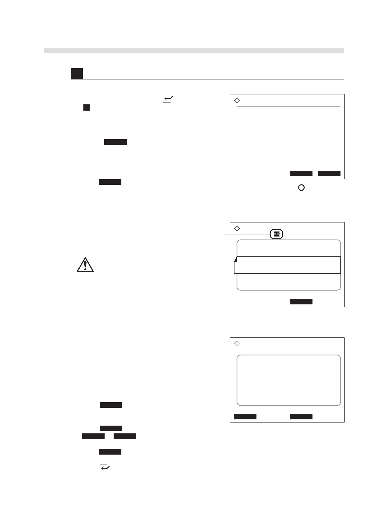
5 Start the port STAT measurement.
STAT reservation
Use port
Test strip
1: 9EB
Measurement No.
0002
ID
060108-001-00248
Start Cancel
Measuring...
2006-01-09 11:35
Port No.
0020
Measurement No.
0020
ID
----------------- Test strip type
1: 9EB
Stop
STAT reserved
STAT measurement icon blinks.
Measuring...
2006-01-09 11:36
Port No.
STAT
Measurement No.
0002
ID
060108-001-00248
Test strip type
1: 9EB
Results Stop
AUTION MAX AX-4030 OPERATING MANUAL
How the STAT measurement takes place depends on
the status of the instrument when is pressed in
step 3 .
If the instrument is on standby:
1 Check the settings on the [STAT reservation] screen,
and press Start to start measurement.
REFERENCE: Warning “W002” occurs with a beep
if the STAT port is out of the sample aspirating
position. Place the sample correctly and
press OK .
If measurement is underway:
• “STAT reserved” will appear and the STAT
measurement icon will blink to indicate STAT
measurement has been reserved.
Keep hands away from the STAT
port while the STAT measurement
icon is blinking. The aspirating
nozzle may descend into the STAT
port.
On standby
During normal measurement
• Port STAT measurement will automatically start
when aspiration of the normal measurement sample
in process is completed.
REFERENCE: The following keys are operational
during STAT measurement.
■ Press Stop to stop STAT measurement.
Normal measurement also stops if it was running.
B
AX-4030
■ Press results to view the latest result. Pressing
<<<<<<<< or >>>>>>>> can view the previous or next
result. To return to the [Measuring…] screen,
press Go back .
■ Press to make another reservation for STAT measurement.
2-29
Page 87
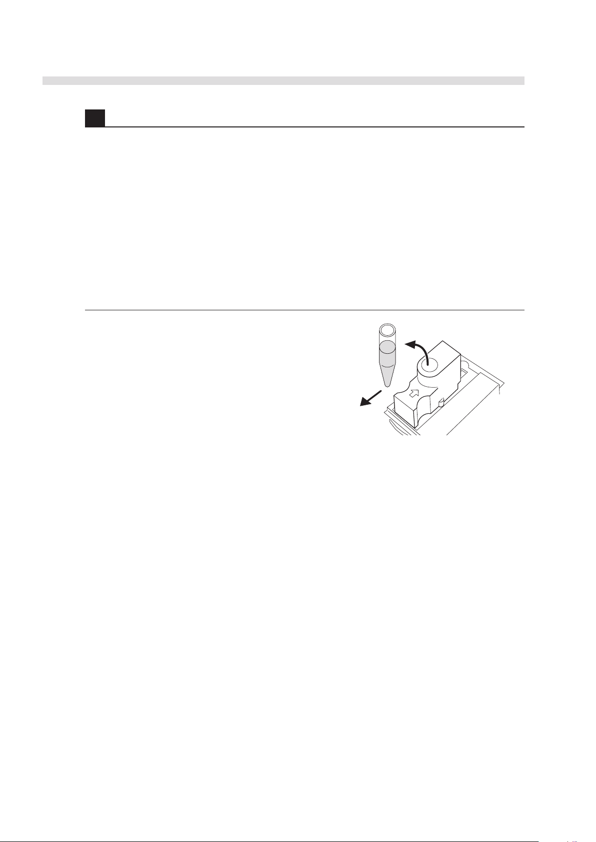
AUTION MAX AX-4030 OPERATING MANUAL
2
1
PUSH
6 When port STAT measurement is completed…
• The result of the STAT measurement will be printed.
• The instrument will then operate in a different way depending on the status before performing
STAT measurement.
If the instrument was on standby:
The display will show “
then the instrument will put itself on standby.
If measurement was underway:
The suspended normal measurement will resume.
Measurement operations ending”, the flow lines will be flushed, and
1 Press the “PUSH” mark on the STAT port
backward to unlock the stopper, and then slide the
port toward you.
2 Take the sample tube out of the STAT port.
2-30
AX-4030
Page 88
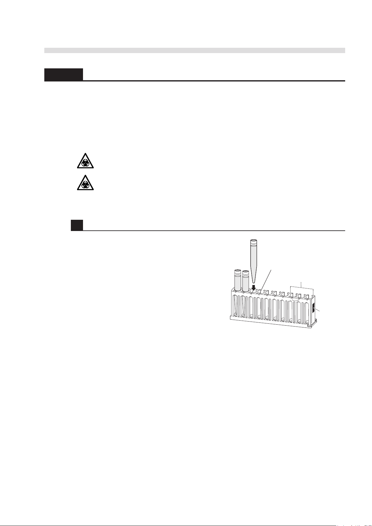
AUTION MAX AX-4030 OPERATING MANUAL
Orange adapters
Keep empty.
STAT and control rack
Black label
2.4.3 Rack STAT Measurement: Measuring Higher Priority Samples
Rack STAT measurement allows you to have up to 7 samples measured prior to the samples
waiting for normal measurement in the sampler. This is accomplished by loading the higher priority
samples into the STAT and control rack and placing the rack between the sample racks currently
loaded in the sampler. Rack STAT measurement can also be carried out during standby.
Prepare: STAT and control rack, sample tubes, and protective gloves
Wear protective gloves to prevent exposure to pathogenic microbes.
Discard used samples, test strips and protective gloves in accordance with
local regulations for biohazardous waste.
1 Prepare samples for STAT measurement.
1 Pour samples for STAT measurement in sample
tubes.
• See “2.3.5 Preparing Samples” on page 2-21.
2 Place the sample tubes straight into ports 1 to 7 with
the orange adapters of the STAT and control rack.
REFERENCE: Leave ports 8 to 10 with the dark
blue adapters empty as they are for control
measurement.
D
AX-4030
2-31
Page 89
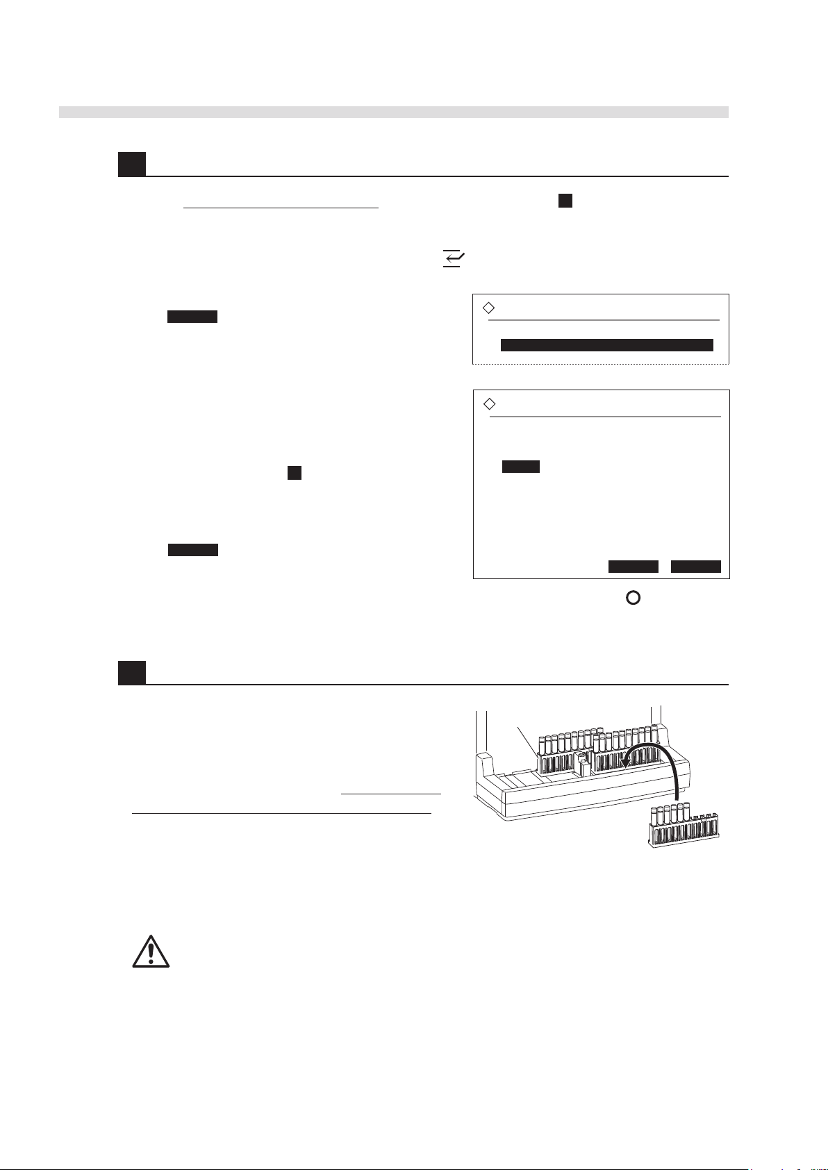
AUTION MAX AX-4030 OPERATING MANUAL
STAT reservation
Sample feeding
[Use rack ]
STAT reservation
Use rack
Test strip
[1: 9EB]
Measurement No.
<0001>
OK Cancel
Rack in aspirating
STAT and control rack
2 Set the measurement parameters.
If you use the test strips in the main feeder, skip this step and go to step 3 . The main feeder is
indicated by a light blue background on the standby screen.
1 To use the test strips in the non-main feeder, press to go to the [STAT reservation] screen.
2 Below [Sample feeding], choose [Use rack] and
press OK to go to the next screen.
3 Below [Test strip], select the feeder that contains the
test strips to use.
Below [Measurement No.], select the measurement
start number for STAT measurement.
• For instructions, see step 4 in “2.4.2 Port STAT
Measurement: Measuring a Higher Priority
Sample” on page 2-27.
4 Press OK .
3 Load the STAT and control rack into the sampler.
1 Place the STAT and control rack on the loading side
of the sampler.
• If there are some racks waiting for normal
measurement on the loading side, keep the rack at
the aspirating position (furthest from you) as it is
and slide the other racks toward you to make room
for the STAT and control rack.
• If the loading side is full with racks, remove one of
them and insert the STAT and control rack.
During normal measurement, the aspirating nozzle descends into the ports
of the rack located furthest from you. For your safety, do not move the rack
in the process of aspiration.
2-32
NOTE: If samples spill on the sampler, immediately wipe them off. Crystallized samples may
hinder smooth transportation of the sample racks, and consequently cause trouble.
AX-4030
D
Page 90
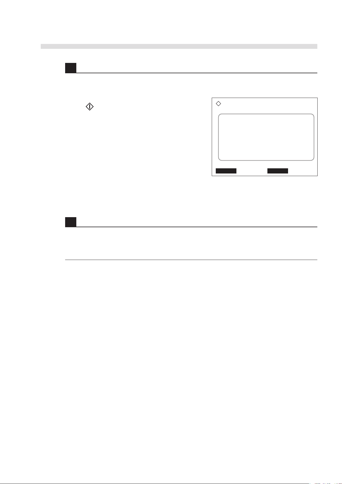
AUTION MAX AX-4030 OPERATING MANUAL
Measuring...
2006-01-09 11:45
Port No.
0001
Measurement No.
0002
ID
060108-001-00248
Test strip type
1: 9EB
Results Stop
4 Start the rack STAT measurement.
How the STAT measurement takes place depends on the status of the instrument.
If the instrument is on standby:
1 Press to measure the samples in the STAT and
control rack.
• Samples are processed in the same way as those for
normal measurement.
If measurement is underway:
• STAT measurement will start when the STAT and
control rack reaches the sample aspirating position.
Samples are processed in the same way as those for
normal measurement.
5 When rack STAT measurement is completed…
• When the sample aspiration of the STAT and control rack is completed, the rack will be
discharged to the unloading side of the sampler.
1 When aspiration of the remaining normal measurement samples is completed, take the sample
racks out of the sampler.
B
AX-4030
2-33
Page 91
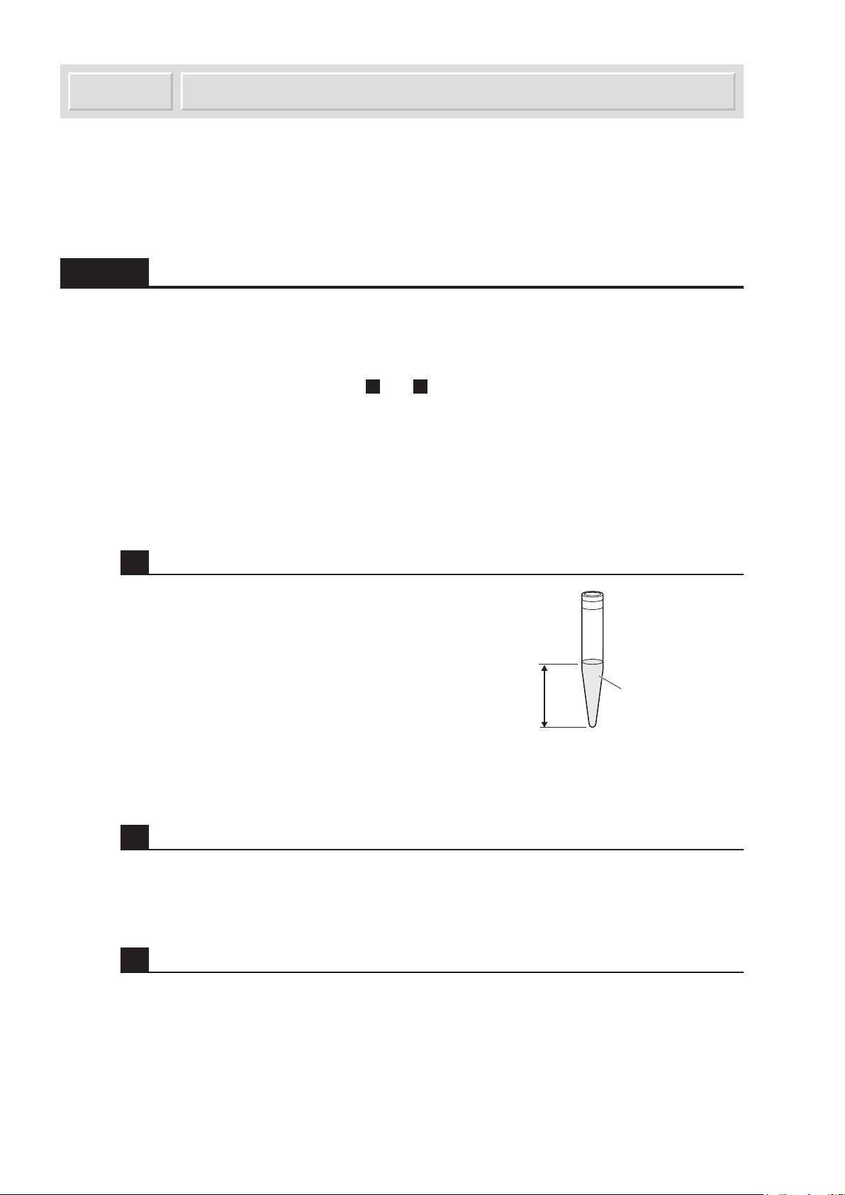
AUTION MAX AX-4030 OPERATING MANUAL
Min. 2 mL
purified water
Low solution
Min.
40 mm
S.G. Calibration2.5
Perform S.G. calibration of the instrument once a month using low and high S.G. standard solutions
and a urinometer. Please ensure the urinometer conforms to the Brix – S.G. conversion formula
described in “1.1.4 Measurement Principle” on page 1-7.
2.5.1 Preparing S.G. Standard Solutions
Prepare: Saccharose, purified water, urinometer, two sample tubes,
sample rack (item rack, STAT and control rack, start rack, or normal rack)
IMPORTANT: Use S.G. standard solutions that meet the following requirements unless
preparing the solutions in steps 1 and 2 .
• Specific gravity readings are between 1.000 to 1.050.
• Difference between the S.G. readings of the high and low solutions is 0.03 or higher.
IMPORTANT: Prepare the S.G. standard solutions just before carrying out calibration. Use
of solutions stored for a long period of time may produce incorrect calibration results.
1 Prepare a low solution.
Use purified water as a low solution.
1 Transfer at least 2 mL of purified water into a
sample tube. Ensure the water level is at least 40
mm above the bottom of the tube.
IMPORTANT: An insufficient amount of low
solution may cause incorrect calibration
results.
2 Prepare a high solution.
2-34
1 Add purified water to 9.3 g of saccharose to make 100 mL of high solution.
3 Take specific gravity readings.
1 Use the urinometer* to accurately measure the S.G. values of the low and high solutions, and
record the values.
* The urinometer should conform to the Brix – S.G. conversion formula described in “1.1.4 Measurement Principle”
on page 1-7. When the high solution prepared in step 2 is measured using the urinometer, the S. G. value should be
1.040.
AX-4030
F
Page 92
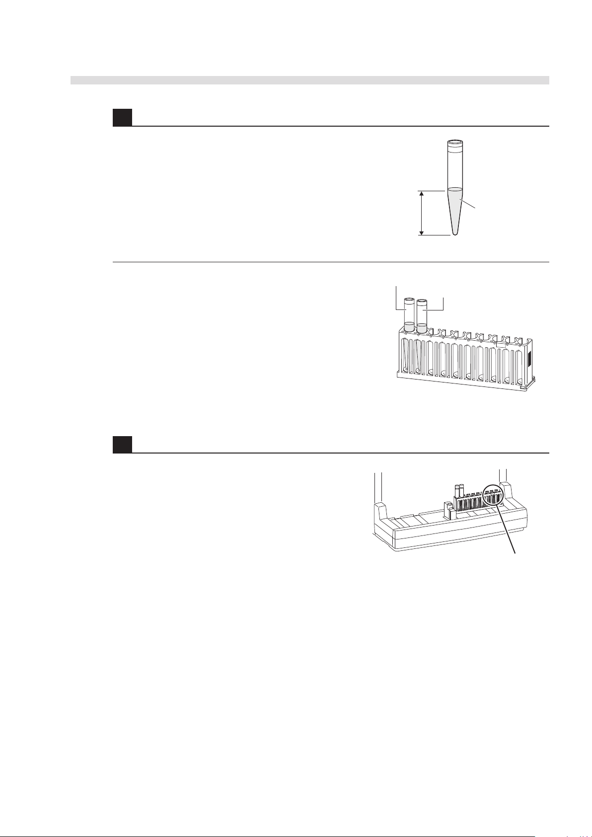
AUTION MAX AX-4030 OPERATING MANUAL
Min. 2 mL water
High solution
Min. 40 mm
Port 1: low solution
Port 2: high solution
Marker
4 Load the S.G. solutions into the sample rack.
1 Transfer at least 2 mL of high solution into a sample
tube. Ensure the liquid level is at least 40 mm above
the bottom of the tube.
IMPORTANT: An insufficient amount of high
solution may cause incorrect calibration
results.
2 Place the low solution tube into port 1 of the sample
rack, and the high solution tube into port 2.
IMPORTANT: Load the two solutions into the
correct ports respectively. Loading them into
the wrong ports may cause an error.
5 Load the sample rack into the sampler.
1 Hold the sample rack with the marker facing you
and place it on the loading side of the sampler.
• First, place the rack at the frontward of the loading
side, fit the recesses at the lower right of the rack
into the guides inside the sampler, and slide the rack
backward.
NOTE: If solution spills on the sampler, immediately
wipe it off. Crystallized solutions may hinder
smooth transportation of the sample racks, and
consequently cause trouble.
D
AX-4030
2-35
Page 93
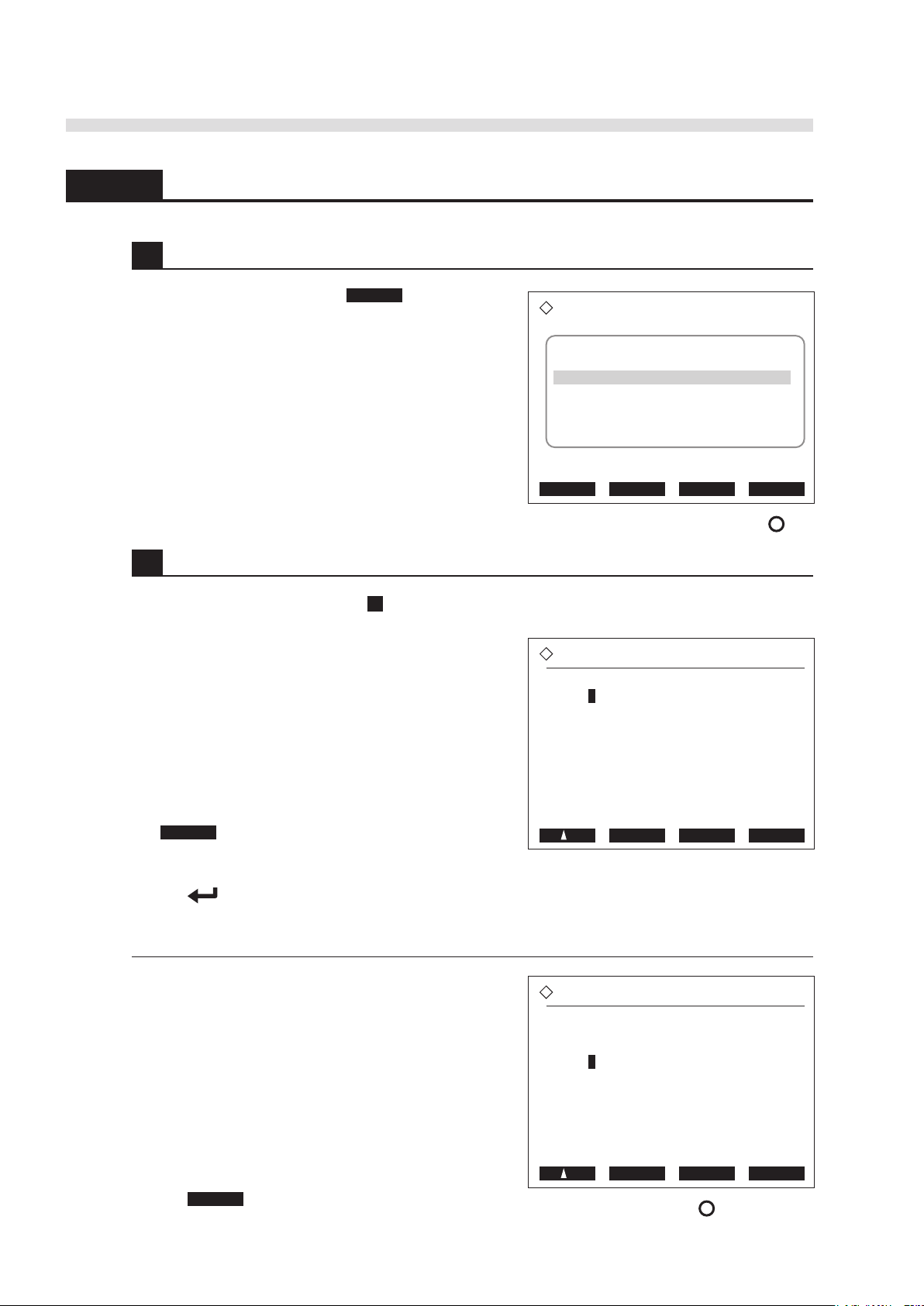
AUTION MAX AX-4030 OPERATING MANUAL
Ready for measurement
2006-01-09 10:30
Measurement start No.
0001
Test strips in feeder 1
1: 9EB
Test strips in feeder 2
2: 9EB
Menu Meas No. Strip S.G. Cal
S.G. Calibration
Standard solution (Low)
<1.000>
Standard solution (High)
<1.040>
BS OK Cancel
S.G. Calibration
Standard solution (Low)
<1.002>
Standard solution (High)
<1.040>
BS OK Cancel
2.5.2 Starting S.G. Calibration
1 Access the S.G. calibration parameters.
1 On the standby screen, press S.G. Cal to go to the
[S.G. calibration] screen.
2 Set the obtained standard S.G. values.
Prepare the notes you took in step 3 in “2.5.1 Preparing S.G. Standard Solutions” on page 2-34.
1 Below [Standard solution (Low)], enter the S.G.
value of the low solution.
• Use the numeric keys (0 to 9).
• The S.G. value acceptable here is between 1.000 to
1.050.
REFERENCE: For example, to enter “1.030”,
press 1, 0, 3, 0 in that order. A decimal point is
automatically added. To correct the entry, press
BS to delete the digits one by one, and enter
a new value.
2 Press to proceed to the [Standard solution
(High)] entry field.
3 Below [Standard solution (High)], enter the S.G.
value of the high solution.
• Use the numeric keys (0 to 9).
• The S.G. value acceptable here is between 1.000 to
2-36
1.050.
4 Press OK to save your entries.
• The next [S.G. Calibration] screen will appear.
AX-4030
B
Page 94
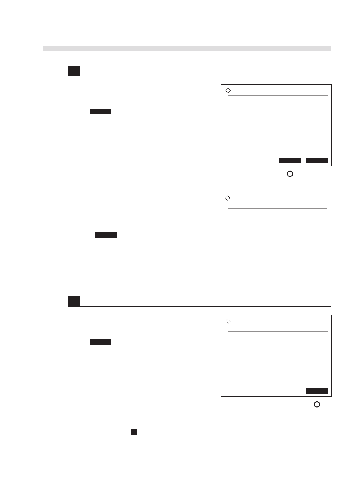
3 Start the S.G. calibration.
S.G. calibration
Prepare S.G. standard solutions.
Start Go back
S.G. calibration
2006-01-09 10:35
Measuring...
Please wait...
S.G. calibration
2006-01-09 10:37
Measurement completed.
Please wait...
Go back
1 Make sure the sample rack with the S.G. standard
solutions are correctly loaded into the sampler.
2 Press Start to start calibration.
AUTION MAX AX-4030 OPERATING MANUAL
• Measurement of the standard solutions will take
place when the sample rack reaches the aspirating
position.
REFERENCE: To stop calibration in progress,
press Stop . The instrument will wait until the
solution measurement in progress completes and
then proceeds to the breaking process before
putting itself back on standby. Note that breaking
calibration aborts all of the calibration results.
4 When S.G. calibration is completed…
• The message “Measurement completed” will
appear.
1 Press Go back to return to the standby screen.
2 Remove the sample rack of the standard solutions
from the sampler.
AX-4030
REFERENCE: If the error “E120” occurs
See “E120” in “5.2.2 Causes and Remedies” on page 5-8 to determine the cause of the error,
and retry from step 1 . If the error persists, there is something wrong with the instrument.
Contact your distributor.
2-37
Page 95
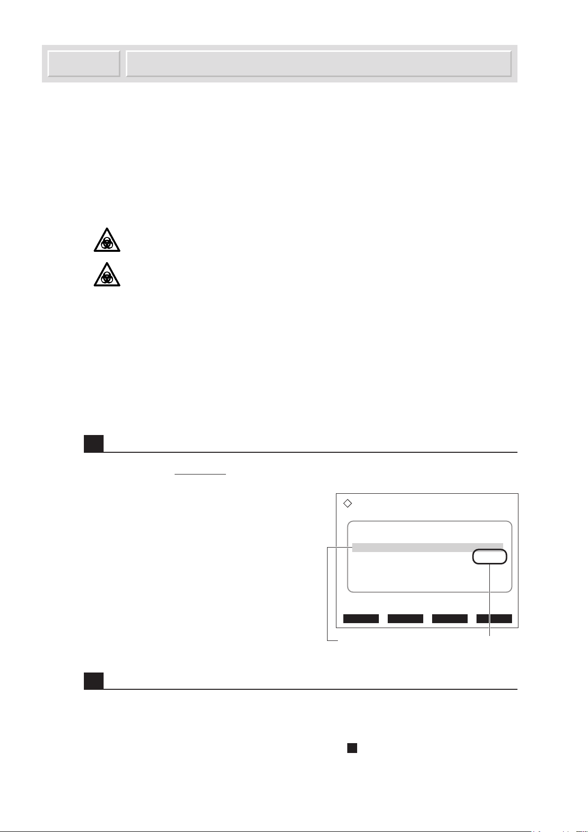
AUTION MAX AX-4030 OPERATING MANUAL
Ready for measurement
2006-01-09 13:00
Measurement start No.
0001
Test strips in feeder 1
1: 9EB
Test strips in feeder 2
2: 9EB
Menu Meas No. Strip S.G. Cal
Type of test strips
Main feeder (light blue background)
Control Measurement2.6
Perform control measurement at regular intervals so as to maintain the status of the instrument and
measurement quality. Up to 3 types or concentrations of controls can be measured by loading them
into the STAT and control rack (control measurement can be performed using at least one control,
and does not always require three different controls). Up to 200 control measurement results can be
stored in memory.
Prepare: Commercially available controls, STAT and control rack, sample tubes,
and protective gloves
Wear protective gloves to prevent exposure to pathogenic microbes.
Discard used controls, test strips, and protective gloves in accordance
with local regulations for biohazardous waste.
REFERENCE: This section describes how to perform control measurement when on standby.
However, controls can also be measured before or in course of normal measurement by
inserting the STAT and control rack at the beginning of or between the racks containing patient
samples.
REFERENCE: For the controls labeled with barcodes, “control IDs” read from the barcodes are
automatically assigned to the corresponding control measurement results.
1 Check the main feeder.
The test strips in the main feeder are always used for control measurement.
1 On the standby screen, check if the main feeder
and the test strips for the feeder are set as you
desire.
• The main feeder is indicated by a light blue
background.
2 Load the test strips into the main feeder.
1 Place the test strips in the main feeder.
• Any types of test strips can be used as long as they are supported by the instrument.
• For detailed instructions, see “2.3.3 Loading Test Strips into the Feeders” on page 2-16. The
main feeder and test strips settings can be changed in step 1 in that section.
2-38
AX-4030
C
Page 96
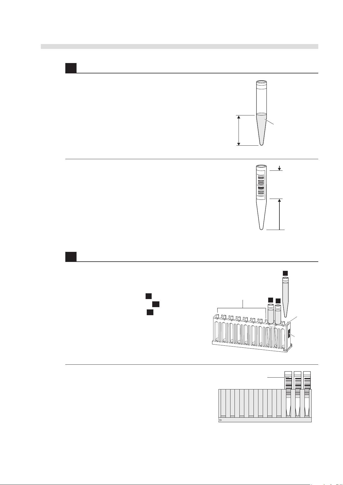
3 Prepare controls.
Min. 2 mL of control
Min. 40 mm
Min. 30 mm
Min. 5 mm
Black label
Dark blue
adapters
STAT and control rack
Keep empty.
H
L
M
Barcode label
Rear of STAT and control rack
IMPORTANT: Read through the package inserts
before using the controls.
1 Transfer at least 2 mL of control into a sample tube.
Ensure the liquid level is at least 40 mm above the
bottom of the tube.
IMPORTANT: An insufficient amount of controls
may produce incorrect results.
REFERENCE: To have the built-in barcode reader
read barcodes successfully, label the tubes as
shown in the figure.
AUTION MAX AX-4030 OPERATING MANUAL
4 Load the controls into the STAT and control rack
1 Insert the sample tubes into ports 8, 9, and 10 (with
dark blue adapters) in that order.
Port 8: Low density control
Port 9: Middle density control
Port 10: High density control H
REFERENCE: Do not place the controls in ports
1 to 7 with the orange adapters, as they are
dedicated to rack STAT measurement.
REFERENCE: To have the built-in barcode reader
read barcodes successfully, labels on the tubes
must be facing to the rear side of the sample rack.
L
M
D
AX-4030
2-39
Page 97
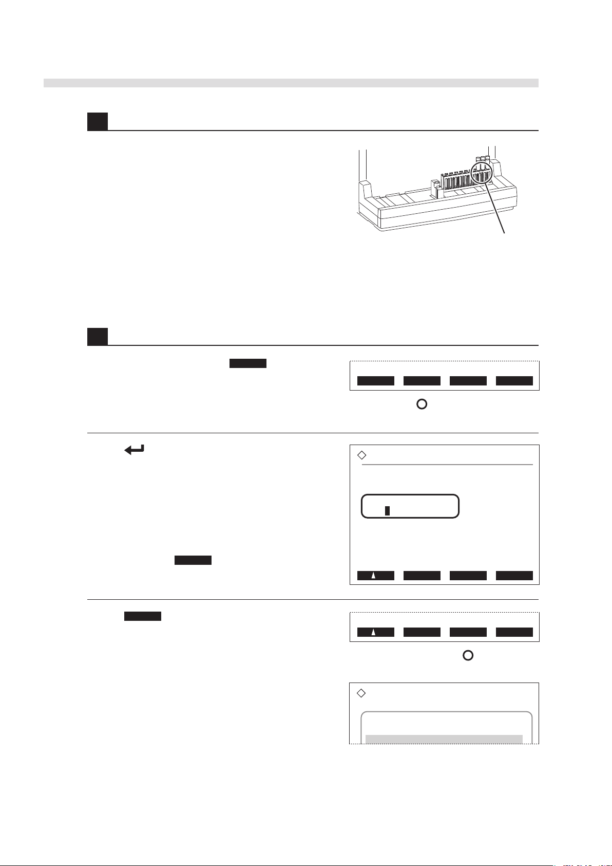
AUTION MAX AX-4030 OPERATING MANUAL
Marker
Menu Meas No. Strip S.G. Cal
Measurement start No.
Normal measurement
<0001>
Control measurement
<0001>
BS OK Cancel
BS OK Cancel
Ready for measurement
2006-01-09 13:15
Measurement start No.
0150
Test strips in feeder 1
5 Load the STAT and control rack into the sampler.
1 Hold the sample rack with the marker facing you
and place it on the loading side of the sampler.
• First, place the rack at the frontward of the loading
side, fit the recesses at the lower right of the rack
into the guides inside the sampler, and slide the rack
backward.
NOTE: If a control spills on the sampler, immediately wipe it off. A crystallized control may hinder
smooth transportation of the sample racks, and consequently cause trouble.
6 Set the measurement start number.
1 On the standby screen, press Meas No. to go to the
[Measurement start No.] screen.
2 Press to move down to [Control measurement].
3 Enter a number between 0000 to 9999 to be
assigned to the first control.
• Use the numeric keys (0 to 9).
REFERENCE: For example, to enter “0150”,
press 0, 1, 5, and 0 in that order. To correct the
number, press BS to delete digits one by
one, and enter a new number.
4 Press OK to save your changes.
• The standby screen will appear again with a new
measurement start number.
2-40
AX-4030
D
Page 98
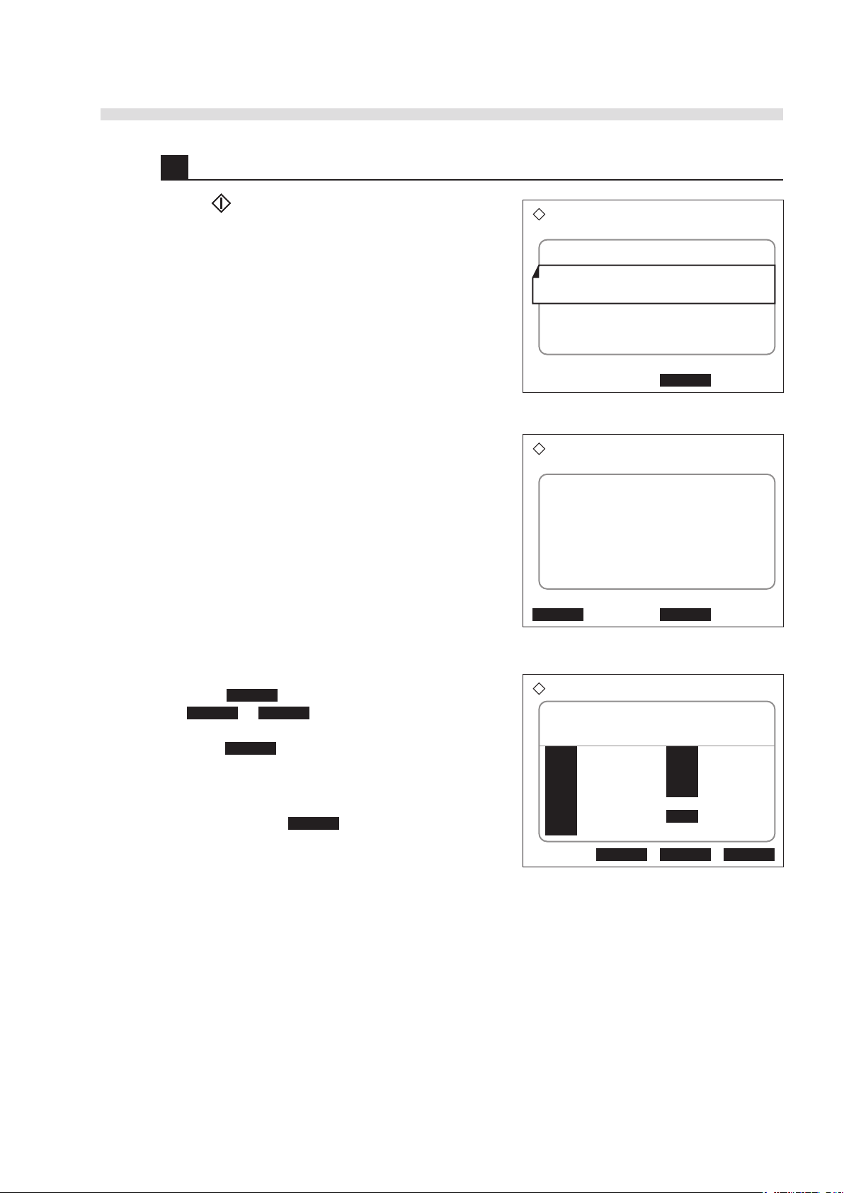
7 Measure the controls.
Ready for measurement
2006-01-09 13:15
Port No.
0001
Measurement No.
0150
ID
----------------- Test strip type
1: 9EB
Stop
Waiting for rack...
Ready for measurement
2006-01-09 13:17
Port No.
0001
Measurement No.
0150
ID
----------------- Test strip type
1: 9EB
Results Stop
View
Date 2006-01-09 13:17 Kind CONTROL
No. 0001 Po. 001-05 Strip 1: 9EB
ID 000000000000000000
GLU - *PRO 4+
BIL - URO NORMAL
PH 7.0 !BLD + *KET 4+ NIT LEU -
TURB - S.G. 1.000
COLOR LIGHT YELLOW
<<<<<<<< >>>>>>>> Go back
1 Press to start.
• The STAT and control rack will be transported to
the aspirating position while “Waiting for rack…” is
displayed.
• The nozzle will come down to aspirate the first
control, and then the measurement operation takes
place.
AUTION MAX AX-4030 OPERATING MANUAL
• When the result is obtained, it will be printed. See
“2.8.2 Printed Results Report” on page 2-50.
• The following controls are processed in the same
way.
REFERENCE: To view results
Press Results to view the latest result. Pressing
<<<<<<<< or >>>>>>>> can display the previous or
next result. To return to the [Measuring…] screen,
press Go back .
REFERENCE: To stop control measurement in
progress, press Stop . The instrument will
perform the breaking process and put itself on
standby.
B
AX-4030
2-41
Page 99

AUTION MAX AX-4030 OPERATING MANUAL
8 When control measurement is completed…
• The STAT and control rack will be discharged to the unloading side of the sampler.
REFERENCE: In the case that control measurement was carried out at the beginning or in
course of normal measurement, normal measurement will start or resume at this point.
1 Remove the STAT and control rack from the sampler.
2-42
AX-4030
Page 100
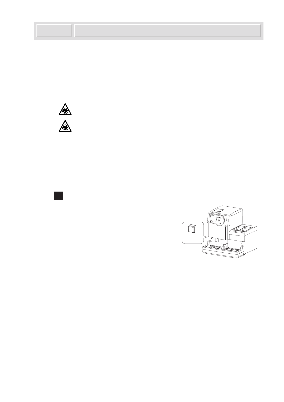
AUTION MAX AX-4030 OPERATING MANUAL
Standby
switch
Check Measurement2.7
If you suspect obtained results are inadequate, use the supplied check strips to examine the status of
the instrument. The check strip container holds two gray strips and two white strips. Use a pair of
white and gray strips for check measurement at a time.
Prepare: Gray and white check strips (one for each color), blower brush, alcohol, cloth,
tissue paper, and protective gloves.
Wear protective gloves to prevent exposure to pathogenic microbes.
Discard cleaning tools and used protective gloves in accordance with local
regulations for biohazardous waste.
IMPORTANT: Do not touch the pad area on the check strips. Use of strips contaminated
by sebum can produce incorrect results.
NOTE: Ensure you have the check strips that came with the instrument. Measuring other test
strips in the check measurement mode can cause trouble or damage to the instrument.
1 Clean the test strip transportation path.
1 If the instrument is powered on, make sure the
standby screen is displayed. Then, press the standby
switch to turn off the power.
2 Clean the components listed below.
Feeders: See page 4-6.
Introduction tray: See page 4-12.
Transport tray: See page 4-19.
Waste box: See page 4-3.
NOTE: Without cleaning these parts before check measurement, the check strips may be
contaminated and become unusable.
NOTE: After taking the test strips out of the feeders for cleaning, wrap the strips with tissue
paper to protect from dust.
D
AX-4030
2-43
 Loading...