

Ariston TH 721 D22 B/NG, TH 731 D2/A B/NG, TH 721 D22 B/TG, TH 731 D2/A B/LPG, TH 731 D2/A B/TG User Manual
...Page 1

1
TH 721 D22 B/LPG
TH 721 D22 B/NG
TH 721 D22 B/TG
TH 731 D2/A B/LPG
TH 731 D2/A B/NG
TH 731 D2/A B/TG
TH 931 D2/A B/LPG
TH 931 D2/A B/NG
TH 931 D2/A B/TG
TH 721 D22 E/LPG
TH 721 D22 E/NG
TH 721 D22 E/TG
TH 731 D2/A E/LPG
TH 731 D2/A E/NG
TH 731 D2/A E/TG
TH 931 D2/A E/LPG
TH 931 D2/A E/NG
TH 931 D2/A E/TG
Page 2

1
Table of Contents
For your safety
Pg2
Warnings
Pg2
The appliance
Pg3
Description of the appliance
Pg3-5
Installation
Pg6-12
Start-up and Use
Pg13-14
Precautions and tips
Pg14
General safety
Pg14
Assistant
Pg15
Cleaning and maintenance
Pg15
Practical tips
Pg16
FAQs and Trouble shooting
Pg17
Electrical connection
Pg18
Page 3

2
For your safety
These instructions have been drawn up for your safety and that of others. You are therefore
requested to read them carefully before installing and using the appliance. Keep this
instruction manual for future reference as necessary. If the appliance is sold or moved, make
sure that the manual is handed over to the new user.
WARNINGS
WARNING: The appliance and its accessible parts become hot during use. Care should be
taken to avoid touching heating elements. Children less than 8 years of age shall be kept away
unless continuously supervised. This appliance can be used by children aged from 8 years
and above and persons with reduced physical, sensory or mental capabilities or lack of
experience and knowledge if they have been given supervision or instruction concerning use
of the appliance in a safe way and understand the hazards involved. Children shall not play
with the appliance. Cleaning and user maintenance shall not be made by children without
supervision.
WARNING: Unattended cooking on a cooktop with fat or oil can be dangerous and may result
in fire. NEVER try to extinguish a fire with water, but switch off the appliance and then cover
flame e.g. with a lid or a fire blanket.
WARNING: Danger of fire: do not store items on the cooking surfaces.
Never use steam cleaners or pressure cleaners on the appliance.
Remove any liquid from the lid before opening it. Do not close the glass cover (if present)
when the gas burners or electric hotplates are still hot.
The appliance is not intended to be operated by means of an external timer or separate remote
control system.
CAUTION: the use of inappropriate cooktop guards can cause accidents.
Page 4
3
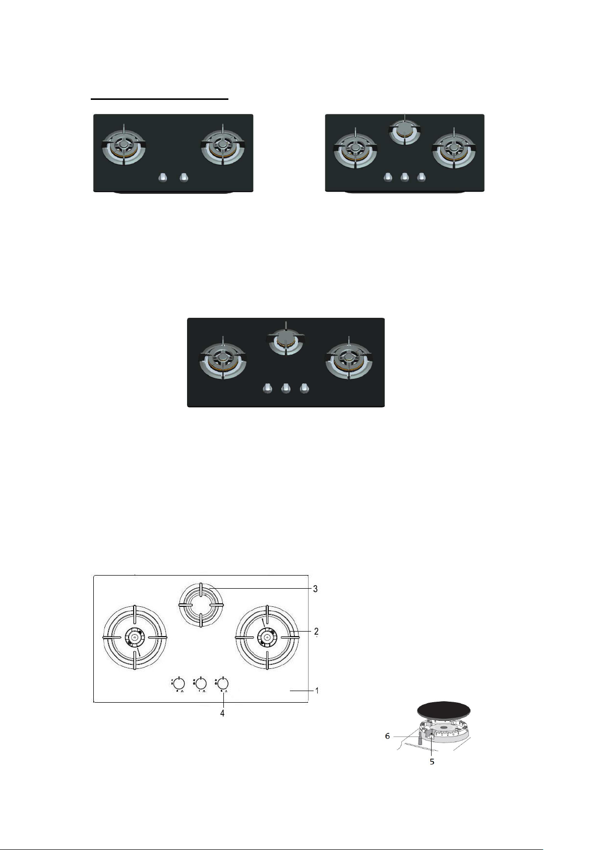
THE APPLIANCE
1. Hob
2. Double ring wok burner
3. Auxiliary burner (on certain models)
4. Burner control knobs
5. Ignition for gas burner
6. Safety devices (on certain models)
TH 721 D22 B/LPG TH 731 D2/A B/LPG
TH 721 D22 B/NG
TH 721 D22 B/TG
TH 721 D22 E/LPG
TH 721 D22 E/NG
TH 721 D22 E/TG
TH 731 D2/A B/NG
TH 731 D2/A B/TG
TH 731 D2/A E/LPG
TH 731 D2/A E/NG
TH 731 D2/A E/TG
TH 931 D2/A B/LPG TH 931 D2/A E/LPG
TH 931 D2/A B/NG TH 931 D2/A E/NG
TH 931 D2/A B/TG TH 931 D2/A E/TG
DESCRIPTION OF THE APPLIANCE
Page 5

4
The Gas cooktop, which can be used built-in, are supplied with two or three burners with glass
Model number
Burner Variants
Wok
burner
Semi-rapid
burner
Total
Dimensions
TH 721 D22 B/LPG
209kW(655g/h)
(760 X 450)mm
TH 731 D2/A B/LPG
2
1
11kW(800g/h)
(760 X 450)mm
TH 931 D2/A B/LPG
2
1
11kW(800g/h)
(860 X 500)mm
TH 721 D22 E/LPG
209kW(655g/h)
(760 X 450)mm
TH 731 D2/A E/LPG
2
1
11kW(800g/h)
(760 X 450)mm
TH 931 D2/A E/LPG
2
1
11kW(800g/h)
(860 X 500)mm
Note:
Wok burner = Rated at 4.5kW
Auxiliary burner = Rated at 2.0kW
Model number
Burner Variants
Wok
burner
Semi-rapid
burner
Total
Dimensions
TH 721 D22 B/TG
209kW
(760 X 450)mm
TH 731 D2/A B/TG
2111.3kW
(760 X 450)mm
TH 931 D2/A B/TG
2111.3kW
(860 X 500)mm
TH 721 D22 E/TG
209kW
(760 X 450)mm
TH 731 D2/A E/TG
2111.3kW
(760 X 450)mm
TH 931 D2/A E/TG
2111.3kW
(860 X 500)mm
Note:
Wok burner = Rated at 4.5kW
Auxiliary burner = Rated at 2.3kW
panel.Please refer to the table below for the detail of wok burner. All of the burners are
manufactured by HORISUN. Each burner, which is operated by a FSD/plug type gas valve, is
controlled by metal control knobs positioned on the front of the panel, Each burner
incorporates a flame.
supervision device(Thermo couple).The appliance incorporated a battery supply of 1.5V or
electric supply of 220-240V that operates the ignition system.
The detailed differences between the models are listed below:
Page 6

5
Model number
Burner Variants
Wok
burner
Semi-rapid
burner
Total
Dimensions
TH 721 D22 B/NG
209kW
(760 X 450)mm
TH 731 D2/A B/NG
2110.7kW
(760 X 450)mm
TH 931 D2/A B/NG
2110.7kW
(860 X 500)mm
TH 721 D22 E/NG
209kW
(760 X 450)mm
TH 731 D2/A E/NG
2110.7kW
(760 X 450)mm
TH 931 D2/A E/NG
2110.7kW
(860 X 500)mm
Note:
Wok burner = Rated at 4.5kW
Auxiliary burner = Rated at 1.7kW
Burner
Injector
size(mm)
Injector
marking
Full rate
kW
For LPG
Wok
Inner ring
0.4
40
4.5
Outer ring
0.95
95
Auxiliary
0.65652
For TG(G110)
Wok
Inner ring
1.3
130
4.5
Outer ring
Auxiliary
2.2
220
2.3
For NG
Wok
Inner ring
0.6
60
4.5
Outer ring
1.4
140
Auxiliary
0.95
95
1.7
2.9 290
Page 7

6
Installation Instructions for Built-In
The following instructions are intended for the installer so that the installation and maintenance
procedures may be followed in the most professional and expert manner possible.
Positioning
This appliance may only be installed and operated in permanently ventilated rooms in
compliance with provisions laid down by current regulations and standards. The following
requirement must be observed:
A)The room must be fitted with a ventilation system which vents smoke and gases from
combustion to outside. This is must be done by means of a hood or electric ventilator that turns
on automatically each time the hood is operated.
In a chimney stack or branched flue. Directly to the Outside
(exclusively for cooking appliances)
Page 8

7
B)The room must also allow for the influx of the air needed for proper combustion. The flow of
C)Intensive and prolonged use of the appliance may necessitate supplemental ventilation,
air for combustion purposes must not be less than 2 m3/h per kW of installed capacity. The
supply of said air can be effected by means of direct influx from the outside through a duct with
a inner cross section of at least 100 cm2 which must not be able to be accidentally blocked.
Those appliances which are not fitted with a safety device to prevent the flame from
accidentally going out must have a ventilation opening twice the size otherwise required, i.e. a
minimum of 200 cm2 (Fig. A). Otherwise, the room can be vented indirectly though adjacent
rooms fitted with ventilation ducts to the outside as described above, as long as the adjacent
rooms are not shared areas, bedrooms or present the risk of fire (Fig. B).
e.g. opening a window or increasing the power of the air intake system (if present)
D) Liquefied petroleum gases are heavier than air and as a result, settle downwards. Rooms in
which LPG tanks are installed must be fitted with ventilation openings to the outside in order to
allow the gas to escape in the event of a leak. Therefore, LPG tanks, whether empty or
partially full, must not be installed or stored in rooms or spaces below ground level (cellars,
etc.). It is also a good idea to keep only the tank currently being used in the room, making sure
that it is not near sources of heat (ovens, fireplaces, stoves, etc.) that could raise the internal
temperature of the tank above 500C.
Page 9

8
Installation of Built-In cooktops
The appliance can be installed next to furniture units which are no taller than the top of the
cooker. The wall in direct contact with the back panel of the cooker must be made of
non-flammable material. During operation the back panel of the cooker could reach a
temperature of 500C above room temperature. For proper installation of the cooker, the
following precautions must be taken:
• Kitchen cabinets adjacent to the appliance and taller than the top of the cooktop must be at
least 200 mm from the edge of the cooktop.
• Hoods must be installed according to their relative installation instruction manuals and at a
minimum distance of 650 mm from the cooktop.
• Place the wall cabinets adjacent to the hood at a minimum height of 420 mm from the
cooktop (see figure C).
If the cooktop is installed beneath a wall cabinet, the latter must be situated at a minimum of
720mm above the cooktop.
.
Page 10

9
The dimensions of the cutout for the appliance must be those indicated in the figure D. Clamps
are provided to fasten the cooktop to counters measuring from 20 to 60 mm in thickness. To
fasten the cooktop securely, it is recommended that all the clamps be used.
TH 721 D22 B/LPG TH 931 D2/A B/LPG
TH 721 D22 B/LPG TH 931 D2/A B/LPG
TH 721 D22 B/TG TH 931 D2/A B/NG
TH 731 D2/A B/LPG TH 931 D2/A B/TG
TH 731 D2/A B/NG TH 931 D2/A E/LPG
TH 731 D2/A B/TG TH 931 D2/A E/NG
TH 731 D2/A E/LPG TH 931 D2/A E/TG
TH 731 D2/A E/NG
TH 731 D2/A E/TG
There should be at least 170mm between top and the cabinet.
FIG.D.
Front
Page 11

10
The cooktop can also be installed above built-in ovens provided with cooling
ventilation.
In the event the cooktop is installed above a built-in oven, a wood panel must be inserted as
insulation. This panel must be placed at about 50 mm from the bottom of the cooktop itself.
Important: When installing the cooktop above a built-in oven, the oven should be placed on
two wooden strips; in the case of a joining cabinet surface, remember to leave a space of at
least 45 x 560 mm at the back.
Installation of Built-In Cooktops on a CYLINDER COMPARTMENT
In the event the cooktop is installed above cylinder compartment, a wood panel must be
inserted as insulation. This panel must be placed at about 50 mm from the bottom of the
cooktop itself.
The opening of this compartment have to permit the easy introduction and removal of the
cylinder. The dimension of the opening and the inside of the compartment shall be at least
large enough to accommodate the cylinders (with regulator fitted) which are the most
commonly used in the country. The total area of the opening in the upper part shall be at least
1/100 of the floor area of the compartment. The total area of the openings of the base shall be
at least 1/50 of the floor area of the compartment. The cylinder support:
Shall have sufficient mechanical strength.
Shall not let the cylinder rest directly in the ground.
Shall not sill higher than the base on which the cylinder rests.
The cylinder tap have to be readily accessible.
Overflow of liquid from pans of the hotplate shall not fall onto cylinder or its accessories.
The flexible tube shall not be in contact with sharp edges. No internal communication shall
exist between the cylinder compartment and the different parts of the appliance where burners
are placed.
The ventilation openings of the compartment cannot be obstructed when the appliance is
placed in position.
Page 12

11
Gas Connection for Cooktop
The cooktop should be connected to the gas supply by an authorized installer. During
installation of this product it is essential to fit an approved gas tap to isolate the supply from the
appliance for the convenience of any subsequent removal or servicing. Connection of the
appliance to the gas mains or liquid gas tanks must be carried out according to the safety
standards currently in force, and only after it is ascertained that it is suitable for the type of gas
to be used. If not, follow the instructions indicated in the section entitled, “Adapting the cooktop
for Different Types of Gas”. If the cooktop is to be connected to tanks containing liquid gas, use
pressure regulators that comply with current safety standards.
Important: To insure that the appliance operates safety, the gas is regulated correctly and
your appliance lasts overtime, make sure that gas pressure levels comply with the indications
given , “Nozzle and Burner Specifications”.
Gas connection to Non-flexible Pipe
(Copper or Steel)
Connection to the gas source must be done in such a way as to not create any stress points at
any part of the appliance.
The appliance is fitted with an adjustable, “L” shaped connector and a gasket for the
attachment to the gas supply. Should this connector have to be turned.
The gasket must be replaced (supplied with the appliance).
The gas feed connector to the appliance is a threaded, male 1/2” connector for round gas pipe.
Gas Connection to Flexible Steel Pipe
The gas feed connector to the appliance is a threaded, male 1/2” connector for round gas pipe.
Only use pipes, tubes and gaskets that comply with current safety codes. The maximum length
of the flexible pipes must not exceed 2000 mm. Once the connection have been made, ensure
that the flexible metal tube does not touch any moving parts and not crushed.
Page 13

12
Check the Seal
Once the appliance have been installed, make sure all the connections are properly sealed,
using a soapy water solution. Never use a flame.
How to load battery ( on those models fitted with battery box)
Open the battery box, and then place a 1.5V size “D” battery into the box.( take notice of the
direction)
Note:
a) "prior to installation, ensure that the local distribution conditions (nature of the gas and
gas pressure) and the adjustment of the appliance are compatible";
b) "the adjustment conditions for this appliance are stated on the label (or data plate)";
c) "this appliance is not connected to a combustion products evacuation device. It shall be
installed and connected in accordance with current installation regulations. Particular
attention shall be given to the relevant requirements regarding ventilation".
CAUTION: “In case of cooktop glass breakage: shut immediately off all burners and any
electrical heating element and isolate the appliance from the gas supply do not touch the
appliance surface, do not use the appliance.”
The appliance shall not be operated for more than 15 s. If after 15 s the burner has not lit,
stop operating the device and open the compartment door and/or wait at least 1 min before
attempting a further ignition of the burner.
In the event of the burner flames being accidentally extinguished, turn off the burner control and
do not attempt to re-ignite the burner for at least 1 min.
Burner cap placement instruction.
Please see below picture to set the burner cap groove to the arrow,make sure the burner cap
is placed well before cooking.
Page 14

13
START UP AND USE
The position of the corresponding gas burner is indicated on each control knob.
Gas Burners
The burners differ in size and power. Choose the most appropriate one for the diameter of the
cookware being used.
The burner can be regulated with the corresponding control knob by using one of the following
settings:
Symbol description
To turn on one of the burner, please press the corresponding knob all the way in and turn in
the counter-clockwise direction to the “high” setting.( On those models fitted with safety
devices, user must keep the knob press down until the burner ignites for approximately 3
seconds to allow the safety device to heat up.)
Caution: If the burner accidentally goes out, turn off the gas with the control knob and
try to light it again after waiting at least 1 minute.
To Turn off a burner, turn the knob in the clockwise direction until it stops (it should be on the
“●” setting).
Use the appropriate cookware, whose diameter is shorter than the hot plates’ for each burner
in order to save energy.
Page 15

14
PRECAUTIONS AND TIPS
This Manual is for a class 3 built-in or or class 2 built with oven beneath.
Gas appliances require regular air exchange to maintain efficient operation. When
These instructions are only valid for the countries the symbols for which appear on the
Always use original Spare Parts.
This appliance is designed for non-professional use in the home and its features and
Do not touch the appliance with bare feet or with wet or damp hands and feet.
Avoid improper and/or dangerous use.
Avoid obstructing the ventilation or heat dissipation slots; The openings used for
Ensure that the power supply cables of other electrical appliances do not come into
Avoid using flammable liquids nearby.
Avoid using adaptors, multiple outlet plugs and/or extensions.
The appliance must not be installed outdoors, even in covered areas. It is extremely
Avoid Using unstable or deformed cookware.
Never trying to install or repair the appliance without the assistance of qualified
Prevent children and the disabled from coming into contact or having access to
General safety
This appliance has been designed and manufactured in compliance with international safety
standards. The following warnings are provided for safety reasons and must be read carefully.
Call only the Service Centers authorized by the manufacturer, its service agent or
similarly qualified persons in order to avoid a hazard.
installing the cooktop, follow the instructions provided
manual and the serial plate.
technical characteristics must not be modified.
ventilation and dispersion of heat must never be covered.
contact with the hot parts of the cooktop
dangerous to leave the appliance exposed to rain and storms.
personnel.
the following, as they are possible sources of danger:
- The controls and the appliance in general.
- The packaging (plastic bags, polystyrene, nails, etc.).
- The appliance, during the immediately after use given the heat generated by its use.
- The appliance when no longer in installed (in this case, all potentially dangerous parts
must be made safe).
Page 16

15
It is recommended that you follow the guidelines below:
Only use the appliance to cook food, avoiding all other uses.
Check the condition of the appliance after it has been unpacked.
When not in use, take out the battery and turn off the gas valve (if present).
Always check to make sure that the control knobs are on the “●” setting when the
appliance is not in use;
The manufacturer will not held liable for any damages arising out of : incorrect
installation or improper, incorrect or unreasonable use.
Assistant
The assistance of qualified personnel must be called upon in the following cases:
Installation (in accordance with the manufacturer’s instructions)
When in doubt about the operation of the appliance;
Contact service centers authorized by the manufacturer in the following cases:
When in doubt about the condition of the appliance after having removed the packing;
In the case of the breakdown or malfunction: ask for original spare parts.
CLEANING and MAINTENANCE
Before cleaning or performing maintenance, disconnect the appliance from the gas supply and
allow it to cool down
General cleaning
To extend the life of the cooktop, it is absolutely indispensable that it be cleaned carefully and
thoroughly on a frequent basis, keeping in mind the following:
1. Do not use steam equipment to clean the appliance.
2. The enameled parts and the glass top, if present, must be washed with warm water without
using abrasive powders or corrosive substances which could ruin them.
3. The removable parts of the burners should be washed frequently with warm water and soap,
making sure to remove caked-on substances.
4. On cooktops with automatic ignition, the end of the electronic ignition device must be
cleaned carefully and frequently, making sure that the gas holes are not clogged.
5. Stainless steel can be stained if it remains in contact with highly calcareous water or
aggressive detergents (containing phosphorous) for an extended period of time. It is
recommended that these parts be rinsed thoroughly with water and then dried well. It is also a
good idea to clean up any spills.
Page 17

16
Greasing the Taps
The taps may jam in time or they may become difficult to turn. If so, the tap itself must be
replaced.
N.B.: This operation must be performed by a technician authorized by the manufacturer.
PRACTICAL TIPS
Using the Burners
For best performance, follow these general guidelines:
1. Use the appropriate cookware for each burner (see table) in order to prevent the flame from
reaching the sides of the pot or pan;
2. Always use cookware with a flat bottom and keep the lid on;
3. When the contents come to a boil, turn the knob to “Low”
Page 18

17
FAQ and TROBULE SHOOTING
FAQs
Possible Reasons
Solutions
The burner does
not light or the
flame is not
uniform around
and burner.
Burner
The gas holes on the
burner are clogged.
The gas holes on the
burner are not clogged.
Some movable parts
that make up the
burner are mounted
wrongly.
All of the movable parts
that make up the burner
are mounted correctly.
There are draughts
around and cooking
surface.
There are no draughts
around and cooking
surface.
The burner does
not remain on
when set to “Low”.
Burner
The gas holes on the
burner are clogged.
The gas holes on the
burner are not clogged;
There are draughts
near the cooking
surface.
There are no draughts near
the cooking surface.
There minimum not
adjusted correctly.
There minimum has been
adjusted correctly (see the
section entitled, “Minimum
Regulation”).
The cookware is
not stable.
Cookware
The bottom of the
cookware is not flat.
The bottom of the
cookware is perfectly flat.
The cookware is not
centered correctly on
the burner.
The cookware is centered
correctly on the burner.
The support grids have
been inverted.
The support grids have not
been inverted.
It may occur that the cooktop does not function or does not function properly. Before calling
customer service for assistance, check with below.
First of all, check to see that there are no interruptions in the gas and battery supplies, and, in
particular, that the gas valves for the mains are open.
Page 19

18
Electrical connection
19
Page 20

19
Electrical connection models
TH 721 D22 E/LPG
TH 721 D22 E/NG
TH 721 D22 E/TG
TH 931 D2/A E/LPG
TH 931 D2/A E/NG
TH 931 D2/A E/TG
TH 731 D2/A E/LPG
TH 731 D2/A E/NG
TH 731 D2/A E/TG
 Loading...