

La ringraziamo per aver scelto un prodotto Ariston, sicuro e davvero facile da usare. Per conoscerlo, utilizzarlo al
A
B
C
meglio e a lungo, le consigliamo di leggere questo manuale. Grazie
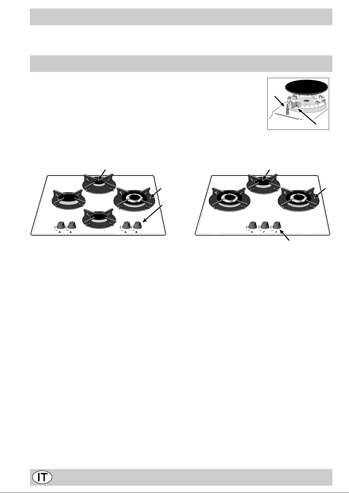
Visto da vicino
A. Bruciatori gas
B. Griglie di appoggio per recipienti di cottura
C. Manopole di comando dei bruciatori gas
D. Candela di accensione dei bruciatori gas (presen-
te solo su alcuni modelli)
F. Dispositivo di sicurezza (presente solo su alcuni mo-
delli) - Interviene in caso di spegnimento accidentale
della fiamma (trabocco di liquidi, correnti d'aria, ...)
bloccando l'erogazione del gas al bruciatore.
A
B
C
F
D
2

Come utilizzarlo
Su ciascuna manopola è indicata la posizione del bruciatore gas corrispondente.
Bruciatori gas
Sono di diverse dimensioni e potenze. Scegliete quello
più adatto al diametro del recipiente da utilizzare.
Il bruciatore prescelto può essere regolato dalla manopola corrispondente come segue:
• Spento
Massimo
Minimo
Per accendere uno dei bruciatori, avvicinare allo stesso una fiamma o un accenditore, premere a fondo e
ruotare la manopola corrispondente in senso antiorario
fino alla posizione di massima potenza.
Come tenerlo in forma
Prima di ogni operazione disconnettere l'apparecchio dall'
alimentazione elettrica.
Per una lunga durata del piano è indispensabile eseguire frequentemente una accurata pulizia generale,
tenendo presente che:
· per la pulizia non utilizzare apparecchi a vapore
• le parti smaltate ed in vetro vanno lavate con acqua
tiepida senza usare polveri abrasive e sostanze corrosive che potrebbero rovinarli;
• gli elementi mobili dei bruciatori vanno lavati frequentemente con acqua calda e detersivo avendo cura di
eliminare le eventuali incrostazioni;
• nei piani dotati di accensione automatica occorre procedere frequentemente ad una accurata pulizia della
parte ter minale dei dispositivi di accensione istantanea elettronica e verificare che i fori di uscita del gas
non siano ostruiti;
• il piano va pulito con prodotti per la pulizia dei vetri.
Evitare l'utilizzo di prodotti e pagliette abrasive che possono provocare rigature sul vetro.
• la superficie del piano dovrà essere pulita regolarmente
con una soluzione di acqua tiepida e detergente non
abrasivo. Dapprima togliere dal piano di cottura tutti i
resti di vivande e spruzzi di grasso con un raschietto
per la pulizia per esempio (non in dotazione) (Fig. A).
Nei modelli dotati di dispositivo di sicurezza "F", è necessario mantenere premuta la manopola per circa 6 secondi finchè non si scalda il dispositivo che mantiene automaticamente accesa la fiamma .
Nei modelli dotati di candela di accensione "D", per
accendere il bruciatore prescelto è sufficiente prima premere a fondo la manopola corrispondente, poi ruotarla in
senso antiorario fino alla posizione di massima potenza,
tenendola premuta fino alla avven uta accensione.
Avvertenza: nel caso di una estinzione accidentale delle
fiamme del bruciatore, chiudere la manopola di comando
e ritentare l’accensione dopo almeno 1 minuto.
Per spegnere il bruciatore occorre ruotare la manopola
in senso orario fino all’arresto (corrispondente al simbolo
“•”).
Pulire il piano di cottura quando è tiepido; utilizzare un
prodotto di pulizia adatto, strofinare con un panno
umido ed asciugare. Zucchero o vivande ad alto contenuto zuccherino vanno eliminati immediatamente
dalla zona di cottura ancora calda con un raschietto.
In nessun caso utilizzare spugne o prodotti abrasivi,
anche detersivi chimicamente aggressivi come gli
spray da f orno o prodotti smacchianti vanno evitati (Fig.
B);
Fig. A Fig. B
Ingrassaggio dei rubinetti
Con il tempo può verificarsi il caso di un rubinetto che si
blocchi o presenti difficoltà nella rotazione, pertanto sarà
necessario provvedere alla sostituzione del rubinetto stesso.
N.B.: Questa operazione de ve essere effettuata da un
tecnico autorizzato dal costruttore.
3
Consigli d'uso
Consigli pratici per l’uso dei bruciatori
Al fine di ottenere il massimo rendimento è utile ricordare
quanto segue:
• utilizzare recipienti adeguati a ciascun bruciatore (vedere tabella) al fine di evitare che le fiamme fuoriescano
dal fondo dei recipienti.
• utilizzare sempre recipienti a fondo piatto e con coperchio.
• al momento dell’ebollizione ruotare la manopola fino
alla posizione di minimo.
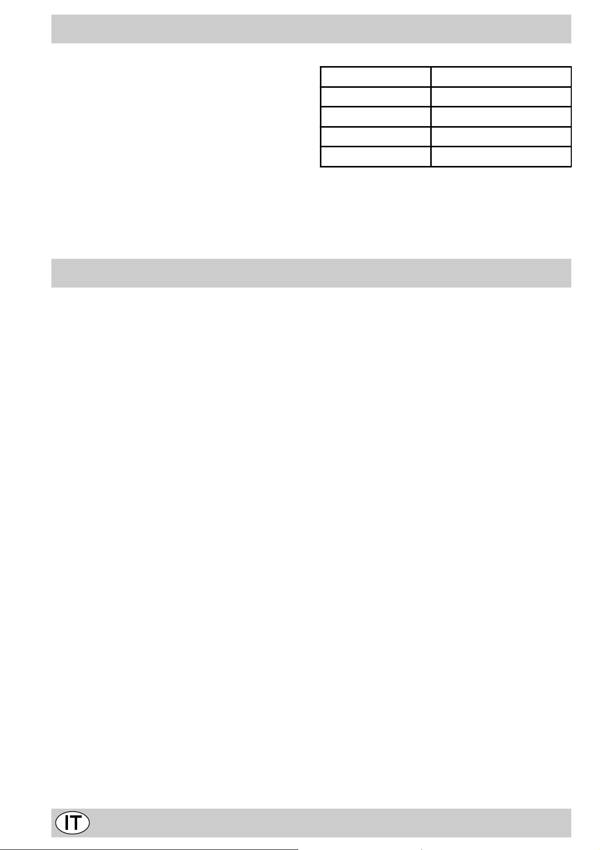
C'è qualche problema?
Bruciatore ø Diametro Recipienti(cm)
Rapido Ridotto (RR) 22 - 24
Semi Rapido (S) 16 - 20
Ausiliario (A) 10 - 14
Tripla Corona (TC) 24 - 26
Per identificare il tipo di bruciatore f ate riferimento ai disegni presenti nel paragrafo "Caratteristiche dei bruciatori
ed ugelli"
Può accadere che il piano non funzioni o non funzioni
bene. Prima di chiamare l'assistenza, vediamo che cosa
si può fare.
Innanzi tutto verificare che non ci siano interruzioni nelle
reti di alimentazione gas ed elettrica, ed in particolare i
rubinetti gas a monte del piano siano aperti.
Il bruciatore non si accende o la fiamma non è
uniforme.
Av ete controllato se:
• Sono ostruiti i fori di uscita del gas del bruciatore.
• Sono montate correttamente tutte le parti mobili che
compongono il bruciatore.
• Ci sono correnti d'aria nelle vicinanze del piano.
La fiamma non rimane accesa nelle versioni con
sicurezza.
Av ete controllato se:
• Non avete premuto a f ondo la manopola.
• Non avete mantenuto premuta a fondo la manopola
per un tempo sufficiente ad attivare il dispositivo di
sicurezza.
• Sono ostruiti i fori di fuoriuscita del gas in corrispondenza del dispositivo di sicurezza.
Il bruciatore in posizione di minimo non rimane
acceso.
Avete controllato se:
• Sono ostruiti i fori di fuoriuscita del gas.
• Ci sono correnti d'aria nelle vicinanze del piano.
• La regolazione del minimo non è corretta (Vedi paragrafo "Regolazione minimi").
I recipienti sono instabili.
Avete controllato se:
• Il fondo del recipiente è perfettamente piano .
• Il recipiente è centrato sul bruciatore.
• Le griglie sono state invertite.
Se, nonostante tutti i controlli, il piano non funziona e l'inconveniente da voi rilevato persiste, chiamate il Centro
Assistenza Tecnica Merloni Elettrodomestici più vicino, comunicando queste informazioni:
- Il tipo di guasto.
- La sigla del modello (Mod. ...) riportata sul certificato di
garanzia.
Non ricorrete mai a tecnici non autorizzati e rifiutate sempre l'installazione di pezzi di ricambio non originali.
4

La sicurezza una buona abitudine
Per garantire l’efficienza e la sicurezza di questo elettrodomestico:
• rivolgetevi esclusivamente a centri di assistenza tecnica autorizzati
• richiedete sempre l’utilizzo di parti di ricambio originali
• Questo libretto riguarda un piano di cottura da incasso
di classe3.
• L'apparecchio è concepito per uso non professionale
nelle abitazioni e le sue caratteristiche non vanno modificate.
• Le istruzioni sono valide solo per i paesi di destinazione i cui simboli figurano sul libretto e sulla targa matricola.
• La sicurezza elettrica di questo apparecchio è assicurata soltanto quando lo stesso è correttamente collegato ad un efficiente impianto di messa a terra come
previsto dalle vigenti norme di sicurezza.
T rattandosi di fonti di pericolo, evitare c he bambini e
incapaci abbiano contatti con:
- i comandi e l'apparecchio in genere;
- gli imballaggi (sacchetti, polistirolo, chiodi ecc.);
- l'apparecchio, durante e subito dopo il funzionamento,
visto il surriscaldamento;
- l'apparecchio inutilizzato (in questo caso vanno rese
innocue le parti che potrebbero essere pericolose).
V anno evitate le seguenti operazioni:
- toccare l'apparecchio con parti del corpo umide;
- l'uso quando si è a piedi nudi;
- tirare l'apparecchio o il cavo di alimentazione per staccarli dalla presa di corrente;
- operazioni improprie e pericolose;
- ostruire le aperture di ventilazione o smaltimento calore;
- che il cavo di alimentazione di piccoli elettrodomestici
finisca su parti calde dell'apparecchio;
- l'esposizione ad agenti atmosferici (pioggia, sole);
- l'utilizzo di liquidi infiammabili nei pressi;
- l'impiego di adattatori, prese multiple e/o prolunghe;
- l'impiego di pentole instabili o deformate;
- Il piano è resistente agli sbalzi di temperatura e
agli urti. Tuttavia se colpito con oggetti come
taglierini o utensili con bordi appuntiti può rompersi. In questo caso togliete subito l’alimentazione e rivolgetevi ad un centro di assistenza autorizzato.
- tentativi di installazione o riparazione senza l'intervento di personale qualificato.
Occorre assolutamente rivolgersi a personale
qualificato nei seguenti casi:
- installazione (secondo le istruzioni del costruttore);
- quando si hanno dubbi sul funzionamento;
- sostituzione della presa in caso di incompatibilità con
la spina dell'apparecchio.
Occorre rivolgersi a centri di assistenza autorizzati
dal costruttore nei seguenti casi:
- in caso di dubbio sull'integrità dell'apparecchio dopo
aver tolto l'imballaggio;
- danneggiamento o sostituzione del cavo di alimentazione;
- in caso di guasto o cattivo funzionamento, richiedendo i ricambi originali.
È opportuno effettuare le seguenti operazioni:
- solo la cottura dei cibi evitando altre operazioni;
- verificare l'integrità dopo aver tolto l'imballaggio;
- disconnettere l'apparecchio dalla rete di alimentazione elettrica in caso di cattivo funzionamento e prima di
qualsiasi operazione di pulizia o manutenzione;
- quando inutilizzato, disinserire l'apparecchio dalla rete
elettrica e chiudere il rubinetto del gas (se previsto);
- controllare sempre che le manopole siano nella posizione “•”/”o” quando l'apparecchio non è utilizzato;
- tagliare il cavo di alimentazione dopo averlo
disconnesso dalla rete elettrica quando si decide di
non utilizzare più l'apparecchio.
• Il costruttore non può essere considerato responsabile per eventuali danni derivanti da: errata installazione, usi impropri, erronei ed irragionev oli.
5
Installazione dei piani da incasso
HOOD
420
Min.
min.
650
mm. with hood
min.
700
mm. without hood
mm.
600
Min. mm.
420
Min. mm.
Le istruzioni che seguono sono rivolte all’installatore qualificato affinchè compia le operazioni di installazione
regolazione e manutenzione tecnica nel modo più corretto e secondo le norme in vigore.
Importante: qualsiasi intervento di regolazione, manutenzione etc. de ve essere eseguito con il piano elettricamente disinserito.
Posizionamento
Importante: questo apparecchio può essere installato e
funzionare solo in locali permanentemente ventilati secondo le prescrizioni delle Norme UNI-CIG 7129 e 7131
in vigore. Debbono essere osservati i seguenti requisiti:
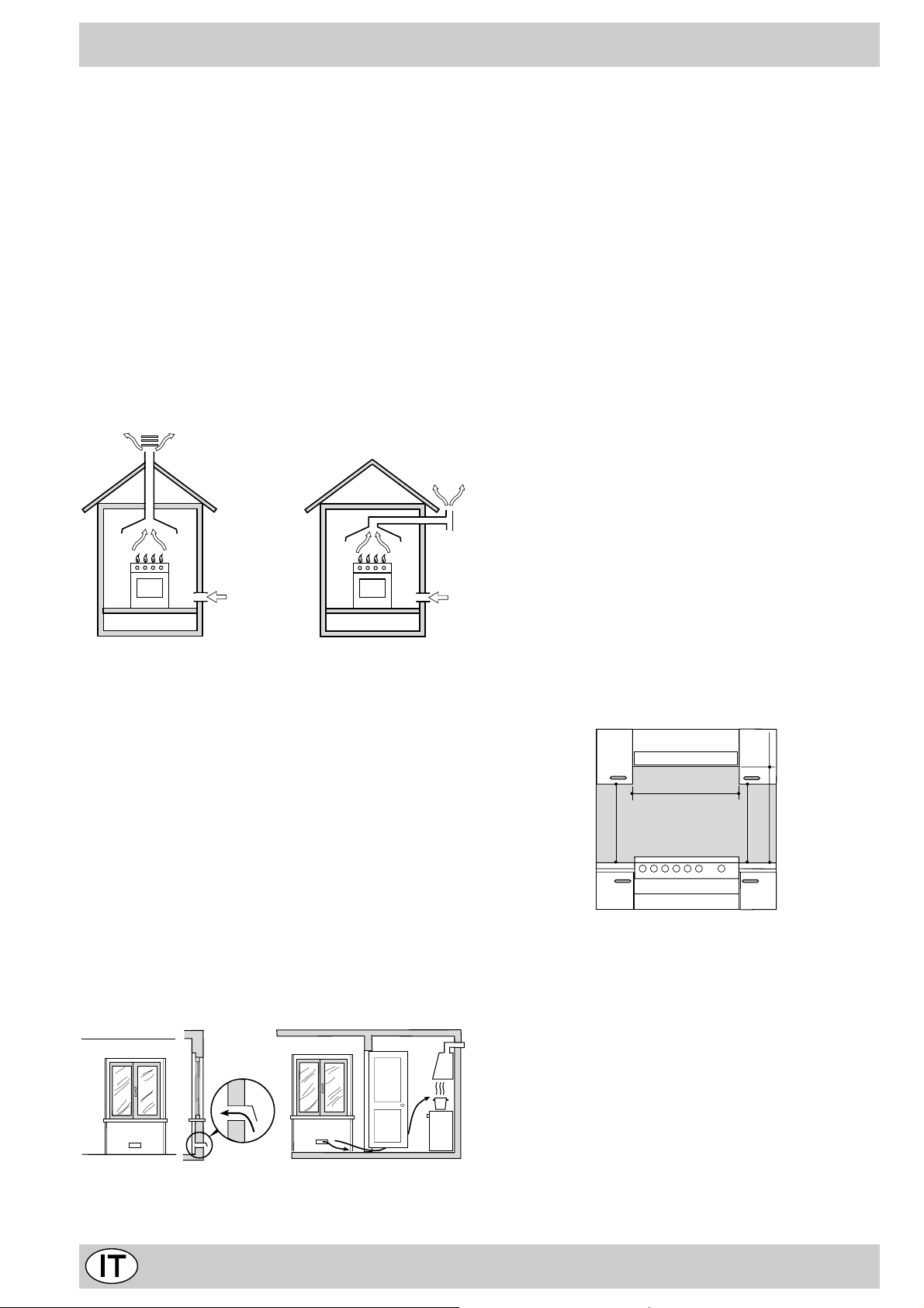
a) Il locale deve prevedere un sistema di scarico all’ester-
no dei fumi della combustione, realizzato tramite una
cappa o tramite un elettroventilatore che entri automaticamente in funzione ogni volta che si accende l’apparecchio.
In camino o in canna fumaria ramificata Direttamente all’esterno
(riservata agli apparecchi di cottura)
b) Il locale dev e pre vedere un sistema che consenta l’af-
flusso dell’aria necessaria alla regolare combustione.
La portata di aria necessaria alla combustione non deve
essere inferiore a 2 m³/h per kW di potenza installata.
Il sistema può essere realizzato prelevando direttamente l’aria dall’esterno dell’edificio tramite un condotto di
almeno 100 cm² di sezione utile e tale che non possa
essere accidentalmente ostruito. Per gli apparecchi privi sul piano di lavoro, del dispositivo di sicurezza per
assenza di fiamma, le aperture di ventilazione debbono essere maggiorate nella misura del 100%, con un
minimo di 200cm² (Fig. A). Ovvero , in maniera indiretta da locali adiacenti, dotati di un condotto di ventilazione con l’esterno come sopra descritto, e che non
siano parti comuni dell’immobile, o ambienti con pericolo di incendio, o camere da letto (Fig. B).
Particolare A Locale Locale da
adiacente ventilare
c) Un utilizzo intensivo e prolungato dell’apparecchio può
necessitare di una aerazione supplementare per esempio l’apertura di una finestra o una aerazione più efficace aumentando la potenza di spirazione meccanica
se essa esiste.
d) I gas di petrolio liquefatti, più pesanti dell’aria, rista-
gnano verso il basso. Quindi i locali contenenti bidoni
di GPL debbono prevedere delle aperture verso l’esterno così da permettere l’evacuazione dal basso delle
eventuali fughe di gas . Pertanto i bidoni di GPL, siano
essi vuoti o parzialmente pieni, non debbono essere
installati o depositati in locali o vani a livello più basso
del suolo (cantinati, ecc.). É opportuno tenere nel locale solo il bidone in utilizzo, collocato in modo da non
essere soggetto all’azione diretta di sorgenti di calore
(forni, camini, stufe, ecc.) capaci di portarlo a temperature superiori ai 50°C.
Installazione dei piani da incasso
E’ possibile l’installazione a fianco di mobili la cui altezza
non superi quella del piano di lavoro. La parete a contatto
con la parete posteriore della cucina deve essere in materiale ininfiammabile. Durante il funzionamento la parete posteriore della cucina può raggiungere una temperatura di 50°C superiore a quella ambiente. P er una corretta
installazione della cucina vanno osservate le seguenti
precauzioni:
a) I mobili situati a fianco, la cui altezza superi quella del
piano di lavoro , debbono essere situati ad almeno 600
mm. dal bordo del piano stesso.
b) Le cappe debbono essere installate secondo i requisi-
ti richiesti nei libretti istruzioni delle cappe stesse, comunque ad una distanza minima di 650 mm.
c) Posizionare i pensili adiacenti alla cappa ad un’altezza
minima dal top di 420 mm (Fig. C).
Fig. C
d) Allorchè il piano di cottura venga installato sotto un
pensile, quest’ultimo dovrà mantenere una distanza
minima dal top pari a 700 mm (millimetri) come da Fig.
C.
e) Il vano del mobile dovrà avere le dimensioni indicate
nella figura.
A
Esempi di aperture di ventilazione Maggiorazione della fessura fr a
per l’aria comburente porta e pavimento
Fig. A Fig. B
6
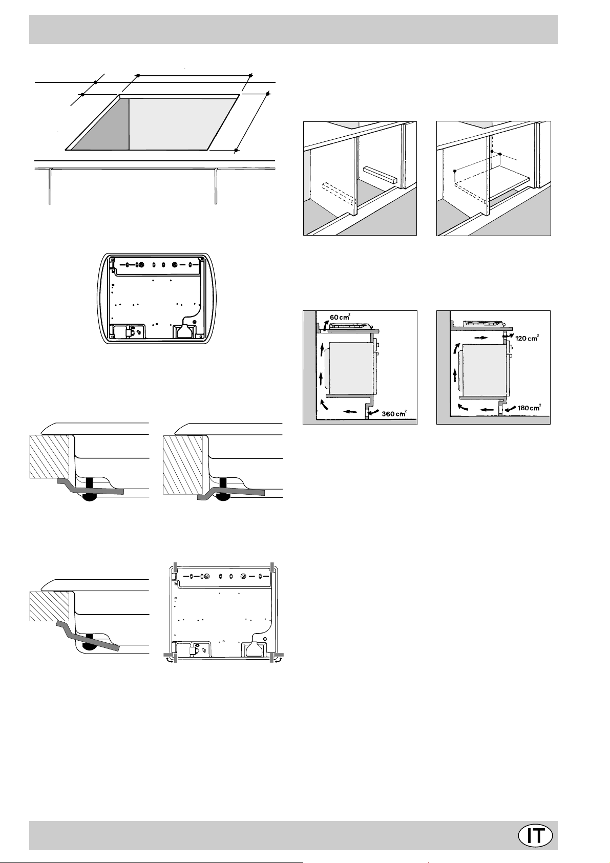
55 mm.
555 mm.
Nota: Nel caso in cui il piano sia installato su di un forno
incasso, è preferibile installare il forno in modo che appoggi su due listelli in legno; nel caso in cui sia presente
un piano continuo di appoggio questo dev e avere un’apertura posteriore di almeno 45 x 560 mm.
Prima di procedere al fissaggio al top, posizionare la
guarnizione (in dotazione) lungo il perimetro del piano
come rappresentato in figura.
Sono previsti dei ganci di fissaggio che consentono di
fissare il piano su top da 20 a 40 mm. di spessore . P er
un buon fissaggio del piano è consigliabile usare tutti i
ganci a disposizione.
Schema di fissaggio dei ganci
475 mm.
45 mm.
560 mm.
Nel caso di installazione sopra un forno da incasso senza
ventilazione forzata di raffreddamento, per consentire
un’adeguata areazione all’interno del mobile vanno garantite delle prese d’aria di ingresso e di uscita. Possibili
esempi di montaggio sono illustrati nelle figure sottostanti.
Posizione gancio per Posizione gancio per
top H=30mm top H=40mm
Avanti
Posizione gancio per Dietro
top H=20mm
N.B: Usare i ganci contenuti nella "confezione accessori"
f) Nel caso in cui il piano non sia installato su di un forno
incasso, è necessario inserire un pannello di legno
come isolamento. Esso dovrà essere posizionato ad
una distanza minima di 20 mm. dalla parte inferiore
del piano stesso.
Collegamento gas
Il collegamento dell’apparecchio alla tubazione o alla bombola del gas dovrà essere effettuato come prescritto dalle
Norme UNI-CIG 7129 e 7131, solo dopo essersi accertati
che esso è regolato per il tipo di gas con cui sarà alimentato.
In caso contrario eseguire le operazioni indicate al paragrafo “Adattamento ai div ersi tipi di gas”. Nel caso di alimentazione con gas liquido, da bombola, utilizzare regolatori di
pressione conformi alle Norme UNI-CIG 7432.
Importante: per un sicuro funzionamento, per un adeguato
uso dell’energia e maggiore durata dell’apparecchiatura, assicurarsi che la pressione di alimentazione rispetti i valori
indicati nella tabella 1 “Caratteristiche dei bruciatori ed ugelli”.
Allaccio con tubo rigido (rame o acciaio)
L’allaccio all’impianto gas deve essere eff ettuato in modo da
non provocare sollecitazioni di alcun genere all’apparecchio .
Sulla rampa di alimentazione dell’apparecchio è presente
un raccordo a “L” orientabile, la cui tenuta è assicurata da
una guarnizione. Nel caso risulti necessario ruotare il raccordo sostituire tassativamente la guarnizione di tenuta (in
dotazione con l’apparecchio). Il raccordo di entr ata del gas
all’apparecchio è filettato 1/2 gas maschio cilindrico.
Allaccio con tubo flessibile in acciaio inossidabile a
parete continua con attacchi filettati
Il raccordo di entrata del gas all’apparecchio è filettato 1/
2 gas maschio cilindrico. Utilizzare esclusivamente tubi
conformi alla Norma UNI-CIG 9891 e guarnizioni di tenuta conformi alla UNI-CIG 9264. La messa in opera di tali
tubi deve essere effettuata in modo che la loro lunghez-
7
za, in condizioni di massima estensione, non sia maggiore di 2000 mm. Ad allacciamento avvenuto assicur arsi che
il tubo metallico flessibile non venga a contatto con parti
mobili o schiacciato.
Controllo tenuta
Ad installazione ultimata controllare la perfetta tenuta di
tutti i raccordi utilizzando una soluzione saponosa e mai
una fiamma.
Collegamento elettrico
I piani dotati di cavo di alimentazione tripolare, sono predisposti per il funzionamento con corrente alternata alla
tensione e frequenza di alimentazione indicate sulla
targhetta caratteristiche (posta sulla parte inferiore del
piano). Il conduttore di terr a del cavo è contraddistinto dai
colori giallo-verde. Nel caso di installazione sopra un forno da incasso l’allaccio elettrico del piano e quello del
forno deve essere realizzato separatamente, sia per ragioni di sicurezza elettrica che per facilitare l’eventuale
estraibilità del forno.
Allacciamento del cavo di alimentazione alla rete
Montare sul cavo una spina normalizzata per il carico indicato sulla targhetta caratteristiche, nel caso di collegamento diretto alla rete è necessario interporre tra l’apparecchio e la rete un interruttore omnipolare con apertura
minima fra i contatti di 3 mm. dimensionato al carico e
rispondente alle norme in vigore (il filo di terra non deve
essere interrotto dall’interruttore). Il cavo di alimentazione deve essere posizionato in modo che non raggiunga
in nessun punto una temperatura superiore di 50°C a
quella ambiente.
Prima di effettuare l’allacciamento accertarsi che:
• la valvola limitatrice e l’impianto domestico possano
sopportare il carico dell’apparecchiatura (vedi targhetta
caratteristiche);
• l’impianto di alimentazione sia munito di efficace collegamento a terra secondo le norme e le disposizioni
di legge;
• la presa o l’interruttore omnipolare siano facilmente
raggiungibili con il piano installato.
N.B: non utilizzare riduzioni, adattatori o derivatori in quanto essi potrebbero provocare riscaldamenti o bruciature.
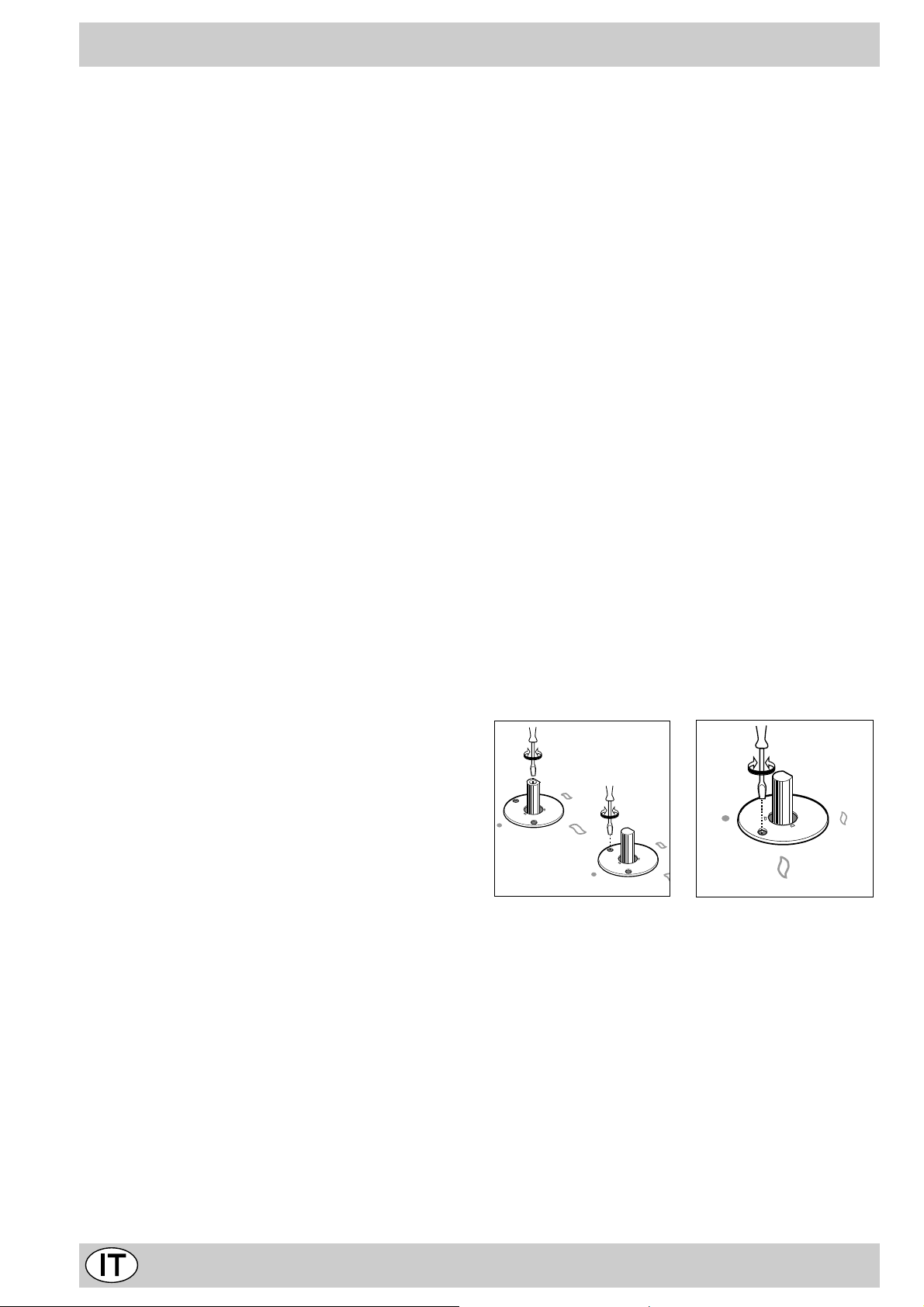
Adattamento ai diversi tipi di gas
Per adattare il piano ad un tipo di gas diverso da quello
per il quale esso è predisposto (indicato sulla etichetta
fissata nella parte inferiore del piano o sull'imballo), occorre sostituire gli ugelli dei bruciatori effettuando le seguenti operazioni:
• togliere le griglie del piano e sfilare i bruciator i dalle
loro sedi.
• svitare gli ugelli, servendosi di una chiave a tubo da
7mm. e sostituirli con quelli adatti al nuov o tipo di gas
(vedi tabella 1 “Caratteristiche dei bruciatori ed ugelli”).
• rimontare le parti eseguendo all’inv erso le operazioni.
• al termine dell’operazione, sostituite la vecchia etichetta
taratura con quella corrispondente al nuovo gas d’utilizzo, reperibile presso i Nostri Centri Assistenza Tecnica.
Qualora la pressione del gas utilizzato sia diversa (o variabile) da quella prevista, è necessario installare, sulla
tubazione di ingresso, un appropriato regolatore di pressione, secondo UNI-CIG 7430 (regolatori per gas
canalizzati).
Regolazione aria primaria dei bruciatori
I bruciatori non necessitano di nessuna regolazione dell’aria primaria.
Regolazione minimi
Regolazione minimi.
• portare il rubinetto sulla posizione di minimo;
• togliere la manopola ed agire sulla vite di regolazione
posta all’interno o di fianco all’astina del rubinetto fino
ad ottenere una piccola fiamma regolare;
N.B.: nel caso dei gas liquidi, la vite di regolazione
dovrà essere avvitata a fondo.
• verificare che ruotando rapidamente la manopola dalla posizione di massimo a quella di minimo non si abbiano spegnimenti dei bruciatori.
• negli apparecchi provvisti del dispositivo di sicurezza
(termocoppia), in caso di mancato funzionamento del
dispositivo con bruciatori al minimo aumentare la portata dei minimi stessi agendo sulla vite di regolazione.
Effettuata la regolazione, ripristinate i sigilli posti sui bypass con ceralàcca o materiali equivalenti.
8
Caratteristiche dei bruciatori ed ugelli
Tabella 1 Gas liquido Gas naturale Gas città
Bruciatore Diametro
(mm)
Rapido Ridotto
(RR)
Semi Rapido
(Medio) (S)
Ausiliario
(Piccolo) (A)
Tripla Corona
(TC)
Pressioni di
alimentazione
100 2,60 0,7 41 39 80 189 186 110 248 260 592
75 1,65 0,4 30 28 64 120 118 96 157 185 374
55 1,00 0,4 30 28 50 73 71 71 95 145 227
130 3,25 1,3 60 57 91 236 232 133 309 320 737
Potenza termica
kW (p.c.s.*)
Nomin. Ridot. (1) (mm) *** ** (mm) (mm)
Nominale (mbar)
Minima (mbar)
Massima (mbar)
By-pass
1/100
(mm)
Ugello
1/100
Portata *
28-30
20
35
g/h
37
25
45
Ugello
1/100
Portata *
l/h
20
17
25
Ugello
1/100
Portata *
l/h
8
6
15
* A 15°C e 1013 mbar-gas secco
** Propano P.C.S. = 50,37 MJ/kg
*** Butano P.C.S. = 49,47 MJ/kg
Naturale P.C.S. = 37,78 MJ/m3
Città P.C.S. = 15,87 MJ/m3
(1) Solo per apparecchi con dispositivo di sicurezza contro le fughe di gas (riferimento F).
Attenzione: Conformemente alla Direttiva CEE 90/396 l'adattabilità al Gas Città è consentita solo per apparecchi con
dispositivo di sicurezza contro le fughe di gas (riferimento F).
Per la trasformazione a gas città, richiedere il kit ugelli presso un centro di assistenza Tecnica.
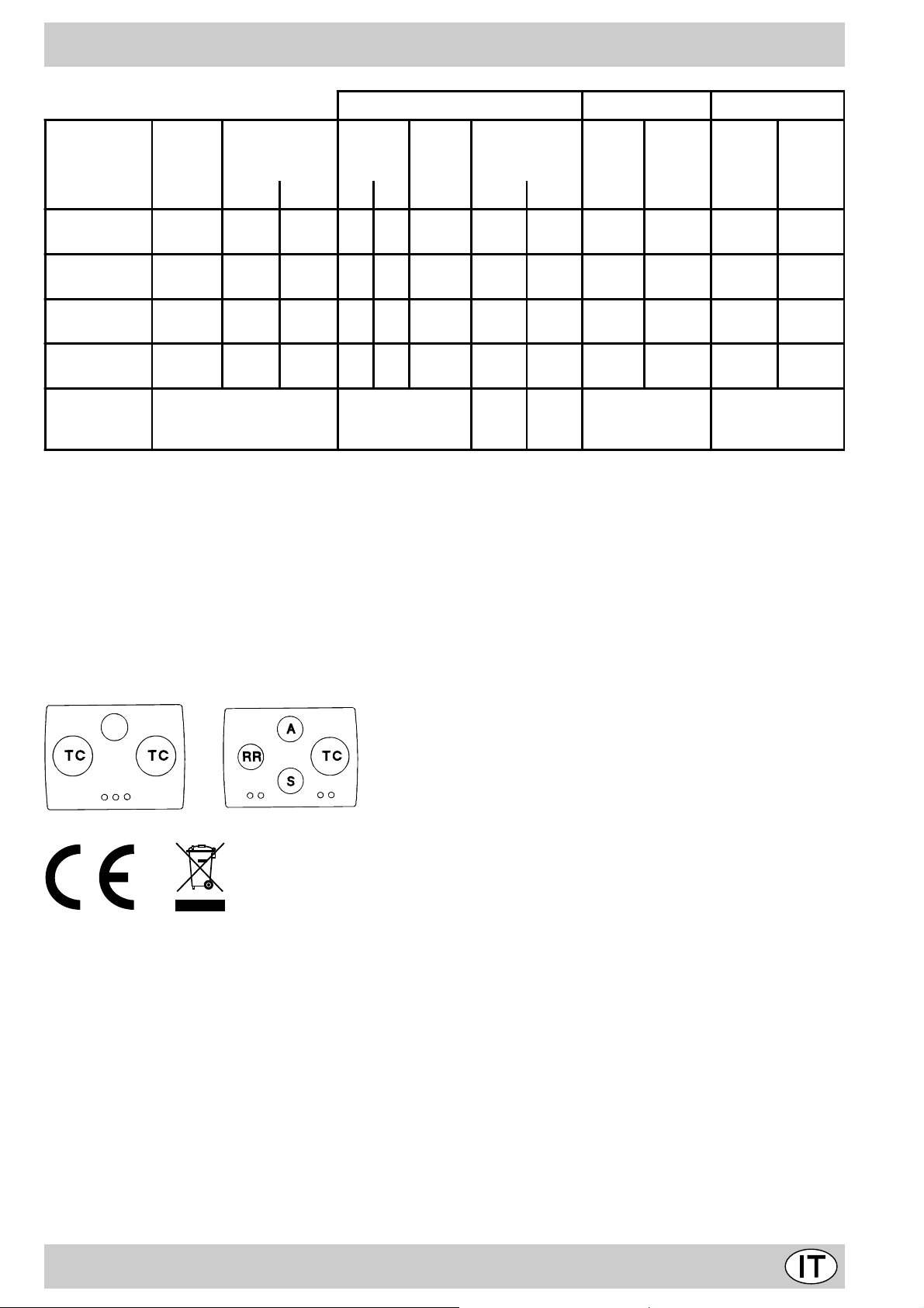
TD 730 TC... TD 740 TC...
TZ 740 TC...
S
Questa apparecchiatura è conforme alle seguenti Direttive Comunitarie:
- 73/23/CEE del 19/02/73 (Bassa Tensione) e successive modificazioni;
- 89/336/CEE del 03/05/89 (Compatibilità Elettromagnetica) e successive modificazioni;
- 90/396/CEE del 29/06/90 (Gas) e successive modificazioni;
- 93/68/CEE del 22/07/93 e successive modificazioni.
- 2002/96/CE
La direttiva Europea 2002/96/CE sui rifiuti di apparecchiature elettriche ed elettroniche (RAEE), prevede che gli elettrodomestici non debbano essere smaltiti nel normale flusso dei rifiuti solidi urbani. Gli apparecchi dismessi devono
essere raccolti separatamente per ottimizzare il tasso di recupero e riciclaggio dei materiali che li compongono ed
impedire potenziali danni per la salute e l’ambiente. Il simbolo del cestino barrato è riportato su tutti i prodotti per
ricordare gli obblighi di raccolta separata.
Per ulteriori informazioni, sulla corretta dismissione degli elettrodomestici, i detentori potranno rivolgersi al servizio
pubblico preposto o ai rivenditori.
9
Congratualtions on choosing an Ariston appliance, which you will find is dependable and easy to use . W e recommend
A
B
C
that you read this manual for best performance and to extend the life of your appliance . Thank you.
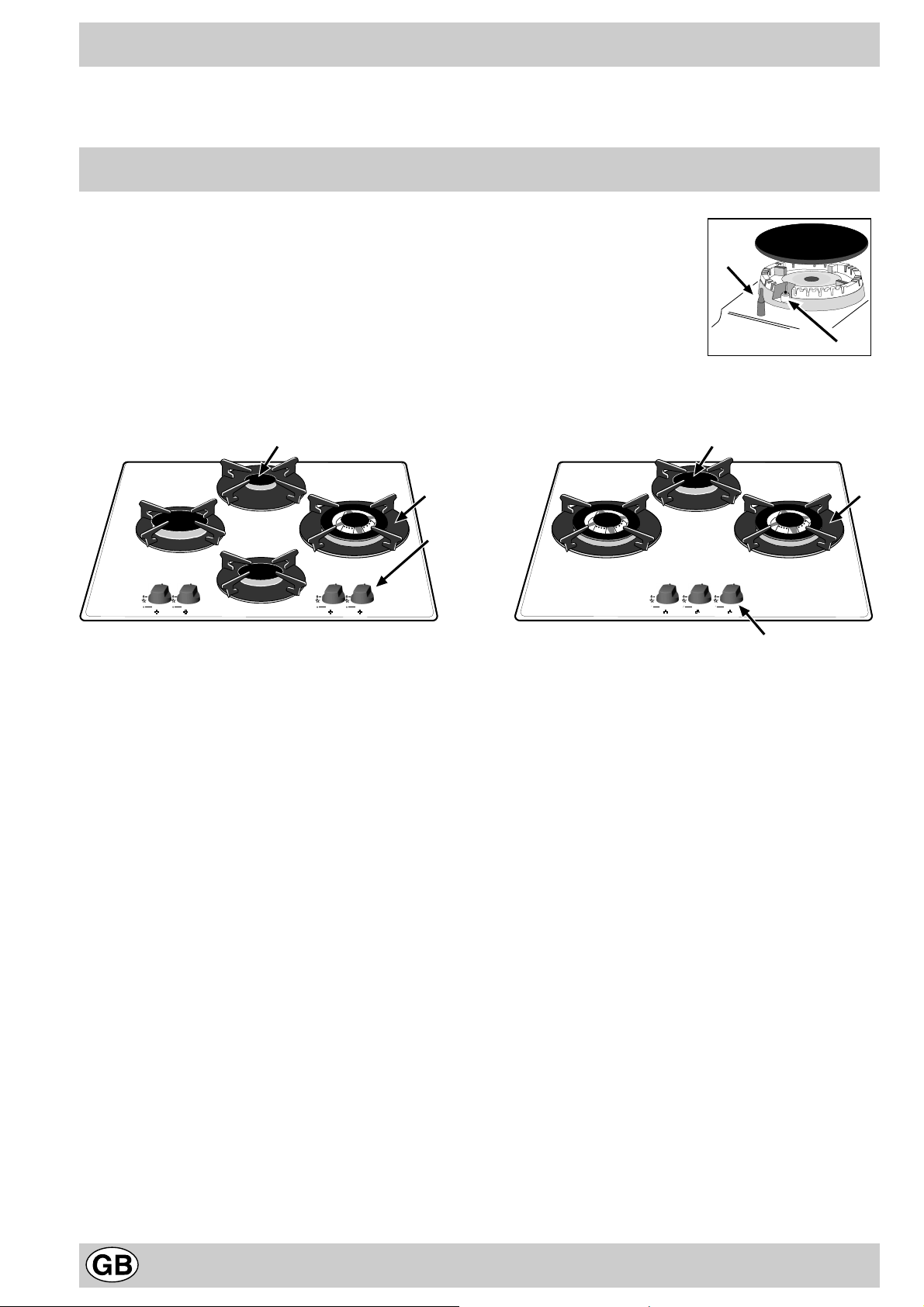
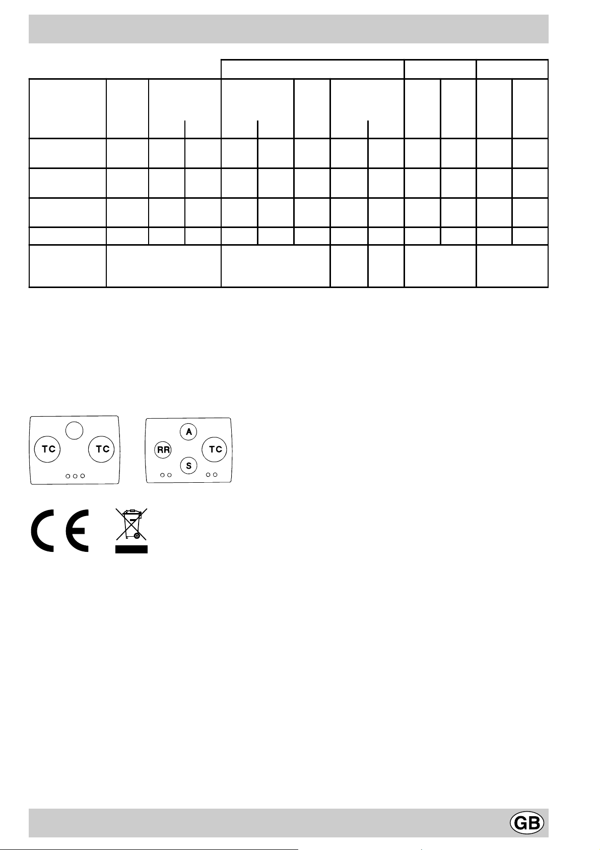
Close-up View
A. Gas Burners
B. Support Grid for Cookware
C. Control Knobs for Gas Burners
D. Ignitor for Gas Burners (only on certain models)
F. Safety Device (only on certain models) - Activates if
the flame accidentally goes out (spills, drafts, etc.),
interrupting the delivery of gas to the burner.
A
B
C
F
D
10
How T o Use Y our Appliance
The position of the corresponding gas burner is indicated
on each control knob.
Gas Burners
The burners differ in size and power. Choose the most
appropriate one for the diameter of the cookware being
used.
The burner can be regulated with the corresonding control
knob by using one of the following settings:
• Off
High
Low
How to Keep Your Cooktop in Shape
Before cleaning or performing maintenance on your
appliance, disconnect it from the electrical power supply.
To extend the life of the cooktop, it is absolutely
indispensable that it be cleaned carefully and
thoroughly on a frequent basis, keeping in mind the
following:
· Do not use steam equipment to clean the appliance.
• Enameled and glass parts must be washed with
lukewarm water without using abrasive powders or
corrosive substances that could damage them;
• The removable parts of the burners should be washed
frequently with warm water and soap, making sure to
remove caked-on substances;
• On cooktops with automatic ignition, the end of the
electronic ignition device must be cleaned carefully and
frequently, making sure that the gas holes are not
clogged;
• the top must be cleaned with glass cleaning products.
Avoid using abrasive products and abrasive sponges
that could scratch the glass.
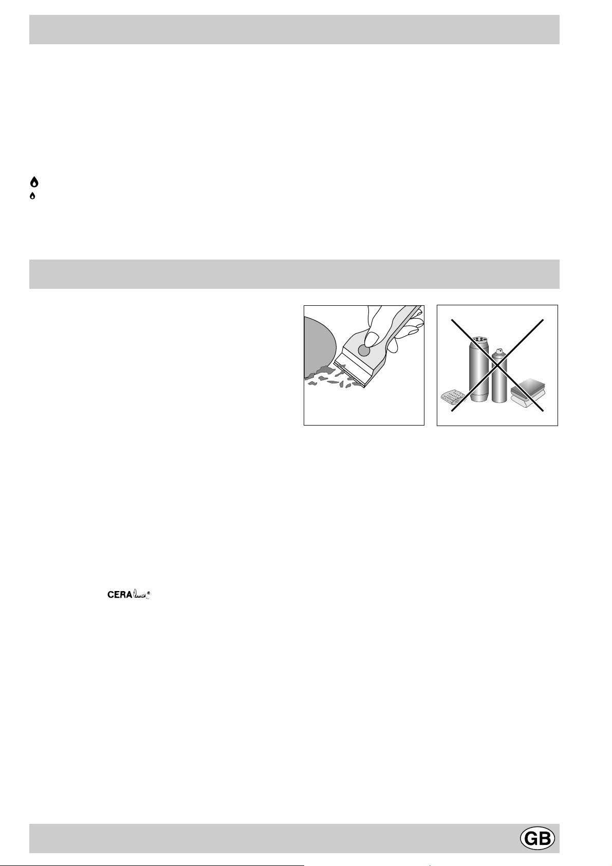
• the glass surface should be cleaned regularly with a
soultion of warm water and a non-abrasive detergent.
First, remove all food b uildup or grease with a cleaning
scraper, e .g. (not supplied) (Fig. A).
Clean the cooking surface when it is still warm with a
suitable cleaning product, then rub with a damp cloth
and dry . Sugar or foods with a high sugar content that
have melted onto the surface must be removed
immediatley with a scr aper while the cooking surface
is still hot. Do not use abrasive sponges or cleaning
products under any circumstances. This holds true f or
chemically aggressive cleaners, like oven sprays and
stain removers (Fig. B);
T o turn on one of the b urners, place a lighted match or
lighter near the burner, press the knob all the way in and
turn in the counter-clockwise direction to the "High" setting.
On those models fitted with a safety device (F), the
knob must be pressed in for about 6 seconds until the
device that keeps the flame lighted w arms up .
On those models fitted with an ignitor (D), to light a
burner, simply press the corresponding knob all the way
in and then turn it in the counter-clockwise direction to the
"High" setting, keeping it pressed in until the burner lights.
Caution: If the burner accidently goes out, turn off the
gas with the control knob and try to light it again after
waiting at least 1 minute.
To turn off a burner, turn the knob in the clockwise
direction until it stops (it should be on the “•” setting).
Fig. A Fig. B
Greasing the Taps
The taps may jam in time or they ma y become difficult to
turn. If so , the tap itself m ust be replaced.
N.B.: This operation m ust be performed by a technician
authorised by the manufacturer.
11
Practical Advice
Practical Advise on Using the Burners
For best performance, f ollo w these general guidelines:
• Use the appropriate cookware for each burner (see
table) in order to prevent the flame from reaching the
sides of the pot or pan;
• Alwasy use cookware with a flat bottom and keep the
lid on;
• When the contents come to a boil, turn the knob to
"Low".
Is there a problem?
It may occur that the cooktop does not function or does
not function properly . Before calling customer service for
assistance, lets see what can be done.
First of all, check to see that there are no interruptions in
the gas and electrical supplies, and, in particular, that the
gas valves for the mains are open.
The burner does not light or the flame is not uniform
around the burner.
Check to make sure that:
• The gas holes on the burner are not clogged;
• All of the movable parts that make up the burner are
mounted correctly;
• There are no draughts around the cooking surface.
The flame does not stay lighted on the model with
the safety device.
Check to make sure that:
• You press the knob all the way in;
• You keep the knob pressed in long enough to activate
the safety device .
• The gas holes are not clogged in the area
corresponding to the safety device .
Burner ø Cookware Diameter (cm)
Reduced Fast (RR) 22 - 24
Semi Fast (S) 16 - 20
Auxiliary (A) 10 - 14
Triple Crown (TC) 24 - 26
To identify the type of burner, refer to the designs in the
section entitled, "Burner and Nozzle Specifications".
The burner does not remain on when set to "Low".
Check to make sure that:
• The gas holes are not clogged.
• There are no draughts near the cooking surface.
• The minimum has been adjusted correctly (see the
section entitled, "Minimum Regulation").
The cookware is not stable.
Check to make sure that:
• The bottom of the cookware is perfectly flat.
• The cookware is centered correctly on the burner.
• The support grids have not been inverted.
If, despite all of these checks, the cooktop does not
function properly and problem persists, call the nearest
Merloni Elettrodomestici Customer Service Centre,
informing them of:
- The type of prob lem.
- The abbre viation used to identify the model (Mod. ...) as
indicated on the warranty.
Never call upon technicians not authorized by the
manufacturer, and refuse to accept spare parts that are
not original.
12

Safety Is a Good Habit to Get Into
T o maintain the EFFICIENCY and SAFETY of this appliance, we recommend:
• call only the Service Centers authorized by the manufacturer
• always use original Spare Parts
• This manual is for a class 3 built-in cooktop.
• This appliance is designed for non-professional use in
the home and its features and technical characteristics
must not be modified.
• These instructions are only valid for the countries the
symbols for which appear on the manual and the serial
plate.
• The electrical system of this appliance is safe only when
it is correctly connected to an adequate earthing
system, as required by current safety standards.
Prevent children and the disabled from coming into
contact or having access to the following, as they
are possible sources of danger:
- The controls and the appliance in general;
- The packaging (plastic bags, polystyrene, nails, etc.);
- The appliance, during and immediately after use given
the heat generated by its use;
- The appliance when no longer in installed (in this case,
all potentially dangerous parts must be made safe).
The following should be av oided:
- Touching the appliance with wet parts of the body;
- Using the appliance with bare feet;
- Pulling on the appliance or the power supply cord to
disconnect them from the electrical outlet;
- Improper and/or dangerous use;
- Obstructing the ventilation or heat dissipation slots;
- Allowing the power supply cord of small appliances to
come into contact with the hot parts of the cooktop;
- Exposure to atmospheric agents (rain, sun);
- Using flammable liquids nearby;
- Using adaptors, multiple outlet plugs and/or extensions;
- Using unstable or deformed cookware;
- The top made is resistant to sudden temperature
changes and shocks. However, if it is struck with
pointed utensils or objects such as cutting knives,
it may crack or break. If this occurs, disconnect
the appliance immediately from the power suppl y
and contact an authorised service centre.
- Trying to install or repair the appliance without the
assistance of qualified personnel.
The assistance of qualified personnel must be called
upon in the following cases:
- Installation (in accordance with the manufacturer's
instructions);
- When in doubt about the operation of the appliance;
- Replacement of the electrical outlet becuase it is
incompatible with the plug.
Contact service centers authorized by the
manufacturer in the following cases:
- When in doubt about the condition of the appliance
after having remov ed the packing;
- Damage to or replacement of the power supply cord;
- In the case of a breakdown or malfunction: ask for
original spare parts.
It is recommended that you follow the guidelines
below:
- Only use the appliance to cook food, avoiding all other
uses;
- Check the condition of the appliance after it has been
unpacked;
- Disconnect the appliance from the power supply in the
event of malfunction and always before cleaning or
maintenance;
- When not in use, disconnect the appliance from the
power supply and turn off the gas valve (if present);
- Always check to make sure that the control knobs are
on the “•”/”o” setting when the appliance is not in use;
- Cut the power supply cord after disconnecting it from
the electrical mains when you decide to no longer use
the appliance.
• The manufacturer will not be held liable for any
damages arising out of : incorrect installation or
improper, incorrect or unreasonable use ..
13
Installation Instructions for built-in
HOOD
420
Min.
min.
650
mm. with hood
min.
700
mm. without hood
mm.
600
Min. mm.
420
Min. mm.
The following instructions are intended for the installer so
that the installation and maintenance procedures may be
followed in the most professional and expert manner
possible. Important: Disconnect the appliance from the
electrical supply before performing any maintenance
or regulation upkeep work.
Positioning the Cooktop
Important: this unit may be installed and used only in
permanently ventilated rooms in accordance with British
Standard Codes Of Practice: B .S. 6172 / B.S. 5440, Par.
2 and B.S. 6891 Current Editions. The following
requirements must be observed:
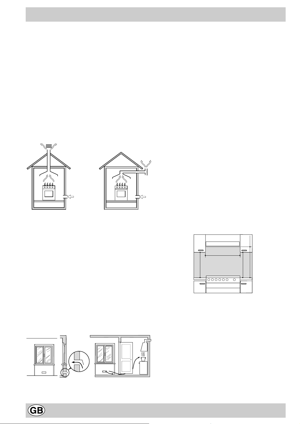
a) The room must be fitted with a ventilation system which
vents smoke and gases from comb ustion to the outside.
This must be done by means of a hood or electric
ventilator that turns on automatically each time the hood
is operated.
In a chimney stack or branched flue. Directly to the Outside
(exclusively for cooking appliances)
b) The room must also allow for the influx of the air needed
for proper combustion. The flow of air for combustion
purposes must not be less than 2 m³/h per kW of installed
capacity . The supply of said air can be effected b y means
of direct influx from the outside through a duct with a
inner cross section of at least 100 cm² which must not be
able to be accidentally block ed. Those appliances which
are not fitted with a safety device to prevent the flame
from accidentally going out must have a ventilation
opening twice the size otherwise required, i.e. a minimum
of 200cm² (Fig. A). Otherwise, the room can be vented
indirectly through adjacent rooms fitted with ventilation
ducts to the outside as described above, as long as the
adjacent rooms are not shared areas, bedrooms or
present the risk of fire (Fig. B).
Detail A Adjacent Room to be
Room Vented
c) Intensive and prolonged use of the appliance may ne-
cessitate supplemental ventilation, e.g. opening a window
or increasing the power of the air intake system (if
present).
d) Liquidified petroleum gases are heavier than air and, as
a result, settle downwards. Rooms in which LPG tanks
are installed must be fitted with ventilation openings to
the outside in order to allow the gas to escape in the
event of a leak. Therefore, LPG tanks, whether empty or
partially full, must not be installed or stored in rooms or
spaces below ground lev el (cellars, ect.). It is also a good
idea to keep only the tank currently being used in the
room, making sure that it is not near sources of heat
(ovens, fireplaces , stoves, etc.) that could raise the internal
temperature of the tank above 50°C .
Installation of Built-in Cooktops
The appliance can be installed next to furniture units which
are no taller than the top of the cooker hob. The wall in
direct contact with the back panel of the cooker must be
made of non-flammable material. During operation the
back panel of the cooker could reach a temperature of
50°C above room temperature. For proper installation of
the cooker , the f ollowing precautions must be taken:
a) If the cabinet(s) located next to the cooktop are higher
than the cooktop itself, the cabinet(s) must be installed
at least 600 mm from the edge cooktop;
b) Hoods must be installed in accordance with the
instructions contained in the installation manual for the
hoods themselves, and no less than 650 mm from the
cooktop;
c) The cabinets installed next to the hood must be located
at a height of at least 420 mm from the top, (as sho wn
in Fig. C).
Fig. C
d) Should the cooktop be installed directly under a
cupboard, the latter should be at least 700 mm
(millimetres) from the top, as shown in Fig. C.
e) The dimensions of the cutout for the appliance must
be those indicated in the figure.
A
Examples of ventilation holes Enlarging the ventilation slot
for comburant air . betw een window and floor .
Fig. A Fig. B
14
55 mm.
555 mm.
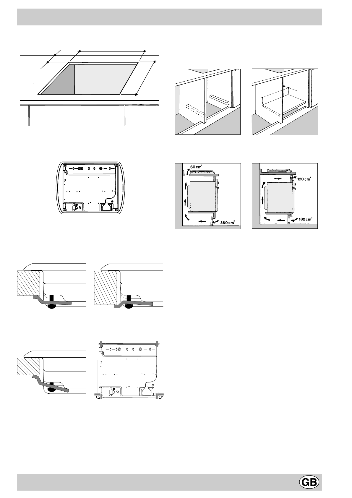
Important: When installing the cooktop above a built-in
oven, the ov en should be placed on two wooden strips; in
the case of a joining cabinet surface, remember to leave
a space of at least 45 x 560 mm at the back.
Before f astening the cooktop in place, position the seal
(supplied) along the perimeter of the countertop, as
shown in the figure.
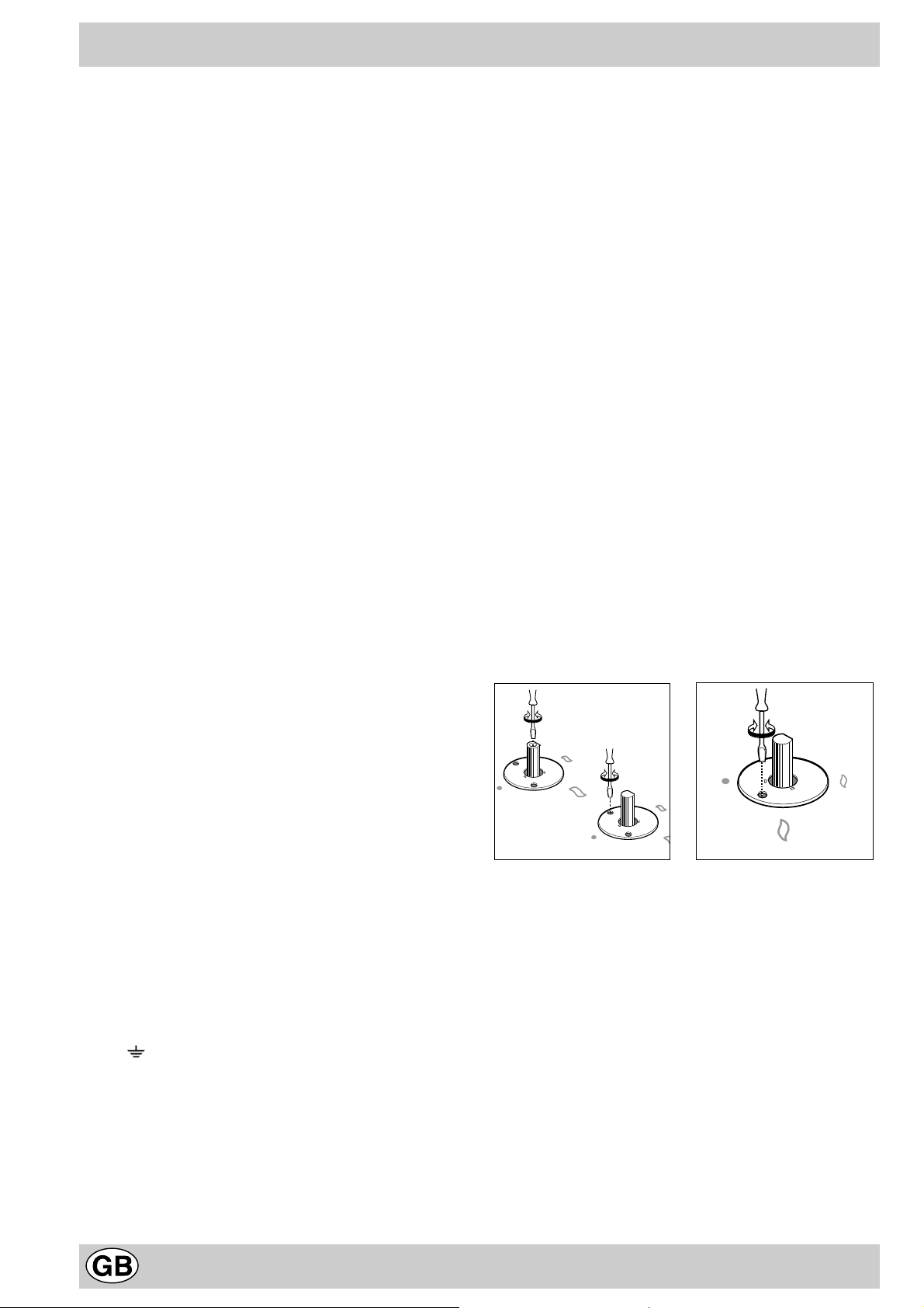
Clamps are provided to fasten the cooktop to counters
measuring from 20 to 40 mm in thickness. To fasten
the cooktop securely, it is recommended that all the
clamps be used.
Fastening Clamps - Assembly Diagram
Clamp Position f or Clamp Position f or
H=30mm top H=40mm top
Front
475 mm.
45 mm.
560 mm.
When installing the cooktop above a built-in o ven without
forced ventilation, ensure that there are air inlets and
outlets for ventilating the interior of the cabinet adequately .
Gas Connection for Cooktop
The cooktop should be connected to the gas supply by an
authorized installer. During installation of this product it is
essential to fit an approved gas tap to isolate the supply
from the appliance for the conv enience of any subsequent
removal or servicing. Connection of the appliance to the
gas mains or liquid gas tanks must be carried out
according to the safety standards currently in force, and
only after it is ascertained that it is suitable for the type of
gas to be used. If not, follow the instructions indicated in
the section entitled, “Adapting the Cooktop for Different
Types of Gas”. If the cooktop is to be connected to tanks
containing liquid gas, use pressure regulators that comply
with current safety standards.
Important: To insure that the appliance operates safety,
the gas is regulated correctly and your appliance lasts
over time, mak e sure that gas pressure lev els comply with
the indications given in Table 1, “Nozzle and Burner
Specifications”.
Clamp Position f or
H=20mm top Back
N.B: Use the clamps contained in the "accessory kit."
f) In the event the cooktop is not installed abo ve a built-
in oven, a wood panel must be inserted as insulation.
This panel must be placed at least 20 mm from the
bottom of the cooktop itself.
Gas Connection to Non-flexible Pipe
(copper or steel)
Connection to the gas source must be done in such a way
as to not create any stress points at any part of the
appliance.
The appliance is fitted with an adjustable, "L" shaped
connector and a gasket for the attachment to the gas supply .
Should this connector have to be turned, the gasket must be
replaced (supplied with the appliance).
The gas feed connector to the appliance is a threaded,
male 1/2" connector for round gas pipe.
15
Gas Connection to Flexible Steel Pipe
The gas feed connector to the appliance is a threaded,
male 1/2" connector for round gas pipe. Only use pipes,
tubes and gaskets that comply with current safety codes .
The maximum length of the flexible pipes must not e xceed
2000 mm. Once the connection has been made, ensure
that the flexible metal tube does not touch any moving
parts and is not crushed.
Check the Seal
Once the appliance has been installed, make sure all the
connections are properly sealed, using a soapy water
solution. Ne v er use a flame .
Electrical Connection
The cooktops fitted with a tripolar electrical supply cord
are designed to be be used with alternating current
according to the indications on the rating plate located
under the cooktop. The earthing wire can be identified by
its yellow-green colour .
In the case of installation over a b uilt-in electric oven,
the electrical connections for the cooktop and oven
should be independent, not only for saf ety purposes, but
also to facilitate remov al of one or both in the future.
Electrical Connection for Gas Cooktop
Fit the supply cord with a standard plug for the demand
rate indicated on the rating plate or connect it directly to
the electrical mains. In the latter case , a single pole switch
must be placed between the appliance and the mains,
with a minimum opening between the contacts of 3 mm in
compliance with current safety codes (the earthing wire
must not be interrupted by the switch). The pow er supply
cord must be positioned so that it does not reach a temperature in excess of 50°C above room temperature at
any point.
Before making the actual connection, make sure that:
• The fuse and electrical system can withstand the load
required by the appliance;
• That the electrical supply system is equiped with an
efficient earth hook-up according to the norms and
regulations prescribed by law;
• That the plug or switch is easily accessible.
Important: the wires in the mains lead are coloured in
accordance with the following code:
Green & Yellow - Earth
Blue - Neutral
Brown - Live
As the colours of the wires in the mains lead may not
correspond with the coloured markings identifying the
terminals in your plug, proceed as follows:
Connect the Green & Yellow wire to the terminal marked
“E” or or coloured Green or Green & Yellow.
Connect the Brown wire to the terminal marked “L” or
coloured Red.
Connect the Blue wire to the terminal marked “N” or
coloured Black.
Adapting the Cooktop for Different Types of Gas
To adapt the cooktop to a different type of gas than that
for which it was designed, (see the stick er under the hob
or on the packaging), the burner nozzles must be changed,
as follows:
• Remov e the pan supports and slide the burners out of
the cooktop.
• Unscre w the nozzles using a 7mm socket wrench and
replace them with those for the new type of gas. (See
table 1, “Burner and Nozzle Specifications”).
• Reassemble the parts following the instructions in
reverse order.
• On completing the operation, replace the old rating label
with the one showing the new type of gas; the sticker
is available from our Service Centres.
If the gas pressure is different than that prescribed, a
pressure regulator must be installed at the source, in
compliance with national standards governing the use of
piped gas regulators.
Regulation of Air Supply to the Burner
The burners do not need a primary air regulator.
Minimum Regulation
Minimum regulation.
• Turn the gas valve to minimum.
• Remove the knob and turn the regulator screw
(positioned either on the side of the top or inside the
shaft) clockwise until the flame becomes small but
regular.
N.B.: In the case of liquid gas, the regulation screw must
be fully screwed in (clockwise).
• Make sure that, when the knob is turned rapidly high
to low , the flame does not go out.
• In the event of a malfunction on appliances with the
security device (thermocouple) when the gas supply
is set at minimum, increase the minimum supply lev els
using the regulator screw .
Once the adjustment has been made, apply sealing wax,
or a suitable substitute, to the old seals on the by-pass .
16
Burners and Nozzle Specifications
Table 1 Liquid gas Natural gas City gas
Burner Diameter
(mm)
Thermal power
kW (p.c.s.*)
By-pass
1/100
Nozzle
1/100
Flow*
g/h
Nozzler
1/100
Flow*
(mm)
Nom. Red. (1) (mm) *** ** (mm)
Reduced F ast
(RR)
Semi Fast
(Medium) (S)
Auxiliary
(Small) (A)
100 2.60 0.7 41 39 80 189 186 110 248
75 1.65 0.4 30 28 64 120 118 96 157
55 1.00 0.4 30 28 50 73 71 71 95
Triple Crown (TC ) 130 3.25 1.3 60 57 91 236 232 133 309
Supply pressures
Nominal (mbar)
Minimum (mbar)
Maximum (mbar)
28-30
20
35
37
25
45
20
17
25
* At 15°C and 1013 mbar-dry gas
** Propane P.C.S. = 50.37 MJ/kg.
*** Butane P.C.S. = 49.47 MJ/kg.
Natural P.C.S. = 37.78 MJ/m
3
(1) Only for appliances with the security device (Ref. F).
l/h
Nozzler
1/100
(mm)
285 680
185 374
145 227
8
6
15
Flow*
l/h
TD 730 TC... TD 740 TC...
TZ 740 TC...
S
This appliance complies with the following European Economic Comm unity directives:
- 73/23/EEC of 19/02/73 (Low Voltage) and subsequent modifications;
- 89/336/EEC of 03/05/89 (Electromagnetic Compatibility) and subsequent modifications;
- 90/396/EEC of 29/06/90 (Gas) and subsequent modifications;
- 93/68/EEC of 22/07/93 and subsequent modifications.
- 2002/96/EEC
The European Directive 2002/96/EC on Waste Electrical and Electronic Equipment (WEEE), requires that old household
electrical appliances must not be disposed of in the normal unsorted municipal waste stream. Old appliances must be
collected separately in order to optimise the recovery and recycling of the materials they contain and reduce the impact
on human health and the environment. The crossed out “wheeled bin” symbol on the product reminds you of your
obligation, that when you dispose of the appliance it must be separately collected.
Consumers should contact their local authority or retailer for information concerning the correct disposal of their old
appliance.
17
Merci d'avoir choisi un produit Ariston, fiable et facile à utiliser. Pour mieux le connaître et l'utiliser le plus longtemps
A
B
C
possible, nous vous conseillons de lire attentivement ce livret. Merci.
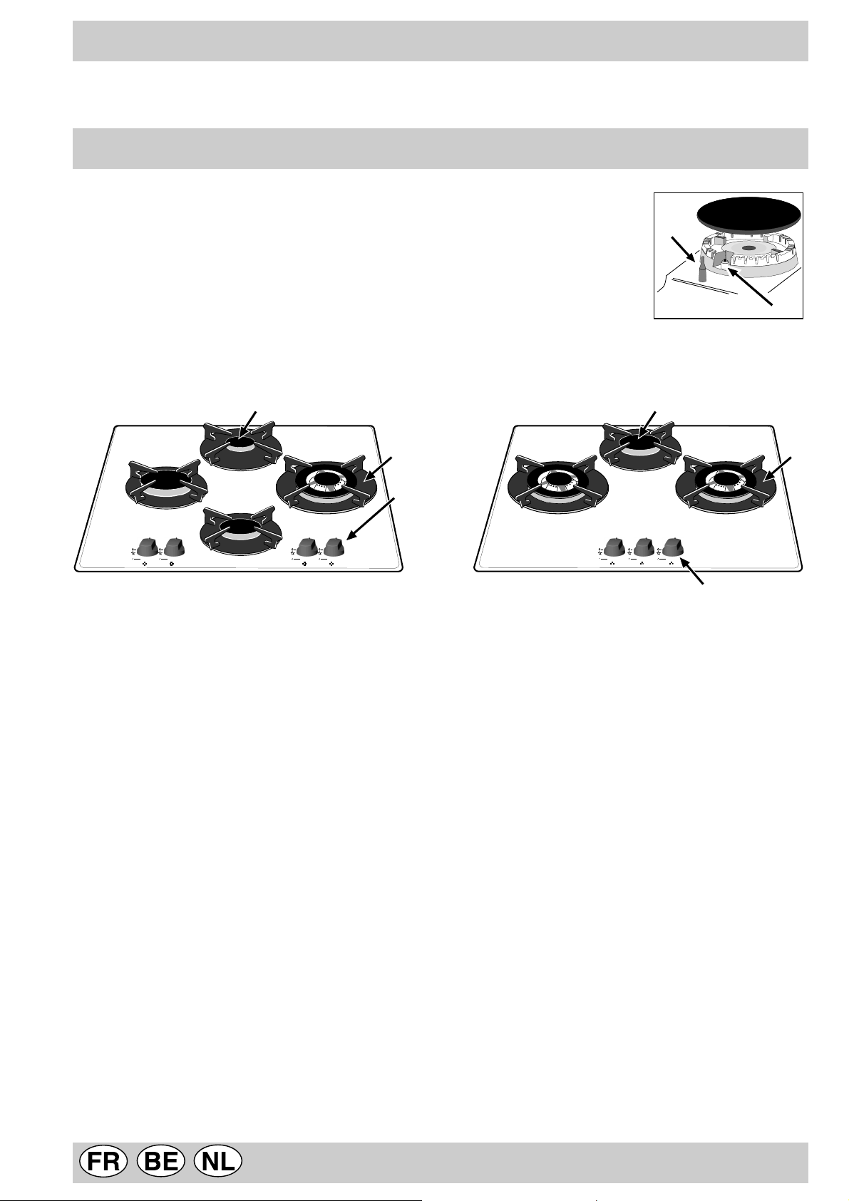
Vu de près
A. Brûleurs gaz
B. Grilles support de casseroles
C. Manettes de commande des brûleurs gaz
D. Bougie d'allumage des brûleurs gaz (présente
uniquement sur certains modèles)
F. Dispositif de sécurité (n'existe que sur certains
modèles) - Intervient en cas d'extinction accidentelle
de la flamme (débordement de liquides, courants d'air ,
...) en interrompant automatiquement l'arrivée de gaz.
A
B
C
F
D
18
Comment l'utiliser
Sur chaque manette il y a indication de la position du brûleur
gaz correspondant.
Brûleurs gaz
Ils ont des dimensions et des puissances différentes.
Choisissez-en un en fonction du diamètre de la casserole
utilisée.
Pour le réglage du brûleur choisi, servez-v ous de la manette
correspondante, comme suit:
• Eteint
Maximum
Minimum
Pour allumer un brûleur, approchez une flamme ou un
allume-gaz, appuyez à fond sur la manette correspondante
et tournez-la dans le sens contraire des aiguilles d'une montre
jusqu'à la position: puissance maximum.
Comment le garder en forme
Avant toute opér ation, coupez l'alimentation électrique de
l'appareil.
Pour prolonger la durée de vie de v otre table nettoyezla fréquemment, en n'oubliant pas que:
· pour le nettoyage, ne pas utiliser d'appareils à
vapeur
• les parties émaillées et en verre doivent être lavées à
l’eau tiède sans utiliser de poudres récurantes ou de
produits corrosifs qui pourraient les abîmer;
• les pièces amovibles des brûleurs doivent être lavées
souvent avec de l'eau chaude et du détergent en
veillant à éliminer toute incrustation possible;
• pour les tables équipées d'un dispositif d'allumage
automatique, procédez à un nettoyage fréquent de la
partie terminale des dispositifs d'allumage électronique
instantané en vérifiant que les orifices de sortie du gaz
ne soient pas bouchés;
• le plan de cuisson doit être nettoyé avec un produit
pour le nettoyage des verres. N’utilisez en aucun cas
des éponges ou produits abrasifs, qui pourraient ray er
le verre.
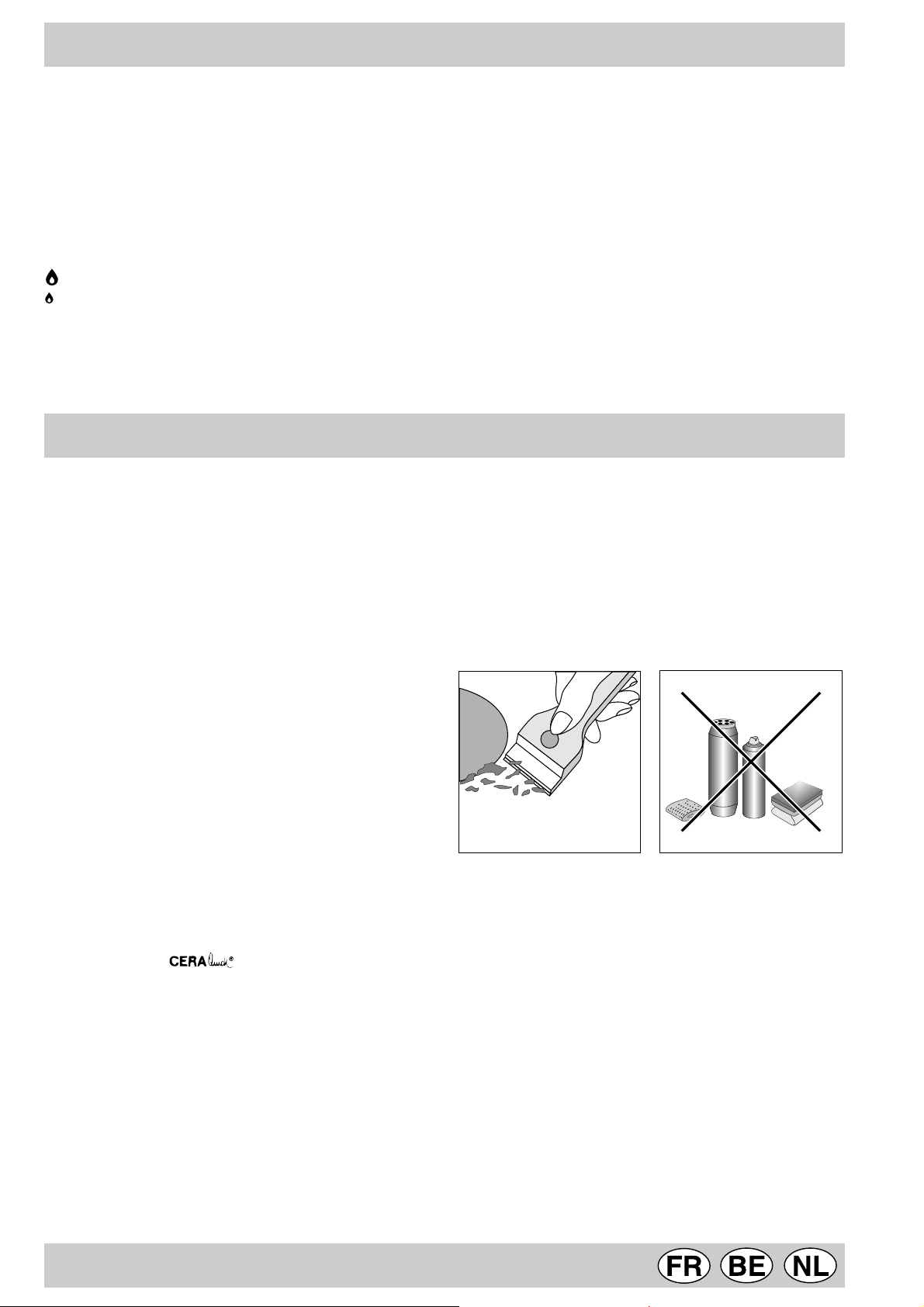
• nettoyez régulièrement la surface de la table en utilisant
une solution d'eau tiède et de détergent non abrasif.
Eliminez tout d'abord tous restes d'aliments et toutes
éclaboussures de graisse à l'aide d'un racloir comme
par exemple (n'étant pas fourni avec
l'appareil) (Fig. A).
Pour les modèles équipés de dispositif de sécurité "F",
appuyez sur la manette pendant 6 secondes environ jusqu'à
ce que le dispositif gardant automatiquement la flamme
allumée se réchauffe.
Pour les modèles équipés de bougie d'allumage "D",
pour allumer le brûleur choisi, appuyez d'abord à fond sur la
manette correspondante et tournez-la ensuite dans le sens
contraire des aiguilles d'une montre jusqu'à la position
puissance maximum, continuez à appuyer jusqu'à ce qu'il y
ait allumage.
Conseil: en cas d'extinction accidentelle de la flamme du
brûleur, fermez la manette de commande et ne tentez de
rallumer qu'au bout d'une minute au moins.
Pour éteindre le brûleur tournez la manette dans le sens
des aiguilles d'une montre jusqu'à son point d'arrêt
(correspondant au symbole “•”).
Nettoyez la table de cuisson quand elle est tiède;
utilisez un produit de nettoyage approprié, frottez av ec
un chiffon humide et essuyez. Sucre ou des aliments
à haut contenu en sucre doivent être aussitôt netto yés
quand la zone de cuisson est encore chaude à l'aide
d'un racloir. N'utilisez jamais d'éponges ou de produits
abrasifs, ni de détergents chimiques agressifs tels que
par ex emple les produits en atomiseur pour four ou les
produits détachants (Fig. B);
Fig. A Fig. B
Graissage des robinets
Il peut arriver qu'au bout d'un certain temps, un robinet se
bloque ou tourne difficilement. Il f aut alors le remplacer.
N.B.: Cette opération doit être effectuée par un
technicien agréé par le fabricant.
19
 Loading...