

Page 1
Istruzioni di montaggio
e d’uso
I
Italiano, 1 English, 9 Français, 17
E
Español, 25
D
Deutsch, 49
SL
GB F
P
Português, 33NLNederlands, 41
CAPPA ASPIRANTE
Sommario
Installazione, 2
Collegamento elettrico, 4
Funzionamento, 5
Manutenzione, 6
Avvertenze, 8
I
1
Page 2

Installazione
! Consultare anche i disegni nelle prime pagine con i
I
riferimenti alfabetici riportati nel testo esplicativo.
! Attenersi strettamente alle istruzioni riportate in
questo manuale. Si declina ogni responsabilità per
eventuali inconvenienti, danni o incendi provocati
all’apparecchio derivati dall’inosservanza delle
istruzioni riportate in questo manuale.
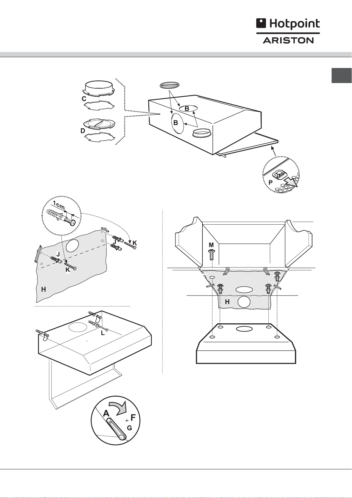
La cappa è fornita di una uscita d’aria superiore B1 e
opzionalmente anche di una uscita posteriore B2, per
lo scarico dei fumi verso l’esterno.
Scegliere la più idonea e applicare la flangia C a
corredo, chiudere sempre il foro inutilizzato con il
tappo D a corredo se previsto.
Controllare che il selettore aspirante/filtrante
(all’interno della cappa) G sia in posizione aspirante
(A). Nel caso non sia possibile scaricare i fumi e
vapori della cottura verso l’esterno, si può utilizzare la
cappa in versione filtrante montando un filtro al
carbone, i fumi e vapori vengono riciclati attraverso la
sgrigliatura anteriore posta sopra il pannello comandi.
Controllare che il selettore aspirante/filtrante sia in
posizione filtrante (F).
La cappa deve avere una distanza minima dal piano
cottura di 60 cm in caso di cucine elettriche e di 75
cm in caso di cucine a gas o miste. La cappa può
essere installata sul muro o sul fondo di un pensile; se
fornita, utilizzate la dima H per forare alla giusta
distanza, altrimenti appoggiare la cappa alla parete o
sul fondo del pensile e segnare con una matita i fori
da eseguire.
Fisaggio alle pareti
Inserire i tasselli a muro J nei fori eseguiti e due viti K
nei fori superiori, togliere la griglia e agganciare la
cappa alle 2 viti, infine, dall’interno, inserire la terza
vite L e serrarle tutte.
Fissaggio al pensile
Fissare la cappa con 4 viti M dall’interno del pensile.
2
Page 3
Installazione
I
3
Page 4

Collegamento elettrico
La tensione di rete deve corrispondere alla tensione
I
riportata sull’etichetta caratteristiche situate all’interno
della cappa. Se provvisto di spina allacciare la cappa
ad una presa conforme alle norme vigenti posta in
zona accessibile. Se sprovvisto di spina (collegamento
diretto alla rete) applicare un interruttore bipolare a
norme con una distanza dei contatti in apertura non
inferiore a 3mm (accessibile).
4
Page 5
Funzionamento
Il pannello di controllo è posto sulla parte frontale ed è
dotato di più potenze di aspirazione. Usare la potenza
di aspirazione maggiore in caso di particolare
concentrazione di vapori di cucina. Aprire sempre il
raccogli vapore N. Consigliamo di accendere
l’aspirazione 5 minuti prima di iniziare a cucinare e di
lasciarla in funzione a cottura terminata per altri 15
minuti circa.
I
5
Page 6
Manutenzione
Pulizia
I
La cappa va frequentemente pulita, sia internamente
che esternamente. Per la pulizia usare un panno
inumidito con alcool denaturato o detersivi liquidi
neutri. Evitare l’uso di prodotti contenenti abrasivi.
L’inosservanza delle norme di pulizia della cappa e
della sostituzione e pulizia dei filtri comporta rischi di
incendi.
Manutenzione
! Prima di qualsiasi lavoro di manutenzione scollegare
la cappa dalla corrente.
Filtro grassi
Può essere uno dei tipi seguenti:
Il filtro metallico deve essere pulito una volta al mese
con detergenti idonei manualmente oppure in
lavastoviglie (65°C).
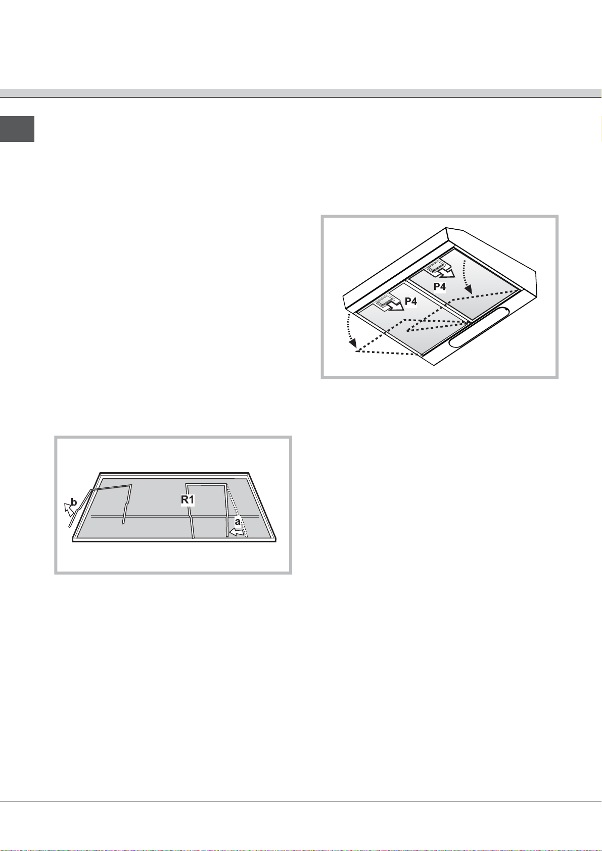
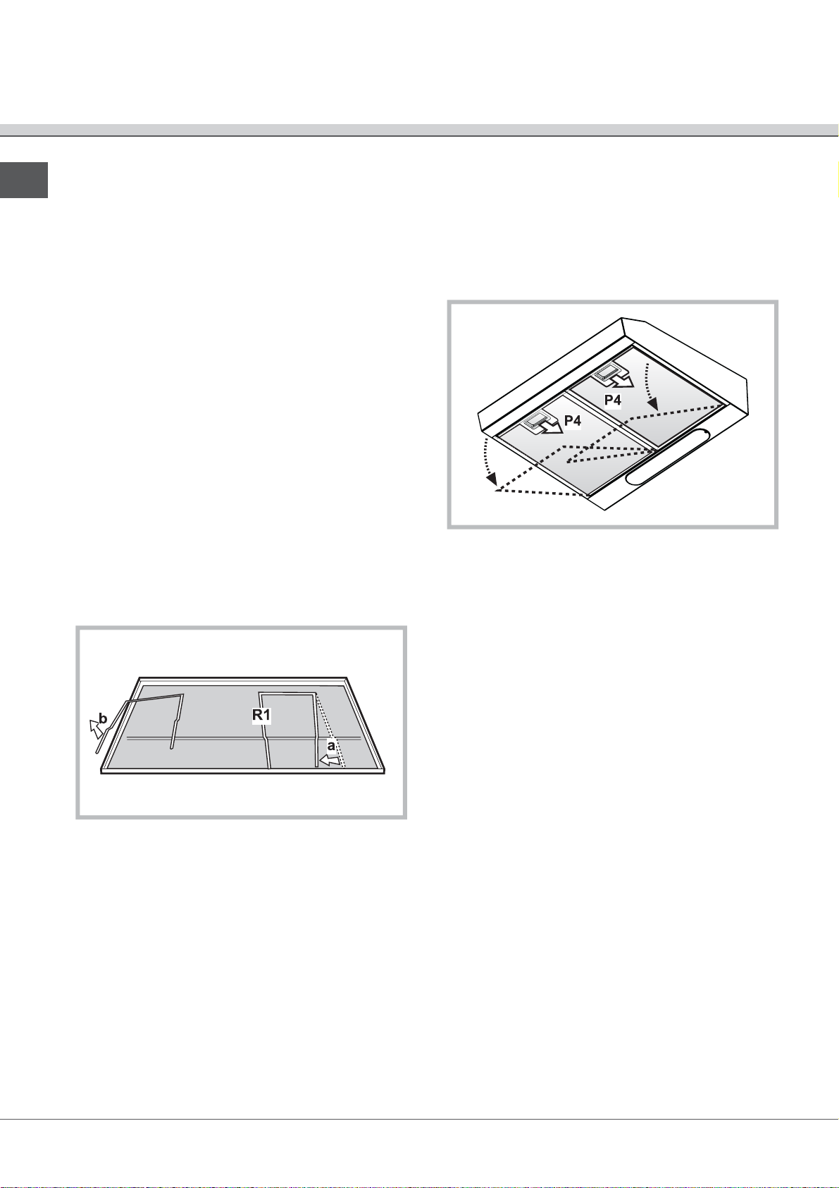
Per accedere al filtro grassi aprire la griglia tramite gli
sganci P e liberarlo dai fermi R1 o R2.
Il filtro metallico autoportante non ha griglia di
supporto, per rimuoverlo tirare le molle di sgancio P4
verso dietro ed estrarre il filtro verso il basso.
Attenzione! se lavato in lavastoviglie il filtro metallico
può cambiare il colore ma la sua capacità filtrante
rimane inalterata.
6
Page 7
Manutenzione
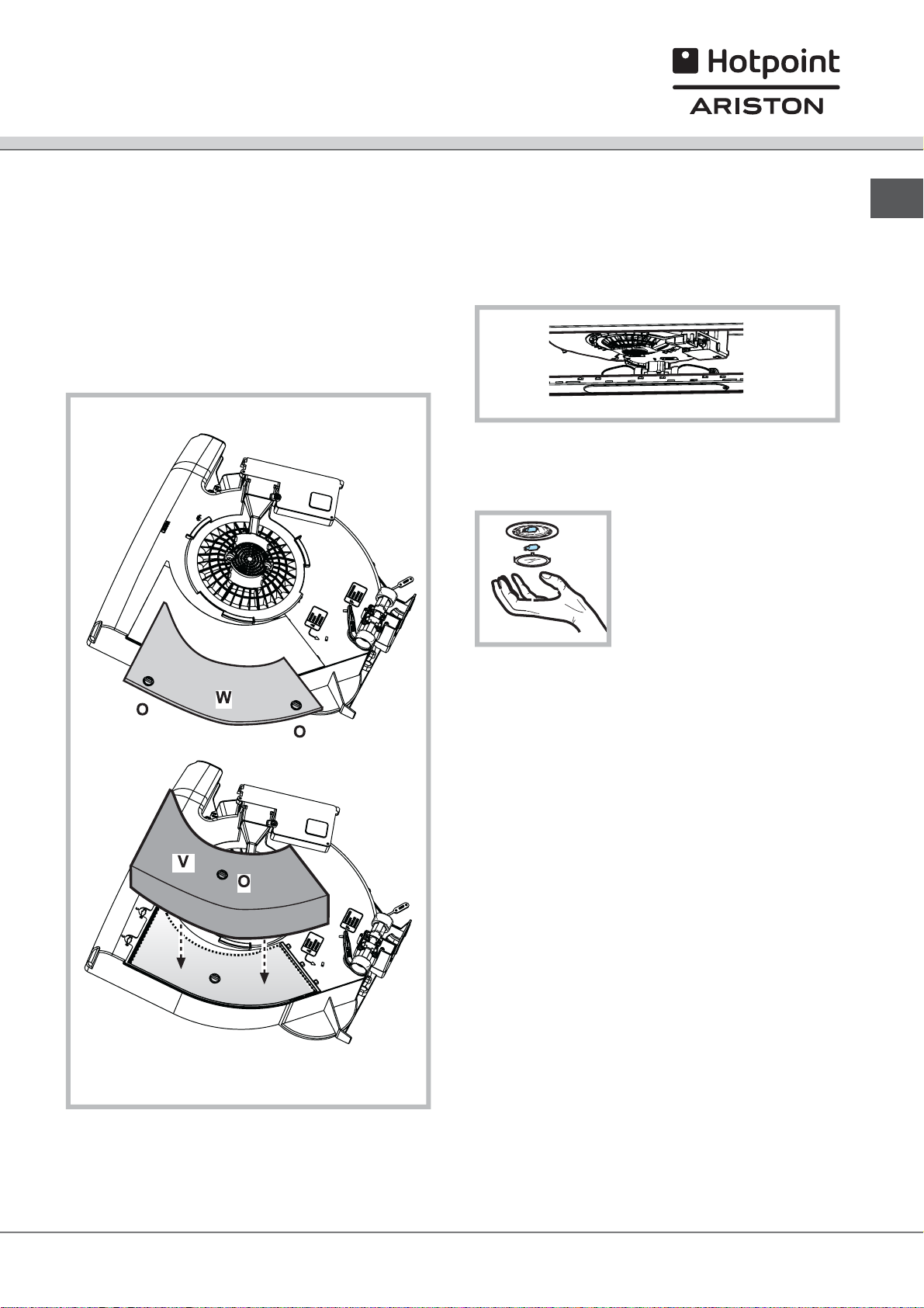
Filtro al carbone
Sostituire il filtro al carbone ogni 6 mesi.
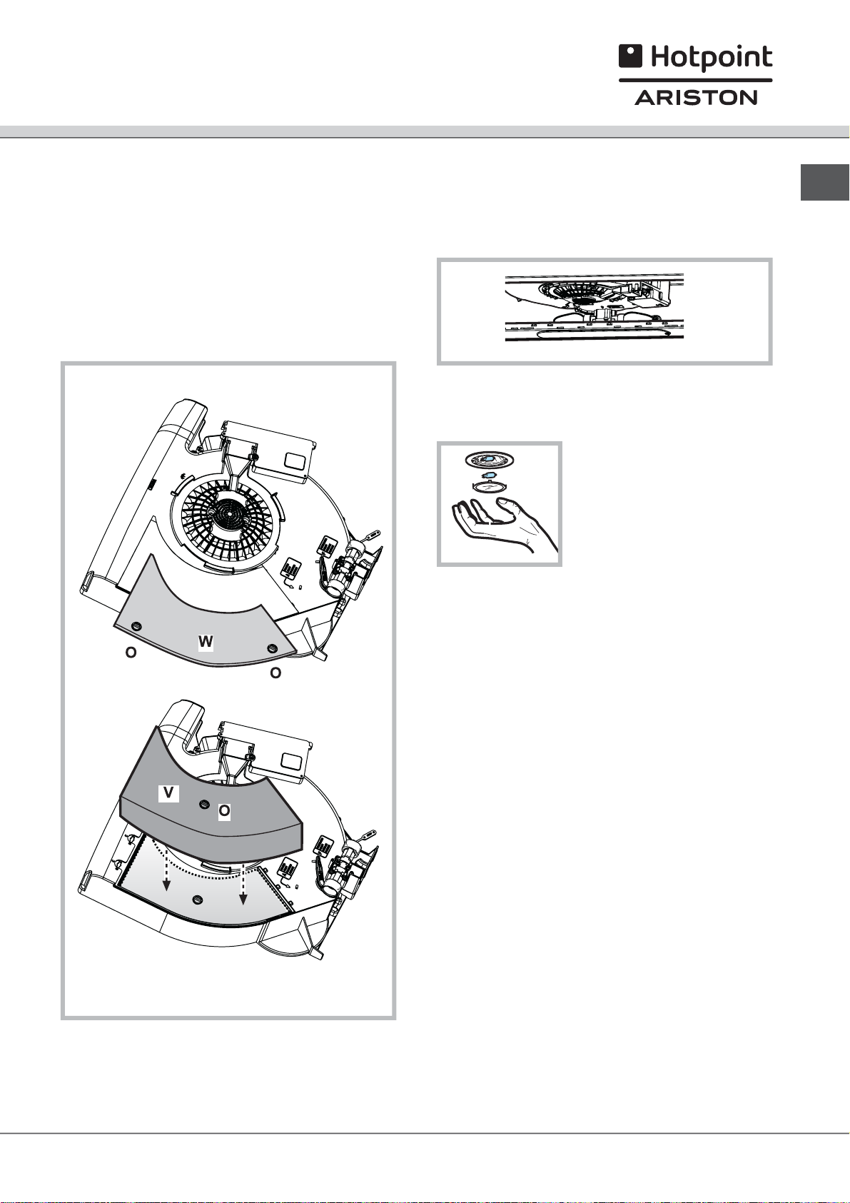
Montaggio: Rimuovere il coperchio W girando di 90° i
pomelli O.
Inserire il materassino di carbone V all’interno del vano
apposito e fissarlo girando di 90° il pomello O
,richiudere il coperchio.
Procedere in senso inverso per lo smontaggio.
Sostituzione lampade 40W
Svitare la lampada danneggiata e sostituirla con
lampada ovale ad incandescenza max 40W
E14.Togliere la griglia per accedere al vano lampade.
Sostituzione lampada alogena
Accedere al vano lampada estrarre la protezione facendo
leva con un piccolo giravite a
taglio o simile utensile.
Attenzione! Prima di toccare le lampade sincerarsi
che siano fredde.
Sostituire la lampada danneggiata.
Utilizzare solo lampade alogene da 20W max (G4),
avendo cura di non toccarle con le mani. Richiudere la
plafoniera (fissaggio a scatto).
I
7
Page 8
Avvertenze
! Mai utilizzare la cappa senza griglia correttamente
I
montata!
L’aria aspirata non deve essere convogliata in un
condotto usato per lo scarico dei fumi di apparecchi
alimentati con energia diversa da quella elettrica.
Deve essere sempre prevista un’adeguata areazione
del locale quando una cappa e apparecchi alimentati
con energia diversa da quella elettrica vengono usati
contempo-raneamente. E’ severamente vietato fare
cibi alla fiamma sotto la cappa. L’impiego di fiamma
libera è dannoso ai filtri e può dar luogo ad incendi,
pertanto deve essere evitato in ogni caso. La frittura
deve essere fatta sotto controllo onde evitare che l’olio
surriscaldato prenda fuoco. Per le misure tecniche e di
sicurezza da adottare per lo scarico dei fumi attenersi
strettamente a quanto previsto dai regolamenti delle
autorità locali competenti.
8
Page 9
Instruction mounting
and use
I
Italiano, 1 English, 9 Français, 17
E
Español, 25
D
Deutsch, 49
SL
GB F
P
Português, 33NLNederlands, 41
COOKER HOOD
Table of contents
Installation, 10
Electrical connection, 12
Operation, 13
Maintenance, 14
Caution, 16
GB
9
Page 10

Installation
GB
! Consult the designs in the front pages referenced in
the text by alphabet letters.
! Closely follow the instructions set out in this manual.
All responsibility, for any eventual inconveniences,
damages or fires caused by not complying with the
instructions in this manual, is declined.
The cooker hood has an upper air duct B1 and an
optional rear air duct B2, for external fumes exit.
Select the suitable air duct and apply the flange C
supplied, ensure to close the unused hole duct with
tap D supplied if provided.
Check that the filter/suction selector (inside the
cooker hood) G is in the suction (A) position. In the
case where it is not possible to discharge the cooking
fumes externally, the cooker hood may be used in the
filter version by fixing a carbon filter, the fumes and
vapours are recycled via the anterior grill placed
above the control panel. Check that the suction/filter
selector is in the filter (F) position.
Do not tile, grout or silicone this appliance to the wall.
Surface mounting only. Do not fix chimney flue to
furniture or fly over shelves unless the chimney flue
can be easily removed, in case maintenance is ever
required.The cooker hood must be placed at a
minimum distance of 60 cm from the cooking plane for
electric cookers and 75cm for gas or mixed cookers.
The cooker hood may be installed on the wall or on the
base of a cabinet; if supplied, use the hole gauge H to
drill the correct distance, otherwise lean the cooker
hood on the wall or on the base of the cabinet and
mark the holes with a pencil.
Wall mounting
Insert the wall screw anchors J in the drilled holes and
the two K screws in the upper drill holes, remove the
grill and hook the cooker hood to the 2 screws, finally
from the inside, insert the third screw L and lock them
all in.
Cabinet fixing
Affix the cooker hood with the 4 M screws from inside
the cabinet.
10
Page 11

Installation
GB
11
Page 12

Electrical connection
GB
The electrical tension must correspond to the tension
noted on the label placed inside the cooker hood.
Connect the electrical plug, where provided, to the an
easily accessible outlet in conformity with local
standards in force. Where an electrical plug is not
provided (for direct connection to electrical network)
place a standards approved bipolar switch with an
aperture distance of not less than 3mm (accessible)
from the contacts.
12
Page 13

Operation
The control panel is situated on the front of the cooker
hood and is equipped with various suction speeds.
Use the highest speed for situations of high level
vapour concentration in cooking. Always open the
vapour collector N. It is advisable to switch on the
suction at least 5 minutes prior to cooking and leave it
in operation for 15 minutes approximately after
cooking is terminated.
GB
13
Page 14
Maintenance
GB
! Prior to any maintenance operation ensure that the
cooker hood is disconnected from the electrical outlet.
Cleaning
The cooker hood should be cleaned regularly
internally and externally. For cleaning use a cloth
moistened with denatured alcohol or neutral liquid
detergents. Avoid abrasive detergents.
Failure to carry out the basic standards of the cleaning
of the cooker hood and replacement of the filters may
cause fire risks.
Grease Filter
May be one of the following types:
Metallic filter must be cleaned once a month with
suitable detergents either by hand or in dishwasher
(65°C).
When washed in a dish washer, the grease filter may
discolour slightly, but this does not affect its filtering
capacity.
In order to remove the grease filter open the grill via
the P hooks and free the R1 or R2 stoppers.
The self-supporting metal filter does not include a
support grill, in order to remove the filter – pull the
release springs P4 backwards and slide the filter
downwards.
Attention! the metal filter may discolour if washed in
dishwasher but the filtering performance is unaltered.
14
Page 15
Maintenance
Carbon Filter
To be replaced every 6 months
Mounting: Remove the cover W by rotating the O
knobs to 90° fit the carbon filter V and fix by rotating
the O knobs to 90°, then close the cover. Proceed in
the inverse for dismounting.
Replacing lightbulbs 40W
Unscrew the damaged light bulb and replace with an
incandescent oval light bulb with a maximum of 40W
E14. Remove the grill in order to reach the light bulb
area.
Replacing the hologen bulbs
Access the light compartment –
extract the lamp cover by
levering it off with a small
screwdriver or similar tool.
GB
Warning! Prior to touching the light bulbs ensure
they are cooled down. Replace the damaged light
bulb. Only use halogen bulbs of 20W max (G4),
making sure you do not touch them with your hands.
Close the lamp cover (it will snap shut).
15
Page 16

Caution
GB
! This appliance is designed to be operated by adults.
Children should not be allowed to tamper with the
controls or play with the appliance.
Do not use the cooker hood where the grill is not
correctly fixed! The suctioned air must not be
conveyed in the same channel used for fumes
discharged by appliances powered by other than
electricity. The environment must always be
adequately aerated when the cooker hood and other
appliances powered by other than electricity are used
at the same time. Flambé cooking with a cooker hood
is prohibited. The use of a free flame is damaging to
the filters and may cause fire accidents, therefore free
flame cooking must be avoided. Frying of foods must
be kept under close control in order to avoid
overheated oil catching fire. Carry out fumes
discharging in accordance with the regulations in force
by local laws for safety and technical restrictions.
16
Page 17

Description de montage
et mode l’emploi
I
Italiano, 1 English, 9 Français, 17
E
Español, 25
D
Deutsch, 49
SL
GB F
P
Português, 33NLNederlands, 41
HOTTE ASPIRANTE
Sommaire
Installation, 18
Branchement électrique, 20
Fonctionnement, 21
Entretien, 22
Attention, 24
F
17
Page 18

Installation
! Consulter les dessins de la première page avec les
F
références alphabétiques que l’on retrouvera dans le
texte explicatif.
! Suivre strictement les instructions de cette notice. Le
constructeur décline toute responsabilité pour tous les
inconvenients, dommages ou incendies provoquès à
l’appareil et dus à la non observation des instructions
de la présente notice.
La hotte est fournie avec une sortie d’air supérieure
B1 et en option une sortie arrière B2, prévue pour
l’évacuation des fumées vers l’extérieur. Selon la
solution retenue, appliquer la bride C fournie, boucher
dans tous les cas le trou inutilisé avec le bouchon D
fourni.
Controler que le selecteur mode aspirant/filtrant
(situé a l’intérieur de la hotte) G est en position
aspirante (A). Dans le cas où il est impossible
d’évacuer vers l’extérieur les fumées et vapeurs de
cuisson, vous pouvez alors utiliser la hotte en version
filtrante en montant le filtre a charbon. Les fumées et
vapeurs seront recyclées à travers la grille avant
située au dessus du panneau de commandes.
Controler que le selecteur aspirante/filtrant est en
position filtrante (F).
Si vous possédez un plan de cuisson entièrement
électrique, la hotte doit etre installée a une distance
de 60 cm, de 75 cm dans le cas d’un plan de cuisson
mixte ou a gaz. La hotte peut etre installée sur un mur
ou sur le fond d’un meuble; s’il est fourni, utiliser le
gabarit de pose H de facon a percer correctement les
trous, sinon, appuyer la hotte sur le mur ou sur le fond
du meuble et à l’aide d’un crayon noir, repérer l’endroit
où percer les trous.
Fixation murale
Inserer les chevilles J dans les trous et les 2 vis K
dans les trous supérieurs. Retirer la grille et accrocher
la hotte aux 2 vis, ensuite, depuis l’intérieur,
positionner la troisième vis L enfin serrer toutes les vis.
Fixation sous un meuble
Fixer la hotte avec les 4 vis M à l’intérieur du meuble.
18
Page 19

Installation
F
19
Page 20

Branchement électrique
La tension du réseau doit correspondre à la tension
F
indiquée sur l’étiquette des caractéristiques située
dans la hotte. Si la hotte est fournie avec une fiche, la
raccorder à une prise accessible conforme aux
normes en vigueur. Si la hotte est fournie sans fiche
( branchement direct sur le réseau), la raccorder à un
interrupteur bipolaire normalisé ayant une distance
des contacts supérieure à 3 mm (accessible).
20
Page 21

Fonctionnement
Le panneau de controle se trouve sur la partie avant
de la facade et est doté de differentes vitesses
d’apiration. Utiliser la puissance d’aspiration maximale
en cas d’odeurs ou de vapeur importantes. Dégager
le panneau frontal N. Nous vous conseillons de
mettre la hotte en route 5 minutes avant de
commencer a cuisiner et de la laisser fonctionner
environ 15 minutes après la cuisson.
F
21
Page 22

Entretien
! Veillez a débrancher la hotte du réseau electrique
F
avant toute intervention sur celle- ci.
Nettoyage
La hotte doit etre regulièrement nettoyée à l’intérieur et
à l’extérieur. Pour le nettoyage, utiliser un chiffon
humide imbibé d’alcool dénaturé ou de détergents
liquides neutres. Eviter d’utiliser des produits abrasifs.
Le non respect des règles de nettoyage de la hotte,
de la substitution et du nettoyage des filtres comporte
des risques d’incendie.
Filtre a graisse
Il peut s’agir d’un des modèles suivants:
Le filtre mécanique doit etre nettoyé a la main une
fois par mois a l’aide de détergents adaptés. Vous
pouvez également le passer au lave vaisselle.(65°C).
Pour accéder au filtre a graisse ouvrir la grille a
l’aide des loquets P et la sortir de ses fixations R1 ou
R2.
Le filtre métallique autoportant n’a pas de grille de
support, pour l’enlever, tirer les ressorts de
décrochage P4 vers l’arrière et extraire le filtre vers le
bas.
Attention! Si lavé en lave vaisselle le filtre métallique
peut changer de couleur mais son efficacité filtrante
reste inchangée.
22
Page 23

Entretien
Filtre au charbon
Changer tous les 6 mois.
Montage: Enlever le couvercle W en tour nant les
pommeaux O de 90°
Insérer le petit matelas à charbon V à l’intérieur du
logement approprié et le fixer en tournant le pommeau
O de 90°, refermer le couvercle.
Procéder en sens inverse pour le démontage.
Changement de l’ampoule 40W
Dévisser l’ampoule grillée et la remplacer par une
ampoule ovale a incandescence max 40W E14.
Enlever la grille pour accéder au compartiment de la
lampe.
Replacing the hologen bulbs
Accéder au logement de la
lampe – sortir la protection en
utilisant un petit tournevis à
lame plate ou tout autre outil
similaire.
F
Attention! Avant de toucher les lampes, assurez-vous
qu’elles soient froides. Remplacer la lampe
endommagée. Utiliser uniquement des lampes
halogènes 20W maximum (G4), en ayant soin de ne
pas les toucher avec les mains. Refermer le plafonnier
(fixation par encliquetage).
23
Page 24

Attention
! Ne jamais utiliser la hotte sans avoir installé
F
correctement la grille!
L’air aspiré ne doit pas etre expulsé dans un conduit
utilisé pour l’échappement des fumées d’appareils
alimentés avec une énergie autre que l’énergie
électrique. Il faut prévoir une bonne aération du local
lorsque l’on utilise simultanément une hotte et des
appareils alimentés avec une autre énergie que
l’electricité. Il est strictement défendu de faire flamber
des aliments sous la hotte. Toute flamme sous la hotte
peut endommager les filtres et causer un incendie. La
friture doit etre surveillée pour éviter que l’huile
surchauffée ne s’enflamme. Pour des raisons
techniques et de sécurité veuillez suivre
scrupuleusement les réglementations locales relatives
à l’évacuation des fumées.
24
Page 25

Montaje y modo
de empleo
I
Italiano, 1 English, 9 Français, 17
E
Español, 25
D
Deutsch, 49
SL
GB F
P
Português, 33NLNederlands, 41
CAMPANA EXTRACTORA
Indice
Instalación, 26
Conexión eléctrica, 28
Funcionamiento, 29
Mantenimiento, 31
Advertencias, 32
E
25
Page 26

Instalación
! Consulte tambien los dibujos de las primeras
E
páginas con las referencias alfabéticas del texto
explicativo. Aténgase estrictamente a las instrucciones
del presente manual.
! Se declina cada responsabilidad por eventuales
inconvenientes, daños o incendios provocados al
aparato originados por la inobservancia de las
instrucciones colocadas en este manual.
La campana consta de una salida de aires superior
B1 y opcionalmente de una salida posterior B2, para
la descarga de humos hacia el exterior. Elija la más
adecuada y aplique la arandela C adjunta , cierre
siempre el orificio inutilizado con la tapa D adjunta si
fuera necesario.
Controle que el selector aspirante/filtrante (en el
interior de la campana) G esté en posición aspirante
(A) En caso de que no fuera posibledescargar los
humos y los vapores de la cocción hacia el exterior, se
puede utilizar la campana en versión filtrante
montando un filtro al carbón, los humos y los
vapores son reciclados a través de larejilla anterior
situado encima del panel de mandos. Controle que el
selector aspirante/filtrante esté en posición filtrante
(F).
La campana tiene que tener una distancia mínima de
los fuegos de 60 cm en las cocinas eléctricas y de 75
cm en las cocinas a gas o mixtas. La campana puede
ser instalada en el muro o en el fondo del armario
pensil; si está incluida , utilice la placa H para realizar
los orificios a la distancia adecuada, o bien apoye la
campana a la pared o en el fondo del armario pensil
señale con el lapicero los orificios que debe realizar.
Sujeción a la pared
Introduzca las escarpias J en los orificios que ha
realizado anteriormente y dos tornillos K en los
orificios superiores, quite la rejilla y enganche la
campana en los dos tornillos, introduzca el tercer
tornillo L y apríetelos todos.
Sujeción al armario pensil
Sujetar la campana con 4 tornillos M en el interior del
armario pensil.
26
Page 27

Instalación
E
27
Page 28

Conexión eléctrica
La corriente de la red debe corresponder a la
E
corriente señalada en la etiqueta de las características
situada en el interior de la campana. Si contiene un
enchufe conecte la campana a una toma de corriente
conforme a las normas vigentes situada en una zona
accesible. Si contiene un enchufe(conexión directa a
la red, aplique un interruptor bipolar a norma con una
distancia de los contactos en abertura no inferior a 3
mm ( accesible.).
28
Page 29

Funcionamiento
El panel de control está situado en la parte frontal y
está dotado de más potencias de aspiración. Use la
potencia de aspiración mayor en caso de una gran
concentración de vapores en la cocina. Abra siempre
el recoge vapores N. Aconsejamos encender la
aspiración cinco minutos antes de empezar a cocinar
y dejarla encendida 15 minutos después de haber
terminado de cocinar.
E
29
Page 30

Mantenimiento
! Antes del mantenimiento desconecte la campana de
E
la corriente eléctrica.
Limpieza
La campana debe ser limpiada con frecuencia tanto
externamente como internamente. Para limpiarla use
un paño empapado de alcohol desnaturalizado y
detergentes líquidos neutros. Evite el uso de
productos que contengan abrasivos. Si no se
respetan las normas de limpieza de la campana y del
cambio y limpieza de los filtros puede haber riesgo de
incendio.
Filtro grasas
Puede ser uno de los siguientes tipos:
El filtro metálico debe limpiarse una vez al mes con
detergentes adecuados a mano o bien en el
lavavajillas a 65°C.
Para acceder al filtro grasas abra la rejilla con los
enganches P y sáquelo de los topes R1 y R2.
El filtro metálico autoportante no tiene rejilla para
sujetarlo, para sacarlo tire de los muelles de
desenganche P4 hacia atrás y saque el filtro hacia
abajo.
Atención!
Si usted lava el filtro metálico en el lavavajillas , este
puede cambiar de color pero su capacidad filtrante
permanecerá inalterada.
30
Page 31

Mantenimiento
Filtro al carbón
Cambiarlo cada 6 meses.
Montaje: Quite la tapa W girando 90° los pomos O.
Introduzca la esponja de carbón V en su sitio y
sujétela girando 90° el pomo O, vuelva a cerrar la
tapa.
Realice esta operación al revés para desmontarla.
Substituciòn làmparas 40W
Desatornille la lámpara dañada y cámbiela con una
lámpara oval incandescente Max 40W E14. Quite la
rejilla para acceder al lugar donde se encuentran las
lámparas.
Substituciòn làmparas halógenas
Extraer la protección haciendo
palanca con un pequeño
destornillador de boca plana o
una herramienta similar.
Sustituir la lámpara dañada.
E
Utilizar sólo lámparas halógenas de 20W máx (G4)
prestando atención en no tocarlas con las manos.
Cerrar el plafón (fijación a presión).
31
Page 32

Advertencias
! No use nunca la campana sin haber montado
E
correctamente la rejilla.
El aire aspirado no debe ser canalizado en un
conducto usado para la descarga de humos de
aparatos alimentados con energía que no sea
eléctrica.Hay que realizar anteriormente una
adecuada aireación del local cuando se usen al
mismo tiempo la campana y los aparatos alimentados
con otra energía que no sea eléctrica. Está
rigurosamente prohibido cocinar alimentos a la llama
debajo de la campana. El empleo de la llama libre
daña los filtros y puede provocar incendios, por lo
tanto debe evitarse en cualquier caso. Cuando se
fríen los alimentos se debe tener cuidado de que el
aceite no se caliente en exceso y se incendie. Para
las medidas técnicas y de seguridad que haya que
adoptar para la descarga de los humos aténgase
rigurosamente a lo que diga el reglamento de las
autoridades locales competentes.
32
Page 33

Instruções para
montagem e utilização
I
Italiano, 1 English, 9 Français, 17
E
Español, 25
D
Deutsch, 49
SL
GB F
P
Português, 33NLNederlands, 41
Sumário
Instalação, 34
Conexão elétrica, 36
Funcionamento, 37
Manutenção, 39
Advertências, 40
CAMPANA EXTRACTORA
P
33
Page 34

Instalação
! Consultar também os desenhos nas primeiras
P
páginas com as referências alfabéticas indicadas no
texto explicativo.
! Ater-se especificamente às instruções indicadas
neste manual. Declina-se qualquer responsabilidade
por eventuais inconvenientes, danos ou incêndios
provocados ao aparelho, derivantes da inobservância
das instruções indicadas neste manual.
A coifa é composta de uma saída de ar superior B1 e,
também, opcionalmente de uma saída de ar traseira
B2, para a descarga dos fumos para o externo.
Escolher a mais adequada e aplicar o flange C que
faz parte do fornecimento; sempre fechar o furo
inutilizado com a tampa D fornecida, se previsto.
Controlar que o seletor aspirante/filtrante (no interior
da coifa) G esteja em posição aspirante (A). No caso
em que não seja possível descarregar para o externo
os fumos e vapores, pode-se utilizar a coifa em versão
filtrante montando um filtro de carvão ativado; os
fumos e vapores serão então reciclados por meio da
grelha anterior posta sobre o painel de comandos.
Controlar que o seletor aspirante/filtrante esteja em
posição filtrante (F).
A coifa deve ficar a uma distância mínima do plano de
cozimento de 60 cm, no caso de cozinhas elétricas e
de 75 cm, no caso de cozinhas a gás ou mistas. A
coifa pode ser instalada na parede ou no fundo de um
móvel pênsil; se fornecido, utilizar o molde H para
furar com as distâncias corretas, caso contrário,
apoiar a coifa à parede ou ao fundo do móvel pênsil e
marcar com um lápis os furos a serem executados.
Fixação à parede
Inserir as buchas para paredes J nos furos
executados e dois parafusos K nos furos superiores,
tirar a grelha e enganchar a coifa aos 2 parafusos,
enfim, pela parte interna, inserir o terceiro parafuso L
e apertá-los todos.
Fixação ao móvel pênsil
Fixar a coifa com 4 parafusos M pelo lado interno do
pênsil.
34
Page 35

Instalação
P
35
Page 36

Conexão elétrica
P
A tensão de rede deve corresponder à tensão
indicada na etiqueta de características situada na
parte interna da coifa. Se completo de plug conectar
a coifa a uma tomada, conforme as normas vigentes,
posta em zona acessível.
Se não completo de plug (conexão direta à rede)
aplicar um interruptor bipolar conforme normas com
uma distância entre contactos em abertura não inferior
a 3mm (acessível).
36
Page 37

Funcionamento
O painel de controle é colocado na parte frontal e é
dotado de maior potência de aspiração. Usar a maior
potência de aspiração em caso de particular
concentração de vapores de cozinha. Sempre abrir as
junções vapor N. Aconselhamos ligar a aspiração 5
minutos antes de iniciar a cozinhar e de deixá-la
ligada em funcionamento por aproximadamente 15
minutos após o término do cozimento.
P
37
Page 38

Manutenção
! Antes de qualquer trabalho de manutenção
P
desconectar a coifa da rede elétrica.
Limpeza
A coifa deve ser limpa freqüentemente, interna e
externamente.
Para a limpeza utilizar um pano umedecido em álcool
desnaturado ou detergentes líquidos neutros. Evitar o
uso de produtos que contenham substâncias
abrasivas.
A inobservância das normas de limpeza da coifa e da
substituição e limpeza dos filtros comporta riscos de
incêndio.
Filtro gorduras
Pode ser de um dos seguintes tipos:
O filtro metálico deve ser lavado manualmente, ou
em máquina de lavar pratos (65°C), uma vez por mes,
usando detergentes adequados.
Para ter acesso ao filtro gorduras abrir a grelha por
meio dos engates P e liberá-lo das fixações R1 ou R2.
O filtro metálico autoportante não tem grelha de
suporte; para removê-lo, puxar as molas de
desengate P4 para trás e extrair o filtro por baixo.
Atenção! se lavado em máquina de lavar louças, o
filtro metálico pode mudar de cor mas sua
capacidade filtrante permanece inalterada.
38
Page 39

Manutenção
Filtro de carvão ativado
Substituir a cada 6 meses
Montagem (S3): Remover a tampa W girando as
manoplas O de 90°.
Inserir o elemento filtrante de carvão activado V no
interior do respectivo vão e fixá-lo girando a manopla
O de 90°, fechar novamente a tampa.
Proceder em sentido inverso para a desmontagem.
Substituição lâmpadas 40W
Desparafusar a lâmpada danificada e substituí-la com
lâmpada oval de no máx. 40W E14. Tirar a grelha para
ter acesso ao vão lâmpadas.
Substituição das lâmpadas de
halogéneos
Tenha acesso ao
compartimento da lâmpada extraia a protecção servindo-se
de uma pequena chave de
parafuso ou ferramenta
semelhante como alavanca.
P
Atenção! Antes de tocar as lâmpadas, certificar-se
que estejam frias. Substitua a lâmpada
queimada.Utilize exclusivamente lâmpadas de
halogéneo de 20 W máx. (G4), tomando o cuidado
para não as tocar com as mãos. Feche a cobertura
(fixação por encaixe).
39
Page 40

Advertências
! Nunca utilizar a coifa sem a grelha corretamente
P
montada!
O ar aspirado não deve ser transportado em um duto
usado para a descarga de fumos de aparelhos
alimentados por energia que não seja elétrica. Deve
ser sempre prevista uma aeração do local quando
uma coifa e aparelhos alimentados com energia
diferente da elétrica são usados
contemporaneamente. É severamente proibido
cozinhar alimentos diretamente na chama sob a coifa.
O emprego da chama livre é danoso aos filtros e pode
ocasionar incêndios, portanto deve ser sempre
evitado. A fritura deve ser feita sob controle de
maneira a evitar que o óleo superaquecido se
incendeie. Para as medidas técnicas e de segurança
a serem adotadas para a descarga dos fumos ater-se
a quanto previsto pelos regulamentos das autoridades
competentes locais.
40
Page 41

Montagevoorschriften en
gebruiksaanwiizing
I
Italiano, 1 English, 9 Français, 17
E
Español, 25
D
Deutsch, 49
SL
GB F
P
Português, 33NLNederlands, 41
Inhoudsoverzicht
Installatie, 42
Elektrische aansluiting, 44
Werking, 45
Onderhoud, 46
Waarschuwing, 48
AFZUIGKAP
NL
41
Page 42

Installatie
NL
! Raadpleeg ook de tekeningen uit de eerste
bladzijden met de alfabetische verwijzingen uit de
toelichtende tekst.
! Zich strikt aan de aanwijzingen uit deze tekst
houden. Iedere aansprakelijkheid voor eventuele
schade of brand aan het apparaat veroorzaakt door
het niet in acht nemen van de aanwijzingen in deze
handleiding weergegeven wordt afgewezen.
De afzuigkap is voorzien van een boven luchtafvoer
B1 en, naar keuze, ook van een achterafvoer B2, voor
de buitenafvoer van rook. De meest geschikte kiezen
en de bijgeleverde flens C opdoen, de ongebruikte
opening altijd met dop D, indien voorzien, sluiten.
Controleren dat de keuzeschakelaar zuig-
/filterfunctie (binnen de afzuigkap) G op de
zuigfunctie (A) is afgesteld. In het geval dat de
kookdampen niet naar buiten afgevoerd kunnen
worden, kan de afzuigkap ook in de filterfunctie
gebruikt worden door een koolstoffilter te monteren, de
rook en de dampen zullen door middel van het
voorrooster, boven het bedieningspaneel,
gerecycleerd worden. In dat geval controleren dat de
keuzeschakelaar zuig- /filterfunctie op de filterfunctie
(F) is afgesteld..
In het geval van een elektrisch fornuis moet de
afzuigkap minstens 60 cm van de kookplaat afgelegen
zijn en 75 cm in geval van gas of gemengd fornuis. De
afzuigkap kan aan de wand of aan de onderkant van
een hangvakje bevestigd worden; gebruik de mal H,
indien bijgesloten, om op de juiste afstand de
openingen te maken, zo niet doe de afzuigkap tegen
de wand of aan de onderkant van het hangvakje en
geef aan met een potlood de uit te voeren openingen.
Bevestiging aan de wand
De sluitingsstukken J aan de wand bevestigen in de
uitgevoerde openingen en de twee schroeven K in de
bovenste openingen. Het rooster verwijderen en de
kap aan de 2 schroeven vastmaken, tenslotte vanuit
de binnenkant de derde schroef L invoeren en alle
schroeven aandraaien.
Bevestiging aan het hangvakje
De kap met 4 schroeven M vanuit de binnenkant van
het hangvakje bevestigen.
42
Page 43

Installatie
NL
43
Page 44

Elektrische aansluiting
NL
De netspanning moet overeenstemmen met de
spanning weergegeven op het eigenschappen plaatje
binnen de kap. Indien van stekker voorzien de
afzuigkap aansluiten aan een stopcontact conform de
van kracht zijnde normen in een bereikbare plaats.
Indien geen stekker aanwezig is (directe aansluiting
aan de netvoeding) een tweepolen schakelaar,
volgens de norm, toepassen met een openingsafstand
tussen de contacten niet kleiner dan 3 mm
(bereikbaar).
44
Page 45

Werking
Het bedieningspaneel bevindt zich aan de voorkant en
is voorzien van verschillende zuigstanden. De hoogste
stand gebruiken in geval van een sterke
dampconcentratie in de keuken. Altijd de
dampverzamelaars N openen. We raden aan de
afzuigkap 5 minuten voordat men begint te koken aan
te doen en deze nog voor ongeveer 15 minuten nadat
men beëindigt heeft aan te laten.
NL
45
Page 46

Onderhoud
NL
! Voor ieder onderhoud eerst de afzuigkap van de
stroom loskoppelen.
Schoonmaak
De kap moet regelmatig schoon gemaakt worden,
zowel binnen als buiten.
Voor de schoonmaak een doek met gedenatureerd
alcohol of neutrale reinigingsmiddelen gebruiken.
Geen schuurmiddelen gebruiken. Het niet in acht
nemen van de reinigingsnormen van de afzuigkap en
van de vervanging en reiniging van de filters kan
brandgevaar veroorzaken.
Vetfilter
Kan een van de volgende types zijn:
metalen filter deze moet een keer in de maand
gereinigd worden met geschikte
schoonmaakmiddelen, met de hand of in de
vaatwasmachine (65°C). Om de vetfilter te bereiken
het rooster openen door middel van de haken P en
uit de sluitingen R1 of R2 verwijderen.
Het zelfdragende metalen vetfilter heeft geen
steunrooster, om het filter te verwijderen de
sluitingsveren P4 naar achteren trekken en het filter
naar beneden toe verwijderen.
Opgelet! Als het filter in de vaatwasmachine
gewassen wordt kan het metalen vetfilter ontkleuren
maar zijn filtrerende werking blijft onveranderd.
46
Page 47

Onderhoud
Koolstoffilter
Om de 6 maanden vervangen
Montage: De deksel W verwijderen door de knoppen
O 90° te draaien.
Het koolstofmatje V in de daarvoor bestemde ruimte
plaatsen en bevestigen door de knop O 90° te
draaien, de deksel sluiten.
Voor de demontage in de tegeng estelde volgorde
handelen.
Lamp vervanging 40W
Het kapotte lampje losdraaien en vervangen met ovaal
witgloeiend lampje max. 40W E14. Het rooster
verwijderen om het lampje te bereiken.
Halogeenlamp vervanging
Open de lampruimte – haal de
bescherming weg door het op
te lichten met een kleine
schroevendraaier of iets
dergelijks.
NL
Attentie! Alvorens de lampjes aan te raken controleer
eerst of ze koud zijn. Vervang het kapotte lampje.
Gebruik alleen halogeenlampjes van 20W max (G4),
en zorg ervoor dat u hen niet met de blote hand
aanraakt. Sluit de lampenkap weer (klikt op zijn
plaats).
47
Page 48

Waarschuwing
NL
! De afzuigkap nooit gebruiken als het rooster niet
goed gemonteerd is!
De gezogen lucht mag niet afgevoerd worden in een
leiding die gebruikt wordt voor de afvoer van rook van
apparaten met een andere voeding als de elektrische
energiebron. Altijd voor een goede ventilatie van de
ruimte zorgen als de afzuigkap en de apparaten met
andere energiebron gebruikt worden. Het is streng
verboden met open vlammen onder de afzuigkap te
koken. Het gebruik van open vlammen is schadelijk
voor de filters en kan brand veroorzaken, daarom moet
het in ieder geval vermeden worden. Het frituren moet
geschieden met voortdurende controle om te
voorkomen dat verhit vet in brand raakt. Wat betreft
technische en veiligheidsmaatregelen voor de
rookafvoer zich strikt houden aan de regelingen
voorzien door de plaatselijke bevoegde autoriteiten.
48
Page 49

Montage- und
gebrauchsanweisung
I
Italiano, 1 English, 9 Français, 17
E
Español, 25
D
Deutsch, 49
SL
GB F
P
Português, 33NLNederlands, 41
Inhalt
Installierung, 50
Elektrischer Anschluss, 52
Funktionsweise, 53
Wartung, 54
Warnung, 56
DUNSTABZUGSHAUBE
D
49
Page 50

Installierung
D
! Bitte auch die Abbildungen auf den ersten Seiten mit
den alphabetischen Bezugnahmen, die im Text
wiedergegeben sind, zu Hilfe nehmen.
! Die Instruktionen, die in diesem Handbuch, gegeben
werden, bitte ganz streng einhalten. Es wird keinerlei
Haftung übernommen für mögliche Mängel, Schäden
oder Brände der Küchenhaube, die auf die
Nichtbeachtung der Vorschriften in diesem Handbuch
zurückzuführen sind.
Die Küchenhaube ist mit einer oberen
Luftaustrittsöffnung B1 und wahlweise auch mit einer
rückwärtigen Luftaustrittsöffnung B2 ausgestattet, um
die angesaugten Dämpfe nach aussen zu leiten. Die
geeignetere Luftaustrittsöffnung auswählen und den
mitgegebenen Flansch C anbringen, dann in jedem
Falle die nicht benötigte Luftaustrittsöffnung, falls diese
vorhanden ist, mit dem mitgegebenen Deckel D
verschliessen.
Kontrollieren, dass der Schalter G ‘Abluft/Umluft’ (im
Inneren der Küchenhaube) auf der Position ‘Abluft’ (A)
steht. Falls es nicht möglich sein sollte, die
angesaugten Dämpfe nach aussen abzuleiten, kann
die Küchenhaube als Umlufthaube verwendet werden,
wenn ein Aktivkohlefilter eingebaut wird. Die
angesaugten Dämpfe werden dann mit Hilfe des
vorderen Gitters, das sich oberhalb der
Bedienungstasten befindet, wiederaufbereitet.
Kontrollieren, dass der Schalter ‘Abluft/Umluft’ auf
der Position ‘Umluft’ (F) steht.
Montage unter dem Hängeschrank
Die 4 Schrauben M im Inneren des Hängeschrankes in
die Bohrlöcher einsetzen und damit die Küchenhaube
am Hängeschrank befestigen.
Die Küchenhaube muss in einem Abstand von
mindestens 60 cm über einem Elektroherd und von
mindestens 75 cm über einem Gasherd oder
kombinierten Herd angebracht werden. Die
Küchenhaube kann an die Wand montiert werden, sie
kann aber auch am unteren Brett eines
Hängeschrankes befestigt werden; wenn beigefügt,
die Schablone H verwenden, um die Löcher im
richtigen Abstand zu bohren, ansonsten die
Küchenhaube an die Wand oder an das unterste Brett
des Hängeschrankes lehnen und mit einem Bleistift
die zu bohrenden Löcher markieren.
Wandmontage
Die Wanddübel J in die Böhrlöcher und die beiden
Schrauben K in die oberen Dübel einsetzen, das Gitter
entfernen und die Küchenhaube in die beiden
Schrauben einhängen. Danach im Inneren die dritte
Schraube L einsetzen und alle Schrauben festziehen.
50
Page 51

Installierung
D
51
Page 52

Elektrischer Anschluss
D
Die Netzspannung muss der Spannung entsprechen,
die auf dem Typenschild im Inneren der Küchenhaube
angegebenen ist. Wenn die Küchenhaube mit einem
Netzstecker ausgestattet ist, diesen an eine den
gültigen Normen entsprechende, jederzeit
zugängliche Steckdose anschliessen. Wenn die
Küchenhaube nicht mit einem Netzstecker
ausgestattet ist, muss sie direkt an das Stromnetz
angeschlossen werden. Dazu einen zweipoligen
normierten Schalter anbringen, dessen geöffnete
Anschlusstellen mindestens 3 mm auseinanderliegen
müssen (gut zugänglich).
52
Page 53

Funktionsweise
Das Kontrollpaneel befindet sich auf der Vorderseite
und ist mit mehreren Ansaugstärken ausgestattet. Die
höchste Ansaugstärke verwenden, wenn die
Konzentration der Dämpfe in der Küche besonders
intensiv ist. Die Klappe N immer ausklappen. Es wird
empfohlen, die Küchenhaube 5 Minuten vor Beginn
des Kochvorgangs einzuschalten und sie nach dessen
Beendigung noch ungefähr 15 Minuten weiterlaufen zu
lassen.
D
53
Page 54

Wartung
D
! Vor sämtlichen War tungsarbeiten muss die
Stromzufuhr der Küchenhaube unterbrochen werden.
Reinigung
Die Küchenhaube muss sowohl innen als auch aussen
häufig gereinigt werden.
Zur Reinigung ein mit denaturiertem Alkohol oder
flüssigem Neutralreiniger getränktes Tuch verwenden.
Keine Produkte nehmen, die Scheuermittel enthalten.
Der selbsttragende Metallfilter ist nicht mit einem
Haltegitter versehen; um ihn herauszunehmen, die
Öffnungshaken P4 nach hinten ziehen und den Filter
dann nach unten herausnehmen.
Hinweis! Beim Reinigen in der Geschirrspülmaschine
kann es zu Verfärbungen des Metallfilters kommen,
seine Filterleistung wird davon jedoch nicht
beeinträchtigt.
Fettfilter
Kann einer der folgenden Typen sein:
Der Metallfilter muss einmal monatlich mit geeigneten
Reinigungsmitteln per Hand oder aber in der
Geschirrspülmaschine (bei 65°) gewaschen werden.
Verfärbung von Metallfiltern: bei Reinigung der
Metallfilter in der Geschirrspülmaschine sind leichte
Verfärbungen der Metallfilter möglich.
Um die Fettfilter zu entnehmen, das Gitter mit Hilfe
der Haken P öffnen und aus den Haltern R1 oder R2
entfernen.
54
Page 55

Wartung
Aktivkohlefilter
Alle 6 Monate ersetzen.
Montage: Durch Drehen der Knäufe O um 90° die
Abdeckung W entfernen.
In das dafür vorgesehene Fach den Kohlefilter V
einsetzen und ihn durch Drehen der Knäufe O um 90°
befestigen, dann die Abdeckung wieder schließen.
Beim Ausbauen in umgekehrter Reihenfolge
vorgehen.
Ersetzten der Lämpchen 40W
Das kaputte Lämpchen herausdrehen und dieses
durch eine ovale Glühlampe mit maximal 40 W E14
ersetzen. Das Gitter entfernen, um an die Lämpchen
zu gelangen.
Ersetzten der Halogenlampe
Auf den Lampenbereich Zugriff
nehmen – die Abdeckung mit
Hilfe eines kleinen
Schlitzschraubenziehers oder
ähnlichem entfernen.
D
Hinweis: Vor Berühren der Lampen sich vergewissern,
dass sie abgekühlt sind.Die defekte Lampe
auswechseln.Ausschließlich Halogenlampen zu max.
20W (G4) verwenden und darauf achten, diese nicht
mit den Händen zu berühren. Die Lampenabdeckung
wieder schließen (Schnappverschluss).
55
Page 56

Warnung LI267B Ed.07/07
D
! Wenn die Dunstabzugshaube gleichzeitig mit
Geräten, die nicht mit elektrischer Energie betrieben
werden, in Betrieb ist, darf der Unterdruck des
Raumes 4 pa (4 x 10⁻⁵ bar) nicht überschreiten.
Die Küchenhaube niemals einschalten, ohne das
Gitter korrekt einzusetzen! Die angesaugte Luft darf
nicht in ein Abluftrohr geleitet werden, in das die Abluft
von Geräten geleitet wird, die an eine andere
Energiequelle als an die elektrische angeschlossen
sind. Ein Raum, in dem gleichzeitig eine Küchenhaube
und Geräte in Betrieb sind, die an eine andere
Energiequelle als an die elektrische angeschlossen
sind, muss immer gut belüftet werden. Es ist
strengstens verboten, unter der Küchenhaube Speisen
auf offener Flamme zuzubereiten. Offenes Feuer
schädigt die Filter und kann einen Brand verursachen,
daher muss dieses in jedem Falle vermieden werden.
Beim Frittieren muss das erhitzte Öl ständig kontrolliert
werden, um zu vermeiden, dass es in Brand gerät.
Was die technischen Abstände und die
Sicherheitsabstände betrifft, die bei der Ableitung der
Dämpfe beachtet werden müssen, so sind die
Angaben der zuständigen örtlichen Behörden
strengstens einzuhalten.
56
 Loading...