


 Loading...
Installation Instructions Type C Boilers
G.C.N: 41-116-01
47-116-08
47-116-09
47-116-13
LEAVE THESE INSTRUCTIONS ADJACENT TO THE GAS METER
Country of destination: GB
TABLE OF CONTENTS
1.GENERAL INFORMATION
1.1General Instructions
1.2Technical Information
1.3Overall View
2.INSTALLATION
2.1Reference Standards
2.2Siting the Appliance
2.3Overall Dimensions
2.4Clearances
2.5Mounting the Appliance
2.6Electrical Connection
2.7Gas Connection
2.8Water Connections
2.9Flue Connection
2.10Room Thermostat Connection
2.11Electrical/System Diagrams
2.12Water Circuit Diagrams
3.COMMISSIONING
3.1Initial Preparation
3.2Removing the Casing
3.3Control Panel
3.4Initial Start-up
3.5Operational Adjustments
3.6Combustion Analysis
3.7Fume Discharge Monitoring
3.8Boiler Safety Systems
3.9Draining the System
4.GAS ADJUSTMENTS
- Gas Adjustment Table
4.1Changing the Type of Gas
5.MAINTENANCE
6.MISCELLANEOUS
6.1Wiring Diagram for Two Heating Zones
6.2Wiring Diagram for Connection to Ariston Unvented Cylinder
2 |
B004 |
1.GENERAL INFORMATION
1.1General Information
This manual is an integral and essential part of the product. It should be kept with the appliance so that it can be consulted by the user and our authorised personnel.
Please carefully read the instructions and notices about the unit contained in this manual, as they provide important information regarding the safe installation, use and maintenance of the product.
For operating instructions please consult the separate User’s Manual.
User’s |
Manual |
Read the instructions and recommendations in these Installation Instructions carefully to ensure proper installation, use and maintenance of the appliance.
Keep this manual in a safe place. You may need it for your own reference while our Servicing Centre technicians or your installer may need to consult it in the future.
This is a combined appliance for the production of central heating (C.H.) and domestic hot water (D.H.W.).
This appliance must be used only for the purpose for which it is designed.
The manufacturer declines all liability for damage caused by improper or negligent use.
No asbestos or other hazardous materials have been used in the fabrication of this product.
Before connecting the appliance, check that the information shown on the data plate and the table on pages 4-5 comply with the electric, water and gas mains of the property. You will find the data plate on the reverse of the control panel.
The gas with which this appliance operates is also shown on the label at the bottom of the boiler.
Do not install this appliance in a damp environment or close to equipment which spray water or other liquids.
Do not place objects on the appliance.
Do not allow children or inexperienced persons to use the appliance without supervision.
If you smell gas in the room, do not turn on light switches, use the telephone or any other object which might cause sparks.
Open doors and windows immediately to ventilate the room.
Shut the gas mains tap (on the gas meter) or the valve of the gas cylinder and call your Gas Supplier immediately.
If you are going away for a long period of time, remember to shut the mains gas tap or the gas cylinder valve.
Always disconnect the appliance either by unplugging it from the mains or turning off the mains switch before cleaning the appliance or carriyng out maintenance.
In the case of faults or failure, switch off the appliance and turn off the gas tap. Do not tamper with the appliance.
For repairs, call your local Authorised Servicing Centre and request the use of original spare parts. For in-guarantee repairs contact MTS (GB) Limited
Check the following at least once a year:
1- Check the seal of water connections, replacing the gaskets if necessary.
2- Check the seal of the gas connections, replacing the gaskets if necessary.
B004 |
3 |
3- Check the general condition of the appliance and of the combustion chamber visually.
4- Visual check of the combustion: clean burners if necessary.
5- With reference to point 3, dismantle and clean the combustion chamber if necessary.
6- With reference to point 4, dismantle and clean the injectors if necessary.
7- Visual check of the primary heat exchanger:
-check for overheating of the exchangers fins;
-clean the exhaust side of the exchanger and fan if necessary.
8- Regulate the gas pressure, ignition pressure, partial flame, maximum flame.
9- Check proper operation of the heating safety system:
-maximum safety temperature;
-maximum safety pressure.
10- Check the proper operation of the gas safety system:
-gas or flame safety device;
-gas valve safety device.
11- Check that the electrical connections have been made in compliance with the instructions shown in the Installation Instructions.
12- Check the efficiency of the hot water supply (flow and temperature).
13- Check general operation of the appliance.
14- Check the exhaust system for the combustion products.
1.2Technical Information
|
|
|
23 MFFI |
27 MFFI |
27 RFFI SYSTEM |
30 MFFI |
|
|
|
|
|
|
|
CE Certification |
|
|
|
|
|
|
Heat Input |
max/min |
kW |
25.6/11.0 |
29.8/12.0 |
29.8/12.0 |
33.0/12.0 |
Heat Output |
max/min |
kW |
23.1/9.2 |
27.3/10.1 |
27.3/10.1 |
30.3/10.2 |
Efficiency of Nominal Heat Input |
% |
|
90.2 |
91.6 |
91.6 |
92.0 |
Efficiency at 30% of Nominal Heat Input |
% |
|
87.8 |
88.3 |
88.3 |
88.6 |
Heat Loss to the Casing (³T=50°C) |
% |
|
1.2 |
1.3 |
1.3 |
1.4 |
Flue Heat Loss with Burner Operating |
% |
|
8.6 |
7.1 |
7.1 |
6.6 |
Flue Heat Loss with Burner Off |
% |
|
0.4 |
0.4 |
0.4 |
0.4 |
Maximum Discharge of Fumes (G20-G25) |
Kg/h |
|
59 |
62 |
62 |
61 |
Residual Discharge Head |
mbar |
|
1.15 |
1.4 |
1.4 |
1.4 |
Consumption at Nominal Capacity (G20-G25) |
m3/h |
|
2.72/3.32 |
3.16/3.86 |
3.16/3.86 |
3.49/4.05 |
Gas Consumption after 10 Minutes* |
m3 |
|
0.32/0.39 |
0.37/0.45 |
0.37/0.45 |
0.41/0.47 |
(15°C, 1013 mbar) (G30-G31) |
Kg/h |
|
2.02/2.00 |
2.35/2.32 |
2.35/2.32 |
2.60/2.57 |
Temp. of exhaust fumes at nominal |
|
|
|
|
|
|
capacity (G20-G25) |
°C |
|
137 |
128 |
128 |
135 |
CO2 Content |
% |
|
5.8 |
6.6 |
6.6 |
7.5 |
O2 Content |
% |
|
9.2 |
8.0 |
8.0 |
8.0 |
CO Content |
ppm |
|
32 |
34 |
34 |
49 |
Minimum Ambient Temperature |
°C |
|
+5 |
+5 |
+5 |
+5 |
Head Loss on Water Side (max) (³T=20°C) |
mbar |
|
200 |
200 |
200 |
200 |
Residual Head of System |
bar |
|
0.25 |
0.25 |
0.25 |
0.25 |
Heating Temperature |
max/min °C |
82/42 |
82/42 |
82/42 |
82/42 |
|
Domestic Hot Water Temperature |
max/min |
°C |
56/36 |
56/36 |
--- |
56/36 |
D.H.W. Flow Rate ³T=35°C |
l/min |
|
9.5 |
11.2 |
--- |
12.3 |
D.H.W. Flow Rate ³T=35°C |
gal/min |
|
2.1 |
2.5 |
--- |
2.7 |
D.H.W. Flow Minimum Rate |
l/min |
|
2.6 |
2.6 |
--- |
2.6 |
Pressure of Domestic Hot Water |
max/min bar |
6/0.2 |
6/0.2 |
--- |
6/.02 |
|
Expansion Vessel Capacity |
l |
|
7 |
7 |
7 |
7 |
Expansion Vessel Pre-load Pressure |
bar |
|
1 |
1 |
1 |
1 |
Maximum Water Content in System |
l |
|
145 |
145 |
145 |
145 |
Maximum Heating Pressure |
bar |
|
3 |
3 |
3 |
3 |
Nominal Pressure Natural Gas (G20-G25) |
mbar |
|
20-25 |
20-25 |
20-25 |
20-25 |
Liquid Gas (G30-G31) |
mbar |
|
30-37 |
30-37 |
30-37 |
30-37 |
Electrical Supply |
V/Hz |
|
230 / 50 |
230 / 50 |
230 / 50 |
230 / 560 |
Power Consumption |
W |
|
150 |
190 |
190 |
190 |
Protection Grade of Electrical System |
IP |
|
X4D |
X4D |
X4D |
X4D |
Internal Fuse Rating |
|
|
FAST 2 AT |
FAST 2 AT |
FAST 2 AT |
FAST 2 AT |
Weight |
Kg |
|
47 |
47 |
46.5 |
47 |
|
|
|
|
|
|
|
G.C. Number |
|
|
47-116-08 |
47-116-09 |
41-116-01 |
47-116-13 |
|
|
|
|
|
|
|
*Calculated at 70% maximum output |
|
|
|
|
|
|
4 |
B004 |
1.3Overall View
|
GENUS 23/27/30 MFFI |
|
|
GENUS 27 RFFI SYSTEM |
||||||||||||||||||||||||||||||||||||||||
|
|
|
|
|
|
|
|
|
|
|
|
|
|
|
|
|
|
|
|
|
|
|
|
|
|
|
|
|
|
|
|
|
|
|
|
|
|
|
|
|
|
|
|
|
|
|
|
|
|
|
|
|
|
|
|
|
|
|
|
|
|
|
|
|
|
|
|
|
|
|
|
|
|
|
|
|
|
|
|
|
|
|
|
|
|
|
|
|
|
|
|
|
|
|
|
|
|
|
|
|
|
|
|
|
|
|
|
|
|
|
|
|
|
|
|
|
|
|
|
|
|
|
|
|
|
|
|
|
|
|
|
|
|
|
|
|
|
|
|
|
|
|
|
|
|
|
|
|
|
|
|
|
|
|
|
|
|
|
|
|
|
|
|
|
|
|
|
|
|
|
|
|
|
|
|
|
|
|
|
|
|
|
|
|
|
|
|
|
|
|
|
|
|
|
|
|
|
|
|
|
|
|
|
|
|
|
|
|
|
|
|
|
|
|
|
|
|
|
|
|
|
|
|
|
|
|
|
|
|
|
|
|
|
|
|
|
|
|
|
|
|
|
|
|
|
|
|
|
|
|
|
|
|
|
|
|
|
|
|
|
|
|
|
|
|
|
|
|
|
|
|
|
|
|
|
|
|
|
|
|
|
|
|
|
|
|
|
|
|
|
|
|
|
|
|
|
|
|
|
|
|
|
|
|
|
|
|
|
|
|
|
|
|
|
|
|
|
|
|
|
|
|
|
|
|
|
|
|
|
|
|
|
|
|
|
|
|
|
|
|
|
|
|
|
|
|
|
|
|
|
|
|
|
|
|
|
|
|
|
|
|
|
|
|
|
|
|
|
|
|
|
|
|
|
|
|
|
|
|
|
|
|
|
|
|
|
|
|
|
|
|
|
|
|
|
|
|
|
|
|
|
|
|
|
|
|
|
|
|
|
|
|
|
|
|
|
|
|
|
|
|
|
|
|
|
|
|
|
|
|
|
|
|
|
|
|
|
|
|
|
|
|
|
|
|
|
|
|
|
|
|
|
|
|
|
|
|
|
|
|
|
|
|
|
|
|
|
|
|
|
|
|
|
|
|
|
|
|
|
|
|
|
|
|
|
|
|
|
|
|
|
|
|
|
|
|
|
|
|
|
|
|
|
|
|
|
|
|
|
|
|
|
|
|
|
|
|
|
|
|
|
|
|
|
|
|
|
|
|
|
|
|
|
|
|
|
|
|
|
|
|
|
|
|
|
|
|
|
|
|
|
|
|
|
|
|
|
|
|
|
|
|
|
|
|
|
|
|
|
|
|
|
|
|
|
|
|
|
|
|
|
|
|
|
|
|
|
|
|
|
|
|
|
|
|
|
|
|
|
|
|
|
|
|
|
|
|
|
|
|
|
|
|
|
|
|
|
|
|
|
|
|
|
|
|
|
|
|
|
|
|
|
|
|
|
|
|
|
|
|
|
|
|
|
|
|
|
|
|
|
|
|
|
|
|
|
|
|
|
|
|
|
|
|
|
|
|
|
|
|
|
|
|
|
|
|
|
|
|
|
|
|
|
|
|
|
|
|
|
|
|
|
|
|
|
|
|
|
|
|
|
|
|
|
|
|
|
|
|
|
|
|
|
|
|
|
|
|
|
|
|
|
|
|
|
|
|
|
|
|
|
|
|
|
|
|
|
|
|
|
|
|
|
|
|
|
|
|
|
|
|
|
|
|
|
|
|
|
|
|
|
|
|
|
|
|
|
|
|
|
|
|
|
|
|
|
|
|
|
|
|
|
|
|
|
|
|
|
|
|
|
|
|
|
|
|
|
|
|
|
|
|
|
|
|
|
|
|
|
|
|
|
|
|
|
|
|
|
|
|
|
|
|
|
|
|
|
|
|
|
|
|
|
|
|
|
|
|
|
|
|
|
|
|
|
|
|
|
|
|
|
|
|
|
|
|
|
|
|
|
|
|
|
|
|
|
|
|
|
|
|
|
|
|
|
|
|
|
|
|
|
|
|
|
|
|
|
|
|
|
|
|
|
|
|
|
|
|
|
|
|
|
|
|
|
|
|
|
|
|
|
|
|
|
|
|
|
|
|
|
|
|
|
|
|
|
|
|
|
|
|
|
|
|
|
|
|
|
|
|
|
|
|
|
|
|
|
|
|
|
|
|
|
|
|
|
|
|
|
|
|
|
|
|
|
|
|
|
|
|
|
|
|
|
|
|
|
|
|
|
|
|
|
|
|
|
|
|
|
|
|
|
|
|
|
|
|
|
|
|
|
|
|
|
|
|
|
|
|
|
|
|
|
|
|
|
|
|
|
|
|
|
|
|
|
|
|
|
|
|
|
|
|
|
|
|
|
|
|
|
|
|
|
|
|
|
|
|
|
|
|
|
|
|
|
|
|
|
|
|
|
|
|
|
|
|
|
|
|
|
|
|
|
|
|
|
|
|
|
|
|
|
|
|
|
|
|
|
|
|
|
|
|
|
|
|
|
|
|
|
|
|
|
|
|
|
|
|
|
|
|
|
|
|
|
|
|
|
|
|
|
|
|
|
|
|
|
|
|
|
|
|
|
|
|
|
|
|
|
|
|
|
|
|
|
|
|
|
|
|
|
|
|
|
|
|
|
|
|
|
|
|
|
|
|
|
|
|
|
|
|
|
|
|
|
|
|
|
|
|
|
|
|
|
|
|
|
|
|
|
|
|
|
|
|
|
|
|
|
|
|
|
|
|
|
|
|
|
|
|
|
|
|
|
|
|
|
|
|
|
|
|
|
|
|
|
|
|
|
|
|
|
|
|
|
|
|
|
|
|
|
|
|
|
|
|
|
|
|
|
|
|
|
|
|
|
|
|
|
|
|
|
|
|
|
|
|
|
|
|
|
|
|
|
|
|
|
|
|
|
|
|
|
|
|
|
|
|
|
|
|
|
|
|
|
|
|
|
|
|
|
|
|
|
|
|
|
|
|
|
|
|
|
|
|
|
|
|
|
|
|
|
|
|
|
|
|
|
|
|
|
|
|
|
|
|
|
|
|
|
|
|
|
|
|
|
|
|
|
|
|
|
|
|
|
|
|
|
|
|
|
|
|
|
|
|
|
|
|
|
|
|
|
|
|
|
|
|
|
|
|
|
|
|
|
|
|
|
|
|
|
|
|
|
|
|
|
|
|
|
|
|
|
|
|
|
|
|
|
|
|
|
|
|
|
|
|
|
|
|
|
|
|
|
|
|
|
|
|
|
|
|
|
|
|
|
|
|
|
|
|
|
|
|
|
|
|
|
|
|
|
|
|
|
|
|
|
|
|
|
|
|
|
|
|
|
|
|
|
|
|
|
|
|
|
|
|
|
|
|
|
|
|
|
|
|
|
|
|
|
|
|
|
|
|
|
|
|
|
|
|
|
|
|
|
|
|
|
|
|
|
|
|
|
|
|
|
|
|
|
|
|
|
|
|
|
|
|
|
|
|
|
|
|
|
|
|
|
|
|
|
|
|
|
|
|
|
|
|
|
|
|
|
|
|
|
|
|
|
|
|
|
|
|
|
|
|
|
|
|
|
|
|
|
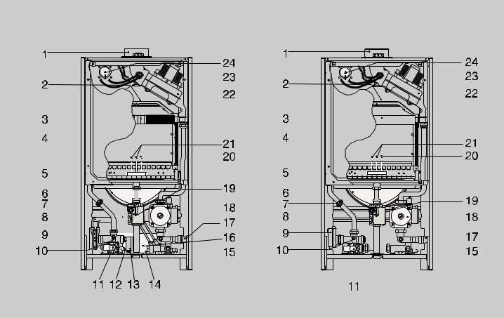
Fig. 1.1
Legend:
1.Flue Connector
2.Combustion Chamber Hood
3.Main Heat Exchanger
4.Combustion Chamber Insulation Panel
5.Burner
6.Expansion Vessel
7.Overheat Thermostat
8.Spark Generator
9. Diverter Valve |
(MFFI) |
Motorised Valve |
(RFFI) |
10.Main Circuit Temperature Probe
11.Main Circuit Flow Switch
12.Domestic Hot Water Temperature Probe
13.Diverter Valve Microswitch
14.Filter Seat
15.Drain Valve
16.Secondary Heat Exchanger
17.Safety Valve (3 bar)
18.Circulation Pump with Automatic Air Release Valve
19.Gas Valve
20.Detection Electrodes
21.Ignition Electrodes
22.Fan
23.Venturi
24.Air Pressure Switch
B004 |
5 |
2. |
INSTALLATION |
The technical information and instructions provided herein below are intended |
||||
|
|
for the installer so that the unit may be installed correctly and safely. |
||||
|
|
The installation and initial startup of the boiler must be by a CORGI Approved |
||||
2.1 |
Reference Standards |
Installer in compliance with the installation standards currently in effect, as well |
||||
as with any and all local health and safety standards i.e. CORGI. |
||||||
|
|
This appliance must be installed by a competent installer in |
||||
|
|
accordance with the current Gas Safety (installation & use) |
||||
|
|
Regulations |
|
|
|
|
|
|
The installation of this appliance must be in accordance with the relevant |
||||
|
|
requirements of the current Gas Safety (installation & use) Regulations, the |
||||
|
|
Local Building Regulations, the current I.E.E. Wiring Regulations, the byelaws |
||||
|
|
of the local water authority, and in Scotland, in accordance with the Building |
||||
|
|
Standards (Scotland) Regulation and Health and Safety document No. 635 |
||||
|
|
“Electricity at work regs. 1989”. |
|
|
|
|
|
|
Installation should also comply with the following British Standard Codes of |
||||
|
|
Practice: |
|
|
|
|
|
|
|
|
|
|
|
|
|
|
|
|
|
|
|
|
|
Low pressure |
|
|
|
|
|
|
pipes |
BS 6891 |
1988 |
|
|
|
|
|
|
|
|
|
|
|
Boilers of rated input |
|
|
|
|
|
|
not exceeding 60 kW |
BS 6798 |
1987 |
|
|
|
|
Forced circulation hot |
|
|
|
|
|
|
water system |
BS 5449 |
1990 |
|
|
|
|
|
|
|
|
|
|
|
Installation of gas hot water |
|
|
|
|
|
|
supplies for domestic purposes |
|
|
|
|
|
|
( 2nd family gases) |
BS 5546 |
1990 |
|
|
|
|
Flues |
BS 5440-1 |
1990 |
|
|
|
|
|
|
|
|
|
|
|
Air supply |
BS 5440-2 |
1989 |
|
|
|
|
|
|
|
|
2.2Siting the Appliance
The appliance may be installed in any room or indoor area, although particular attention is drawn to the requirements of the current I.E.E. Wiring Regulations, and in Scotland, the electrical provisions of the Building Regulations applicable in Scotland, with respect to the installation of the combined appliance in a room containing a bath or shower.
Where a room-sealed appliance is installed in a room containing a bath or shower the boiler and any electrical switch or appliance control, utilising mains electricity should be situated so that it cannot be touched by a person using the bath or shower.
The location must permit adequate space for servicing and air circulation around the appliance as indicated in paragraph 2.4.
The location must permit the provision of an adequate flue and termination. For unusual locations special procedures may be necessary.
BS 6798-1987 gives detailed guidance on this aspect.
A compartment used to enclose the appliance must be designed specifically for this purpose. No specific ventilation requirements are needed for an installation within a cupboard
This appliance is not suitable for outdoor installation.
The type C appliances (in which the combustion circuit, air vent intake and combustion chamber are air-tight with respect to the room in which the appliance is installed) can be installed in any type of room.
There are no limitations with respect to ventilation and the volume of the room itself. The boiler must be installed on a solid, permanent wall to prevent access to the electrical parts (when live) through the aperture on the back frame.
6 |
B004 |

2.3Overall Dimensions
GENUS 23/27/30 MFFI
 385
385
465
Legend:
A = Central Heating Flow (3/4”)
B = Domestic Hot Water Outlet (1/2”) C = Gas Inlet (3/4”)
D = Domestic Cold Water Inlet (1/2”) E = Central Heating Return (3/4”)
F = Cylinder Flow (3/4”) G = Cylinder Return (3/4”)
Fig. 2.1
2.4Clearances
890 |
(A-B-D-E) |
|
|
|
(C) |
GENUS 27 RFFI SYSTEM
|
|
|
30 |
49 |
99 |
99 |
85 |
(F - G) |
|
|
|
|||
|
|
|
||
|
|
155 |
(A - D - E) |
|
132 |
67 |
65 |
(C) |
|
|
|
208 |
|
AF C DGE
In order to allow for access to the interior of the boiler for maintenance purposes, the boiler must be installed in compliance with the clearance requirements indicated in the diagram below.
GENUS 23/27/30 MFFI |
GENUS 27 RFFI SYSTEM |
|||
110 |
|
|
|
|
|
160 |
400 |
|
|
197 |
60 |
60 |
|
|
|
|
|
||
450 |
|
|
|
|
|
|
|
300 |
|
Fig. 2.2
B004 |
7 |
2.5 |
Mounting the Appliance |
Fasten the boiler in place using the template and anchors supplied with the |
|
|
unit. It is highly recommended that a spirit level be used to position the boiler so |
|
|
that it is perfectly level. |
|
|
For additional information, please consult the instructions contained in the |
|
|
connection kit and the flue kit. |
2.6 |
Electrical Connection |
For safety purposes, have a competent person carefully check the electrical |
system in the property, as the manufacturer will not be held liable for damage caused by the failure to earth the appliance properly or by anomalies in the supply of power. Make sure that the residential electrical system is adequate for the maximum power absorbed by the unit, which is indicated on the rating plate. In addition, check that the section of cabling is appropriate for the power absorbed by the boiler.
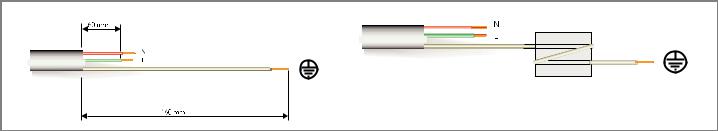
The boiler operates with alternating current, as indicated in the technical data table (1.2), where the maximum absorbed power is also indicated. Make sure that the connections for the neutral and live wires correspond to the indications in the diagram. The appliance electrical connections are situated on the reverse of the control panel (see the servicing manual for further information)
Fig. 2.3 |
Important! |
2.7Gas Connection
In the event that the power supply cord must be changed, replace it with one with the same specifications. Make the connections to the terminal board located within the control panel, as follows:
-The yellow-green wire should be connected to the terminal marked with the earth symbol; make sure to re-use the ferrule mounted on the other supply cord;
-The blue wire should be connected to the terminal marked “N”;
-The brown wire should be connected to the terminal marked “L”.
Note: The diagrams for the electrical system are indicated in section 2.11.
Warning, this appliance must be earthed.
External wiring to the appliance must be carried out by a qualified technician and be in accordance with the current I.E.E. Regulations and applicable local regulations. The Genus range of boilers are supplied for connection to a 230 V~ 50 Hz supply.
The supply must be fused at 3 A.
The method of connection to the electricity supply must facilitate complete electrical isolation of the appliance, by the use of a fused double pole isolator having a contact separation of at least 3 mm in all poles or alternatively, by means of a 3 A fused three pin plug and unswitched shuttered socket outlet both complying with BS 1363.
The point of connection to the Electricity supply must be readily accessible and adjacent to the appliance unless the appliance is installed in a bathroom when this must be sited outside the bathroom.
The local gas supplier contractor connects the gas meter to the service pipe.
If the gas supply for the boiler serves other appliances ensure that an adequate supply is available both to the boiler and the other appliances when they are in use at the same time.
Pipe work must be of an adequate size. Pipes of a smaller size than the boiler inlet connection should not be used.
8 |
B004 |
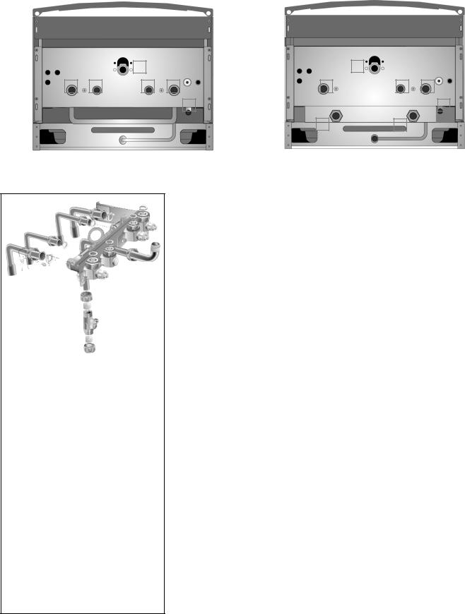
2.8 Water Connections |
|
View of the Boiler Connections |
GENUS 23/27/30 MFFI |
GENUS 27 RFFI SYSTEM |
|
|
|
|
|
|
|
|
|
|
|
|
|
|
|
|
|
|
|
|
|
|
|
|
|
C |
|
|
|
|
|
|
|
|
C |
|
|
|
|
|
|
|
|
|
A |
B |
D |
E |
|
|
|
|
|
|
|
|
|
|
|
|
|
|
|
|
|
|
|
A |
D |
E |
|||||||||||||||
|
|
|
|
|
|
I |
|
|
|
|
|
|
|
|
|
|
|
|
|
|
|
|
|
|
|
|
|
|
|
|
I |
||||||||||
|
|
|
|
|
|
|
|
|
|
|
|
|
|
|
|
|
|
|
|
|
|
|
|
|
|
|
|
|
F |
|
|
|
G |
|
|
|
|
|
|||
|
|
|
|
|
|
|
|
|
|
|
|
|
|
|
|
|
|
|
|
|
Fig. 2.5
Fitting the connection kit to the Genus 27 RFFI System only.
It will be noted that the kit has two connections not required for this boiler i.e. the domestic cold inlet “E” and the domestic hot water outlet “B” (see fig. 2.4).
Although the cold water main supply must be connected to the isolation valve for the purpose of operating the fillingloop, the isolation valve is NOT connected to the boiler and should be left in the OFF position.
The D.H.W. outlet is capped-off on the boiler, therefore not requiring the isolation valve to be used.
The Genus 27 RFFI System has 2 x 3/4" B.S.P. male threads for the cylinder flow and return. It is recommended that 2 x 22mm x 3/4" female iron fittings (not supplied) be used on these connections (using P.T.F.E. tape), before the boiler is mounted on the wall.
Legend |
Fig. 2.4 |
A = Central Heating Flow
B = Domestic Hot Water Outlet
C = Gas Inlet
D = Domestic Cold Water Inlet
E = Central Heating Return
F = Cylinder Flow
G = Cylinder Return
I = Safety Valve
Central Heating
Detailed recommendations are given in BS 6798:1987 and BS 5449-1:1990, the following notes are given for general guidance.
Pipe Work:
Copper tubing to BS EN 1057:1996 is recommended for water pipes. Jointing should be either with capillary soldered or compression fittings.
Where possible pipes should have a gradient to ensure air is carried naturally to air release points and water flows naturally to drain taps.
The appliance has a built-in automatic air release valve, however it should be ensured as far as possible that the appliance heat exchanger is not a natural collecting point for air.
Except where providing useful heat, pipes should be insulated to prevent heat loss and avoid freezing.
Particular attention should be paid to pipes passing through ventilated spaces in roofs and under floors.
By-pass:
The appliance includes an automatic by-pass valve, which protects the main heat exchanger in case of reduced or interrupted water circulation through the heating system, due to the closing of thermostatic valves or cock-type valves within the system.
System Design:
This boiler is suitable only for sealed systems.
Drain Cocks:
These must be located in accessible positions to permit the draining of the whole system. The taps must be at least 15mm nominal size and manufactured in accordance with BS 2870:1980.
Safety Valve Discharge:
The discharge should terminate facing downwards on the exterior of the building in a position where discharging (possibly boiling water & steam) will not create danger or nuisance, but in an easily visible position, and not cause damage to electrical components and wiring.
The discharge must not be over an entrance or a window or any other type of public access.
B004 |
9 |
2.9Flue Connections
Air Release Points:
These must be fitted at all high points where air naturally collects and must be sited to facilitate complete filling of the system.
The appliance has an integral sealed expansion vessel to accommodate the increase of water value when the system is heated.
It can accept up to 7 l (1.5 gal) of expansion water. If the heating circuit has an unusually high water content, calculate the total expansion and add an additional sealed expansion vessel with adequate capacity.
Mains Water Feed - Central Heating:
There must be no direct connection to the mains water supply even through a non-return valve, without the approval of the Local Water Authority.
Filling:
A temporary method for initially filling the system and replacing lost water during servicing and initial filling (in accordance with Water Supply Byelaw 14), is provided as an intergal part of the connection kit (see fig. 2.5). The flexible hose must be removed once the system has been filled. The D.H.W. inlet valve on the connection kit has two postions, one for winter and one for the summer. This enables the flow-rate through the appliance to be adjusted so that a sensible D.H.W. temperature may be achieved throughout the year.
Domestic Water
The domestic water must be in accordance with the relevant recommendation of BS 5546:1990. Copper tubing to BS EN 1057:1996 is recommended for water carrying pipe work and must be used for pipe work carrying drinking water.
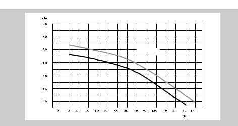
Residual Head of the Boiler
27/30 kW
23 kW
Flue System
The provision for satisfactory flue termination must be made as described in BS 5440-1.
The appliance must be installed so that the flue terminal is exposed to outdoor air. The terminal must not discharge into another room or space such as an outhouse or lean-to.
It is important that the position of the terminal allows a free passage of air across it at all times.
The terminal should be located with due regard for the damage or discolouration that might occur on buildings in the vicinity.
In cold or humid weather water vapour may condense on leaving the flue terminal.
The effect of such “steaming” must be considered.
If the terminal is less than 2 metres above a balcony, above ground or above a flat roof to which people have access, then a suitable terminal guard must be fitted. When ordering a terminal guard, quote the appliance model number.
10 |
B004 |
Loading...