

Page 1

User Guide
AirTight Management Console
Version 7.1 Update 5
Page 2

This page is intentionally left blank
Page 3

END USER LICENSE AGREEMENT
Please read the End User License Agreement before installing AirTight Management Console/AirTight
Wi-Fi/AirTight WIPS. The End User License Agreement is available at the following location
http://www.airtightnetworks.com/fileadmin/pdf/AirTight-EULA.pdf
.
Installing AirTight Manage ment Console/AirTight Wi-Fi/AirTight WIPS constitutes your acceptance of the
terms and conditions of the End User License Agreement.
DISCLAIMER
THE INFORMATION IN THIS GUIDE IS SUBJECT TO CHANGE WITHOUT ANY PRIOR NOTICE.
AIRTIGHT
®
NETWORKS, INC. IS NOT LIABLE FOR ANY SPECIAL, INCIDENTAL, INDIRECT, OR
CONSEQUENTIAL DAMAGES WHATSOEVER (INCLUDING, WITHOUT LIMITATION, DAMAGES FOR
LOSS OF BUSINESS PROFITS, BUSINESS INTERRUPTION, LOSS OF BUSINESS INFORMATION,
OR ANY OTHER PECUNIARY LOSS) ARISING OUT OF THE USE OF OR INABILITY TO USE THIS
PRODUCT.
THIS PRODUCT HAS THE CAPABILITY TO BLOCK WIRELESS TRANSMISSIONS FOR THE
PURPOSE OF PROTECTING YOUR NETWORK FROM MALICIOUS WIRELESS ACTIVIT Y. BASE D
ON THE POLICY SETTINGS, YOU HAVE THE ABILITY TO SELECT WHICH WIRELESS
TRANSMISSIONS ARE BLOCKED AND, THEREFORE, THE CAPABILITY TO BLOCK AN EXT ERNAL
WIRELESS TRANSMISSION. IF IMPROPERLY USED, YOUR USAGE OF THIS PRODUCT MAY
VIOLATE US FCC PART 15 AND OTHER LAWS. BUYER ACKNOWLEDGES THE LEGAL
RESTRICTIONS ON USAGE AND UNDERSTANDS AND WILL COMPLY WITH US FCC
RESTRICTIONS AS WELL AS OTHER GOVERNMENT REGULATIONS. AIRTIGHT IS NOT
RESPONSIBLE FOR ANY WIRELESS INTERFERENCE CAUSED BY YOUR USE OF THE PRODUCT.
AIRTIGHT NETWORKS, INC. AND ITS AUTHORIZED RESELLERS OR DI ST RIBUTORS WILL
ASSUME NO LIABILITY FOR ANY DAMAGE OR VIOLATION OF GOVERNMENT REGULATIONS
ARISING FROM YOUR USAGE OF THE PRODUCT, EXCEPT AS EXPRESSLY DEFINED IN THE
INDEMNITY SECTION OF THIS DOCUMENT.
LIMITATION OF LIABILITY
AirTight Networks will not be liable to customer or any other party for any indirect, incidental, special,
consequential, exemplary, or reliance damages arising out of or related to the use of AirTight Wi-Fi,
AirTight WIPS, AirTight Cloud Services, and AirTight devices under any legal theory, including but not
limited to lost profits, lost data, or business interruption, even if AirTight Networks knows of or should
have known of the possibility of such damages. Regardless of the cause of action or the form of action,
the total cumulative liability of AirTight Networks for actual damages arising out of or related to the use of
AirTight Wi-Fi, AirTight WIPS, AirTight Cloud Services or AirTight devices will not exceed the respective
price paid for AirTight Wi-Fi, AirTight WIPS, AirTight Cloud Services, or AirTight devices.
Copyright © 2013-20 15 Air Tight
Powered by Marker Packet
Forensics
TM
, WEPGuardTM and WPAGuardTM. AirTight Networks and the AirTight Networks logo are
®
Networks, Inc. All Rights Reserved.
TM
, Active ClassificationTM, Live EventsTM, VLAN Policy M appingTM, Smart
trademarks and AirTight is a registered trademark of AirTight Networks, Inc.
This product contains components from Open Source software. These components are governed by the
terms and conditions of the GNU Public License. To read these terms and conditions visit
http://www.gnu.org/copyleft/gpl.html
.
Protected by one or more of U.S. patent Nos. 7,002,943; 7,154,874; 7,216,365; 7,333,800; 7,333,481;
7,339,914; 7,406,320; 7,440,434; 7,447,184; 7,496,094; 7,536,723; 7,558,253; 7,710,933; 7,751,393;
7,764,648; 7,804,808; 7,856,209; 7,856,656; 7,970,894; 7,971,253; 8,032,939; and international patents:
AU 200429804; GB 2410154; JP 4639195; DE 60 2004 038 621.9; and GB/NL/FR/SE 1976227. More
patents pending. For more information on patents, please visit:
www.airtightnetworks.com/patents
Page 4

Table of Contents
About This Guide .......................................................................................................................................... 1
Intended Audience ..................................................................................................................................... 1
Product and Documentation Updates ....................................................................................................... 1
Contact Information ................................................................................................................................... 1
Introduction.................................................................................................................................................... 3
AirTight Management Console Conf ig ur ati on ............................................................................................... 7
Configure Language Setting ...................................................................................................................... 7
Set System Language............................................................................................................................ 7
Set SSID encoding ................................................................................................................................. 7
Copy Language Setting to Another Server ............................................................................................ 8
Configure Time Zone and Tag for Location ............................................................................................... 8
Set Time Zone ....................................................................................................................................... 8
Edit Time Zone ....................................................................................................................................... 8
Set Location Tag ................................................................................................................................... 9
User Management ..................................................................................................................................... 9
Configure Password Policy .................................................................................................................. 12
Configure Account Suspension Setting ............................................................................................... 13
Configure Login Parameters ................................................................................................................ 14
User Authentication ................................................................................................................................. 16
Configure LDAP Server Parameters .................................................................................................... 16
Configure RADIUS Parameters ........................................................................................................... 18
Configure Parameters for Certificate-based authentication................................................................. 20
Wireless Intrusion Prevention System ..................................................................................................... 22
Manage Authorized WLAN Policy ........................................................................................................ 23
Configure AP Auto-classification Policy ............................................................................................... 25
Configure Client Auto-classification Policy .......................................................................................... 26
Intrusion Prevention ............................................................................................................................. 30
Activate Intrusion Prevention for Location ........................................................................................... 32
Import Device List ................................................................................................................................ 33
Manage Banned Device List ................................................................................................................ 35
Manage Hotspot SSIDs ....................................................................................................................... 36
Manage Vulnerable SSIDs .................................................................................................................. 38
Manage Smart Device Types .............................................................................................................. 39
Manage WiFi Access ............................................................................................................................... 41
Manage SSID Profiles.......................................................................................................................... 41
Manage Mesh Profiles ......................................................................................................................... 82
Configure Event Notification ................................................................................................................ 87
i
Page 5

AirTight Management Console User Guide
Activate Event Generation for Location ............................................................................................... 88
Configure Email Recipients ................................................................................................................. 89
Configure Device - Server Communication Settin gs ............................................................................... 89
Use Key for Device - Server Communication ...................................................................................... 89
Use Passphrase for Device - Server Communication ......................................................................... 89
Reset Communication Key .................................................................................................................. 89
Manage Policy Templates ....................................................................................................................... 90
Add Policy Template ............................................................................................................................ 90
Edit Policy Template ............................................................................................................................ 91
Search Policy Template ....................................................................................................................... 92
Copy Policy Template to Another Location ......................................................................................... 93
Save Policy Template with a Different Name ...................................................................................... 93
Print Policy Template List .................................................................................................................... 93
Delete Policy Template ........................................................................................................................ 93
Manage Authorized WLAN Policy ........................................................................................................... 94
Configure Authorized WLAN Policy ..................................................................................................... 95
Edit Authorized WLAN Policy .............................................................................................................. 95
View High Availability Status for Server .................................................................................................. 96
View/Upgrade License Details ................................................................................................................ 97
Manage Look and Feel of Reports .......................................................................................................... 98
Customize Report Header Text ........................................................................................................... 98
Customize Summary Table ................................................................................................................. 98
Customize Section Results .................................................................................................................. 99
Restore Default Look and Feel Settings .............................................................................................. 99
Copy Reports Look and Feel Settings to Another Server .................................................................... 99
Configure NTP ....................................................................................................................................... 100
Check Time Drift between AirTight server and NTP server............................................................... 100
Synchronize AirTight Server Time with NTP Server .......................................................................... 100
Disable NTP ....................................................................................................................................... 100
Configure RF Propagation Settings ....................................................................................................... 100
Restore RF Propagation Defaults ...................................................................................................... 102
Copy RF Propagation Setting to Another Server ............................................................................... 102
Configure Live RF View Setting ............................................................................................................ 103
Restore Default Live RF View Settings.............................................................................................. 103
Copy Live RF View Setting to Another Server ................................................................................... 103
Configure Location Tracking.................................................................................................................. 104
Restore Location Tracking Configuration Defaults ............................................................................ 104
Copy Location Tracking Configuration to Another Server ................................................................. 104
Manage Auto Location Tagging ............................................................................................................ 105
ii
Page 6

Table of Contents
Restore Auto Location Tagging Defaults ........................................................................................... 105
Copy Auto Location Tagging Settings to Another Server .................................................................. 106
Set up and Manage Server Cluster ....................................................................................................... 107
Benefits of Server Cluster .................................................................................................................. 107
Create and Manage Server Cluster ................................................................................................... 108
Manage Child Servers from Parent Server in Server Cluster ............................................................ 115
Manage Vendor OUIs ............................................................................................................................ 119
Add Vendor or MAC Prefix ................................................................................................................ 119
Delete Vendor or MAC Prefix ............................................................................................................ 119
Manage Device Template...................................................................................................................... 119
Customize Policy/Device Template for Location ............................................................................... 121
Revert to Inherited Device Template ................................................................................................. 121
Add Device Template......................................................................................................................... 122
Edit Device Template ......................................................................................................................... 128
Search Device Template ................................................................................................................... 128
Copy Device Template....................................................................................................................... 128
Print Device Template List for Location ............................................................................................. 129
Delete Device Template..................................................................................................................... 129
Configure SMTP Settings ...................................................................................................................... 129
Restore SMTP Configuration Defaults ............................................................................................... 130
Test SMTP Settings ........................................................................................................................... 131
Copy SMTP Configuration to Another Server .................................................................................... 131
View System Status ............................................................................................................................... 131
Start/Stop Server ............................................................................................................................... 132
Upgrade Server ..................................................................................................................................... 132
Configure Auto Deletion Settings .......................................................................................................... 133
Copy Auto Deletion Settings to Another Server ................................................................................ 134
Manage Audit Log Settings ................................................................................................................... 135
Set Duration for Audit Log Download ................................................................................................ 135
Download Audit Logs ......................................................................................................................... 135
Restore Default User Action Log Download Settings ........................................................................ 135
Copy Audit Log Settings to Another Server ....................................................................................... 136
Configure Integration with Enterprise Security Management Servers .................................................. 137
Syslog Integration .............................................................................................................................. 137
Arcsight Integration ............................................................................................................................ 138
SNMP Integration ............................................................................................................................... 140
Manage WLAN Integration .................................................................................................................... 142
WLAN Integration ............................................................................................................................... 142
Manage Integration with Aruba Mobility Controllers .......................................................................... 142
iii
Page 7

AirTight Management Console User Guide
Configure Integration with HP MSM Controller .................................................................................. 145
Manage Integration with Cisco WLC ................................................................................................. 148
Manage Integration with Meru ........................................................................................................... 151
Manage AirTight Mobile Clients ............................................................................................................ 152
AirTight Mobile Settings ..................................................................................................................... 152
Manage AirTight Mobile Clients ......................................................................................................... 153
Add AirTight Mobile Group Manually ................................................................................................. 157
Edit AirTight Mobile Group ................................................................................................................. 157
Attach Policy to AirTight Mobile Group .............................................................................................. 158
Overwrite Existing Policy for AirTight Mobile Group .......................................................................... 158
Detach Policy from AirTight Mobile Group......................................................................................... 158
View AirTight Mobile Group Policy in HTML Format ......................................................................... 158
View AirTight Mobile Group Policy in XML Format ............................................................................ 159
Activate Automatic Client Grouping ................................................................................................... 159
Apply Default Policy to New Groups .................................................................................................. 159
Print List of AirTight Mobile Groups for Location ............................................................................... 159
Delete AirTight Mobile Group ............................................................................................................ 160
Dashboard ................................................................................................................................................. 161
Add a page to dashboard ...................................................................................................................... 161
Delete a page from dashboard .............................................................................................................. 162
Print dashboard page ............................................................................................................................ 162
WIPS Widgets ....................................................................................................................................... 162
Network Widgets ................................................................................................................................... 163
Client Widgets ....................................................................................................................................... 165
Access Point Widgets ............................................................................................................................ 165
Devices ...................................................................................................................................................... 167
AirTight Devices .................................................................................................................................... 167
Device Properties ............................................................................................................................... 168
View Visible LANs .............................................................................................................................. 173
View Visible APs ................................................................................................................................ 173
View Visible Clients ............................................................................................................................ 173
View Active APs ................................................................................................................................. 173
View Active Clients ............................................................................................................................ 173
View AirTight Device Events .............................................................................................................. 173
View Channel Occupancy .................................................................................................................. 173
View Interference ............................................................................................................................... 174
View Mesh Network Links .................................................................................................................. 174
Search AirTight Devices .................................................................................................................... 174
Sort AirTight Devices ......................................................................................................................... 174
iv
Page 8

Table of Contents
Change Location ................................................................................................................................ 174
Print AirTight Device Information for Location ................................................................................... 174
Reboot Device ................................................................................................................................... 175
Troubleshoot Device .......................................................................................................................... 175
Upgrade or Repair Device ................................................................................................................. 178
Enable Pagination for AirTight Device Listing and Set Page Size .................................................... 178
Disable Pagination for AirTight Device Listing ................................................................................... 180
Add Custom Filter .............................................................................................................................. 180
Edit Custom Filter .............................................................................................................................. 180
Delete Custom Filter .......................................................................................................................... 181
Delete Device ..................................................................................................................................... 181
Monitor Clients ....................................................................................................................................... 181
View Client Properties........................................................................................................................ 183
View Recently Associated APs/Ad hoc networks .............................................................................. 185
View Events related to Client ............................................................................................................. 185
View Client Retransmission Rate Trend ............................................................................................ 185
View Devices Seeing Client ............................................................................................................... 185
View Client Average Data Rate ......................................................................................................... 186
View Client Traffic .............................................................................................................................. 186
Change Client Location...................................................................................................................... 186
Quarantine Client ............................................................................................................................... 186
Disable Auto Quarantine/Exclude Device from Intrusion Prevention Policy ...................................... 186
Add to banned list .............................................................................................................................. 187
Classify / Declassify as Smart Device ............................................................................................... 187
Change Client Category..................................................................................................................... 187
Reset Data Transmitted by Client ...................................................................................................... 187
Locate Client ...................................................................................................................................... 187
View Recently Probed SSIDs ............................................................................................................ 187
Troubleshoot Client ............................................................................................................................ 188
Debug Client Connection Problems ................................................................................................... 191
Download Connection Log ................................................................................................................. 192
Delete Connection Log History .......................................................................................................... 193
Enable Pagination for Client Listing and Set Page Size .................................................................... 194
Disable Pagination for Client Listing .................................................................................................. 194
Add Custom Filter .............................................................................................................................. 194
Edit Custom Filter .............................................................................................................................. 195
Delete Custom Filter .......................................................................................................................... 195
Print Client List for Location ............................................................................................................... 195
Delete Client ...................................................................................................................................... 196
v
Page 9

AirTight Management Console User Guide
Spectrogram .......................................................................................................................................... 196
Monitor Access Points (APs) ................................................................................................................. 196
View AP Properties ............................................................................................................................ 198
View Recently Associated Cli ents ..................................................................................................... 201
View AP Utilization ............................................................................................................................. 201
View AP Associated Clients ............................................................................................................... 202
View AP Traffic .................................................................................................................................. 202
View AP Average Data Rate .............................................................................................................. 202
View Devices Seeing AP ................................................................................................................... 202
View AP Events ................................................................................................................................. 202
Change AP Location .......................................................................................................................... 202
Locate AP .......................................................................................................................................... 203
Quarantine an AP .............................................................................................................................. 203
Change AP Category ......................................................................................................................... 203
Disable Auto Quarantine .................................................................................................................... 203
Add to banned list .............................................................................................................................. 203
Sort APs ............................................................................................................................................. 203
Filter AP Details ................................................................................................................................. 204
Search APs ........................................................................................................................................ 204
Enable Pagination for AP Listing and Set Page Size ........................................................................ 204
Disable Pagination for AP Listing ...................................................................................................... 205
Add Custom Filter .............................................................................................................................. 205
Edit Custom Filter .............................................................................................................................. 205
Delete Custom Filter .......................................................................................................................... 206
Print AP List for Location ................................................................................................................... 206
Merge APs ......................................................................................................................................... 206
Split AP .............................................................................................................................................. 207
Troubleshoot AP ................................................................................................................................ 207
Delete AP ........................................................................................................................................... 210
Monitor Networks ................................................................................................................................... 211
Manage Locations and Locatio n La yout ................................................................................................... 215
Define Location Tree ............................................................................................................................. 215
Add Location .......................................................................................................................................... 217
Edit Location .......................................................................................................................................... 217
Move Location ....................................................................................................................................... 218
Delete Location ...................................................................................................................................... 218
Search Locations ................................................................................................................................... 218
Add Layout ............................................................................................................................................ 218
Edit Layout ............................................................................................................................................. 219
vi
Page 10

Table of Contents
Delete Layout ........................................................................................................................................ 220
Show / Hide Location List ...................................................................................................................... 220
Show/Hide Devices on Location Layout ................................................................................................ 220
Place Devices/Locations on Location Layout ........................................................................................ 220
Remove Devices/Locations from Location Layout ................................................................................ 221
View RF Coverage / Heat Maps ............................................................................................................ 221
View AP Coverage ............................................................................................................................. 222
View AP Coverage by RSSI Value .................................................................................................... 222
View Sensor Coverage ...................................................................................................................... 222
View AP Link Speed .......................................................................................................................... 223
View AP Channel Coverage .............................................................................................................. 223
Calibrate RF Views ................................................................................................................................ 223
Zoom in / Zoom out Layout.................................................................................................................... 224
Adjust the Layout Opacity...................................................................................................................... 224
Add Note ................................................................................................................................................ 224
Edit Note ................................................................................................................................................ 225
Move Note ............................................................................................................................................. 225
Hide Notes ............................................................................................................................................. 225
Show Notes ........................................................................................................................................... 225
View Mesh Topology ............................................................................................................................. 226
Hide Mesh Topology .............................................................................................................................. 226
View and Manage Events ......................................................................................................................... 227
View Events for Location ....................................................................................................................... 228
View Deleted Events for Location ......................................................................................................... 228
Change Event Location ......................................................................................................................... 228
Acknowledge Event ............................................................................................................................... 229
Turn on Vulnerability Status for Event ................................................................................................... 229
Turn off Vulnerability Status for Event ................................................................................................... 229
Mark Event as Read .............................................................................................................................. 229
Mark Event for Deletion ......................................................................................................................... 229
Enable Pagination for Event Listing and Set Page Size ....................................................................... 230
Disable Pagination for Event Listing ...................................................................................................... 230
Add Custom Filter .................................................................................................................................. 230
Edit Custom Filter .................................................................................................................................. 231
Delete Custom Filter .............................................................................................................................. 231
Print Event List for Location................................................................................................................... 231
Forensics ................................................................................................................................................... 233
View AP based /Client based Threat Details......................................................................................... 233
View Event Summary......................................................................................................................... 234
vii
Page 11

AirTight Management Console User Guide
View Participating Devices and Quarantine Status ........................................................................... 234
Locate Participating Device ............................................................................................................... 235
View Administration Action Logs for Event ........................................................................................ 236
Acknowledge Event ........................................................................................................................... 236
Change Location of the Event ........................................................................................................... 236
Turn Vulnerability On/Off ................................................................................................................... 237
Print Event List for Location ............................................................................................................... 237
Mark Event for Deletion ..................................................................................................................... 237
Mark Event as Read .......................................................................................................................... 237
Show/Hide Deleted Events ................................................................................................................ 238
Reports ...................................................................................................................................................... 239
Analytics ................................................................................................................................................ 248
Manage Report Archive ......................................................................................................................... 250
Fetch Archived Report ....................................................................................................................... 251
Rename Archived Report .................................................................................................................. 251
Print Archived Report List for Location .............................................................................................. 251
Delete Archived Report ...................................................................................................................... 251
Schedule Report Generation ................................................................................................................. 251
Send report by e-mail......................................................................................................................... 255
Archive report ..................................................................................................................................... 255
View Report Schedules ......................................................................................................................... 255
Glossary of Icons ...................................................................................................................................... 257
viii
Page 12

Important! Please read the EULA before installing AirTight WIPS or AirTight Wi-Fi. Installing AirTight
WIPS or AirTight Wi
above in this document.
About This Guide
The AirTight Management Console User Guide explains how to configure and manage the AirTight
Management Console .
-Fi constitutes your acceptance of the terms and conditions of the EULA mentioned
Intended Audience
This guide is intended for anyone who wants to configure and use AirTight WIPS or AirTight Wi-Fi or use
AirTight Cloud Services.
Product and Documentation Updates
To receive important news on product updates, please visit our website at
http://www.airtightnetworks.com
We continuously enhance our product documentation based on customer feedback. To obtain a latest
copy of this document, visit http://www.airtightnetworks.com/home/support.html
.
.
Contact Information
AirTight® Networks, Inc.
339 N, Bernardo Avenue, Suite #200,
Mountain View, CA 94043
Tel: (650) 961-1111
Fax: (650) 963-3388
For technical support, send an email to [email protected]
1
Page 13

Page 14

•
Introduction
AirTight Management Console is a HTML 5 based user interface using which you can configure and
monitor AirTight WIPS and/or AirTight Wi-Fi server to access the AirTight Cloud Services.
HTML 5 makes AirTight Management Console compatible with most browsers and operating systems.
AirTight Management Console is intuitive and easy to use. It can be configured with ease to suit your
WIPS and/or Wi-Fi needs.
The Console is divided into 7 sections - Dashboard, Locations, De vices , Ev ents, For ensic s,
Configuration, and Reports.
AirTight Management Console can be configured from the Configuration section. You can define and
manage users, configure and manage WIPS settings, Wi-Fi access settings, integration settings for
WLAN, integration settings for enterprise security management servers etc from the configuration section.
The Dashboard section provides a graphical view of the WIPS and/or Wi-Fi implementation. It offers you
the flexibility to choose from a good number of graphs related to the access points, clients on your
wireless network, as well as the networks detected by WIPS sensors. Details of wireless threats to the
network can be seen on the WIPS widgets.
Apart from the pie chart or bar graph representation, the widget data can be viewed as a tabular
representation by clicking the icon present on the top of widgets. You can alternate between tabular
view and pie chart/bar graph view. This means that if you are in the pie/graph view, you will see the
icon. If you are in the table view, you will see the or icon, depending on whether the alternate
view is represented as a pie chart or bar graph.
The widget data is presented in the last-v ie wed for mat when you log in to AirTight Management Consol e
the next time.
AirTight Management Console facilitates the creation of locations. These locations could be various
buildings in your campus or the different floors or levels in your office space. You can create and manage
your retail or office locations using the Locations section. You can attach a layout to each floor in the
office space. You can then define WIPS / Wi-Fi policies specific to these locations.
All APs, AirTight devices, sensors, smart devices are seen under the Devices section. Apart from the
actual devices, the devices sect ion also disp lays a list of networks detected by the WIPS sensors.
The Events section displays the events detected by the WIPS implementation.
The Forensics section lists AP-based threats and client-based threats in a user friendly format. You can
drill down into the wireless threats using the forensics section.
The Reports section facilitates generation of various built-in and custom reports. These reports comprise
various compliance reports and reports related to devices in the network and events occurring in the
network. You can schedule reports and generate analytics data using the Reports section.
Following are the salient features of the AirTight Management Console.
Intuitive, portabl e and easy-to-use HTML5 UI
3
Page 15

AirTight Management Console User Guide
•
•
HTML5 makes AirTight Management Console compatible with most browsers and operating
systems. It can be operated using tablets and other smart devices as well. The interface is intuitive
and can be used and configured without much effort.
Fully user-customizable dashboards and screens
The dashboard offers you the flexibility to choose from a good number of graphs displaying access
point, client, network, and WIPS statistics.
Graphs are seen in widgets. You can have multiple dashboards on the console. Each dashboard
can have multiple widgets based on your requirement, with widget repetition allowed.
The widget classification is very intuitive. The widgets are classified as network widgets, access
point widgets, client widgets and WIPS widgets.
In all other sections of the UI, you can filter the information or columns visible in the respective
section, based on your requirement.
You also have the option to view information in various text and graphical format in some of the
sections. For example, the Forensics section displays information in text and pie chart formats. In
the Reports section, you can customize the reports as required. Standard compliance reports are
also available.
You can customize filters on device and event listings under Devices and Events respectively.
You can add, edit and delete custom filters on device and event listings. You can define multiple
filters on devices and events listings and save them. These will be retained until you delete them.
When you apply a filter to device or event listing during a login session, the filtered list is retained
till the end of the session.
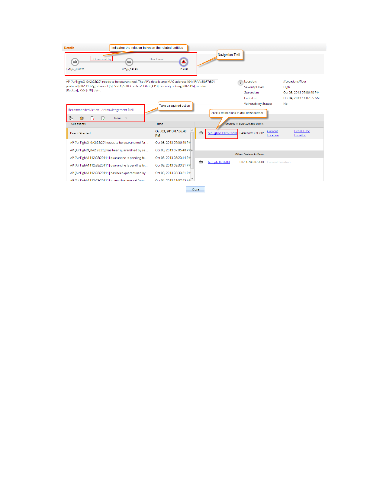
Innovative drill down with navigation trail on any event, chart or device
AirTight Management Console provides a unique feature with which you can delve deeper or drill
down to events or devices from any section of the console where they are visible. The devices and
events are seen as links across AirTight Management Console. You can click on the link to view
the details of the respective event or device and the related devices or events. You can also take
the required actions if you have the privilege to take those actions. Thus, you can hop across
different sections by clicking the links for devices and events. When you navigate across pages in
this way, a navigation trail is displayed at the top of the currently viewed page or screen. This is
extremely useful for you to understand the path you have taken to drill down to the desired page.
The navigation trail also makes it convenient for you to navigate back to one of the screens or
pages in the navigation trail.
See the image below for a sample drill down with a navigation trail.
4
Page 16
Introduction
•
•
•
•
Rich Visualization of Heat maps
You can view radio frequency heat maps in various views. The AP coverage view is useful to find
out the available signal strength at each point. The sensor coverage view enables you to view the
detection and prevention zones of visibility for selected sensors. The color-coding scheme used
enhances the readability of the heat maps.
Hierarchical management architecture ideal for geographically dis trib u ted sites
AirTight Management Console provides for hierarchical management of geographically distributed
sites. You can create a hierarchy of locations or a location tree. Each location folder could
represent a country and a child location folder could represent a state. These location folders could
then have city locations as child location folders. One of more buildings in the city office campus
can be represented as child location folders under the respective city location folders. Individual
floors or levels in the office space can be represented by location floors under the location folders
that represent buildings.
You can then define Wi-Fi/WIPS policies specific to each location. You can apply a common policy
to the location folders. These policies are automatically inherited by the child locations. This makes
management of related locations easy and convenient at the click of a button.
Role-based administration and extensible configuration framework
The administration and operation of the Wi-Fi or WIPS solution through AirTight Management
Console is role-based. A user has restricted access to one or more locations that he is associated
with. He is able to view information and configure the console related to these locations only.
Information from other locations are not visible to him. A user is able to perform operations based
on his role. AirTight Management Console provides four distinct user roles-superuser,
administrator, operator and viewer.
Configuration Wizard
When a user logs in to AirTight Management Console, and navigates to Dashboard or Events for
the first time, a configuration wizard guides the user on how to use these functionalities. The
wizard is functional only during the first time view.
5
Page 17

Page 18

AirTight Management Console Configuration
AirTight Management Console needs to be configured appropriately for use, before it can start monitoring
and/or protecting the network. Click Configuration to view the various options to configure in AirTight
Management Console.
The Configuration page displays various categories - Device Configuration, WIPS, User Accounts,
Events and System Settings, AirTight Mobile, ESM Integration.
Device Configuration: Configure and manage the SSID profiles using Device Configuration>SSID
Profiles. The SSID profiles can then be attached to the device templates.
Configure and manage the device templates using Device Configuration>Device Template. These
device templates can then be applied to various devices.
WIPS: Configure and manage the wireless intrusion prevention parameters using WIPS.
User Accounts: User management, password management, LDAP, RADIUS configuration, certificate
configuration, account suspension management is done using User Accounts.
Events: Configure and manage event related settings, e-mail notification on occurrence of certain critical
events using Events.
System Settings: Configure and manage AirTight server-related settings using S yst em Settings.
AirTight Mobile: Configure AirTight Mobile inte gration settings using AirTight Mobile.
ESM Integration: Configure settings for integration with Enterprise Security Management software using
ESM Integration. AirTight Management Console integrates with SNMP, Syslog and Arcsight.
Configure Language Setting
Define the system language and the SSID encoding using the Configuration>Language Setting option.
This setting is used to set the language for email communication, Syslog messages etc.
You can copy language setting from one server to another when the servers are part of the same server
cluster.
Set System Language
The system language is the default language that the system will use to communicate via emails, syslog
messages etc. If you want to use a language other than English as the system language for AirTight
Management Console, the language of your choice should be defined under Language Setting. The
default value for System Language Preference is English.
Set SSID encoding
Parameters like SSID, when configured on the AP using page encoding (either non-English native
window or using a language pack), appear garbled if the page encoding does not match the encoding
selected here.
7
Page 19

AirTight Management Console User Guide
Select the appropriate SSID encoding commonly used in your region, in order to correctly see the local
language SSIDs in the system.
The default value for SSID encoding is UTF-8. To select a different SSID encoding, do the following.
Go to Configuration>System Settings>Language Setting.
1.
Under SSID Encoding, select the required SSID encoding.
2.
Click Save to save the new SSID encoding.
3.
Copy Language Setting to Another Server
You can copy the language setting from one server to another server when both servers are part of the
same server cluster. You can copy language setting from child server to child server, parent server to
child server, or child server to parent server. You must be a superuser or an administrator to copy policies
from one server to another.
To copy language settings, do the following.
Go to Configuration>System Settings>Language Setting on the parent server.
1.
Click Copy Policy. The Copy Policies dia log box appears.
2.
Select the server from which language setting is to be copied.
3.
Select the server to which the ;language setting is to be copied.
4.
Click OK to copy the language setting,
5.
Configure Time Zone and Tag for Location
Set the appropriate time zone for the selected location using the Configuration>System
Settings>Location Specific Attributes page. The time zone settings are specific to individual locations
and cannot be inherited from the parent location. You need administrator privileges to configure the
location time zone for a location.
The time zone settings help in accurate analytics. Make sure to select the correct time zone for the
selected location.
Note that you cannot set a time zone for a location floor because a location floor represents a floor
location in the organization premises. The time zone set for the immediate parent location folder of a
location floor applies to the location floor.
In case you do not set the time zone for a location folder, the analytics data will show the server time
zone in the fields where local time zone is shown.
Set Time Zone
To set the time zone for a location, do the following.
Go to Configuration>System Settings>Location Specific Attributes.
1.
Select the location for which you want to set the time zone.
2.
Select the time zone.
3.
Click Save to save the new time zone. Alternatively, if you want to cancel the operation, click Cancel.
4.
Edit Time Zone
To edit the time zone for a location, do the following.
Go to Configuration>System Settings>Location Specific Attributes.
1.
Select the location for which you want to edit the time zone.
2.
Select the new time zone.
3.
8
Page 20

AirTight Management Console Conf ig ur ati on
Operations
User Roles
Superuser
Administrator
Operator
Viewer
User account management
Set or modify identification and
Yes
No
No
No
Add and delete users
Yes
No
No
No
View and modify properties of any
user (User Management screens)
Yes
No
No
No
Define password strength, account loc kin g
users
Yes
No
No
No
View and modify User Preferences (email,
password, session timeout)
Yes (self
only)
Yes (self
only)
Yes (self
only)
Yes (self
only)
User actions audit
Download user actions audit log
Yes
No
No
No
Modify user actions audit lifetime
Yes
No
No
No
System settings and operating policies
Modify system settings and operating
configuration)
Yes
Yes
No
No
Events, devices and locations
View generated events
Yes
Yes
Yes
Yes
Modify and delete generated events
Yes
Yes
Yes
No
Click Save to save the new time zone. The changed time zone is applied recursively to all the child
4.
location folders.
Set Location Tag
A location tag is the location identifier that could be appended to the circuit ID when DHCP Option 82 is
enabled for an SSID profile configured for this location.
If '%l 'is used in the circuit ID, the AP replaces it with the location tag.
To set the location tag for a location, do the following.
Go to Configuration>System Settings>Location Specific Attributes.
1.
Select the location for which you want to set the location tag.
2.
Enter the location tag.
3.
Click Save to save the changes.
4.
User Management
There are four types of users in AirTight Wi-Fi/AirTight WIPS. They are Superuser, Administrator,
Operator and Viewer.
You can manage user-related operations through Configuration>User Accounts>Users. You can add,
edit, and delete users. You can search users, and print a list of users defined at a location.
You need administrator privileges to manage users in AirTight Management Console.
The following table details the role-wise rights in AirTight Management Console.
authentication option (Password only,
Certificate only, Certificate and Password,
Certificate or Password)
policy, maximum concurrent sessions for all
policies (all settings under Configuration tab
other than User Management, Logs, Login
9
Page 21

AirTight Management Console User Guide
View devices
Yes
Yes
Yes
Yes
Add, delete, and modify devices (APs,
Clients, Sensors)
Yes
Yes
Yes
No
View locations
Yes
Yes
Yes
Yes
Add, delete, and modify locations
Yes
Yes
Yes
No
Calibrate location tracking
Yes
Yes
Yes
No
Reports
Add, delete, modify Shared Report
Yes (all)
Yes (only
Yes
created)
No
Generate Shared Report
Yes
Yes
Yes
Yes
Schedule Shared Report
Yes
Yes
Yes
No
Add, delete, modify, generate, schedule My
Yes (only
created)
Yes (only
Yes
created)
No
Field
Description
User Type
Specifies the type of user.
Login ID
Specifies the login id of the user.
Role
Specifies the role assigned to the user. Choose from
Viewer, Operator, Administrator and Super User.
First Name
Specifies the first name of the user.
Last Name
Specifies the last name of the user.
Password
Specifies the password of the user. Password should be
characters.
Confirm
Password
Specifies the same password as typed in the password
field to confirm the password.
Email
Specifies the e-mail id of the user.
Allowed
Locations
Specifies the locations for which the user can operate.
multiple locations.
Pas
Specifies if the password expires or does not expire. By
hyperlink to set an expiry for the password.
Password Expiry
Duration
Specifies the duration in days from the time of change of
the password after which the password expires.
Password Expiry
Warning
Specifies the time in days before the password expiry to
prompt the user to change the password.
Session Timeout
Specifies the idle time interval after which the user's User
Report
self
self created)
self created)
(only self
(only self
Add User
To add a user, do the following.
Go to Configuration>User Accounts>Users.
1.
Select the location for which you want to add the user.
2.
Click the Add User hyperlink. The Add New User dialog box appears.
3.
The following table describes the fields on the Add New User page.
a combination of letters, numerals and special
Click Change hyperlink to modify the list of allowed
sword Expiry
locations. A user can operate on one or more locations.
For instance, an administrator user could have rights to
default, the password never expires. Click Change
10
Page 22

AirTight Management Console Conf ig ur ati on
Interface (UI) session should be timed out. Two options
, if you don't want the
which the session should time out.
Time Zone
Specifies the time zone in which the user operates.
Language
Preference
Specifies the language in which the user want s to vie w
the UI text. The default value is English.
Multi lingual
Specifies if the UI should support multi-lingual font
support.
are available. Select Never Expires
session to time out. Select Expires After and specify the
time in minutes (between 10 and 120 minutes) after
Click Save to save the changes.
4.
Edit User
To edit a user, do the following.
Go to Configuration>User Accounts>Users.
1.
Select the location for which you want to edit the user.
2.
Click the login id hyperlink for the user that you want to edit. The Edit User Details dialog box
3.
appears.
Edit the user details.
4.
Click Save to save the changes.
5.
Print User List for Location
You can print a list of users defined for a location.
To print a user list for a location, do the following.
Go to Configuration>User Accounts>Users.
1.
Select the location for which you want to print the user list.
2.
Select the columns that you want in the printed list. Click any column name to select or deselect
3.
columns.
Click the print icon. The print preview of the user list appears.
4.
Click Print to print the list .
5.
Search User
You can search users using the login ID or name of the user.
To delete a user, do the following.
Go to Configuration>User Accounts>Users.
1.
Select the location for which you want to search user.
2.
Enter the login ID string or the name string in the Quick Search box.
3.
Press Enter key.
4.
The users with login IDs or names matching the search string are displayed. The search string could
5.
be a substring of the login ID or name of the user.
11
Page 23

AirTight Management Console User Guide
Delete User
To delete a user, do the following.
Go to Configuration>User Accounts>Users.
1.
Select the location for which you want to delete the user. The user list appears.
2.
Click the Delete hyperlink for the user to delete. A message to confirm delete appears.
3.
Click Yes to confirm deletion of user.
4.
Configure Password Policy
The Password Policy determines the minimum requirements for system passwords. This policy applies to
all user roles - super user, administrator, operator, and viewer. If you change this policy, older passwords
are not affected. Only passwords created after a policy change are subject to the new policy. This setting
applies only to local authentication and does not apply to LDAP and RADIUS authentication.
You can copy password policy from one server to another when the servers are part of the same server
cluster.
To configure password settings or password policy, do the following.
Go to Configuration>User Accounts>Password Policy.
1.
Specify the number of characters required for the password. Minimum number of characters is 4,
2.
maximum number of characters is 15.
If you want the password to contain at least one numerical character, select the At least one
3.
numerical character required check box.
If you want the password to contain at least one special character, select the At least one special
4.
character required check box.
Click Save to save the changes made to the page.
5.
Restore Default Password Policy
The default password policy is as follows.
The password length as 6 characters and no numeric or special characters are required in the password.
To configure password settings or password policy, do the following.
Go to Configuration>User Accounts>Password Policy.
1.
Click Restore Defaults to restore default password policy.
2.
Click Save to save the changes.
3.
Copy Password Policy to Another Server
You can copy the password policy from one server to another server when both servers are part of the
same server cluster. You can copy password policy from child server to child server, parent server to child
server, or child server to parent server.
You must be a superuser or an administrator to copy policies from one server to another.
To copy password policy, do the following.
Go to Configuration>User Account>Password Policy on the parent server.
1.
Click Copy Policy. The Copy Policies dia log box appe ar s.
2.
Select the server from which the password policy is to be copied.
3.
12
Page 24

AirTight Management Console Conf ig ur ati on
Select the server to which the password policy is to be copied.
4.
Click OK to copy the password policy,
5.
Configure Account Suspens ion Setting
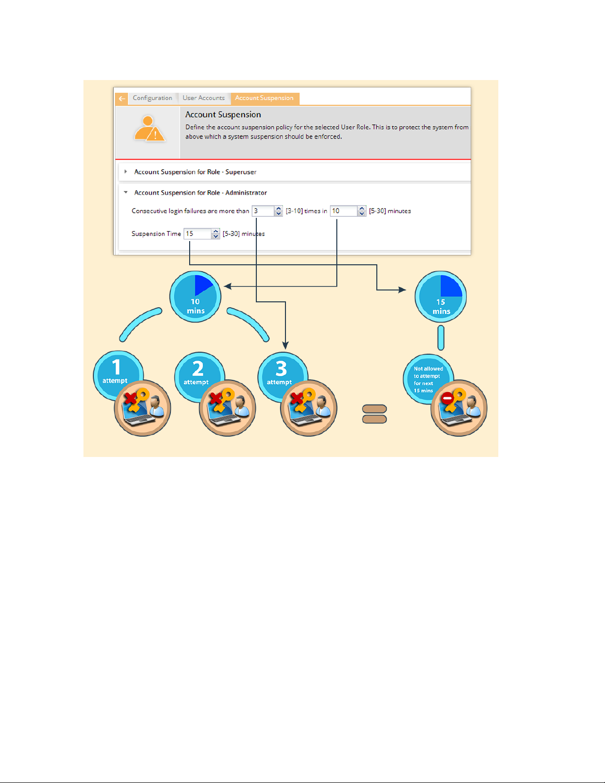
Account suspension protects the system from spurious logins through dictionary attacks. Define the
account suspension policy using the Configuration>User Accounts>Account Suspension option.
There are four roles available in the system- super user, administrator, viewer and operator. You can
configure different policies for each of these user roles. Configure the suspension time in minutes and the
number of failed login attempts during a specific time duration.
You can copy account suspension setting from one server to another when the servers are part of the
same server cluster.
To configure Account Suspension Setting for a user role, do the following.
Go to Configuration>User Accounts>Account Suspension.
1.
Specify a suspension time between 5 minutes and 30 minutes, during which the consecutive failed
1
login attempts happen.
Specify the number of failed login attempts between 3 and 10.
2
Click Save to save the changes made to the page.
3
The following diagrammatic representation explains the account suspension settings.
13
Page 25
AirTight Management Console User Guide
Account Suspension Settings
This policy is applicable on the root location only.
Copy Account Suspension Settings to Another Server
You can copy the account suspension settings from one server to another server when both servers are
part of the same server cluster. You can copy account suspension settings from child server to child
server, parent server to child server, or child server to parent server. You must be a superuser or an
administrator to copy policies from one server to another.
To copy account suspension settings, do the following.
Go to Configuration>User Accounts>Account Suspension on the parent server.
1.
Click Copy Policy. The Copy Policies dia log box appears.
2.
Select the server from which the account suspension settings are to be copied.
3.
Select the server to which the account suspension settings are to be copied.
4.
Click OK to copy the account suspension settings,
5.
Configure Login Parame t er s
14
Page 26

AirTight Management Console Conf ig ur ati on
You can specify the number of concurrent console logins that a user can have, along with the welcome
message that the user would see on logging on to AirTight Management Console. The user can have up
to 5 concurrent console logins.
You must have administrator privileges to configure login parameters.
You can copy the login configuration from one server to another server when both servers are part of the
same server cluster.
To configure login parameters, do the following.
Go to Configuration>System Settings>Login Configur ation,
1.
Enter the message that the user would see on the login screen, in Configure Login Message.
2.
To display the message on the login screen, select the Enable Login Message check box.
3.
Specify the number of concurrent sessions per user.
4.
Click Save to save the settings.
5.
Restore Defaults for Login Configuration
To restore default settings for login configuration, do the following.
Go to Configuration>System Settings>Login Configuration,
1.
Click Restore Defaults. Default settings are restored.
2.
Click Save to save the changes.
3.
Copy Login Configuration to Another Server
You can copy the login configuration from one server to another server when both servers are part of the
same server cluster. You can copy login configuration from child server to child server, parent server to
child server, or child server to parent server. You must be a superuser or an administrator to copy policies
from one server to another .
To copy login configuration, do the following.
Go to Configuration>System Settings>Login Configur ation on the parent server.
1.
Click Copy Policy. The Copy Policies dia log box appears.
2.
Select the server from which the login configuration is to be copied.
3.
Select the server to which the login configuration is to be copied.
4.
Click OK to copy the login configuration,
5.
15
Page 27

AirTight Management Console User Guide
Field
Description
Primary Server IP
Address/Hostname
The primary server IP address/Hostname of the LDAP
server.
(Primary Server) Port
The primary server port number of the LDAP
server.(Default:389).
Backup Server IP
Address/Hostname
The backup server IP address/Hostname of the LDAP
server.
(Backup Server) Po rt
The backup server port number of the LDAP server.
En
When this option is checked, only the SSL/TLS connection
server is allowed.
Verify LDAP Server’s Certificate
When this option is selected, the connection to the LDAP
User Authentication
Configure LDAP Server Parameters
AirTight Management Console ena bl es you to configure an LDAP server for user authentication. After an
LDAP server is configured, users or groups defined in the LDAP server can login to AirTight Management
Console.
In LDAP configuration, you can configure the following details.
LDAP Configuration parameters to be able to access the LDAP compliant directory
•
LDAP authentication details to search records on the LDAP server
•
Privileges for LDAP users- Here you specify the default role and the default locations assigned when
•
new LDAP users log in, for the case where the role and locations attributes are not provided by the
LDAP server. Note that the default values here apply to all users authenticated via LDAP. If the LDAP
server provides user role and locations attribute at the time of authentication, the attributes provided
by the LDAP server will override the default role and locations attributes.
You must have administrator privileges to configure the LDAP server access parameters.
Configure LDAP Server Access Parameters
To configure LDAP server access parameters, do the following.
Go to Configuration>User Accounts>LDAP Configuration option.
1.
Select Enable LDAP to enable user authentication using an LDAP compliant directory. All the fields
2.
related to LDAP are enabled on selecting this check box.
Enter the connection details as described in the following table.
3.
force Use of SSL/TLS
to the LDAP server is allowed. When it is not checked,
either of the Open or SSL/TLS connection to the LDAP
server is not allowed unless the certificate check passes.
When this option is not selected, the connection to the
LDAP server is allowed without verifying the LDAP server
certificate.
If you have selected Verify LDAP Server's Certificate, you must add a certificate. Click Add
4.
Certificate to add trusted root CA Certificate(s) for the LDAP server and choose the certificate.
Enter the LDAP configuration details as described in the following table.
5.
16
Page 28

Field
Description
Base Distinguished Name
The base distinguished name of the directory to which you
from the top of the DIT down to the entry in question.
Filter String
This is a mandatory argument. It is a string specifying the
You can also create a new group of users in AD with access
want to filter out any LDAP entry.
User ID Attribute
The string defined in the LDAP schema that the system
uses to identify the user.(Default: cn)
Field
Description
Admin User DN
The DN of the admin user to be used to authenticate in to
the LDAP server.
Append User DN
Select this option if the base DN specified in the LDAP
DN
Password
AirTight Management Console Conf ig ur ati on
want to connect, for example, o=democorp, c=au.
Distinguished Name is a unique identifier of an entry in the
Directory Information Tree (DIT). The name is the
concatenation of Relative Distinguished Names (RDNs)
attributes (existing or new) that the LDAP server uses to
filter users. For example, IsUser=A. By specifying a filter
string you can allow or disallow login access to a particular
OU or Group of user defined in the AD.
You can specify a DN (Distinguish Name) of any particular
group to allow access to only those who are member of that
group. For example, memberOf=DC=GroupName,DC=com.
You can include members from multiple groups by using an
OR condition. For example, to allow access to users under
Base DN who are member of any of the two groups, Airtight
Admins OR Airtight Reviewer, you must include the
following filter string:
(|(memberOf=CN=AirTight
Admins,DC=AirTight,DC=Com)(memberOf=CN=Airtight
Reviewer,DC=AirTight,DC=Com))
Similarly, to allow access to users under Base DN who are
member of both Airtight Admins AND Airtight Reviewer
groups, you must include the following filter string:
(&(memberOf=CN=AirTight
Admins,DC=AirTight,DC=Com)(memberOf=CN=Airtight
Reviewer,DC=AirTight,DC=Com))
You can have alternative configurations in AD such as,
adding a new attribute, say ATNWIFI, to the users in AD
that are granted access and then set filter string to allow
users with that attribute only. For example, filter string =
ATNWIFI
If the directory does not allow an anonymous search, you must configure user credentials to search
6.
the LDAP compliant directory. Configure the user credentials as described in the following table.
granted and include the group in filter string.
The most general filter string you can use is
'objectClass=*'.You can use this string when you do not
Configuration Details must be appended to the admin user
The password for the admin user.
17
Page 29

AirTight Management Console User Guide
Field
Description
User Role Attribute
The user role attribute string that the system uses to identify
a user’s role, as defined in the LDAP schema.
User Role
The default role for the new LDAP users. You can select
operator, viewer.
User Location Attribute
The user location attribute string that the system uses to
defined in your LDAP schema.
Locations
The location to which a new LDAP user has access rights.
You can select another location by clicking Change.
•
Click Test Settings to test the authentication options.
7.
Configure the default role and locations for new LDAP users. They are described in the following
8.
table.
one of the following four options- superuser, administrator,
identify the locations where the user is allowed access, as
Click Save to save the changes.
9.
Edit LDAP Server Access Parameters
To configure LDAP server access parameters, do the following.
Go to Configuration>User Accounts>LDAP Configuration option.
1.
Make the required changes.
2.
If you have made changes to the connection settings or the configuration settings, click Test
3.
Settings to ensure that the new details are valid.
Click Save to save the changes.
4.
Copy LDAP Configuration to Another Server
You can copy the LDAP configuration from one server to another server when both servers are part of the
same server cluster. You can copy LDAP configuration from child server to child server, parent server to
child server, or child server to parent server. You must be a superuser or an administrator to copy policies
from one server to another.
Note: When an LDAP configuration is copied to another server, the value of the Locations field in the
replicated policy on the destination server is set to 'root' (location).
To copy LDAP configuration, do the following.
Go to Configuration>User Accounts>LDAP Configuration on the parent server.
1.
Click Copy Policy. The Copy Policies dia log box appears.
2.
Select the server from which the LDAP configuration is to be copied.
3.
Select the server to which the LDAP configuration is to be copied.
4.
Click OK to copy the LDAP configuration.
5.
Configure RADIUS Parameters
AirTight Management Console can use a RADIUS server to facilitate user authentication. Configure the
RADIUS server access parameters using the Configuration->User Accounts->RADIUS Confi g u ration
option.
18
Page 30

AirTight Management Console Conf ig ur ati on
Select the Enable RADIUS Authentication check box to activate RADIUS authentication of users. You
can configure the Authentication,Accounting , and Advanced Settings after selecting this check box. Click
the respective option to view and edit the fields for the individual sections.
Configure Authentication Parameters
Configure access parameters for the RADIUS Authentication server using the Authentication section.
To configure access parameters for RADIUS authentication server, do the following.
Go to Configuration->User Accounts->RADIUS Configuration.
1.
Specify the IP address/ hostname, port number and shared secret for the primary and/or secondary
2.
RADIUS servers.
Click Test to test the connection to the RADIUS servers.
3.
Select Enable RADIUS Integration for CLI login to enable CLI user authentication using RADIUS.
4.
Select Enable RADIUS Integration for GUI login to enable GUI user authentication using RADIUS.
5.
Select vendor specific attributes as appropriate. These are used when vendor specific attributes are
6.
not defined for RADIUS server.
Click Save to save the changes.
7.
Configure Accounting Parameters
Configure accounting parameters for the RADIUS Accounting server under the Accounting section.
To configure accounting parameters for RADIUS authentication server, do the following.
Go to Configuration->User Accounts->RADIUS Configuration.
1.
Select the Enable RADIUS Accounting check box to enable RADIUS accounting.
2.
Specify the IP address/ hostname, port number and shared secret for the primary and/or secondary
3.
RADIUS accounting servers.
Click Save to save the changes.
4.
Configure Advanced Settings
Configure the realm (domain) for the CLI and GUI users using the Advanced Settings section. You can
also specify how the real name is to be appended to the user name (prefix notation or postfix
notation). Select the Use Prefix Notation check box to use a prefix notation. Postfix notation is used
when this check box is not selected.
To configure advanced settings, do the following.
Go to Configuration->User Accounts->RADIUS Configuration.
1.
Enter the realm for CLI users in CLI..
2.
Enter the realm for GUI users in GUI.
3.
Select the Use Prefix Notation check box to use a prefix notation. Postfix notation is used when this
4.
check box is not selected.
Click Save to save the changes made.
5.
Restore Default Settings
By default, RADIUS authentication is disabled. To restore this default setting, do the following.
Go to Configuration->User Accounts->RADIUS Configuration.
1.
19
Page 31

AirTight Management Console User Guide
Click Restore Defaults.
2.
Click Save to save the changes.
3.
Copy RADIUS Configuration to Another Server
You can copy the RADIUS configuration from one server to another server when both servers are part of
the same server cluster. You can copy RADIUS configuration from child server to child server, parent
server to child server, or child server to parent server. You must be a superuser or an administrator to
copy policies from one server to another.
Note: When a RADIUS configuration is copied to another server, the value of the Locations field in the
replicated policy on the destination server is set to 'root' (location).
To copy RADIUS configuration, do the following.
Go to Configuration>User Accounts>RADIUS Configuration on the parent server.
1.
Click Copy Policy. The Copy Policies dia log box appears.
2.
Select the server from which the RADIUS configuration is to be copied.
3.
Select the server to which the RADIUS configuration is to be copied.
4.
Click OK to copy the RADIUS configuration.
5.
Configure Parameter s for Certificate-based authentication
AirTight Management Console supports user authentication using digital certificates. Configure the
settings for user authentication using the Configuration>User Accounts>Cer tificate Configuration
option.
There are four ways to authenticate users - password only, certificate only, certificate and password and
certificate or password.
Password only: In this option, the user authentication is performed using the password. The user has to
enter the user name and the password at the login prompt. The password may be locally verified by the
system or may be verified using the external LDAP or RADIUS authentication service, as appropriate.
Certificate only: In this option, the user authentication is performed using the client certificate (such as
smart card). The user has to insert a smart card containing the client certificate in a reader attached to the
computer from where the console is accessed and then press the Login button. The system then verifies
the client certificate and obtains user identity (user name) from the certificate. Other attributes for the user
are retrieved either locally or from the external authentication services such as LDAP or RADIUS, as
appropriate. When this authentication option is set, the login screen appears as follows:
Certificate and Password: In this option, both the client certificate and the password are required for the
user authentication. The user has to insert a smart card containing the client certificate in a reader
attached to the computer from where the console is accessed, as well as enter the password at the login
prompt. The system verifies the password locally or using the external LDAP or RADIUS authentication
service, as appropriate. When this authentication option is set, the login screen appears as follows:
Certificate or Password: In this option, the user authentication is permitted either using the password or
using the client certificate. This option is appropriate for organizations which have only partially migrated
to using smart cards for authentication. At login prompt, the user can select certificate authentication by
checking the Use certificate for login box or continue with password authentication by entering login
name and password. When this authentication option is set, the login screen appears as follows:
20
Page 32

AirTight Management Console Conf ig ur ati on
Authentication optio n to activate
Check box to be selected
Enable certificate
based
authentication
Allow access without
certificate
Users must provide
password along with
certificate
Password only
No - -
Certificate only
Yes
No
No
Certificate and password
Yes
No
Yes
Certificate or password
Yes
Yes
No
The required authentication option can be activated based on the various combinations of the Enable
certificate based authentication box, Allow access without certificate box, and Users must provide
password along with certificate box.
The following table describes the activation of the authentication options based on the check boxes
selected by the user.
Note: In order to use certificate based authentication, it is necessary that the GUI host is able to access
the server at TCP port 4433. If there is a firewall between the GUI host and the server, port 4433 must be
opened from the host to the server.
When either Certificate only, Certificate and Pass wor d , or Certificate or Password option is activated, the
additional details should be provided as follows
• The field in the client certificate from which user identity can be retrieved by AirTight
Management Console.
• Root CA certificates to facilitate the verification of the client certificate.
• Preferred method to check for certificate revocation.
Restore Certificate Configuration Defaults
By default, certificate-based authentication is disabled.
To restore this default value, do the following.
Go to Configuration>User Accounts>Certificate Configuration.
1.
Click Restore Defaults.
2.
Click Save to save the changes.
3.
Copy Certificate Configuration to Another Server
You can copy the Certificate configuration from one server to another server when both servers are part
of the same server cluster. You can copy Certificate configuration from child server to child server, parent
server to child server, or child server to parent server. You must be a superuser or an administrator to
copy policies from one server to another.
To copy Certificate configuration, do the following.
Go to Configuration>User Accounts>Certificate Configuration on the parent server.
1.
Click Copy Policy. The Copy Policies d ia log box appe ar s.
2.
Select the server from which the certificate configuration is to be copied.
3.
Select the server to which the certificate configuration is to be copied.
4.
Click OK to copy the certificate configuration,
5.
21
Page 33

AirTight Management Console User Guide
Wireless Intrusion Prevention System
A Wi-Fi network is easy to set up by way of access points. Small plug-and-play devices can act as access
points. Smart phones and tablets that are now widely used, are also Wi-Fi enabled. They can act as
mobile hotspots. Wireless clients can connect to any such access points and easily access a network that
is not adequately protected against such wireless threats. Thus, a network can become vulnerable to
wireless attacks. It is therefore important to understand and control the authorized and unauthorized
access to networks.
A proper wireless intrusion prevention (WIPS) policy needs to be in place to prevent unauthorized access
to a network. The rules for wireless intrusion prevention into the network can be configured using
Configuration>WIPS.
You can set the rules for WIPS using the options seen under Configuration>WIPS.
AirTight Management Console provides you the flexibility to set a generic WIPS policy for all locations in
the organization, or a location-wise WIPS policy for individual locations. You can have WIPS activated at
some locations and deactivated at others.
Make sure that you have defined your location tree before you can proceed with WIPS configuration.
You must have administrator privileges to do the WIPS settings.
Specify the authorized WLAN policy templates to identify authorized APs, using
Configuration>WIPS>Authorized WLAN Policy. This is inherited, by default, from the parent location. It
can also be customized for a location.
Configure the policy to auto-classify the APs detected by AirTight WIPS, using Configuration>WIPS>AP
auto-classification. This is inherited, by default, from the parent location. It can also be customized for a
location.
Configure the policy to auto-classify clients detected by AirTight WIPS, using
Configuration>WIPS>Client auto-classification. This is inherited, by default, from the parent location. It
can also be customized for a location.
Define the intrusion prevention po lic y, using Configuration>WIPS>Intrusion Prevention. This is
inherited, by default, from the parent location. It can also be customized for a location.
Activate or deactivate intrusion prevention for the selected location, using
Configuration>WIPS>Intrusion Prevention Activation. This is location specific. You need to first select
the desired location from the location tree. Then you use the Intrusion Prevention Activation option to
activate or deactivate intrusion prevention for this location.
Import device lists that can be referred to for AP/Client classification, using Configuration>WIPS>Import
Devices. This is location specific. You need to first select the desired location from the location tree. Then
you use the Import Devices option to import devices for this location.
You can manage banned device list with the Configuration>WIPS>Banned Device List option.
You can manage hotspot SSID list with the Configuration>WIPS>Hotspot SSIDs option.
You can manage hotspot SSID list with the Configuration>WIPS>Vulnerable SSIDs option.
You can manage the smart device types used in smart device detection with the
Configuration>WIPS>Smart Device Types option.
You can lock the list of authorized AP and/or clients for a location using the
Configuration>WIPS>Device L ist Locking option.
22
Page 34

AirTight Management Console Conf ig ur ati on
Manage Authorized WLAN Polic y
Specify the Authorized WLAN policy templates for the selected location in the location hierarchy using
Configuration>WIPS>Authorized WLAN Policy.
Authorized WLAN policy for a location includes a set of one or more policy templates that define the
properties of one or more authorized wireless networks. A policy template is a collection of different
network related settings such as wireless network protocols, encryption protocol used, allowed network
SSIDs, security settings, authentication type used, allowed networks and so on. An authorized WLAN
policy also specifies what networks are restricted from having Wi-Fi APs on them. Apart from this, you
can also specify what APs to categorize as rogue or authorized APs based on their RSSI signal strength.
All these parameters together constitute an authorized WLAN policy.
The RSSI of a device is statistical parameter. Using the RSSI feature can cause legitimate neighborhood
APs to be classified as Rogues and subjected to containment if automatic prevention is enabled. This will
cause neighbor Wi-Fi disruption since clients, including the legitimate neighborhood clients, will NOT be
able to connect to the Rogue AP under containment.
Even if the intention is to use RSSI to identify APs that are within the facility, it will not always work since
low power APs such as soft APs, hotspot APs running on smart phones, USB APs, etc. or APs which are
away from RSSI measurement point will still not get classified as Rogue APs due to not meeting the RSSI
threshold.
Policy templates aid in the classification of APs. A new AP or an existing Authorized AP is compared
against the templates to determine if it is a rogue or misconfigured AP. Any AP at a location that does not
comply with the WLAN policy attached to that location, is not considered to be an authorized AP.
You must apply the templates from the available list for the WLAN policy at that location.
Authorized policy templates are used to identify authorized APs and constantly check that the actual Wi-
Fi access parameters provisioned on the authorized APs meet the security policy. You can define multiple
WLAN policy templates and assign them to each location. Any new AP that is added to a location is
verified on the basis of the WLAN policy templates attached to that location. Any mismatch is used to
detect misconfiguration of the Wi-Fi access network.
The system uses the details of the authorized Wi-Fi setup at a particular location to detect the presence
of misconfigured or rogue APs in your networ k.
An AP is considered as being compliant to the Authorized WLAN Policy if:
It is not connected to a No Wi-Fi network for its location
•
Its SSID matches with one of the templates attached at that location
•
Is connected to one of the networks specified in that template
•
• Conforms to the other settings in that template (except the Authentication Framework, as this setting
is not a property of the AP itself but of the backend authentication system).
Note: If the template specifies certain allowed AP capabilities (such as Turbo, 802.11n, and so on), the
AP may or may not have those capabilities. However, if a capability is not selected, the AP must not have
that capability to be considered as compliant.
With location-based policies, you can apply different sets of policy templates for different locations.
However, you cannot attach more than one template with the same SSID at any one location.
Only the policy templates that are applied to a location are used for AP classification at that location.
Other templates that are configured but not applied to the location, will not be used for AP classification,
as they are not a part of the WLAN policy for that location.
23
Page 35

AirTight Management Console User Guide
The authorized policy templates created at other locations can be applied to a selected location but
cannot be edited or deleted. The edit and delete operations are possible only at the location where the
template is created.
A child location automatically inherits the authorized WLAN policy from its parent. You can customize the
WLAN policy for a child location. You can also switch back to an inherited policy in case you have created
a customized policy.
Configure Authorized WLAN Policy
To configure an authorized WLAN policy for a location, do the following.
Select the location from the location tree.
1.
Go to Configuration>WIPS>Authorized WLAN Policy.
2.
If Wi-Fi has been deployed at the location, select the Wi-Fi is deployed at this location check box.
3.
The Policy Template and Select "No Wi-Fi" Networks sections on this page are enabled on
selecting this check box.
If you want to use an existing policy template, click the Applied icon for the existing policy tem plate to
4.
be applied to the location. Alternatively, Click Add New Policy Template if no policy template exists,
and add a new policy template. Refer to the Add Device Template or Edit Device Template
subsection in the Manage Policy Templates
template.
5. If there are any networks at the location that are not allowed to have APs connected to them,
a) Scroll down to the Select "No Wi-Fi" Networks section
b) Click Add. The Add Networks dialog box appears.
c) Enter the SSID or IP address of the network to add.
Define RSSI based classification, if the WIPS is intended for use in an isolated environment without
6.
much of a neighborhood activity like defense and military facilities. It is recommended to skip this
section altogether in case of commercial or business district environments. Either of the following two
mechanisms must be switched on to classify the APs.
a) Enter the threshold RSSI value to use for preclassification of APs with signal strength stronger
than this value as rogue or unauthorized APs.
b)Select the Preclassify APs connected to monitored subnets as Rogue or Authorized APs to
preclassify the APs connected to monitored subnets as rogue or authorized APs.
Click Save to save the changes.
7.
section for details on how to add or edit a policy
Edit Authorized WLAN Policy
To edit an authorized WLAN policy for a location, do the following.
Select the location from the location tree.
1.
Go to Configuration>WIPS>Authorized WLAN Pol icy.
1
If you want to apply an existing policy, click the Applied icon for that policy in the policy template list.
2.
If you want to make changes to the policy template, click the policy template link in the policy
3.
template list. If you want to add a new policy template click Add New Policy Template, and add a
new policy template. Refer to the Add Device Template or Edit Device Template subsections in the
Manage Policy Templates
4. If there are any networks at the location that are not allowed to have APs connected to them,
a) Scroll down to the Select "No Wi-Fi" Networks section
b) Click Add. The Add Networks dialog box appears.
c) Enter the SSID or IP address of the network to add.
Define RSSI based classification, if the WIPS is intended for use in an isolated environment without
5.
much of a neighborhood activity like defense and military facilities. It is recommended to skip this
24
section for details on how to add or edit a policy template.
Page 36
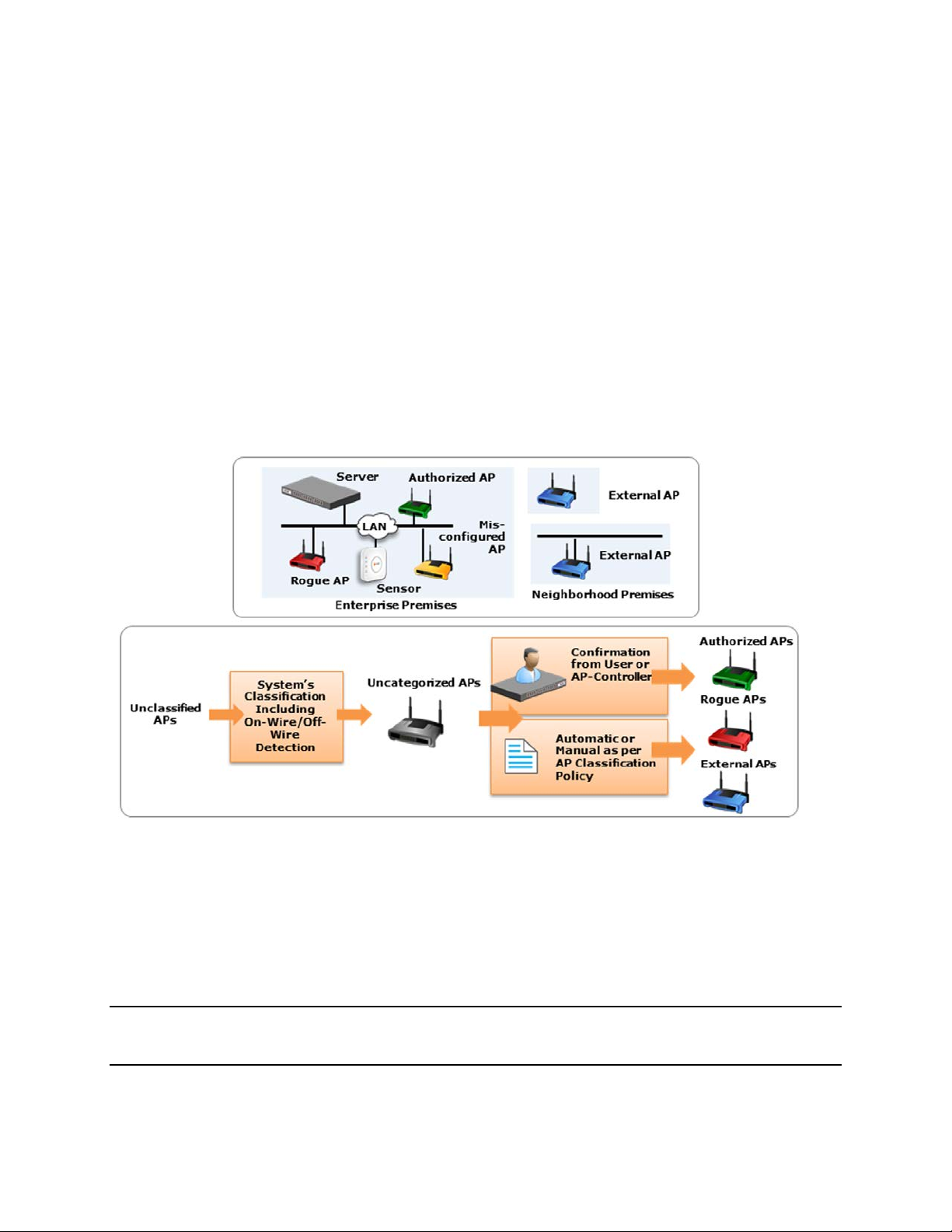
AirTight Management Console Conf ig ur ati on
section altogether in case of commercial or business district environments. Either of the following two
mechanisms must be switched on to classify the APs.
a) Enter the threshold RSSI value to use for preclassification of APs with signal strength stronger
than this value as rogue or unauthorized APs.
b)Select the Preclassify APs connected to monitored subnets as Rogue or Authorized APs to
preclassify the APs connected to monitored subnets as rogue or authorized APs.
Click Save to save the changes.
6.
Configure AP Auto-classification Policy
The AP Auto-Classification policy function enables you to specify the AP classification policy for different
AP categories.
It is important to know about the authenticity of APs in the network as unauthorized APs can cause
irreparable damage to your network and business.
AP classification is of prime importance in WIPS implementation.
A diagrammatic representation of AP classification is shown below.
AP classification
Under External APs, AirTight recommends that you select Automatically move Potentially External APs in
the Uncategorized list to the External Folder. The system automatically removes an AP from the External
folder and moves it to an appropriate AP folder if it later detects that the AP is wired to the enterprise
network.
Under Rogue APs, AirTight recommends that you select Automatically move Potentially External APs in
the Uncategorized list to the Rogue folder.
Note: Once you move an AP to the Rogue folder, the system never automatically removes it from the
Rogue folder, even if it later detects that the AP is unwired from the enterprise network or its security
settings have changed.
25
Page 37
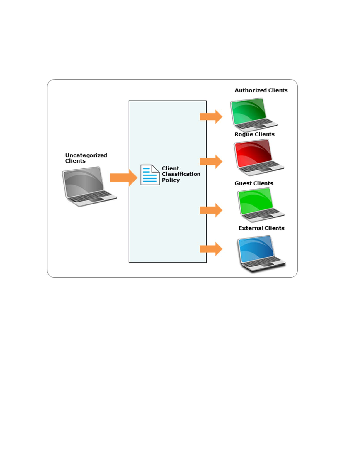
AirTight Management Console User Guide
Configure Client Auto-classification Policy
The client auto-classification policy determines how clients are classified upon initial discovery and
subsequent associations with APs.
Client auto classificatio n
Define how the system should automatically classify the detected wireless clients at the selected location
based on their initial discovery and subsequent AP associations. This policy is automatically inherited by
child locations of the selected location. The intrusion prevention actions enforced on the wireless clients
are based on their classification in the system.
If a client is ever manually classified, then it is never automatically classified by the system until it is
deleted from the system and rediscovered.
Under Initial Classification, select the Automatically classify newly discovered Clients at this
location as check box and specify if newly discovered clients at a particular location, which are
Uncategorized by default should be classified as External, Authorized or Guest.
Under Automatic Client Classification, select one or more options to enable the system automatically reclassify Uncategorized and Unauthorized Clients based on their associations with APs. You can
categorize the following types of clients.
Clients running AirTight Mobile
•
All External Clients running AirTight Mobile are classified as Authorized
•
All Uncategorized Clients running AirTight Mobile are classified as Authorized
•
All Rogue Clients running AirTight Mobile are classified as Authorized
•
26
Page 38
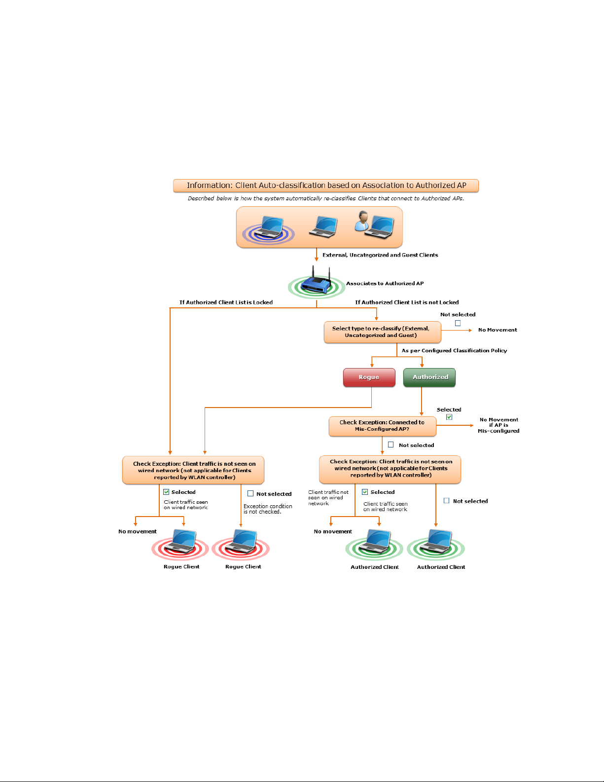
All Guest Clients running AirTight Mobile are classified as Authorized
•
Clients connecting to Authorize d APs
•
All External Clients that connect to an Authorized AP are re-classified as Authorized
•
All Uncategorized Clients that connect to an Authorized AP are reclassified as Authorized
•
All Guest Clients that connect to an Authorized AP are reclassified as Authorized
•
You can select the following exceptions.
Do not reclassify a Client connecting to a Misconfigured AP as Authorized
•
Do not reclassify a Client if its wireless data packets are not detected on the wired network
•
(except if the connection is reported by WLAN controller).
AirTight Management Console Conf ig ur ati on
Classification for clients connecting to Authorized APs
Click Advanced to configure the auto classification settings for clients connecting to guest APs and
external APs.
Clients connecting to Guest APs
•
All External Clients that connect to a Guest AP are reclassified as Guest
•
All Uncategorized Clients that connect to a Guest AP are reclassified as Guest
•
You can select the following exceptions
Do not re-classify a Client connecting to a Mis-configured AP as Guest
•
Do not re-classify a Client as Guest if its wireless data packets are not detected on the wired
•
network (except if the connection is reported by WLAN controller)
27
Page 39
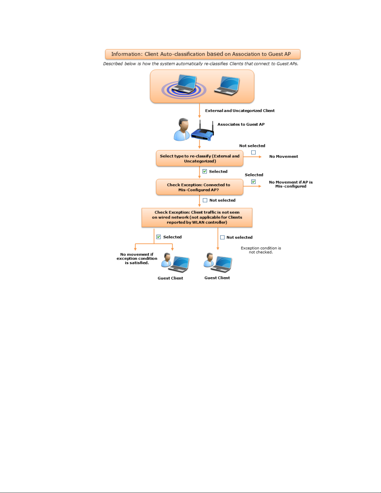
AirTight Management Console User Guide
Classification for Clients connecting to Guest APs
Clients connecting to External APs
•
All Uncategorized Clients that connect to an External AP are reclassified as External
•
All Uncategorized Clients that connect to a Potentially External AP are classified as External
•
All Guest Clients that connect to an External AP are re-classified as External
•
All Guest Clients that connect to a Potentially External AP are re-classified as External
•
28
Page 40
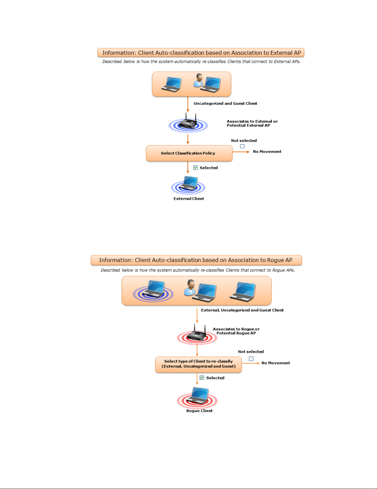
AirTight Management Console Conf ig ur ati on
Classification of Clients connecting to External APs
Clients connecting to Rogue APs
•
All Clients other than Authorized Clients that connect to a Rogue AP are (re)classified as
•
Rogue
All Clients other than Authorized Clients that connect to a Potentially Rogue AP are classified
•
as Rogue
Classsification of Clients connecting to Rogue APs
29
Page 41
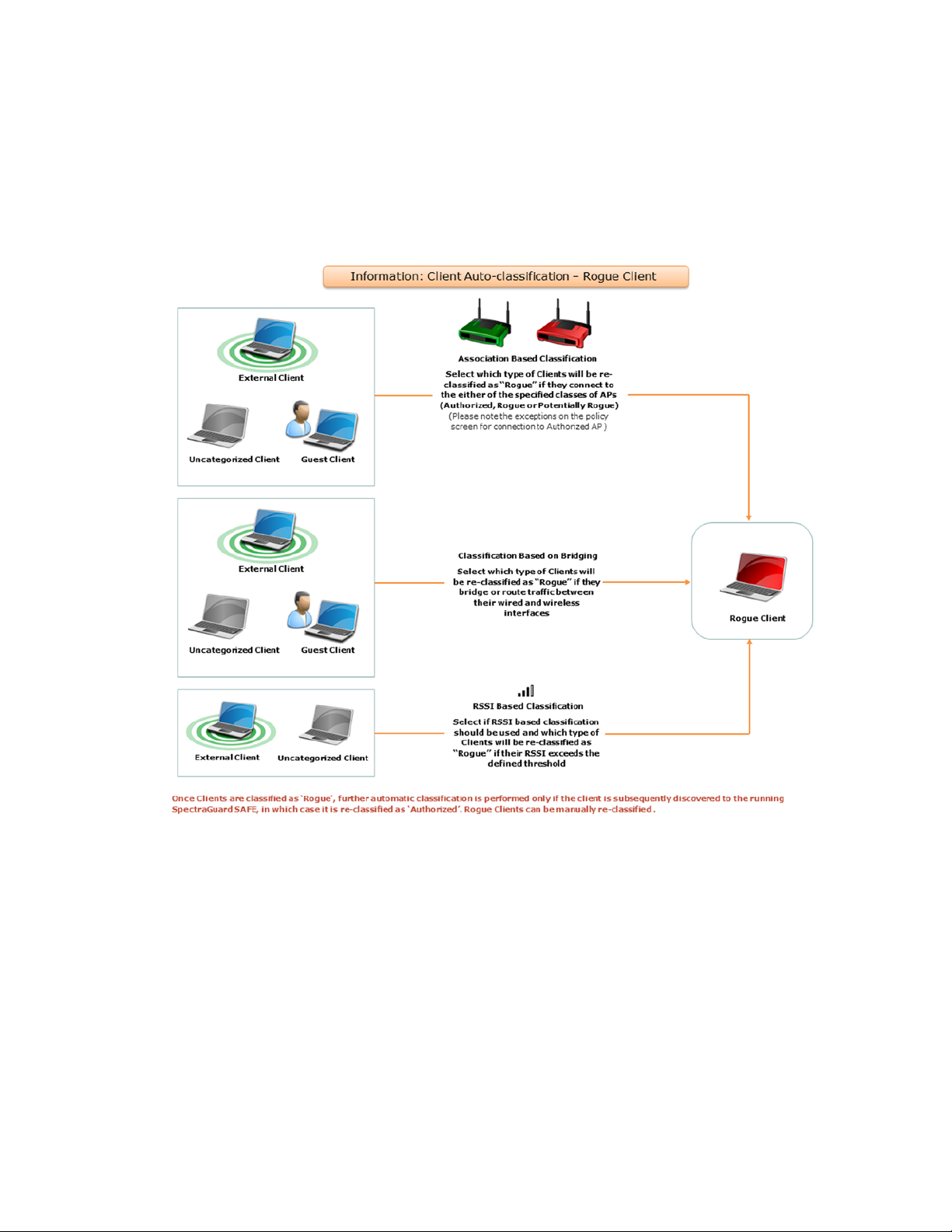
AirTight Management Console User Guide
Bridging to the Corporate Network
•
Classify any non-authorized Client as Rogue if it is detected as bridging Wi-Fi to the corporate
•
network
RSSI Based Classification
•
You can enable RSSI based client classification for uncategorized clients and/or external clients
and configure RSSI based classification for them. Specify a RSSI threshold and the category for
such clients.
Classification of Clients bridging to corporate network and RSSI based classification
Intrusion Prevention
The Intrusion Prevention Policy determines the wireless threats against which the system protects the
network automatically. The system automatically moves such threat-posing APs and Clients to
quarantine. The system can protect against multiple threats simultaneously based on the selected
Intrusion Prevention level.
If the server quarantines an AP or Client based on the Intrusion Prevention policy, the Disable Autoquarantine option ensures that the system will not automatically quarantine this AP or Client (regardless
of the specified Intrusion Prevention policies).
AirTight Management Console can prevent any unwanted communication in your 802.11 network. It
provides you various levels of prevention-blocking mechanisms of varying effectiveness. Intrusion
30
Page 42

AirTight Management Console Conf ig ur ati on
Prevention Level enables you to specify a trade-off between the desire d lev el of preventi on and the
desired number of multiple sim ultaneous prev ent ions a c ros s radio channe ls.
The greater the number of channels across which simultaneous prevention is desired, the lesser is the
effectiveness of prevention in inhibiting unwanted communication. Scanning for new devices continues
regardless of the chosen prevention level.
You can select from the following intrusion prevention levels:
Block: A single sensor can block unwanted communication on any one channel in the 802.11b/g band
•
and any one channel in the 802.11a band.
Disrupt: A single sensor can disrupt unwanted communication on any two channels in the 802.11b/g
•
band and any two channels in the 802.11a band.
Interrupt: A single sensor can interrupt unwanted communication on any three channels in the
•
802.11b/g band and any three channels in the 802.11a band.
Degrade: A single sensor can degrade the performance of unwanted communication on any four
•
channels in 802.11b/g band and any four channels in the 802.11a band.
Block is the most powerful prevention level, that is, it can severely block almost all popular Internet
applications including ping, SSH, Telnet, FTP, HTTP, and the like. However, at this level, a single sensor
can simultaneously prevent unwanted communication on only one channel in the 802.11b/g band and
one channel in the 802.11a band. If you want the sensor to prevent unwanted communication on multiple
channels simultaneously in the 802.11 b/g and/or the 802.11a band, you must select other prevention
levels.
Note: Prevention Type determines the blocking strength to prevent communication from unwanted APs
and Clients. The system can prevent multiple APs and Clients on each channel. Prevention Type is not
applicable for Denial of Service (DoS) attacks or ad hoc networks. You must select a lower blocking level
to prevent devices on more channels. Choosing a lower blocking level means that some packets from the
blocked device may go through.
You can enable intrusion prevention against the following threats
Rogue APs: APs connected to your network but not authorized by the administrator; an attacker can
•
gain access to your network through the Rogue APs. You can also automatically quarantine
uncategorized, indeterminate and banned APs connected to the network.
Misconfigured APs: APs authorized by the administrator but do not conform to the security policy; an
•
attacker can gain access to your network through misconfigured APs. This could happen if the APs
are reset, tampered with, or if there is a change in the security policy.
Client Misassociations: Authorized Clients that connect to rogue or external (neighboring) APs;
•
corporate data on the authorized client is under threat due to such connections. AirTight recommends
that you provide automatic intrusion prevention against authorized clients that connect to rogue or
external APs.
There is a special intrusion prevention policy for the smart devices that are not approved. Even if a
current client policy restricts authorized clients from connecting to a guest AP, an unapproved smart
device can still be allowed to do so. One needs to explicitly allow or restrict unapproved smart devices
from connecting to a guest AP.
Click Special Handling for Smart Devices to enable special handling for unapproved smart devices.
You can allow the unapproved smart device to connect to a guest AP only. To do this,
Select Enable Special Handling for Unapproved Smart Devices.
1.
Select Allow connection to Guest AP, but not Authorized AP.
2.
To disallow the unapproved smart device from connecting to both a guest AP as well as an authorized
AP, select Do not allow connection to Guest AP and Authorized AP.
31
Page 43
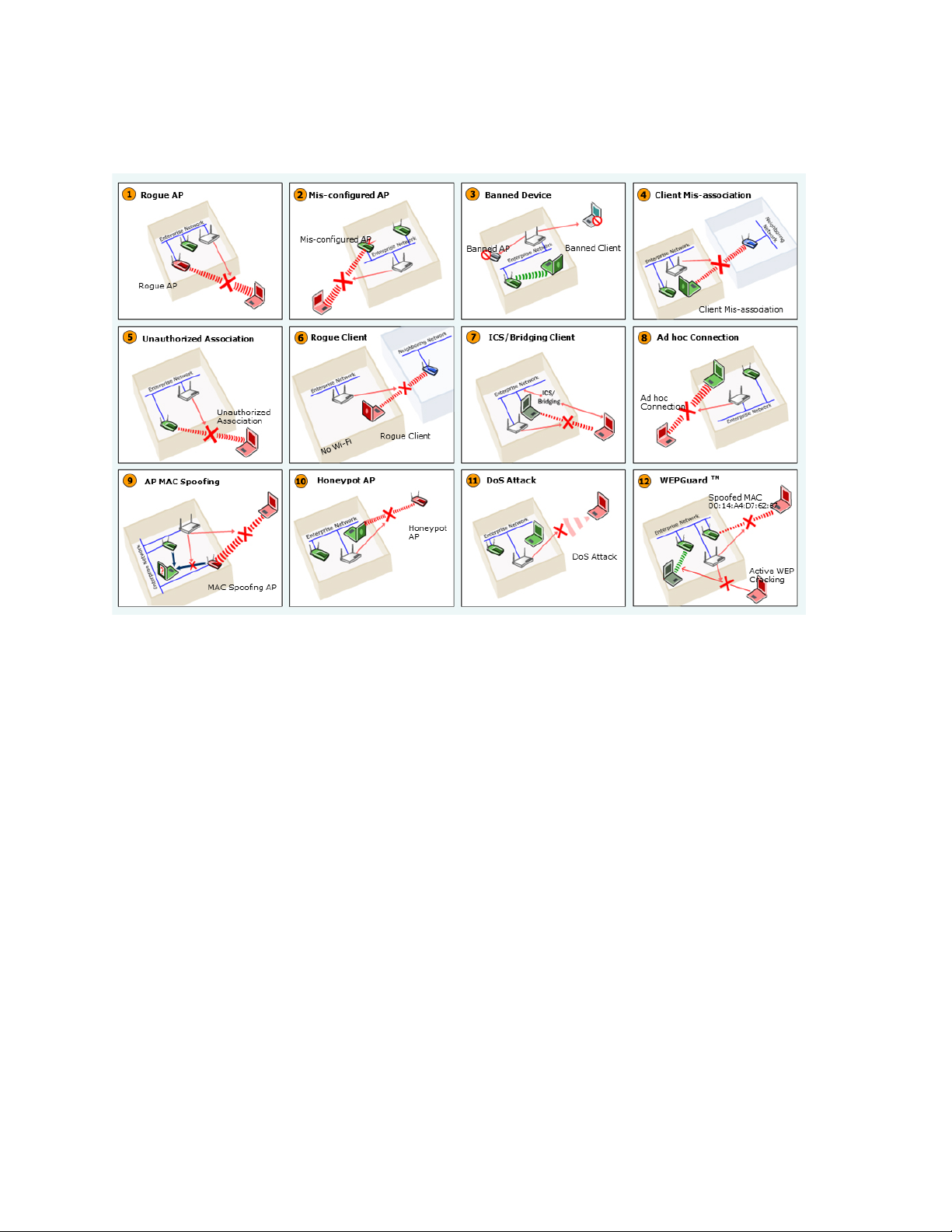
AirTight Management Console User Guide
Wireless Threats
Following is a diagrammatic representation of the various wireless threats.
Wireless Threats
Non-authorized Associations: Non-authorized and Banned Clients that connect to Authorized APs; an
attacker can gain access to your network through Authorized APs if the security mechanisms are weak.
Non-authorized or Uncategorized Client connections to an Authorized AP using a Guest SSID are not
treated as unauthorized associations.
• Associations to Guest APs: External and Uncategorized Clients that connect to Guest APs are
classified as Guest Clients. The Clients connected to a wired network or a MisConfigured AP can be
specified as exceptions to this policy.
• Ad hoc Connections: Peer-to-peer connections between Clients; corporate data on the Authorized
Client is under threat if it is involved in an ad hoc connection.
• MAC Spoofing: An AP that spoofs the wireless MAC address of an Authorized AP; an attacker can
launch an attack through a MAC spoofing AP.
• Honeypot/Evil Twin APs: Neighboring APs that have the same SSID as an Authorized AP; Authorized
Clients can connect to Honeypot/Evil Twin APs. Corporate data on these Authorized Clients is under
threat due to such connections.
• Denial of Service (DoS) Attacks: DoS attacks degrade the performance of an official WLAN.
• WEPGuard TM: Active WEP cracking tools allow attackers to crack the WEP key and gain access to
confidential data in a matter of minutes or even seconds. Compromised WEP keys are used to gain
entry into the authorized WLAN by spoofing the MAC address of an inactive Authorized Client.
• Client Bridging/ICS: A Client with packet forwarding enabled between wired and wireless interfaces. An
authorized Client bridging and unauthorized/uncategorized bridging Client connected to enterprise
subnet is a serious security threat.
Activate Intrusion Preventi on f or Loc a t ion
32
Page 44
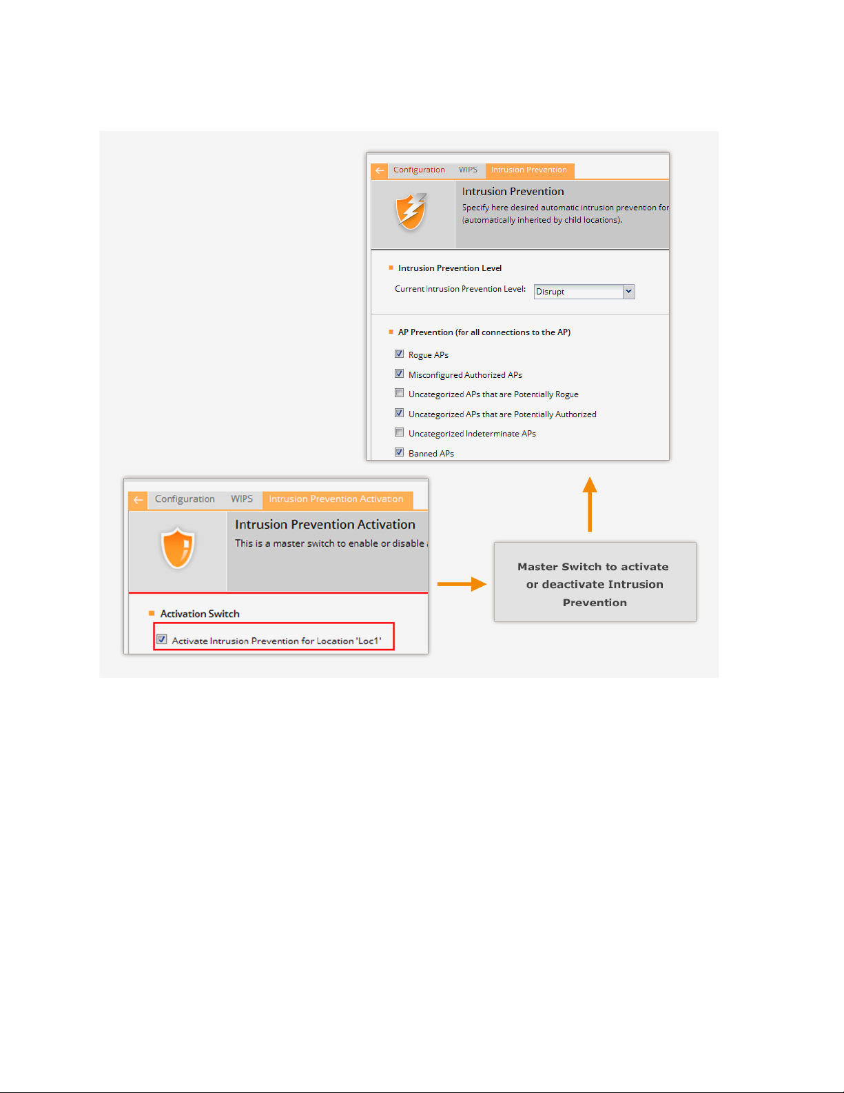
AirTight Management Console Conf ig ur ati on
Activate intrusion prevention for a location using the Configuration>WIPS>Intrusion Prevention
Activation option. The following figure explains intrusion preve nti on acti vat ion.
Intrusion Prevention Activation
The intrusion prevention policy is a location specific policy - it cannot be inherited from the parent
location.
Authorized APs should be in the Authorized folder before activating intrusion prevention. Their network
connectivity icon may show the status as Wired, Unwired, or Indeterminate.
If you deploy new Authorized APs later, you do not have to deactivate intrusion prevention. However, you
need to ensure that the newly deployed APs are moved to the Authorized folder.
AirTight recommends that you select the Activate Intrusion Prevention for <location> check box for
the selected location only after the deployment is stable and fully configured. If you are modifying a
deployment, clear the Activate Intrusion Prevention for <location> check box to avoid spurious activity
during the transient phase.
Click Save to the change. Click Cancel to cancel the change. Click Restore Defaults to restore the
default value.
Import Device List
33
Page 45

AirTight Management Console User Guide
Importing an authorized AP List and an authorized or unauthorized client list is an efficient alternative to
manual movement of these devices into the authorized / unauthorized bins. After successfully importing
these lists, the system automatically classifies the APs and Clients in the respective lists as authorized or
unauthorized.
This is a location specific property and cannot be inherited from the parent location folder. You need
administrator rights to import a device list.
You can import authorized AP list, authorized client list, guest client list, rogue client list, and AirTight
device list into AirTight Management Console using the Configuration>WIPS>Import Devices option.
Format of the .txt or.csv file co n taining the AP/Client data
Each line has comma separated list of MAC Address, IP Address, Device Name. For example,
11:11:11:11:11:11,192.168.8.1,name1
11:11:11:11:11:12,192.168.8.2,name2
11:11:11:11:11:13,192.168.8.3,name3
11:11:11:11:11:14,192.168.8.4,name4
11:11:11:11:11:15,192.168.8.5,name5
11:11:11:11:11:16,192.168.8.6,name6
11:11:11:11:11:17,192.168.8.7,name7
Format of.txt or .csv file containing th e AirTight Device data
Each line has comma separated list of MAC Address, Device Name. For example,
44:77:11:22:44:77, name1
44:77:11:22:11:12, name2
44:77:11:22:11:13, name3
44:77:11:22:11:14, name4
44:77:11:22:11:15, name5
Points to remember
Once you move an AP to the Authorized folder, AirTight Management Console never removes it from
•
the Authorized folder automatically, even if the AP is unwired from the enterprise network.
When you import APs from the list, policy settings in the Setup Wizard do not affect these APs.
•
When you import sensors from the list, you can delete these sensors only from the Devices page.
•
When you import clients from the list, policy settings in the Setup Wizard do not affect these clients.
•
To import devices, do the following.
Select the appropriate option from the Import list box, depending on whether you want to import an
1.
authorized AP list, an authorized client list, a guest client list, a rogue client list, or a sensor list. The
text on the command button below the device list changes based on your selection. For instance, if
you select the option Import Authorized Client List from the list box, the text on the command
button changes to Import Authorized Client List.
Under the Auto Tag Devices area, select Auto tag Devices to automatically tag the device(s) to the
2.
selected location. Select Manually Tag Devices to, to manually tag the device(s) to the selected
location.
Enter the MAC address, IP address and name of the AP or client. If the device is a sensor, enter the
3.
MAC address and the name of the sensor. Alternatively, you can specify a filename containing the
AP/client/sensor data. Click Autofill using File, and select the .txt or .csv file containing the
AP/client/sensor data.
Click Import Authorized AP List to import the list of authorized APs. Click Import Authorized Client
4.
List to import the list of authorized clients. Click Import Guest Client List to import the list of guest
34
Page 46

AirTight Management Console Conf ig ur ati on
clients. Click Import Rogue Client List to import the lists of rogue clients. Click Import Sensor List
to import the list of sensors. The file has to be a text file or a csv file. Refer to the subsequent sections
for the text and csv file formats for the AP, client and sensor lists.
Once imported successfully, the devices are seen under their respective tabs on the Devices page. The
Dashboard page also reflects the activity of the newly imported sensors, APs, and clients.
Delete device details from device list
To delete the device details from the device list, do the following.
Select the AP/client/sensor row and click the corresponding Delete hyperlink.
1.
Click Yes when asked to confirm deletion.
2.
Manage Banned Device List
You can create and manage a list of banned APs and banned clients using the
Configuration>WIPS>Banned Device List option. If the devices from this list are detected, they are not
classified as rogue devices.
Create banned AP list
You can add the wireless MAC addresses of APs that are blacklisted in your organization. If APs with
these MAC addresses become visible, AirTight Management Console generates an alert.
You can either enter individual AP MAC addresses or to import a list of banned APs in to the database.
To add an individual AP MAC address, do the following.
Go to Configuration>WIPS>Banned Device List.
1.
Click to expand Banned AP List.
2.
Click Add MAC Address. The Add to Banned List dialog box appears.
3.
Click Add MAC Address under Banned AP list and enter the MAC Address of a banned AP. You can
4.
add one or more banned AP MAC addresses in this manner.
You can also import a list of AP MAC addresses from a file. The file containing the list of AP MAC
addresses must be a CSV file.
To import a file containing a list of AP MAC addresses, do the following.
Go to Configuration>WIPS>Banned Device List
1.
Click to expand Banned AP List.
2.
Click Add MAC Address. The Add to Banned List dialog box appears.
3.
Click File Upload.
4.
Click Choose File to choose the file and then click Upload to upload the selected file.
5.
Click Add to add the imported AP MAC addresses to the banned device list.
6.
Create banned Client list
You define the wireless MAC addresses of Clients that are blacklisted in your organization. For example,
such MAC addresses could belong to laptops of employees who are no longer with the organization. If
APs with these MAC addresses become visible, AirTight Management Console generates an alert.
35
Page 47

AirTight Management Console User Guide
You can either enter individual client MAC addresses or to import a list of banned clients to the database.
To add an individual client MAC address, do the following.
Go to Configuration>WIPS>Banned Device List.
1.
Click to expand Banned Client List.
2.
Click Add MAC Address. The Add to Banned List dialog box appears.
3.
Click Add Device link to add a MAC address manually.
4.
Enter the MAC address to add. You can add one or more banned client MAC addresses in this
5.
manner.
Click Add to add the devices to the banned device list.
6.
You can also import a list of client MAC addresses. The file containing the list of client MAC addresses
must be a CSV file.
To import a file containing a list of client MAC addresses, do the following.
Go to Configuration>WIPS>Banned Device List.
1.
Click to expand Banned Client List.
2.
Click Add MAC Address. The Add to Banned List dialog box appears.
3.
Click File Upload.
4.
Click Choose File to choose the file and then click Upload to upload the selected file.
5.
Click Add to add the imported client MAC addresses to the banned device list.
6.
Delete Banned Device
1. Go to Configuration>WIPS>Banned Device List.
Click the Delete link for the device to be deleted. A confirmation message is displayed to confirm
2.
deletion.
Click Yes to confirm deletion
3.
Copy Banned Device List to Another Server
You can copy the banned device list from one server to another server when both servers are part of the
same server cluster. You can copy banned device list from child server to child server, parent server to
child server, or child server to parent server. You must be a superuser or an administrator to copy policies
from one server to another.
To copy banned device list, do the following.
Go to Configuration>WIPS>Ba n n ed Device List on the parent server.
1.
Click Copy Policy. The Copy Policies dia log box appe ar s .
2.
Select the server from which the banned device list is to be copied.
3.
Select the server to which the banned device list to be copied.
4.
Click OK to copy the banned device list,
5.
Manage Hotspot SSIDs
Configure and manage a list of hotspot SSIDs using the Configuration->WIPS-> Advanced Settings>Hotspot SSIDs option.
It is highly likely that hotspot APs are present in the enterprise neighborhood. If enterprise Client probes
for well known hotspot SSID, it is at risk of connecting to the hotspot AP without the user necessarily
knowing about it. Also if enterprise AP uses hotspot SSID on it, such an AP may attract undesirable
Clients to connect to it.
36
Page 48

AirTight Management Console Conf ig ur ati on
If you consider an SSID to be vulnerable to hack ers , you can open the Hotspot SSIDs screen and enter
the SSID under SSID (ASCII character string).
Add Hotspot SSIDs
The system lists commonly known SSIDs by default. To enter a blank SSID: that is, with no string, click
<Add> without entering any text. The list shows the SSID as NULL.
To add a hotpsot SSID, do the following.
Go to Configuration>WIPS>Advanced Settings>Hots p o t SSID.
1.
Click Add New Hotspot SSID. The Add New Hotspot SSID dialog box appears.
2.
Enter a new hotspot SSID and click OK. If an AP with a hotspot SSID is detected, the system
3.
generates an event.
Search Hotspot SSIDs
To search for hotspot IDs, do the following.
Go to Configuration>WIPS>Advanced Settings>Hots p o t SSID.
1.
Type in the search string in the search SSID box and press the Enter key. A list of hotspot SSIDs
2.
matching the search criteria appears.
To clear the search string, click the x icon next to the search SSID box.
Delete Hotspot SSID
To delete hotspot SSIDs, do the following.
Go to Configuration>WIPS>Advanced Settings>Hotspot SSID.
1.
click Delete link for the SSID to be deleted.
2.
Click Yes on the confirmation message to confirm the deletion of the hotspot SSID.
3.
Restore Default Hotspot SSID list
To restore the default hotspot SSID list, do the following.
Go to Configuration>WIPS>Advanced Settings>Hots p o t SSIDs
1.
Click Restore Defaults. A confirmation message prompting you to confirm the operation appears.
2.
Click Yes. The default hotspot SSID list is restored.
3.
Copy Hotspot SSID List to Another Server
You can copy the list of hotspot SSIDs from one server to another server when both servers are part of
the same server cluster. You can copy a list of hotspot SSIDs from child server to child server, parent
server to child server, or child server to parent server. You must be a superuser or an administrator to
copy policies from one server to another.
To copy a list of hotspot SSIDs, do the following.
Go to Configuration>WIPS>Advanced Settings>Hots p o t SSIDs on the parent server.
1.
Click Copy Policy. The Copy Policies dia log box appears.
2.
Select the server from which the list of hotspot SSIDs is to be copied.
3.
37
Page 49

AirTight Management Console User Guide
Select the server to which the list of hotspot SSIDs is to be copied.
4.
Click OK to copy the list of hotspot SSIDs.
5.
Manage Vulnerable SSIDs
Configure and manage a list of vulnerable SSIDs using the Configuration>WIPS>Advanced
Settings>Vulnerable SSIDs option.
APs have well known default SSIDs and many users may not change these SSIDs when deploying the
APs. Therefore it is highly likely that APs using default SSIDs are present in the enterprise neighborhood.
If an enterprise Client probes for a default SSID, it is at risk of connecting to the neighborhood AP without
the user necessarily knowing about it. Also if an enterprise AP uses a default SSID, such an AP may
attract undesirable clients to connect to it.
Add Vulnerable SSID
If you consider an SSID to be vulnerable to hackers, you can add the SSID to the Vulnerable SSIDs list.
To add a vulnerable SSID, do the following.
Go to Configuration>WIPS>Advanced Settings>Vulnerable SSIDs.
1.
Click Add New Vulnerable SSID.
2.
Enter the SSID and click OK to add it to the list of vulnerable SSIDs. If an AP point with a vulnerable
3.
SSID is detected, the system generates an event.
Note: Commonly known SSIDs are listed by default. To enter a blank SSID: no string, click Add without
entering any text. The list shows the SSID as NULL.
Search Vulnerable SSID
To search a vulnerable SSID, do the following.
Go to Configuration->WIPS-> Advanced Settings->Vulnerable SSIDs
1.
Type in the search string in the search SSID box and press the Enter key. A list of vulnerable SSIDs
2.
matching the search criteria is displayed.
To clear the search string, click the x icon next to the search SSID box.
Delete Vulnerable SSID
To delete a vulnerable SSID, do the following.
Go to Configuration->WIPS-> Advanced Settings->Vulnerable SSIDs
1.
Click Delete link for the SSID to be deleted.
2.
Click Yes on the confirmation message to confirm the deletion of the vulnerable SSID.
3.
Restore Default Vulnerable SSID list
To restore the default vulnerable SSID list, do the following.
Go to Configuration>WIPS>Advanced Settings>Vulnerable SSIDs
1.
Click Restore Defaults. A confirmation message prompting you to confirm the operation appears.
2.
38
Page 50

AirTight Management Console Conf ig ur ati on
Click Yes. The default vulnerable SSID list is restored.
3.
Copy Vulnerable SSID List to Another Server
You can copy the list of vulnerable SSIDs from one server to another server when both servers are part of
the same server cluster. You can copy a list of vulnerable SSIDs from child server to child server, parent
server to child server, or child server to parent server.
You must be a superuser or an administrator to copy policies from one server to another.
To copy a list of vulnerable SSIDs, do the following.
Go to Configuration>WIPS>Advanced Settings>Vulnerable SSIDs on the parent server.
1.
Click Copy Policy. The Copy Policies dia log box appears.
2.
Select the server from which the list of vulnerable SSIDs is to be copied.
3.
Select the server to which the list of vulnerable SSIDs is to be copied.
4.
Click OK to copy the list of vulnerable SSIDs.
5.
Manage Smart Device Types
You can view, add, and delete the smart device types using the Configuration->WIPS-> Advanced
Settings->Smart Device Type option.
The Smart Device Type page shows the system-defined smart device types, and the user-defined smart
device types, if any.
Add Smart Device Type
You can add to the list of predefined smart device types.
To add a new smart device type, do the following.
Go to Configuration>WIPS>Advanced Settings>Smar t Device Type.
1.
Click Add new smart device type. The Add new smart device type dialog box appears.
2.
Enter the Smart Device Type.
3.
Click OK to add the smart device type to the existing list of smart device types.
4.
Delete Smart Device Type
You can delete only the smart device types that have been manually added. You cannot delete the
system-defined smart device types.
To delete a user-defined smart device type, do the following.
Go to Configuration>WIPS>Advanced Settings>Smar t Device Type
1.
Select the smart device type and click Delete. A message appears prompting you to confirm the
2.
deletion.
Click Yes to confirm the deletion.
3.
Copy Smart Device Types List to Another Server
You can copy the list of smart device types from one server to another server when both servers are part
of the same server cluster. You can copy a list of smart device types from child server to child server,
39
Page 51

AirTight Management Console User Guide
parent server to child server, or child server to parent server. You must be a superuser or an
administrator to copy policies from one server to another.
To copy a list of smart device types, do the following.
Go to Configuration>WIPS>Advanced Settings>Smar t Device Type on the parent server.
1.
Click Copy Policy. The Copy Policies dia log box appears.
2.
Select the server from which the list of smart device types is to be copied.
3.
Select the server to which the list of smart device types is to be copied.
4.
Click OK to copy the list of smart device types.
5.
40
Page 52

AirTight Management Console Conf ig ur ati on
Manage WiFi Access
Wi-Fi profiles are used to define the Wi-Fi configuration of an AirTight Device in access point (AP) mode.
Wi-Fi Profiles are applied onto a radio of a device. The radio and the device must support access point
configuration.
Wi-Fi Profiles can be created on any location.
Wi-Fi profile is a Wi-Fi network profile. The profile is a set of configuration parameters related to a
wireless or Wi-Fi network. It consists of security, network, captive portal, firewall, traffic shaping, QoS and
BYOD settings. A single Wi-Fi profile represents a VLAN. Multiple VLANs can be configured for a single
AP. Thus, you can have different VLANs to provide different services using a single AP.
Manage SSID Profiles
When an AirTight device is configured as an access point (AP), you can use the access point to provide
various services, in parallel. This means that you can divide a physical AP into multiple virtual APs. Each
virtual AP can provide a service independently, without interfering with the services provided by other
virtual APs on the same physical AP.
An AirTight device operating as an AP supports multiple VLANs created on the wired side.
A Wi-Fi Profile (or SSID profile) is a set of network properties that are configured on a virtual AP. One or
more Wi-Fi profiles could represent or map to a single VLAN.
Let us consider an example. You could have different VLANs configured on the wired side, of which one
is serving the general corporate network and ne is provisioning network access for guests. Using the
AirTight device that is configured to function as an AP, you can define 2 or more virtual APs mapping to
the properties of the VLANs on the wired side. The wireless clients wanting to connect to the corporate
network would use the Wi-Fi profile mapping to the corporate VLAN and the wireless clients wanting to
connect to the guest network would use the Wi-Fi profile mapping to the guest VLAN.
A virtual AP has the following features:
Supports Open, WPA (TKIP), WPA2 (CCMP),WPA/WPA2 (TKIP+CCMP) or 802.1x security. Distinct
•
virtual APs can have different security modes.
Can be used to provide distinct services that are independent of each other.
•
Maps wireless traffic from virtual AP to a specific VLAN so that data transmitted and received by
•
wireless client will be seen on only the specified VLAN. It will not appear on other VLANs.
Starting with AirTight Management Console 7.1 U2, AirTight APs support Hotspot 2.0 Release 1.
Configuring the Hotspot 2.0 settings on an AirTight AP enab les Pass po int-certified mobile devices to
seamlessly connect to the AirTight AP without the need for authentication.
Configure Wi-Fi Profiles using Configuration>Device Configuration>SSID Profiles.
Important: You cannot configure BYOD settings and captive portal settings on the same Wi-Fi profile.
Each should be configured on independent Wi-Fi profiles.
Add Wi-Fi Profile
You can add multiple Wi-Fi profiles for an AirTight device operating in the AP mode. When in AP mode, a
single physical AP device can be logically split up into multiple virtual APs. Each wireless profile
represents the configuration settings of a virtual AP. Multiple virtual APs can be configured on a single
radio. Up to 8 such virtual APs can be configured using the Add/Edit Wi-Fi Profiles dialog box.
41
Page 53

AirTight Management Console User Guide
Each Wi-Fi profile has a set of WLAN settings. Configure the WLAN settings for an AP in the WLAN tab.
You can configure the following settings for a Wi-Fi profile.
Security Settings: Security settings specify the type of security used by the AP to authenticate
•
wireless clients. For details on configuring security settings, refer to the Secur ity Settings
section.
Network Settings: The VLAN and DHCP settings for the Wi-Fi profile are configured under network
•
settings. For details on configuring network settings, refer to the Network Settings
section.
Captive Portal Settings: To enable captive portal on the Wi-Fi profile for guest login, you must
•
configure the captive portal settings. These settings comprise splash page configuration, walled
garden settings, external portal parameters etc. For details on configuring captive portal settings,
refer to the Captive Portal Settings
section.
Firewall Settings: Firewall rules for the Wi-Fi profile are configured under the firewall settings. The
•
incoming and outgoing traffic through a virtual AP can be controlled by defining firewall rules. For
details on configuring the firewall rules, refer to the Firewall Settings
section.
SSID Scheduling Settings: If you want to limit the duration for which the SSID is active, you can
•
define a schedule for the SSID. You can also specify if an SSID is to be permanently active or valid
for only a limited time duration. For details on SSID scheduling, refer to the SSID Scheduling section.
Traffic Shaping & QoS Settings: Effective utilization of network bandwidth can be achieved by
•
setting an upload and download limit for the network, restricting the number of client association,
band steering and defining QoS parameters. You can configure these settings under traffic shaping
and QoS settings. For details on configuring these settings, refer to the
Traffic Shaping and QoS
Settings section.
BYOD- Device Onboarding Settings: These settings govern whether the wireless clients can
•
connect to APs in a corporate network. For instance, if the employees get their own smart devices to
office, the SSID profile can be configured to allow or disallow such devices from connecting to the
corporate network. You can also restrict access for such devices with the device onboarding settings.
For details on configuring these settings, refer to BYOD-Device Onboarding
section.
Hotspot 2.0 Settings: If you want to deploy the AP in a Hotspot 2.0 operator's network such that the
•
AP functions as a Hotspot 2.0 AP, you must configure the Hotspot 2.0 settings as well. These are
configured in the Hotspot 2.0 tab. The Hotspot 2.0 settings are required only if you want to enable
hotspot 2.0 support on the AP; otherwise configuration of WLAN settings alone is sufficient. For
details, on configuring these settings, refer to the Hotspot 2 .0 Settings
section
You can choose to collect analytics data for reporting purpose about the client-AP association.
Association analytics and content analytics can be collected if you enable the collection of these analytics
in the Wi-Fi profile.
Association Analytics comprises the data related to the client - AP communication. The following data is
collected as association analytics.
Client MAC address
•
Protocol
•
SSID of the network to which the client connects
•
Location of the client
•
Start time of client association with the AP (GMT)
•
End time of client association with the AP (GMT)
•
Start time of client association with the AP according to local time of the user
•
End time of client association with the AP according to local time at the user
•
Session duration
•
42
Page 54

AirTight Management Console Conf ig ur ati on
Field
Description
Profile
Name
SSID or network name of the Wi-Fi profile. This would be the SSID of
the wired network that the wireless user would connect to.
Enables or disables broadcast of SSID in the wireless packet.
broadcast the SSID with the wireless packets.
Enables or disables association analytics in reports.
analytics data in reports.
Enables or disables content analytics in reports. This check box is
analytics data in reports.
Data transfer from client device in bytes
•
Data transfer to client device in bytes
•
Data rate in Kbps
•
Smart device type
•
Local Time Zone
•
The following information is present for each internet domain as content analytics information.
Domain name
•
Data transferred to the domain (in bytes)
•
Data received from the domain (in bytes)
•
To add a Wi-Fi profile, do the following.
Go to Configuration>Device Configuration>SSID Profiles.
1.
Select the location for which the Wi-Fi profile is to be created.
2.
Click Add New Wi-Fi Profile. The WLAN and Hotspot 2.0 tabs are displayed.
3.
Enter the following details on the WLAN tab.
4.
Name of the Wi-Fi profile
SSID
Broadcast
SSID
Association
Analytics
Select the check box to broadcast the SSID with the wireless packets.
Leave it clear or deselect the check box if you do not want to
Select the check box to enable association analytics in reports.
Leave it clear or deselect the check box if you do not want association
visible only if you have selected the Association Analytics check box.
Content analytics capture information related to the Internet domains or
Content
Analytics
IP addresses accessed by the client associated with the AirTight APs.
Select the check box to collect internet domain access information as a
part of association analytics. This information is present in the CSV file
downloaded through Reports>Analytics.
Leave it clear or deselect the check box if you do not want content
Fill in the other details based on how you want to configure the Wi-Fi profile. Refer to individual
5.
sections on network settings, security settings, firewa ll s ett in gs , traffic shaping and QoS settings
,
schedule SSID, captive portal settings, BYOD onboarding settings, Hotspot 2.0 Settings to configure the
respective settings.
6. Click Save to save and add the new Wi-Fi profile.
Replicate Wi-Fi Profile
If you have already created a Wi-Fi profile, you can create a similar Wi-Fi profile with minor changes.
To make a copy of an existing Wi-Fi profile with minor changes, do the following
Go to Configuration>Device Configuration>SSID Profiles.
1.
Select the location.
2.
Open the Wi-Fi profile to replicate.
3.
Enter a new name for the Wi-Fi profile.
4.
43
Page 55

AirTight Management Console User Guide
Make the required changes to this profile.
5.
Click Save As. A Wi-Fi profile is created with the new name.
6.
Edit Wi-Fi Profile
The Wi-Fi profile can be edited only at the location where it has been created.
To edit a Wi-Fi profile, do the following
Go to Configuration>Device Configuration>SSID Profiles.
1.
Select the location for which the Wi-Fi profile has been created.
2.
Click the Wi-Fi profile name hyperlink to edit.
3.
Make the required changes.
4.
Click Save to save the changes to the Wi-Fi profile.
5.
Copy Wi-Fi profile to another location
To make a copy of an existing Wi-Fi profile to another location, do the following.
Go to Configuration>Device Configuration>SSID Profiles.
1.
Select the location for which the Wi-Fi profile has been created.
2.
On the SSID Profile page, select the check box for the SSID profile to copy to another location.
3.
Click the Copy to location icon. The Select Location dialog box appears.
4.
Select the location to which the Wi-Fi profile is to be copied. A copy of the selected Wi-Fi profile is
5.
created at the selected location.
Delete Wi-Fi Profile
You cannot delete a Wi-Fi profile, if it is used in a device template. You can delete a Wi-Fi profile at a
selected location, only if you have defined the Wi-Fi profile at that location.
To delete a Wi-Fi profile, do the following.
Go to Configuration>Device Configuration>SSID Profiles.
1.
Select the location for which the Wi-Fi profile has been created.
2.
Click the Delete icon for the Wi-Fi profile. A message to confirm deletion appears.
3.
Click Yes to confirm the deletion of the Wi-Fi profile.
4.
Print List of Wi-Fi Profiles for Location
You can print a list of Wi-Fi profiles that have been defined for a location.
To print a list of W i-Fi profiles at a location, do the following.
Go to Configuration>Device Configuration>SSID Profiles.
1.
Click the Wi-Fi Profiles tab.
2.
Select the columns that you want in the printed list. Click any column name to select or deselect
3.
columns.
Click the Print icon. A print preview of the list appears.
4.
Click Print to print the list .
5.
Security Settings
The security settings for a virtual AP could be either of the following:
• Open: Open means no security settings are to be applied. This is the default security setting.
• WEP: WEP stands for Wireless Equivalent Privacy. WEP is a deprecated security algorithm for
IEEE 802.11 networks. This has been provided for backward compatibility purpose only.
44
Page 56

AirTight Management Console Conf ig ur ati on
Attribute
Value
Tunnel Type
Set this to VLAN.
Tunnel Medium Type
Set this to 802.
Tunnel Private Group ID
Enter the VLAN ID to be assigned to the user group.
• WPA2: WPA2 is the latest and more robust security protocol. It fully implements the IEEE
802.11i standard.
• WPA and WPA2 mixed mode: This stands for a mix of the WPA and WPA2 protocols.
PSK or Personal Shared key is generally used for small office networks.
In case of bigger enterprise networks, RADIUS authentication is used. Large enterprises, sometimes, use
RADIUS attributes to propagate network policies across multiple points of access. Users are divided into
groups and policies are applied to each group to effectively control access to network resources. Each
user group is redirected to a different VLAN based on the policies applicable to that user group.For
instance, sales personnel would have access to a VLAN that is different from the VLAN accessed by HR
personnel.
An AirTight AP can retrieve the VLAN associated with the RADIUS user from the RADIUS server. This
option is available only for WPA2, and WPA and WPA2 mixed mode when 802.1x is enabled on the Wi-Fi
profile.
Based on the VLAN returned by the RADIUS server, the AirTight AP dynamically redirects the network
traffic of a RADIUS-authenticated user to the VLAN that is associated with the group to which the user
belongs. Until the RADIUS server authenticates the user, the EAP packets will pass through the default
VLAN.
Note: The VLAN ID that is set in the Wi-Fi profile network settings is used as the default VLAN.
To enable RADIUS-based assignment of VLANs, you must enable dynamic VLANs on the Wi-Fi profile
and specify a list of dynamic VLANs that RADIUS users can be redirected to. If the VLAN specific to the
user group is not present, the default VLAN is used.
The following RADIUS attributes must be set on the RADIUS side for each user group for the RADIUS
server and AirTight AP communication.
45
Page 57
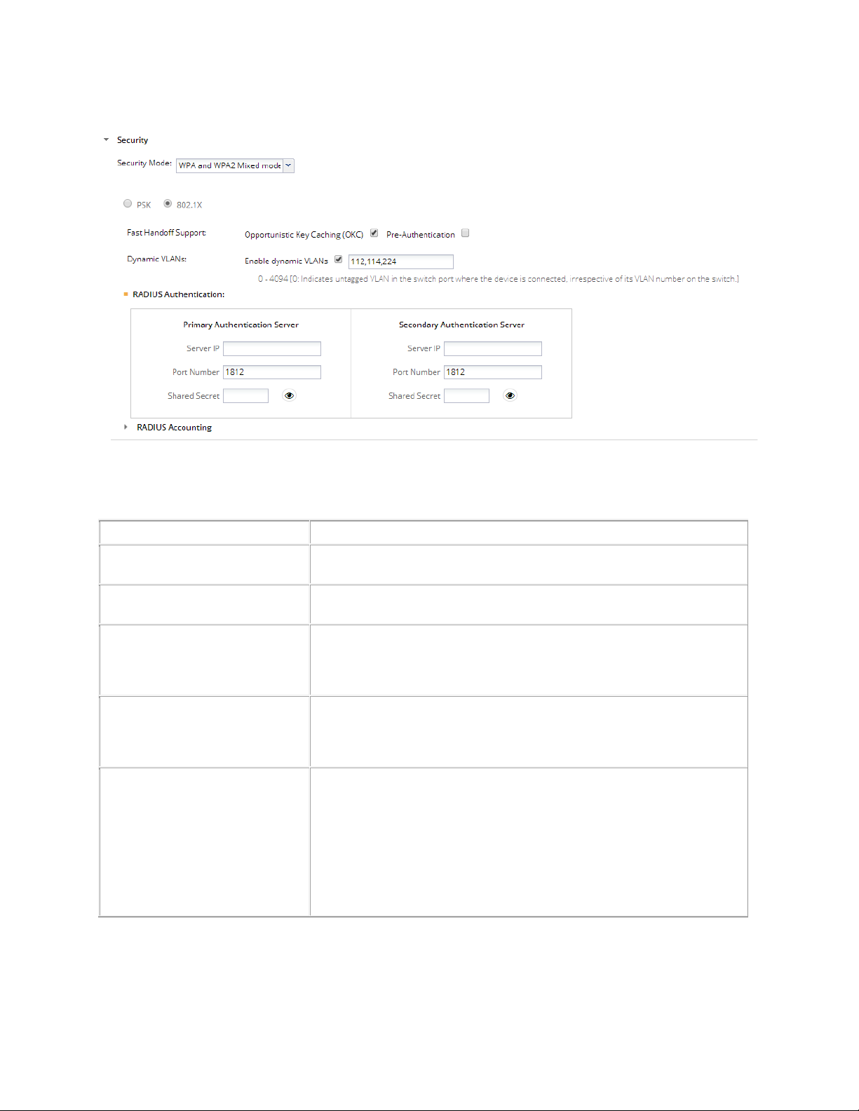
AirTight Management Console User Guide
Field
Description
Profile Name
This field specifies the name of the
SSID
This field specifies the SSID of the wireless profile. This is a
mandatory field.
Broadcast SSID
for this Virtual AP, in the beacon frames. If selected, the beacon for
this Virtual AP carries the SSID.
Client Isolation
This check box indicates whether communication between 2 wireless
clients of this virtual AP is enabled or disabled. If selected, wireless
client communication
Enable P2P
Select this check box to enable to P2P cross connection bit. When a
client
an infrastructure network it is possible to bridge these two networks.
When you enable the P2P cro
network and the infrastructure network can be bridged by the client.
Otherwise, the AP instructs the client not to cross
infrastructure network to the
Wi
network. The P2P cross connection is disabled, by default.
The following image illustrates security settings.
The following table explains the fields present on the Add/Edit Wi-Fi profile and in the Security
Settings. Click Security Settings to view fields under Security Settings.
profile.
This check box indicates whether the SSID is to be broadcast or not
is disabled for the virtual AP.
is connected to a Wi-Fi direct network and to an AirTight AP in
ss connection bit, the Wi-Fi Direct
Cross Connection
-connect the
-Fi Direct network, thus enhancing the security of the wireless
46
Page 58

AirTight Management Console Conf ig ur ati on
Limit number of associations
This field specifies the maximum number of clients that can associate
with the AP. You can select the check box and then specify the
number of clients.
Security Mode
This specifies the security mode applied to the virtual AP.
The possible values are Open, WEP, WPA, WPA2, WPA and WPA2
mixed mode.
Fields related to security mode WEP
Authentication Type
Select
authentication, the key is used for encryption only.
Select
shared key authentication, the same key is used for both encryption
and authent
WEP Type
Select WEP40 if 40-bit WEP security is used.
Select WEP104 if 104-bit WEP security is used.
Key Type
Select
want to enter WEP key in that format. The Sensor/AP combo
converts it to hexadecimal internally.
Select
and want to enter WEP key in that format.
Key
WEP key is a sequence of hexadecimal digits.
If WEP Type is WEP40, enter the key as a 5 character ASCII key or a
10 digit hexadecimal key, depending on the Key Type selected by
you.
If WEP Type is WEP104, enter the key as a 13 character ASCII key
or
by you .
Show Key
Select this check box to see the actual key on the screen. If this
check box is cleared, the key is masked.
Fields related to security mode WPA/WPA2/WPA and WPA2 Mixed Mode
PSK
Select the
Pass phrase
Pass Phrase
Specify the shared key of length 8-63 ASCII characters for PSK
authentication
Show Key
Select this check box
this check box is cleared, the key is masked.
802.1x
Select 802.1x option if you want to use a RADIUS server for
authentication. The fields on the
tabs are enabled on selecting this check boxYou can enable dynamic
VLANs after selecting this check box.
Open if the type of authentication is open. In case of open
Shared if the authentication type is shared key. In case of
ication.
ASCII option if you are comfortable with ASCII format and
HEX option if you are comfortable with hexadecimal format
a 26 digit hexadecimal key, depending on the Key Type selected
PSK option if you want to use a personal shared key. The
field is enabled when this option is selected.
to see the actual pass phrase on the screen. If
Authentication and Accounting
47
Page 59

AirTight Management Console User Guide
Opportunistic Key Caching
Select the check box to enable client fast handoffs using opportunistic
key caching method. Note that the key caching works within the same
subnet only and not across subnets.
Pre
Select the
handoffs using the Pre
NAS ID
This field is used when a network access server (NAS) serves as a
single point to access network resources. Generally, a NAS supports
hundreds of simultaneous users. When a RADIUS client connects to
a NAS, the NAS sends access request packets to the RADIUS
server. These packets must contain either the NAS IP address or the
NAS identifier. The NAS ID or the NAS
authenticate RADIUS clients with the RADIUS server.
You can specify a string for the NAS ID. The default value is %m
where
represents the SSID of the WLAN. This corresponds to the NAS
Identifier attribute on the RADIUS server. The attribute ID for the
NAS
Ensure that the NAS ID is not
configured for the RADIUS server in the RADIUS Authentication
section.
Enable dynamic VLANs
Select the check box to enable the AP to accept the VLAN for the
current user from the RADIUS server. When dynamic VLANs are
enabled, BYOD, firewall, portal and NAT features are disabled for the
Wi
When the check box is selected, you can ente
VLANs in the box adjoining this check box. The list of dynamic VLANs
must be a comma
does not return a VLAN ID or returns a VLAN ID that is not in the list
of dynamic VLANs configured in
redirects the user traffic to the default VLAN (that is, the VLAN ID
specified in the Wi-Fi profile network settings).
Fields in the Authentication Tab-Primary RADIUS Server area
Enter the IP Address of the
Enter the port number at which primary RADIUS server listens for
client requests.
Shared Secret
Enter the secret shared between the prim ary RADIUS server and the
AP.
Fields in the
Enter the IP Address of the secondary RADIUS server here.
Enter the port number at which secondary RADIUS server listens for
client requests.
Shared Secret
Enter the secret shared between the secondary RADIUS
the AP.
Field in the
-authentication
Pre-Authentication check box to enable client fast
-Authentication method.
-Identifier is used to
-%s,
%m represents the Ethernet MAC address of the AP and %s
-
-Identifier RADIUS attribute is 32.
the same as the shared secret
-Fi profile.
r a list of dynamic
-separated list of VLAN IDs. If the RADIUS server
Server IP
Port Number
Authentication Tab- Secondary RADIUS Server area
Server IP
Port Number
48
Accounting Tab
the Wi-Fi profile, the AirTight AP
primary RADIUS server here.
server and
Page 60
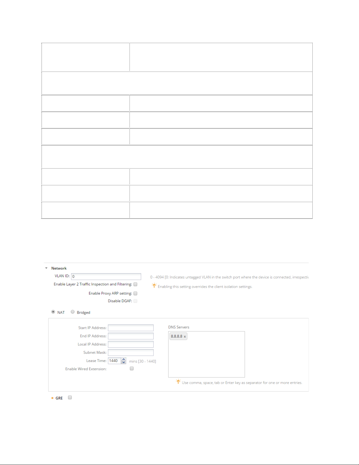
AirTight Management Console Conf ig ur ati on
Enable RADIUS Accounting
Select this check box to enable RADIUS Accounting. The other fields
on the Accounting tab are enabled on selecting this check box. Define
the primary RADIUS Server, and optionally se
Accounting server in the Accounting tab.
Fields in the
Enter the IP Address of the primary accounting server here.
Enter the port number at which primary accounting server listens for
client requests.
Shared Secret
Enter the secret shared between the prim ary accounting server and
the AP.
Fields in the
Enter the IP Address of the secondary accounting
Enter the port number at which secondary accounting server listens
for client requests.
Shared Secret
Enter the secret shared between the secondary accounting server
and the AP.
Accounting Tab- Primary Accounting Server area
Server IP
Port Number
Accounting Tab- Secondary Accounting Server area
Server IP
Port Number
condary RADIUS
server here.
Configure Network Settings for Wi-Fi Profile
Configure the VLAN and DHCP settings, to be used by the SSID profile, using the Network section.
The following image illustrates network settings
Network Settings
49
Page 61

AirTight Management Console User Guide
Field
Description
NAT
Select this check box to enable NAT (network address translation).
Enable NAT if you want to enable wired extension.
Start IP
address
The starting IP address of the DHCP address pool in the selected
network ID.
End IP
address
The end IP address of the DHCP address pool in the selected
network ID.
Local IP
address
An IP address in selected network ID outside of the DHCP address
pool. This address is used as the gateway address for the guest
wireless network.
Subnet Mask
The net mask for the selected network ID.
Lease Time
The DHCP lease time in minutes. Minimum value is 30
minutes,maximum value is 1440 minutes.
DNS Servers
The DNS servers that the wireless clients can make DNS queries to.
You can specify upto 3 DNS servers.
Enable
Extension
Select this check box to extend this wireless LAN to the wired side
using the second Ethernet port present on AirTight device functioning
as an access point.
Field
Description
GRE
Select this check box to enable Generic Routing Encapsulation and to
A bridged network is used when the AP and the clients associating with the AP can be in the same
subnet.
Similarly, network Address Translation (NAT) must be used when you want to have the clients in a
separate subnet and the AP is in a separate subnet. With NAT, the clients can have a private IP address
pool and it is easier to add more clients to the network as they do not require a public IP address.
A wireless LAN, on which NAT is enabled, can be extended to the wired side using the second Ethernet
port present on the Access Point device. Create an isolated wired LAN with one or more wired devices
connected through layer-2 switches and connect the second Ethernet port of the Access Point to this
wired subnet. The wired LAN will be an extension of the wireless LAN of this SSID profile with NAT
enabled. All network settings like NAT and portal, configured on this SSID profile, are also applicable to
the wired devices.
Note: The second Ethernet port is available on some specific AirTight device models only.
When you are configuring NAT parameters, you must specify at least one DNS server. On successful
association, wireless clients will get the specified DNS servers. You can specify up to three such DNS
server IP addresses.
Generic Routing Encapsulation (GRE) is useful when you want to route network traffic from and to a
single end point and apply policies on this end point.
IMPORTANT: GRE works only when NAT is enabled.
To configure network address translation settings, do the following.
Specify the VLAN ID for which the bridging or NAT settings would be applicable.
1.
Select the NAT check box if you want to enable NAT.
2.
Specify the following NAT related settings if you have enabled NAT.
3.
Wired
Select GRE if you want to enable Generic Routing Encapsulation (GRE).
4.
The following table describes the Generic Routing Encapsulation related fields
50
Page 62

AirTight Management Console Conf ig ur ati on
be able to define the GRE related parameters present on this page.
Tunnel IP
Address
IP address of the GRE tunnel interface on the access point. This IP
address should not conflict with any other network setting in the
access point.
Remote
Endpoint IP
Address
IP address of the remote endpoint of the GRE tunnel.
Key
Key in the GRE header. If configured, key should be same at both
ends of the tunnel. Key is not mandatory to be configured in GRE
tunnel.
Exempted
Host/Network
List
List of comma separated network and/or IP addresses that are
exempted from using the GRE tunnel.
Field
Description
NAT
Select this check box to enable NAT (network address translation).
Start IP
address
The starting IP address of the DHCP address pool in the selected
network ID.
End IP
address
The end IP address of the DHCP address pool in the selected
network ID.
Local IP
address
An IP address in selected network ID outside of the DHCP address
wireless network.
Subnet Mask
The net mask for the selected network ID.
Lease Time
The DHCP lease time in minutes. Minimum value is 30
minutes,maximum value is 1440 minutes.
DNS Servers
The DNS servers that the guest clients can make DNS queries to.
Enable Wired
Extension
Select this check box to extend this wireless LAN to the wired side
as an access point.
Field
Description
GRE
Select this check box to enable Generic Routing Encapsulation
and to be able to define the GRE related parameters present on
this page.
Tunnel IP Address
IP address of the GRE tunnel interface on the access point. This
IP address should not conflict with any other network setting in
the access point.
Remote Endpoint
IP address of the remote endpoint of the GRE tunnel.
5. Click Save to save the changes to the network settings.
Edit Network Settings
To edit network address translation settings, do the following.
Specify the VLAN ID for which the NAT settings would be applicable.
1.
Deselect the NAT check box if you want to disable NAT and have a bridged network instead. In case
2.
you want to continue using NAT and only want to edit NAT settings, edit them as required.
pool. This address is used as the gateway address for the guest
using the second Ethernet port present on AirTight device functioning
Select the GRE check box if you want to enable Generic Routing Encapsulation (GRE).
3.
The following table describes the Generic Routing Encapsulation related fields.
51
Page 63

AirTight Management Console User Guide
IP Address
Key
Key in the GRE header. If configured, key should be same at
both ends of the tunnel. Key is not mandatory to be configured in
GRE tunnel.
Exempted
Host/Network List
List of comma separated network and/or IP addresses that are
exempted from using the GRE tunnel.
In case you do not want to use GRE, disable the GRE check box.
Click Save to save the changes to the network settings.
4.
Enable Layer 2 inspection and Filtering
L2 inspection and filtering prevents frames exchanged between two mobile devices from being delivered
by the Wi-Fi access network without first being inspected and filtered in either the hotspot operator
network or the Service Provider core network. Such processing provides some protection for mobile
devices against attack. The inspection and filtering mechanism is out of the scope of the Wi-Fi profile
settings,
If you want to inspect the packets exchanged between two clients in a Wi-Fi network on a wired side host,
do the following.
Select the Enable Layer 2 Traffic Inspection and Filtering check box.
1.
Click Save to save the changes. You can use a packet capture tool to view the packets on the wired
2.
side.
Inspection of layer 2 packets by AirTight AP is not supported.
Disable Downstream Group Addressed Forwarding
The purpose of the Downstream Group Addressed Forwarding (DGAF) Disable feature is to mitigate a
"hole-196” attack. By IEEE 802.11i design, all STAs in a BSS use the same GTK so forgery of groupaddressed frames is always possible. However, in some hotspots multicast service using groupaddressed frames is needed; in these cases, the DGAF Disable bit would be set to 0.
You must enable the proxy ARP setting to disable DGAF.
To disable DGAF and mitigate a hole-196 attack, do the following.
Select the Enable Proxy ARP Setting check box. The Disable DGAF check box is enabled.
1.
Select the Disable DGAF check box to ensure future attacks that exploit the GTK can be mitigated.
2.
Click Save to save the changes.
3.
Enable/Disable DHCP Option 82
DHCP Option 82 is generally used in a distributed DHCP server environment where an AP inserts
additional information to identify the client point of attachment. The circuit ID represents the client point of
attachment. The DHCP Option 82 is available for a bridged SSID only.
When the DHCP option 82 is enabled and the AP receives DHCP packets from the client, a circuit ID is
appended by the AP to the DHCP packets from the client. It then forwards this DHCP request to the
DHCP server. Based on the circuit ID in the DHCP request, the DHCP server makes a decision on the IP
pool from which to assign an IP address to the client. When the DHCP assigns the IP address and
passes it to the AP, the AP passes it on to the client after stripping the circuit ID.
To enable DHCP Option 82 while creating or editing a Wi-Fi profile, do the following.
Under Network Settings, select the Bridged option.
1.
52
Page 64
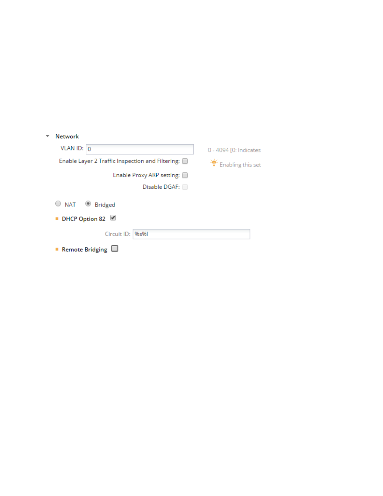
AirTight Management Console Conf ig ur ati on
Select the DHCP Option 82 check box.
2.
Enter the Circuit ID.
3.
You can use special formats %s, %m and %l.
% s is replaced by AP with the SSID.
%m is replaced by AP with the AP MAC address.
%l is replaced by AP with the location tag configured for the location to which the AP is assigned.
The location tag can be configured from Configuration>System Settings>Location Specific Attributes.
Click Save to save the changes.
4.
The following image presents a sample DH CP Option 82 conf ig urat ion in a Wi-Fi profile. Here the circuit
ID is constructed by replacing %s with the SSID and %l with the respective location tag.
The following image illustrates DHCP Option 82 related configuration.
To disable DHCP option 82, do the following.
Under Network Settings for a Wi-Fi profile, deselect the DHCP Option 82 check box.
1.
Click Save to save the changes.
2.
Enable/Disable Remote Bridging
To channelize all wireless traffic to a remote endpoint or gateway through a tunnel, you must enable
remote bridging. The remote endpoint or gateway aggregates wireless frames from different access
points and forwards them to the appropriate network.
You must configure a network interface profile before you enable remote bridging so that you can assign
the network interface profile to the SSID profile. When you enable remote bridging and assign a network
interface profile to the SSID profile, the wireless traffic from the AP is bridged to the remote endpoint
configured in the network interface profile. The traffic is rerouted to the appropriate network from this
remote endpoint.
When you disable remote bridging, the AP stops diverting the wireless traffic to the remote endpoint
configured in the network interface profile that was selected when remote bridging was enabled.
Remote bridging does not work with NAT.
To enable remote bridging, do the following.
Under Network Settings for a Wi-Fi profile, select the Bridged option.
1.
Select the Remote Bridging check box.
2.
Select a network interface profile from the Network Interface Profile.drop-down box.
3.
53
Page 65
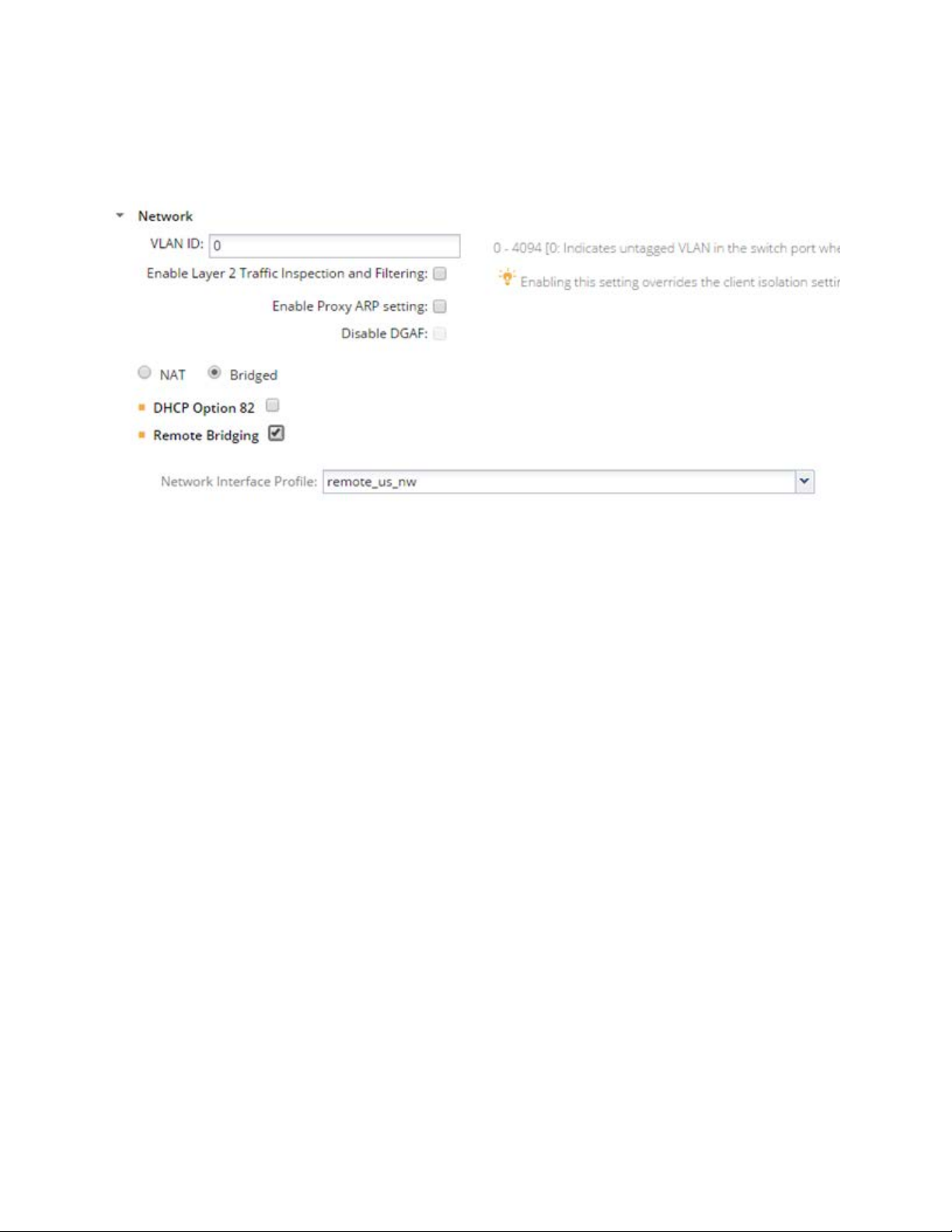
AirTight Management Console User Guide
Click Save to save the changes.
4.
The figure below shows the remote bridging enabled and wireless traffic being diverted to a network
interface profile by the name ‘remote_us_nw’.
To disable remote bridging, do the following.
Under Network Settings for a Wi-Fi profile, deselect the Remote Bridging check box.
1.
Click Save to save the changes.
2.
Captive Portal Setting s
A captive portal is a web page that a client on the network is directed to when the client wants to access
the Internet.
The client is authenticated on this page and is able to access the Internet after successful authentication.
A wireless profile can be configured to serve as a guest network to provide restricted wireless connectivity
(e.g., Internet only) to guest wireless clients. Multiple such guest networks are supported in AirTight Wi-Fi.
Supported Captive Portal Types
The following three types of captive portals are supported in AirTight Wi-Fi or AirTight WIPS.
AP hosted splash page with click through
1.
External splash page for sign-in or click through
2.
External splash page with RADIUS authentication
3.
These are explained in detail below.
AP hosted splash page with click through: A ‘click-through’ splash page is a splash page where
1.
authentication is not supported. The portal pages are hosted and served by the AP. The portal page can
be used to display the terms and conditions of accessing the guest network as well as any other
information as needed.
Steps involved in this type of access are as follows.
54
Page 66
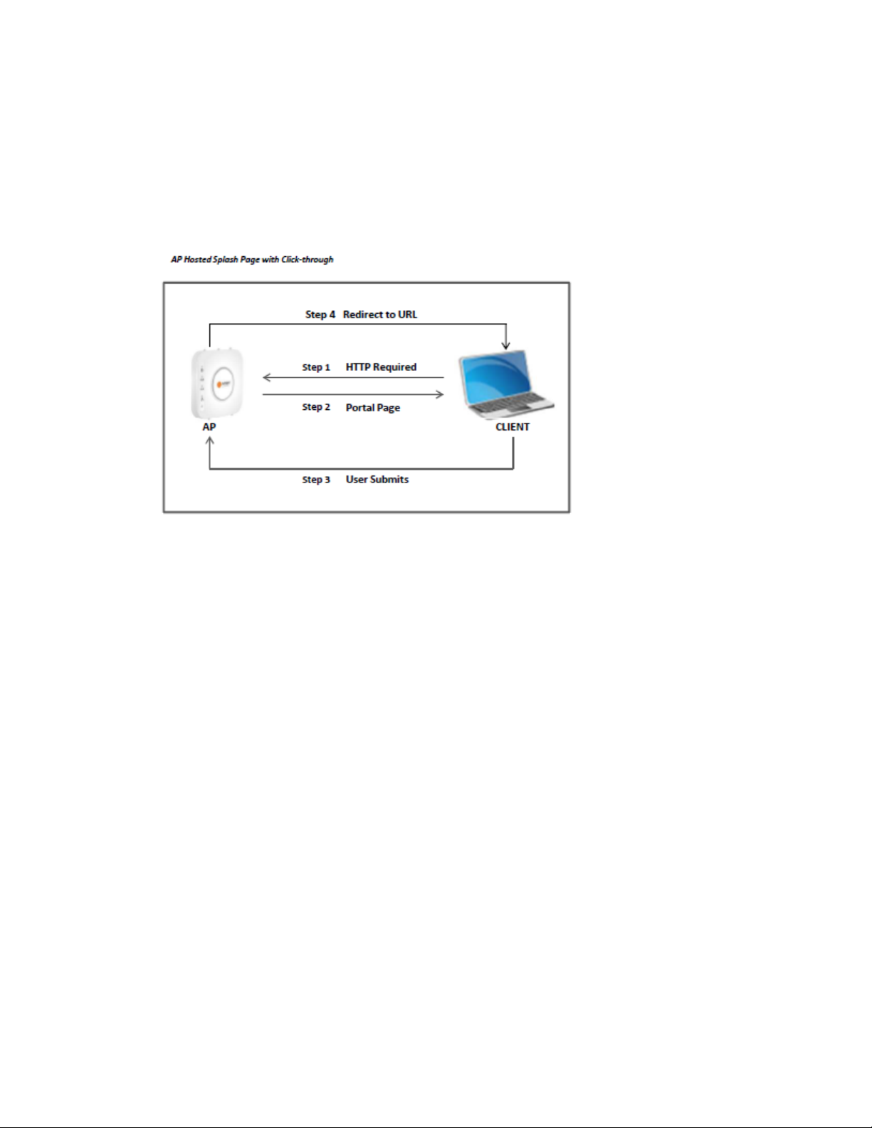
AirTight Management Console Conf ig ur ati on
(a) Wi-Fi user connects to the guest SSID and opens a URL from any web browser using the HTTP
protocol.
(b) AirTight AP intercepts this request and throws a portal page hosted on AP to guest user.
(c) Guest user will accept terms and condition and submits on portal page.
(d) AP will open gate for the client and client will be redirected to redirect URL (if any) or original
requested URL.
Following is a pictorial representation of AP hosted splash page with click through.
External Splash Page for Sign-In/Click-through: The portal is hosted on an external server.
2.
The portal is either click-through without any authentication or has its own authentication mechanism
in place.
Steps involved in this type of access are as follows.
(a) Wi-Fi user connects to the guest SSID and opens a URL from any web browser using the HTTP
protocol.
(b) AirTight AP intercepts this request and redirects the browser to the configured external portal
page along with the request parameters as the GET parameters of the redirected URL.
(c) Portal will authenticate guest user by prompting sign-in or click-through splash page on wireless
user.
(d) After authentication, portal will redirect client to AP with success or failure reply. If AP and portal is
configured with shared secret. Portal will send validation code using which AP wi ll validate r eply
from Portal. Using shared secret between AP and portal would avoid fake user to get access using
spoofing attack.
(e) After successful validation AP will open gate for the client and client will be redirected to redirect
URL (if any) or original requested URL.
Following is a pictorial representation of External splash page for Sign-in/click-through
55
Page 67
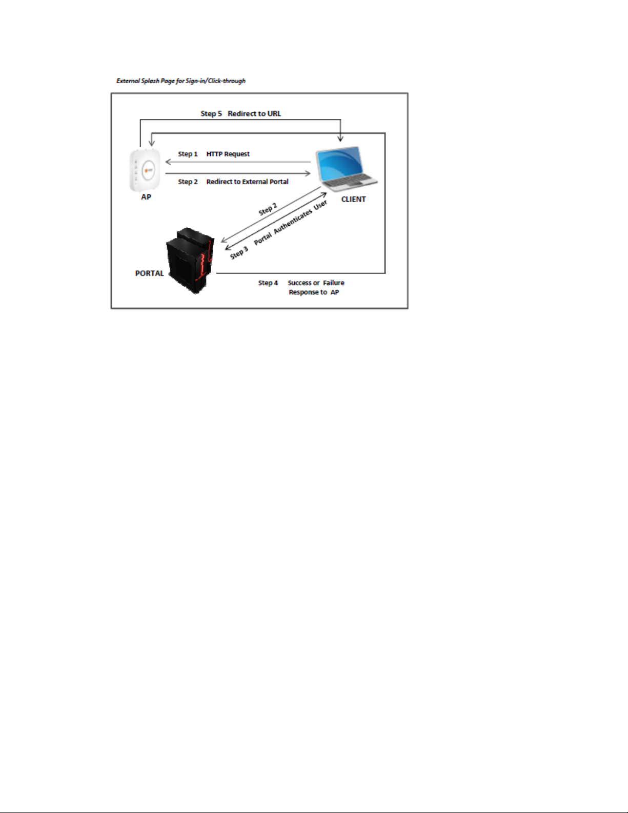
AirTight Management Console User Guide
External Splash Page with RADIUS Authentication: The guest user is redirected to a portal
3.
hosted on an external server. The guest user is authenticated by a RADIUS server, when he logs in
to the external portal.
Steps involved in this type of access are as follows
(a) Wi-Fi user connects to the guest SSID and opens a URL from any web browser using the HTTP
protocol
(b) AirTight AP intercepts this request and redirects the browser to the configured external portal
page along with the request parameters as the GET parameters of the redirected URL.
(c) Portal will prompt the user with the splash page to enter username and password.
(d) User will submit username and password.
(e) Portal will redirect guest user to AP with username and encoded password using shared secret.
(f) Airtight AP will authenticate guest user by RADIUS server using username and decoded
password.
(g) RADIUS server will reply with Access Accept or Reject message for guest user.
(h) Airtight AP will open the Internet access for the client and redirect client to Redirect URL (if any) or
original requested URL.
Following is a pictorial representation of External splash page with RADIUS authentication.
56
Page 68
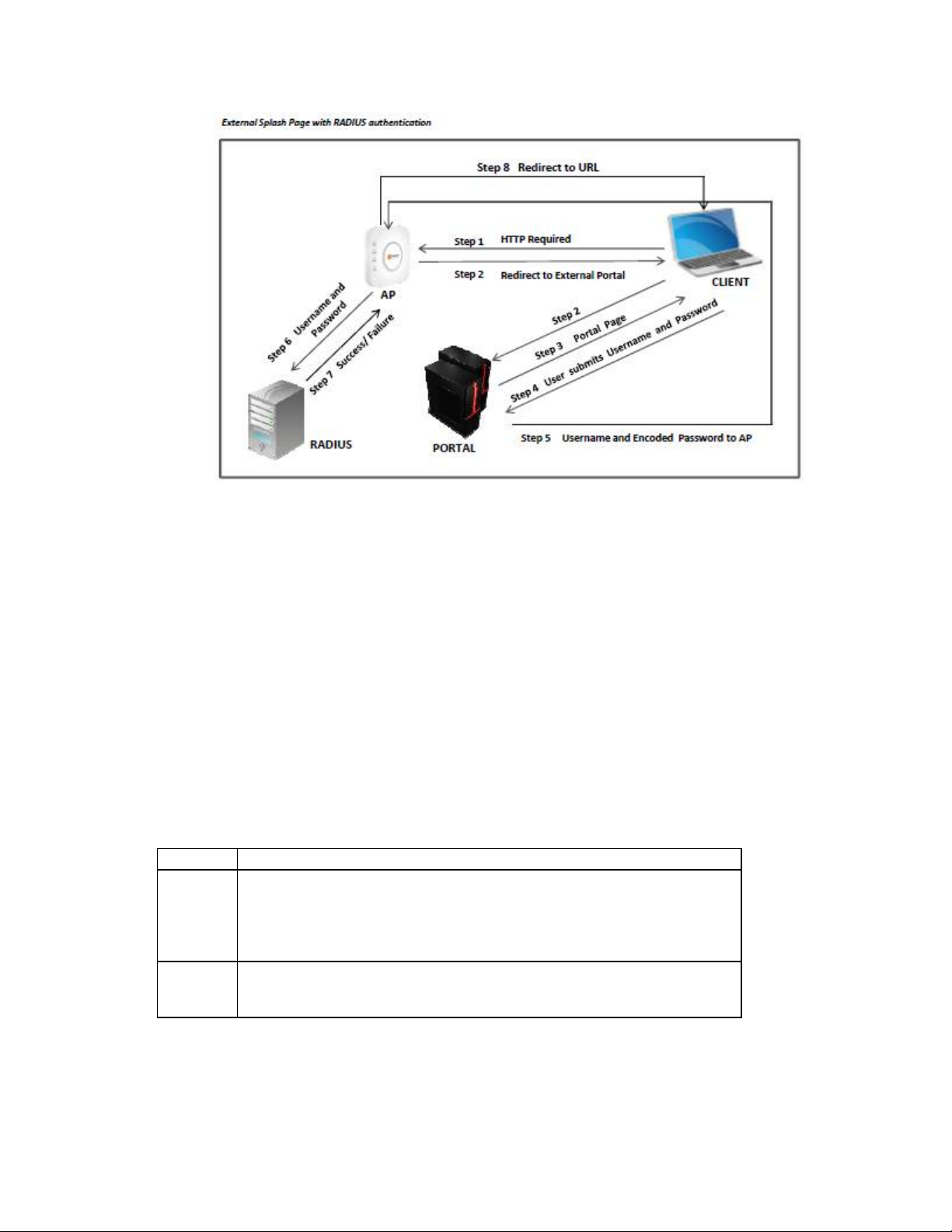
Set up Walled Garden
Field
Description
domain name, sub domain name, host name, subnet or IP address to
www.facebook.com,192.168.121.0/24.
port number.
here. For example, 20-22, 81, 443.
AirTight Management Console Conf ig ur ati on
A walled garden is a method to provide restricted access to the Internet. Walled garden destination(s) can
be accessed at the specified port numbers without displaying the splash page. Domain (e.g. domain.com)
also covers its subdomains (e.g. subdomain.domain.com).
Configure a list of exempted domains, subdomains, IP address ranges and port numbers. (E.g.
192.168.1.0/24) . Services on these IP addresses can be accessed without redirection to the portal
page. If some part of the portal page (e.g., images) is placed on a web server, the web server’s IP
address must be included in this list for the content to be successfully disp layed.
If the mode of authentication is External Splash page for Sign-in/Click-through, you can restrict access to
walled garden destinations unless the guest user accepts the terms and conditions specified on the
splash page.
Do the following to set up a walled garden.
Click Add. The Add Destination dialog opens.
1.
Enter the details.
2.
which the rule applies.
Destination
You can provide a comma-separated list of more than one host names
here. For example, 192.168.8.173,
Port
You can provide a comma-separated list of port numbers or port ranges
To delete an exempted destination, select the entr y and clic k Remove.
3.
Configure Captive Portal Settings
57
Page 69
AirTight Management Console User Guide
To configure captive portal settings, do the following.
Select the Enable Captive Portal check box to display a portal page to be shown to the client on
1.
using the guest network.
Select the mode of access to the Internet through the captive portal. Do one of the following:
2.
(a) Select the AP Hosted Splash Page with click through option. You must create a .zip file of the
portal page along with any other files like images, style sheets etc and upload this file. The zip file
must satisfy the following requirements for the portal to work correctly.
a. The zip file should have a file with the name “index.html” at the root level (i.e., outside of
any other folder). This is the main portal page. It can have other files and folders, (and
folder within folders) at the root level that are referenced by the index.html file.
b. The total unzipped size of the files in the bundle should be less than 100 KB. In case,
large images or other content is to be displayed on the page, this content can be placed
on an external web server with references from the index.html file. In this case, the IP
address of the external web server must be included in the list of exempt hosts (see
below).
c. The index.html file must contain the following HTML tags for the portal to work correctly:
• A form element with the exact starting tag: <form method="POST"
action="$action">
• A submit button inside the above form element with the name “mode_login”. For
example: <input type=”image” name=”mode_login” src=”images/login.gif”>The
exact tag: <input type="hidden" name="redirect" value="$redirect"> inside the
above form element.
You can download the factory default portal bundle file and use it as a template to create a
custom portal bundle. Click Download Sample to download the factory default portal bundle
file.
Upload the portal bundle (default or custom). Click Choose File following Upload Bundle to
upload the bundle.
Click Open to upload the portal bundle.
58
Page 70

AirTight Management Console Conf ig ur ati on
Field
Description
Called station ID
a free form text parameter that the AP passes to the RADIUS
server in the standard RADIUS parameter,'Called
dur
%m' can be specified which will be expanded to the Ethernet MAC
address of the AP.
NAS ID
This field is used when a network access server (NAS) serves as a
single point to access network
supports hundreds of simultaneous users. When a RADIUS client
connects to a NAS, the NAS sends access request packets to the
RADIUS server. These packets must contain either the NAS IP
address or the NAS identifier. The NAS ID o
used to authenticate RADIUS clients with the RADIUS server.
You can specify a string for the NAS ID. The default value is %m
%s, where %m represents the Ethernet MAC address of the AP
and %s represents the SSID of the WLAN. This co
NAS
the NAS
Ensure that the NAS ID is not the same as the shared secret
configured for the RADIUS server in the RADIUS Authentication
section.
Primary Authentication server d etails
Server IP
IP address of primary authentication server.
Port Number
port number of primary authentication server listens for client
requests.
Shared Secret
shared secret between the AP and primary authentication server.
Secondary authentication server de tails
Server IP
IP address of secondary authentication server.
Port Number
port number of secondary authentication server listens for client
requests.
Shared Secret
shared secret between the AP and secondary authentication
server.
To restore the portal bundle to factory default file, click Restore Default.
(b) Select the External Splash Page for Sign-in/Click-through option. Specify Splash Page URL,
using which wireless user will be redirected to external portal. This portal will prompt wireless
user to enter username and password. You must select the check box for the shared secret, if
applicable, and specify the shared secret for SSID-external portal communication.
If you want the guest user to accept the terms and conditions on the splash page before being
able to access walled garden destinations, select the Restrict access to Walled Garden check
box. If this check box is not selected, the guest user is abl e to acces s the walled g arden
destinations without accepting the terms and conditions on the splash page.
(c) Select External Splash Page with RADIUS Authentication.
In this case, you also need to specify the following fields
Splash Page URL, us in g which w irel ess user will be redir ected to exter na l portal . You m us t enter a
shared secret for SSID-external portal communication. Click RADIUS settings hyperlink to configure
RADIUS server settings, using which the AP will actually authenticate the wireless user.
Specify the primary and optionall y, second ary authentication server details.
-Station-Id ',
ing the authentication process. The special format specifier '
-Identifier attribute on the RADIUS server. The attribute ID for
-Identifier RADIUS attribute is 32.
If you want RADIUS accounting to be enabled, select the accounting check box and specify the
accounting details, using whic h AP will act ua ll y authen tic ate wire les s user. InRADIUS Server
Settings specifyServer IPandPorton whichRADIUS server is running.
resources. Generally, a NAS
r the NAS-Identifier is
-
rresponds to the
59
Page 71

AirTight Management Console User Guide
Field
Description
Interval
Accounting interval, in minutes. Minimum interval can be 1 minute,
and maximum interval can be 60 minutes.
Primary accounting server details
Server IP
IP address of primary accounting server
Port
Port number of primary accounting server listens for client
requests.
Shared Secret
Shared secret between the AP and primary accounting server.
Secondary accounting server detai ls
Server IP
IP address of secondary accounting server.
Port Number
Port number of secondary accounting server listens for client
requests.
Shared Secret
Shared secret between the AP and secondary accounting server.
Number
Configure the External Portal parameters. Refer to Configure External Portal Parameters below for
3.
details.
4. Select the Roaming check box, if you don't want the Wi-Fi clients to see the splash page when they
roam from one AP to another.
Select the Enable Internet Connectivity Detection check box, if you want to check the internet
5.
connectivity and display a portal error page in case of loss of Internet connectivity.
The 'Enable Internet Connectivity Detection' feature can be used to provide feedback to guests when
Internet is temporarily unavailable on the guest SSID. When the access point detects that Internet
connectivity is not available from the guest VLAN, it automatically redirects all HTTP requests of the
guest users to a splash page with a message that Internet is temporarily unavailable. When using the
AP Hosted Splash Page for Click-through option, a customized splash page included in the bundle
with the name “NoInternet.html” is displayed when Internet is down. If this page is not included in the
bundle or if external splash page options have been configured, the AP displays a factory default
splash page when internet is down.
Note that when Internet is down, guest users will not be able to access local HTTP services as well if
the Enable Internet Connectivity Detection feature is enabled.
The Enable Internet Connectivity Detectio n feature will not work for a SSID profile configured with
GRE.
Specify Login Timeout, in minutes, for which a wireless user can access the guest network after
6.
submitting the portal page.
After the timeout, access to guest network is stopped and the portal page is displayed again. The
user has to submit the portal page to regain access to the guest network. If the user disconnects and
reconnects to the guest network before his session times out, he does not have to enter his
credentials on the splash page. If you are using AirT ig ht Guest Man ager and you have spec if ied a
login timeout in AirTight Guest Manager, this login timeout overrides the Login Timeout setting in the
SSID profile.
Specify Blackout Time, in minutes. This is the time for which a user is not allowed to login after his
7.
previous successful session was timed out.
For example, if the session time-out is 1 hour and the blackout time is 30 mins, a user will be timed
out one hour after a successful login. Now after this point, the user will not be able to login again for
30 minutes. At the end of 30 minutes, the user can login again.
Specify the Redirect URL. The browser is redirected to this URL after the user clicks the submit
8.
button on the portal page.
If left empty, the browser is redirected to the original URL accessed from the browser for which the
portal page was displayed.
Specify the value of the Service Identifier that you have defined in Advanced Parameters. This is a
9.
free form parameter that can be passed to the external portal.
60
Page 72

AirTight Management Console Conf ig ur ati on
Request
Attributes
Description
Request Type
field name for request type field.
Challenge
field name for random text used for authentication.
Client MAC
field name for the MAC address of the client.
AP MAC Address
field name for MAC address of the access point that is
communicating with the external portal.
AP IP Address
field name for the IP address of the access point that is
communicating with the external portal. This should match the
field name used by the external portal.
AP Port Number
field name for the AP port number on which the AP and external
server communicate.
Failure Count
field name for the count of the number of failed login attempts.
Requested URL
field name for the requested URL that is the URL requested by the
client through the AP, to the external server.
Login URL
field name for the login URL.
Logoff URL
field name for the logoff URL.
Remaining Blackout
Time
field name for the remaining blackout time.
Service Idenitifier
name of the portal parameter that is used to pass the service
identifier value to the external portal. The service identifier value is
specified in the Captive Portal section of the SSID Profile. This
parameter can be used by the external portal to implement SSID
profile specific functionality like different portals for different SSIDs
etc.
Response
Attributes
Description
Challenge
field name for the challenge
Response Type
field name for the response type.
Challenge Response
field name for the challenge response.
Redirect URL
field name for the redirect URL
Login Timeout
field name for login timeout.
This parameter can be used by the external portal to implement SSID profile specific functionality. For
example, each SSID can have a separate portal page.
Click Save to save the settings.
10.
Configure External Portal Parame ters
You must configure the external portal parameters if you want to redirect users to a portal page hosted on
an external server.
All request and response attributes that are marked with an asterisk are mandatory. The request
parameters/attributes are sent from the AP to the external portal. The response parameters are sent from
the external portal to the AP. These parameters are used in the name - value pairs in the redirection URL.
The following table explains the request and response attributes in detail.
61
Page 73

AirTight Management Console User Guide
User name
field name for user name.
Password
field name for password.
Note: The individual field names used by the AP should match the corresponding field
names used by the external server hosting the portal.
not be able to communicate if the name of the same parameter is different on either si
The fields in
Wi-Fi / AirTight WIPS side.
The AP and the external server may
de.
External Portal Parameters facilitate the field name change on the AirTight
Edit Captive Portal Settings
To edit captive portal settings, do the following.
Select the Enable Captive Portal check box to display a portal page to be shown to the client on
1.
using the guest network.
Select the mode of access to the Internet through the captive portal. Do one of the following:
2.
(a) Select the AP Hosted Splash Page with click through option. You must create a .zip file of the
portal page along with any other files like images, style sheets etc and upload this file. The zip file
must satisfy the following requirements for the portal to work correctly.
a. The zip file should have a file with the name “index.html” at the root level (i.e., outside of
any other folder). This is the main portal page. It can have other files and folders, (and
folder within folders) at the root level that are referenced by the index.html file.
b. The total unzipped size of the files in the bundle should be less than 100 KB. In case,
large images or other content is to be displayed on the page, this content can be placed
on an external web server with references from the index.html file. In this case, the IP
address of the external web server must be included in the list of exempt hosts (see
below).
c. The index.html file must contain the following HTML tags for the portal to work correctly:
• A form element with the exact starting tag: <form method="POST"
action="$action">
• A submit button inside the above form element with the name “mode_login”. For
example: <input type=”image” name=”mode_login” src=”images/login.gif”>The
exact tag: <input type="hidden" name="redirect" value="$redirect"> inside the
above form element.
You can download the factory default portal bundle file and use it as a template to create a
custom portal bundle. Click Download Sample to download the factory default portal bundle
file.
Upload the portal bundle (default or custom). Click Choose File following Upload Bundle to
upload the bundle.
62
Page 74
AirTight Management Console Conf ig ur ati on
Field
Description
Called station id
a free form text parameter that the AP passes to the RADIUS
server in the standard RADIUS parameter,'Called
during the authentication process. The special format specifier '
%m' can be specified which will be
address of the AP.
Primary Authentication server d etails
Server IP
IP address of primary authentication server.
Port Number
port number of primary authentication server listens for client
requests.
Shared Secret
shared secret between the AP and primary authentication server.
Click Open to upload the portal bundle.
To restore the portal bundle to factory default file, click Restore Default.
(b) Select the External Splash Page for Sign-in/Click-through option. Specify Splash Page URL,
using which wireless user will be redirected to external portal. This portal will prompt wireless
user to enter username and password. You must select the check box for the shared secret, if
applicable, and specify the shared secret for SSID-external portal communication.
(c) Select External Splash Page with RADIUS Authentication.
In this case, you also need to specify the following fields
Splash Page URL, using which wireless user will be redirected to external portal. You must enter
a shared secret for SSID-external portal communication. Click RADIUS settings hyperlink to
configure RADIUS server settings, using which the AP will actually authenticate the wireless
user.
Specify the primary and optionall y, second ary authentication server details.
-Station-Id ',
expanded to the Ethernet MAC
63
Page 75

AirTight Management Console User Guide
Secondary authentication server de tails
Server IP
IP address of secondary authentication server.
Port Number
port number of secondary authentication server listens for client
requests.
Shared
shared secret between the AP and secondary authentication
server.
Field
Description
Interval
accounting interval, in minutes. Minimum interval can be 1 minute,
and maximum interval can be 60 minutes.
Primary accounting server details
Server IP
IP address of primary accounting server.
Port Number
port number of primary accounting server listens for client
requests.
Shared Secret
shared secret between the AP and primary accounting server.
Secondary accounting server detai ls
Server IP
IP address of secondary accounting server.
Port Number
port number of secondary accounting server listens for client
requests.
Shared Secret
shared secret between the AP and secondary accounting server.
Secret
If you want RADIUS accounting to be enabled, select the accounting check box and specify the
accounting details, using whic h AP will act ua ll y authen tic ate wire les s user. In RADIUS Server
Settings specify Server IP and Port on whichRADIUS server is running.
Configure the External Portal parameters. Refer to Configure External Portal Parameters below for
3.
details.
4. Select the Roaming check box, if you don't want the Wi-Fi clients to see the splash page when they
roam from one AP to another.
Select the Enable Internet Connectivity Detection check box, if you want to check the internet
5.
connectivity and display a portal error page in case of loss of Internet connectivity.
The 'Enable Internet Connectivity Detection' feature can be used to provide feedback to guests when
Internet is temporarily unavailable on the guest SSID. When the access point detects that Internet
connectivity is not available from the guest VLAN, it automatically redirects all HTTP requests of the
guest users to a splash page with a message that Internet is temporarily unavailable. When using the
AP Hosted Splash Page for Click-through option, a customized splash page included in the bundle
with the name “NoInternet.html” is displayed when Internet is down. If this page is not included in the
bundle or if external splash page options have been configured, the AP displays a factory default
splash page when internet is down.
Note that when Internet is down, guest users will not be able to access local HTTP services as well if
the Enable Internet Connectivity Detection feature is enabled.
The Enable Internet Connectivity Detectio n feature will not work for a SSID profile configured with
GRE.
Specify Login Timeout, in minutes, for which a wireless user can access the guest network after
6.
submitting the portal page.
After the timeout, access to guest network is stopped and the portal page is displayed again. The
user has to submit the portal page to regain access to the guest network. If the user disconnects and
reconnects to the guest network before his session times out, he does not have to enter his
credentials on the splash page. If you are using AirT ig ht Guest Man ager and you have spec if ied a
login timeout in AirTight Guest Manager, this login timeout overrides the Login Timeout setting in the
SSID profile.
64
Page 76

AirTight Management Console Conf ig ur ati on
Field
Description
Rule
Name
domain name, sub domain name, host name, subnet or IP address to
You can provide a comma-separated list of more than one host names
Specify Blackout Time, in minutes. This is the time for which a user is not allowed to login after his
7.
previous successful session was timed out.
For example, if the session time-out is 1 hour and the blackout time is 30 mins, a user will be timed
out one hour after a successful login. Now after this point, the user will not be able to login again for
30 minutes. At the end of 30 minutes, the user can login again.
Specify the Redirect URL. The browser is redirected to this URL after the user clicks the submit
8.
button on the portal page.
If left empty, the browser is redirected to the original URL accessed from the browser for which the
portal page was displayed.
Specify the value of the Service Identifier that you have defined in Advanced Parameters. This is a
9.
free form parameter that can be passed to the external portal.
This parameter can be used by the external portal to implement SSID profile specific functionality. For
example, each SSID can have a separate portal page.
Click Save to save the settings.
10.
Disable Captive Portal
Deselect the Enable Captive Portal check box to disable captive portal settings.
Firewall Settings
A firewall controls the incoming and outgoing network traffic, based on a set of defined rules. Click
Firewall on the Add SSID Profile page to configure firewall settings for the SSID profile. You can add,
modify, reorder, and delete firewall rules from the Firewall section.
The firewall rules defined for the SSID profile are evaluated in a top down manner. That is,the first rule is
evaluated first, followed by the next rule, and so on, till a match is found for the respective host name and
direction.
When you create a SSID profile, you will notice that the default rule has been set to block all incoming
and outgoing requests from any host or domain. Define the default rule by selecting Allow or Block to
allow or block any type of requests from IP addresses, host names, subdomain names or domain names
for which no specific firewall rules have been defined.
To enable firewall for the SSID profile, select the Enable Firewall check box. If it has been previously
selected and you want to disable firewall for the SSID profile, deselect the Enable Firewall check box.
Add New Firewall Rule
Do the following to add a firewall rule.
Click Add New Rule.
1.
If one or more rules have already been defined, select Above the selected rule or Below the
2.
selected rule to insert the new rule above or below the selected rule, depending on how you want to
prioritize the rules.
Enter the rule details as specified in the following table.
3.
name of the rule
Host
which the rule applies.
65
Page 77
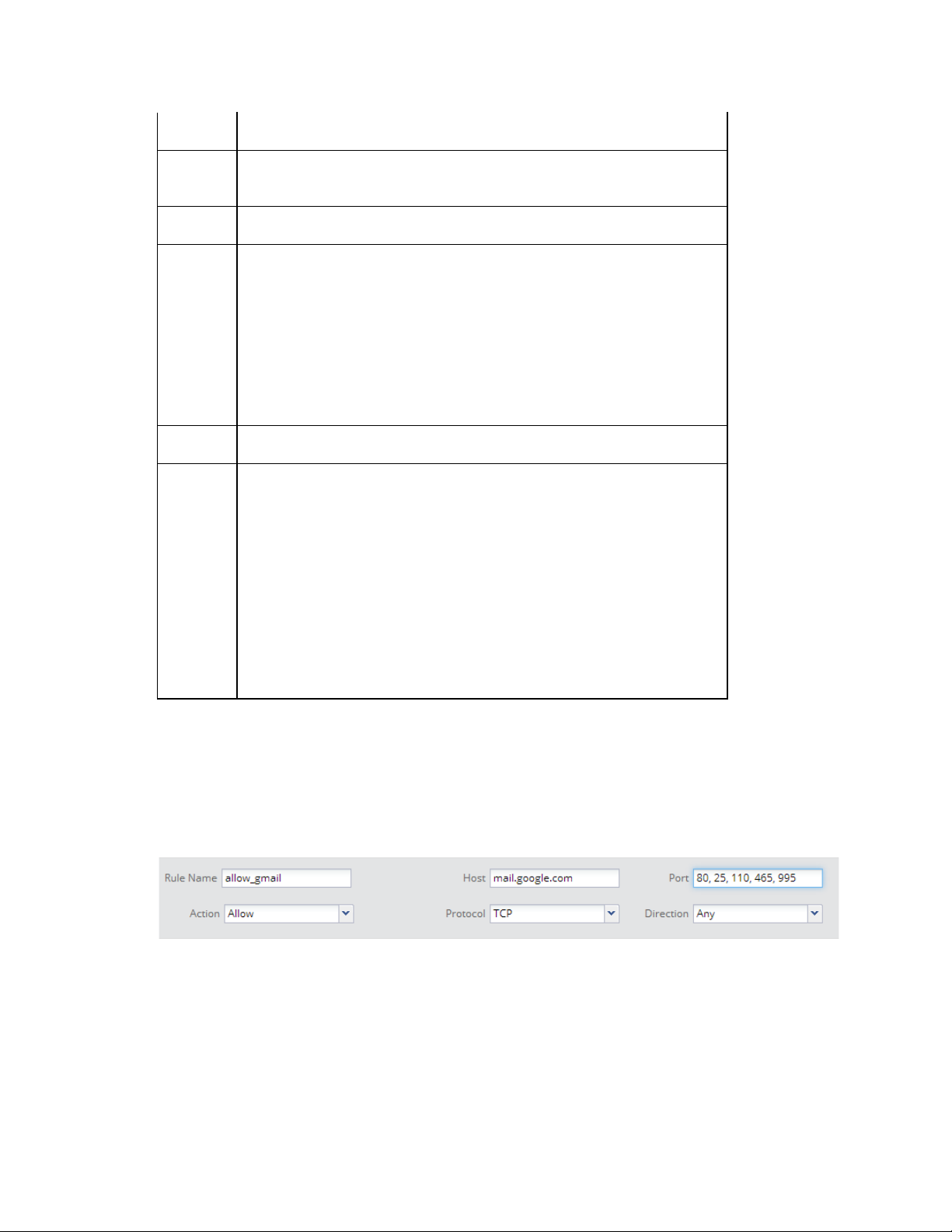
AirTight Management Console User Guide
here. For example, 192.168.8.173,
www.facebook.com,192.168.121.0/24.
port number.
ranges here. For example, 20-22, 80, 443.
if you want to block the traffic to or from the host option, select block. if
you want to allow traffic to or from the host, select allow.
network protocol. The following options are available.
the Any option.
Protocol
No.
protocol number. This field appears only when the selected protocol is
Other
direction of network traffic. The following options are available.
direction as Incoming.
Port
Action
Protocol
Direction
You can provide a comma-separated list of port numbers or port
TCP: If the rule is for TCP-based communication, select the TCP
option.
UDP: If the rule is for UDP-based communication, select the UDP
option.
Other: If the rule is for a communication based on a protocol other
than TCP and UDP, select Other. You must specify the protocol
number in this case.
Any: If the rule is for communication that is not protocol specific, select
Outgoing: If the rule is to be applied to data going out of your network,
that is, from wireless to wired, then select the Outgoing option.
Incoming: If the rule is to be applied to data coming into your network,
that is, from wired to wireless, select the Incoming option.
Any: If the rule is to be applied to both outgoing and incoming traffic,
select the Any option.
For instance, if you want to allow or prevent users of your wireles s
network from accessing certain websites or domains, you can define
the respective rule with direction as Outgoing. Similarly, if you want
prevent certain hosts from accessing your wireless network, you can
define the rule specific to this host name or domain name with
For example, if you want to allow all incoming and outgoing TCP requests from and to the host
'mail.google.com', ports 80, 25, 110, 465, 995, you will specify the rule details as follows.
Click Add New Rule to add the rule.
Specify an appropriate name for the rule in Rule Name.
Specify Host Name as 'mail.google.com, Port as 80, 25,110, 465, 995 Action as Allow, Protocol
as TCP, Direction as Any. See the image below for the rule.
Firewall Rule
Click Save to save the rule.
4.
Reorder Firewall Rules
If you have more than 1 firewall rules defined, you can reorder them.
Do the following to reorder the rules.
66
Page 78

AirTight Management Console Conf ig ur ati on
Field
Description
Rule
Name
domain name, sub domain name, hostname or IP address to which the rule
here. For example, 192.168.8.173, www.facebook.com, 192.168.121.0/24.
port number.
here. For example, 20-22, 80, 443.
if you want to block the traffic to or from the host option, select block. if you
want to allow traffic to or from the host, select the allow option.
network protocol. The following options are available.
Any option.
Protocol
No.
protocol number. This field appears only when the selected protocol is
'other'
direction of network traffic. The following options are available.
this host name or domain name with direction as Incoming.
Click the rule to move.
1.
Hold the mouse down and drag the rule to the desired position, for instance between 2 other rules.
2.
Release the mouse. The rule is placed at the new position.
3.
Click Save to save the rule reordering.
4.
Edit Firewall Rule
Do the following to add a firewall rule.
Click the radio button for the rule to edit.
1.
Edit the rule details as specified in the following table.
2.
name of the rule
Host
Port
Action
Protocol
Direction
applies.
You can provide a comma-separated list of more than one host names
You can provide a comma-separated list of port numbers or port ranges
TCP: If the rule is for TCP-based communication, select the TCP option.
UDP: If the rule is for UDP-based communication, select the UDP option.
Other: If the rule is for a communication based on a protocol other than
TCP and UDP, select Other. You must specify the protocol number in this
case.
Any: If the rule is for communication that is not protocol specific, select the
Outgoing: If the rule is to be applied to data going out of your network, that
is, from wireless to wired, then select the Outgoing option.
Incoming: If the rule is to be applied to data coming into your network, that
is, from wired to wireless, select the Incoming option.
Any: If the rule is to be applied to both outgoing and incoming traffic, select
the Any option.
For instance, if you want to allow or prevent users of your wireless network
from accessing certain websites or domains, you can define the respective
rule with direction as Outgoing. Similarly, if you want prevent certa in host s
from accessing your wireless network, you can define the rule specific to
Delete Firewall Rule
Do the following to delete a rule.
Click the Delete hyperlink for a rule to delete the rule.
1.
Click Yes on the message that appears, to confirm the delete operation. To cancel the delete
2.
operation click No.
67
Page 79

AirTight Management Console User Guide
Click Save to save changes to the set of firewall rules.
3.
Traffic Shaping & QoS
Effective utilization of network bandwidth can be achieved in various ways.
Some of the ways in which you can do this is by setting an upload and download limit for the network,
restricting the number of client association, band steering and defining QoS parameters. You can opt for
one or more of these ways depending on the network traffic, the applications used on the SSID, and the
AirTight device model in use.
Band Steering
When an SSID is configured in both 2.4 GHz and 5 GHz bands, clients that are capable of both bands
(b/g/n and a/n) and are operating in one of the bands, can be steered towards the other band to balance
the load on the AirTight AP.
This load balancing feature is called band steering. It is available in dual-radio access point models.
It helps in evenly distributing the Wi-Fi clients between the two bands.
Band steering works in a bi-directional manner, steering clients from 2.4 GHz to 5 GHz radio or from 5
GHz to 2.4 GHz radio, to balance the load on the AirTight AP.
Clients connecting to an AP will be steered from 2.4 GHz to 5 GHz or 5 GHz to 2.4 GHz when all the
following conditions are satisfied.
Band steering is enabled on the SSID profile that the client is associated with.
•
Client RSSI is equal to and above the RSSI threshold mentioned in Traffic Shaping and QoS
•
settings for SSID profile.
The number of clients on one radio are not more than clients on the other radio plus the Spectrum
•
Load Balancing threshold defined in the device template (under Radio Advanced Settings) applied
to the AP, counted among all SSIDs associated with the AP.
When you enable band steering, you need to specify the RSSI threshold of the clients. This is required
due to the fact that clients with weak signal strength cannot operate effectively in the 5 GHz band and
hence should not be steered even if they are capable of operating in 5 GHz.
To configure band steering, do the following.
Select the Enable Band Steering check box.
1.
Specify the RSSI Threshold of the client.
2.
Click Save to save the changes.
3.
Traffic shaping
You can limit the upload and/or download bandwidth on an SSID.
To restrict the upload bandwidth on the SSID, do the following.
Select Restrict upload bandwidth on this SSID to check box and enter a data rate, from 0 through
1.
1024 Kbps, to restrict the upload bandwidth for the SSID to the value specified here.
Click Save to save the changes.
2.
To restrict the download bandwidth on the SSID, do the following.
Select Restrict download bandwidth on this SSID to check box and enter a data rate, from 0
1.
through 1024 Kbps, to restrict the download bandwidth for the SSID to the value specified here.
Click Save to save the changes.
2.
68
Page 80

AirTight Management Console Conf ig ur ati on
AirTight attribute
RADIUS attribute ID
AirTight Per User Download Limit
5
Large enterprises, sometimes, use RADIUS attributes to propagate network policies across multiple
points of access. Users are divided into groups, and policies are applied to each group to effectively
control access to network resources. Each user group is assigned an upload bandwidth and a download
bandwidth, based on the need of that user group. For instance, the Sales user group would be assigned
upload and download bandwidths that differ from the upload and download bandwidths assigned to the
HR user group.
In case of clients authenticated using a RADIUS server, you can configure the AirTight AP to retrieve and
use the bandwidth control settings defined by the RADIUS server. The unit for bandwidth is Kbps.
Based on the values returned by the RADIUS server, the AirTight AP dynamically sets the upload and
download bandwidths for the RADIUS-authenticated user. If the RADIUS server does not return a value
for the bandwidths, the default upload and download bandwidth defined in the Traffic Shaping and QoS
settings are used. If a user has more than one devices, the bandwidth limit is applied separately on each
of these devices. This means that if a user uses 2 devices, and the bandwidth for the user or the user
group is 4 Mbps, 4 Mbps is the bandwidth limit applied to each of these devices.
User-specific bandwidth values can come from one or more of the following.
From portal with external RADIUS authentication server.
•
From GAMS portal.
•
From the RADIUS server, if SSID is configured with 802.1x security.
•
From AirTight server- If no value is returned by either of the above, the default value defined by
•
AirTight server is used.
If bandwidth values are returned by more than one of the above-mentioned sources, the order of
precedence to identify the bandwidth limit to apply is the same as mentioned above. That is, external
RADIUS authentication server has the highest priority followed by GAMS portal, and then RADIUS server
used for 802.1x authentication.
The default AirTight server bandwid th va lue is used only if none of the other sources return a bandwidth
value.
To enable RADIUS-based assignment of bandwidth based on the user group of the RADIUS user, do the
following.
Navigate to Configuration>Device Configuration>SSID Profile.
1.
On the Wi-Fi profile tab, add or edit a Wi-Fi profile.
2.
Click Traffic Shaping & QoS. The section expands.
3.
Select the Enable per User Traffic Control check box. The fields for Restrict user upload
4.
bandwidth to and Restrict client down load bandwidth to appear.
To specify a default bandwidth value for upload bandwidth, select the check box for Restrict user
5.
upload bandwidth to and specify a value between 0 and 1024 Kbps. This is used when no upload
bandwidth is returned by the RADIUS server for the RADIUS user.
To specify a default bandwidth value for download bandwidth, select the check box for Restrict user
6.
download bandwidth to and specify a value between 0 and 1024 Kbps. This is used when no
download bandwidth is returned by the RADIUS server for the RADIUS user.
The RADIUS user attributes used to set per user bandwidth fall under vendor specific attributes-IETF ID
:26. The vendor ID for AirTight is 16901.
The following table shows the mapping of the AirTight attributes with the RADIUS attributes.
69
Page 81

AirTight Management Console User Guide
AirTight Per User Upload Limit
6
Limit Clients associating with the AP
You can limit the number of clients associating with the AP to restrict the network bandwidth.
To limit the number of clients associating with the AP, do the following.
Select the Limit number of associations check box if you want to specify the maximum number of
1.
clients that can associate with the AP.
Specify the maximum number of clients in the field next to the Limit number of associations check
2.
box.
Click Save to save the changes.
3.
Define Minimum Data Rate
You can specify the minimum data rate for the AP-client communication. Data rates greater than the
specified data rate are used to communicate with clients.
To specify a minimum data rate, do the following.
Select the Minimum data rate check box.
1.
Specify the minimum data rate for communication in the field adjacent to the Minimum data rate
2.
check box.
Click Save to save the changes.
3.
Quality of Service (QoS)
The priority of various types of traffic is defined in QoS. QoS stands for quality of service. The service
guarantee is imperative in case of streaming multimedia applications, for example, voice over IP, video,
online games etc. It is necessary to define the priority when the network bandwidth is shared for such
applications. You must define the QoS parameters if you are using the SSID for such applications. QoS
ensures that applications or traffic requiring higher priority gets the required priority. The service
guarantee for the service being provided is met by allocating adequ ate ban d width bas ed on the Qo S
priority.
If you configure the radio in 11N mode, WMM (Wi-Fi multimedia) will alw a ys be enabl ed, bec aus e WMM
is mandatory in 11N mode.
In 11N mode, if the QoS check box is not selected, the system uses the default QoS parameters.
The default QoS settings are as follows.
o SSID priority is voice.
o Priority type is cei lin g .
o Downstream marking is DSCP.
o Upstream marking is enabled and the value is 802.1p marking.
The system uses the user-configured QoS settings if the QoS check box is selected.
To configure QoS settings, do the following.
Select the QoS check box and define your own QoS settings for Wi-Fi multimedia on the SSID profile.
1.
Specify voice, video, best effort or background as the SSID Priority depending on your requirement.
2.
Select Priority Type as Fixed if all traffic of this SSID has to be transmitted at the selected priority
3.
irrespective of the priority indicated in the 802.1p or IP header. Select Priority Type as Ceiling if
traffic of this SSID can be transmitted at priorities equal to or lower than the selected priority.
Select the Downstream mapping option if Priority Type is selected as Ceiling. The priority is
4.
extracted from the selected field (802.1p, DSCP or TOS) and mapped to the wireless access
category for the downstream traffic subject to a maximum of the selected SSID Priority. For the
downstream mappings, the mapping depends on the first 3 bits (Class selector) of the DSCP value,
70
Page 82

AirTight Management Console Conf ig ur ati on
802.1p Class of
Service
802.11e/WMM access
category
0 (Background)
1 (Background)
1 (Best Effort)
0 (Best Effort)
2 (Excellent Effort)
3 (Best Effort)
3 (Critical Apps)
4 (Video)
4 (Video)
5 (Video)
5 (Voice)
6 (Voice)
6 (Internetwork
Ctrl)
7 (Voice)
7 (Network Ctrl)
7 (Voice)
802.11e/WMM
access
category
802.1p Class of
Service
0 1 0 1 0
10 2 0
18
3 2 0
4 3 26 5 4
34 6 5
46 7 6
48
TOS value or 802.1p access category. The only exception will be DSCP value 46 which will be
mapped to WMM access category 'Voice'.
Select the Upstream markin g option as per the requirement. The incoming wireless access category
5.
is mapped to a priority subject to a maximum of the selected SSID priority and set in the 802.1p
header and the IP header as selected.
Click Save to save the changes.
6.
Refer to the following table for downstream mapping.
Refer to the following table for the priority, 802.11e/WMM access category and the corresponding 802.1p
Class of Service and DSCP value, used for upstream marking. If 802.1p marking is enabled, the
802.11e/WMM access category maps to the corresponding 802.1p Class of Service. If DSCP/TOS
marking is enabled, the 802.11e access category maps to the corresponding DSCP value.
DSCP
BYOD - Device Onboarding
Device onboarding is a technique in which unapproved clients that are quarantined by the system are
redirected to a configured splash page URL upon making any web access while all other communication
is blocked. This technique can be enabled for all clients or selectively for smart clients, that is,
smartphones and tablets only.
71
Page 83
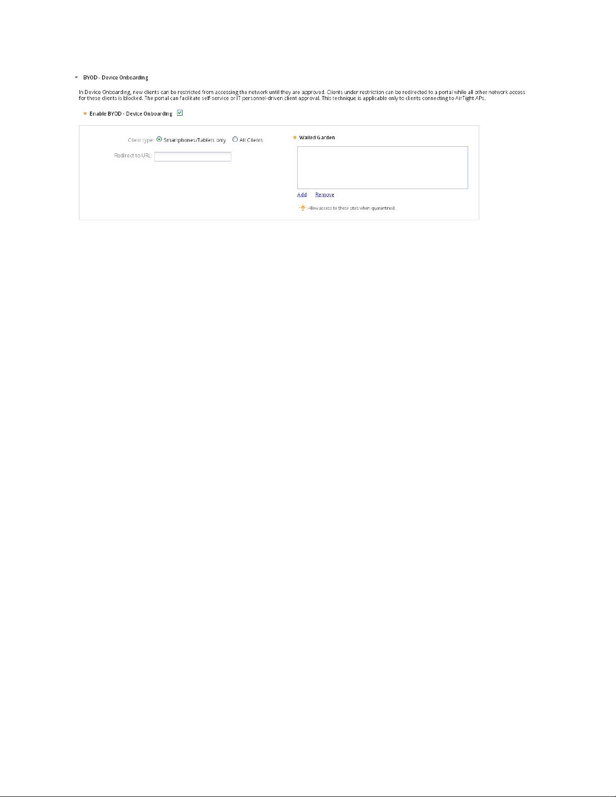
AirTight Management Console User Guide
BYOD - Device Onboarding
To configure BYOD device onboarding, do the following.
Select the Enable Device Onboarding check box to enable BYOD device onboarding.
1.
Select Smartphones/Tablets Only if you want this technique to be enabled for unapproved smart
2.
clients only, and not for other wireless clients (like laptops etc.). Alternatively,select All Clients i f you
want to enable this technique for all types of unapproved wireless clients.
Specify the URL of the splash page in Redirect to URL. Wireless clients will be redirected to this
3.
URL upon making any web request. The IP address or hostname of the splash page host must be
added to the walled garden settings for the redirection to work.
Configure walled garden settings. Click Add to add IP addresses or hostnames to the walled garden.
4.
Click Remove to remove IP addresses or hostnames from the walled garden. Any other hostname or
IP address that needs to be exempted from redirection, can also be added here.
Click Save to save the changes.
5.
Hotspot 2.0 Settings
Hotspot 2.0 provides automatic network discovery and selection with little or no user intervention. It
facilitates cellular offload and Wi-Fi roaming, without the overhead to sign in to the Wi-Fi network
manually. The handoff is automatic and is transparent to the mobile user using a Wi-Fi Alliance
Passpoint-certified mobile device such as laptop, handheld device, smart phone etc.
Passpoint-certified mobile devices can seamlessly connect to an AirTight AP, if the Wi-Fi profile applied
on the AP has Hotspot 2.0 enabled and the corresponding settings configured in it. After Hotspot 2.0
settings configured Wi-Fi profile is applied on the AirT ight AP dep loyed at the operator location, the AP
can advertise available network services enabling Passpoint-certified mobile devices to automatically
discover and select a Wi-Fi network.
A mobile device can request a Hotspot 2.0 AP for information related to the capabilities and services
provided by the AP, without associating with the AP. Based on the information received from the AP, it
can decide whether it wants to connect to the AP or not. This communication between the AP and the
mobile devices takes place using the Access Network Query Protocol (ANQP).
The Hotspot 2.0 settings for the AP correspond to the ANQP elements sent to a querying mobile device
by the Hotspot 2.0 AP to which the Wi-Fi profile is applied.
IMPORTANT! Hotspot 2.0 works only with WPA2 802.1x enterprise security. If you want to configur e
Hotspot 2.0 functionality, you must first set the value in the security mode field (under Security Settings in
the Wi-Fi profile) as WPA2 and ensure that the 802.1x option is selected.
72
Page 84

AirTight Management Console Conf ig ur ati on
The Hotspot 2.0 settings for an AirTight AP are divided into general settings, roaming consortium list,
venue settings, domain name list, 3GPP Cellular network info list, NAI realm list, WAN metrics, Operator
Friendly Name List, connection capability.
General Settings
The General Settings refer to the network configuration. It includes the network access type, network
authentication type element, IP address type etc.
The network type is a predefined list and can have one of the following values.
Private network- Unauthorized users are not permitted on this network. Examples of this access
•
network type are home networks and enterprise networks, which may employ user accounts.
Private network with guest access- The network is a private network offering guest access. An
•
example of this access network type is an enterprise network with guest access.
Chargeable public network- A public network that is available to everyone for a charge. An
•
example of this access network type is a hotel offering in-room Internet access service for a fee.
Free public network- A public network that is available to everyone for free. An example of this
•
access network type is an airport hotspot.
Personal device network - A network of personal devices such as a camera connecting to a printer
•
thereby forming a network to print pictures.
Emergency services only network- The network is dedicated and limited to accessing emergency
•
services only.
Test or experimental- The network is a test or experimental network only.
•
Wildcard- Wildcard access network type. Select this option if you want the AP to reply to the client
•
(mobile device) irrespective of the access network type requested for in the client query.
The network authentication element refers to the list of authentication types. This element is related to
captive portal based authentication systems. A redirect URL can be specified in the General Settings to
redirect the mobile user to the appropriate URL on connecting to the AP.
The network authentication element is a predefined list and can have one of the following values.
Acceptance of terms and conditio n s- Select this option if the network requires the user to accept a
•
set of terms and conditions. You can provide a URL that points to the terms and conditions page in
the Redirect URL field. Providing redirect URL is optional.
Online enrollment- Select this option if online enrolment is supported by the network.
•
http/https redirection- Select this option if the network infrastructure perform http/https redirection.
•
You can optionally provide a redirect URL for http/https redirection.
DNS redirection- Select this option if the network supports DNS redirection.
•
Not configured- Select this option if you don't want to provide specific information when the client
•
queries about network authorization type.
The Homogenous ESSID (HESSID) is a MAC address that is the same for all APs belonging to the same
network. APs with the same HESSID have the same Hotspot 2.0 configuration.
IPv4 address type and IPv6 address type are specified under General Settings.
Roaming Consortiums Element
The roaming consortiums element is configured under Roaming Consortium List. The network could be
member of a roaming consortium or could support service providers. The element consists of one of more
organization identifiers that are unique hexadecimal strings. If this element contains multiple organization
identifiers, it means the network supports multiple service providers or consortia.
73
Page 85

AirTight Management Console User Guide
Venue Settings
The Venue Settings specify the configuration of the venue details where the AP is to be deployed. You
can configure zero or more venues. The venue settings consist of venue groups and venue types. The
venue group is selected from a predefined list of values. The venue type is dependent on the venue
group and the list of values for the venue type is populated based on the venue type selected. You can
select a venue type for the venue group from the list of relevant values for the selected venue group.
The available venue groups are as follows.
Assembly: An arena or an amusement park is a place where a group of people assemble together.
•
Select this venue group if the AP is deployed at such a location.
Business: If the AP is deployed on business premises such as a bank or an office,select this venue
•
group.
Educational: If the AP is deployed at an educational institution such as a school or a university,
•
select this venue group.
Factory and Industrial: If the AP is deployed at a factory or industrial location, select this venue
•
group.
Institutional: If the AP is deployed at a venue hosptial or a rehabilitation center, select this venue
•
group.
Mercantile: If the AP is deployed at a mercantile venue such as a gas station or a shopping mall,
•
select this venue group.
Residential: If the AP is deployed at a residential location such as a hotel or a private residence,
•
select this venue group.
Storage: If the AP is deployed at a storage facility, select this venue group.
•
Utility and Miscellaneous: If AP is deployed at a utility or miscellaneous location, select this venue
•
group
Vehicular: If the AP is deployed on a vehicle such as a train or a boat, select this venue group.
•
Outdoor: If the AP is deployed at an outdoor location such as a kiosk or a bus stop, select this venue
•
group.
Domain Name List
The Domain Name List provides a list of the Hotspot 2.0 operator domain names.
3GPP Cellular Network Info List
The list of mobile networks supported by the AP can be configured under 3GPP Cellular Network Info
List.
NAI Realm List
The NAI Realm List corresponds to the NAI realm element. The NAI realm element provides a list of
network access identifier (NAI) realms corresponding to service providers or other entities whose
networks or services are accessible through the AP. A list of one or more EAP Methods is optionally
included for each NAI realm.
WAN Metrics
Under WAN metrics, you can specify details of the WAN connection available through the WLAN. The link
status and the uplink and downlink speeds can be specified under WAN metrics. Under operator friendly
name list, you can enter a list of operator friendly names along with the language code in which they are
provided to AirTight Management Console.
Connection Capability
74
Page 86

AirTight Management Console Conf ig ur ati on
Field
Description
Network
Type
Select the appropriate network type that the AP is a part of, from the list of
available options.
Network
Auth Type
Select the appropriate IPv4 address type from the available options. The
For NAT related options, NAT must be enabled on the Wi-Fi profile.
Internet
Access
Select this check box if the network provides Internet access to the client
through the AP.
Homogenous Extended Service Set Identifier. This is an optional field
Hotspot 2.0 configuration.
Redirect
URL
URL to which the user is to be redirected on connecting to the AP. This
field is used in conjunction with network authentication type.
Select the appropriate IPv6 address type from the available options. The
Availability of address type not known
Field
Description
Venue
Group
Select the type of venue at which the AP is installed. Different options are
For example, when you select the venue group as Educational, the
Under connection capability, you can specify the protocols supported by the network connection and the
corresponding port numbers and whether the port is open or closed. These settings signify the
capabilities of the wired network that the AP is connected to. They provide information on the connection
status of the most commonly used communication protocols and ports within the hotspot.
Configure Hotspot 2.0 Settings
To configure Hotspot 2.0 Settings, do the following.
Select the Hotspot 2.0 tab in the Add Wi-Fi Profile or Edit Wi-Fi Profile dialog box.
1.
Configure the General Settings.
2.
Select the network authentication type from the list of available options.
following options are available.
Address type not available
Public IPv4 address available
Port-restricted IPv4 addr ess availabl e
IPv4
Address
Single NATed private IPv4 address available
Double NATed private IPv4 address available
Port-restricted IPv4 address and single NATed private IPv4 address
available
Port-restricted IPv4 address and double NATed private IPv4 address
available
HESSID
IPv6
Address
used to identify hotspot APs. APs with the same HESSID have the same
following options are available
Address type not available
Address type available
Enter the roaming consortium list using hex characters. The first 3 roaming consortium from
3.
the list are advertised in the beacon. Up to 32 roaming consortiums can be added here. The
length of the roaming consortium string must be 3 or 5 bytes, that is 6 or 10 hex characters.
Enter the venue details as described in the following table and click Add for each venue
4.
information that you add.
Select the appropriate venue group from the available options.
Venue
Type
presented based on the venue group selected.
75
Page 87

AirTight Management Console User Guide
Field
Description
options available for Venue type are unspecified Educational; School,
Primary; School, Secondary; and University or College
Venue
Name
Name of the venue. Maximum length is 252 bytes. Up to 32 venue names
can be added.
Language
Code
The language code in which the service is to be provided. Refer to the ISO
639.2 standard for the language codes.
Field
Description
Select the appropriate option. The following options are available.
Link
Link down
Link in test
Not Configured- Select this option when the link status is not configured.
Select the Same option if the uplink and downlink speeds are the same.
Select the
different.
Downlink speed, in Kbps or Mbps. Select the appropriate unit of
measurement of the speed
speed.
Uplink speed, in Kbps or Mbps. Select the appr opri ate unit of
measurement of the speed after entering the value for the downlink
speed.
Field
Description
The operator friendly name of the Hotspot 2.0 operator in different
languages. The maximum length must not be more than 252 bytes.
Language
Code
The language code in which the operator friendly name has been specified.
Refer to the ISO 639.2 standard for the language codes.
Enter domain name of the Hotspot 2.0 operator. Click Add to add it. You can enter multiple
5.
domain names in this manner. A maximum of 32 domains can be added. The size of the
domain name must not exceed 255 bytes.
Under 3GPP Cellular Network Info List, enter the 3 digit mobile country code, the 2-3 di git
6.
mobile network code and click Add to add to the list. You can add up to 32 entries here.
Enter the NAI Realm and click Add. You can add upto 32 such realms, each with le ngth upto
7.
255 bytes.
Select the EAP method for that realm and click Add. You can add upto four EAP methods for
8.
one realm. You can see the EAP methods specified for a particular realm when you click the
EAP Settings link for that Realm in the Realm box. The EAP methods must be added in the
sequence of preference. The most preferred EAP method must be added first, followed by the
second prefered method and so on.
Enter the WAN metrics as described the table below.
9.
up- Select this option if the link is up.
Link Status
- Select this option if the link is down.
- Select this option if the link is under test.
Symmetric
Link Status
Downlink
Speed
Different option if the uplink and the downlink speeds are
after entering the value for the downlink
Uplink Speed
Enter the operator friendly name list details. You can have up to 32 entries in the list.
10.
Name
Enter the connection capability details for the network to which the mobile device connects or
11.
requests information from. Based on the port configuration, ensure that you have configured
an appropriate firewall rule in the firewall settings of the Wi-Fi profile. Refer to the following
screenshots for an example of the connection capability and the corresponding rule under
firewall settings. In the connection capability, the port is closed for ICMP requests. The
complementary firewall rule prevents ICMP requests that might result in a denial-of-service
attack. The protocol number 1 in the firewall rule refers to ICMP.
76
Page 88
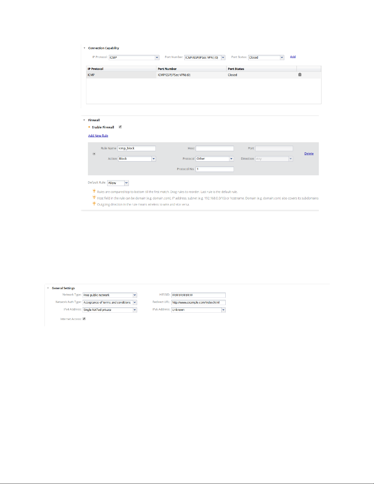
AirTight Management Console Conf ig ur ati on
Click Save. The Wi-Fi profile with the Hotspot 2.0 settings is saved.
12.
The following image is an example of the Hotspot 2.0 configuration.
It describes a Hotspot 2.0 AP that is a part of a free public educational network at the Aalto University. It
is accessible on acceptance of certain terms and conditions. It provides Internet access and the mobile
device is redirected to the URL www.example.com/index.html when it connects to the AP and the mobile
user attempts to access the Internet. The domain names for the operator are exampleoperator.com and
exampleoperator.org. The other settings are as mentioned in the image.
77
Page 89
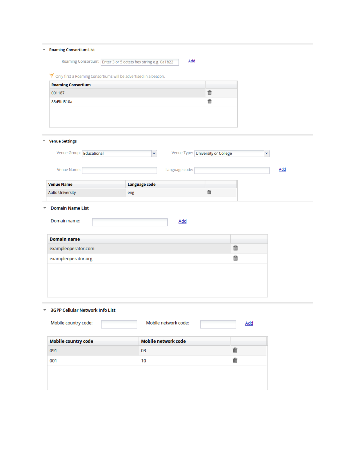
AirTight Management Console User Guide
78
Page 90
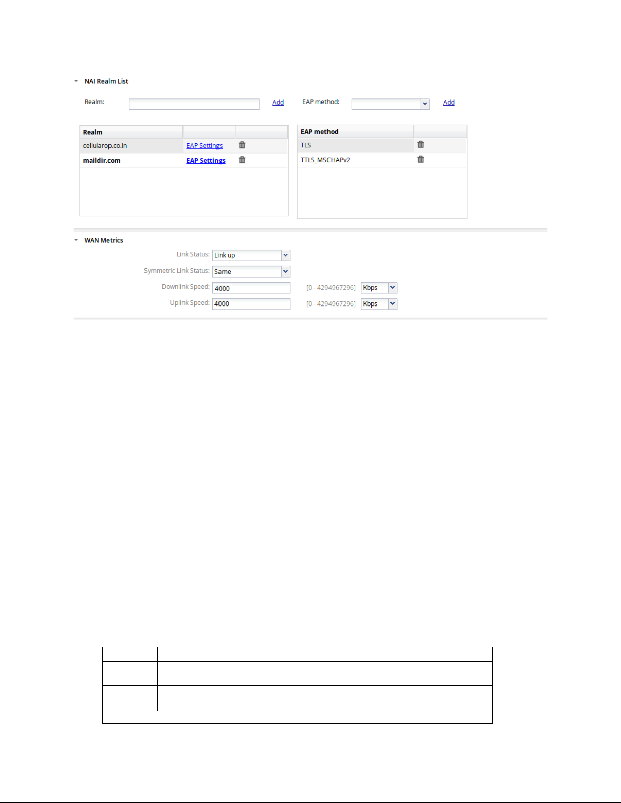
AirTight Management Console Conf ig ur ati on
Field
Description
Profile
Name
Name of the network interface profile. It can have a maximum length of
260 bytes.
Tunnel
Type
Select Tunnel Type as Ethernet over GRE.
Basic Parameters (or Primary Endpoint Parameters)
Manage Network Interface Profiles
A network interface profile represents the tunnel through which network traffic from the configured SSIDs
can be routed to a remote endpoint. The remote endpoint then reroutes this traffic to their respective path
or destination. A network interface profile is used to configure Ethernet over GRE (EoGRE)
settings. Generic Routing Encapsulation (GRE) is a tunneling protocol that can encapsulate a variety of
network layer protocols inside virtu al po int-to-point links over an IP internetwork. EoGRE provides the
ability to setup one or more tunnels from the access point to an aggregating device. Traffic from one or
multiple SSIDs can be channeled through such tunnels. Multiple such tunnels can be configured.
When you configure network interface profiles, you can specify a primary endpoint and a secondary
endpoint. The wireless traffic is bridged to the secondary endpoint if the primary endpoint fails. The
secondary endpoint is optional and is functional only if you enable a secondary endpoint and configure
the host name and local endpoint VLAN for the secondary endpoint.
The secondary endpoint checks for the availability of the primary endpoint and transfers control to the
primary endpoint once it is up and running.
A network interface profile must be attached to an SSID profile when you enable remote bridging on the
SSID profile.
Add Network Interface Profile
To add a network interface profile, do the following.
Go to Configuration>Device Configuration>Network Interfaces.
1.
Enter the values for the network interface profile fields.
2.
79
Page 91

AirTight Management Console User Guide
Field
Description
Remote
Endpoint(IP
Address)
The IP address of the primary remote server or endpoint. It can be left
blank, if you want to use NTP server IP (from DHCP option 42) as the
remote endpoint.
Local
VLAN
The VLAN ID through which AP will form tunnel to the remote endpoint. .
A value between 0 and 4094 should be entered here. Remote Endpoint
must be reachable through this VLAN.
Secondary Endpoint Related Parameters
Enable
Endpoint
Secondary endpoint is remote endpoint to which the wireless traffic is
diverted if the primary endpoint goes down.
Select this check box if you want to enable a secondary endpoint.
Remote
Endpoint(IP
Address)
The IP address of the secondary remote server or endpoint. It can be left
blank, if you want to use NTP server IP (from DHCP option 42) as the
remote endpoint.
Local
VLAN
The secondary VLAN ID through which the wireless network traffic is to be
routed. A value be
Endpoint must be reachable through this VLAN.
Network
Interval
The interval, in seconds, after which the AP checks connectivity with
remote endpoint by sending a ping request packet. This can have a va
between 10 and 3600. The interval must be a multiple of 10.
Network
Count
Count of ping request packets that the AP sends to the remote
endpoint.
Network
Timeout
Time, in seconds, till which the AP waits for a ping reply. The default value
is 60 seconds.
Prefer
Tunnel
Select the check box if you want the AP to check for the availability of the
primary tunnel. If the check box is not selected and the primary tunnel is
down, the AP
Ethernet over GRE
GRE
Key
Key in the primary endpoint GRE header. If configured, key should be
same at both ends of the tunnel. Key is not mandatory to be configured in
GRE tunnel
GRE
Key
Key in the secondary endpoint GRE header. If configured, key should be
same at both ends of the tunnel. Key is not mandatory to be configured in
GRE tunnel
Field
Description
Name of the network interface profile. It can have a maximum
length of 260 bytes.
Tunnel Type
Select Tunnel Type as Ethernet over GRE.
Basic Parameters (or Primary Endpoint Parameters)
Endpoint
Secondary
Endpoint
Probe
Ping Retry
Ping
Primary
Tunnel
over
Secondary
tween 0 and 4094 should be entered here. Remote
lue
The default value is 3.
continues to operate on the secondary tunnel.
Primary
Secondary
Click Save to save the network interface profile.
3.
Edit Network Interface Profile
To edit a network interface profile, do the following.
1.
Go to Configuration>Device Configuration>Network Interfaces.
Make the necessary changes.
2.
Profile Name
80
Page 92

AirTight Management Console Conf ig ur ati on
Field
Description
The IP address of the primary remote server or endpoint. It can
option 42) as the remote endpoint.
The VLAN ID through which AP will form tunnel to the remote
Remote Endpoint must be reachable through this vlanVLAN.
Secondary Endpoint Related Parameters
Secondary endpoint is remote endpoint to which the wireless
endpoint.
The IP address of the secondary remote server or endpoint. It
option 42) as the remote endpoint.
The secondary VLAN ID through which the wireless network
VLAN.
The interval, in seconds, after which the AP checks
interval must be a multiple of 10.
Network Ping Retry
Count
Count of ping request packets that the AP sends to the remote
endpoint.
Network Ping Timeout
Time, in seconds, till which the AP waits for a ping reply.
Select the check box if you want the AP to check for the
operate on the secondary tunnel.
Ethernet over GRE
Key in the primary endpoint GRE header. If configured, key
mandatory to be configured in GRE tunnel
Key in the secondary endpoint GRE header. If configured, key
mandatory to be configured in GRE tunnel
Remote Endpoint(IP
Address)
Local Endpoint VLAN
Enable Secondary
Endpoint
Remote
Endpoint(IP Address)
Local Endpoint VLAN
Network Probe
Interval
be left blank, if you want to use NTP server IP (from DHCP
endpoint. A value between 0 and 4094 should be entered here.
traffic is diverted if the primary endpoint goes down.
Select this check box if you want to enable a secondary
can be left blank, if you want to use NTP server IP (from DHCP
traffic is to be routed. A value between 0 and 4094 should be
entered here. Remote Endpoint must be reachable through this
connectivity with remote endpoint by sending a ping request
packet. This can have a value between 10 and 3600. The
Prefer Primary Tunnel
over Secondary
Tunnel
GRE Primary Key
GRE Secondary Key
availability of the primary tunnel. If the check box is not
selected and the primary tunnel is down, the AP continues to
should be same at both ends of the tunnel. Key is not
should be same at both ends of the tunnel. Key is not
Click Save to save the changes.
3.
Change Location for Network Interfac e Profile
To move the network interface profile to another location, do the following.
Go to Configuration>Device Configuration>Network Interfaces.
1.
Select the location at which the network interface profile has been defined.
2.
Select the check box for the network interface that you want to move to another location.
3.
Click the change location icon. The Select Location dialog box appears.
4.
Select the new location and click OK. The network interface is moved to the new location.
5.
81
Page 93

AirTight Management Console User Guide
Print Network Interface Profile
You can print all the information seen for all network interface profiles. You can choose the columns to be
viewed on the UI by selecting them.
To print the network interface profiles' list for a location, do the following.
Go to Configuration>Device Configuration>Network Interfa ces.
1.
Select the location for which you want to print the network interface profiles' list.
2.
Select the columns that you want in the printed list. Click any column name to select or deselect
3.
columns.
Click the print icon. The print preview of the network interface profiles' list appears.
4.
Click Print to print the list .
5.
Filter/Search Network Interface Profiles
You can filter the network interface profiles' list based on the profile name or tunnel type.
To filter a network interfaces profiles' list, do the following.
Go to Configuration>Device Configuration>Network Interfaces.
1.
Enter the search/filter criteria in the Quick Search box. You may enter the profile name or the tunnel
2.
type to filter the network interface profile data.
Press the Enter key. The network interface profiles matching the search/filter criteria are seen in the
3.
list.
To select the columns to be made visible on the Network Interfaces page, do the following.
Go to Configuration>Device Configuration>Network Interfaces.
1.
Click a column heading. A down arrow appears at the right of this column.
2.
Click the down arrow.
3.
Select Columns option from the menu that appears.
4.
Select the check boxes for the individual columns that are to be made visible on the Network
5.
Interfaces page.
Delete Network Interface Profile
You can delete one or more network interface profiles at the same location at a time.
To delete a network interface profile, do the following.
Go to Configuration>Device Configuration>Network Interfaces.
1.
Select the location for which you want to delete the network interface profile.
2.
Select one or more network interface profiles to delete and click the bin icon the toolbar.
3.
A message asking to confirm deletion of network interface profile appears.
Click Yes to confirm the deletion.
4.
Manage Mesh Profiles
A wireless mesh network is a network where multiple access points (APs) interconnect and communicate
with each other over a wireless link to replace most of the wired connections. The communication
between the APs and routing of network data takes place through the AP radios. The APs that form the
wireless mesh network are the mesh APs.
82
Page 94

AirTight Management Console Conf ig ur ati on
Wireless mesh networks are used indoors or outdoors where laying a wired network may not be a costeffective option. They can be used in specific areas where there is a need to be connected to the network
while moving around in the specified area. They can be used in stadiums, schools, military
establishments etc.
The source mesh AP communicates with the destination mesh APs in the same mesh directly or through
a series of hops from one mesh AP to another until the destination mesh AP is reached. The
communication between wireless clients and APs, and communication between APs takes place through
wireless or wired networks.
AirTight devices with AP capability support creation of a wireless mesh network. A wireless mesh
network, created using AirTight devices, consists of root and non-root APs.
A root AP is an AP that is directly connected to the wired network. A non-root AP is an AP that is not
directly connected to the wired network. It connects to the wired network through the root AP. A non-root
AP can communicate with the root AP directly, or through another non-root AP. There could be one or
more than one root APs and multiple non-root APs in the wireless mesh network .
The root AP connects to a AirTight Wi-Fi/WIPS server through the wired network. All the clients and other
non-root mesh APs talk to the AirTight Wi-Fi/WIPS server through the root AP.
AirTight device models with two radios that are capable of operating in AP mode, that is, SS-300-AT-C-
55, SS-300-AT-C-55-E, SS-300-AT-C-60, SS-300-AT-O-70, C-75, C-75-E and C-65 support mesh
networking. One radio is used as a dedicated mesh radio and the other radio is used to offer Wi-Fi access
to wireless clients. This also means that mesh networking is currently supported for a/n and b/g/n
platforms, but not supported on the 802.11ac platform.
A mesh network created using AirTight devices is logically implemented as a tree topology.
In a tree topology, there is a parent node and there are multiple child nodes. The child node is referred to
as a downlink in the mesh profile configuration. The parent node of a child is referred to as an uplink.
Set up a Mesh Network
To set up a wireless mesh network, you must first identify the APs that would behave as mesh APs. The
APs could be a combination of different AirTight device models supporting mesh networking, or multiple
devices of a single AirTight device model.
You must define a mesh profile on the AirTight Wi-Fi server if you wish to set up a wireless mesh network.
A mesh profile represents the mesh network parameters. You can add, edit and delete mesh profiles.
The mesh profile defined for the wireless mesh network must be applied to one of the radios of the mesh
APs. This radio acts as the dedicated radio to communicate with the other APs on the mesh network.
You must apply a device template with per device configuration enabled, to all the mesh APs. Then, you
must specify which of the mesh APs are root APs. The other APs in the mesh will be treated as non-root
APs, by default.
Once you have defined the mesh parameters and overridden the device template settings for the mesh
AP, you will be able to see a pictorial representation of the mesh network topology in the Locations
section on the AirTight Management Console. For details on viewing the mesh network topology, refer to
the 'View Mesh Topology' section in Manage Location Layout
IMPORTANT! You cannot create a wireless mesh network that is a combination of AirTight APs and APs
from vendors other than AirTight. The mesh network must consist of AirTight APs only.
To set up a wireless mesh network for a location, do the following.
Select a location from the location tree.
1.
.
83
Page 95

AirTight Management Console User Guide
Field
Description
Profile Name
Name of the mesh profile.
SSID
SSID of the mesh profile. This is the network name of the
mesh network.
Max Hop Count
Maximum number of hops in which the wired network can be
reached. For instance, the number of hops for a root AP would
be 0 as it is directly connected to the wired network. Similarly,
the hops for a non
root AP it is 1.
Max downlinks
Maximum number of mesh APs that can directly connect to a
non
maximum number of child nodes that a parent node can have
in the mesh tree topology. You can enter a value between 0
and 5.
Min RSSI
Minimum RSSI for an AP to connect to another AP in the
mesh. An AP requesting to connect to another AP should
have the specified RSSI to be able to connect to the other AP.
You can enter a value between -100 and 0 dbm .
Go to Configuration>Device Configuration>SSID Profiles>Mesh Profiles.
2.
Configure a mesh profile. Refer to the Add Mesh Profile given below for adding a mesh profiles.
3.
4. Go to Configuration>Device Configuration>Device Template.
Define a device template for the AirTight de vice models that are to function as mesh APs. Refer to
5.
Manage Device Templates
for details. Remember to enable the device-specific configuration for this
device template. Ensure that the channel on which the mesh APs are to communicate with each other
is the same for all the AirTight device models that are a part of the wireless mesh network. You must
select the channel manually.
6. Go to Radio Settings under Device Template. Select the mesh profile configured in one of the
previous steps mentioned in this procedure.
Configure other device template details and click Save to save the device template.
7.
Connect all the AirTight devices that are to function as mesh APs to the wired network. You must
8.
connect all Airtight devices irrespective of whether they are root or non-root APs .
Apply the device template to all the devices that are to function as mesh APs.
9.
Disconnect the non-root APs from the wired network. Keep the root APs connected to the wired
10.
network.
Go to Devices>AirTight Devices. Specify the root AP or APs in the wireless mesh network. For
11.
further details on specifying the root and non-root APs, refer to Override Device Template Settings
section. You are done with configuring the mesh network.
Add Mesh Profile
IMPORTANT!:Configuration of mesh profile on both radios is not supported. Configuration of mesh profile
on one radio and WIPS mode on another radio of an AirTight device is not supported. DFS channels are
not available when you manually select channels on the radio on which mesh profile is configured.
To add a mesh profile, do the following.
Go to Configuration>Device Configuration>SSID Profiles>Mesh Profiles.
1.
Select a location from the location tree. A list of mesh profiles available at the location, if any, is seen
2.
in Mesh Profiles.
Click Add New Mesh Profile.
3.
Specify the mesh profile parameters.
4.
-root AP directly comm unicatin g with the
-root or root AP in the mesh network. This indicates the
Click Save to save the newly added mesh profile.
5.
84
Page 96

AirTight Management Console Conf ig ur ati on
Field
Description
Profile Name
Name of the mesh profile.
SSID
SSID of the mesh profile. This is the network name of the
mesh network.
Max Hop Count
Maximum number of hops in which the wired network can be
reached. For instance, the maximum number of hops for a
root AP would be 0 as it is directly connected to the wired
network. Similarly, the maximum hops for a non
directly communicating with the root AP it is 1.
Max downlinks
Maximum number of mesh APs that can directly connect to a
non
maximum number of child nodes that a parent node can have
in the mesh tree topology. You can enter a
and 5.
Min RSSI
Minimum RSSI for an AP to connect to another AP in the
mesh. An AP requesting to connect to another AP should
have the specified RSSI to be able to connect to the other AP.
You can enter a value between -100 and 0 dbm .
Field
Description
SSID
SSID of the mesh profile. This is the network name of
the mesh network.
Max Hop Count
Maximum number of hops in which the wired network
can be reached. For instance, the maximum number of
hops for a root AP would be 0 as it is directly connected
to the wired network. Similarly, the maximum hops for a
non
1.
Max downlinks
Maximum number of mesh APs that can directly connect
to a non
indicates the maximum number of child nodes that a
Edit Mesh Profile
To edit a mesh profile, do the following.
Go to Configuration>Device Configuration>SSID Profiles>Mesh Profiles.
1.
Select the location of the mesh profile to be edited, from the location tree. A list of mesh profiles
2.
available at the location is seen in Mesh Profiles.
Click the name of the mesh profile to edit.
3.
Edit the mesh profile parameters.
4.
-root AP
-root or root AP in the mesh network. This indicates the
value between 0
Click Save to save the changes to the mesh profile.
5.
Create Copy of Mesh Profile
You can create a copy of a mesh profile and use it as a distinct mesh profile by making minor
modifications to it.
To create a copy of a mesh profile, do the following.
Go to Configuration>Device Configuration>SSID Profiles>Mesh Profiles.
1.
Select the location of the mesh profile from the location tree. A list of mesh profiles available at the
2.
location is seen in Mesh Profiles.
Click the name of the mesh profile to save with another name.
3.
Change the name of the mesh profile. Change any other parameters as required.
4.
-root AP directly communicating with the root AP it is
-root or root AP in the mesh network. This
85
Page 97

AirTight Management Console User Guide
parent node can have in the mesh tree topology. You
can enter a value between 0 and 5.
Min RSSI
Minimum RSSI for an AP to connect to another AP in the
mesh. An AP requesting to connect to another AP
should have the specified RSSI to be able to connect to
the other AP. You can enter a value between -100 and 0
dbm.
Click Save to save the changes to the mesh profile.
5.
Copy Mesh Profile to Another Location
To copy a mesh profile from one location to another, do the following.
Go to Configuration>Device Configuration>SSID Profiles>Mesh Profiles.
1.
Select the location at which the mesh file to copy has been created. A list of mesh profiles at the
2.
location is displayed.
Select the mesh profile to be copied to another location.
3.
Click the Copy to location icon. The Select Location dialog box appears.
4.
Select the location to which you want to copy the mesh profile.
5.
Click OK. A copy of the selected mesh profile is created at the selected location.
6.
Print List of Mesh Profiles for Location
You can print a list of mesh profiles that have been defined for a location.
To print a list of mesh profiles at a location, do the following.
Go to Device Configuration>SSID Profiles>Mesh Profiles tab.
1.
Select the columns that you want in the printed list. Click any column name to select or deselect
2.
columns.
Click the Print icon. A print preview of the list appears.
3.
Click Print to print the list .
4.
Delete Mesh Profile
You cannot delete a mesh profile that is in use.
To delete a mesh profile, do the following.
Go to Configuration>Device Configuration>SSID Profiles>Mesh Profiles.
1.
Select the location at which the mesh file to delete has been created. A list of mesh profiles at the
2.
location is displayed.
Select the mesh profile to be deleted.
3.
Click the Delete icon. A message asking to confirm deletion of the mesh profile appears.
4.
Select Yes to confirm deletion and delete the mesh profile.
5.
86
Page 98

AirTight Management Console Conf ig ur ati on
Configure Event Notification
The occurrence of certain events needs to be notified to external entities like Syslog, SNMP, Arcsight and
OPSEC. This configuration is done using the Configuration->Events->Configuration option.
Different types of events occur when the WLAN is functional. These are classified as security,
performance and system events by AirTight Management Console.
Each of these types is listed in the respective tab on the Configuration page.
Security events indicate security vulnerability or breach in your network. Security events are further
classified as follows.
• Misconfigured AP events
• DoS events
• Reconnaissance events
• Rogue AP events
• Man-in-the-middle events
• Ad hoc events
• Cracking events
• MAC spoofing events
• Misbehaving clients events
• Prevention events
Performance events indicate problems in the wireless network. Performance events are further classified
as follows.
• Coverage events
• Configuration events
• Bandwidth events
• Interference events
System events indicate the system health. System events are further classified as follows.
• Troubleshooting events
• Sensor events
• Server events
There are multiple events under each of the security, performance and system event sub-categories.
Some events need to be displayed on the console when they occur. Users or administrators need to be
notified by email when certain events occur. Configure the settings for the events occurring in AirTight
Management Console using the Configuration page.
Do either or all of the following to configure settings for individual events in either of the tabs Security,
Performance, and System, based on your requirement.
• Select the Display check box that corresponds to the event that you want to appear on the
Events page.
• Select the Email check box that corresponds to the event for which you want to send e-mail
notifications to users configured under Configuration->Events->Email Recipients.
• Select the Notify check box that corresponds to the event for which you want notifications sent to
external agents such as SNMP, Syslog, ArcSight, and OPSEC.
• Select the Vulnerability check box that corresponds to the event that makes the WLAN
vulnerable. If any of these events occur, the Security Status widget on the Dashboard displays
the status as Vulnerable.
• Select the option High, Medium, or Low based on the severity of each event.
87
Page 99
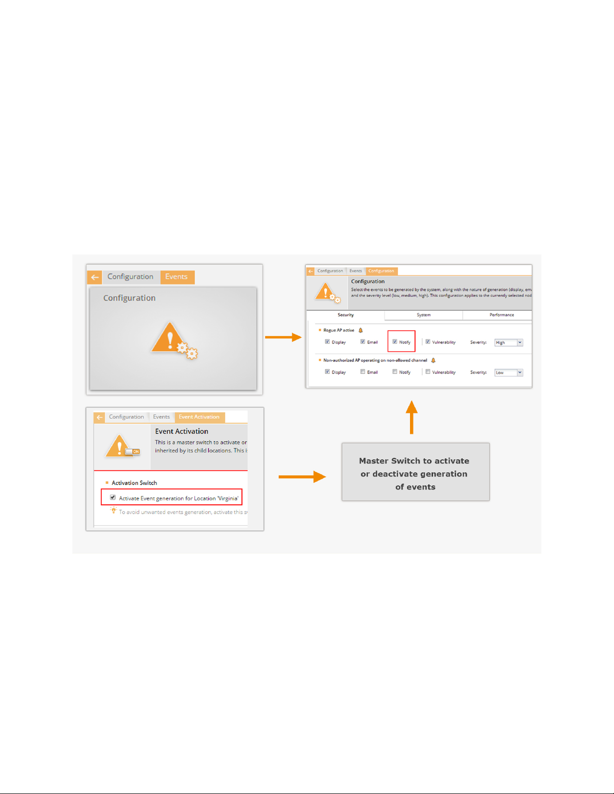
AirTight Management Console User Guide
Note: The event 'Client RF Signature Anomaly Detected' that is visible under Security>MAC Spoofing
option is available in specific deployments only.
Activate Event Generation for Location
Activate event generation for the selected location using the Configuration>Events>Event Activation
option.
Activation Switch defines the high level administrative settings for the selected location. It takes
precedence over any conflicting policies.
Event generation does not happen unles s you selec t the Activate Event Generation for Location
<selected location> check box.
The following figure explains event generation activation.
Activate Event Generation
IMPORTANT: This policy cannot be inherited from the parent- it is specific to the location.
It is recommended that the deployment be stable and fully configured before you select the Activate
Event Generation for Location <selected location> check box.
Click Save to save the changes made to the page. Click Cancel to cancel the unsaved changes on the
page. Click Restore Defaults to restore the default values of the fields on the page.
88
Page 100

AirTight Management Console Conf ig ur ati on
Configure Email Recipi e nt s
Specify the e-mail addresses of the users that need to be notified on occurrence of certain events at the
selected location. The events for which e-mail is to be sent are configured under Configuration->Events-
>Email Recipients.
You can use the e-mail addresses available in the system or add an e-mail address that is not available in
the system.
Separate all the e-mail addresses using a comma or a space, or press Tab or Enter. Click Save to save
the changes made to the page. Click Cancel to cancel the unsaved changes on the page. Click Restore
Defaults to restore the default values of the fields on the page.
Configure Device - Server Communication Settings
Go to Configuration>System>Advanced Settings>Device Communication Key, to set or reset the
communication key used for the communication between the AirTight devices and the AirTight
Management Console server. The communication key is also used to encrypt the communication
between the AirTight devices and server. The communication can happen either using a key or using a
pass phrase.
Use Key for Device - Server Communication
You can set the key for the communication between AirTight devices and the AirTight server directly in
hexadecimals. Select this option if you are comfortable working with hexadecimals.
To set a hexadecimal key for device-server communication, do the following.
Go to Configuration>System>Advanced Settings>Device Communication Key.
1.
Select the Key option to use a key for the communication.
1
Enter a 32 digit hexadecimal key in Enter Key.
2
Enter the same key again in Confirm Key.
3
Click Set to save the changes.
4
Use Passphrase for Device - Server Communication
You can set an alphanumeric passphrase for the communication between AirTight devices and the
AirTight server. Select the Passphrase option if you are not com f or table wor k ing with hexad ec imals.
To set an alphanumeric passphrase for device-server communication, do the following.
Go to Configuration>System>Advanced Settings>Device Communication Key.
2.
Select the Passphrase option to use a key for the communication.
5
Enter an alphanumeric passphrase in Ent er Passphrase.
6
Enter the same passphrase again in Confirm Passphrase.
7
Click Set to save the changes.
8
Reset Communication Key
Click Restore Defaults to reset the communication key.
89
 Loading...