

Page 1
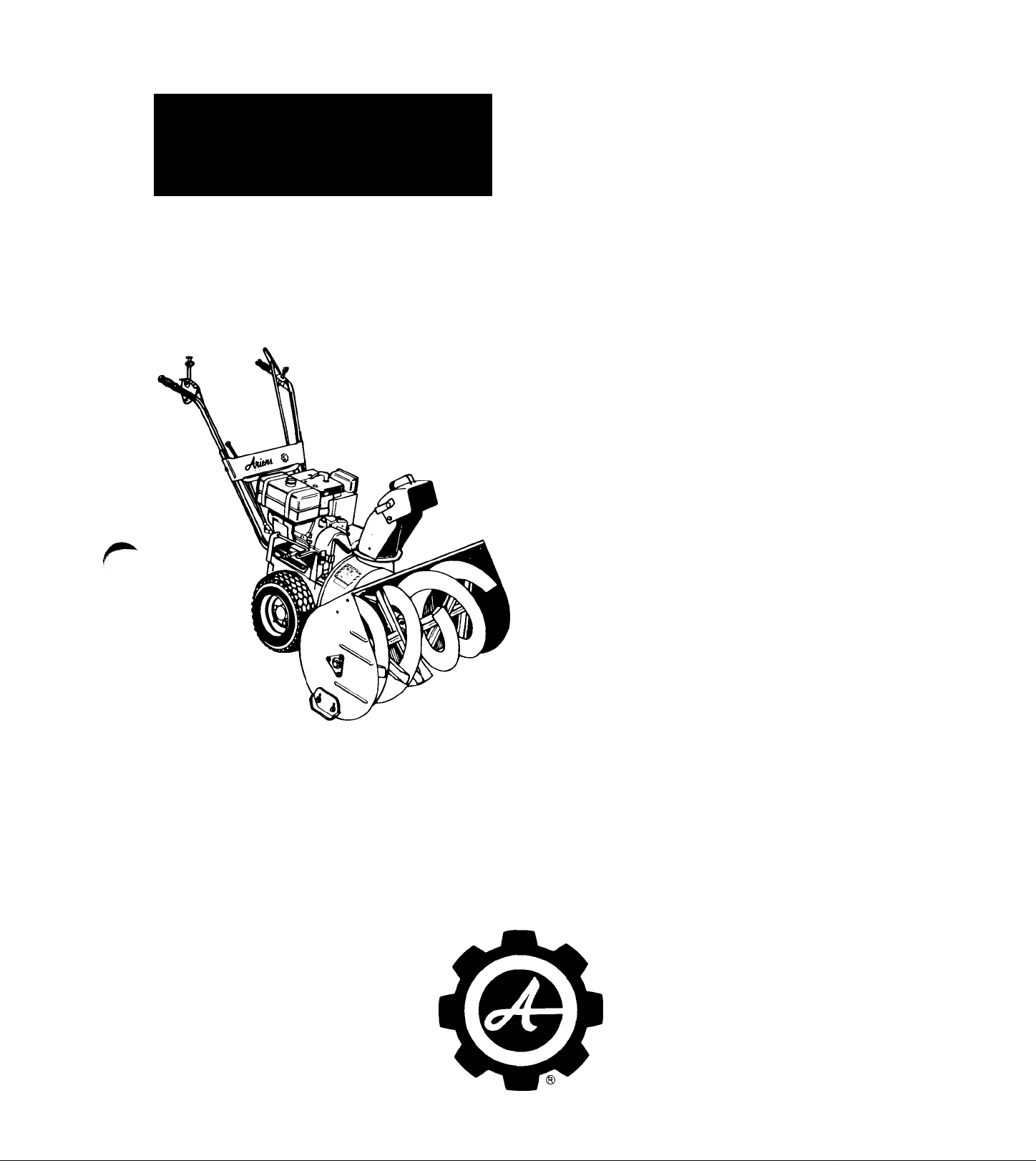
PARTS AND
REPAIR MANUAL
arnien±
10000 - SERIES
TRACTOR
and
SNO-THRO
ATTACHMENT
PRM-10000
1964 THROUGH 1974 INCLUSIVE
Part Number 000136
THIS MANUAL COVERS
THE COMPLETE LINE
OF ARIENS 10000
SERIES SNO-THRO
TRACTORS & ATTACH
MENTS FOR THE
YEARS 1964 THROUGH
1974 INCLUSIVE.
ARIENS COMPANY
BRILLION, WIS. 54110
Page 2

INDEX
10000 SNO-THRO
1964 THROUGH 1974
MODEL NUMBER and SERIAL NUMBER of your machine will be
stamped on the frame or printed on the Serial Number Decal which
will be located on the frame near the engine on all Ariens products.
Do not be confused with other identification plates located on the
engine or attachments.
1. EXPLODED VIEW AND PARTS LIST ................................................................................................................................................... 4-38
Ш MOP. NO
MFD. B\^4iea±co.
BeiUlON. WISCONSIN U. S. A
000000 sER.'No. 000000
YEAR DESCRIPTION MODEL
1974
1973
1972-71
32" SNO-THRO ATTACHMENT 910013
24” SNO-THRO ATTACHMENT
8 H.P. SNO-THRO 910018
6 H.P. SNO-THRO
8 H.P. SNO-THRO
8 H.P. SNO-THRO
7 H.P. SNO-THRO
7 H.P. SNO-THRO
8 H.P. SNO-THRO
8 H.P. SNO-THRO
32" SNO-THRO ATTACHMENT
6 H.P. SNO-THRO
8 H.P. SNO-THRO
24” SNO-THRO ATTACHMENT
8 H.P. SNO-THRO
8 H.P. SNO-THRO
32" SNO-THRO ATTACHMENT
24" SNO-THRO ATTACHMENT
6 H.P. SNO-THRO 910002
7 H.P. SNO-THRO TRACTOR
7 H.P. SNO-THRO
7 H.P. SNO-THRO
5 H.P. SNO-THRO 910965
32” SNO-THRO ATTACHMENT 910955
24" SNO-THRO ATTACHMENT
910017
910019
910020
910006
910007
910008
910009
910010
910013
910014
910016
910017
910018 000101-002000 7 through 9
910021
910955 009300-009427 7 through 9
910995
910942
910954
910962
910995
SERIAL PAGE ND.
007001 & Up 4 through 6
005001-032264 4 through 6
002001-018319 4 through 6
000101-012804
000101-000264
000101-010595 7 through 9
000101 & Up
000101-025430 7 through 9
000101 & Up 7 through 9
000101-006690 7 through 9
000101-007000 7 through 9
000101-001300
000101-002202 7 through 9
000101-005000
000101-002204
080000-118676 7 through 9
000001-015781
000001-000874 10 through 12
000001-009013 10 through 12
000001-021453 10 through 12
000001-010850
000001-009246 10 through 12
000001-080000
4 through 6
4 through 6
7 through 9
7 through 9
7 through 9
7 through 9
10 through 12
10 through 12
10 through 12
m
1970
1969
1968
7 H.P. SNO-THRO TRACTOR 10942
7 H.P. SNO-THRO 10954
7 H.P. SNO-THRO
5 H.P. SNO-THRO 10965 007201-015725
32” SNO-THRO ATTACHMENT
24” SNO-THRO ATTACHMENT
7 H.P. SNO-THRO
7 H.P. SNO-THRO
5 H.P. SNO-THRO
6 H.P. SNO-THRO 10969
6 H.P. SNO-THRO 10970
4 H.P. SNO-THRO 10M4
5 H.P. SNO-THRO
6 H.P. SNO-THRO
6 H.P. SNO-THRO 10M6D 045201-058961 24 through 26
7 H.P. SNO-THRO 10M7D 000101-003590 24 through 26
10962
10955
10995
10954
10962
10965
10M5
10M6 046101-051426
Page 2
000001-000336
003001-006796
006001-024279
003101-006921 13 through 16
027601-055213 13 through 16
000001-003000 17 through 20
000001-006000
000001-007200 17 through 20
000001-000615
000001-013824
012101-015755
006801-014007 24 through 26
13 through 16
13 through 16
13 through 16
13 through 16
17 through 20
17 through 20
17 through 20
21 through 23
24 through 26
Page 3

1967-66 4 H.P. SNO-THRO
5 H.P SNO-THRO
6 H.P SNO-THRO
6 H.P. SNO-THRO
10M4
10M5
10M6
10M6D
004501-012100
000001-006801
032501-046100
025501-045200
27 through 29
30 through 32
30 through 32
30 through 32
r
1965 6 H.P. SNO-THRO
6 H.P. SNO-THRO
1964 3.5 H.P. SNO-THRO
6 H.P. SNO-THRO
6 H.P. SNO-THRO
2. SERVICE AND ADJUSTMENTS............................................................................................................................................................39-43
3. LUBRICATION
4. TROUBLE SHOOTING
5. BELT CROSS REFERENCE
6. ENGINE CROSS REFERENCE..............................................................................................................................................................46-48
10ML60
10ML60D
10ML35
10ML60
10ML60D
024001-032500
017001-025500
006001-008404 36 through 38
015001-024000
006001-017000
33 through 35
33 through 35
36 through 38
36 through 38
45
45
r
r
Page 3
Page 4
»1
I
# i
M
■
Page 4
' ' «*
Page 5

e
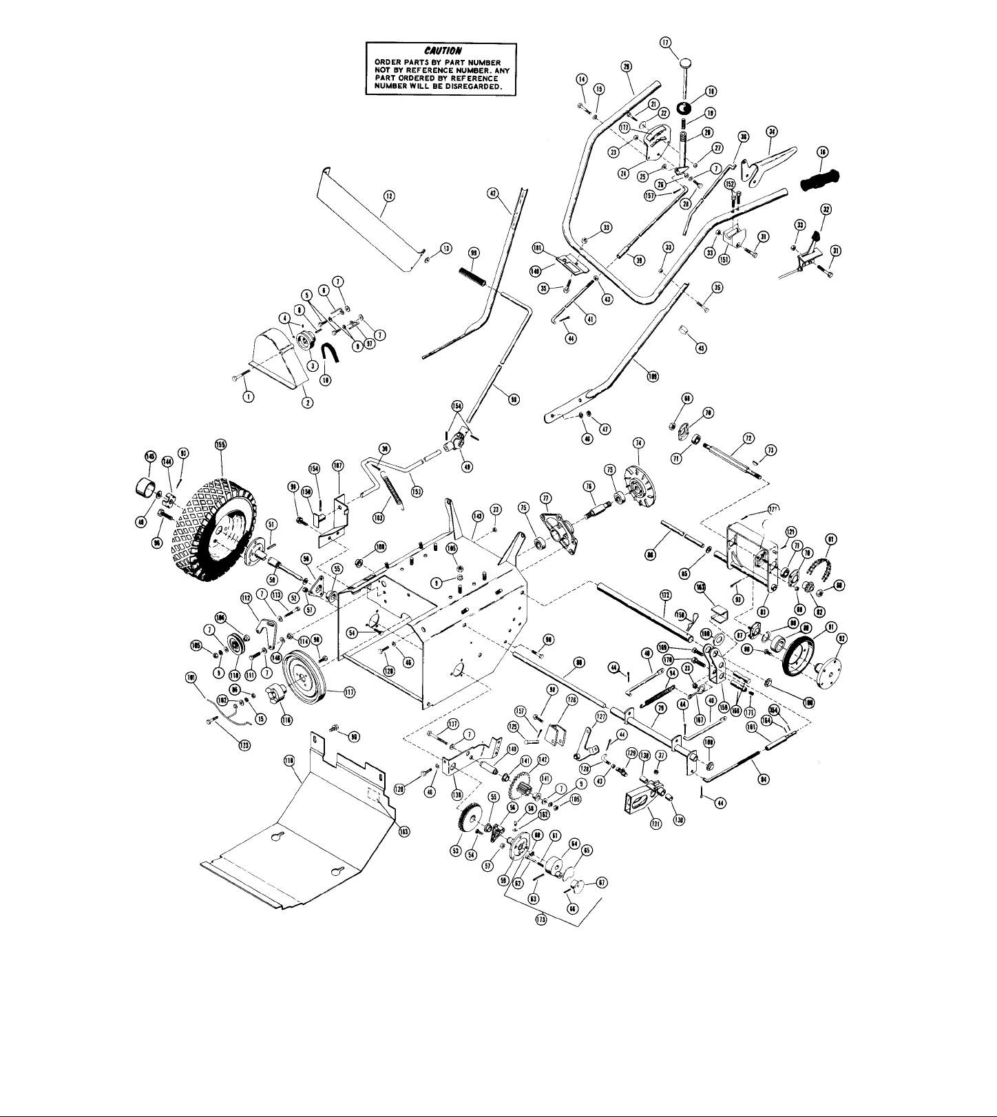
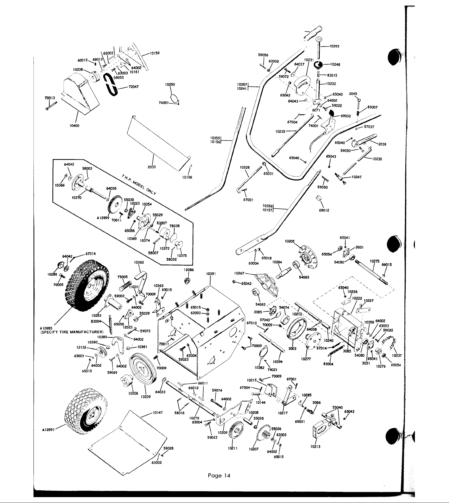
REF PART STOCK
NO. CODE
NO.
1 70013
2
10500
3 10238
10477
3
4
60012
5
59053
6
10160
7
64002
8
66013
8 66018
9 63003
10 72047
10 72072
12
2033
13
10196
14
59056
IS 63002
16 75006
17
10293
18 10248
83015
19
20 10232 s
21 59072
22 64037
23 65042
24
10231 s
25 64043
6071 M
26
27
65070
28 59022
10464
29
29 10463
30
67018
31 59062
32 69085
32
69086
33
65040
34 22071
35
59050
36 10465
37
65043
39 10235
40 10472
41 10228
42
10156
42 10355
43 65031
44
67001
45
69012
63004
46
47
65018
48 10366
622010
49
50 10370
51
58003
52 64036
S3 612999
54
70011
55 55030
56 12023
57
65056
58 22093
59 610938
60 55029
83007
61
10374
62
63 58042
64
10372
65
78038
S6 58032
67
10375
65054
88
65094
69
n 3031
71
54989
72 10275
66015
73
74
10546
75 54063
78 10548
77 10547
71 10513
10471
1 ••
10237
1 P*
19276
В
19473
' il
10544
IS
64038
10212
{!
3085
17
57043
i . m
54974
n
96 70009
3003
81
10277
92
67014
93
94 83089
65032
9S
70032
96
97 10161
10482
99
M
F
M
M
M
s
F
M Washer • 5/16 Wrought Plated 9 9
s
s
M
F
F
0
M
s
s
M
s
s
M
M
M
M
M
M
F
M
M
M
M
F
F
M
S
M
S
M
M
s
s
M
M
s
M
M
M
M
M
M
M
M
M
M
M
M
M
M
M
M
M
M
M
M
M
s
M
M
M
M
s
M
s Hex Shaft
s Key - Woodruff No. 5
M Drive Plate
M
M
M
s Front Clutch Lever
s Rod
M
M
s
s Adjustment Link
s
s Bracket Pin
s Bearing Flange
M Snap Ring
M
M
F Friction Wheel
M Friction Disc Hub
F
M
M
s Wheel Bolt -1/2-20
M L.H. Belt Finger
s
NO. REQ'D
oo о
DESCRIPTION
Belt Cover Bolt
Duter Belt Guard
Engine Sheave
Engine Sheave
Setscrew -5/16-18x3/8 Nytok
Cap Screw - 5/16-24 UNF x 3/4 H.H., Z.P.
R.H. Belt Finger
Key-SAE 1035
Key
Lockwasher - 5/16 SAE Std. Plated
Belt
Belt
Handle Bar Panel
Handle Bar Washer
Cap Screw • 1/4-20 UNC x 1-1/4 H.H. Plated 2 2
Lockwasher • 1 /4 SAE Std., Plated
Grip
Shift Release Handle
Shift Ball
Spring 1 1
Shift Handle 1 1
Cap Screw • 1/4-20 UNC x 1-1/4 H.H., H.T. 1 1
Washer - 9/32 l.D. x 1-1/4 O.D. x 1/16 Plater 1 1 126
Locknut • 5/16-18 Hex, Plated 3 3
Shift Quadrant 1 1
Washer-SAE 3/8-13/32 l.D. x 13/16 O.D.
X 1/16 Plated 1 1
Spacer Bushing
Locknut -1/4-20 1 1
Cap Screw - 5/16-18 UNC x 3/4 H.H., Z.P. 1 1
Upper Handle Bar
Upper Handle Bar 1
Cotter Pin -1/8 X 1/2 1 1
Cap Screw -1/4-20 X 1-3/4
Throttle Control
Throttle Control 1
Locknut -1/4-20 Hex, Plated 7 7
Clutch Handle 1 1
Cap Screw -1/4-20 UNC x 1-1/2 H.H. Plated 5 5
Clutch Rod 1
Locknut - 5/16-24 Hex, Plated
Upper Shift Rod
Clutch Link
Lower Shift Rod 1 1
R.H. Lower Handle Bar
R.H. Lower Handle Bar
Nut-5/16-24 Hex, Plated
Cotter Pin - 3/32 X 3/4 Plated
Cable Clamp
Lockwasher - 3/8 SAE Std. Plated
Nut-3/8-16 Hex, Plated
Push Nut
Universal Joint 1 1
R.H. Axle Shaft 1 1
Roll Pin-3/16x1-1/4
Washer - .880 l.D. x 1.3880 O.D. x .062 1
Differential Assembly
Ribbed Neck Bolt -1/4-20 x 5/8 Plated 6 6 163
Bushing
Bearing Support
Flange Whi2lock Nut -1/4-20 Plated
Zerk Fitting
L.H. Axle
Bushing
Spring
Pin
Groove Pin
Lockout Hub
Differential Lock Decal
Roll Pin - 3/32 x 1
Knob 1 1
Locknut -1/2-20 Hex, Centerlock
Locknut - No. 10-24 Plated 8 8
Bearing Flange
Ball Bearing
Ball Bearing
Spindle
Bearing Housing
Chain
Sprocket
Disc Bracket
Shim Washer • .505 l.D. x .775 O.D. x 24 Ga.
Thrust Bearing
Flange Whiziock Screw - 5/16-18 x 2/2 Platec
Cotter Pin -1/8 X 1-1/4 Plated
Spring
Nut 1/4-20
Clutch Handle
O)
о о
о
о о
о
СП
оэ
1 1
1 1
1
1
2 2
2 2
1 1
1
1
8
8
1
1
1 1
2 2
3
3
2 2
1 1
1 1
1 1
1
2 2
1
1
1 1 151
1 1 152
2 2 153
1
1
2 2
5 5
1 1
8 8
4 4
1 1
1 1
1
1 1
2 2 164
2 2 167
6 6
1 1
1 1
2 2
1 1
1 1
1 1
1 1
1 1
1 1
2 2
2 2
2 2
1 1
1 1
1 1
2 2
1 1
1 1
1
1
1 1
1 1
1 1
1 1
1 1
1
1
1
2 2
1
1
1
1
18 18
1
1
1
1
1
1
1
6
6
1
1
REF
N0.
161
162
171
181
101
102
103
105
106
107
108
109
109
110
111
112
113
114
116
117
118
120
121
122
123
125
127
128
129
130
131
137
138
141
142
143
143
144
148
149
150
154
155
157
158
159
160
168
169
170
172
173
174
177
140
145
183
75013
10492
64007
83004
65015
10360
10479
12086
10157
10356
12132
59069
10389
59073
10361
10206
10239
10460
59023
67019
10545
59001
10144
10215
10476
10484
3086
55040
510009
59074
10462
10208
55026
524002
10458
10459
3376
3377
64038
10483
10481
22129
74039
10480
58034
610985
67004
67002
10541
64058
10543
63025
10542
58035
10540
22135
60026
59002
60012
10545
510004
10373
78016
78230
78245
78010
78189
78231
78191
78225
75040
COOE
NO.
99
SUGGESTED PARTS STOCK CODE
F = Fast Moving Parts
M = Medium Moving Parts
S = Slow Moving Parts
0 = Customer Order Only
NO. REQ'D
O) ooo
DESCRIPTION
Grip 1 1
Belt Finger 1
Washer • 1/4 Std. 1
Spring 1 1
Nut-5/16-18 Hex, Plated 6 6
Bearing Spacer 1 1
Clutch Bracket 1 1
Cap 3 3
L.H. Lower Handle Bar 1
L.H. Lower Handle Bar 1
Idler 1 1
Cap Screw -5/16-18 UNCx 1-1/4 H.H., Plated 1 1
Idler Arm 1 1
Cap Screw 5/16-18 UNCx 1-3/4 H.H.. Plated 1 1
Shoulder Spacer 1 1
Jaw Coupling 1 1
Driven Sheave 1 1
Bottom Cover 1 1
Cap Screw-3/8-16 UNCx 3/4 H.H.. Plated 4 4
Hair Pin Cotter 2 2
Clutch Rod 1 1
Cap Screw • 1/4-20 x 3/4 1
Clevis Pin 1 1
Lever Bracket 1 1
Transfer Lever 1 1
Connecting Link 1 1
Bail Joint 1 1
Bushing 2 2
Sliding Fork (Includes Bushing) 1 1
Cap Screw-5/16-18 UNCx 2-3/4 H.H., Plated 1 1
Support Bracket 1 1
Pinion Stub Shaft 1 1
Bushing 2 2
Pinion and Sprocket (Includes Bushings) 1 1
Tractor Frame 1
Tractor Frame 1
Spindle Cup 1 1
Hub Cap 1 1
Washer .505 l.D. .755 O.D. x 34 GA. 1 1
Rod Hanger Bracket 1 1
Clutch Interlock Lever 1 1
Handle Pivot 1 1
Tapping Screws 2 2
Engagement Rod 1 1
Roll Pin 4 4
Tire and Wheel Assembly
consisting of: Req'd per Wheel 2 2
71046 Tire (Carlisle Stud Tread
71050 Tube 1
71052 Rim 1
Cotter Pin 1/8 X 1 Plated
Cotter Pin
Clutch Engagement Yoke
Washer - .500 to .505 l.D. x 1 O.D. x .062
Adjustment Tube
Lockwasher
Adapter Spacer
Roll Pin 1/8 X 1/2
Spring Hook
Rod Adapter
Setscrew-5/16-18x 1/2
Cap Screw - 5/16-18 x 5/8
Setscrew - 5/16-18 x 3/8
Clutch Rod
Lockout Hub Assembly
Carburetor Cover
Sno Shift Label
Label • In-Out
Disc Adjustment Decal
Helicon Patent Label (Not lllus.)
Air Cleaner Decal (Not lllus.)
Engine Label (Not lllus.)
Engine Decal - 8 H.P. (Not lllus.)
Engine Decal - 6 H.P. (Not lllus.)
Plug (Not lllus.)
NOT ILLUSTRATED
*6 H.P. Engine (Tecumseh HSK-60
*8 H.P. Engine (Tecumseh HSK-80
*0rder Replacement Engine
And/Or Engine Replacement
Parts From Your Nearest
Engine Service Central.
Tire Available Only) 1
75361J) or Replacement
155020) or Replacement
^ *—iM
о oo
о oo
о о О)
Page 5
Page 6
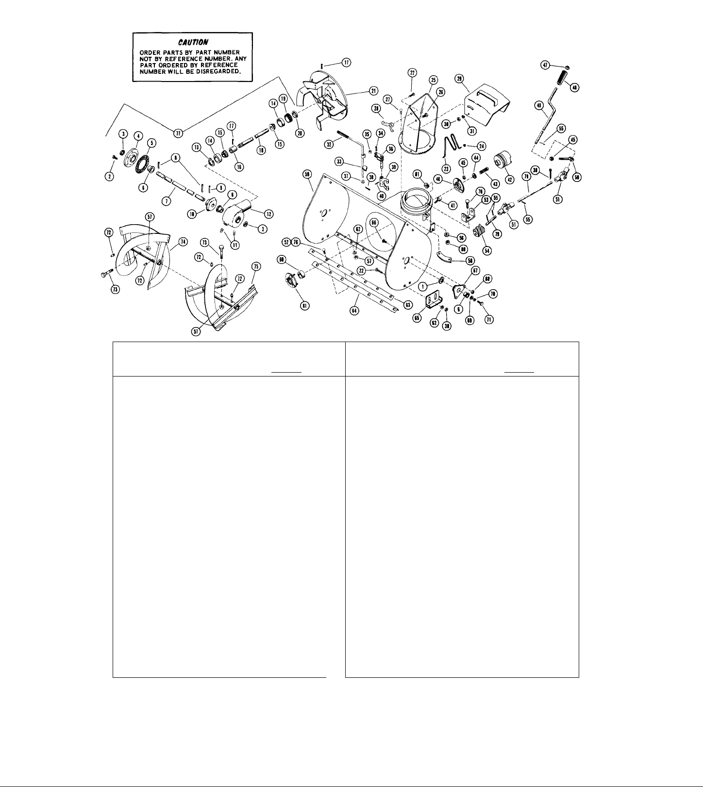
ORDER PARTS BY PART NUMBER
eMumm
NOT BY REFERENCE NUMBER. ANY
PART ORDERED BY REFERENCE
NUMBER WILL BE DISREGARDED.
; -'V
--
@
‘i ¥
®
---
SUGGESTED
PARTS STOCKING CODE
F = Fast Moving Parts
M = Medium Moving Parts
S = Slow Moving Parts
0 = Customer Order Only
REF.
PART
NO.
NO.
1
64046
2 70012
3
56061
4
10181
5
10108
6 55035
7
10384
7
10299
8 58030
9
58022
*10 10183
11 1138
12
10180
13 57032
14
54044
15 54045
10107
16
17 58007
•18 10177
10371
19
20 56062
21 10178
22 62010
23 10393
24
22122
25 10437
26 59023 M
27
74026 M
28
10193
29 510012
30 65039
31 63004
32 75004
33 10390
58017 M
34
3034
35
36 10186
37
10260
38 67004
39 1008
40
58016 M
41
70031
42
10176
43 83014
44
64048
45
65040
46 10142
47
10198
48 75039
STOCK DESCRIPTION
CODE
Washer 1.505 O.D. x 1.005 I.D. x 1/16
M
Flange Whiziock Screw 1/4*20 x 3/4
M
Seal
F
Gear Case Flange
F
Gasket
F
Bushing
M
Front Gear Shaft 32"
M
Front Gear Shaft 24"
M
Roll Pin 3/16x1-1/2 2
M
Roll Pin 5/16 X 1-3/8 1
M
Helicon Gear
F
Pipe Plug 3/8 Sq. Hd.
M
Gear Case
M
Snap Ring
M
Bearing Cup
M
Bearing Cone
M
Bearing Spacer
s
Roll Pin 1/4 X 1-1/4
M
Helicon Pinion Shaft
M
Adjustment Plug
M
Seal
F
Fan
M
Carriage Bolt 3/8*16 x 3/4
M
Safety Wire
s
Fastener
s
Discharge Chute
M
Cap Screw 3/8*16 x 3/4 H.H.
Taptite No. 10*24 x 3/8
M Wing Nut
M Deflector
F
Locknut 3/8-16
F
Lockwasher 3/8 Std.
M
Grip 1/2 I.D.
Fork Cam
s
Roll Pin 5/16 X 1-1/4
Roller
s
Fork Shaft
s
Wave Washer
s
Cotter Pin 1/8 X 1
M
Clutch Fork
S
Roll Pin 3/16x1
Flange Whiziock Screw 3/8*16 x 3/4
M
Jaw Clutch
F
Spring
M
Washer 1.375 O.D. x .755 I.D. x 1/16
M
Locknut 1/4*20
F
Bearing Flange
F
Cap
M
Grip
M
NO.
REQ'D
CO
O)
o
o
O)
2 2 2
5 5 5
2
1
1
4
1
1 1
2
1
1 1
2
2 2
1
3 3
1
1 1
1 1
1
5
2 2
2 2
6 6 6
1 1
6 6
2 2 2
1 1
2
2
2 2 2 2
1 1 1
1 1 1
4 4
1 1 1
P- OO
r*
o
o o
o
o o
03
03 03
2 2
1 1
1 1
4 4
1
1 1
2 2
1 1
1 1
2 2 2
1 1
1 1
2 2
2 2
1 1
3 3
1 1
1 1
1 1
1 1
5 5
1
1 1
2 2
1 1
2 2
1 1
1 1
6 6
1
1 1
1
1 1
1 1 1
1 1
1
1 1
1 1 1
2 2
1
1 1
2 2 2
1 1 1
4 4
2 2 1
2 2 1
REF. PART STOCK
NO. NO. CODE
2
5
2
1
1
4
2
1
1
2
1
1
1
5
1
6
1
2
2
1
1
1
49 10487
49
50 10289
51
52
53
54
55
56 63023
57
58
59 510010
59
60 54063
61
62
63 10387
63 10164
65 10165
66 70011
67
68
69 64047
70 63006
71
72
73
74
74 510007
75 524004
75 510008
76 62011
77
77
78 10488
79 10494
80 65015
81
82
83
84
NOTE
DESCRIPTION
10478
622010 M
62026
22123
22110
58034
65042
10438
510011
3017 F
64002
10184
65056
59024
22093
10195
524003
510002
610984
70026
78222
78055
78174
s Chute Control Crank (For 8 H.P. Only)
s Chute Control Crank
s Rod Hanger
Universal Joint
M
Carriage Bolt 5/16-18 x 5/8
M
Worm Clevis
M
Worm Gear
M
Roll Pin 1/8 X 3/4
M
Lockwasher
M
Locknut 5/16-18 7
s
Chute Clamp
0
Blower Housing 24"
0
Blower Housing 32"
M
Ball Bearing
Bearing Flange
M
Washer 5/16
F
Scraper Blade
F Scraper Blade
Runner
F
Ribbed Neck Bolt 1/4-20 x 5/8
M
M
Bearing Support
M
Whiziock Nut 1/4*20
M
Washer 1.441 O.D. x.511 I.D. x 1/8
M
Lockwasher 1/2 Std.
S
Cap Screw 1/2-13 X 1 H.H.
M
Zerk Fitting
F
Shear Bolt
S
R.H. Rake 32" Includes Zerks 1
S
R.H.Rake24" Includes Zerks
S
L.H. Rake32" Includes Zerks 1
S
L.H. Rake 24" Includes Zerks
M
Carriage Bolt 5/16*18 x 3/4 1 1
0
32" Gear Case Auembly 1
s
24" Gear Case Assembly
s
Connector Rod
s
Worm Shaft
M
Nut 5/16-18 1 1
s
Nut Retainer 3/8-16
0
Caution Label
0
Clutch Instruction Decal
0
Ariens Nameplate
*10183 and 10177 Sold In Pairs Only
Use Ariens MP 90 Premium Gear Lubricant
in 10180 Gear Case
NO. REQ'D
CO r«* oo
o o o
1
1
1
1
1
2
5 7
1 1
1
1
1 4
1 1
9
3 3
1
1
1
1
1 1
9 11
1
1
2
2
6
6
2 2
6 6
2 2
2 2
2
2
4 4
2
2
1
1
1
1
1
2 2
1
1
1 1
1
1
1 1
4
1 1
1 1
2 2
1 1
#
m
Page 6
Page 7
NO. REQ'D
>0< D^*0№
m C O o
REF.
PART
NO.
NO.
64046 Washer 1.505 OD x 1.006 ID x 1/16
1
70012
2
3 56061 Seal
10181 Gear Case Flai^e
4
10108 Gasket
5
55035 Bushing
6
7 10384
10299 Front Gear Shaft
7
58030 RoU Pin 3/16 X 1-1/2
8
58022 Roll Pin 5/16 X 1-3/8
9
*10 10183 Helicon Gear
1138 Pipe Pli^ 3/8 Sq. Hd,
11
12 10180 Gear Case
57032
13
54044 Bearing Cup
14
54045 Bearing Cone
15
16 10107 Bearing Spacer
17 58007 Roll Pin 1/4 X 1-1/4
10177 Helicon Pinion Shaft 1 1 1 1 1 1
*18
19 10371 Adjustment Plug
20 56062
21 10178 Fan
62010
22
10393 Safety Wire
23
22122 Fastener 2 2 2 2 2 2
24
10437 Discharge Chute
25
59023
26
27 74026 TapUte #10-24 x 3/8
10193
28
29 10191 Deflector 1
65039
30
31 63004
75004 Grip 1/2 ID 1 1 1 1 1 1
32
33 10390 Fork Cam
34 58017 RoU Pin 5/16 X 1-1/4 1 1 1 1 1
3034 RoUer
35
36 10186
10260
37
67004
38
39
1008 Clutch Fork
40 58016
70031
41
10176
42
83014
43
64048
44
45 65040 Locknut 1/4-20
46 10142 Bearing Flange
Flange Whizlock Screw 1/4-20 x 3/4
Front Gear Shaft
Snap Rii^
Seal 1 1 1 1 1
Carriage Bolt 3/8-16 x 3/4 5 5 5 5 5 5
Cap Screw 3/8-16 x 3/4 H.H. 2
Wing Nut
Locknut 3/8-16
Lockwasher 3/8 2 2 2 2 2 2
Fork Shaft 1 1 1 1 1
Wave Washer
Cotter Pin 1/8 X 1 2 2 2 2 2
RoU Pin 3/16 X 1
Jaw Clutch
Spring
Washer 1.375 OD x .755 ID x 1/16
DESCRIPTION
Flange Whizlock Screw 3/8-16 x 1/2
QQQ004
OOOO O
II § 8
o> o>
1 I 1 1
2 222 2 2
5 5 5 5 5 5 48
2 2 2 2 2 2
1 1 1 1 1
1 1 1 1 1 1
4 4 4 4 4 4 51
1 1 1
1 1 1
2 2 2 2 2 2 54 22110 Worm Gear
1 1 1
1 1 1
2 2 2
2 2 2
1 1 1 1 1
1 111 1 1
2 2 2
2
2 2 2 2 2
1 1 1
3 3 3
3 3 3
1 1 1 1 1 1
1 1 1 1 1
1 111 1 1
1 1 1 1 1 1
2 2 2 2 2
6 6 6 6 6 6
1 1 1 1 1
1 1
1 1 1
6 6 6 6 6 6
1 1 1 1
1
1 1 1 1
1 1 1 1 1
1 1 1 1 1
2 2
2 2
2
2
2 2
1
1
1 1 1 1
1 1 1 1
4 4 4 4 4 4
1 1 1 1
z> o
REF.
PART
NO.
NO.
47
10198
75039 Grip 1 122
49 10487
49
10478 Chute Control Crank
50 10289 Rod Hanger 1 1
622010 Universal Joint
52 62026
53 22123 Worm Clevis
55 58034 Roll Pin 1/8 X 3/4
56 63023 Lockwasher
57 65042 Locknut 5/16-18
58 10438 Chute Clamp
59 10457 Blower Housing 24”
59 10447 Blower Housir^ 32”
60
54063 Ball Bearing
3017
61
62 64002 Washer 5/16 9 4 4
63 10387 Scraper Blade
63
10164 Scraper Blade
64
10446 Reinforced Angle 1 1
65 10165
66 70011 Ribbed Neck Bolt 1/4-20 x 5/8 6 6 6
67 10184 Bearing Support
68 65056 Whizlock Nut 1/4-20
69
64047 Washer 1.441 OD x .511 ID x 1/8
70
63006 Lockwasher 1/2
71 59024
72 10354 Zerk Fitting
73
10195
74 10433 R, H. Rake 1
74 10431
75 10434
75 10432 L. H. Rake 1
62011
76
77 510002 32” Gear Case Assembly
77
610984 24” Gear Case Assembly 1
78
10488
79 10494
80
65015
81
70026 Nut Retainer 3/8-16
78222
78055
78174
NOTE *10183 And 10177 Sold Use Ariens MP 90 Premium
1 1
1 1
2 2
1 1
2 2
2 2
1 1
o o
1
2
2
DESCRIPTION
Cap
Chute Control Crank (For 8 H.P.only) 1
Carriage Bolt 5/16-18 x 5/8
Bearing Flange
Runner 2 2 2
Cap Screw 1/2-13 x 1 H. H.
Shear Bolt 2 2
R. H. Rake 1
L. H. Rake
Carriage Bolt 5/16-18 x 3/4 1 8
Connector Rod
Worm Shaft
Nut 5/16-18
NOT ILLUSTRATED
Caution Label
Clutch Instruction Decal
Ariens Nameplate
In Pairs Only Gear Lubricant Li 10180 Gear
iiiil
№ ^ 0*1 ^ ^
NO. REQ'D
m (<) h - o
lili
o« o« o«
1 1 1 1
1
1
1
2 2 1 1
1 1
1 1
1
1
1
1
1
1
1 1
1
1
1 2 2
5
5 5
1
1 1
1 1 1
1 I
1
1 1
9 9
3
1
1
1
1
1 1
2 2
2 2 2
2 2 2 2
2 2 2 2
4 4 4 4
2 2 2 2
1 1
1
1
8 8 1
1
1 1
1 1 1
1 1 1
2 2 2 2
1
1 I
4 4 4
1 1
7 9 7
3 3 3
1
1 1 1
1 1 1
9 4 9
1
1 1
1
2
2 2
6
6 6
2 2 2
6 6 6
1 1
1
1 1
1
1 1 4
1
7
3 3
1
1 1
1 1
1
2
6 6 6
2 2
2 2
2 2
4 4
1
2 2
1
1 1 1
1 1 1
Case
90
0
5- fv
C
1
2
1
1
1
Page 8
Page 8
Page 9

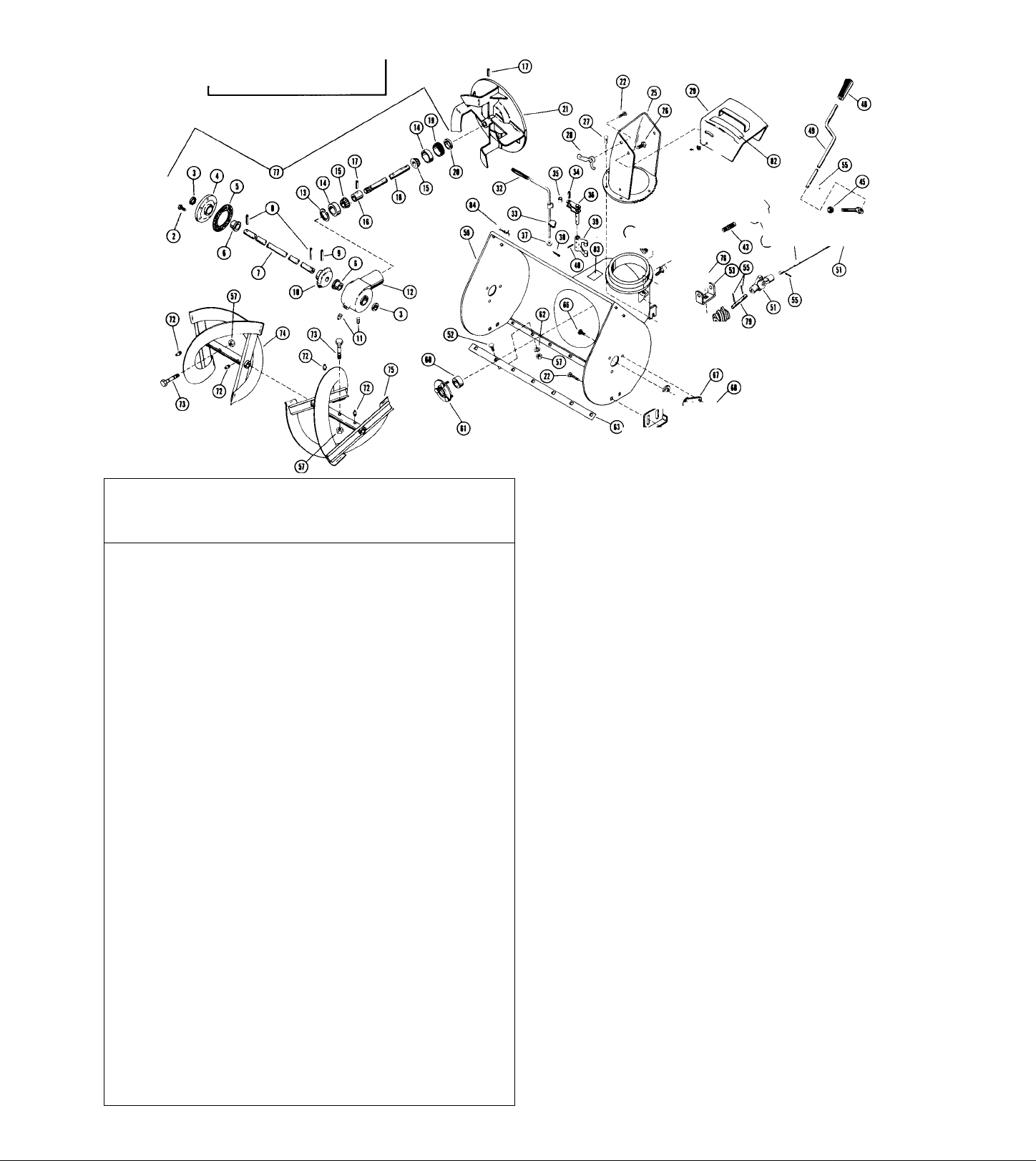
REF
NO.
PART
NO.
DESCRIPTION NO
V >o
§1
» 04
1
2
3
3 10477
4 80012
b 59088
e 10180 R. K. Belt Finger
7
6
e 66018
9
10 72047
10
u
12
13
14
15 63002
16
75006
17
18
10248
19 83015
20
21
22
23
24 10231 Shift Quadrant 1
25
26 mi
27
28 69022 Cap Screw - 5/16-18 UNC x 3/4 Я.Н., Z.P.
29 10464
29
30 67018
31
32
32
33 65040
34 22071 Clutch Handle 1 1
35 59050
36 10465
37
36 10247
39
40
41 10228
42
42
43
44 67001
45 69012 Cable Clamp
46
47
48
49 822010
50 10370
51 58003
52
53 612999
54 70011
59 55030
58 12023 Bearii^ Su^iort 2 2 2 2 2
57 65056
58 10354
59 610938
60 55029
61 83007
62
63 58037
64
65
66 56032 Roll Pin - 3/32 X 1 1
67
68 65054
69
70
71
72
73
74
75 54063
76 10204
77 10267
78 65090
79
80
81
82
83 10473
84
85
88
87
88
89 54074 Thrust Bearing 1 1 1
90
91 3003
92
93
»4
И
Belt Cover Bolt
70013
Outer Belt Guard
10400
10238
84002
66013
63003
72072
10159
2033 Handle Bar Panel 1
10196
59056
10293 Shift Release Handle
10232
69072 Cap Screw - 1/4-20 UNC x 1-1/4 Я.Н., Я.Т.
64037
65042
64043
65070
10463
59062 Cap Screw
69085 Throttle Control
69066
65043
10235
10472
10156
10355
65031
63004
65018
10366
64036
10374 Pin
10372
78038
10375
65041
3031 Bearing Flange
54080
10275
6601S
10205
10471
Engine Sheave
Elaine Sheave
SatBcrew • 5/ie-18 X 3/8 Nirlox
Cap Screw > 5/16-24 UNF x 3/4 H.H., Z.P.
Waeher - 5/16 Wrought Plated
Key - SAE 1035
Key
Lockwasher - 5/16 SAE Std., Plated 8
Belt 1
Belt
Inner Belt Guard 1 1
Handle Bar Washer 2
Cap Screw - 1/4-20 UNC x 1-1/4 H.H., Plated
Lockwasher - 1/4 SAE Std., Plated
Grip
^ftBaU
Spring 1
Shift Handle
Washer - 9/32 LD. x 1-1/4 O.D. x 1/16 Plated 1 1
Locknut - 5/16-18 Hex, Plated 1
Washer - SAE 3/8-13/32 I.D, x 13/16 O.D. x 122 10467
1/16 Plated
Spac^ Bushing 2
Locknut - 1/4-20
Upper Handle Bar 1
Upper Handle Bar 1
Cotter Pin - 1/8 X 1/2
Throttle Control 1
Locknut - 1/4-20 Hex, Plated 7 7 7
Cap Screw - 1/4-20 UNC x 1-1/2 H.H., Plated
Clutch Rod
Locknut - 5/16-24 Hex, Plated 2 2
Ball Joint
Upper Shift Rcxl
Clutch link
Xi>wer Shift Rod
R.H. Lower Handle Bar
R.H. Lower Handle Bar
Nut - 5/16-24, Hex, Plated
Cotter Pin - 3/32 X 3/4 Plated
Lockwasher - 3/8 SAE Std., Plated
Nut - 3/6-16 Hex, PlOed 4 4 4 4 4
Push Nut 1
Universal Joint 1 1
R.H. Axle Shaft 1
Roll Pin - 3/16 X 1-1/4
Washer - .880 I.D. x 1.3880 O.D. x .062
Differential Assembly 1
Ribbed Neck Bolt - 1/4-20 x 5/8 plated 6 6
Bushing 2
Flange 'ЯШг^ск Nut - 1/4-20 Hated 6 6
Zerk Fitting 1
L.H. Axle 1
Roll Pin - 1/4 X 1-3/4 1
LodonitHub 1
Oiffer^tial Lock Decal
Knob
Locknut - 1/2-20 Hex, Centerlock
Locknut - #10-24 Plated 10 10
Ball Bearing
Hex Shaft
Key - Woodruff ¡16
Drive Plate
Ball Bearing
Spindle 1 1
Bearing Housing 1 1
Twin Whizlock Nut
10470 Front Clutch Lever
Rod 1
10237 ’
Sprocket
10276
Disc Bracket
10469
64038
Ш12
Snap Ring
57043
Flange Whizlock Screw 5, 16-18 x 1 2 Plated
70009
Friction Wheel
Friction Disc Hub
10277
Cotter Pin - 1/8 X 1-1/4 Plated
67014
Sprutg
83089
Nut 1/4-20
65032
1 1
1
1 1
2
2
1 1 1
8
1
2 2 2 2
3
2 2 2
1 1
1
1 1
1 1
1 1
1
1
1 1
1 1
1
6 6 6
1 1
1 1
1 1 1
2 2
1
1
2
4 4 4 4
1
8 8
2 2
2
2
1
1
1 1
2 2
1 1
1
1 1
1 1
1 1
1 1
i
2 2 2
! 1
16 16
1 1
1 1
3 1 1
1
. REQ'D
о
Is
ЭО
я
o- о
o> » o>o>
o<»
1
1
1 1 1 1
1 1
2 2
2
2 2 2 2
2
1
8 8 8 8
6
1 1
8 8 6
1
1 1 1
1
1 1 1 X
1 1
2 2 2 2
2 3
1 1
I1X
X
1 1
1 1
1 1
1
1 1 1
1
1 1 1
1
1 1
1
1 X
2 2 2'22
1 1
1 1
1
1
1
1
1
7
1 I
6 6 6 135 58016 RoU Pin - 3/16 X 1 2
1 1 136 10279 Axle Shaft
1 1
2 2 2
1
1
2 2
1
8 8 6
1
1 1
6
6
2 2
6
6 6 6
2
1
1
1
1
10
10 10 10
2
2 2
2 2
2 2
1
1
2
1
1
1
1 I /
1
U''
■ 2 2
1 1
18 18 18
18
1
1
1
PART
REF
NO. NO.
<o
to
я
8
1
96 70032
1
97 10161 L.H. Belt Finger
98
1
1
99
2
2
xoo
lOi
1
X
X02
103
104
1
1
105 65015 Nut - 5/16 -18 Hex, Plated
8
8
106
107 10479
108
X09
1
X
109 10356
2 110
2
111
3
112
2
2
113 59073
1
IH 10361
X
XX5
1
1
lie
X
1X7 10239
X
118
119 67001
120
1
121 67019 Hair Pin Cotter
X X23 59001 Cap Screw 1/4-20 x 3/4 X
124 64056
1
X25
X
126 10215
1
127 10476 Transfer Lever
1
1
128 10484 Connecting Link
129
1
130 55040
1
131
X32 64033
1
7
133 66011
7
134 66012 Key - WoodnSEC #91
1
137 59074
2
138
139 10211
140 10208
2
141
X
X42
143
1
143 10459 Tractor Frame
2
144 3376
4
145
1
146 10466 Rear Clutch Lever
6
147
4
148
X
149
1
150 10481 Clutch Interlock Lever
1
151 22073
1
152 22074 U Bolt
153
1
154
6
6
2
155 610985 Tire and Wheel Ass^bly
1
1
1
1
X
156 612991
1
1
1
2
2
157
1
158
Wheel Bolt - 1/2-20
10482
Clutch Handle
75013
Grip
Wheel Hub
X0283
10492
Belt finger 1
84007
Washer
83004 Spring
5503Э
Flange Bushing
10360
Bearing Spacer
Clutch Bracket
12086 Cap
i0l57 L.H. Lower Handle Bar
L.H, Lower Handle Bar
12X32 Idler
59069
Cap Screw - 5/16-18 UNC x 1-1/4 H.H., Plated
10389
Idler Arm
Cap Screw - 5/16-18 UNC x 1-3/4 H.H., Plated
Shoulder Spacer
64057
Wither
10206
Jaw СоцрНвв
Driven Sheave
10460
Bottom Cover
Hair Pin
59023
Cap Screw - 3/8-16 UNC x 3/4 H.H., Plated
Fork Shaft
Washer
10X44 Clevis Pin 1 X
Lever Bracket 1 1
3086 Ball Joint
Bushli^
10461 SlidUig Fork
Washer - .755 LD. x 1.375 O.D. z.125 Plated
Key
Cap Screw - 5/16-18 UNC x 2-3/4 H.H., Plated 1 1
10462
Support Bracket 1 1
Spur Gear
Ptnitm Stub Shaft
55026
Bushing
10207
Pinion and Sprodcet
10458 Tractor Frame
Spindle Cup
3377
Hub Cap
10468 Pivoi ^»cer
64038
Washer .505 LD. x .686 aD. x 24 Ga.
10483 Rod Hanger Bracket
Handle Pivot
10480
Engagement Rod
58034
Roll Pin
consistii« of: Req’d per Wheel 2
71046 Tire (Carlisle Stud Tread
Tire and Wheel Assembly
consisting of: Req'd per Wheel
71066 Tire (Carlisle Stud Tread
71050 Tube 1
67004
Cotter Pin 1/8 X 1 Plated
Hair Pin Cotter
67010
1
•6 HP Engine (Tecumseh HSK-60 7536U)
2
1
1
1
1
1
1
1
1
1
1
•7 HP Engine (Tecumseh НЖ-70 130067A)
/
•8 HP Engine (Tecumseh HSK-80 15S020)
*Order Replacement Engine
And/Or Ekigine Replacement ^
Parts From Your Nearest
Engtoe Service CentraL
10373
Carburetor Cover
78010
Helicon Patent Label
78189
Air Cleaner Decal
78016
Sno Shift Label
78231
Engine Label
78191
Engine Decal - 8 Ч. P. (91009 910010 910016 910018)
78192
Engine Decal - 7 H, P. (910007 910008 910014)
78230
Label - In-Out
78225
Engine Decal - 6 H. P, (910006)
75040
Plug
DESCRIPTION
TIRES AND WHEEL ASSEMBLIES
Tire Available OiUiy) 1
71050 Tube 1
71052 Rim 1
Available Only) 1
71052 Rim 1
NOT ILLUSTRATED
or Replacement
or Replacem«it
or Replacement
NO. REQ’D
o-_
о
0<N
Oo
oo
si
6
2 2
vl
2
6
1
3
1
1
1
2
444
2
».»
o>o>
6 6
I I
1 1
1 1
t
1
1
6 6
1 1
1 1
3 3
1 1
1 X
1 1
1 1
1 1
1 1
1 1
1 X
1 X 1
1
1 X
2 2
2 2
1 1
X 1 1
1
1 1
1 1
1 1
2 2
1 X
s•o8 s
o>
»
6 8 6
1 1
1 1
1
1
1 1
X *
2
6 6
1 1 1
1 1
333
X 1
1 1
1 1
1 X
1 1
1 1
1 2
1
1 1
222
4 4 4
2 2 2
1
X 1
X 1
1 1
1 1
1 1
X 1
222
i 1
2 г
1 X
1 1
1
2
2 2 2 t 8
11X 1 1
1
2
2 1
2
1 1
X 1
1 1
X
X X
1
1 1
1 1
1 1
3 3 3
2
1
1 1
1
1 1 X
1
X 2 1
X
1
X 1 1
1
1 1 1
1
1
1 1
3
2 2
2
2 212
2I2
1
1
X I 1
1
1 1
1 1
1 1
1
1 1 1
1 1
1 1
1
1
1
1
1 1
1 1
1
1
Os
1
t
1
6
1
1
1
1
1
1
1
1
1
3
2
1
1
1
1
1
Page 9
Page 10
Page 11

REF. PART
NO. NO.
DESCRIPTION
NO. REQ’D .
REF. PART
NO. NO.
DESCRIPTION
NO. REQ’D .
/
F
Y
70013 Belt Cover Bolt 1 1 1
l
10400 Outer Belt Guard
2
10238 Engine Sheave 1 1 1
3
4
60012 Setscrew - 5/16-18 x 3/8 Nylok 2 2 2
Cap Screw - 5/16-24 UNF x 3/4 H.H., Z.P. 2 2 2
59053
5
6
7 64002
8
9
10
11
12 2033
13 10196
14
15 63002
16 75006
17 10293
18
19 83015 Spring
20 10232
21
22
23 65042
24
25 64043
26 6071 Spacer Bushing
27 65070 Locknut - 1/4-20
28 59022 Cap Screw - 5/16-18 UNC x 3/4 H.H., Z.P.
29 10357 Upper Handle Bar
29
30
31
32
33
34
35
36
37
38
39
41 10226 Lower Shift Rod
42 10156 R. H. Lower Handle Bar
42 10355 R. H. Lower Handle Bar
43 65031
44 67001 Cotter Pin - 3/32 X 3/4 Plated
45 69012 Cable Clamp
46
47 65018 Nut - 3/8-16 Hex, Plated
48 10366 Push Nut
49
50 10370 R. H. Axle Shaft
51
52 64036 Washer - .880 LD. x 1,3880 O.D. x .062
53 612999 Differential Assembly 1 1
54 70011 Ribbed Neck Bolt - 1/4-20 x 5/8 Plated
55 55030 Bushing
56
57
56 10354 Zerk Fitting 1 1
59 610938
60 55029
61
62 10374
63
64 10372 Lockout Hub
65 78038 Differential Lock Decal
66 58032
67
68 65054
69
70 3031
71 54080
72
73 66015
74 10205
75
76 10204
77 10267
78 10226
79 10227
80
81 10237
82
R. H. Belt Finger
10160
Washer - 5/16 Wrought Plated
Key - SAE 1035
66013
Lockwasher - 5/16 SAE Std., Plated
63003
72047 Belt
Inner Belt Guard
10159
Handle Bar Panel
Handle Bar Washer
Cap Screw - 1/4-20 UNC x 1-1/4 H.H., Plated
59056
Lockwasher - 1/4 SAE Std., Plated
Grip
Shift Release Handle
10248 Shift Ball
Shut Handle
Cap Screw - 1/4-20 UNC x 1-1/4 H.H., H.T.
59072
64037 Washer - 9/32 I.D. x 1-1/4 O.D. x 1/16 Plated
Locknut - 5/16-18 Hex, Plated
Shift Quadrant
10231
Washer - SAE 3/8-13/32 I.D. x 13/16 O.D. x
1/16 Plated
10241 Upper Handle Bar
67004 Cotter Pin - 1/8 X 1 Plated
74001 Self-Tappii^ Screw - #10-12 x 1/2 Pan Head
69032
Throttle Control
65040
Locknut - 1/4-20 Hex, Plated
2038 Clutch Handle
59050
Cap Screw - 1/4-20 UNC x 1-1/2 H.H., Plated
10230
Clutch Rod
65043
Locknut - 5/16-24 Hex, Plated
10247 Ball Joint
10235 Shut Rod
Nut - 5/16-24 Hex, Plated
63004 Lockwasher - 3/8 SAE Std., Plated 8
64042 Washer - .761/.757 I.D. x 2 O.D. x 1/8
58003 Roll Pin - 3/16 X 1-1/4
12023
Bearing Support
65056 Flange Whizlock Nut - 1/4-20 Plated 6
L. H, Axle
Bushing
83007
Spring 1 1
Pin 1 1
58037
Roll Pin - 1/4 X 1-3/4 1 1
RoU Pin - 3/32 X 1
10375
Knob
Locknut - 1/2-20 Hex, Centerlock
65041
Locknut - #10-24 Plated
Bearing Flar^e
BaU Bearii^
10275 Hex Shaft
Key - Woodruff #5
Drive Plate
54063
BaU Bearing
Spindle
Bearing Housii^
Neutral Catch
Throwout Lever
10358
Spacer Bushing
Chain
10276 Sprocket
FOR OFFSET AND CONNECTING
LINKS FOR 10237 CHAIN, ORDER
BY THE FOLLOW ING PART
NUMBERS:
#39 - OFFSET LINK
#41 - CONNECTING LINK
1
1
10 101010 10
1 1
9
1
1 1
1
2
2 2
4
2
1 1 1 1 1
1
1 1 1 1 1
1 1 1
1 1
1 1 1 1 1
2 2
1 1 1 1 1
1 1 1 1 1 106
1 1
1 1 1 1 1 108
2 2
1
2
2
1
6
1
5
1
2
1
1
1
1
2 2 2
2 2 2
1 1 1
4
2
6 6 6 6 6
2
---------
ORDER PARTS BY PART NUMBER
NOT BY REF. NUMBER. ANY PART
ORDERED BY REF. NUMBER WILL
BE DISREGARDED.
F
1 1
1 1
1
1
2
2
1
1
1
1
1
9 9 9 9
1 1
1
1
1 1
1 1
1
2 2 2 2
2
2
4 4 4 4
2
2
2 2
1 1
1
1 1
1
1
2
2 2 103
1
1
2
2 2 109
1 1 1 ^09
1
2 2
2
2 2
2
1
1
1 1
6 6
6 6
1 1
1
5 5
5 5
1 1
1 1
2 2
2 2
1 1 1 1
1 1
1 1
1
1
1 1 122
1
1
1
2
2 2
1 1
8
8
8
4 4 4 4
1 1 1
2 1
1
1 1
1
1
1
1 1
2 2 2
2 2
2
6 6 6 6
1
1
2
2
1 t
1 1 1
1 1
1
2 2
2
8
2
2
1
1
1 1 1 1 1
2 2 2 2 2
1 1 1 1 1
1 I
1
1 1 1 1
1
1
1 1
2
8 8 8 8
2 2
2
2 2
2 2
1 1 1
1 1
1 1
1 1 1
1
1
1 1
1 1
1 1
1
1 1
CMnOif
7"
F(
83 10222
1
84 10240
1
85
2
2
1
1
1
1
2
1
1 101
1 107
2
2
1
1
2
8
1
1
1
2
1
2
1
2
2
64038
86 10212
87
3085
88 57043
89
54074
90
70009
91
3003
92
10277
93
67014
94
83058
95
10266
96
70005
97
10161
10362
98
99 75005
100
10283
59003
102
11031
83004
104
55039
105
65015
10360
10363
12086
10157
10356
no
12132
111
59069
112
10389
113
59073
114
10361
116
10206
117
10239
118
10147
119
59028
120
59023
121
67010
10394
123
10382
124
74021
125
10144
126 10215
127 10217
128 10285
129
3086
130
55040
131 10213
64064
132
133
66011
134 66012
135
136
137 59074
138 10209
139
140 10206
141
142
143 10391
144
146
610985
147
612991
-------------
Disc Bracket
Spacer
Shim Washer - .505 LD, x .880 O.D. x 2^ Ga.
Bracket Pin
Bearing Flange
Snap Ring
Thrust Bearii^
Flange Whizlock Screw - 5/16-18 x 1/2 Plated
Friction Wheel
Friction Disc Hub
Cotter Pin - 1/8 X 1-1/4 Plated
Spring
Hub Cap
Wheel Bolt - 1/2-20
L. H. Belt Finger
Clutch Lever
Grip
Wheel Hub
Cap Screw - 5/16-18 UNC x 1 H.H., Plated
Spacer
Spring
Flai^e Bushing
Nut - 5/16-18 Hex, Plated
Bearing Spacer
Clutch Bracket
Cap
L. H, Lower Handle Bar
L. H. Lower Handle Bar
Idler
Cap Screw - 5/16-18 UNC x 1-1/4 H.H., Plated
Idler Arm
Cap Screw - 5/16-18 UNC x 1-3/4 H.H., Plated
Shoulder Spacer
Jaw Couplii^
Driven Sheave
Bottom Cover
Cap Screw - 1/4-20 UNC x 1/2 H.H., Plated
Cap Screw - 3/8-16 UNC x 3/4 H.H., Plated
Hair Pin Cotter
Fork Shaft
Cover
TapUte - #10-24 x 1/4
Clevis Pin
Lever Bracket
Transfer Lever
Connecting Link
Ball Joint
Bushing
Sliding Fork
Washer - .755 LD. x 1.375 O.D, x .125 Plated
Key
Key - Woodruff #91
56016
RoU Pin - 3/16 X I
10279
Axle Shaft
Cap Screw - 5/16-18 UNC x 2-3/4 H.H., Plated
Support Bracket
10211
Spur Gear
Pinion Stub Shaft
55026
Bushing
10207
Pinion and Sprocket
Tractor Frame
10373
Carburetor Cover (Not Ulus.)
78010
Helicon Patent Label (Not Ulus.)
78011
Clutch Label (Not Ulus.)
78013
Carburetor Cover Decal (Not Ulus.)
78016
Sno Shift Label (Not Ulus.)
78034
Engine Decal - 5 H.P. (Not Ulus.)
78035
Engine Decal - 6 H.P. (Not Ulus.)
Engine Decal - 7 H.P, (Not Ulus,)
Spindle Cup
Hub Cap
TIRE AND WHEEL ASSEMBLIES
Tire and Wheel Assembly
consisting of: Req'd. per Wheel
71046 Tire (Carlisle) 1
71049 Tire (Goodyear) 1
71050 Tube 1
71052 Rim 1
Tire and Wheel Assembly
71066 Tire 1
71050 Tube 1
78148
78149
71052 Rim 1
Engine Label (Not Ulus.)
Wheel Drive Decal (Not Ulus.)
OR
consisting of: Req'd. per Wheel
1 1 1 1
OR OR
2 2 2 2
2 2
2
1 1
3
1
1 1
2 1 I
6 6
6
1
1
1
1
1 1 1 1
2
1 1 1 1
1 1
1
1 1
7 7
1
1 1 1
1
1
1 1 1 1
2 2 2 2
4
4
1 1 1 1
1 1
2 2
4 4 4 4
1 1
1 1 1 1
1
1
1 1 1 1
2
1
2
1
1 1
1 1
1
1 1
2 2
1 1
1 1
1
1 1
1 1
1
1 1 1
1
2 2
2
1
1
1
moTi
1 1
1 1
1 1
1 1
1
7
1 1
1
1 1
1 1
1
4 4
1 1
2 2
1
1 1
1 1
2 2
1 1
1 1
1 I
2 2
1 1
1 1
1 1
1 1
1 1
1 1
1 1
1 1
1 1
2
1 1
1 1
OR
14
1 1 1
1
OR OR
2
1 1 1 1
2
1 1 1 1
1 1 1 1
141414 14
1
1 1 1 1
3
1
2
6
1
1
1
2
1
1
1
2 2
7
1 1 1 1 1
1 1
1 1 1
1 1
1 1 1
1 1 1
1 1 1 1 1
1
1 1 1 1 1
1
1 1 1 1 1
1 1 1 1 1
2
4
1
1
2
4
1
1 1 1 1 1
1 1 1
1
1
2 2 2
1
1 1
2
1
2
1
1
1
1
1
2
1
1
1 1 1
1
1 1 1
1
1
2 1
2
2
1
1 1
THE 3376 SPINDLE CUP AND 3377
HUB CAP ARE USED ON MODELS
AFTER SERIAL NUMBERS LISTED
910002 - 000001
910942 - 000625
910954 - 004800
910962 - 021500
1
2
1
1
1
1
1
1
6
1
1
7
1
1
1
Page 11
Page 12
ORDER PARTS BY PART NUMBER
NOT BY REFERENCE NUMBER" ANY
PART ORDERED BY REFERENCE
NUMBER WILL BE DISREGARDED.
#
REF.
PART
NO.
NO.
64046
1
2 70012
3 56061
4 10181
10108
5
6 55035
7 10384
7 10299
58030 Roll Pin 3/16 X 1-1/2
8
9 58022 Roll Pin 5/16 X 1-3/8 1 1
10 10183
11 1138
12 10180
13 57032 Snap Ring
14 54044 Bearing Cup 2
15 54045
16 10107
17 58007 Roll Pin 1/4 X 1-1/4 3
10177 Helicon Pinion Shaft
18
19 10371 Adjustment Plug
20 56062 Seal
21 10178 Fan
22 62010 Carriage Bolt 3/8-16 x 3/4
23 10393 Safety Wire
24 22122
25 10437 Discharge Chu':e
26 59023
27 74026 Taptite #10-24 x 3/8
28 10193 Wing Nut
29 10191
30 65039 Locknut 3/8-16
31 63004
32 75004 Grip 1/2 ID
10390
33
34 58017
35 3034 Roller
36 10186
37
10260
67004
38
39
1008
40 58016 Roll Pin 3/16x1
41 70010 Flange Whizlock Screw 3/8-16 x 1/2
42 10176 Jaw Clutch
43 83014 Spring
44
64048 Washer 1.376 OD x .755 ID x 1/16
45 65040 Locknut 1/4-20
46 10142 Bearing Flange
Washer 1.505 OD x 1.005 ID x 1/16 4 4
Flai^e Whizlock Screw 1/4-20 x 3/4 5 5 48 10197
Seal 2
Gear Case Flange 1 1
Gasket 1 1
Bushing 4 4 .385
Front Gear Shaft
Front Gear Shaft
Helicon Gear
Pipe Plug 3/8 Sq. Hd, 2 2
Gear Case
Bearing Cone 2 2
Bearing Spacer
Fastener
Cap Screw 3/8-16 x 3/4 H.H. 2 2 70
Deflector 1 1
Lockwasher 3/8
Fork Cam
Roll Pin 5/16 X 1-1/4
Fork Shaft
Wave Washer
DESCRIPTION
NO. REQ'D
1
2 2
1 1
1 1
1 1
1 1
1 1 63
1 1 63
1 1 64
1
5 5
1 1 67
2 2
1 1 69 64047
6 6 71
1 1
6 6 74 10433
2 2
1
1
1 1
1 1
1 1
111
1 1
2 2
2
1 1
1
1 1
4 4
1 1
REF
PART
NO.
NO.
47
10198 Cap
2 49
1 52
2
3
1 65
1 75 10434
1
1
2
1
10439 Chute Control Crank
50 10289 Rod Hanger
51 64052
62026 Carriage Bolt 5/16-18 x 5/8 5
53 22123
54
22110 Worm Gear
55
58034 Roll Pin 1/8 X 3/4
56 64007
57
65042
58 10438
59
10388
59
10179
60
54063
61
3017
62 64002
10387
10164
10442
10165 Runner
66 70011
10184
68
65056
63006
59024
72
10354
73
10195
74
10431
75
10432
62011
76
77
510002
77
610984
78012
78014 Caution Label
78055 Clutch Instruction Decal
DESCRIPTION
Grip
Washer 13/16 OD x .380 ID x 24 Ga.
Worm Clevis
Washer 1/4 Std.
Locknut 5/16-18
Chute Clamp
Blower Housing
Blower Housing
Ball Bearing
Bearing Flange
Washer 5/16
Scraper Blade
Scraper Blade
Reinforcement Angle
Ribbed Neck Bolt 1/4-20 x 5/8
Bearing Support
Whizlock Nut 1/4-20
Washer 1.441 OD x .511 ID x 1/8
Lockwasher 1/2
Cap Screw 1/2-13 x 1 H.H.
Zerk Fitting
Shear Bolt
R. H. Rake
R. H. Rake
L. H. Rake
L. H. Rake
Carriage Bolt 5/16-18 x 3/4
Gear Case Assembly
Gear Case Assembly
NOT ILLUSTRATED
Sno-Thro Label
NO.
1
1 1
1 1
1 1
1 1
1 1
1 1
1 1
1 1
8
3
1
1 1
1 1
9
1
2 2
6 6
2
6
2 2
2 2
2
4
2 2
1
1
1 8
1
1 1
1 1
1 1
REQ'D
V
/
1
#
10
3
1
4
1
1
2
6
2
4
1
1
Page 12
Page 13
10997SLICER BAR KIT
24" SNO-THRO MODEL 10995
1
-----
58007
I0I78
0354
64046
r ^ ^ i
10181 /
-------------------
55035
r ■ ”■
Part
No.
10108
58030
10299^^^<i>
58022
Description
58007-
54(m ^
V
^ 54045 ^ 580,7'
■-1 ^ \
10177 75004
No.
Req’d.
'^56062 V| 10193-
10371
Part
No.
64002 /
65039 63006
Desci-iption
63004
65039 ^
k J
----------^>64007
^65042
No.
Req'd.
22110
58034
1008
1138
3017
3034
10107 Bearing Spacer
10108
10142
10164
10165
10176 Jaw Clutch
10177 Helicon Pinion Shaft
10178
10179
10180
10181
10183
10184
10186
10191
10193
10195
10197
10198
10260
10289
10299
10354
10371 Adjustment Plug
10390
10393
10431 R. H. Rake
10432 L. H. Rake
10437 Discharge Chute
10438
10439
22110
22122
22123
54044
54045
54063
55035
56061
Clutch Fork
Pipe Plug 3/8 Sq. Hd.
Bearing Flange
Roller
Gasket
Bearing Flange
Scraper Blade
Runner
Fan
Blower Housing
Gear Case
Gear Case Flange
Helicon Gear
Bearing Support
Fork Shaft
Deflector
Wing Nut
Shear Bolt
Grip
Cap
Wave Washer 1
Rod Hanger
Front Gear Shaft 1
Zerk Fitting
Fork Cam
Safety Wire 1
Chute Clamp
Chute Control Crank 1
Worm Gear
Fastener 2
Worm Clevis
Bearing Cup
Bearing Cone 2
Ball Bearing
Bushing
Seal
1
2
1
1
1
1
1
1
2
1
1
1
1
1
1
1
2
1
1 64048
1 64052
2
1 65039
1
1 65056
4
1
1
1
1
1
3
1
1
2
1
4
2
56062
57032 Snap Ring
58007
58016
58017
58022
58030
58034
59023
59024
62009
62010
63004
63006
64002
64007
64046
64047
65040
65042
67004
70010
70011
70012
74026
75004
83014
78012
78014
78055
10242 Sheer Bar
62009
65042
Seal 1
Roll Pin 1/4 X 1-1/4
Roll Pin 3/16 X
Roll Pin 5/16 X 1-1/4
Roll Pin 5/16 X 1-3/8
Roll Pin 3/16 X 1-1/2
Roll Pin 1/8 X 3/4
Cap Screw 3/8-16 x 3/4 H.H.
Cap Screw 1/2-13 x 1 H.H,
Carriage Bolt 5/16-18 x 1/2
Carriage Bolt 3/8-16 x 3/4
Lockwasher 3/8
Lockwasher 1/2
Washer 5/16
Washer 1/4 Std.
Washer 1,505 OD x 1.005 ID x 1/16
Washer 1.441 OD x .511 ID x 1/8
Washer 1.375 OD x ,755 ID x 1/16
Washer 13/16 OD x .380 ID x 24 Ga.
Locknut 3/8-16
Locknut 1/4-20
Locknut 5/16-18
Whizlock Nut 1/4-20
Cotter Pin 1/8 X 1
Flange Whizlock Screw 3/8-16 x 1/2
Ribbed Neck Bolt 1/4-20 x 5/8
Flange Whizlock Screw 1/4-20 x 3/4
Taptite #10-24 x 3/8
Grip 1/2 ID
Spring
Sno-Thro Label
Caution Label
Clutch Instruction Decal
Carriage Bolt 5/16-18 x 1/2
Locknut 5/16-18
1
.385
NOT ILLUSTRATED
10997 SLICER BAR KIT
1
3
2
1
1
2
1
2
2
6
5
2
2
9
1
4
2
1
1
6
4
8
6
1
2
6
5
6
1
1
1
1
1
1
2
2
Page 13
Page 14
MODEL 10965 40962,10954 & 10942
59053
10)60
TRACTOR ONLY
Il >
Page 15
MODEL 10965 Л 0962,10954 & 10942
TRACTOR ONLY
Part
No.
2033 Handle Bar Panel
2038
2045
3003 Friction Wheel
3031 Bearing Flange
3085
3086
6071
10144
10147 Bottom Cover
10156
10157
10159
10160
10161
10196
10204
10205
10206
10207
10208
10209
10211
10212
10213 Sliding Fork
10215
10217
10222
10226
10227
10228
10230 Clutch Rod
10231
10232 Shift Handle
10235
10237 Chain
10238
10239 Driven Sheave
10240
10241
10247
10248
10250
10267
10275
10276
10277
10279 Axle Shaft
10283 Wheel Hub
10285
10288
10293 Shift Release Handle
10354
10355
10356 L, H. Lower Handle Bar
10357 Upper Handle Bar
10358 Spacer Bushing
10360
10361 Shoulder Spacer
10362 Clutch Lever
10363 Clutch Bracket
10366 Push Nut
10369
10370 R. H. Axle Shaft 1 1 1
10372 Lockout Hub
10373
10374 Pin
10375 Knob
10362
10389 Idler Arm
10391 Tractor Frame
10394 Fork Shaft
10400
11031 Spacer
12023 Bearing Support
12086
12132 Idler 1 1 1 1
A12999
54063
54074
54080
55026
55029
55030
55039
Clutch Handle
Clutch Lock Pin
Bearing Flange
Ball Joint
Spacer Bushing
Clevis Pin
R. H. Lower Handle Bar
L. H. Lower Handle Bar
Inner Belt Guard
R. H. Belt Finger
L. H. Belt Finger
Handle Bar Washer
Drive Plate
Jaw Coupling
Pinion and Sprocket
Pinion Stub Shaft
Support Bracket
Bracket Pin
Lever Bracket
Transfer Lever
Disc Bracket
Neutral Catch
Throwout Lever
Lower Shift Rod
Shift Quadrant
Shift Rod
Ermine Sheave
Spacer
Upper Handle Bar
Ball Joint
Shift Ball
Cover
Bearing Housing
Hex Shaft
Sprocket
Friction Disc Hub
Connecting Link
Hub Cap
Zerk Fitting
R. Hi Lower Handle Bar 1
Bearing Spacer
L, H. Axle
Carburetor Cover (Not Illus.)
Cover
Outer Belt Guard
Cap
Differential Assembly
Ball Bearing 2
Thrust Bearing
Ball Bearing
Bushing 2 2
Bushing
Bushing 2
Flange Bushii^ 2
Description
No.
Req'd.
1 1 1 1
1 1 1 57037 Retaining Ring
1
1 1
1 1
1 1
1 1
2 2 2
2 2 2
1 1
1 1
1 1 59003
1 1
1 1
1 1
1 1 1 1 59023
1
1 59050
1 1 1 1 59053
1 1 1 1 59056
1 1 1 59069
1
2 2 2
1 1 59073
1 1
1 1 59074
1 1
1 1 1
1 1 1
1 1
1 1
1 1 1
1
1 1 1
1
1 1 1 1
1 1 1 1
1 1 1
1 1
1 1
1
1
1 1
1 1 65040
1 1 65041 Locknut - #10-24 Plated
1
1 1
1 1 67001
1 1 67004
1 1 67010 Hair Pin Cotter
1 67014
2 69012 Cable Clamp
1
2
1 1
1 1 1 72047 Belt
1 1 1 74001
1 1 1 1
1 1 1 1
1 1 1 1
1 1 1 1
1 1 1 1
1 1 1
1 1 1
1 1 1
1 1 1
1
1
2
2
1
1
1 1 1 1
1 1
1 1 1 1
1 1 1 1
2 2 2 2
1
1
1 1
2 2 2
1
1 1 1
2 2 2
2 2
Part
No.
/
55040
57043
2
2
2
1 60012
1 63002
1
1
1 1/16 Plated
1
1 65031
1
1
1
1
1 66012
1
1
1
1
1
1 1
1 1
2 2
1
1
1
1
1 1
1
2
2 2
2
2 2
58003
58007
58016 RoU Pin - 3/16 X 1
58032
59022
59028
59072
63003
63004
64002
64033
64036
64037
64038
64042
64043
65015
65018 Nut - 3/8-16 Hex, Plated
65042
65043 Locknut - 5/16-24 Hex, Plated
65054 Locknut - 1/2-20 Hex, Centerlock
65056
66011 Key
66013 Key - SAE 1035
66015 Key - Woodruff #5
69032
70005 Wheel Bolt - 1/2-20
70009
70011
70013 Belt Cover Bolt
74021
75005
75006
78010 Helicon Patent Label (Not Illus.)
78011
78013
78016
78034
78037
78038
83004 Spring
83007 Spring
83015
A10985
A12991
Bushing
Snap Rii^
Boll Pin - 3/16 X 1-1/4 1 1 1
RoU Pin - 1/4 X 1-1/4 1 1 1
RoU Pin - 3/32 X 1 1 1 1
Cap Screw - 6/16-18 UNC x 1 H.H., Plated
Cap Screw - 5/16-18 UNC x 3/4 H.H., Z.P.
Cap Screw - 3/8-16 UNC x 3/4 H.H., Plated
Cap Screw - 1/4-20 UNC x 1/2 H.H., Plated
Cap Screw - 1/4-20 UNC x 1-1/2 H.H., Plated
Cap Screw - 5/16-24 UNF x 3/4 H.H., Z.P.
Cap Screw - 1/4-20 UNC x 1-1/4 H.H., Plated
Cap Screw - 6/16-18 UNC x 1-1^ H.H., Plated 1 1
Cap Screw - 1/4-20 UNC x 1-1/4 H.H., H.T.
Cap Screw - 5/16-18 UNC x 1-3/4 H.H., Plated
Cap Screw - 5/16-18 UNC x 2-3/4 H.H., Plated
Setscrew - 5/16-18 x 3/8 Nylock
Lockwasher - 1/4 SAE Std., Plated 4 4
Lockwasher - 5/16 SAE Std., Plated
Lockwasher - 3/8 SAE Std., Plated 8 8 8
Washer - 5/16 Wrought Plated
Washer - ,755 LD. x 1.375 O.D. x .125 Plated 1
Washer - .880 I.D. x 1.380 O.D. x .062 1 1
Washer - 9/32 LD. x 1-1/4 O.D. x 1/16 Plated
Shim Washer - .505 I.D, x .880 O.D. x 24 Ga.
Washer - .751/.757 I.D. x 2 O.D. x 1/8
Washer - SAE 3/8-13/32 LD. x 13/16 O.D. x
Nut - 5/16-18 Hex, Plated
Nut - 5/16-24 Hex, Plated
Locknut - 1/4-20 Hex, Plated
Locknut - 5/16-18 Hex, Plated
Flange Whizlock Nut - 1/4-20 Plated
Key - Woodruff #91
Cotter Pin - 3/32 X 3/4 Plated
Cotter Pin - 1/8 X 1 Plated
Cotter Pin - 1/8 X 1-1/4 Plated
Throttle Control
Flai^e Whizlock Screw - 5/16-18 x 1/2 Plated
Ribbed Neck Bolt - 1/4-20 x 5/8 Platisd
Self-Tapping Screw - #10-12 x 1/2 Pan Head
Taptite - #10-24 x 1/4
Grip
Grip
Clutch Label (Not Illustrated)
Carburetor Cover Decal (Not Illus.)
Sno Shift Label (Not Illustrated)
Engine Decal - 5 H.P. (Not Illus.)
Engine Decal - 7 H.P. (Not Illus.)
Differential Lock Decal
Spring
TIRE AND WHEEL ASSEMBLIES
Tire and Wheel Assembly
71046 Tire (Carlisle) 1
71049 Tire (Goodyear) l
71050 Tube 1
71052 Rim i
Tire and Wheel Assembly
Description
consisting of: Req’d. per Wheel
OR
consisting of: Req'd, per Wheel
71066 Tire 1
71050 Tube 1
71052 Rim 1
No.
Req’d.
И
2
2 2 2
1 1 1 1
1
1 1 1
2
1 1 1
2 2 2
4 4
4
2
2 2
5 5 5
2
2 2
2 2 2
1
1 1 1
1 1 1
1 1 1
2 2
2
4
9 9 9
10
10 10
1
1 1
1
1
1
OR
OR
OR
2
2
2
2
1 1 1
1 1 1
7 7 7
4 4 4 4
2 2 2 2
7 7 7
8 8 8
2 2 2 2
2 2 2 2
2 2 2 2
6 6 6 6
2
1
1 1
1
1 1
1 1
2 2 2
2 2 2
1 1 1
3
1 1
1
1 1
1 1 1
6 6 6 6
14 14 14 14
6
6 6 6
1 1 1
1 1
1 1
3 3 3 3
4
4 4
1 1 1
2 2 2 2
1 1 1 1
1 1
1 1 1
1 1 1
1
1 1
1 1
2 2 2 2
2 2 2
1 1
2
2
2
1
2
4
2
5
2
2
1
1
1
1
2
4
9
8
10
1
1
1
OR
2
1
7
7
8
1
2
2
1
1
1
1
1
4
1
1
2
#
Page 15
Page 16

10997 SLICER BAR KIT
32” SNO-THRO MODEL 10955
Part
No.
1008
1138
3017 Bearing Flange
3034
10107 Bearing Spacer
10108
10142 Bearing Flange
10165
10176 Jaw Clutch
10177 Helicon Pinion Shaft
10178
10180 Gear Case
10181 Gear Case Flange
10183 Helicon Gear
10184
10186 Fork Shaft
10191
10193 Wing Nut
10195
10197 Grip
10198 Cap
10260
10289 Rod Hanger
10354
10371 Adjustment Plug
10384 Front Gear Shaft
10387
10388 Blower Housing
10390 Fork Cam
10393 Safety Wire
10433 R. H. Rake
10434
10437
10438 Chute Clamp
10439 Chute Control Crank
10442 Reinforcement Angle
22110
22122 Fastener
22123 Worm Clevis
54044 Bearing Cup
54045
54063 Ball Bearing
55035 Bushing
56061
Clutch Fork
Pipe Plug 3/8 Sq. Hd.
Roller
Gasket
Runner
Fan
Bearing Support
Deflector
Shear Bolt
Wave Washer
Zerk Fitting
Scraper Blade
L. H. Rake
Discharge Chute
Worm Gear
Bearing Cone
Seal
Description
No.
Req'd.
1
2
1
1
1 58017 Roll Pin 6/16 X 1-1/4
1 58022
1 58030 Roll Pin 3/16 X 1-1/2
2
1 59023 Cap Screw 3/8-16 x 3/4 H.H.
1 59024 Cap Screw 1/2-13 x 1 H.H.
1 62009 Carriage Bolt 5/16-18 x 1/2
1 62010 Carriage Bolt 3/8-16 x 3/4
1 62011
1 63004
2
1
1 64007
1 64046
2 64047
1 64048
1
1
1
4
1
1
1
1
1
1
1
1
1
3
1
1
1
2
1
2
2
1
4
2
Part
No.
56062 Seal 1
57032
58007 Roll Pin 1/4 X 1-1/4
58016
58034 Roll Pin 1/8 X 3/4
63006 Lockwasher 1/2
64002 Washer 5/16
64052
65039
65040
65042
65056
67004
70010
70011
70012
74026
75004
83014
78012
78014
78055
10242
62009
65042
Snap Ring
Roll Pin 3/16 X 1
Roll Pin 5/16 X 1-3/8
Carriage Bolt 5/16-18 x 3/4
Lockwasher 3/8
Washer 1/4 Std.
Washer 1.505 OD x 1.005 ID x 1/16
Washer 1.441 OD x .511 ID x 1/8
Washer 1.375 OD x .755 ID x 1/16
Washer 13/16 OD x .380 ID x 24 Ga.
Locknut 3/8-16
Locknut 1/4-20
Locknut 5/16-18
Whizlock Nut 1/4-20
Cotter Pin 1/8 X 1
Flange Whizlock Screw 3/8-16 x 1/2
Ribbed Neck Bolt 1/4-20 x 5/8
Flange Whizlock Screw 1/4-20 x 3/4
Taptite #10-24 x 3/8
Grip 1/2 ID
Spring
Sno-Thro Label
Caution Label
Clutch Instruction Decal
Sheer Bar
Carriage Bolt 5/16-18 x 1/2
Locknut 5/16-18
Description
NOT ILLUSTRATED
10997 SLICER BAR KIT
TSsF
No.
Req'd.
1
3
2
1
1
2
1
2
2
1
5
7
2
2
4
1
4
2
1
1
6
4
10
6
1
2
6
5
6
1
1
1
1
1
1
2
2
L
Page 16
Page 17

Part
No.
1008
1138 Pipe Plug 3/8 Sq. Hd.
3017
3034
3254
10107
10108
10142
10154
10165
10176
10177
10178
10180
10181
10183
10184
10186
10191
10193 Wing Niit 1
10195 Shear Bolt
10197 Grip
Description
Clutch Fork
Bearing Flimge
Roller
Wave Washer
Bearii^ Spacer
Gasket
Bearing Flange
Control Sprocket
Ешшег 2
Jaw Clutch
HeUcon Pinion Shaft
Fan
Gear Case
Gear Case Flange
Helicon Gear
Bearing Support
Fork Shaft
Deflector
No.
Req'd
32” SNO-THRO MODEL 10955
Part
No.
10198
1
10260
2
10269
1
10281 Chute Control Support 1
1
10284 Chute Control Crank 1
1
10290
1
10296
1
10354 Zerk Fitting 4
1
10371 Adjustment Plug
1
10384 Front Gear Shalt
10385
1
10386 L. H. Rake 1
1
10387 Scraper Blade
1
10388 Blower Housing 1
1
10390 Fork Cam
1
10392 Dischax^e Chute
1
10393
2
54044
1
54045
1
54063 Ball Bearii^
55035
2
56061
1
56062 Seal
Description
Cap
Wave Washer 1 58007
Chute Clamp 3
Universal Joint
J-Bolt
R. H. Rake
Safety Wire
Bearing Cup 2
Bearing Cone 2
Bushing 4 65039
Seal 2 65040
No.
Req'd
1
1
1
1
1
1
1
1
1
1
1 64052
1
Part
No.
57032
58009
58016
58017
58022
58030
59022
59023
59024
62009
62010
63003
63004
63006
64002
64046
64047
64048
65042
Description
Snap Ring
Roll Pin 1/4 X 1-1/4
Roll Pin 1/8x1
Roll Pin 3/16 X 1
Roll Pin E/16 X 1-1/4
Roll Pin Vl6 X 1-3/8
Roll Pin 3/16 X 1-1/2
Capscrew E/16-18 x 3/4 H. H.
Capscrew V8-16 x 3/4 H. H.
Capscrew l/Z-13 x 1 H. H.
Carriage Bolt VlO-18 x 1/2
Carriage Bolt 3/8-16 x S/4
Lockwasher Vl6
Lockwasher 3/ 8
Lockwasher 1/ 2
Washer ^16
Washer 1.505 OD x 1.005 ID x 1/16
Washer 1.441 OD x .511 ID x 1/8
Washer 1.375 OD x .755 ID x 1/16
Washer 13/16 OD x .380 ID x 24 Ga.
Locknut y8-16 7385
Locknut 1/4-20
Locknut 5/16-18
No.
Req'd
Port
No.
65051 Keps Nut #10-24 6
Г"
65056 Whlzlock Nut 1/4-20 6
3
67004 Cotter Pin 1/8 x 1 1
1
67014 Cotter Pin 1/8 X1-1/4 1
2
70010 Flange Whlzlock Screw 3/8-16 x 1/2 2
1
70011 Ribbed Neck Bolt 1/4-20 X 5/8 6
1
2
70012 Flange Whlzlock Screw 1/4-20 X 3/4 5
75004 Grip 1/2 ID 1
2
83014 Spring 1
2
2
7
5
78012 Sno-Thro Label 1
2
78014 Caution Label 1
2
78055 Clutch Instruction Decal 1
2
9
4
--------------------
2
10242 Slicer Bar 1
1
62009 Carriage Bolt 5/16-18 X1/2 2
1
65042 Locknut E/16-18 2
6
3
10
Description
NOT ILLUSTRATED
10997 SLICER BAR KIT
No.
Req'd
--------------------------
Page 18

Cû
Ф
TJ
Û
Page 19

Description
2033
2038
2045
3003
3031
3085
3086
6071 Spacer Bushing
10144 Clevis Pin
10147 Bottom Cover
10156
10157 L. H. Lower Handle Bar
10159 Inner Belt Guard 1
10160
10161 L. H. Belt Finger 1
10196 Handle Bar Washer
10204 Spindle 1 1
10205
10206 Jaw Coupling
10207
10208
10209 Support Bracket
10211 Spur Gear
10212 Bracket Pin
10213 Sliding Fork
10215
10217 Transfer Lever
10222
10226 Neutral Catch
10227
10228 Lower Shift Rod
10230 Clutch Rod
O
10231
10232 Shift Handle
10235
10237 Chain
10238
10239 Driven Sheave
10240
10241
10247 Ball Joint
10248
10250
10267 Bearing Housing 1 1 1 1 1 59056
10275
10276
10277 Friction Disc Hub
10279 Axle Shaft 1
10283 Wheel Hub
10285
10288 Hub Cap
10289 Rod Hanger 1
10293
10300
10354
10355
10356
10357
10358
10360 Bearing Spacer
10361
10362
10363 Clutch Bracket 1 1 1
10365 Carburetor Cover 1 1
10366 Push Nut 1 1
10369 L. H. Axle 1 1
Handle Bar Panel 1
Clutch Handle 1
Clutch Lock Pin
Friction Wheel
Bearing Flange 2 2
Bearing Flange 2
Ball Joint
R. H. Lower Handle Bar
R. H. Belt Finger
Drive Plate
Pinion and Sprocket
Pinion stub Shaft
Lever Bracket
Disc Bracket
Throwout Lever
Shift Quadrant 1
Shift Rod
Engine Sheave
Spacer
Upper Handle Bar
Shut Ball
Cover
Hex Shaft 1
Sprocket
Connecting Link
Shut Release Handle
CXiter Belt Guard 1 1
Zerk Fitting 1 1 1 1
R. H« Lower Handle Bar 1 1
L. H. Lower Handle Bar 1 1
Upper Handle Bar
Spacer Bushing
Shoulder Spacer
Clutch Lever
No.
Req'd.
/■#
/4'
/■^
1 1 1 1
1 1
1 1
1
1 1 1
1
1 1 1 1 1
1 1 1 1 1
1 1
1 11031
1
1 1
2
2 2
1 1 1 1 1 54063
1 1 1 1 1 54074
1
1 1
1 1
1 1 1 1 1
1 55030
1
1 1
1 1 1 1 1
1 1 1 1 1
1 1 1 1 1 57043
1
1 1
1 1 1 1 1 58007
1
1 1 1 1 58016
1 1
1 1
1 1 1 1
1 1
1 1 1 1 1
1 1
1 1
1 1
1 1
1
1 1 1 1 1 H.H., Plated 5
1
1 1
1 1
1 1
1 1
1 1 1 1 1
2
1 1 1 1 1
2
1
1 1
1 1
1
1 1 1
1 1
1 1 1
1 1 1
1 1
1 1
1
2 2
2
2
2 2
1
1 1
1 1 10394
1
1
1 1
1 1 12132
1
1 1 1 1
2
1 1 12999
1
1
1 1 55026 Bushing
1
1
1
1 1
1
1 1 1
1
1
1 1
1
1 1
1
1 1 59028
1
1 1 H.H., Plated
1
1
1
1 1 H.H., Zinc Plated
1
1
1 1
1
1 1
1
1 1
1 1
1
1 1
1
1 1
1 1 63004
1 1 64002
1
1
1 1
1 1 64036
1 1 .062
1
1 1/16 Plated 1
1 1
1 1
10370
10372
10373
10374
1
10375
2 10376
10382
1
10389 Idler Arm
10391
12023 Bearing Support
1 12086
2
54079 Ball Bearir^
1
55029 Bushing
55039 Flange Bushing
1
55040 Bushing
57037 Retaining Ring
1 58003
58032 RoU Pin - 3/32 X 1 1
59003
59022 Cap Screw - 5/16-18 UNC x 3/4
1
59023 Cap Screw - 3/8-16 UNC x 3/4 75006 Grip
59050 Cap Screw - 1/4-20 UNC x 1-1/2
1 59053 Cap Screw - 5/16-24 UNF x 3/4
1
59069 Cap Screw - 5/16-18 UNC x 1-1/4
59072 Cap Screw - 1/4-20 UNC x 1-1/4
59073 Cap Screw - E/16-18 UNC x 1-3/4
59074 Cap Screw - 6/16-18 UNC x 2-3/4
60012
63002
63003
64033 Washer - .755 LD. x 1.375 O.D. x
1
1
1
64037
64038
Description No.
R. H. Axle Shaft 1
Lockout Hub 1
Carburetor Cover
Pin 1
Knob 1
Ratchet Plate 1 1
Cover
Tractor Frame
Fork Shaft 1 1
Spacer 1
Cap
Idler 1 1
Differential Assembly 1
Ball Bearii^
Thrust Bearii^ 1 1
Bushing
Snap Rii^ 1 1
Roll Pin - 3/16 X 1-1/4 1
RoU Pin - 1/4 X 1-1/4
Roll Pin - 3/16 X 1
Cap Screw - 5/16-16 UNC x 1
H.H., Plated
H.H., Zinc Plated
H.H., Plated 4 4
Cap Screw - 1/4-80 UNC x 1/2 78011 Clutch Label (Not Hlustrated)
Cap Screw - 1/4-20 UNC x 1-1/4
H.H., Plated 2 2
H.H., Plated 1 1
H.H., H.T. 1 1
H.H., Plated 1 1
H.H., Plated 1 1
Setscrew - VI6-I8 k<3/8 Nylock
Lockwasher - 1/4 SAE Std., Plated
Lockwasher - 5/16 SAE Std., Plated 9 9
Lockwasher - 3/8 SAE Std., Plated
Washer - 5/16 Wrought Plated
.125 Plated 1
Washer - .880 LD. x 1.380 O.D. x
Washer - 9/32 LD. x 1-1/4 O.D. x
Shim Washer - .505 LD. x
.880 O.D. X 24 Ga., Plated
/o f
2 2
1 1
1 1
2 2
1 1
2 2
2 2
2 2
2
2 2
1 1
2
1 1
2 2
2 2
2
2 2
4
8
13 13
1
OR
2
Req'd.
%
1
1
1
1 1 2 O.D. X 1/ 8 2 1 1 1
1 1
1 1 1
1
1
1 1 1
2
2
1
1
1 1 1
1 1 1
1 1
1
2 2
1 1
1
1
1
1
2 2
1 1
2 2
2
2
2 2
2
2 2 2
2
2
2
1
1
1 1
1 1 1
1 1 1
1
1 1
1 1
2 2
4
4
2
2
5
5
5
2 2
2
2 2 2 83004
1
1
1
1
1 1 1
1 1 1
2
2
4 4 4
4
9 9 9
6
8 8
8
13 13
1 1
1
1
1
1 1
1
1
1
OR
OR
OR
2
2
2
Port
No.
^/4
V'
/■ 9
64042 Washer - ,751/.757 LD, x
1
64043
1
65015
65018 Nut - 3/8-16 Hex, Plated 4
2
65031 Nut - 5/16-24 Hex, Plated
1
65040
65041
65042
1
65043
2
65054
1
65056 Flai^e Whizlock Nut -
1
66011
66012 Key - Woodruff #91 1
66013
1
2
66015
67001
1
67004
2
67010
2
67014 Cotter Pin - 1/8 X 1-1/4 Plated
2
69012
69032
2
70005
1
70009 Flange Whizlock Screw -
1
70011 Ribbed Neck Bolt -
70013 Belt Cover Bolt
1
72047
74001 Self-Tapping Screw -
1
74021
2
75005 Grip
4
78010
2
78013 Carburetor Cover Decal (Not Hlus.)
78016
78034 Engine Decal - 5 H.P. (Not Hlus.)
5
78035 Engine Decal - 6 H.P. (Not Ulus.)
78037
2
78038 Differential Lock Decal (Not Ulus.)
83007
1
83015 Spring
1
A10985
2
13
A12991
1
1
OR
2
Description No.
Washer - SAE 3/8 - 13/32 LD. x
13/16 O.D. x 1/16 Plated
Nut - 5/16-18 Hex, Plated 7
Locknut - 1/4-20 Hex, Plated 8
Locknut - #10-24 Plated 8 8
Locknut - 5/16-18 Hex, Plated 2
Locknut - ^16-24 Hex, Plated 2 2 2 2
Locknut - 1/2-20 Hex, Centerlock
1/4-20 Plated 6
Key
Key - SAE 1035 1
Key - Woodruff #5 1
Cotter Pin - 3/32 X 3/4 Plated 2
Cotter Pin - 1/8 X 1 Plated 2 2 2 2 2
Hair Pin Cotter
Cable Clamp
Throttle Control
Wheel Bolt - 1/2-20 6 6 6
5/16-18 X 1/2 Plated
1/4-20 X 5/8 Plated 6
Belt
#10-12 X 1/2 Pan Head
Taptite - #10-24 x 1/4
Helicon Patent Label (Not Hlus.) 1 1 1 1
Sno Shift Label (Not Illustrated)
Engine Decal - 7 H.P. (Not Ulus.)
Sprii^ 2
Spring
Req'd.
/4
1 1 1 1
7 7 7 7
4 4 4
2 2
2
8 8
8
2 2 2
2 2 2
2
2
6 6 6
2
1 1
1 1 1
2 2 2
1 1
1
3 1 1
1 1 1 1 1
1 1 1 1 1
14
14
14 14
6
6 6 6
1 1 1 1
1
1 1 1 1 1
3 3 3 3
4
4
4 4
1 1 1 1 1
2 2
2
1 1 1 1
1
1
1
1 1
1 1
1
1
1
1
1 1 1 1
2
2 2
2 2
1
1 1 1 1 1
/4
2
8
8
1
1
1
6
2
1
1
2
TIRE AND WHEEL ASSEMBLIES
Tire and Wheel Assembly
consisting of: Req’d. per Wheel
71046 Tire (Carlisle) 1
71049 Tire (Goodyear)
71050 Tube
71052 Rim
Tire and Wheel Assembly
OR
1
1
1
consisting of: Req'd. per Wheel
71066 Tire 1
71050 Tube 1
71052 Rim 1
2
2 2
2 2
1
1
4
2
8
8
2
2
6
1
1
2
1
1
6
14
3
4
2
1
1
1
1
2
2
Page 20

6404«
10191
64052
/67014
10198
10197
<a
“O
Q
(D
lO
c
Part
No.
1008 Clutch Fork
1138 Pipe Plug 3/ 8 Sq. Hd.
3017 Bearing Flange
3034
3254 Wave Washer
10107 Bearing Spacer
10108 Gasket
10142 Bearli^ Flange
10154
10164 Scraper Blade
10165
10176 Jaw Clutch
10177 Helicon Pinion Shaft
10178 Fan
10179 Blower Housing
10180 Gear Case
10181
10183
10184
10186 Fork Shaft
10191
iniiW
-ilk
mÈiimmmmmmifm
Description
Runner
Gear Case Flange
Shear Bolt
10284
10165
63006
.65042 \ 10290
10281 58009
,63004
59022
59024
10997 SLICER BAR KIT
24” SNO-THRO ATTACHMENT MODEL 10995
No.
Req*d.
1 10197
2
1
1 10269
1
1 10284
1
1
1
1 10298
2
1
1
1
1
1
1
1
2
1
1
1
2
Part
No.
10198
10260
10281
10290
10296
10297 R. H. Rake
10299
10354 Zerk Fitting
10371
10390 Fork Cam
10392
10393
54044
54045
54063
55035
56061
56062
57032
Description
Grip
Cap
Wave Washer
Chute Clamp
Chute Control Support
Chute Control Crank
Universal Joint
J-Bolt
L. H. Rake
Front Gear Shaft
Adjustment Plug 1
Discharge Chute
Safety Wire
Bearing Cup
Bearing Cone
Ball Bearing
Bushing
Seal
Seal
Snap Ring
No.
Req'd.
1 58007
1
1 58016
3 58017
1 58022
1
1
1
1
1
1
4 63003
1
1
1
2
2
1
4
2
1
—m
Part
No.
56009
58030
59022
59023
59024
62009
62010
63004
63006
64002
64046
64047
64048
64052
65039
65040
65042
^ 65051
No.
Description
Roll Pin 1/4 X 1-1/4
Roll Pin 1/8 X 1 1
Roll Pin 3/16 X 1
Roll Pin 5/16 X 1-1/4
Roll Pin 5/16 X 1-3/8
Roll Pin 3/16 X 1-1/2
Capscrew 5/16-18 x 3/4 H. H.
Capscrew 3/8-16 x 3/4 H. H.
Capscrew 1/2-13 x 1 H. H. 2
Carriage Bolt 5/16-18 x 1/2 5
Carriage Bolt 3/8-16 x 3/4 5
Lockwasher ^16 2
Lockwasher 3/ 8
Lockwasher 1/ 2
Washer 5/16
Washer 1.505 OD x 1.005 ID x 1/16
Washer 1.441 OD x .511 ID x 1/8
Washer 1.375 OD x .755 ID x 1/16
Washer 13/16 OD x .380 ID x 24 Ga 1
Locknut 3/8-16 .385
Locknut 1/4-20
Locknut i/16-18
Keps Nut #10-24
Req'd.
Part
No.
3
65056
67004
2
67014
1
70010
1
70011
2
70012
2
75004
2
83014
78012
78014
2
78055
2
7
4
2
1
6
3
8
6
10242
62009
65042
-----
Description
Whizlock Nut 1/4-20
Cotter Pin 1/8x1
Cotter Pin 1/8 X 1-1/4
Flange Whizlock Screw 3/8-16 x
Ribbed Neck Bolt 1/4-20 x 5/8
Flange Whizlock Screw 1/4-20 x
Grip 1/2 ID
Sprir^
NOT ILLUSTRATED
Sno-Thro Label
Caution Label
Clutch Instruction Decal
10997 SLICER BAR KIT
Slicer Bar 1
Carriage Bolt 5/16-18 x 1/2
Locknut 5/16-18
-------------
mi00m
No.
Req'd.
1
1/2 2
3/4 5
6
1
6
1
1
1
1
1
2
2
Page 21

<0
TJ
Q
<D
— X , , , \ 5X33
2X35
11X13 4X61
5X7-J ^
1JM4 ^
Ck 1X45
i)
N0107
, 3034
’*'•5 9X17
10177 36X4------\ (
10187-------] ^^lOIM«^
10260 p “1OO8 I
10192
\ 10176
23X39 }
23X40 ^ ^
«'^^1018 8
^21X48
\ 10296
\ - >
' ¡31X10 r '
-
----
^^10269
«A
31X11 10154
10184
\ 21X2
.23X56
Part
No.
1008
3017 Bearing Flange
3034 Roller
3254
Wave Washer
10107 Bearing Spacer 1
Gasket 1
10108
10142 Bearing Flange
10154 Control Sprocket
10164 Scraper Blade
10165 Runner
10176
Jaw Clutch
10177 Helicon Pinion Shalt 1
Fan 1
10178
10179 Blower Housing
Gear Case 1 10371
10180
10181 Gear Case Flange 1
10183 Helicon Gear 1
10184
Bearing Siipport
10186
Fork Shaft
10187
Fork Cam 1
10188 Spring 1
10191
Deflector
10192
Discharge Chute
Description
Clutch Fork
Req'd.
Part
No.
1
1
1 10197 Grip
2
2
1 2X35
1
1
No.
10193 Wing Nut
10195
1
10198
10199
10260 Wave Washer
1
10269 Chute Clamp
1
10281
1
10284 Chute Control Crank
10290
1
10296
10297 R. H. Rake
10298
1
10299
1X44 Bearing Cup
1X45
1X83
4X61
4X62
5X32
9X7
Description
Shear Bolt
Cap
Fastener
Chute Ccmtrol Support
Universal Joint
J-Bolt
L. H. Rake
Front Gear Shaft
Adjustment Plug
Bearing Cone
Ball Bearing
Bushing
Seal
Seal
Snap Ring
RoU Pin 1/4 X 1-1/4
Part
No.
Req'd.
No.
1
2
1
1
1
1
3
1 12X22 Capscrew 5/I6-I8 x 3/4 H.H. 2
1
1
1
1
1
1
1
2
2
1
4
2
1
1
3
RoU Pin 1/8 X 1 1
9X9
9X16 Roll Pin 3/16 X 1
9X17 RoU Pin 5/16 X 1-1/4
9X22 RoU Pin 5/16 X 1-3/8
RoU Pin 3/16 X 1-1/2
9X30
Zerk Fitting 4 31X12
10X10
11X13 Pipe Plug 3/8 Sq. Hd.
12X23
Capscrew 3/8-16 x 3/4 H.H.
12X24
Capscrew 1/2-13 x 1 H.H.
19X9 Carriage Bolt 5/16-18 x 1/2
Carriage Bolt 3/8-16 x 3/4
19X10
Lockwasher 5/16
20X3
20X4 Lockwasher 3/6
Lockwasher 1/2
20X6
21X2 Washer 5/16
21X46 Washer 1.505 OD x 1.005 m x 1/16 4
21X47 Washer 1.441 OD x .511 ID x 1/8 2
21X48 Washer 1.375 OD x .755 ID x 1/16
23X39 Locknut 3/8-16
23X40 Locknut 1/4-20 3
23X42
Locknut 5/16-18
Keps Nut #10-24
23X51
Description
No.
Req'd.
2
1
1
2
2
2
2
5
5
2
2
2
7
1
6
8
6
Part
No.
23X56 Whizlock Nut 1/4-20
25X4 Cotter Pin 1/8 X 1 1
25X14
Cotter Pin 1/8 X 1-1/4 1
31X10
Flange Whizlock Screw 3/8-16 x 1/2
31X11 Ribbed Neck Bolt 1/4-20 x 5/8
Flange Whizlock Screw 1/4-20 x 3/4
36X4 Grip 1/2 ID
40X12 Sno-Thro Label
40X14 Caution Label 1
40X30 Attachment Label 1
40X31 In-Out Label 1
-------
10242
SUcer Bar
19X9 Carriage Bolt 5/16-18 x 1/2
23X42 Locknut 5/18-18 2
Description
NOT iLLUSTRATED
3-10M SLiCER BAR KIT
------------------
No.
Req'd.
6
2
6
5
1
1
1
2
Page 22

CN
CN
Ф
O)
О
Û.
Page 23

Part
No.
1027
2033
Description
Spring
Handle Bar Panel
No.
Req'd.
2038 Clutch Handle 1
2044
2045
3003
Clutch Lock Spring
Clutch Lock Pin
Friction Wheel
3031 Bearing Flange
3085 Bearing Flange
3086
5006
6071
Ball Joint
Key 3/16 Sq. x 1 1
Spacer 2 10300
R-1271 Spacer Bushing 1
2
1 10275
1 10277 Friction Disc Hub
1 10279 Axle Shaft
1
2 10288
2 10289 Rod Hanger
1
Part
No.
10267
Bearing Housing
Description
Hex Shaft
10276
Sprocket
10285 Connecting Link
Hub Cap 2
10293 Shift Release Handle
10294 Engine Sheave
Outer Belt Guard
10364
Carburetor Cover (Not Ulustrated)
10147 Bottom Cover 1 10367 Tractor Frame
10156
R.H. Lower Handle Bar (Painted)
1 10368 Fork Shaft
10157 L.H. Lower Handle Bar (Painted) 1 10376 Ratchet Plate
10159
10160
10161
Inner Belt Guard
1
R.H, Belt Finger 1 12086
L.H. Belt Finger 1
10194 Clutch Lever 1
10196
Handle Bar Washer 2
10202 Idler Arm 1
10204
10205
Spindle 1
Drive Plate 1
10206 Jaw Coupling 1
10207 Pinion and Sprocket 1
10208 Pinion Stub Shaft
10209
Support Bracket
10211 Spur Gear
10212 Bracket Pin
1
1
1
1 9X16 RoU Pin 3/16 X 1
10213 Sliding Fork 1 12X22
10215
Lever Bracket
1
10217 Transfer Lever 1
10220 Clutch Bracket
10222 Disc Bracket
10226
10227
Neutral Catch 1
Throwout Lever
1
1 12X56
1
10228 Lower Shift Rod 1 12X73
10230 Clutch Rod 1
10231
10232
Shift Quadrant
Shift Handle 1
1
12023 Bearing Support
Cap
12131
Bearing Spacer
12132 Idler
1X63 Bearing
1X74
Thrust Bearing
1X79 Bearing
2X26 Bushing
2X39 Bushing
2X40 Bushing
5X37
Retaining Ring
5X43 Snap Ring
8X8 Clevis Pin
Capscrew 5/16-18 x 3/4 H.H. 3 DECALS (NOT ILLUSTRATED)
12X28 Capscrew 1/4-20 x 1/2 H.H.
12X50 Capscrew 1/4-20 x 1-1/2 H.H.
12X53
Capscrew 5/16-24 x 3/4 H.H. 2
Capscrew 1/4-20 x 1-1/4 H.H. 2
12X69
12X72
Capscrew 5/16-18 x 1-1/4 H.H.
Capscrew 1/4-20 x 1-1/4 H.H. H.T.
Capscrew 5/16-18 x 1-3/4 H.H.
12X74
14X12
20X2
Capscrew 5/16-18 x 2-3/4 H.H.
Set Screw 5/16-18 x 3/8 Nylock 2
Lockwasher 1/4 Std.
10233 Spring 1 20X3 Lockwasher 5/16 Std.
10235
10237 Chain
10239 Sheave 1 21X33
10240 Idler Arm Hub Spacer 1
10241 Upper Handle Bar (Painted) 1 21X38
10247 BaU Joint 1
Shift Rod 1
1 21X2
20X4 Lockwasher 3/8 Std.
21X37
21X42 Washer 2 OD x --¿“i - ID x .125
Washer 5/16 Wrought
Washer 1,375 OD x .755 ID x .125
Washer 1-1/4 OD x 9/32 ID x 1/16
Shim Washer .880 OD x .505 ID x 24 Ga. 1 or 2
10248 Shift Ball 1
.757
No.
Req'd.
1 21X43
1
1
1
Part
No.
Washer 3/8 SAE
23X15 Nut 5/16-18 Hex
23X18 Nut 3/8-16 Hex
23X31 Nut 5/16-24 Hex
Description
1 23X40 Locknut 1/4-20 Hex
1
23X41
23X42
Locknut 10-24 Hex
Locknut 5/16-18 Hex
1 23X43 Locknut 5/16-24 Hex
1
23X54
Locknut 1/2-20 Hex
1 23X56 Flange Whizlock Nut 1/4-20
1
1
24X11
24X12
Feather Key
Key #91 Woodruff
1 24X15 Key #5 Woodruff
1
25X1
Cotter Pin 3/32 X 3/4
1 25X4 Cotter Pin 1/8x 1
2
1 25X14
1
1
2
1
2
25X10 Hair Pin Cotter
Cotter Pin 1/8 X 1-1/4
28X12
Cable Clamp
28X32 Throttle Control
31X9
31X10
31X11
Flange Whizlock Screw 5/16-18 x-l/2
Flange Whizlock Screw 3/8-16 x 1/2
Ribbed Neck Bolt 1/4-20 x 5/8
2 31X13 Belt Cover Bolt
2
2
1
1
1
33X62
34X89
Tire and Wheel Assembly
Belt
35X1 Self-Tapping Screw
36X5
36X6
Grip 3/4 X 3-1/2
Grip 1 X 4-1/2 or 5
2
2
5
40X10 Helicon Patent Label
1
1
1
40X13
40X16 Sno-Shlft Label
40X33 Engine Label, 4 H.P.
40X11
Clutch Label
Carburetor Cover Label
1
4
9
4
15
1
1
2
No.
Req'd.
1
7
4
2
8
8
2
2
2
6
2
1
1
2
2
1
3
1
1
14
4
6
1
2
1
2
1
2
1
1
1
1
1
Page 24

1
Page 25

Part
No.
1027
2033
2038
2044
2045
3003
3031
3085
3086
5006
6071
R-1271
10147
10156
10156
10157
10157
10159
10160
10161
10194
10196
10202
10204
10205
10206
10207
10208
10209
10211 Spur Gear
10212 Bracket Pin
10213
10215
10217 Transfer Lever
10220
10222
10226
10227
10228
10230
10231
10232
10233
10235
10237
10238
10239
10240
10241
10241
10247
10248
10250
10267
10275
10276
10277
10279
10283
10285
10288
10269
10293
10300
10385
Description
Spring
Handle Bar Panel 1 1
Clutch Handle
Clutch Lock Spring 1 1
Clutch Lock Pin
Friction Wheel
Bearing Flange
Bearing Flange
Ball Joint
Key - 3/16 Sq. x 1" 1 1
Spacer
Spacer Bushing 1 1 1
Bottom Cover
R.H. Lower Handle Bar (Painted)
R.H. Lower Handle Bar (Plated)
L.H. Lower Handle Bar (Painted)
L.H. Lower Handle Bar (Plated)
Inner Belt Guard
R.H. Belt Finger
L.H. Belt Finger
Clutch Lever
Handle Bar Washer
Idler Arm
Spindle
Drive Plate
Jaw Coupling
Pinion and Sprocket
Pinion stub Shaft
Support Bracket
Sliding Fork
Lever Bracket
Clutch Bracket
Disc Bracket
Neutral Catch
Throwout Lever
Lower Shift Rod
Clutch Rod
Shift Quadrant 1
Shift Handle
Spring
Shift Rod
Chain
Engine Sheave
Sheave
Spacer
Upper Handle Bar (Riinted)
Upper Handle Bar (Plated)
BaU Joint
Shift BaU
Cover
Bearing Housing
Hex Shaft
Sprocket
Friction Disc Hub
Axle Shaft
Wheel Hub
Connecting Link
Bub Cap
Rod Banger
Shift Release Handle
Outer Belt Guard
Carburetor Cover (Not lUustrated) 1 1
No.
Req’d.
A>
/Ф
2 2 2 2
1 1
1
1 1
2 2 10369 L.H. Axle
1
1
1
1
1 1
1
2 2 2 2 10374
2 2 2
1 1 1 1 10376
1 1 1-12000
2 2 2
1 1
1 1
1
1
1 1
1
1
1
1 1
1 1
1 1 1
1 1
1 1
2 2
1
1
1 1
1 1
1 1
1
1 1
1
1 1
1
1 1 1 1
1 1 1 1
1
1 1
1 1 1
1
1 1 1
1 1
1 1 1 1 H.H. Plated
1 1
1 1 1 1
1 1
1 1
1 1
1 1 1 1 H.H. Plated 1 1 1 1
1 1
1 1
1 1
1 1
1 1
1 1
1 1
1 1
1 1
2 2
2 2
1
1 1
2 2
1 1 5X37 Retainii^ Pin 1 1
1
1 1 5X43 Snap Ring 1
1
1 1
1 1 9X3 Roll Pin - 3/16 X 1-1/4
1
1
1
1 1 9X32 RoU Pin - 3/32 X 1
1 10X10
1
1 1
1
1 1 1
1
1 1 H.H. Plated
1
1 1 H.H. Plated
1 1 1
1 1
1 1 12X73 Cap Screw - 5/16-18 x 1-3/4
1 1 H.H. Hated
1 1 12X74 Cap Screw - 5/16-18 x 2-3/4
1 1 20X2 Lockwasher - 1/4 Std. Plated 4 4
1 1
1 1 20X4 Lockwasher - 3/8 Std. Plated 4
1 1
1
1 1 .125 1
1
1 1
1 1 21X38
1 1
1
1 1
1 1
1
1 1
1 1
1 1
1
Part
No.
10366 Push Nut
10367 Tractor Frame 1
1 10368
10370
1
10372
2
10375
2 12023 Bearing Support
12086
1
12131 Bearing Spacer 1
12132
1X63 Bearing
1X74 Thrust Bearing 1 1 1 1
1
1X79 Ball Bearing
2X26 Bushing
1
2X29 Bushing
1 2X30 Bushing
2X39
2X40 Bushing
8X8
1 9X7
9X16 HoU Pin - 3/16 X 1
1
1 12X22
12X28
12X50
1 H.H. Plated
1
12X53
1
12X56
12X69
12X72 Cap Screw - 1/4-20 x 1-1/4
14X12
20X3
21X2 Washer - 5/16 Wrought Plated
1 21X33
1
21X36
21X37
1
1 2 2 2 2
21X42 Washer - 2 OD x .751/.757 ID x
1 1/8
Description
Fork Shaft 1
R.H. Axle Shaft
Lockout Hub 1 1
Pin 1 1
Knob
Ratchet Plate
Differential Assembly 1 1
Cap 1 1 1 1
Idler 1
Bushing
Clevis Pin
Roll Pin - 1/4 X 1-1/4
Zerk Fitting
Cap Screw - 5/16-18 x 3/4
H.H. Plated
Cap Screw - 1/4-20 x 1/2
H.H. Plated
Cap Screw - 1/4-20 x 1-1/2
Cap Screw - 5/16-24 x 3/4
Cap Screw - 1/4-20 x 1-1/4
Cap Screw - 5/16-18 x 1-1/4
H.H. Heat Treated
Setscrew - 5/16-18 x 3/8 Nylock
Lockwasher - 5/16 Std. Plated 9
Washer - .755 ID x 1.375 OD x
Washer - 1.380 OD x .880 ID x
.062 1
Washer - 1-1/4 OD x 9/32 ID x
1/16 1 1 1 1
Washer - .880 OD x .505 ID x
24 ga. •
No.
Req'd.
/Ф
Г
r
1 1
1
1
1
2
2
1 1 1
1
2 2 2 2
2 2 2 2
2 2 2 2
2 2
2
2
1 1 1
1 1 1 1
2
2
3 3 3 3
2
2
5 5
2 2
2 2
1
1
1
1
1
1
2
2
9
4
15 15
1
1 1 1 1
or
or
2 2 1
1 1
1
1 1
1 1
1 1
1 1
2 2
1 1
2 2
2
2 2
1 1
1
1 1
1 1
1 1
2 2
5
2 2
2
1
1
1 1
2 2
4 4
9 9
4 4
15 15
or
Part
No.
21X43
23X15
1
1
23X18
23X31
23X40
23X41
23X42
23X43
23X54
23X56
24X11
24X12
24X15
25X1
25X4
25X10
25X14
28X12
2
28X32
31X5
31X9
31X10
1
31X11
31X13
34X104
35X1
36X5
36X6
29-10000
5
2
1
14-12000 Tire and Wheel Assembly
1
40X10 Helicon Patent Label
40X11 Clutch Label
40X13 Carburetor Cover Label
40X16 Sno-Shift lAbel
40X34 Engine Decal 5 H.P.
40X35 Engine Decal 6 H.P.
40X37 Engine Decal 7 H.P.
40X38 Differential Lock Decal
1
♦ Valve hole in drop center of rim.
or
A Valve hole 20° below drop center of rim.
1
Washer - 3/8 SAE Plated
Nut - 5/16-18 Hex, Plated
Nut - 3/8-16 Hex, Plated
Nut - 5/16-24 Hex, Plated
Locknut - 1/4-20 Hex, Plated
Locknut - #10-24 Plated
Locknut - 5/16-18 Hex, Plated
Locknut - 5/16-24 Hex, Plated
Locknut - 1/2-20 Hex, Centerlock
Flanged Whizlock Nut -
1/4-20 Plated
Feather Key
Key - #91 Woodruff
Key - #5 Woodruff
Cotter Pin - 3/32
Cotter Pin - 1/8x1 Plated
Hair Pin Cotter
Cotter Pin - 1/8 X 1-1/4 Plated
Cable Clamp
Throttle Control
Wheel Bolts - 1/2-20
Flange Whizlock Screw -
5/16-18 X 1/2 Plated
Flange Whizlock Screw -
3/8-16 X 1/2 Plated
Ribbed Neck Bolt -
1/4-20 X 5/8 Plated
Belt Cover Bolt
Belt
Tapping Screw - #10 x 1/2
Pan Head
Grip
Grip
Tire and Wheel Assembly
consisting of: Req'd per Wheel
33X49 Tire 1
33X50 Tube 1
33X52 Wheel 1
OH
33X49 Tire 1
A
33X67 Tube 1
33X68 Wheel 1
consisting of: Req'd. per Wheel
33X66 Tire 1
33X50 Tube 1
33X52 Wheel 1
DECALS (NOT ILLUSTRATED)
Description
X 3/4 Plated
/
1
1
7
7
4
4
2
2
8
8
2
2
2
6
2
1
1
2
2
1
3
1
1
6
14
14
Page 26

3ixia ,
/ Wm *
ini«i / \
10181 /
2X35
------------
10192
-9X30
10198
10197
10199
,25XU
to
T3
Q
(D
KJ
O
Part
No.
1008 Clutch Fork
Bearing Flange 1
son
3034 RoUer 1
3254
Wave Washer
10107 Bearing Spacer 1
10108 Gasket 1
10142 Bearing Flange 1
10154
Control Sprocket
10164 Scraper Blade 1
10165 Runner
10176
Jaw Clutch
10177
Helicon Pinion Shaft
Fan
10178
10179
Blower Housing
Gear Case 1 10371
10180
Gear Case Flange 1
10181
10183
Helicon Gear
10184
Bearing Support
10186
Fork Shalt
10187 Fork Cun
10188
Spring
10191
De^^or
10192
^^A|ge Chute
Description
Req'd.
No.
Part
No.
1 10193 Wing Nut 1
10195
10197
1
10198
10199 Fastener 1
10260
10269
1
10281 Chute Control Siqiport
10284 Chute Control Crank 1 12X23
2
10290
1
10296 J-Bolt
1
10297 R. H. Rake
1
10298 L. H. Rake
1
10299 Front Gear Shaft
1X44 Bearing Cup
1
1X45 Bearing Cone
2
1X63
1
2X35 Bushing
4X61
1
4X62
1
5X32 Snap Ring
1
9X7 RoU Pin 1/4 X 1-1/4
1
Description
Shear Bolt
(hrip
Cap
Wave Washer 1
Chute Clamp
Universal Joint 1
Adjustment Plug 1
Ball Bearing 1
Seal
Seal
10165
Part
No.
Req'd.
No. Description
RoU Pin 1/8 X 1
9X9
2
9X16 RoU Pin 3/16 X 1 2
1
9X17 RoU Pin 5/16 X 1-1/4 1
9X22 RoU Pin 5/16 X 1-3/6 1
1
9X30 RoU Pin 3/16 X 1-1/2 2 31X11
Zerk Fitting
10X10
11X13 Pipe Phig 3/8 Sq. Hd. 2
3
1
12X22 Capscrew 5/16-18 x 3/4 H.H.
Capscrew 3/8-16 x 3/4 H.H.
12X24
1
1
1
1
2
2
4
2
1
1
> <
WÊL
Capscrew 1/2-13 x 1 H.H.
19X9
Carriage Bolt 5/16-16 x 1/2
19X10 Carriage Bolt 3/8-16 x 3/4
20X3
Lockwashsr 5/16 2
20X4
Lockwasher 3/6
20X6 Lockwasher 1/2
21X2
Washer 6/16
21X46 Washer 1.506 OD x 1.005 ID x 1/16
21X47
Washer 1.441 OD x .511 ID x 1/8
21X48
Washer 1.375 OD x .755 ID x 1/16
23X39 Locknut S/6-16
23X40 Locknut 1/4-20
23X42
Locknut 6/16-18 8
Keps Nut #10-24
No.
Req'd.
\ 21X2
31X11 10154
\\
1
4 31X12
2
2
2
5
5
2
2
7
4
2
1
6
3
6
23X42\ 'l0290
10281 9X9
^ ^ 20X3
12X22
,23X56
Port
No.
23X56
Whlzlock Nut 1/4-20
25X4
Cotter Pin 1/8 z 1
25X14
Cotter Pin 1/8 X 1-1/4
31X10
Flange Whlzlock Screw 3/8-16 x 1/2 2
Ribbed Neck BoU 1/4-20 x 5/8
Flange Whlzlock Screw 1/4-20 x 3/4 5
36X4
Grip 1/2 ID
40X12
Sno-lhro label
40X14
Caution Label
40X30
Attachment Label
40X31
Ih-Out Label
------
10242
SUcer Bar
19X9
Carriage Bolt 5/16-18 x 1/2
23X42
Locknut 5/16-18
3-10M SLICER BAR KIT
Description
NOT ILLUSTRATED
3-10M SLICER BAR KIT
10284
-------------
No.
Req'd.
6
1
1
6
1
1
1
1
1
1
2
2
i
Page 27

Part
No.
1008
Clutch Fork
3017 Bearing Flange
3034 Roller
10107
Bearing Spacer
Gasket
10108
10143
Bearing Flange
10154 Control Sprocket
10164 Scraper Blade
10165 Runner
10176
Sliding Jaw
10177
Helicon Pinion
10178 Fan
10179 Blower Housing
10180 Gear Case
10181 Flange
10182 Front Gear Shaft
10183 Helicon Gear
10184 Bearing Support
10185 Adjustment Plug
Description
No.
Req'd,
1
1
1
1
1
1
1
1
2
1
1
1
1
1
1
1
1
2
1
Part
No.
10186
10187
10188
10189
10190 L. H. Rake
10191
10192 Discharge Chute
10193
10195
10197 Grip
10198
10199
10229
10260
10269 Chute Clamp
10281
10284
10290
1X44
1X45
Description
Fork Shaft
Fork Cam
Spring
R. H. Rake
Deflector
Wing Nut 1/8 X 1
Shear Bolt
Cap
Fastener
Wave Washer
Wave Washer
Chute Control Support
Chute Control Crank
Universal Joint
Bearing Cup
Bearing Cone
No.
Req'd.
1
1
1
1
1
1
1
1
2
1
1
1
1 or 2
1
3
1
1
1
2
2 23X42 Locknut 5/16-18
Part
No.
1X63
Ball Bearing
Bushing
2X35
Seal
4X55
4X57 Seal 1
5X32 Snap Ring
9X7 Roll Pin 1/4 X 1-1/4
9X9
Roll Pin 1/8 X 1
9X16
Roll Pin 3/16 X 1 2
9X17
Roll Pin 5/16 X 1-1/4
9X22
Roll Pin 5/16 X 1-3/8
11X13 Pipe Plug 3/8 Sq. Hd.
12X23
Capscrew 3/8-16 x 3/4 2
12X24
Capscrew 1/2-13 x 1 2
14X14
Set Screw 1/4-20 x 1/4
19X9
Carriage Bolt 5/16-18 x 1/2 5
19X10
20X4
20X6
21X2
LocKwasher 3/8
Lockwasher 1/2
Description
Carriage Bolt 3/8-16 x 3/4 5
Req'd.
Part
No.
No.
21X46 Washer 1.505 OD x 1.005 ID x 1/16
1
21X47
2
2
1
3
1
1
1
2
1
2
2
5
Washer 1.441 OD x .511 ID x 1/8
21X48
Washer 1.375 OD x .755 ID x 1/16
23X39
Locknut 3/8-16 6
23X40 Locknut 1/4-20 3
23X42
Locknut 5/16-18
23X51
Nut #10-24
23X56
Nut 1/4-20
25X4
Cotter Pin 1/8x1
25X14
Cotter Pin 1/8 X 1-1/4 1
31X9 Flange Whizlock Screw 5/16-18 x 1/2
31X10 Flange Whizlock Screw 3/8-16 x 1/2
31X11
Ribbed Neck Bolt 1/4-20 x 5/8
31X12 Flai^e Whizlock Screw 5
36X4
Grip 1/2 ID
SLICER BAR KIT
10242
Slicer Bar
Carriage Bolt 5/16-18 x 1/2
19X9
Description
4
2
1
7
6
6
1
2
2
6
1
1
2
2
Page 28

<û
00
"D
О
Ф
ю
'irTiiiiiiiÎjîW
i
Page 29

PARTS LIST FOR 4 HP TRACTOR
(Q
“D
Ü
<D
N3
O
Part
Description
No.
1027
2033
2038
2044 Clutch Lock Spring 1
2045 Clutch Lock Pin 1 10235
2402
3003
3031
3085
3086
5006
6071
R-1271
10147
10156
10157
10158
10159
10160
10161
10194
10196
10202
10204
10205 Drive Plate
10206
10207
10208 Pinion Stub Shalt
10209
10211 Spur Gear
10212
10213 Sliding Fork
10214
10215 Lever Bracket
10217 Transler Lever
10220 Clutch Bracket
10222
10226 Neutral Catch
10227
10228
Spring
Handle Bar Panel 1 10231
Clutch Handle
Idler
Friction Wheel 1
Bearing Flange
Bearing Flange
Ball Joint
Key 3/16 Sq, x 1"
Spacer
Spacer Bushing
Bottom Coyer
R. H. Lower Handle Bar
L. H. Lower Handle Bar
Outer Belt Guard
Inner Belt Guard
R. H. Belt Finger
L. H. Belt Finger
Clutch Lever
Handle Bar Washer
Idler Arm
Spindle
Jaw Coupling
Pinion & Sprocket
Support Bracket
Bracket Pin
Fork Shalt
Disc Bracket
Throwout Lever
Lower Shut Rod
No.
Req'd.
Part
No.
2 10230 Clutch Rod
1 10232
10233
1
10237
10239
2
10240
2 10241
10247
1
1 10248
10266
2
10267
1
10272
1
10275
1
10276
1
10277 Friction Disc Hub
1
10279 Axle Shaft
1
10285
1
10288 Hub Cap
1
10289 Eye Bolt Rod Hanger
1
10293 Shift Release Handle
2
10294
1
12023
1
1X63 Ball Bearing
1
1X74 Thrust Bearing
1
1X78
1
2X26 Bushing
1
2X34 Bushing
1
5X37 Retaining Ring
1
5X43
1
8X8
1
9X16 Roll Pin 3/16 X 1
1
12X22 Capscrew 5/16-18 x 3/4
1
12X50
1
12X53 Capscrew 5/16-24 x 3/4
1
12X56
1
12X69
1
1
1
Descriptlpn No.
Shift Quadrant
Shift Handle
Spring
Shift Rod
Chain
Sheave
Idler Arm Hub Spacer
Upper Handle Bar
Ball Joint
Shift BaU
Tractor Frame
Bearing Housing
Carburetor Cover (Not nius.)
Hex Shaft
Sprocket
Connecting T.ink
Engine Sheave
Bearing Support
Ball Bearing
Snap Ring
Clevis Pin
Capscrew 1/4-20 x 1-1/2
Capscrew 1/4-20 x 1-1/4
Capscrew 5/16-18 x 1-1/4
Part
Req'd.
No.
12X72
1
12X73
1
12X74 Capscrew 6/16-18 x 2/3/4
1
14X12
1
20X2 Lockwasher 1/4 Std.
1
20X3 Lockwasher 5/16 Std.
1
20X4 Lockwasher 3/8 Std. 4
1
21X2 Washer 6/16 15
1
21X7 Washer 1/4
1
1 21X33 Washer
1 21X37 Washer
1
21X38
1 21X42 Washer
1
21X43 Washer
1
23X15 Nut 5/16-18
1 23X18
23X31
1
23X40
1
23X41
1
23X42
2
23X43 Locknut 5/16-24
1
23X54
1
23X56 Nut 1/4-20
1
2 24X11
2 24X12
24X15
1
2 25X1
25X4
2
25X10
2
25X14
1
1
28X12
1 28X32 Throttle Control
31X9
2
31X10
3
31X11
5
33X62
2
34X89
2
35X1
1
36X5
36X6
Capscrew 1/4-20 x 1-1/4
Capscrew 6/16-18 x 1-3/4
Set Screw 6/16-18 x 3/8
Shim Washer
Nut 3/8-16
Nut 5/16-24
Locknut 1/4-20
Locknut 3/16 10-24
Locknut 5/16-18
Locknut 1/2-20
Feather Key
Key #91 Woodruff
Key #5 Woodruff
Cotter Pin 3/32 X 3/4
Cotter Pin 1/8x1
Hair Cotter Pin
Cotter Pin 1/8 X 1-1/4
Cable Clamp
Flange Whizlock Screw 5/16-18 x 1/2
Flange Whizlock Screw 3/8-16 x 1/2
Ribbed Neck Bolt 1/4-20 x 5/8
Tire & Wheel Assembly
Belt
Self-Tapping Screw #10 x 1/2
Grip 3/4 X 3-1/2
Grip 1 X 4-1/2 or 5
Description
No.
Req’d.
1
1
1
2
2
10
1
1
1
1 or 2
2
1
7
4
2
8
8
4
2
2
6
2
1
1
2
3
2
3
1
1
14
4
6
2
1
4
1
2
I
Page 30

Page 31

i
Part
No.
1027
2033
2038
2044
2045
2402
3003
3031
3085
3086
5006
6071
Description
Spring
Handle Bar Panel 1
Clutch Handle 1
Clutch Lock Spring 1
Clutch Lock Pin
Idler 1
Friction Wheel
Bearing Flange
Bearing Flange
Ball Joint 1
Key 3/16 Sq. x 1 1
Spacer
No.
Req'd.
R-1271 Spacer Bushing 1
10147 Bottom Cover
10156
10157
R. H. Lower Handle Bar (Plated)
L. H. Lower Handle Bar (Plated) 1
10159 Inner Belt Guard 1
10160
10161
R. H. Belt Finger 1
L. H. Belt Finger 1
10194 Clutch Lever 1
10196
Handle Bar Washer 2
10200 Tractor Frame 1
10202 Idler Arm 1
10204 Spindle 1
10205 Drive Plate 1
10206
Jaw Coupling 1
10207 Pinion & Sprocket 1
10208
10209
Pinion Stub Shaft 1
Support Bracket 1
10212 Bracket Pin
10213 Sliding Fork
10214 Fork Shaft
10215
Lever Bracket 1
10217 Transfer Lever
10220
Clutch Bracket
10222 Disc Bracket
10226
10227
10228
10230
10231
Neutral Catch 1 23X31
Throwout Lever 1
Lower Shift Rod 1 23X41
Clutch Rod
Shift Quadrant 1
10232 Shift Handle
10233 Spring
10235 Shift Rod
10237
10238
Chain
Engine Sheave
10239 Sheave
10240
10241
Idler Arm Hub Spacer 1
Upper Handle Bar (Plated) 1
10247 Ball Joint 1
10248
10250
Shift Ball
Cover
10267 Bearing Housing
Part
No. Description
2
10275 Hex Shaft
10276 Sprocket
10277 Friction Disc Hub
10285 Connecting Link
1
10288 Hub Cap
10289
1
2
2
10293 Shift Release Handle
10300 Outer Belt Guard
10365
12023 Bearing Support
1X63
2
1X74 Thrust Bearing
1X79
1
1
2X26
5X37
5X43
8X8
12X22 Capscrew 5/16-18 x 3/4 H.H.
12X50 Capscrew 1/4-20 x 1-1/2 H.H.
12X53
12X56 Capscrew 1/4-20 x 1-1/4 H.H. 2
12X69
12X72
12X73
12X74
14X12
20X2
20X3
20X4
1
1
1
21X2
21X7
21X37
21X38 Shim Washer
1
1
21X43
23X15
1 23X18
23X40 Nut 1/4-20
1
23X42
23X43 Locknut 5/16-24 2
1
1
1
1
1
1
23X54
23X56
24X15 Key #5 Woodruff
25X1
25X4
25X10 Hair Cotter Pin 5/16
25X14 Cotter Pin 1/8 X 1-1/4 1
28X12
28X32
1
1
1
31X5 Wheel Bolt 1/2-20
31X9
31X10
Req'd.
Rod Hanger
Carburetor Cover (Not Ulustrated)
Bearing
Ball Bearing 2
Bushing
Retaining Ring
Snap Ring
Clevis Pin
Capscrew 5/16-24 x 3/4 H.H. 2
Capscrew 5/16-18 x 1-1/4 H.H.
Capscrew 1/4-20 x 1-1/4
Capscrew 5/16-18 x 1-3/4
Capscrew 5/16-18 x 2-3/4
Set Screw 5/16-18 x 3/8 Nylock
Lockwasher 1/4 Std.
Lockwasher 5/16 Std.
Lockwasher 3/8 Std.
Washer
Washer
Washer 1-1/4 OD x 9/32 ID x 1/16
1 or 2
Washer 3/8 SAE Plated
Nut 5/16-18 7
Nut 3/8-16
Nut 5/16-24 SAE Hex Full 2
Locknut 3/16-10-24
Locknut 5/16-18 2
Locknut 1/2-20
Nut 1/4-20
Cotter Pin 3/32 X 3/4
Cotter Pin 1/8 X 1
Cable Clamp 1
Throttle Control
Flange Whizlock Screw 5/16-18 x 1/2
Flange Whizlock Screw 3/8-16 x 1/2
No.
1
1
1
1
2
1
1
1
1
2
2
Part
No.
Description
31X11 Ribbed Neck Bolt 1/4-20 x 5/8 6
31X13
Thumb Screw
29-10000Tire and Wheel Assembly
(Req d. per wheeJ)
33X49 Tire 1
33X50 Tube 1
34X104 Belt
35X1
36X5
36X6
Tapping Screw #10
Grip 3/4 X 3-1/2
Grip 1 X 4-1/2 or 5
33X52 Wheel 1
1 DECALS (NOT ILLUSTRATED)
40X9
2
1
1
1
40X10
40X11
40X13
40X16 Sno-Shift Label
Serial No. Label
Helicon Patent Label
Clutch label 1
Carburetor Cover Label
3 10M5 (5 HP)
5
10156
10157
1
1
10241
40X34 Engine Decal (Not Illustrated)
R. H. Lower Handle Bar (Painted) 1
L. H. Lower Handle Bar (Painted) 1
Upper Handle Bar (Painted) 1
1
1
2
2
10
4
15
1
1
1
4
10279
Axle Shaft 1
10283 Wheel Hub
10211
Spur Gear
2X34 Bushing
9X16 Roll Pin 3/16 X 1
21X33 Washer 1
21X42
Washer'
24X11 Feather Key
24X12 Key #91 Woodruff 1
25X14
40X35
Cotter Pin 1/8 X 1-1/4
Engine Decal (Not Illustrated) 1
10M6T (STANDARD)
8
8
10K46DT (DELUXE)
1-12000 Differential Assembly 1
2
6
1
3
2
2
1
6
14
4
10295 Axle Shaft
10366
12008
2X29
Push Nut
Axle Shaft
Bushing
2X30 Bushing
9X3
10X10
21X36
Roll Pin 3/16 X 1-1/4
Zerk Fitting
Washer
21X42 Washer
21X45 Washer
25X4
Cotter Pin 1/8x1
40X35 Engine Decal (Not Illustrated)
No.
Req'd.
1
2
1
5
1
2
1
1
1
1
1
2
1
2
2
2
2
2
1
1
1
2
2
1
1
1
1
2
1
1
Page 32

“D
Q
CÛ
(D
CO
ro
€/>
€/)
>
On
On
21X46
I ^4X55
’°’«' 2X3< % ^
10299
10178
® 10185
10177 36X4
1
-----
-9X7
9XR
^__1018^^ ¿X3 9 '°1^®
lb ^1008
10193 i^X
23X40 ^
10192
«'^^10188
^21X48
10142
T / ^
31X11 10154
10191
10296
; p . 20X3
" //"’2X22
' 21X2
10199
23X57\ >0290
10281 9X9
3-10M SLICER BAR KIT
10198
10197
10284
Part
No.
1008 Clutch Fork 1 10193 Wing Nut 1/8 X 1
3017
Bearing Flange 1
3034
Roller
10107
Bearing Spacer
10108 Gasket
10142
Bearing Flange 1
10154
Control Sprocket
10164 Scraper Blade
10165
Runner 2
10176
Sliding Jaw 1 10290 Universal Joint 1
10177
Helicon Pinion 1 10296 J-Bolt 1 19X9 Carriage Bolt 5/16-18 x 1/2
10178 Fan
10179
Blower Housing
10180 Gear Case 1
10181
Flange 1
10183
Helicon Gear 1
10184
Bearing Support 2
10185 Adjustment Plug 1
10186 Fork Shaft 1
10187
Fork Cam 1
10188 Spring
10191
Deflector 1
10192
fliB|^rge Chute 1 9X9
Description
No.
Req*d.
Part
No. Description
10195 Shear Bolt 2 9X17
1
10197 Grip 1
1
10198 Cap 1
1 10199
1 10269 Chute Clamp 3
1 10281 Chute Control Support 1 12X23 Capscrew 3/8-16 x 3/4
1
1
1
Fastener 1
10260 Wave Washer
10284
Chute Control Crank
10297
R. H. Rake
10298 L. H. Rake 1 20X3 Lockwasher 5/16
10299
Front Gear Shaft
1X44 Bearing Cup
1X45 Bearing Cone
1X63 Ball Bearing
Bushing
2X35
Seal
4X55
Seal 1
4X57
Snap Ring
5X32
9X7 Roll Pin 1/4 X 1-1/4
Roll Pin 1/8 X 1
Part
No.
Req’d.
No.
1 9X16 Roll Pin 3/16 X 1
1
1 12X24 Capscrew 1/2-13 x 1
1
1 20X4 Lockwasher 3/8 2
2 20X6
2
1 21X46
4 21X47 Washer 1.441 OD x .511 ID x 1/8 2
2
1 23X40
3 23X42 Locknut 5/16-18
1 Nut #10-24
Roll Pin 5/16 X 1-1/4
9X22 Roll Pin 5/16 X 1-3/8
9X30 Roll Pin 3/16 X 1-1/2
Zerk Fitting
10X10
11X13 Pipe Plug 3/8 Sq. Hd. 2
12X22
Capscrew 5/16-18 x 3/4 2
Set Screw 1/4-20 x 1/4
14X14
Carriage Bolt 3/8-16 x 3/4
19X10
Lockwasher 1/2
21X2 Washer 5/16 7
Washer 1.505 OD x 1.005 ID x 1/16 4
21X48
Washer 1.375 OD x .755 ID x 1/16 1
23X39 Locknut 3/8-16
Locknut 1/4-20
Description
No.
Req*d.
Part
No.
2
23X56 Nut 1/4-20
1
1 25X4 Cotter Pin 1/8x1 1
2
4
2
2
1
5
5
2
2
6
3
7
6
Conical Washer Keps
23X57
Cotter Pin 1/8 X 1-1/4 1
25X14
Flange Whizlock Screw 3/8-16 x 1/2
31X10
31X11 Ribbed Neck Bolt 1/4-20 x 5/8
31X12 Flange Whizlock Screw 1/4-20 x 3/4 5
36X4 Grip 1/2 ID 1
40X9 Serial Number Label
40X12 Sno-Thro Label 1
40X14 Caution Label 1
Attachment Label
40X30
40X31 In-Out Label
10242
Slicer Bar
Carriage Bolt 5/16-18 x 1/2
19X9
23X42 Locknut 5/16-18
Description
NOT ILLUSTRATED
3'10NI SLICER BAR KIT
No.
Req'd.
6
1
2
6
1
1
1
1
2
2
1
Page 33

t
Part
No.
1038
3017
10105
10106
10107 Bearing Spacer
10108
10110
10111
10113 R. H. Rake
10114 U H. Rake
10142 Bearing Flange
10154 Ccmtrol Sprocket
10164
10165
10229
10242
10244 Helicon Gear 1
10245
10264 Blower Housing
10265 Front Gear Case Support 1
10269 Chute Clamp 3
10281 Chute Control Support
10284
10286 R. H. Rotor Shield 1
10287 L. H. Rotor Shield 1
10289
10290
10291
10292 Discharge Chute
1X44 Bearing Cup
1X45
1X63 Ball Bearing
2X22
Description
Jaw Clutch
Bearing Flange
Gear Case
Gear Case Flange
Gasket 1 9X9
Fr(mt Gear Shaft
Fan
Scraper Blade 1
Runner 2
Wave Washer 1 or 2
Sllcer Bar
Helicon Pinion Shalt
Chute Cmitrol Crank
Rod Hanger
Universal Joint
Deflector Chute
Bearing Cone
Flange Bushing
No.
Req'd.
Part
No.
4X50
1
4X51
1
5X32 Snap Ring
1
5XK2
1
9X7
1
1
1
1 12X1 Cap Screw H. H. 1/4-20 x 3/4
1
5
1
1
1
1
1
1
1
1
1 23X51
1
2 25X14
2
3
2
9X22
11X13
12X22 Cap Screw H. H. 5/16-18 x 3/4 4
12X23
12X28 Cap Screw H. H. 1/4-20 x 1/2 6
12X71 Shear Bolt 2
14X12 Socket Set Screw 5/16-18 x 3/8 2
19X9
19X10
19X11 Carriage Bolt 5/16-16 x 3/4
20X2 Lockwasher 1/4
20X3 Lockwasher 5/16
20X4 Lockwasher 3/8 4
21X2
21X36
23X15
23X30 Hex Locknut 3/4-16 2
23X39 Hex Locknut 3/8-16
23X40
23X42 Hex Locknut 5/16-18
24X1
40X12
40X14 Cauti(xi Label
Description
Seal
Seal
Snap Ring
RoU Pin 1/4 X 1-1/4
Roll Pin 1/8 X 1 1
RoU Pin 5/18 X 1-3/8
Pipe Plug 3/8 Sq. Hd. 2
Cap Screw H. H. 3/8-16 x 3/4
Carriage Bolt 5/16-18 x 1/2
Carriage Bolt 3/8-16 x 3/4
Wrought Washer 5/16
Washer .880 ID x 1.375 x 1/16 4
Hex Nut 5/16-18
Hex Locknut 1/4-20
Keps Nut #10-24
WoodruH Key #11
Cotter Pin 1/8 X 1-1/4
LABELS NOT ILLUSTRATED
Sno-Thro Label 1
No.
Req'd.
1
2
1
1
3
1
5
2
11
4
3
5
7
15
3
6
12
13
6
1
1
1
OPERATING INSTRUCTIONS
1. ATTACHING
a. Sno-Thro Attachment.
(1) Hook the notches in the lower portlcm of the
Sno-Thro Attachment frame over the rod passing
through the forward section of the tractor frame.
(2) Tip the two sections tc^ether, being sure
the jaw clutch on the Sno-Thro Attachment and trac
tor are lined up.
(3) Insert and tighten the two 3/8-lnch cap
screws through the top of the tractor frame and into
the Sno-Thro Attachment.
b. Chute Control Rod.
(1) Insert the rod hanger through the hole in
the upper handle bar and secure with the 1/4-inch
locknut.
(2) Fasten the chute control support to the
tractor with the hardware provided. Poslticm the
support so that the gear meshes properly with the
holes in the chute. Fasten securely.
(3) Slide the chute control rod through the rod
hanger and into the end of the universal joint. Se
cure the rod to the universal joint with a cotter pin.
Page 33
Page 34

L
Page 34
Page 35

"У-ШУ
PARTS LIST FOR 6 H. P. TRACTOR
Part
No.
1027
R1271
2033
2038
2044
2045
2402
3003
3017
3031
3085
3086
5006
6071
10142
10147
10156
10157
10158
10159
10160
10161
10202
10204
10205
10206
10207
10208
10209
10211
10212
10213
10214
10215
10217
10220
10221
10222
10224
10226
10227
10228
10230
10231
10232
10233
10235
10237
Spring
Spacer Bushing
Handle Bar Panel
Clutch Handle
Spring 1
Lock Pin
Idler *
Friction Disc 1
Bearing Flange
Bearing Flange 2
Bearing Flange 2
BaU Joint - Solid 1
Key
Spacer
Bearing Flange (10M-L60 only) 2
Bottom Cover 1
R. H. Lower Handle Bar * 1
L. H. Lower Handle Bar "
Outer Belt Guard
Inner Belt Guard
R. H. Belt Finger 1
L. H. Belt Finger 1
Idler Arm
Spindle 1
Drive Plate 1
Jaw Coupling 1
Pinion & Sprocket 1
Pinion Stub Shaft 1
Support Bracket 1
Spur Gear 1
Bracket Pin 1
SUdlng Fork
Fork Shaft 1
Lever Bracket
Transfer Lever 1
Clutch Bracket 1
Clutch Lever 1
Disc Bracket 1
Friction Disc Hub
Neutral Catch 1
Throwout Lever 1 21X2
Lower Shift Rod
Clutch Rod
Shift Quadrant 1 21X37
Shift Handle
Spring 1
Shift Rod 1
♦ Specify plated or painted
Description No.
Req'd,
2
1
1
1
1
1
Part
No.
10238
10239
10240
10241
10247
10248
10250
2
1
2
1
1
1
1
1
1
1 20X3
1
1
1
1
10266
10267
10272
10274
10276
10278
10279
10283
10285
10288
10293
1X39
1X68
1X74
2X26
5X37
5X43
8X8
9X16
12X22
12X23
12X39
12X50
12X53
12X56
12X69
12X72
12X73
12X74
14X12
20X2
20X4
21X7
21X33
21X38
21X42
21X43
Description No.
Req'd.
Engine Sheave 1
Sheave
Idler Arm Hub Spacer 1
Upper Handle Bar *
BaU Joint
Shift BaU
Cover 1
Tractor Frame 1
Bearing Housing
Carburetor Cover
Bronze Bearing
Sprocket
Splined Shaft 1
Axle Shalt
Wheel Hub (10M-L60 only) 2
Connecting Link 1
Hub Cap 2
Shift Release Handle
BaU Bearing 2
BaU Bearing 2
Thrust Bearing 1
Bushing 2
Snap Ring 1
Snap Ring 1
Clevis Pin
RoU Pin 3/16 X 1 2
Cap Screw H. H. 5/16-18 x 3/4
Cap Screw H. H. 3/8-16 x 3/4
Cap Screw H. H. 5/16-18 x 1/2 7
Cap Screw H. H. 1/4-20 x 1-1/2 5
Cap Screw H. H. 5/16-24 x 3/4
Cap Screw H. H. 1/4-20 x 1-1/4 2
Cap Screw H. H. 5/16-18 x 1-1/4
Cap Screw H. H. 1/4-20 x 1-1/4
Cap Screw H. H. 5/16-18 x 1-3/4
Cap Screw H. H. 5/16-18 x 2-3/4
Socket Head Set Screw
Lockwasher 1/4
Lockwasher 5/16
Lockwasher 3/8
Wrought Washer 5/16 16
Wrought Washer 1/4
Washer .755 ID x 1.375 x .125
Wrought Washer 9/32
Shim Washer
Hub. Cap Washer 2
Washer 13/32 SAE Plated
24
1 or 2
Part
Description
No.
23X15
1
1
1
1
1
1
2
1
1
1
1
10
4
2
1
1
1
1
2
2
10
1
1
1
1
23X18
23X31
23X34
23X40
23X41
23X42
23X43
23X54
24X11
24X12
24X15
25X1
25X4
25X10
25X14
28X12 Cable CUp
28X32 Throttle Control 1
31X5
33X49
33X50 Tube ^29-10000
33X52
34X88
35X1
35X9
36X6 Plastic Grip 2
40X10 HeUcon Patent Label 1
40X11 Clutch Label 1
40X13
40X15
40X16 Sno-Shift Label 1
10251 Wheel Hub
10253 Pawl 2
10254 Friction Cup Bearing Cap 2
10255
10256 Retaining Washer
10260 Wave Washer
10282
4X53
9X5
9X20 Drive Pin 2
Hex Nut 5/16-18
Hex Nut 3/8-16
Hex Nut 5/16-24
Hex Lock Nut 5/8-18
Hex Nut 1/4-20
Hex Locknut 3/16-24
Hex Locknut 5/16-18
Hex Locknut 5/16-24
Hex Locknut 1/2-20
Feather Key
Woodruff Key #9
Woodruff Key #5
Cotter Pin 3/32 X 3/4
Cotter Pin 1/8 X 1
Hair Pin Cotter
Cotter Pin 1/8 X 1-1/4
Wheel Bolt 6
Tire 1
Wheel 1
Belt 1
Tapping Screw #10 x 1/2 3
Tapping Screw #10 x 1
LABELS NOT ILLUSTRATED
Carb. Cover Label 1
Patents Pending Label 1
FOLLOWING PARTS
10M-L60D & DT
ONLY
Friction Spring 2
Pawl Hub
"O" Ring
RoU Pin
No.
Req'd.
7
4
1
1
13
8
2
1
1
2
1
1
3
2
2
3
1
2
2
2
2
2
2
4
2
2
2
Page 36

-и
Q
СО
(D
СО
о
1
Page 37

Part
No.
1027
R1271
2033
2038
2044
2045
3003
3017
3031
3060
3085
3086
5006
6071
10142
10147
10156
10157
10158
10159
10160
10161
10202
10204
10205
10206
10207
10208
10209
10210
10211
10212
10213
10214
10215
10216
10217
10220
10221
10222
10223
10224
* Specify plated or painted
Spring
Spacer Bushing
Handle Bar Panel
Clutch Handle
Spring
Lock Pin
Friction Disc
Bearing Flange
Bearing Flange
Ball Joint - Quick Disconnect i
Bearing Flange
Ball Joint - SoUd
Key
Spacer
Bearing Flange
Bottom Cover
R. H. Lower Handle Bar*
L. H. Lower Handle Bar*
Outer Belt Guard
Inner Belt Guard
R. H. Belt Finger
L. H. Belt Finger
Idler Arm
Spindle
Drive Plate
Jaw Coupling
Pinion & Sprocket
Pinion Stub Shaft
Support Bracket
Axle Shaft
Spur Gear
Bracket Pin
Sliding Fork
Fork Shaft
Lever Bracket
Connecting Link
Transfer Lever
Clutch Bracket
Clutch Lever
Disc Bracket
Splined Shaft
Friction Disc Hub
PARTS LISTED ARE USED ON BOTH MODELS EXCEPT AS OTHERWISE INDICATED
Description No.
Req'd.
Part
Description
No.
10225 Sprocket 1
2
10226
1
10227
1
10228
1
10230
1
10231
1
10232
1
10233
2
10234
2
10235
10237
2
10238
1
10239
1
10240
2
10241
2
10247
1
10248
1
10250
1
10257 Hub (10M-L60)
1
10258
1
10259
1
10261
1
10266
1
10267
1
10270
1
10272
1
10273
1
1X39
1
1X63
1
1X68
1
1X74
1
2X26
1
5X37
1
5X43
1
8X8
1
9X16
1
12X22
1
12X23
1
12X39
1
12X50
1
12X53
1
1
Neutral Catch
Throwout Lever 1
Lower Shift Rod 1
Clutch Rod
Shift Quadrant 1
Shift Handle
Spring
Release Rod 1
Shift Rod 1
Chain
Engine Sheave (10M-L60) 1
Sheave
Spacer 3/4 1
Upper Handle Bar*
BaU Joint
Shift BaU
Starter Hole Cover (10M-L60) 1
PuUey (10M-L35) 1
Bearing Spacer 1
Idler
Tractor Frame 1
Bearing Housing 1
Boot, Shift Knob 1
Carburetor Heater Box, 6 HP Lauson 1
Carburetor Heater Box, 3-1/2 HP Lauson 1
Ball Bearing 2
BaU Bearing 2
BaU Bearing
Thrust Bearing 1
Bushing
Snap Ring
Snap Ring
Clevis Pin
Roll Pin 3/16x1
Cap Screw H. H. 5/16-18x3/4
Cap Screw H. H. 3/8-16x3/4 6
Cap Screw H. H. 5/16-18x1/2 7
Cap Screw H. H. 1/4-20x1-1/2
Cap Screw H, H, 5/16-24x3/4
No.
Req'd.
1
1
1
1
1
1
1
1
1
2
1
2
2
1
1
1
2
10
5
2
Part
Description
No.
12X56
12X69
12X72
12X73
12X74
14X12
20X2
20X3
20X4
21X2 Wrought Washer 5/16 15
21X7
21X37
21X38
23X15
23X18
23X31
23X34 Hex Lock Nut 5/8-18 2
23X40
23X41 Hex Lock Nut 3/16-24
23X42 Hex Lock Nut 5/16-18
23X43 Hex Lock Nut 5/16-24 3
24X3
24X11
24X12 Woodruff Key
25X1
25X4
25X10
25X14 Cotter Pin 1/8x1-1/4 3
28X12 Cable CUp
28X32 Throttle Control (10M-L60)
31X5
33X49
33X50 Tube (10M-L60) 29-10000
33X52
33X53
34X88
34X89
35X1
35X9
36X6
Cap Screw H, H. 1/4-20x1-1/4
Cap Screw 5/16-18x1-1/4
Cap Screw H. H. 1/4-20x1-1/4
Cap Screw 5/16-18x1-3/4
Cap Screw H. H. 5/16-18x2-3/4 1
Socket Head Set Screw
Lockwasher 1/4 2
Lockwasher 5/16
Lockwasher 3/8
Wrought Washer 1/4
Wrought Washer 9/32
Shim Washer
Hex Nut 5/16-18
Hex Nut 3/8-16
Hex Nut 5/16-24
Hex Nut 1/4-20
Woodruff Key
Feather Key
Cotter Pin 3/32x3/4
Cotter Pin 1/8x1
Hair Pin Cotter
Wheel Bolt (10M-L60)
Tire (10M-L60r~I
Wheel (10M-L60)|
Tire & Assembly (10M-L35)
Belt (10M-L60)
Belt (10M-L35)
Tapping Screw #10x1/2
Tapping Screw #10x1 (10M-L60)
Plastic Grip
No.
Req'd.
24
10
1 or 2
13
2
1
1
1
2
1
1
7
4
2
8
2
1
2
1
2
2
2
1
1
6
2
2
2
2
1
1
3
2
2
Page 38

PA RTS LI ST SNO -SC OOP
PARTS LISTED ARE USED ON BOTH MODELS EXCEPT AS OTHERWISE INDICATED
Part
No.
IjOSS
3017
10105 Gear Case
10106 Gear Case Flange
10107
10108
10110
10111 Fan 1
10113
10114
10142 Bearing Flange
10150
10152
10154 Control Sprocket 1 12X71
10164 Scraper Blade
10165 Runner 2 19X9
10166 Universal Joint 1
10167 Deflector 1
10229 Wave Washer 1 or 2
10236
10244 Helicon Gear 1
10245 Helicon Pinion Shaft 1
10264 Blower Housing 1
10265
10268 Discharge Chute
10269 Chute Clamp
10271 Rubber Washer
1X44 Bearing Cup
1X45 Bearing Cone
1X63
2X22
Description
Jaw Clutch
Bearing Flange
Bearing Spacer 1
Gasket
Front Gear Shalt
R. H. Rake 1
L. H. Rake 1 12X1
Rod Hanger
Chute Control Crank 1 12X50
Chute Control Support
Front Gear Case Support
BaU Bearing
Flange Bushing
No.
Req'd.
1 4X50 Seal
1
1 5X32 Snap Ring
1 5XK2 Snap Ring
1 9X9
1
5
1 12X28
1 14X12
1
1
1
3 23X42
2
2
2
3
2
Part
No.
4X51
9X7
9X22
10X3
11X13
12X22 Cap Screw H. H. 5/16-18x3/4
19X10
20X2 Lockwasher 1/4
20X3 Lockwasher 5/16
20X4 Lockwasher 3/8 4
21X2 Washer 5/16
21X38 Washer l-3/8x.880zl/16 4
23X18 FuU Nut 3/8-16 4
23X30 Hex Locknut 3/4-16
23X40 Hex Locknut 1/4-20
23X51
24X1
25X14 Cotter Pin 1/8X1-1/4
Description
Seal
RoU Pin 1/4x1-1/4
Roll Pin 1/8x1
RoU Pin 5/16x1-3/8
Zerk Fitting
Pipe Plug 3/8 Sq. Hd.
Cap Screw H. H. 1/4-20x3/4
Cap Screw H. H. 1/4-20x1/2 8
Cap Screw H. H. 1/4-20x1-1/2
Shear Bolt
Socket Set Screw 5/16-18x3/8
Carriage Bolt 5/16-18x1/2 5
Carriage Bolt 3/8-16x3/4
Hex Locknut 5/16-18
Keps Nut 6
Woodruff Key
Req'd.
No.
15
14
Part
No.
1
2
10242 Slicer Bar
1
19X11
1
20X3
3
23X15 Hex Nut 5/16-18
1
1
1
2
5
6
1
2
2
4
5
4
2
7
1
1
SN O-
Part
No.
10243 Rotor Guard
19X11
20X3 Lockwasher 5/16
23X15 Hex Nut 5/16-18
SU CER BA R 3-10M
Description
Carriage Bolt 5/16-18x3/4 2
Lockwasher 5/16
Req'd.
RO TOR SH IEL O K IT 4 -10M
Description
Carriage Bolt 6/16-18x3/4
Req'd.
No.
No.
1
2
2
2
6
6
6
Page 38
к
Page 39

SERVICE AND ADJUSTMENTS
1. ENGINE
Refer to engine instruction book and nameplate
on engine for maintenance instructions. If repairs or
service are needed for engine, see an Ariens dealer
or nearest authorized engine service station.
NOTE
Maximum engine RPM for all engines
used on equipment in this manual is
3600 RPM.
2. ATTACHING
a. Sno-Thro Attachment.
(1) Hook the notches in the lower portion of
the Sno-Thro Attachment frame over the rod
passing through the forward section of the tractor
frame.
(2) Tip the two sections together, being sure
the jaw clutch on the Sno-Thro Attachment is in
the OUT position (counterclockwise).
(3) Insert and tighten the two 3/8-inch whiz-
lock screws through the top of the tractor frame
and into the Sno-Thro Attachment.
b. Chute Control Rod.
(1) Fasten the chute control crank to the
tractor handle bar with the hardware provided.
Position the worm gear so that it meshes properly
with the chute. Fasten securely.
3. OPERATION
a. To start the Sno-Thro Attachment, start the
engine, placing the Sno-Thro clutch in the IN position
(clockwise) and engage the engine clutch on the
tractor.
b. To stop the Sno-Thro Attachment, disengage
the engine clutch on the tractor and place the
Sno-Thro clutch in the OUT position.
c. The tractor may be used to move the unit with
the Sno-Thro Attachment stopped by engaging the
tractor clutch and leaving the Sno-Thro clutch in the
OUT position.
4. RUNNERS
a. An adjustable runner is provided on each side
of the blower housing (Figure 2). Raising or lowering
these runners controls the distance the scraper blade
is held above the surface being cleared. Adjustment
is accomplished by loosening the two nuts on each of
the runners to the desired position and retightening
the nuts. When blowing snow off concrete or other
hard surfaces, these runners should be adjusted so
that they are approximately 1/8-inch below the
scraper blade. When blawing snow off gravel
driveways or other gravel areas, adjust the runners so
that they are 1-1/4-inches below the scraper blade.
b. In wet snow which packs easily, it may be
WASHER AND COTTER PIN ,
UPPER HANDLE BAR
SHIFT
CONTROL
UPPER SHIFT ROD
LOCKNUT
LOWER SHIFT ROD
FIGURE 1
necessary to remove the runners or turn them upside
down so the scraper blade will scrape clean.
5. SCRAPER BLADE
A scraper blade (Figure 2) is provided along the
bottom edge of the blower housing. During
operation, this blade runs along the surface being
cleared, directing the snow into the rotor and insuring
a clean surface. After considerable usage, this blade
may wear and require replacement. The blade can be
replaced by removing the carriage bolts holding it to
the housing.
6. SHEAR BOLT REPLACEMENT
Occasionally a small object may enter the rotor
and become jammed in the blades. When this occurs,
the shear bolts, located on the shaft on which the
rotor is mounted, will break and allow the rotor to
turn freely on the shaft. Before blowing can be
continued, this shear bolt must be replaced. See
Figure 2. USE ONLY ARIENS SHEAR BOLTS. USE
Wing Nut
Deflector
Shear Bolt
Sno-Thro
Clutch
Scraper
Blade
Adjustable
Runner
Page 39
Page 40

OF OTHER TYPES OF BOLTS MAY RESULT IN SEVERE
DAMAGE TO MACHINE. STOP THE ENGINE BEFORE
ATTEMPTING TO REMOVE OBSTRUCTIONS OR RE
PLACE SHEAR BOLTS.
NOTE: Each time a shear bolt is replaced, the
rakes must be greased and turned on the shaft by
hand several times to insure they do not bind.
7. SNO-THRO OPERATING HINTS
a. When operating the Sno-Thro in wet snow,
occasionally a sufficient amount of snow may stick
inside the chute causing partial clogging. To prevent
this, it is suggested that the inside of the chute be
coated with a light layer of "paste" or "spray" wax.
b. After blowing snow, let the engine run for
approximately 5 minutes to dry off the unit to prevent
freezing of engine control parts.
c. Move throttle lever to park position after
engine is stopped to lessen the possibility of
damaging the control if freezing occurs.
d. When placing unit back in the garage, shift the
unit to neutral and disengage the engine clutch and
sno-thro clutch.
8. BELT REPLACEMENT
a. On models produced before December 1965 it
is necessary to remove the belt guard by unsnapping
the latches on each side and lifting off the guard. The
belt guard on models produced after December 1965
can be removed by removing the cap screws lifting off
the guard.
b. Turn Sno-chute so that slot in flange lines up
with tooth on the control sprocket.
c. 1969-70 model 10,000 series remove clevis pin
assembly and disconnect worm gear from teeth.
d. Remove two cap screws and separate blower
housing and tractor unit by tipping back on the handle
bars.
e. With Idler Handle in DOWN position and the
Throttle Control in the OFF position, the belt can be
removed from top pulley slowly on the starter rope as
finger pressure against the belt rolls it out of the
pulley groove.
f. New belt can be installed on pulleys easily but
it may require readjustment of the idler. With clutch
engaged the idler must be adjusted so that the clutch
spring is approximately 4% inches.
9. BLOWER HOUSING DISASSEMBLY
a. After having separated the blower housing
and tractor unit, drive out two roll pins to free the
clutch fork. Use 3/16" Punch and Hammer.
b. The fork can be turned as the jaw coupling,
spring and washer are pulled from the splined shaft.
c. The fork shaft can now be removed if any of its
associated parts need replacement.
d. Remove two cap screws, washers and lock
washers from each end of the front gear shaft. Use
Ratchet with 3/4" socket.
e. Remove the three locknuts on each bearing
support and pull the bearing supports from the shaft
on each side. If a bushing in the bearing support re
quires replacement, it can be driven out with an
Ariens No. 97 bearing driver. Use Ratchet with 7/16"
socket.
f. The complete rotor and gear case assembly
can now be removed from the blower housing. The
pinion shaft will pull out of the rear bearing on the fan
end.
g. Drive out the roll pins on each end of front
gear shaft with 3/16" punch. The models built before
1965 did not have the roll pins, but the front gear shaft
is completely interchangeable although the 2 roll pin
holes may not be used, rakes produced in 1965 are to
be used without roll pins unless 1/8" is machined off
outside ends.
h. Remove 2 shear bolts and nuts. Use 1/2" Open
End Wrench and Ratchet with 1/2" socket.
i. Slide off rakes.
10. DISASSEMBLY & ASSEMBLY OF GEAR CASE
a. Remove pipe plug and drain oil. Use 7/16"
Open End Wrench.
b. Remove cap screws holding flange and
remove flange and gasket. Use 7/16" Ratchet
Wrench.
c. Insert punch through oil filler hole to drive roll
pin out of helicon gear just far enough to clear shaft.
Use 5/16" Punch and Hammer.
d. Pull out front gear shaft.
e. After shaft is removed, it is possible to remove
helicon gear by tipping to clear pinion shaft.
f. Unscrew adjustment plug. Use 2 screwdrivers.
g. Insert punch through the oil filler hole and
drive pinion shaft assembly out of gear case. Use 3/8"
Punch and Hammer.
h. Remove bearing cup and snap ring from inner
portion of gear case only if necessary.
i. To Reassemble.
j. Pin Helicon gear on front gear shaft.
k. Insert front gear shaft assembly into gear
case.
l. Put in helicon shaft assembly and drive in
bearing cup. Use # 131 Bearing Driver.
m. Use No. 90 Bearing Adjustment Wrench. And
in reassembling, first install new seal against
shoulder in adjustment plug. On adjustment nuts
used prior to this year, insert the seal so that top of
the seal is flush with bottom of the spanner slot or
about 1 /32 of on inch below the bottom of the nut. We
recommended replacing with the new style nut. Use
#130 Seal Driver.
n. Seal the adjusting nut in position by putting a
small bead of gasoila sealer in the GEAR CASE. The
nut will drag the sealer around threads. Retighten
adjustment nut until a slight drag is felt when turning
the pinion shaft. DO NOT BACK OFF AS PREVIOUSLY
ADVISED. Use No. 90 Bearing Adjustment Wrench.
11. FRICTION WHEEL REMOVAL (1972 & AFTER)
a. Remove (4) tap tites on bottom cover.
b. Remove cover.
c. Shift to second speed. Remove the cotter pin
Page 40
Page 41

and washer from shift connecting link. Remove link.
d. Remove (2) tap tites that secure the shift lever
bracket to frame.
e. Remove bracket.
f. Remove connecting link from chain drive.
Remove chain.
g. Remove cotter pin from right side connecting
link to disc bracket.
h. Remove cotter pin from left side connecting
link to disc bracket.
i. Disconnect both links from disc bracket.
j. Remove cotter pin from fork shaft.
k. Slide fork shaft to left side of frame.
l. Be careful not to slide fork shaft beyond
bracket assembly.
m. Using crescent wrench, hold hex shaft and
remove (5) tap tites from friction wheel hub.
n. Holding hex shaft — remove hex nut from
right side of hex shaft.
o. Remove (4) lock nuts from bearing flange left
side opposite hex nuts.
p. Pull hex shaft left and remove friction wheel
and friction wheel hub.
q. Complete drive assembly is now removed
from tractor.
12. ADJUSTMENT LINK ASSEMBLY INSTALLATION —
510022 KIT
Due to problems of misadjusted friction wheels
on 1973-74 Sno-Thros, we have available a 510022
spring loaded Adjustment Link Assembly. This
adjustment link assembly will greatly increase the
adjustment range for proper disc pressure.
This 510022 Adjustment Link Assembly fits the
following Sno-Thro models.
MODEL NO. SERIAL NO.
910018 002001 & up
910019 000101 & up
910020 000101 & up
Install as follows;
Tools Required:
W Box Wrench
Vi" Open End Wrench
Regular Pliers
Needle Nose Pliers
Pry Bar
a. Tip Sno-Thro up on blower housing. Brace se
curely.
b. Remove bottom cover. Use 1/2" Box Wrench.
c. Shift to reverse.
d. Use both 1/2" wrenches and unscrew cap
screw from the rod adapter. Leave capscrew in clutch
yoke (10541). Remove spring hook (10540) from rod
adapter to relieve the spring tension. Figure 4.
10541
Clutch
Yoke
10540
Spring
Hook
10544
Adjustment
Link
(Old Style)
10543
Adjustment
Tube 10545-
Fork
FIGURE 4
510009
Fork
Frame
Front Clutch
1
Î
-Ik
FIGURE 5
10513
Lever
Bend in 1 /8 inch
Page 42

10545 Pin
Fork Shaft
FIGURE 6
Hair
^ ^ ^ 64058
^ Washer
10543
Adjustment
T ube
610024
New
Adjustment
Assembly
e. Pull out hair pin from fork shaft (10545). Note
location of the washer (64058) and pull out fork shaft.
Washer 64058 will fall free. Figure 6.
f. Unscrew adjustment tube 10543 from adjust
ment link 10544. The clutch yoke, adjustment tube
and related parts are now free from the unit. Figure 4.
g. Use pry bar and bend the lever arm of the
front clutch lever (10513) in approximately 1/8". See
Figure 5.
h. Remove cotter pin from adjustment link 10544
and remove and discard adjustment link. Figure 4.
i. Install new adjustment link assembly 610024.
See Figure 6 for proper position. Use needle nose
pliers and install hair pin 67019.
j. Screw on the adjustment tube with related
parts onto the new adjustment link assembly.
k. Position washer (64058), fork (510009) and
insert fork shaft (10545). Secure in position with hair
pin previously removed. See Figure 6.
l. Reinstall rod adapter (22135) to capscrew with
spring hook in position.
m. Install new drive disc adjustment decal on
cover and install cover on Sno-Thro.
n. Tip Sno-Thro back on wheels.
o. Adjust friction drive as illustrated on page 43
(Model Year 73-74).
Page 42
Page 43

13. ARIENS SNO-THRO DRIVE ADJUSTMENTS
When making friction wheel adjustments, first
check position of the clutch handle, as this affects the
pressure being applied to the friction wheel. Adjust
Ariens Sno-Thro Drive Adjustments
clutch handle so it is positioned as shown in Figure 7
or 8.
With clutch handle position correct, proceed with
the adjustment of the friction wheel as follows:
Clutch Handle
Parallel
Clutch
Rod
all 922000, 910000 Models
MODEL
910006 6-24"STD.
910007 7-Tractor
910008 7-24" DIF.
910010 8-32" DIF.
910014 7-24"STD.
910016 8-24"STD.
910018 8-24" DIF.
(Serial No. 000101-
002000)
910021 8-24" DIF.
Model 924013 and
FIGURE 7
YEAR PROCEDURE
72-73
72-73
72-73
72-73
72-73
72-73
72-73
72-73
Clutch Handle
Clutch Handle
Disengaged
All the
Way Up
Nylon Block
Parallel
Clutch
Rod
Models 924016, 924018, 924020,
924022, 924024, 924026, 924027
FIGURE 8
Tip machine forward. Remove cover and shift to
4th speed. With clutch handle in up position rotate
drive disc and friction wheel until the closest point
is found at (A). Adjust nuts (B) until you have a .020
gap at point (A) and tighten nuts (B).
■NOTEi
These models do not accept the 510022
spring loaded adjustment link assembly.
Adjust per this procedure.
Clutch Handle
Disengaged
Nylon Block
ILLUSTRATION
-mr
^-%T-
910018 8-24" DIF.
(Serial No. 002001
& up)
910019 6-24" DIF.
910020 8-24"DIF.
73-74 Tip machine forward. Remove cover and shift to
neutral. Return machine to wheels. Depress clutch
handle and tie down. Loosen set screw (A). Turn
adjusting rod (B) and rotate friction wheel until it
contacts the drive disc. Release clutch handle and ^
turn the adjustment rod (B) 2 turns in (clockwise)
Page 44

LUBRICATION
1. ENGINE
See manufacturer's instruction book for engine
lubrication instructions.
FIGURE 9
NOTE: Use Ariens Sno-Thro oil 5W-20 for opera
tion below 40° F. Use MS classification SAE-30 oil for
operation above 40° F. See Figure 9.
2. TRACTOR DRIVE
a. At the start of each season grease the gears,
hex and fork shaft, ¡aw coupling and chains. Use
Ariens Moly Lithium grease. See Figure 10.
b. The left hand wheel axle equipped with zerk
fittings should be greased every 25 hours of opera
tion. Use Ariens Moly Lithium grease.
c. Two or three drops of light oil should be placed
on the shift lever release rod.
3. BLOWER LUBRICATION
a. Grease the rake shaft periodically and each
p, .' ' Zerk
Oil Dram p.,,.
FIGURE 11
time a shear bolt is replaced. See Figure 11.
b. Drain and refill the snow rotor gear case every
25 hours of operation. To drain and refill, remove
drain plug and allow oil to drain. Tip machine back on
handle bars. Remove filler plug. Pour the Ariens
premium gear lubricant MP-90 into filler hole until it
starts to run out of drain hole (approximately 5
ounces). Replace drain and filler plug.
Fittings
Page 44
k
Page 45

TROUBLE SHOOTING
MODEL
1) 1972
8H.P.
SNO-THRO
2) ALL
SNO-
THROS
3)
4)
5)
6) 910018
910019
910020
TYPE OF FAILURE
72061 Drive Belt Breaking. 72061 Glass cord belt not
Gear Case failure.
Jaw couplings breaking
through.
Noisy jaw couplings. Out of alignment.
Blower fan bending.
Friction wheel.
CAUSE
recommended for winter use.
Rakes frozen to shaft, due to
lack of lubrication. Rake tube
out of round.
Pinion shaft too soft, or too
hard.
Improper heat treating. Replace.
Flard snow, or ice, gravel,
stones.
Misadjusted.
SOLUTION
Replace with 72072 drive belt.
Free shafts,
Repair gear case.
Ream rake tube, grease and
replace rakes.
Replace pinion shaft.
Re-align by adjusting tabs on
attachment of file slots in low
er brackets that hook on cross
rod.
Straighten or replace with new
style 10178 fan.
Install 510022 adjustment link.
See page 41, paragraph 12.
BELT CROSS REFERENCE
YEAR HP DRIVE
1972
1968-72
1966-67
1965-67
1964-65
1962-63
8HP
5, 6, 7 HP 72047
5, 6, 7 HP 72047
4HP 72089 34x89
6HP 72047 34x88
6HP
3V2 HP 72089 34x89
Page 45
72072
72047 34x88
XNO.
34x104
Page 46

PRODUCT: 10,000 Series Sno-Thro.
MODEL
YEAR
1964-1965
1964-1965
1964-1965
1965-1966
1965-1966
1965-1966
1966-1967
1966-1967
1966-1967
1966-1967
1967-1968
1967-1968
1967-1968
1967-1968
1967-1968
1968-1969
1968-1969
MICRO
FICHE
CARD
NO.
7
7
7
7
7
7
7
7
7
7
7
7
7
7
7
7
7
MODEL
NUMBER
10M-L40 000001
10M-L60
10M-L60I
10M4
10M6
10M6D
10M4
10M6
10M5
10M6D 033701
10M4
10M5
10M6
10M6D 045201
10M7D
10965
10970
SERIAL
NUMBER
AND
UP
024001
017001
004501
032501
025501
009301
039401
000001
012001
006801
045968
000001
000001
000001
ENGINE
HP.
MAKE
STARTER
4
Tec.
Recoil
6
Tec.
Recoil
6
Tec.
Recoil
4
Tec.
Recoil
6
Tec.
Recoil
6
Tec.
Recoil
4
Tec.
Recoil
6
Tec.
Recoil
5
Tec.
Recoil
6
Tec.
Recoil
4
Tec .
Recoil
5
Tec.
Recoil
6
Tec.
Recoil
6
Tec.
Recoil
7
Tec.
Recoil
5
Tec.
Recoil
6
Tec.
Recoil
ARIENS
IBM
NUMBER
82012
82013
ORIGINAL
ENGINE
NUMBER
H40-55046D
H60-75003D
H60-75003D
H40-55046E
H60-75003E
H60-75003E
H40-55046E
H60-75003E
H50-65077F
H60-75003E
H40-55046G
H50-65077G
H60-75003G
H60-75003G
H70-130005
H50-65077G
H60-75003G
REPLACEMENT ENGINE
ENGINE
NUMBER
NONE
907300A
907300A
NONE 756215
907300A
907300A
NONE
907300A 756215
907300A 756215
907300A
NONE
907300A
907300A
907300A
907300A
907300A
907300A
REMOVE
PARTS
ADD
PARTS
SHDRTBLDCK
NUMBER
756215
756215
756215
756215
756215
756215
756215
756215
756215
756215
756215
756180A
756215
756215
REPLACEMENT SHORT BLOCK
REMOVE
PARTS
ADD
PARTS
z
о
<л
H
Z
О
(/)
«
ррю
Page 47

PRODUCT: 10,000 Series Sno-Thro
ENGINE
NUMBER
REPLACEMENT ENGINE
REMOVE
PARTS
ADD
PARTS
MODEL
YEAR
1968-1969
1968-1969
1968-1969 7
1969-1970 7 10965
1969-1970 7
1969-1970 7
T3
Q
CQ
<D
1969-1970
1970-1971
MICRO
FICHE
CARD
MODEL
NUMBER
NO.
10969
7
10962
7
10954 000001
10962 006001
10954 003001
7
10942
910965
7
VI
7
1970-1971
1970-1971
1970-1971
1971-1972
1971-1972
1971-1972
1971-1972
1972-1973
1972-1973 7
910962 000001
7
910954
910942
7
7
910962
7
910002
910954
7
910942 00C625
7
910006
7
910007
SERIAL
NUMBER
AND
UP
000001
000001
007201
000001
000001
000001
000001
021500
000001
004801
000101
000101
ENGINE
H.P.
MAKE
STARTER
6
Tec.
Recoil
7
Tec.
Recoil
7
Tec.
5
Tec.
Recoil
7
Tec.
Recoil
7
Tec.
Recoil
7
Tec.
Recoil
5
Tec.
Recoil
7
Tec.
Recoil
7
Tec.
Recoil
7
Tec .
Recoil
7
Tec ,
Recoil
6
Tec .
Recoil
7
Tec,
Recoil
7
Tec .
Recoil
6
Tec .
Recoil
7
Tec .
Recoil
_____
ARIENS
IBM
NUMBER
82013
82011
82014
82014
82014
82011
82014
82014
82014
82014
82058
82014
82014
82073
82014
ORIGINAL
ENGINE
NUMBER
H60-75003G
H70-130005
H70-130005
H50-56226H
H70-130067
H70-130067
H70-130067
H50-65226H
H70-130067
H70-130067
H70-130067
H70-130067
H60-75343J
H70-130067
H70-130067
H60-75361J
H70-130067A
907300A
907300A
907300A
907300A
907300A
907300A
907300A
907300A 756215
907300A
907300A
907300A
907300A
907300A 756215
907300A
907300A
907300A 756215
907300A
REPLACEMENT SHORT BLOCK
SHORTBLOCK
NUMBER
756215
756180A
756180A
756215
756180A
756180A
756180A
756180A
756180A
756180A
756180A
756180A
756180A
756180A
REMOVE
PARTS
ADD
PARTS
m
Z
О
(/)
H
z
о
iA
Page 48

PRODUCT; 10,000 Series
MODEL
YEAR
1972-1973
1972-1973
1972-1973
1972-1973
1972-1973
1972-1973
"D
Q
(O
(D
4^
00
1973-1974
1973-1974
1973-1974 7
MICRO
FICHE
CARO
MODEL
NUMBER
NO.
910008
7
7 910009
7
910010
910014
7
910016
7
7
910018
7
910018
7
910019
910020
SERIAL
NUMBER
AND
UP
000101
000101
000101
000101
000101
000101
002001
000101
000101
Sno-Thro
ENGINE
H.P.
MAKE
STARTER
7
Tec .
Recoil
8
Tec.
Recoil
8
Tec.
Recoil
7
Tec.
Recoil
8
Tec.
Recoil
8
Tec.
Recoil
8
Tec.
Recoil
6
Tec,
Recoil
8
Tec.
Recoil
ARIENS
IBM
NUMBER
82014
82051
82051
82014
82051
82051
82051
82073 H60-75361J
82051
ORIGINAL
ENGINE
NUMBER
H70-130067A
HM80-155020
HM80-155020
H70-130067A
HM80-155020
HM80-155020
№180-155020
HM80-155020
REPLACEMENT ENGINE
ENGINE
NUMBER
907300A
908360
908360
907300A
908360
908360
908360
907300A 756215
908360
REMOVE
PARTS
ADD
PARTS
SHORT BLOCK
NUMBER
756180A
756218
756218
756180A
756218
756218
756218
756218
REPLACEMENT SHORT BLOCK
REMOVE
PARTS
ADD
PARTS
z
о
z
m
(7)
H
Z
О
(/)
1 Max
1 usee
1 oxnn
imum engine RPM for all engine
on equipment in this manual
RPM.
u
1
 Loading...