

Page 1
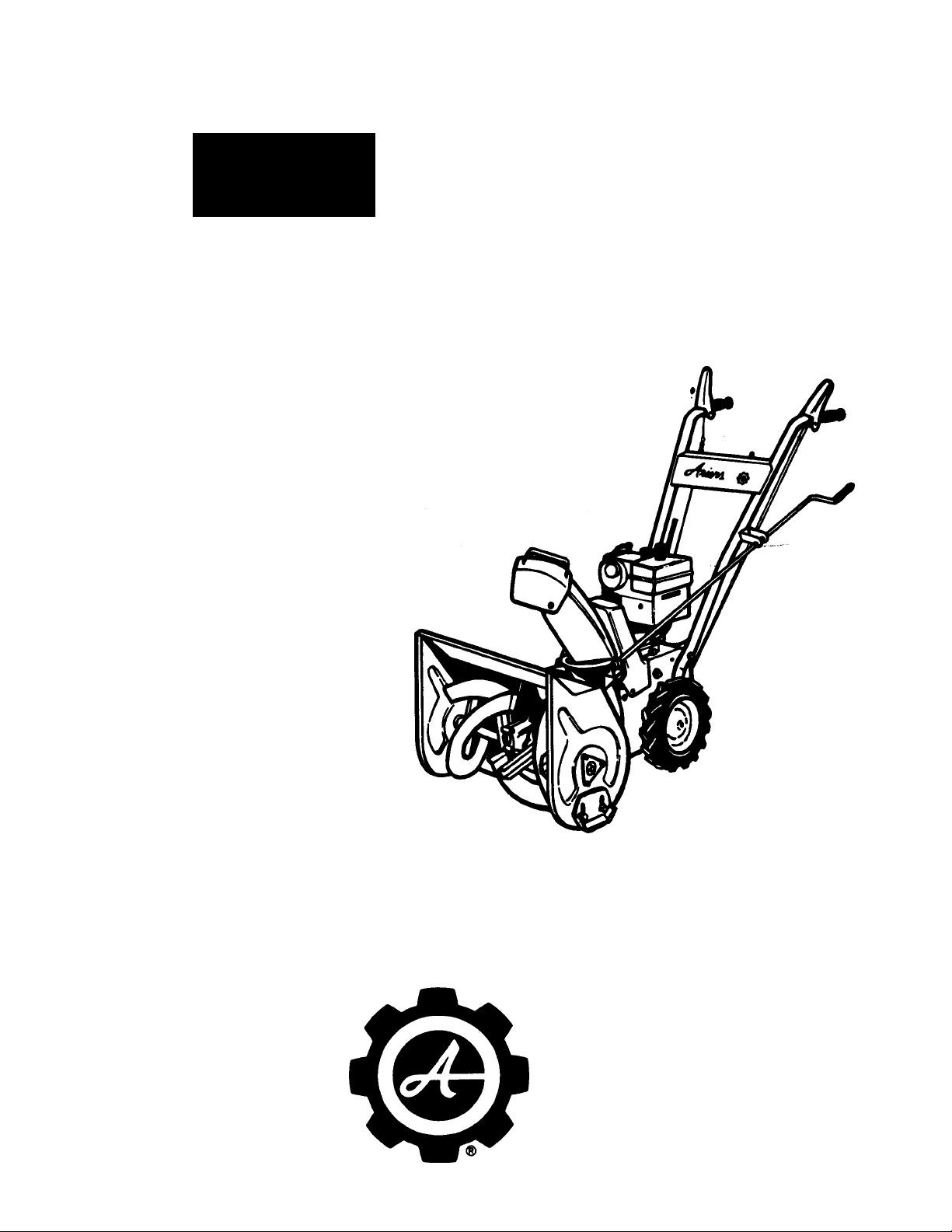
PARTS
MANUAL
SERIAL NUMBER
MODEL NUMBER 932001 - 2.7 H.P.
SERIAL NUMBER 000101 & UP
cA^Umi
2.7 HP.
COMPACT SNO-THRO
PM-32-77
PRICE $.50
ARIENS COMPANY
BRILLION, WIS. 54110
Page 2
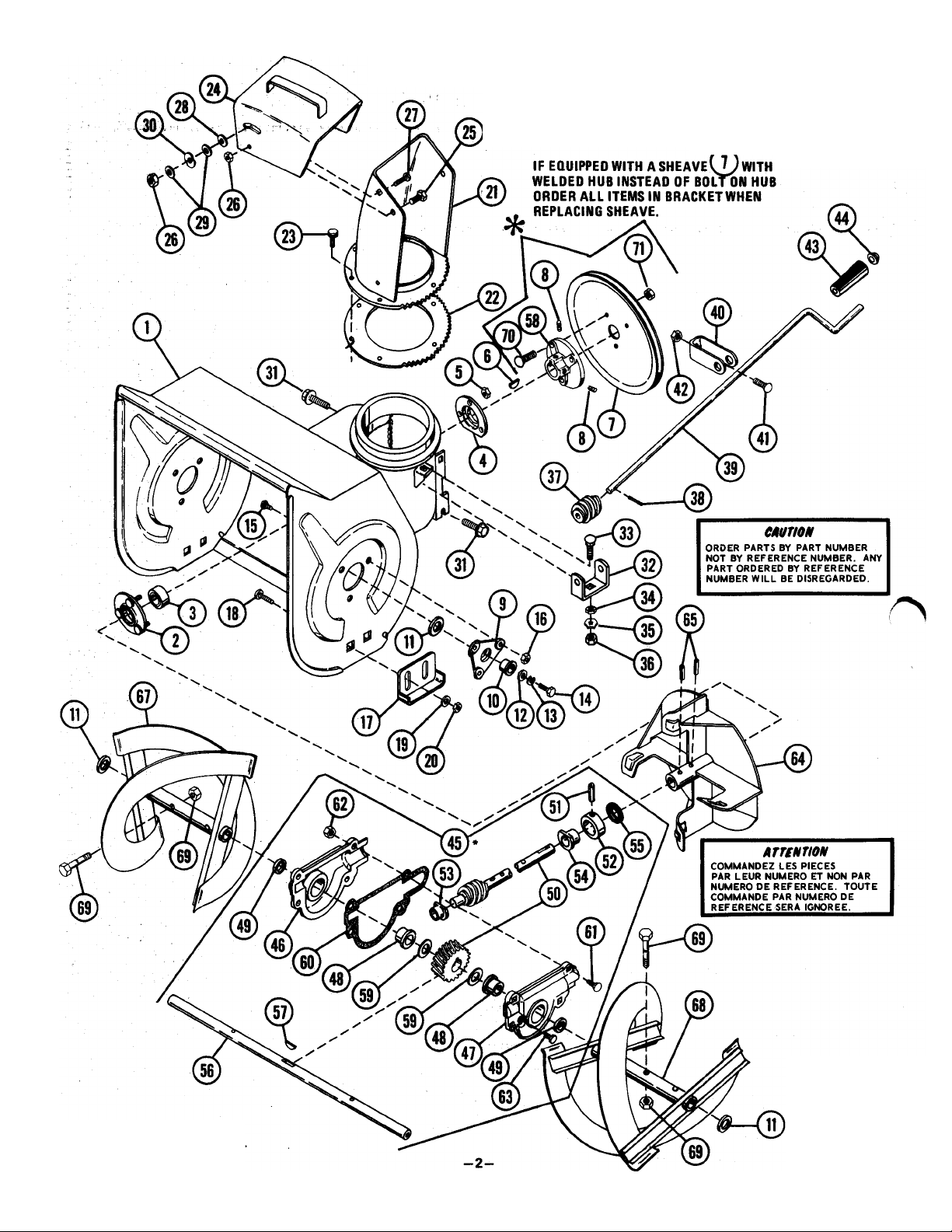
SNO-THRO PARTS LIST FOR MODELS 932001
SOUFFLEURS SNO-THRO _
MOpELES 9320(fj
* Use Ariens Liquid Grease
Part No. 000070. Approx. 2 oz
Page 3

SNO-THRO PARTS LIST FOR MODELS 932001
SOUFFLEURS SNO-THRO MODELES 932001
n
Klo DE No DE code
REF. PIÈCE D'INV.
DESCRIPTION
REF. PART STOCK
NO. NO. CODE
532003
1
010142 M BEARING FLANGE
2
3 054063
003017
4
065040
5
066001
6
073080
7
060005
8
032044
9
055113 F
10
11 064009 M
12 064128 M
063003
13
14 059002 M CAP SCREW, 5/16-18 X 5/8, GR 2
15 070011
16 065056
010165
17
062010
18
064002
19
065039
20
21 022159
022160
22
074034
23
24 522006
25
059039
065042
26
27 062034
28 064168
29 064123
013202
30
31 070009
32 022123
33 062011
34
063032
35
063023
BLOWER HOUSING, W/Decals 1
S
F
GEARING, Radial
BEARING FLANGE
M
LOCKNUT
M
KEY, Woodruff, SAE 11
M
SHEAVE
M
SET SCREW
M
SUPPORT, Bearing
M
FLANGED BUSHING 2
WASHER, 3/4 STD. 4
WASHER
M LOCKWASHER 5/16 STD.
RIBBED NECK BOLT 1/4-20x5/8
M
FLANGED WHIZ LOCKNUT 1/4-20 6
M
RUNNER 2
F
CARRIAGE BOLT, 3/8-16x3/4
M
WASHER, 5/16 STD. 4
M
M LOCKNUT, 3/8-16
CHUTE, Discharge 1
S
GEAR, Lower Collar 1
S
TAPTITE
M
DEFLECTOR CHUTE W/Decal 1
s
M CAP SCREW, 5/16-18 X 1/2, GR 2 2
M LOCKNUT, 5/16-18 3
CARRIAGE BOLT, 5/16-18x3/4 1
M
M WASHER, Plastic 5/16
WASHER, 5/16 STD 2
M
WAVE WASHER 1
M
FLANGE WHIZLOCK SCREW 5/16-18x1/2
M
WORM CLEVIS 1
s
CARRIAGE BOLT, 5/16-18x3/4 1
M
LOCKWASHER 1
M
LOCKWASHER 1
M
QUANTITÉ
NO REQ'D
No DE No DE CODE
REF. PIÈCE DTNV.
REF. PART STOCK
NO. NO. CODE
36 065015
1
1
1
3
1
1
2
2
2
2
2
6
4
4
6
1
4
37
38
39
40
41
42
43 075039
44
45
46 032032
47
48 055102
49
50 532001
51
52 032035
53 055111
54
55 056058
56 032036
57
58
59 064161
60 032038
61
62 065056
63 070010
64
65 058007
66 064009
67 032041
68 032042 s RAKE, Left
69
70 070053
71 065078
022110 M
058034 M
022081 S
532004
062001
065040
010198
532002
032033
056043
058003
055112
066014
002862
062012
032040
532005
DESCRIPTION
M
NUT, Hex, 5/16-18
WORM GEAR
ROLL PIN, 1/8 X 3/4
CHUTE CONTROL CRANK
M
BRACKET, W/Decal
M
CARRIAGE BOLT, 1/4-20x1-1/4
M.
LOCKNUT, 1/4-20
M
GRIP
M
CAP
M
GEAR CASE ASSEMBLY
s
GEAR CASE, Right Half
s
GEAR CASE, Left Half
F
FLANGED BUSHING
F
SEAL
M
FAN SHAFTS: WORM GEAR
M
ROLL PIN, 3/16 X 1-1/4
s
THRUST COLLAR
F
FLANGED BUSHING
F
FLANGED BUSHING
F
"0" RING
S
RAKE SHAFT
M
KEY, Woodruff, SAE 61
M
HUB
M
WASHER
F
GASKET
M
CARRIAGE BOLT, 1/4-20x3/4
M
FLANGED WHIZLOCK NUT
FLANGE WHIZLOCK SCREW 3/8-16x1/2
M
M
FAN
M
ROLL PIN, 1/4 X 1-1/4
M
WASHER, 3/4 STD.
s RAKE, Right
SHEAR BOLTW/Nut
F
M
RIBBED NECK BOLT
M
FLANGE WHIZLOCK NUT
QUANTITÉ
NO REQ’D
1
1
1
1
1
1
1
1
1
1
1
1
2
2
1
1
1
1
1
1
1
1
1
2
1
4
4
1
1
2
2
1
1
2
3
3
^ If equipped with a sheave^ 7ywith welded hub instead of bolt on hub,
order all items in bracket wHen replacing sheave.
SUGGESTED PARTS STOCKING CODE
F - FAST S -SLOW
M - MEDIUM 0 - CUSTOMER ORDER ONLY
NOTE: DECALS SEE PAGE 8.
CODE SUGGÉRÉ D'INVENTAIRE DES PIÈCES
F - FAST (rapide) S -SLOW (lent)
M - MEDIUM (moyen) O - Commande du client seulement
NOTE: DÉCALQUES (voir p. 8.)
-3-
Page 4

TRACTOR PARTS FOR MODEL 932001
PIECES DU TRACTEUR DES MODELE 932001
$0*
S',
S'
r,>P\ 1
I TO ENGINE
MAGNETO
@ @
hd
m @
S®
I
ORDER PARTS BY PART NUMBER
NOT BY REFERENCE NUMBER. ANY |
PART ORDERED BY REFERENCE
NUMBER WILL BE DISREGARDED.
—4--
mmH
>r-®
COMMANDEZ LES PIECES
ikTUHim
PAR LEUR NUMERO ET NON PAR
NUMERO DE REFERENCE. TOUTE
COMMANDE PAR NUMERO DE
REFERENCE SERA IGNOREE.
Page 5

TRACTOR PARTS FOR MODEL 932001
PIECES DU TRACTEUR DES MODELE 932001
No DE No DE
REF. PIÈCE
REF. PART
N0. N0.
1
2 032002
3
4
5
6 064123
7
8 032004
9
10 032005
11 031053
12
13 067004 M PIN, Cotter, 1/8x1
14
15 083141 M SPRING, Extension
16 032006 s IDLER ARM
17 010358
18
19
20 065042
21 055109
22 032007
23 066003
24
25
26
27
28 068062 s RIVET
29
30 032009 S LEVER
31 032010
32
33 032011
34 032012
35 057043
36
37
38
39 065040
40 032013
41 058009
42
43 067001
44 032014
45 055110
46
47 065094
48
49 032016
50 058065
51 071121
1
1 53
1 54 075085
1 55
CODE
D'INV.
STOCK
CODE
032001
065039
032003
083090
059045
070012
064003 M
012086 F
059002 M
064002
073074
060014
632001 s
022178
055037
058026
032029
022013
059028 M CAP SCREW, 1/4-20x1/2
022011 s PINION
062049
032015
071122
058064
032017
DESCRIPTON
0 TRACTOR FRAME
S SHIFTING FORK
M LOCKNUT 3/8-16
SHIFT HANDLE
s
SPRING
M
WASHER, 5/16 STD
M
M CAP SCREW, 5/16-18 X 1-1/2 GR 2
QUADRANT
s
M
FLANGE WHIZLOCK SCREW 1/4-20 x 3/8
CLUTCH FORK
s
SPACER
s
WASHER, 1/2 STD
CAP
M
SPACER BUSHING
CAP SCREW, 5/16-18 X 5/8 GR 2
M
WASHER, 5/16, STD
M
LOCKNUT, 5/16-18
F
FLANGED BUSHING
M
HEX SHAFT
M
KEY, Woodruff, SAE 9
M
SHEAVE
M
SETSCREW 1/4-20x1/4
BRAKE CLUTCH ARM W/Lining
s
BRAKE LINING
F FLANGED BUSHING
S LEVER CLUTCH
M
ROLL PIN, 5/32x7/8
M FRICTION PLATE
M
BEARING FLANGE
F SNAP RING
FRICTION WHEEL HUB
S
F FRICTION DISC
M
LOCKNUT, 1/4-20
M
HEX SHAFT
M ROLL PIN, 1/8x1
M
PIN, Cotter, 3/32 x 3/4
M
BUSHING FLANGE
F
FLANGED BUSHING
M
CARRIAGE BOLT 10-24x3/8
M
TWIN WHIZLOCK NUT 10-24
S
AXLE SHAFT
s
GEAR
M
GROOVE PIN, 3/16x1-1/4
s
WHEEL ASSEMBLY, Right
s
WHEEL ASSEMBLY, Left
M
ROLL PIN, 7/32x1-1/4
M
HOLE PLUG
s
BRACKET
QUANTITÉ
NO. REQ'D.
No DE No DE CODE
REF. PIÈCE D'INV.
REF. PART STOCK
NO. NO. CODE
1
1
1
1
1
1
1
1
8
1
1
4
1
1
1
1
1
1
9
8
4
1
1
1
6
1
1
2
2
1
1
1
1
2
2
1
1
4
7
1
2
1
1
2
2
8
8
1
1
56 059062
57
58 022135
59 060012
60
61
62 058035
63 032028
64
65 002813
66 012132
67
68 062022
69
70 065015
71
72
73
74
75 072106 F
76 032019
77
78
79
80
81 083171
82 032021
83
84
85 532006
86 059069
87
88
89
90 532008
91 532007
92
93
94
95
96 063019 M
97
98
99
100
101 069099
102 070053
103
1
1
1
2
2
1
QUANTITÉ
DESCRIPTION
M
CAP SCREW, 1/4-20x1-3/4, GR 2
059022
032027
067020
083091
012131
063003
062048 M
083172
032018 s SHEAVE, Camshaft 1
066015 M KEY, Woodruff, SAE 5
066013 M
072107
032020 M
059053
032050
032022
M
CAP SCREW, 5/16-18 X 3/4 GR 2
s
ROD ADAPTER
M
SETSCREW 5/16-18 X 3/8 1
M
ROD, Traction Clutch 1
M
HAIR PIN, 3/32x1-3/16
M
ROLL PIN, 1/8 X 1/2
s
STRAP
M
BRAKE SPRING
M
CLEVIS PIN
M
IDLER
M
BEARING SPACER 2
M
CARRIAGE BOLT, 5/16-18 x 1-3/8
M
LOCKWASHER 5/16 STD 6
M
NUT 5/16-18
CARRIAGE BOLT 5/16-18x1-1/4
M
SPRING, Extension
VEE BELT
SHEAVE, Engine
s
KEY, Straight, 3/16x3/16x1
F
VEE BELT 1
BELT FINGER 1
M
CAP SCREW, 5/16-18 X 1/2 GR 2 1
M
SPRING, Extension
COVER, Bottom
s
HUB
s
M BELT COVER
NO. REQ'D.
s HANDLEBAR W/Decal
M
022129
074039 M
075081 M GRIP
032026 M
002042
083008
011134
065075
022161
063018
075086 M
065078
CAP SCREW, 5/16-18 X 1-1/4, GR 2
s
HANDLE PIVOT
SCREW, Self Tapping
s
HANDLE W/Decat
s
HANDLE W/Decal
RDD, Clutch
M
CHAIN 8i CONNECTOR
M
CLUTCH SPRING 1
M
KEY SWITCH
LOCKWASHER
M
NUT, Special
s WIRE, Shorting
M
LOCKWASHER
GRIP, Speed Control
M CLAMP, 2 Wire
RIBBED NECK BOLT, 5/16-18 x 3/4
M
LOCKNUT, 5/16-18
M
ENGINE, Tecumseh HSK35-45503M
NOTE: DECALS SEE PAGE 8.
NOTE; DÉCALQUES (voir p. 8.)
3
3
1
1
1
1
1
1
2
1
1
1
1
1
1
1
1
1
1
1
1
1
2
2
4
2
1
1
1
1
1
1
1
1
1
1
3
3
1
SUGGESTED PARTS STOCKING CODE
F - FAST S - SLOW
M -MEDIUM O -CUSTOMER ORDER ONLY
CODE SUGGÉRÉ D'INVENTAIRE DES PIÈCES
F - FAST (rapide) S -SLOW (lent)
M — MEDIUM (moyen) O - Commande du client seulement
-5-
Page 6

MAINTENANCE
BELT REPLACEMENT
CAUTION:
SINCE REPLACING THE BELTS WILL INVOLVE TURNING
THE ENGINE OVER WITH THE STARTER, THE SPARK
PLUG WIRE MUST BE DISCONNECTED DURING THIS
PROCEDURE.
The drive belt and the attachment drive belt are both ac
cessible by tipping apart the blower housing and tractor as
follows;
REPLACEMENT OF TRACTION DRIVE BELT
With the blower and tractor tipped apart, spring the idler
from the drive belt and remove from around the lower sheave
and engine sheave. Install the new belt on the engine sheave
and lower sheave. Then spring the idle back into position on
the outside of the drive belt.
With the belts in position and the idler in place, check the
belt alignment. The engine sheave and the tractor sheave
must align with one another. If the sheaves are not properly
aligned, loosen the setscrews on the engine sheave and align
the sheaves. Retighten the setscrews.
BLOWER CLUTCH ADJUSTMENT
o
1. Remove the nut and washer holding the worm clevis on
the bracket. Remove the chute crank by sliding it back in
the bracket and out of the way.
2. Remove the two flanged whiziock screws securing the belt
guard to the tractor. Remove the belt guard.
Remove the top cap screws and loosen the lower cap screws
3.
on each side that secures the blower housing to the frame.
As the blower housing and tractor are tipped apart, roll
the belt off the engine sheave between the sheave and belt
finger. This can be easily done by pulling the recoil
starter rope to rotate the engine sheave. With the belt dis
connected, the blower housing may then be tipped from
the frame.
TRACTION IDLER
The blower clutch is adjusted by connecting the spring on
the clutch rod into the proper link on the clutch handle chain.
Properly adjusted, the spring should be slightly extended with
the clutch handle down. This should occur without the
attachment activator lever touching the hub. If the activator
lever touches the hub, the blower belt idler pulley must be ad
justed in the idler arm. Loosen the cap screw on the idler
and move the idler IN TOWARD the belt. Readjust the spring
in the chain for proper action.
BLOWER CLUTCH ROD
HUB
TRACTION CLUTCH ROD .
ACTIVATOR LEVER ^ ^
M\
ROD ADAPTOR
ALLEN SCREW
DRIVE DISC ADJUSTMENT
The only adjustment for the drive disc is made by adjusting
the length of the traction clutch rod. With the clutch handle
in the full upright position and the clutch bracket down
against the stop, tighten the alien screw in the rod adapter.
To check the adjustment, push the Sno-Thro with the clutch
handle up; it should roll freely. While pushing the Sno-Thro,
slowly lower the clutch handle. The wheels should start to
drag with the clutch handle approximately halfway down to
the handlebar grip when properly set. If necessary, adjust
the clutch rod in the rod adapter to secure this adjustment.
NOTE; The hex nut on the clutch link just above the spring
on the clutch linkage is NOT an adjustment. This nut should
be tightened just enough to hold the spring snug and prevent
the spring from rattling when traction clutch is released.
FIGURE 4
REPLACEMENT OF THE BLOWER DRIVE BELT
The blower drive belt remains on the sheave on the blower
housing. Place the new belt on the sheave. Hold it in position
On the sheave as the blower is tipped into position on the
tractor. Be sure the brake shoe seats on the belt as the units
are tipped together. Once assembled, roll the blower belt on to
the engine sheave and position the idler on the outside of
the belt.
REPLACEMENT OF FRICTION WHEEL
1. Tip the machine up on the blower housing and brace
securely. Remove two cap screws at back of frame securing
the bottom cover and loosen two cap screws at front
frame sides and remove the cover.
2. Remove the four whiziock nuts holding the bearing flange
on the right hand side of the frame. Remove the bearing
flange and carriage bolts.
-6-
Page 7

3. Remove the hairpin cotter from the traction clutch rod.
Pull this rod from the clutch fork arm and tip it up and out
of the way.
4. Slide the friction wheel assembly and hex shaft to the right
until the left end of the hex shaft comes free of the left
bearing. Then slip the whole assembly back to the right and
pull it forward out of the frame.
5. With the friction wheel assembly out of the frame, the
three cap screws holding the friction wheel to the hub
may be removed and the friction wheel removed.
6. Position a new friction wheel on the hub and secure with
the three cap screws. Tighten securely.
7. Slip the right end of the complete friction wheel assembly
and hex shaft into the hole in the right side of the frame.
Position the friction wheel hub in the forks. Slide the hex
shaft to the left and into the left bearing being sure flat
washer is in position. See that the pinion gear meshes with
the iarge gear.
8.
Replace the bearing flange on the right side of the frame
and secure with the four carriage bolts and nuts. Reconnect
the traction clutch rod in the clutch fork arm and secure
with a hairpin cotter. Readjust the drive disc as described
in the paragraph on page 6.
NOT AN ADJUSTMENT ^
FORK
TRACTOR DRIVE
At start of season, grease gears, hex and axle shaft as in
dicated in the figure below. Use Ariens Moly Lithium grease.
Put two or three drops of light oil on shift lever and other
linkage points. CAUTION: Do not allow grease or oil to
come in contact with friction wheel, drive disc or belts.
FLAT WASHER
{OUTSIDE OF
PINION)
TRACTION CLUTCH ROD
BEARING FLANGE
FRICTION WHEEL
LUBRICATION
ENGINE
Fill the crankcase with Ariens Sno-Thro oil 5W-20 when using
the Sno-Thro.
Use Ariens Gard-N-Yard oil MS classification SAE-30 when
using lawn attachments.
SNO-THRO UNIT
Check the lubrication in the blower gear case by removing
the filler plug on the side of the gear case just above the left
hand auger shaft. Lubricant should be even with the hole
with the machine sitting level.
y
/ A
To Drain Gear Case: Remove fill plug. Tip up on blower
housing and allow oil to drain. Tip unit back on wheels.
Fill gear case with Ariens Liquid Grease (Part No. 000070).
SHEAR BOLT I
SHAFT
Oil rake shaft periodically or each time a shear bolt is re
placed. At the end of the season, remove shear bolts, oil
rake shaft through shear bolt holes, turn rakes on shaft
several times and replace shear bolts.
Oil the discharge chute with several drops of heavy oil.
FILLER PLUG
Refer to engine owners manual for appropriate crankcase oil
substitutes.
Fill the fuel tank with fresh, clean, unleaded automotive type
gasoline. (Leaded "regular" grade gasoline is an acceptable
substitute.)
NOTE: For detailed instructions on engine refer to manu
facturer's booklet packed with the machine.
-7-
Page 8

ARIENS COMPANY BRILLION. WISCONSIN U S A
A WARNING
STOP ENGINE ANO REMOVE SPARK
ROTATING PARTS
PLUG IGNITION WIRE BEFORE
REMOVING OBSTRUCTIONS
78323
A WARNING
ROTATING PARTS
KEEP CLEAR OF COLLECTOR
RAKES WHILE ENGINE
IS RUNNING
78327
A SAFETY
INSTRUCTIONS
AVOID POTENTIAL HAZARDS
I. вело eWNCRS МШП F9R OPftIfIM ДМ
SirnV INSIRyCTIONS.
t. OtSElIVI «Ц UBIIS MO NSIRUenONS.
1. RDNOI om«T INTIRLOCN tVSUM. II II
FOR YOUR PROtfCTION.
«. HOP IRCINt MO WMI FOR RU MOVEMCRt
TO HOP HFORI UNCIOCCINC OR
SERVICINC MACHINE.
S. NEVER mow CIIHOREN 10 OPfRAIE INI
EOUIPMENI. NEVER ALLOW AOULIS 10
OPERATE 1HE EOUIPMENI WITHOUT PNOPEI
INSTRUCTION.
I. KEEP THE AREA OF OPERATION CLUR OF
Ш PERSONS. tSPECIRUV CHILDREN.
I NEVER RIRSCT DISCHARGE AT 0TS1AH0ENI
OR ALLOW АНТОНЕ IN FNONT OF UNIT.
S. RfFP MACHINE PROPEtlV MAINTAINIO ANO
SEOVICEO WITH RLl SNIEIOI. CUAIOS, ANO
PROTECTIVE OCVICES IN PUCE.
78416
78061
SPEED SELECTOR
13 — 2-1
---------
78456
CLUTCH
LEVER
DEPRESS
ni
mACNMENT
Nin
78455
FOR
WHEEL
DRIVE
78324
DISCHARGE
RIGHT LEFT
78325
FAST -
STOP^
CHOKE-THROTTLE DECALS
available from TECUMSEH
OFF 1/2 3/4 FULL
CHOKE
ATTENTION
WHEN USING SUMMER ATTACHMENTS
REMOVE HEATER BOX AND INSTALL
AIR CLEANER
78189
KEY
SWITCH
F
OPCRATINO INSTNUCTIONS
мер» TO OWNCRS MANUAL
TO AT ANT TURN KIT SWITCH OH AND PULL STAATEN
TO STOP TURN KEY SWITCH TO OPS ANO REMOVE KEY
78457
TMHMTILt
ELECTRIC STMTHI
PUSH ID 5ТЛЙТ
78357
(120V AC STARTER
KIT ONLY)
78345
78174
ENGINE PRilVIER
PUSH TO PRIME
78395
COMPLIANCE WITH CANADIAN RADIO INTERFERENCE REGULATIONS CERTIFIED
_______REPLACE SPARK PLUG WITH RESISTOR SPARK PLUG ONLY '
CERTFIE CONFORME AU REGLEMENT CANADIEN SUR LE BROUILLAGE RAOIOELECTRIOUE
REMPLACER LA ROUPIE PAR UNE ROUGIE A RESISTANCE SEULEMENT '
78400
A HIGH SPEED IMPELLER ROTATES
INSIDE THIS HOUSING TO THROW
THE SNOW. NEVER REACH OR PUSH
ANY OBJECT INTO THE DISCHARGE
CHUTE WITH THE IMPELLER
ROTATING!
 Loading...