

Sno-Thro
E10
Service Guide
Deluxe Series
Models
921045 – Deluxe 24
(SN 000101 +)
®
921046 – Deluxe 28
(SN 000101 +)
921047 – Deluxe 30
(SN 000101 +)
921048 – Deluxe 28 SHO
(SN 000101 +)
921049 – Deluxe 30 EFI
(SN 000101 +)
921323 – Deluxe 24 CE
(SN 000101 +)
921324 – Deluxe 28 CE
(SN 000101 +)
921325 – Deluxe 30 CE
(SN 000101 +)
921326 – Deluxe 28 Track CE
(SN 000101 +)
ENGLISH
05001330D • 1/17

TABLE OF CONTENTS
PRACTICES & LAWS . . . . . . . . . . . . . . . . . . . . . . . . . . 2
EMISSION CONTROL SYSTEM . . . . . . . . . . . . . . . . . . 2
REQUIRED OPERATOR TRAINING. . . . . . . . . . . . . . . 2
SAFETY ALERT SYMBOL . . . . . . . . . . . . . . . . . . . . . . 2
SIGNAL WORDS . . . . . . . . . . . . . . . . . . . . . . . . . . . . . . 2
SAFETY DECALS . . . . . . . . . . . . . . . . . . . . . . . . . . . . . 3
Safety Decal Locations . . . . . . . . . . . . . . . . . . . . . . . . . . . . . . 3
Safety Decal Descriptions. . . . . . . . . . . . . . . . . . . . . . . . . . . . 3
SAFETY RULES . . . . . . . . . . . . . . . . . . . . . . . . . . . . . . 4
DRAINING FUEL SYSTEM . . . . . . . . . . . . . . . . . . . . . . 7
SERVICE POSITION . . . . . . . . . . . . . . . . . . . . . . . . . . . 7
SEPARATE HOUSING FROM FRAME. . . . . . . . . . . . . 7
Remove Auger Housing . . . . . . . . . . . . . . . . . . . . . . . . . . . . . 7
Reinstall Auger Housing . . . . . . . . . . . . . . . . . . . . . . . . . . . . . 10
BOTTOM COVER REMOVAL . . . . . . . . . . . . . . . . . . . . 12
Install Bottom Cover . . . . . . . . . . . . . . . . . . . . . . . . . . . . . . . . 13
ATTACHMENT DRIVE BELT REPLACEMENT . . . . . . 13
Remove Attachment Drive Belts. . . . . . . . . . . . . . . . . . . . . . . 13
Install Attachment Drive Belts. . . . . . . . . . . . . . . . . . . . . . . . . 13
TRACTION DRIVE BELT REPLACEMENT . . . . . . . . . 14
Remove Traction Drive Belt . . . . . . . . . . . . . . . . . . . . . . . . . . 14
Install Traction Drive Belt . . . . . . . . . . . . . . . . . . . . . . . . . . . . 15
ATTACHMENT BRAKE REPLACEMENT . . . . . . . . . . 16
Remove Attachment Brake. . . . . . . . . . . . . . . . . . . . . . . . . . . 16
Install Attachment Brake. . . . . . . . . . . . . . . . . . . . . . . . . . . . . 16
FRICTION DISC REPLACEMENT. . . . . . . . . . . . . . . . . 17
Remove Friction Disc . . . . . . . . . . . . . . . . . . . . . . . . . . . . . . . 17
Install Friction Disc . . . . . . . . . . . . . . . . . . . . . . . . . . . . . . . . . 19
HEX SHAFT BEARING REPLACEMENT . . . . . . . . . . . 20
Remove Bearing. . . . . . . . . . . . . . . . . . . . . . . . . . . . . . . . . . . 20
Install Bearing. . . . . . . . . . . . . . . . . . . . . . . . . . . . . . . . . . . . . 20
SWING GATE REPLACEMENT . . . . . . . . . . . . . . . . . . 20
Remove Swing Gate Assembly. . . . . . . . . . . . . . . . . . . . . . . . 20
Install Swing Gate Assembly. . . . . . . . . . . . . . . . . . . . . . . . . . 21
AUGER REPLACEMENT . . . . . . . . . . . . . . . . . . . . . . . 22
Remove Auger . . . . . . . . . . . . . . . . . . . . . . . . . . . . . . . . . . . . 22
Install Auger . . . . . . . . . . . . . . . . . . . . . . . . . . . . . . . . . . . . . . 24
AUGER GEARCASE REPLACEMENT. . . . . . . . . . . . . 26
Remove Gearcase Assembly . . . . . . . . . . . . . . . . . . . . . . . . . 26
Install Gearcase Assembly . . . . . . . . . . . . . . . . . . . . . . . . . . . 26
IMPELLER REPLACEMENT. . . . . . . . . . . . . . . . . . . . . 27
Remove Impeller. . . . . . . . . . . . . . . . . . . . . . . . . . . . . . . . . . . 27
Install Impeller. . . . . . . . . . . . . . . . . . . . . . . . . . . . . . . . . . . . . 27
TRACTION DRIVE CABLE REPLACEMENT. . . . . . . . 31
Remove Traction Drive Clutch Cable . . . . . . . . . . . . . . . . . . . 31
Install Traction Drive Clutch Cable . . . . . . . . . . . . . . . . . . . . . 32
DUAL-HANDLE INTERLOCK CAM REPLACEMENT . 33
Remove Interlock Cam . . . . . . . . . . . . . . . . . . . . . . . . . . . . . . 33
Install Interlock Cams . . . . . . . . . . . . . . . . . . . . . . . . . . . . . . . 34
AXLE BUSHING REPLACEMENT . . . . . . . . . . . . . . . . 35
Remove Left Axle Bushing . . . . . . . . . . . . . . . . . . . . . . . . . . . 35
Install Left Axle Bushing . . . . . . . . . . . . . . . . . . . . . . . . . . . . . 35
Remove Right Axle Bushing . . . . . . . . . . . . . . . . . . . . . . . . . . 36
Install Right Axle Bushing . . . . . . . . . . . . . . . . . . . . . . . . . . . . 37
FLANGE BUSHING REPLACEMENT . . . . . . . . . . . . . 38
Install Flange Bushings. . . . . . . . . . . . . . . . . . . . . . . . . . . . . . 39
DIFFERENTIAL GEAR REPLACEMENT . . . . . . . . . . . 39
Remove Differential Gear . . . . . . . . . . . . . . . . . . . . . . . . . . . . 39
Install Differential Gear . . . . . . . . . . . . . . . . . . . . . . . . . . . . . . 40
CHUTE GEAR REPLACEMENT. . . . . . . . . . . . . . . . . . 41
Remove Chute Rotation Gear. . . . . . . . . . . . . . . . . . . . . . . . . 41
Remove Chute Rotation Gear. . . . . . . . . . . . . . . . . . . . . . . . . 42
Install Chute Rotation Gear. . . . . . . . . . . . . . . . . . . . . . . . . . . 42
Install Chute Rotation Gear. . . . . . . . . . . . . . . . . . . . . . . . . . . 43
Remove Actuation Gear . . . . . . . . . . . . . . . . . . . . . . . . . . . . . 44
Remove Actuation Gear . . . . . . . . . . . . . . . . . . . . . . . . . . . . . 44
Install Actuation Gear . . . . . . . . . . . . . . . . . . . . . . . . . . . . . . . 45
Install Actuation Gear . . . . . . . . . . . . . . . . . . . . . . . . . . . . . . . 45
SCRAPER BLADE REPLACEMENT . . . . . . . . . . . . . . 45
Remove Scraper Blade. . . . . . . . . . . . . . . . . . . . . . . . . . . . . . 45
Install Scraper Blade. . . . . . . . . . . . . . . . . . . . . . . . . . . . . . . . 46
HEADLIGHT REPLACEMENT . . . . . . . . . . . . . . . . . . . 46
Remove Bulb. . . . . . . . . . . . . . . . . . . . . . . . . . . . . . . . . . . . . . 46
Install Bulb. . . . . . . . . . . . . . . . . . . . . . . . . . . . . . . . . . . . . . . . 47
GEARCASE REBUILD . . . . . . . . . . . . . . . . . . . . . . . . . 47
Disassemble Gearcase. . . . . . . . . . . . . . . . . . . . . . . . . . . . . . 47
Assemble Gearcase . . . . . . . . . . . . . . . . . . . . . . . . . . . . . . . . 49
TRACK DRIVE WHEEL REPLACEMENT . . . . . . . . . . 53
Remove Track Drive Wheel . . . . . . . . . . . . . . . . . . . . . . . . . . 53
Install Track Drive Wheel . . . . . . . . . . . . . . . . . . . . . . . . . . . . 54
TRACK REPLACEMENT . . . . . . . . . . . . . . . . . . . . . . . 54
Remove Track. . . . . . . . . . . . . . . . . . . . . . . . . . . . . . . . . . . . . 54
Install Track. . . . . . . . . . . . . . . . . . . . . . . . . . . . . . . . . . . . . . . 55
BOGIE WHEEL REPLACEMENT . . . . . . . . . . . . . . . . . 55
Remove Bogie Wheel . . . . . . . . . . . . . . . . . . . . . . . . . . . . . . . 55
Install Bogie Wheel . . . . . . . . . . . . . . . . . . . . . . . . . . . . . . . . . 55
TRACK BEARING REPLACEMENT. . . . . . . . . . . . . . . 56
Remove Bearing From Left Side of Unit . . . . . . . . . . . . . . . . . 56
Install Bearing to Left Side of Unit. . . . . . . . . . . . . . . . . . . . . . 57
Remove Bearing From Right Side of Unit. . . . . . . . . . . . . . . . 58
Install Bearing to Right Side of Unit. . . . . . . . . . . . . . . . . . . . . 59
EFI REPLACEMENT COMPONENTS . . . . . . . . . . . . . 60
ENGINE REPLACEMENT . . . . . . . . . . . . . . . . . . . . . . . 28
Remove Engine. . . . . . . . . . . . . . . . . . . . . . . . . . . . . . . . . . . . 28
Install Engine . . . . . . . . . . . . . . . . . . . . . . . . . . . . . . . . . . . . . 29
EFI TROUBLE CODE IDENTIFICATION . . . . . . . . . . . 60
CHECKING TROUBLE CODES . . . . . . . . . . . . . . . . . . 61

TROUBLE CODE DIAGNOSTICS. . . . . . . . . . . . . . . . . 61
Code 16: Low Battery Voltage . . . . . . . . . . . . . . . . . . . . . . . . 61
Code 21: Barometer Sensor. . . . . . . . . . . . . . . . . . . . . . . . . . 62
Code 22: Engine Temperature Sensor. . . . . . . . . . . . . . . . . . 62
Code 27: Low Fuel Pressure. . . . . . . . . . . . . . . . . . . . . . . . . . 63
Code 28: High Battery Voltage . . . . . . . . . . . . . . . . . . . . . . . . 64
DIAGNOSTICS FOR NON-TROUBLE CODES. . . . . . . 64
Engine Starts and Loses Power . . . . . . . . . . . . . . . . . . . . . . . 64
Engine No-Start Condition . . . . . . . . . . . . . . . . . . . . . . . . . . . 64
Surging Run Condition . . . . . . . . . . . . . . . . . . . . . . . . . . . . . . 66
Engine Speed Does Not Change . . . . . . . . . . . . . . . . . . . . . . 66


Have Questions or Need Assistance?
ariensstore.com (Dealer Locator)
ariens.custhel p. com (Sel f-Support)
A parts manual and an operato r’s manual for your unit are
available for free download or purchase at ariens.com.
Ariens recommends using only genuine Ariens replacement parts on this unit. Using unauthorized
parts may adversely affect the performance, durability or safety of this unit and may void the warranty.
Installing unauthorized parts will not automatically void the warranty; however, the warranty will not
apply if the installation and use of unauthorized parts damages the unit. The Ariens warranty applies
solely to defects in Ariens materials and / or factory workmanship. Arien s disclaims liability for any
claims or dama ges – whet her warra nty, proper ty damage, personal injury or death – ari sing from u sing
unauthorized repl ace m en t par ts.
Before operating or servicing the unit, carefully and completely read the Operator’s Manual and
engine manual provided with the unit at time of purchase. They contain important safety instructions
and information about unit controls.
Be aware of your mechanical aptitude when applying information in this manual for service and / or
repairs. If you are not comfortable or capable of completing service and / or repairs to the machine,
take the machine to an authorized Ariens service dealer.
WELCOME
EN – 1
SAFETY
SAFETY ALERT SYMBOL
Read these safety rules and follow them closely. Failure to
follow these rules could lead to loss of control of unit,
severe personal injury or death to you or bystanders, or
result in damage to property or the machine.
PRACTICES & LAWS
Practice usual and customary safe working precautions.
Learn applicable rules and laws in your area. Always follow
the practices set forth in this manual.
EMISSION CONTROL SYSTEM
This equipment and/or its engine may include exhaust and
evaporative emissions control system components
required to meet U.S. Environmental Protection Agency
(EPA) and/or California Air Resources Board (CARB)
regulations. Tampering with emission controls and
components by unauthorized personnel may result in
severe fines or penalties. Emission controls and
components can only be adjusted by an Ariens Company
dealer or an authorized engine manufacturer's service
center. Contact your Ariens Company Equipment Retailer
concerning emission controls and component questions.
This is the safety alert symbol. It means:
• ATTENTION!
• YOUR SAFETY IS INVOLVED!
When you see this symbol:
• BECOME ALERT!
• OBEY THE MESSAGE!
SIGNAL WORDS
The safety alert symbol above and signal words below are
used on decals and in this manual. Read and understand
all safety messages.
1. Danger
DANGER: Indicates an IMMINENTLY
HAZARDOUS SITUATION! If not avoided, WILL
RESULT in death or serious injury.
2. Warning
WARNING: Indicates a POTENTIALLY
HAZARDOUS SITUATION! If not avoided,
COULD RESULT in death or serious injury.
REQUIRED OPERATOR TRAINING
Read and understand the Operator's Manual
and decals on the unit. This information is for
your safety and the proper use of your
equipment. Failure to follow these instructions
and warnings may cause death or serious
injury. If you have purchased this product from an Ariens
dealer, the dealer can provide you with training.
Familiarize yourself and any other operators with all
controls and the safe use of the features of this unit. If you
loan, rent or sell this product to others, provide them with all
manuals.
If you have any questions, please call our customer support
line at 920-756-4688 or contact us at www.ariens.com. Do
not use this equipment if, after reading the Operator's
Manual and the on-board decals, you have any questions
about the safe use of this product.
WARNING: AVOID INJURY. This snow thrower
is capable of crushing or amputating body parts.
Failure to observe the safety instructions in the
manuals and on decals could result in serious
injury or death.
ALWAYS disengage auger, stop unit and engine,
remove key and allow moving parts to stop
before leaving operator’s position.
3. Caution
CAUTION: Indicates a POTENTIALLY
HAZARDOUS SITUATION! If not avoided, MAY
RESULT in minor or moderate injury . It may als o
be used to alert against unsafe practices.
4. Notice
NOTICE: Indicates information or procedures that are
considered important but not hazard related. If not
followed, property damage could result.
5. Important
IMPORTANT: Indicates general reference information
worthy of special attention.
EN – 2
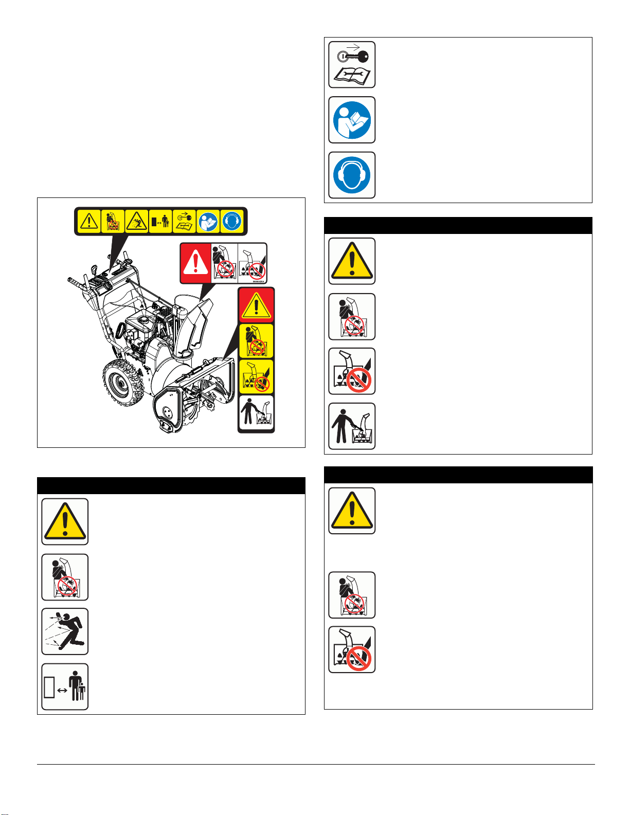
SAFETY DECALS
08000519B
080000945
Figure 1
3
2
1
The safety decals on your machine are visual reminders of
the important safety information in this manual. All
messages on your unit must be fully understood and
carefully followed. Safety decals on the machine are
explained below.
Always replace missing or damaged safety decals.
Replacement decal information is in the parts manual for
your machine. Decals can be ordered from your dealer.
See Figure 1 for safety decal locations.
Safety Decal Locations
Stop engine, remove key, and read manual
before making any repairs or adjustments.
Read Operator’s Manual.
Wear appropriate hearing protection.
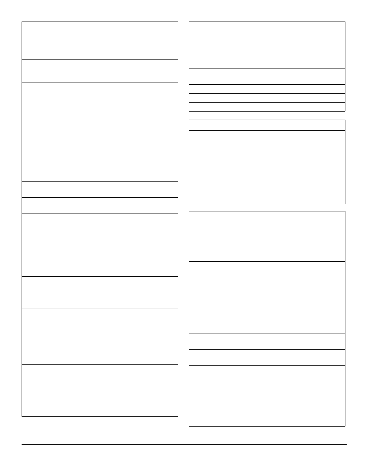
2. DANGER!
Danger!
ROTATING PARTS! Only use clean-out tool
to clear blockages. NEVER use your hands.
Safety Decal Descriptions
1. CAUTION!
Danger!
Only use clean-out tool to clear blockages.
NEVER use your hands.
NEVER direct discharge towards persons or
property that may be injured or damaged by
thrown objects.
Keep people away from unit while operating.
Keep children out of work area and under
watchful care of a responsible adult.
High-speed auger/impeller rotates below
discharge opening. Wait for all moving parts
to stop before removing clogs or servicing.
3. DANGER!
Danger!
ROTATING PARTS! Keep clear of auger
while engine is running.
• Read Operator’s Manual.
• Allow operation only by properly-trained
adult, never children.
• Stop engine and remove ignition key prior
to leaving the operator’s position for any
reason.
• Keep all controls, guards and safety
devices properly se rv ic ed and funct ion al.
• NEVER direct discharge towards persons
or property that may be injured or damaged
by thrown objects.
EN – 3

SAFETY RULES
The following safety instructions are based on the B71.3
specifications of the American National Standards Institute
in effect at the time of production.
Training
Read, understand and follow all instructions on the
machine and in the manual(s) before operating this unit.
Be thoroughly familiar with the controls and the proper use
of the equipment. Know how to stop the unit and
disengage the controls quickly.
Never allow children to operate or play on or near the
equipment. Never allow adults to operate the equipment
without proper instruction.
Keep the area of operation clear of all persons,
particularly small children. Be alert and shut off unit if
children enter area.
Exercise caution to avoid slipping or falling, especially
when operating the snow thrower in reverse.
Always remove key and/or wire from spark plug before
assembly, maintenance or service. Unintentional engine
start up can cause death or serious injury.
Complete a walk-around inspection of the unit to
understand the unit, your work area and all safety decals.
Understand how to operate all controls, the functions of all
controls and how to STOP in an emergency.
Handle fuel with care; it is highly flammable.
• Use an approved fuel container.
• Never add fuel to a running engine or hot engine.
• Fill fuel tank outdoors with extreme care. Never fill fuel
tank indoors.
• Never fill containers inside a vehicle or on a truck or
trailer bed with a plastic liner. Always place containers
on the ground, away from your vehicle, before filling.
• When practical, remove gas-powered equipment from
the truck or trailer and refuel it on the ground. If this is
not possible, then refuel such equipment on a trailer
with a portable container, rather than from a gasoline
dispenser nozzle.
• Keep the nozzle in contact with the rim of the fuel tank
or container opening at all times, until refueling is
complete. Do not use a nozzle lock-open device.
• Replace gasoline cap securely and wipe up spilled fuel.
• If fuel is spilled on clothing, change clothing
immediately.
Adjust the auger / impeller housing height to clear gravel
or crushed rock surface.
Never attempt to make any adjustments while the engine
is running (except when specifically recommended by
manufacturer).
Always allow unit and engine to adjust to outdoor
temperature before clearing snow.
Preparation
Always check overhead and side clearances carefully
before operation.
Always be aware of traffic when operating near streets or
along curbs.
Thoroughly inspect the area where the equipment is to be
used and remove all doormats, sleds, boards, toys, wires
and other foreign objects.
Disengage all clutches and shift into neutral before
starting the engine.
Use extension cords and receptacles as specified by the
manufacturer for all units with electric drive motors or
electric starting motors.
Operation
Disengage all controls before starting engine.
Never leave a running unit unattended. Always stop
engine and remove key before leaving unit to prevent
unauthorized use.
Do not put hands or feet near or under rotating parts.
Keep clear of the discharge opening at all times.
Moving and/or rotating parts can cut off body parts such
as fingers or a hand. NEVER place your hands, other
body part or clothing near any moving parts while unit is
running.
Always keep hands away from all pinch points.
Do not touch parts which might be hot from operation.
Allow parts to cool before attempting to maintain, adjust or
service.
Thrown objects can cause injury. Check for weak spots on
docks, ramps or floors. Avoid uneven work areas and
rough terrain and stay alert for hidden hazards.
Exercise extreme caution when operating on or crossing
gravel drives, walks or roads. Stay alert for hidden
hazards or traffic.
EN – 4
After striking a foreign object, stop the engine, remove the
wire from the spark plug, disconnect the cord on electric
motors, thoroughly inspect the snow thrower for any
damage, and repair the damage before restarting and
operating the snow thrower.
If the unit should start to vibrate abnormally, stop the
engine and check immediately for the cause. Vibration is
generally a warning of trouble.
Stop the engine whenever you leave the operating
position, before unclogging the auger / impeller housing or
discharge chute, and when making any repairs,
adjustments or insp ec tions.
When cleaning, repairing or inspecting the snow thrower,
stop the engine and make certain the auger / impeller and
all moving parts have stopped. Disconnect the spark plug
wire and keep the wire away from the plug to prevent
someone from accidentally starting the engine.
Do not run the engine indoors, except when starting the
engine and for transporting the snow thrower in or out of
the building. Open the outside doors; exhaust fumes are
dangerous.
Never operate the snow thrower without proper guards,
and other safety protective devices in place and working.
Always stand clear of the discharge area when operating
this unit.
Never direct the discharge toward people or areas where
injury or property damage can occur from thrown objects.
Keep children and others away.
Do not overload the machine capacity by attempting to
clear snow at too fast a rate.
Never operate the machine at high transport speeds on
slippery surfaces. Loo k behind and us e care when
operating in reverse.
Do not operate in reverse unless absolutely necessary.
Always back up slowly and look down and behind before
and while backing.
Do not carry passengers.
Disengage attachment when not in use and when
traveling from one work area to another.
Disengage power to the auger / impeller when snow
thrower is transported or not in use.
Use only attachments and accessories approved by the
manufacturer of the snow thrower (such as wheel weights,
counterweights or cabs).
This product is equipped with an internal combustion
engine. Do not use unit on or near any unimproved,
forest-covered or brush-covered land unless exhaust
system is equipped with a spark arrester meeting
applicable local, state or federal laws. A spark arrester, if
used, must be maintained in effective working order by
operator.
Never operate the snow thrower without good visibility or
light. Always be sure of your footing, and keep a firm hold
on the handles. Walk; never run.
Never operate unit after or during the use of medication,
drugs or alcohol. Safe operation requires complete and
unimpaired attention at all times.
Never allow anyone to operate this unit when their
alertness or coordination is impai r ed.
Never touch a hot engine or muffler.
Avoid contact with sharp edges; sharp edges can cut.
Do not throw snow higher than necessary.
Clearing a Clogged Discharge Chute
Hand contact with the rotating auger / impeller inside the
discharge chute is the most common cause of injury
associated with snow throwers. Never use your hand to
clean out the discharge chute.
To clear the chute:
1. SHUT THE ENGINE OFF!
2. Wait 10 seconds to be sure the auger / impeller
blades have stopped rotating.
3. Always use a clean-out tool, not your hands.
Maintenance and Storage
Secure unit so it will not tip over during maintenance.
Before cleaning, removing clogs or making any
inspections, repairs, etc., disengage clutch(es), stop
engine, remove key, allow moving parts to stop and hot
parts to cool.
Check shear bolts and other bolts at frequent intervals for
proper tightness to be sure the equipment is in safe
working condition.
Check clutch and brake operation frequently.
Do not change engine governor settings and do not over-
speed engine.
Adjust and service as required. Motion of drive wheels
and auger / impeller must stop quickly when clutch levers
are released.
Always maintain unit in safe operating condition.
Damaged or worn out muffler can cause fire or explosion.
Keep unit free of ice or other debris. Clean up oil or fuel
spills.
Always keep protective structures, guards, and panels in
good repair and secured in place. Never modify or remove
safety devices.
Never store the machine with fuel in the fuel tank inside a
building where ignition sources are present such as hot
water heaters, space heaters or clothes dryers. Close fuel
valve and allow the engine to cool completely before
storing in any enclosure or covering the unit.
EN – 5
Always refer to operator's manual for important details if
the snow thrower is to be stored for an extended period.
Maintain or replace safety and instruction labels as
necessary.
Run the machine a few minutes after throwing snow to
prevent freeze-up of the auger / impeller.
Personal Protection
Do not operate the equipment without wearing adequate
winter garments. Avoid loose fitt ing clothing that can get
caught in moving parts. Wear footwear that will improve
footing on slippery surfaces.
Wear adequate safety gear, including safety glasses with
side shields and protective gloves.
Do not wear loose clothing or jewelry, and tie back hair
that may get caught in rotating parts.
NEVER attempt to unclog or clean unit while engine is
running. Rotating auger / impeller can cause serious
injury.
Protect eyes, face and head from objects that may be
thrown from unit. Wear appropriate hearing protection.
Always wear safety glasses or eye shields during
operation or while performing an adjustment or repair to
protect ey es f rom f orei gn o bje cts t hat may be thr ow n fr om
the machine.
Slope Operation
Exercise extreme caution when operating on slopes. DO
NOT operate on steep slopes. DO NOT clear snow across
the face of slopes; go up and down. Keep all movement
on slopes slow and gradual.
Use a slow speed to avoid stops or shifts on slopes. Avoid
starting or stopping on a slope. Do not park unit on a slope
unless absolutely necessary. When parking on a slope
always block the wheels.
Do not operate near drop-offs, ditches, or embankments.
Unit can suddenly turn over if a wheel is over the edge of
a cliff or ditch, or if an edge caves in.
Never fill fuel containers inside a vehicle or on a truck or
trailer bed with a plastic liner. Always place containers on
the ground away from your vehicle before filling.
When prac ti ca l, r e mo v e ga s -po w e re d e qu i pm e nt f r o m the
truck or trailer and refuel it on the ground. If this is not
possible, then refuel on a trailer with a portable container,
rather than from a gasoline dispenser nozzle.
Keep the nozzle in contact with the rim of the fuel tank or
container opening at all times until fueling is complete. Do
not use a nozzle lock-open device.
If fuel is spilled on clothing, change clothing immediately.
Properly remove fuel before tipping unit up onto housing
to avoid spills.
Towing/Transporting
Always stop engine, remove key and close fuel valve or
drain fuel when transporting unit on a truck or trailer.
Use extra care when loading or unloading unit onto trailer
or truck. Secure unit chassis to transport vehicle . N ever
secure from rods or linkages that could be damaged. Do
not transport machine while engine is running.
Accessories
Use only Ariens Company-recommended attachments or
accessories that are designed for your unit and that are
appropriate to your use and can be used safely in your
application.
Fuel
DO NOT run engine in an enclosed area. Always provide
good ventilation. Fumes from engine exhaust can cause
injury or death.
Fuel is highly flammable and its vapors are explosive.
Handle with care. Use only an approved gasoline
container with an appropriately-sized dispensing spout.
No smoking, no sparks, no flames. Always allow engine to
cool before servicing.
Never fill fuel tank when engine is running or hot from
operation.
Never fill or drain fuel tank indoors.
Replace fuel cap securely and clean up spilled fuel.
EN – 6
DRAINING FUEL SYSTEM
Figure 2
Figure 3
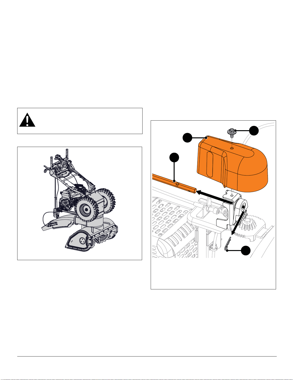
1. Tapping Screw
2. Chute Gear Cover
3. Hex Rod
4. Hairpin
1
2
3
4
SEPARATE HOUSING FROM FRAME
1. Move unit to an open, well-ventilated area with no
flames or sparks.
2. Remove fuel tank cap and siphon fuel into a clean
gasoline container.
3. Reinstall fuel tank cap and tighten.
4. Start engine to burn remaining fuel in fuel system and
leave engine running until it “runs dry” and stops.
Refer to Operator’s Manual for engine start procedure.
5. Stop engine, remove key and close fuel valve.
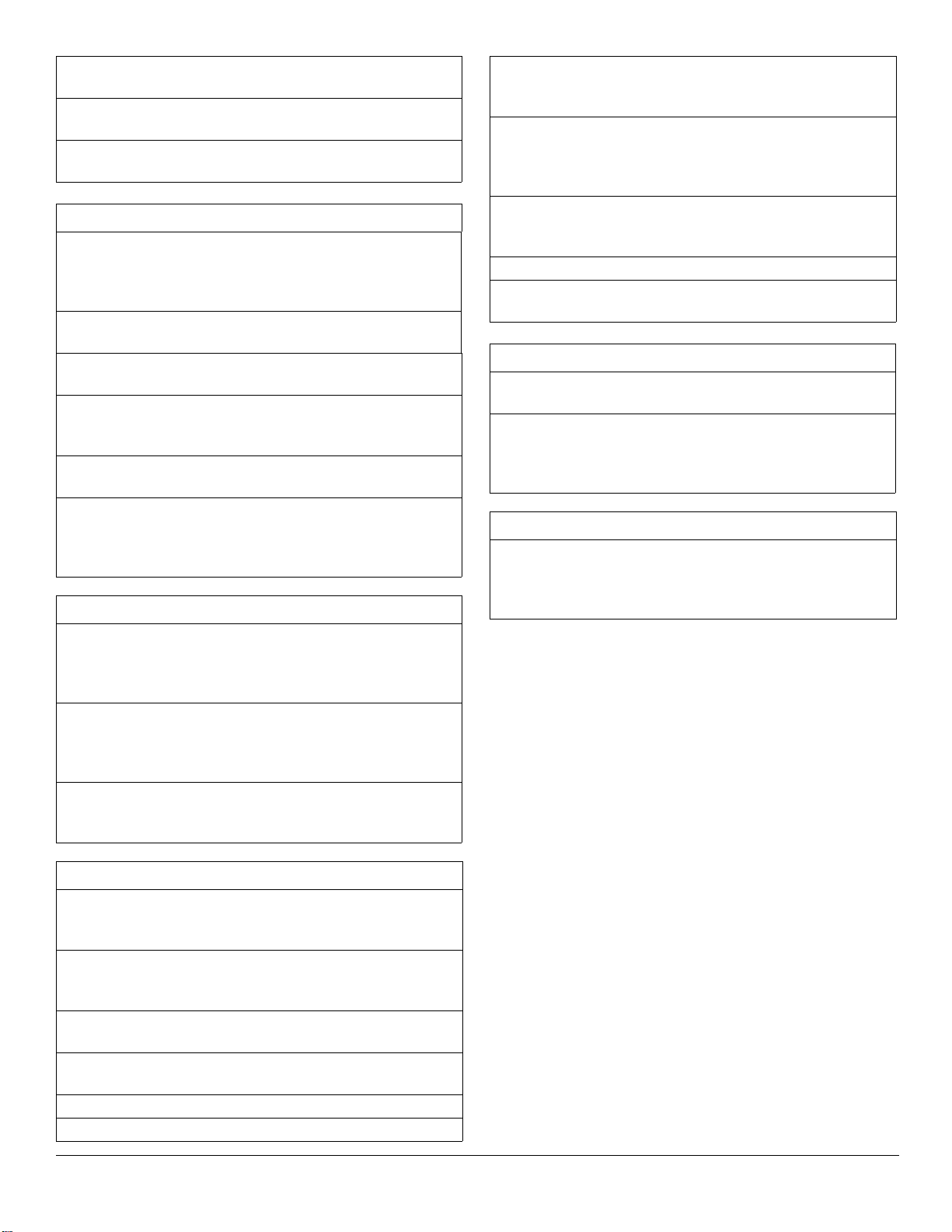
SERVICE POSITION
See Figure2.
WARNING: AVOID INJURY. Before placing unit
in service position, drain fuel from tank and fuel
system. See Draining Fuel System on page 7.
Make sure unit is secure and will not tip.
NOTICE: NEVER store unit in service position.
Remove Auger Housing
IMPORTANT: Save all hardware for reinstallation.
1. Stop engine, remove key and wait for moving parts to
stop and for hot parts to cool.
2. Disconnect spark plug wire from engine.
3. Remove hardware retaining chute gear cover to chute
pedestal and remove cover.
IMPORTANT: For Models 921045, 921046, 921047,
921048, 921049, 921323, 921324, 921325, advance to
step 7.
Model 921326
See Figure 3.
1. Remove hairpin from hex rod and remove hex rod
from chute gears.
EN – 7

See Figure4.
Figure 4
1. Hairpin
2. Chute Control Assembly
3. Sleeve Bushing
4. Cable Snap
5. Chute Lock Cable
6. Cable Eyelet
1
2
5
4
3
6
Figure 5
1. Tapping Screw
2. Chute Gear Cover
3. Spring Clip
4. Chute Rotation Rod
1
2
4
3
2. Remove hairpin and cable eyelet from chute control
assembly.
3. With a pliers, squeeze tabs on cable snap and remove
from chute control assemb ly.
4. Guide cable end through lower hole in chute control
assembly and through hole in dash panel.
IMPORTANT: Reinstall hairpin to chute control assembly
so parts are not misplaced.
Models 921045, 921046, 921047, 921048, 921049,
921323, 921324, 921325
7. Remove spring clip from chute rotation rod and
remove rod from chute gears. See Figure 5.
5. Remove hex rod from dash panel.
6. Advance to step 9.
8. Remove chute rotation rod from dash panel.
EN – 8

All Models
Figure 6
1. Sleeve Bushing
2. Hairpin
3. Cable Snap
4. Deflector Arm
5. Deflector Anchor
1
2
5
3
4
Figure 7
Figure 8
Figure 9
1. Hex Bolt
2. Locking Was he r
3. Flat Steel Washer
1
2
3
See Figure6.
9. Remove hairpin, sleeve bushing and cable eyelet from
deflector arm under dash panel.
10. With a pliers, squeeze tabs on cable snap and remove
from deflector anchor.
IMPORTANT: Reinstall sleeve bushing and hairpin so parts
are not misplaced.
See Figure 8.
12. Remove tapping screw securing left side of belt cover
to frame.
13. Loosen, but DO NOT remove tapping screw securing
right side of belt cover to frame and remove belt cover.
11. Remove chute deflector cable from J-clamp on engine
mount. See Figure7.
14. Remove hardware retaining belt finger to engine and
remove belt finger. See Figure 9.
EN – 9
WARNING: AVOID INJURY. Attachment sheave
Figure 10
Figure 11
Figure 12
Figure 13
edges are sharp. Wear thick gloves to remove
belts from attachment sheave.
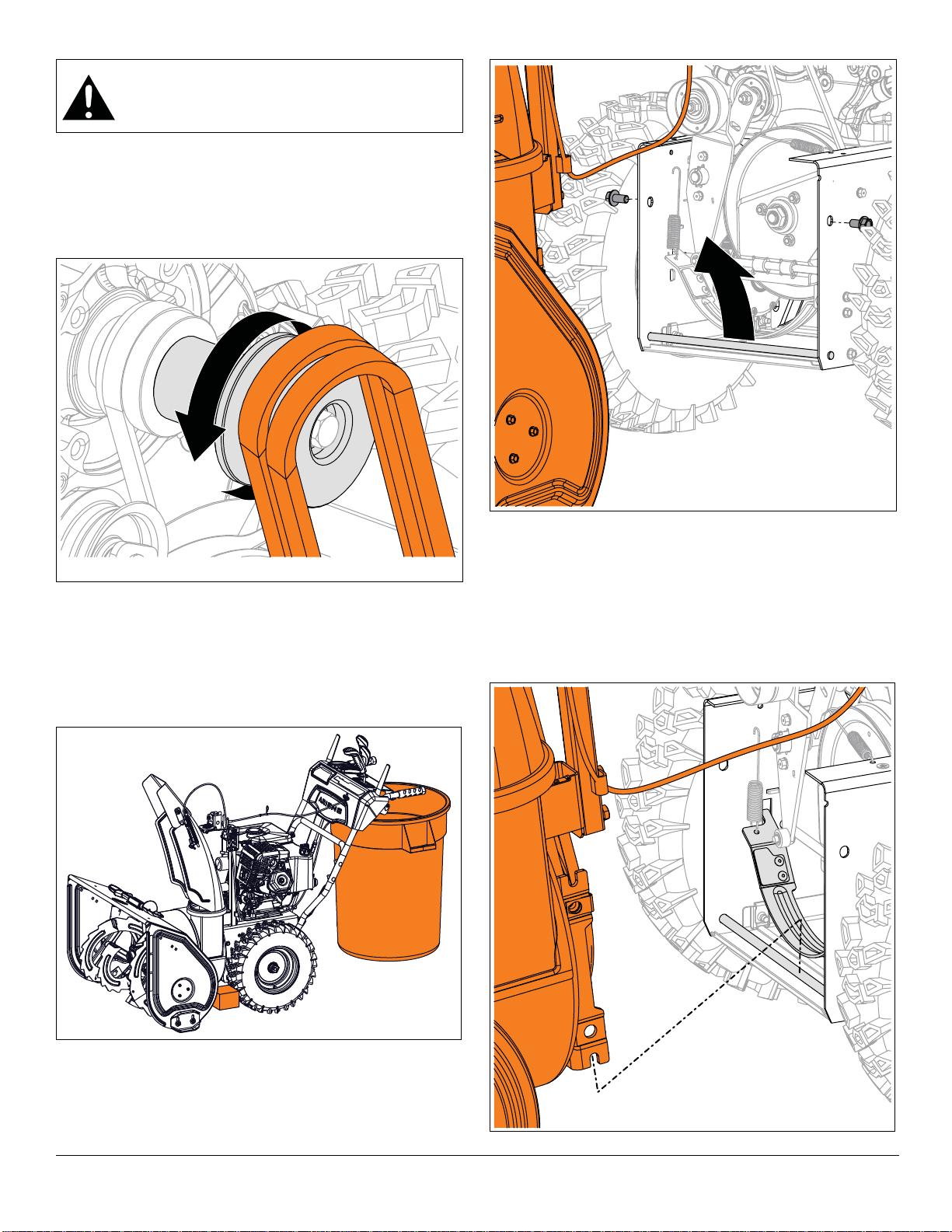
See Figure10.
15. Remove attachment drive belts from attachment
sheave.
To assist belt removal, slowly pull recoil starter handle
while gently guiding belts out of attachment sheave.
See Figure11.
16. Position support, such as a trash can, under
handlebars so tractor / frame remains upright when
separated from auger housing.
17. Chock or block wheels to prevent tractor / frame
movement.
Reinstall Auger Housing
See Figure 13.
1. With assistance from an adult helper, engage
attachment clutch lever so attachment brake will not
obstruct attachment drive pulley in step 2.
2. Tilt auger housing rear up and lower mount brackets
onto mount rod.
See Figure12.
18. Remove hardware securing auger housing to frame.
19. Lift auger housing rear slightly to disengage from
mount rod and separate from unit.
EN – 10

3. Release attachment clutch lever.
Figure 14
Figure 15
1. Belt Finger
2. Attachment Drive Belt s
Measure
Here
1
2
4. Align holes in mount brackets with holes in frame and
secure housing to frame with two hex bolts, but DO
NOT tighten.
IMPORTANT: Unit must be on a flat, level surface during
steps 5 – 7.
5. Check tire pressure and adjust if necessary. Refer to
Operator’s Manual for specification.
6. Torque hex bolts installed in step 4 to
33.8 – 70.1 N•m (24.9 – 51.7 lb-ft).
7. Loosen skid shoe hardware and adjust skid shoes.
Refer to Operator’s Manual for adjustment procedure.
See Figure14.
WARNING: AVOID INJURY. Attachment sheave
edges are sharp. Wear thick gloves to install
belts onto attachment sheave.
8. Reinstall attachment drive belts onto attachment
sheave.
To assist belt installation, slowly pull recoil starter handle
while gently guiding belts onto attachment sheave.
See Figure15.
9. Reinstall belt finger and secure with two flat steel
washers, two locking washers and two hex bolts.
10. Check belt finger clearance:
• Engage attachment clutch lever and make sure belt
finger located opposite belt idler is less than 3.2 mm
(1/8") from belt, but not touching the belt.
• If needed, adjust clearance by loosening hex bolts,
repositioning belt finger, and tightening bolts.
11. Reinstall belt cover and secure left side with tapping
screw. Position right side under tapping screw and
tighten.
IMPORTANT: For Model 921326, advance to step 15.
Models 921045, 921046, 921047, 921048, 921049,
921323, 921324, 921325
12. Reinstall short end of chute rotation rod into dash
panel until opposite end clears chute gears.
13. Insert chute rotation rod into chute gear and secure
with spring clip.
14. Advance to step 20.
Model 921326
15. Insert hex rod end without ears into dash panel until
opposite end clears chute gears.
16. Position discharge chute facing forward.
17. Position chute rotation lever upright and insert hex rod
through chute gear until it stops. Secure with hairpin.
18. Insert chute lock cable through hole in dash panel and
insert cable snap into chute control assembly.
19. Remove hairpin from chute control assembly and
reinstall cable eyelet onto assembly. Reinstall hairpin.
See Figure 4.
All Models
20. Reinstall gear cover and secure with tapping screw.
21. Reinstall chute deflector cable into J-clamp on engine
mount.
EN – 11
22. Reinstall deflector cable snap onto deflector anchor.
Figure 16
23. Remove sleeve bushing and hairpin from deflector
arm and reinstall cable eyelet onto deflector arm.
Reinstall sleeve bushing and hairpin. See
Figure 6.Reconnect spark plug wire.
IMPORTANT: Check all adjustments after first use.
WARNING: AVOID INJURY. Auger / impeller
must stop within 5 seconds when attachment
clutch lever is released.
BOTTOM COVER REMOVAL
IMPORTANT: Save all hardware for reinstallation.
WARNING: AVOID INJURY. Before placing unit
in service position, drain fuel from tank and fuel
system. See Draining Fuel System on page 7.
Make sure unit is secure and will not tip.
1. Stop engine, remove key and wait for all moving parts
to stop and for hot parts to cool.
2. Disconnect spark plug wire from engine.
3. Place unit in service position. See Service Pos it i on on
page 7.
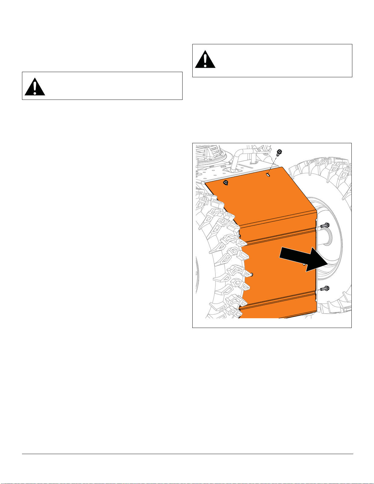
4. Remove hardware retaining bottom cover to frame
and remove cover. See Figure 16.
IMPORTANT: For track models, track angle must be in the
“Raised Position” to remove bottom cover. Refer to
Operator’s Manual. See Figure 17.
EN – 12

Install Bottom Cover
Figure 17
Figure 18
1. Reinstall bottom cover and secure with two tapping
screws and four hex bolts.
2. Return unit to operating position.
ATTACHMENT DRIVE BELT REPLACEMENT
Remove Attachment Drive Belts
IMPORTANT: Save all hardware for reinstallation.
1. Stop engine, remove key and wait for all moving parts
to stop and for hot parts to cool.
2. Disconnect spark plug wire from engine.
3. Remove auger housing. See Separate Housing From
Frame on page 7.
4. Remove attachment drive belts from attachment drive
pulley. See Figure 18.
Install Attachment Drive Belts
1. Install belts onto attachment drive pulley.
2. Reinstall auger housing to frame. See Reinstall Auger
EN – 13
Housing on page 10.
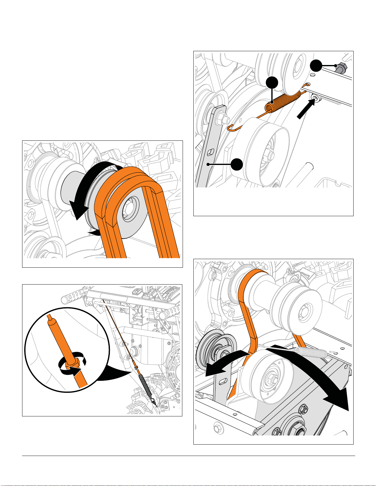
TRACTION DRIVE BELT
Figure 19
Figure 20
Figure 21
1. Idler Spring
2. Traction Idler Arm
3. Stop Bolt
1
2
3
Figure 22
REPLACEMENT
Remove Traction Drive Belt
IMPORTANT: Save all hardware for reinstallation.
1. Stop engine, remove key and wait for all moving parts
to stop and for hot parts to cool.
2. Disconnect spark plug wire from engine.
3. Remove belt cover and belt finger as shown in
Figure 8 and Figure 9.
4. Slowly pull recoil starter handle while gently guiding
attachment belts off engine sheave. See Figure 19.
To assist belt removal, slowly pull recoil starter handle
while gently guiding belts out of attachment sheave.
See Figure 21.
6. Disconnect idler spring from traction idler arm.
7. Remove stop bolt from frame.
5. Loosen traction drive clutch cable. See Figure 20.
See Figure 22.
8. Rotate traction idler arm away from belt and rotate
swing gate assembly forward.
9. Remove belt.
EN – 14
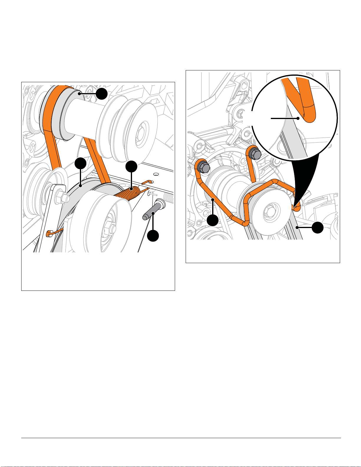
Install Traction Drive Belt
Figure 23
1. Traction Sheave
2. Traction Drive Pulley
3. Stop Bolt
4. Traction Idler Spring
1
2
4
3
Figure 24
1. Belt Finger
2. Attachment Drive Belt s
Measure
Here
1
2
See Figure23.
1. Install belt onto traction sheave and around traction
drive pulley.
2. Return swing gate assembly to upright position and
reinstall stop bolt.
3. Reinstall traction idler spring onto traction idler arm.
6. Check belt finger clearance:
• Engage attachment clutch lever and make sure belt
finger located opposite belt idler is less than 3.2 mm
(1/8") from belt, but not touching the belt.
• If needed, adjust clearance by loosening hex bolts,
repositioning belt finger, and tightening bolts.
4. Reinstall attachment drive belts onto attachment
sheave.
To assist belt installation, slowly pull recoil starter handle
while gently guiding belts onto attachment sheave.
See Figure24.
5. Reinstall belt finger and secure with two flat steel
washers, two locking washers and two hex bolts.
7. Adjust traction drive clutch. Refer to Operator’s
Manual for adjustment procedure.
8. Reconnect spark plug wire.
IMPORTANT: Check all adjustments after first use.
EN – 15

ATTACHMENT BRAKE REPLACEMENT
Figure 25
1. Top Locking Flange Nut
2. Hex Bolt
3. Attachment Brake Arm
4. Extension Spring
1
2
4
3
Figure 26
Attachment Clutch Disengaged / Brake Engaged
1. Brake Pad
2. Brake Roller
1
2
Figure 27
Attachment Clutch Engaged / Brake Disengaged
1. Brake Pad
2. Brake Roller
1
2
Remove Attachment Brake
IMPORTANT: Save all hardware for reinstallation.
1. Stop engine, remove key and wait for all moving parts
to stop and for hot parts to cool.
2. Disconnect spark plug wire from engine.
3. Remove auger housing. See Separate Housing From
Frame on page 7.
See Figure25.
4. Disconnect extension spring from attachment brake
arm.
5. Remove hardware retaining attachment brake arm to
brake mount bracket.
6. Remove brake arm.
See Figures 26 and 27.
3. Engage and disengage attachment clutch to verify
brake roller on attachment idler does not interfere with
brake pad.
IMPORTANT: Make sure brake roller does not bind.
Install Attachment Brake
1. Position pivoting end of attachment brake arm in brake
mount bracket and secure with one hex bolt and top
locking flange nut, but DO NOT overtighten.
2. With flathead screwdriver or similar pry bar, reconnect
extension spring to attachment brake arm.
4. Reinstall auger housing to frame. See Reinstall Auger
Housing on page 10.
EN – 16

WARNING: AVOID INJURY. Before placing unit
Figure 28
1. Brake Pad
2. Attachment Pulley & Belt
1
2
Figure 29
in service position, drain fuel from tank and fuel
system. See Draining Fuel System on page 7.
Make sure unit is secure and will not tip.
5. Place unit in service position and remove bottom
cover. See Service Position on page 7 and Bottom
Cover Removal on page 12.
See Figure28.
6. Check attachment brake:
• When attachment clutch is disengaged, brake must
contact attachment belt or pulley, whichever is
closest.
• When attachment clutch is engaged, brake must be
more than 1.6 mm (1/16”) away from attachment belt
or pulley, whichever is closest.
IMPORTANT: If attachment clutch / brake is out of
adjustment, refer to Operator’s Manual for adjustment
procedure.
FRICTION DISC REPLACEMENT
Remove Friction Disc
IMPORTANT: Save all hardware for reinstallation.
WARNING: AVOID INJURY. Before placing unit
in service position, drain fuel from tank and fuel
system. See Draining Fuel System on page 7.
Make sure unit is secure and will not tip.
1. Stop engine, remove key and wait for all moving parts
to stop and for hot parts to cool.
2. Disconnect spark plug wire from engine.
3. Place unit in service position and remove bottom
cover. See Service Position on page 7 and Bottom
Cover Removal on page 12.
See Figure 29.
4. Remove hairpin securing adjustment pivot pin to shift
arm.
5. Remove adjustment pivot pin from shift arm.
7. Reinstall bottom cover and secure with two tapping
screws and four hex bolts.
8. Return unit to operating position.
9. Reconnect spark plug wire and fill fuel tank.
IMPORTANT: Check all adjustments after first use.
WARNING: AVOID INJURY. Auger / impeller
must stop within 5 seconds when attachment
clutch lever is released.
6. Remove snap clips from axle ends and remove
wheels.
7. Remove hardware securing bearing to left side of
frame and remove bearing. See Figure 30.
EN – 17

8. Remove two spring clips from hex shaft. See
Figure 30
1. Bearing Flange
2. Hex Shaft
3. Bearing
1
2
3
Figure 31
Figure 32
Figure 31.
9. Remove hex shaft from friction disc assembly and
remove friction disc assembly. See Figure 32.
EN – 18

Install Friction Disc
Figure 33
Figure 34
Figure 35
1. Install friction disc assembly around shift fork roller
bearing and align with hex shaft. See Figure 33.
2. Reinstall hex shaft through friction disc, pinion
sprocket and into frame. See Figure 34.
6. Reinstall adjustment pivot pin onto shift arm and
secure with hairpin.
7. Reinstall bottom cover and secure with two tapping
screws and four hex bolts.
8. Reinstall wheels onto axle and secure with snap clips.
9. Return unit to operating position.
10. Fill fuel tank and reconnect spark plug wire.
11. Adjust speed selector lever. Refer to Operator’s
Manual for adjustment procedure.
IMPORTANT: Check all adjustments after first use.
See Figure35.
3. Reinstall spring clips into hex shaft.
4. Reinstall bearing onto hex shaft end.
5. Reinstall bearing flange over bearing and secure to
frame with three tapping screws.
EN – 19

HEX SHAFT BEARING REPLACEMENT
Figure 36
1. Bearing Flange
2. Bearing
3. Hex Shaft
1
2
3
Figure 37
SWING GATE REPLACEMENT
Remove Bearing
IMPORTANT: Save all hardware for reinstallation.
1. Stop engine, remove key and wait for all moving parts
to stop and for hot parts to cool.
2. Disconnect spark plug wire from engine.
See Figure36.
3. Remove hardware retaining bearing flange to frame
and remove flange.
4. Remove bearing from hex shaft.
Remove Swing Gate Assembly
IMPORTANT: Save all hardware for reinstallation.
1. Stop engine, remove key and wait for all moving parts
to stop and for hot parts to cool.
2. Disconnect spark plug wire from engine.
3. Remove auger housing. See Separate Housing From
Frame on page 7.
4. Remove traction drive belt. See Remove Traction
Drive Belt on page 14.
See Figure 37.
5. Position tractor / frame on a support, such as wood
blocks, so wheels are off the ground. Make sure unit is
secure and will not tip.
6. Remove snap clip from axle ends and remove wheels.
Install Bearing
1. Install bearing onto hex shaft end.
2. Install bearing flange over bearing and secure to
frame with three tapping screws.
EN – 20

See Figure38.
Figure 38
1. Traction Drive Clutch Cable
2. Return Spring
1
2
Figure 39
Figure 40
Figure 41
7. Disconnect traction drive clutch cable and return
spring from swing gate.
IMPORTANT: To gain more cable slack, traction drive
clutch cable may need to be removed from traction clutch
lever. See Figure 69.
Install Swing Gate Assembly
8. Remove three hairpins and one flat steel washer from
pivot rod and remove pivot rod. See Figure 39.
WARNING: AVOID INJURY. Wear thick gloves;
traction drive pulley and engine sheave edges
are sharp.
1. Position swing gate assembly inside frame and align
with pivot rod holes.
2. Reinstall pivot rod through swing gate and secure with
one flat steel washer and three hairpins. See
Figure 41.
9. Remove swing gate assembly. See Figure 40.
3. Reconnect traction drive clutch cable and return
spring to swing gate. See Figure 42.
EN – 21

IMPORTANT: If traction drive clutch cable was removed
Figure 42
Figure 43
1. Bearing Pl ate
1
from traction clutch lever, reinstall cable to lever. See
Figure 69.
4. Reinstall traction belt. See Install Traction Drive Belt
on page 15.
5. Reinstall auger housing to frame. See Reinstall Auger
Housing on page 10.
6. Adjust traction drive clutch. Refer to Operator’s
Manual for adjustment procedure.
7. Reconnect spark plug wire.
IMPORTANT: Check all adjustments after first use.
AUGER REPLACEMENT
Remove Auger
IMPORTANT: Save all hardware for reinstallation.
1. Stop engine, remove key and wait for all moving parts
to stop and for hot parts to cool.
2. Disconnect spark plug wire from engine.
3. Remove auger housing. See Separate Housing From
Frame on page 7.
See Figure 43.
CAUTION: AVOID INJURY. Attachment driv e
pulley edges are sharp. Wear gloves when
handling pulley.
4. Hold attachment drive pulley in place and remove
hardware securing pulley to impeller shaft.
5. Remove pulley and spacer from impeller shaft.
6. Loosen, but DO NOT remove hardware securing
bearing plate to auger housing.
EN – 22

7. Remove hardware retaining support bushings to auger
Figure 44
Figure 45
Figure 46
Figure 47
Figure 48
housing. See Figure 44.
8. Remove hardware retaining gearcase support
brackets to housing. See Figure 45.
10. Remove shear bolt from auger shaft. See Figure 47.
9. Remove auger assembly from housing. See
Figure 46.
11. Remove support bushing and flange bushing from
auger shaft end. See Figure 48.
EN – 23

See Figure49.
Figure 49
Figure 50
Figure 51
Figure 52
12. Remove auger. Use of penetrating oil or heat may be
necessary to remove auger.
NOTICE: If rust is present on auger shaft, remove with
sand paper and wipe clean with oil.
5. Reinstall auger assembly into housing so impeller
shaft is seated in ball bearing at housing rear. See
Figure 52.
Install Auger
See Figure50.
1. Install auger onto auger shaft with auger kickers facing
gearcase.
IMPORTANT: Make sure auger helix direction matches the
original auger orientation.
2. Apply grease to grease zerk
3. Align holes in auger with holes in auger shaft and
reinstall shear bolt. Torque bolt to 7.9 – 16.5 N•m
(5.8 – 12.2 lb-ft). If torque wrench is unavailable,
tighten until bolts no longer spin freely. DO NOT
overtighten.
4. Reinstall flange bushing and support bushing onto
auger shaft end. See Figure 51.
EN – 24

6. Secure support brackets to auger housing with two
Figure 53
Figure 54
Figure 55
1. Spacer Bushing
2. Bearing Plate
1
2
round head square neck bolts and two top locking
flange nuts. See Figure 53.
7. Secure support bushings to auger housing with six
tapping screws. See Figure 54.
12. Reinstall housing to frame. See Reinstall Auger
Housing on page 10.
13. Reconnect spark plug wire.
See Figure55.
8. Tighten three hex nuts retaining bearing plate.
9. Apply a thin layer of anti-seize to impeller shaft end.
10. Reinstall spacer bushing onto impeller shaft end.
11. Reinstall attachment drive pulley onto impeller shaft
and secure with locking washer and hex bolt. Torque
to 7.9 – 16.5 N•m (5.8 – 12.2 lb-ft).
EN – 25

AUGER GEARCASE REPLACEMENT
Figure 56
1. Hex Bolt
2. Extension Loc k ing Wash er
3. Support Br ac ke t
1
2
3
Figure 57
Remove Gearcase Assembly
IMPORTANT: Save all hardware for reinstallation.
1. Stop engine, remove key and wait for all moving parts
to stop and for hot parts to cool.
2. Disconnect spark plug wire from engine.
3. Remove augers. See Remov e Aug er on page 22.
See Figure56.
4. Remove hardware retaining support brackets to
gearcase and remove brackets.
5. Remove two flat steel washers from auger shaft.
Install Gearcase Assembly
1. Install impeller onto impeller shaft.
2. Align holes in impeller with holes in impeller shaft and
reinstall roll pins.
3. Reinstall one flat steel washer onto each auger shaft
end.
4. Reinstall support brackets to gearcase and secure
with two extension locking washers and hex bolts. See
Figure 56.
5. Reinstall augers. See Install Auger on page 24.
6. Reconnect spark plug wire.
See Figure57.
6. Remove two roll pins retaining impeller to impeller
shaft and remove impeller.
IMPORTANT: Use of penetrating oil or heat may be
necessary to remove impeller.
EN – 26

IMPELLER REPLACEMENT
Figure 58
1. Bearing Plate
1
Figure 59
Figure 60
Remove Impeller
IMPORTANT: Save all hardware for reinstallation.
1. Stop engine, remove key and wait for all moving parts
to stop and for hot parts to cool.
2. Disconnect spark plug wire from engine.
3. Remove auger housing. See Separate Housing From
Frame on page 7.
See Figure58.
4. Remove hardware securing attachment drive pulley to
impeller shaft.
5. Remove pulley and spacer from impeller shaft.
6. Loosen, but DO NOT remove bearing plate hardware.
Install Impeller
See Figure 59.
1. Apply a thin layer of anti-seize to impeller shaft.
2. Install impeller onto impeller shaft.
7. Remove hardware securing auger bushings to auger
housing. See Figure 44.
8. Remove auger assembly from housing. See
Figure 46.
See Figure57.
9. Remove two roll pins securing impeller to impeller
shaft and remove impeller.
IMPORTANT: Use of penetrating oil or heat may be
necessary to remove impeller.
3. Align impeller with holes in impeller shaft and reinstall
roll pins. See Figure 60.
4. Reinstall auger assembly into housing so impeller
shaft is seated in ball bearing at housing rear. See
Figure 52.
5. Secure support bushings to auger housing with six
tapping screws. See Figure 61.
EN – 27

See Figure62.
Figure 61
Figure 62
1. Spacer Bushing
2. Bearing Plate
1
2
Figure 63
6. Tighten three hex nuts securing bearing plate to
housing.
7. Apply a thin layer of anti-seize to impeller shaft end.
8. Reinstall spacer bushing onto impeller shaft end.
9. Reinstall attachment drive pulley onto impeller shaft
and secure with locking washer and hex bolt. Torque
to 7.9 – 16.5 N•m (5.8 – 12.2 lb-ft).
ENGINE REPLACEMENT
Remove Engine
IMPORTANT: Save all hardware for reinstallation.
1. Stop engine, remove key and wait for all moving parts
to stop and for hot parts to cool.
2. Disconnect spark plug wire from engine.
3. Drain gasoline from fuel system and tank. See
Draining Fuel System on page 7.
4. Remove belt cover. See Figure 8.
5. Remove hardware securing belt finger to engine and
remove belt finger. See Figure 9.
6. Disconnect idler spring from traction drive idler arm
and remove spring. See Figure 63.
10. Reinstall auger housing to frame. See Reinstall Auger
Housing on page 10.
11. Reconnect spark plug wire.
EN – 28

See Figure64.
Figure 64
Figure 65
Figure 66
7. Remove hardware securing engine mount to frame.
8. Remove J-clamp and chute deflector cable from
engine mount.
WARNING: AVOID INJURY. Engine is heavy.
NEVER lift engine without a suitable lifting device
or adult assistant.
Install Engine
WARNING: AVOID INJURY. Engine is heavy.
NEVER lift engine without a suitable lifting device
or adult assistant.
1. Using a suitable lifting device or help from an adult
assistant, lift engine and lower onto bolts in frame.
2. Position belts over crankshaft.
3. Reinstall J-clamp to left rear engine mounting position.
4. Secure engine mount to frame with four locking nuts.
Torque to 11.9 – 17.9 N•m (8.8 – 13.2 lb-ft).
See Figure 66.
5. Reinstall traction sheave onto crankshaft.
6. Reinstall traction drive belt onto traction sheave.
7. Reinstall attachment sheave onto crankshaft.
IMPORTANT: Traction sheave must be reinstalled in the
orientation shown in Figure 66.
9. Using a suitable lifting device or help from an adult
assistant, lift engine and tilt forward slightly to relieve
tension from belts. Remove belts from engine
sheaves.
10. Lower engine onto a flat, level surface.
See Figure65.
11. Remove hardware securing attachment sh eave to
crankshaft.
12. Remove attachment sheave, traction sheave and
nylon washer from crankshaft.
EN – 29

See Figure67.
Figure 67
Figure 68
8. Reinstall idler spring to traction idler arm.
9. Secure attachment sheave to crankshaft with one
locking washer and hex bolt.
11. Reinstall belt finger and secure with two flat steel
washers, two locking washers and two hex bolts as
shown in Figure 9.
12. Check belt finger clearance:
• Engage attachment clutch lever and make sure belt
finger located opposite belt idler is less than 3.2 mm
(1/8”) from belt, but not touching the belt.
• If needed, adjust clearance by loosening hex bolts,
repositioning belt finger, and tightening bolts.
13. Reinstall belt cover and secure left side to frame with
one tapping screw. Position right side of belt cover
under tapping screw and tighten.
14. Reinstall chute deflector cable into J-clamp. Bend
clamp slightly to secure cable in clamp.
15. Reconnect spark plug wire and fill fuel tank.
WARNING: AVOID INJURY. Attachment sheave
edges are sharp. Wear thick gloves to install
belts onto attachment sheave.
See Figure68.
10. Reinstall attachment drive belts onto attachment
sheave.
To assist belt installation, slowly pull recoil starter handle
while gently guiding belts into attachment sheave.
EN – 30

TRACTION DRIVE CABLE
Figure 69
Figure 70
Figure 71
REPLACEMENT
Remove Traction Drive Clutch Cable
IMPORTANT: Save all hardware for reinstallation.
1. Stop engine, remove key and wait for all moving parts
to stop and for hot parts to cool.
2. Disconnect spark plug wire from engine.
3. Loosen traction drive clutch cable.
4. Under dash panel, remove hardware retaining upper
traction clutch cable to clutch lever and remove cable.
See Figure69.
See Figure70.
5. Disconnect lower traction drive cable from upper
traction drive cable.
6. Loosen, but DO NOT remove shoulder bolt retaining
cable pulley to cable pulley bracket.
7. Remove belt cover. See Figure 8.
8. Remove lower traction clutch cable hook from swing
gate. See Figure 71.
9. Remove cable.
EN – 31

Install Traction Drive Clutch Cable
Figure 72
Figure 73
WARNING: AVOID INJURY. Before placing unit
in service position, drain fuel from tank and fuel
system. See Draining Fuel System on page 7.
Make sure unit is secure and will not tip.
1. Rotate unit to service position and remove bottom
cover. See Service Position on page 7 and Bottom
Cover Removal on page 12.
See Figure72.
2. Route cable end with spring hook through hole in back
cover.
3. Install cable end onto swing gate.
6. Reinstall bottom cover and secure with two tapping
screws and four hex bolts.
7. Reinstall upper traction clutch cable to traction clutch
lever. Secure with one flat steel washer and hairpin.
See Figure 69.
8. Return unit to operating position.
9. Adjust traction drive clutch. Refer to Operator’s
Manual for adjustment procedure.
10. Reconnect spark plug wire and fill fuel tank.
IMPORTANT: Check all adjustments after first use.
See Figure73.
4. Align cable with cable pulley and tighten shoulder bolt.
5. Reconnect lower traction clutch cable to upper traction
clutch cable.
EN – 32

DUAL-HANDLE INTERLOCK CAM
Figure 74
1. Spring Clip
2. Interlock Cam
3. Spring
4. Interlock Bracket
1
3
4
2
2
4
1
3
Models 921047, 921049, 921323, 921324,
921325, 921326
Models 921045, 921046, 921048
Figure 75
Models 921045, 921046, 921048
Models 921047, 921049, 921323, 921324,
921325, 921326
REPLACEMENT
Remove Interlock Cam
IMPORTANT: Save all hardware for reinstallation.
See Figure74.
1. Disconnect spring from interlock bracket.
2. Remove two spring clips securing interlock cams to
camshafts.
IMPORTANT: Interlock cams will fall from camshafts in
next step.
3. Remove hard ware retaining ca mshafts to clut ch levers
and remove camshafts. See Figure 75.
4. Remove cams.
EN – 33

Install Interlock Cams
Figure 76
Models 921045, 921046, 921048
Models 921047, 921049, 921323, 921324,
921325, 921326
Figure 77
Models 921045, 921046, 921048
Models 921047, 921049, 921323, 921324,
921325, 921326
IMPORTANT: Make sure nylon bushings are seated in
interlock bracket. See Figure 76.
1. Reinstall right camshaft through interlock bracket and
secure to clutch lever with one tapping screw.
2. Install interlock cam onto camshaft so flat edge is
positioned downward. Secure with spring clip. See
Figure 77.
3. Position left interlock cam inside interlock bracket and
align with left camshaft.
4. Insert camshaft through cam.
5. Secure camshaft to clutch lever with one tapping
screw.
EN – 34

See Figure78.
Figure 78
Models 921045, 921046, 921048
Models 921047, 921049, 921323, 921324,
921325, 921326
Figure 79
6. Rotate cam so flat edge is positioned upward and
secure with spring clip.
7. Reconnect spring to interlock bracket.
AXLE BUSHING REPLACEMENT
Remove Left Axle Bushing
IMPORTANT: Save all hardware for reinstallation.
WARNING: AVOID INJURY. Before placing unit
in service position, drain fuel from tank and fuel
system. See Draining Fuel System on page 7.
Make sure unit is secure and will not tip.
1. Stop engine, remove key and wait for all moving parts
to stop and for hot parts to cool.
2. Disconnect spark plug wire from engine.
3. Place unit in service position and remove bottom
cover. See Service Position on page 7 and Bottom
Cover Removal on page 12.
4. Remove snap clips from left axle end and remove
wheel.
See Figure 79.
5. Remove key and flat steel washer from axle.
6. Remove hardware securing axle bushing to frame and
remove bushing.
8. Check dual-handle interlock function. Refer to
Operator’s Manual for test procedure.
IMPORTANT: If dual-handle interlock continues to
malfunction, see your Ariens dealer.
Install Left Axle Bushing
1. Install bushing onto axle and secu re to frame w ith
three tapping screws from inside frame.
2. Reinstall flat steel washer and key onto axle.
3. Reinstall bottom cover and secure with two tapping
screws and four hex bolts.
4. Reinstall wheel and secure with snap clip.
5. Return unit to operating position.
6. Reconnect spark plug wire and fill fuel tank.
EN – 35

Remove Right Axle Bushing
Figure 80
Figure 81
Figure 82
IMPORTANT: Save all hardware for reinstallation.
WARNING: AVOID INJURY. Before placing unit
in service position, drain fuel from tank and fuel
system. See Draining Fuel System on page 7.
Make sure unit is secure and will not tip.
1. Stop engine, remove key and wait for all moving parts
to stop and for hot parts to cool.
2. Disconnect spark plug wire from engine.
3. Place unit in service position and remove bottom
cover. See Service Position on page 7 and Bottom
Cover Removal on page 12.
4. Remove snap clips from axle ends and remove
wheels.
See Figure80.
5. Remove E-ring from axle end.
6. Hold differential gear in place and remove axle from
differential.
See Figure 81.
IMPORTANT: Two flat steel washers will fall when short
axle is removed.
7. Hold differential gear and remove short axle.
8. Remove differential gear.
9. Remove hardware securing axle bushing to frame and
remove bushing. See Figure 82.
EN – 36

Install Right Axle Bushing
Figure 83
Figure 84
Figure 85
Figure 86
1. Secure bushing to frame exterior with three tapping
screws from inside frame. See Figure 83.
See Figure84.
2. Reinstall short axle until a small portion of axle is
through frame.
3. Reinstall two flat steel washers onto axle.
4. Align differential gear with pinion gear and short axle.
Reinstall short axle into differential. See Figure 85.
See Figure 86.
5. Reinstall long axle into differential gear.
6. Reinstall E-ring onto axle end.
7. Reinstall bottom cover and secure with two tapping
screws and four hex bolts.
8. Reinstall wheels and secure with snap clips.
9. Return unit to operating position.
10. Reconnect spark plug wire and fill fuel tank.
EN – 37

FLANGE BUSHING REPLACEMENT
Figure 87
Figure 88
Figure 89
IMPORTANT: Save all hardware for reinstallation.
WARNING: AVOID INJURY. Before placing unit
in service position, drain fuel from tank and fuel
system. See Draining Fuel System on page 7.
Make sure unit is secure and will not tip.
1. Stop engine, remove key and wait for all moving parts
to stop and for hot parts to cool.
2. Disconnect spark plug wire from engine.
3. Place unit in service position and remove bottom
cover. See Service Position on page 7 and Bottom
Cover Removal on page 12.
4. Remove snap clip from right axle end and remove
right wheel.
See Figure87.
5. Remove spring clip from pinion shaft.
6. Move pinion shaft to the right.
IMPORTANT: Flat steel washer on pinion shaft will fall
when shaft is removed.
See Figure 88.
IMPORTANT: Sleeve bushing between pinion gear and
frame will fall when pinion shaft is removed.
7. Remove pinion shaft.
8. Remove pinion gear from chain.
9. Remove flange bushings from pinion gear. See
Figure 89.
EN – 38

Install Flange Bushings
Figure 90
Figure 91
Figure 92
1. Install flange bushings into pinion gear.
See Figure90.
2. Reinstall pinion gear into chain and align with
differential gear.
3. Position sleeve bushing between pinion gear and
frame.
4. Reinstall pinion shaft through frame, sleeve bushing
and pinion gear.
5. Reinstall one flat steel washer onto pinion shaft.
DIFFERENTIAL GEAR REPLACEMENT
Remove Differential Gear
IMPORTANT: Save all hardware for reinstallation.
WARNING: AVOID INJURY. Before placing unit
in service position, drain fuel from tank and fuel
system. See Draining Fuel System on page 7.
Make sure unit is secure and will not tip.
1. Stop engine, remove key and wait for all moving parts
to stop and for hot parts to cool.
2. Disconnect spark plug wire from engine.
3. Place unit in service position and remove bottom
cover. See Service Position on page 7 and Bottom
Cover Removal on page 12.
4. Remove snap clips from axle ends and remove
wheels.
See Figure 92.
5. Remove E-ring from axle end.
6. Hold differential gear in place and remove long axle
from differential.
6. Insert pinion shaft end into left side of frame.
7. Position flat steel washer against pinion gear and
reinstall spring clip. See Figure 91.
8. Reinstall bottom cover and secure with two tapping
screws and four hex bolts.
9. Reinstall wheel and secure with snap clip.
10. Return unit to operating position.
11. Reconnect spark plug wire and fill fuel tank.
EN – 39

See Figure93.
Figure 93
Figure 94
Figure 95
Figure 96
IMPORTANT: Two flat steel washers will fall when short
axle is removed.
7. Hold differential gear in place and remove short axle.
8. Remove differential.
See Figure 96.
4. Reinstall long axle into differential gear.
5. Reinstall E-ring onto axle end.
Install Differential Gear
See Figure94.
1. Reinstall short axle until a small portion of axle is
through frame.
2. Reinstall two flat steel washers onto axle.
3. Align differential gear with pinion gear and short axle.
Reinstall short axle into differential. See Figure 95.
6. Reinstall bottom cover and secure with two tapping
screws and four hex bolts.
7. Reinstall wheels onto axle and secure with snap clips.
8. Return unit to operating position.
9. Reconnect spark plug wire and fill fuel tank.
EN – 40

CHUTE GEAR REPLACEMENT
Figure 97
1. Tapping Screw
2. Chute Gear Cover
3. Spring Clip
4. Chute Rotation Rod
1
2
4
3
Figure 98
Figure 99
1. Flat Steel Washer
2. Friction Washer
1
2
Remove Chute Rotation Gear
Models 921045, 921046, 921047, 921048, 921049,
921323, 921324, 921325
IMPORTANT: Save all hardware for reinstallation
1. Stop engine, remove key and wait for all moving parts
to stop and for hot parts to cool.
2. Disconnect spark plug wire from engine.
See Figure97.
3. Remove hardware retaining chute gear cover and
remove cover.
4. Remove spring clip from chute rotation rod and
remove rod from chute gears.
IMPORTANT: Support discharge chute so it remains
upright.
6. Remove hardware retaining chute rotation gear to
pedestal plate and remove gear. See Figure 99.
5. Remove hardware securing actuation gear bracket to
pedestal plate and remove bracket. See Figure 98.
IMPORTANT: Flat steel washer and friction washer may
remain in original positions. See detailed view in Figure 99.
EN – 41

Remove Chute Rotation Gear
Figure 100
1. Tapping Screw
2. Chute Gear Cover
3. Hairpin
4. Hex Rod
1
2
4
3
Figure 101
1. Center Locking Flange Nut
2. Flange Bushing
3. Hex Bolt
4. Chute Rotation Gear
1
4
3
2
Model 921326
IMPORTANT: Save all hardware for reinstallation
1. Stop engine, remove key and wait for all moving parts
to stop and for hot parts to cool.
2. Disconnect spark plug wire from engine.
3. Position discharge chute facing forward.
See Figure 100.
4. Remove hardware retaining chute gear cover and
remove cover.
5. Remove hairpin from hex rod and remove hex rod
from chute gears.
IMPORTANT: Support discharge chute so it remains
upright.
6. Remove hardware retaining chute rotation gear to
pedestal plate and remove gear. See Figure 101.
Install Chute Rotation Gear
Models 921045, 921046, 921047, 921048, 921049,
921323, 921324, 921325
IMPORTANT: Make sure discharge chute is positioned
forward.
See Figure 102.
1. Position chute rotation gear over chute mount bracket
so edge is square with bracket.
IMPORTANT: Make sure flat steel washer and friction
washer are positioned between chute mount bracket and
pedestal plate. See Figure 99.
2. Insert round head square neck bolt through chute
rotation gear.
3. Install friction plate and compression spring onto
round head square neck bolt and secure with top
locking flange nut.
IMPORTANT: Make sure notch in friction plate aligns with
tab on chute mount bracket.
EN – 42

4. Reinstall actuation gear bracket to pedestal plate and
Figure 102
1. Friction Plate
2. Chute Mount Bracket
1
2
Figure 103
1. Actuation Gear
2. Chute Rotation Gear
3. Chute Lock Arm
4. Calibration Marker s
1
2
3
4
Figure 104
secure with two tapping screws.
5. Reinstall chute rotation rod into chute gear and secure
with spring clip.
6. Reinstall chute gear cover and secure with tapping
screw.
7. Adjust discharge chute. Refer to Operator’s Manual
for adjustment procedure.
8. Reconnect spark plug wire.
IMPORTANT: Check all adjustments after first use.
Install Chute Rotation Gear
Model 921326
IMPORTANT: Make sure discharge chute is positioned
forward.
See Figure 103.
1. Position actuation gear so gear teeth are at lowest
position.
2. Install chute rotation gear so midpoint of gear teeth is
seated in chute lock arm.
IMPORTANT: Make sure calibration markers on actuation
gear and chute rotation gear align.
3. Secure chute rotation gear with one hex bolt, one
flange bushing and locking nut. See Figure 104.
4. Position chute rotation lever upright and discharge
chute facing forward.
EN – 43

5. Reinstall hex rod into chute gears and secure with
Figure 105
1. Tapping Screw
2. Chute Gear Cover
3. Spring Clip
4. Chute Rotation Rod
1
2
4
3
Figure 106
1. Push Nut
2. Actuation Gear
1
2
Figure 107
hairpin.
6. Reinstall chute gear cover and secure with tapping
screw.
7. Adjust discharge chute. Refer to Operator’s Manual
for adjustment procedure.
8. Reconnect spark plug wire.
IMPORTANT: Check all adjustments after first use.
Remove Actuation Gear
Models 921045, 921046, 921047, 921048, 921049,
921323, 921324, 921325
IMPORTANT: Save all hardware for reinstallation.
1. Stop engine, remove key and wait for all moving parts
to stop and for hot parts to cool.
2. Disconnect spark plug wire from engine.
See Figure 105.
3. Remove hardware retaining chute gear cover to chute
pedestal and remove cover.
4. Remove spring clip from chute rotation rod and
remove rod from chute gears.
7. Remove actuation gear from actuation gear bracket.
8. Remove flat steel washer from actuation gear.
Remove Actuation Gear
Model 921326
IMPORTANT: Save all hardware for reinstallation.
1. Stop engine, remove key and wait for all moving parts
to stop and for hot parts to cool.
2. Disconnect spark plug wire from engine.
3. Remove chute rotation gear. See Remove Chute
Rotation Gear on page 42.
See Figure 107.
4. Remove actuation gear and two flat steel washers
from chute gear bracket.
5. Remove hardware securing actuation gear bracket to
pedestal plate and remove bracket. See Figure 98.
See Figure 106.
6. Remove push nut from actuation gear and discard.
EN – 44

Install Actuation Gear
Figure 108
Figure 109
Models 921045, 921046, 921047, 921048, 921049,
921323, 921324, 921325
1. Install one flat steel washer onto actuation gear and
insert gear through actuation gear bracket.
2. Install push nut onto actuation gear so it is tight
against actuation gear bracket.
3. Reinstall actuation gear bracket to pedestal plate and
secure with two tapping screws.
4. Reinstall chute rotation rod into chute gear and secure
with spring clip.
5. Reinstall chute gear cover and secure with tapping
screw.
6. Adjust discharge chute. Refer to Operator’s Manual
for adjustment procedure.
7. Reconnect spark plug wire.
IMPORTANT: Check all adjustments after first use.
Install Actuation Gear
Model 921326
1. Install two flat steel washers onto actuation gear.
2. Install actuation gear into chute gear bracket.
3. Reinstall chute rotation gear. See Install Chute
Rotation Gear on page 43.
SCRAPER BLADE REPLACEMENT
Remove Scraper Blade
IMPORTANT: Save all hardware for reinstallation.
WARNING: AVOID INJURY. Before tipping unit
onto handlebars, drain fuel from tank and fuel
system. See Draining Fuel System on page 7.
Make sure unit is secure and will not tip.
1. Stop engine, remove key and wait for all moving parts
to stop and for hot parts to cool.
2. Disconnect spark plug wire from engine.
3. Remove hardware securing scraper blade ends to
auger housing. See Figure 108.
See Figure 109.
4. Slowly tip unit back so it rests on handlebars.
5. Remove remaining hardware securing scraper blade
to auger housing and remove scraper blade.
EN – 45

Install Scraper Blade
Figure 110
Figure 111
1. Position scraper blade inside auger housing and align
with holes in housing.
2. Insert seven flat head square neck bolts through
scraper blade from inside housing. Secure with seven
top locking flange nuts.
3. Insert two round head square neck bolts through
scraper blade ends and skid shoes from inside
housing. Secure with two flat steel washers and two
hex nuts.
4. Return unit to operating position.
5. Adjust scraper blade and skid shoes. Refer to
Operator’s Manual for adjustment procedures.
6. Reconnect spark plug wire and fill fuel tank.
IMPORTANT: Check all adjustments after first use.
HEADLIGHT REPLACEMENT
Remove Bulb
IMPORTANT: Save all hardware for reinstallation.
1. Stop engine, remove key and wait for all moving parts
to stop and for hot parts to cool.
2. Disconnect spark plug wire from engine.
3. Remove hardware securing headlight to dash panel.
See Figure 110.
See Figure 111.
4. Remove headlight from dash panel.
5. Disconnect wire harness from bulb.
6. Turn bulb one-eighth turn counterclockwise and
remove from headlight housing. See Figure 112.
EN – 46

Install Bulb
Figure 112
Figure 113
NOTICE: DO NOT touch new bulb with bare hands; wear
gloves. Body oil on a headlight bulb can increase bulb
temperature and reduce life of the bulb.
1. Install bulb into headlight housing and turn one-eighth
turn clockwise.
2. Connect bulb to wire harness.
3. Reinstall headlight housing into dash panel and
secure with two tapping screws.
IMPORTANT: Reconnect spark plug wire.
GEARCASE REBUILD
Disassemble Gearcase
IMPORTANT: Save all parts for reassembly, unless
otherwise specified.
1. Remove gearcase. See Remove Gearcase Assembly
on page 26.
2. Remove any rust, if present, from auger and impeller
shafts with sandpaper. Wipe clean with oil.
3. Remove drain plug and seal washer from gearcase.
See Figure 113.
EN – 47

See Figure 114.
Figure 114
Figure 115
Figure 116
Figure 117
4. Remove hardware retaining gearcase cover and
remove cover.
5. Remove gasket and drain gearca se .
6. Remove bushing retainer from gearcase. See
Figure 115.
See Figure 116.
7. Press auger shaft through the right side of gearcase.
NOTICE: DO NOT strike auger shaft end; use a press.
8. Remove seal, bushing and washer from auger shaft.
9. With a flathead screwdriver or similar pry bar, remove
front seal cover and discard. See Figure 117.
EN – 48

10. With a snap ring pliers, remove retaining ring. See
Figure 118
Figure 119
Figure 120
Figure 121
Figure 118.
14. Remove seals and flange bushings from gearcase.
See Figure 120.
See Figure 119.
11. With a driver, strike impeller shaft end until shaft is
through front of gearcase.
NOTICE: DO NOT strike impeller shaft end without using a
driver.
12. Remove pin and bushing from impeller shaft.
Assemble Gearcase
See Figure 121.
1. Press rear seal into gearcase until flush with gearcase
exterior.
2. Reinstall right and rear flange bushings.
13. Remove impeller shaft from gearcase and remove all
loose parts from inside gearcase.
EN – 49
IMPORTANT: Gear is symmetrical and may be installed in
either orientation.
3. Install gear into gearcase.

See Figure 122.
Figure 122
Figure 123
Figure 124
4. Reinstall impeller shaft through gearcase front and
reinstall thrust collar onto impeller shaft end.
5. Wrap a seal protector over impeller shaft end and
reinstall shaft through gearcase seal. Remove seal.
NOTICE: Unprotected seals can be damaged when
installed over rough edges in shaft, such as holes.
See Figure 123.
6. Reinstall pin into impeller shaft. Turn shaft so pin is
horizontal.
7. Reinstall thrust collar over pin and position impeller
shaft as far to gearcase rear as possible.
8. Reinstall flange bushing onto impeller shaft end. With
a driver, strike bushing until positioned just below
retaining ring groove. See Figure 124.
9. Reinstall retaining ring. See Figure 125.
EN – 50

10. Turn impeller shaft by hand to make sure shaft rotates
Figure 125
Figure 126
Figure 127
Figure 128
easily.
See Figure 126.
11. Reinstall one flat steel washer into left side of
gearcase.
12. Align washer with gearcase hole and reinstall auger
shaft through gear.
IMPORTANT: Make sure auger shaft key aligns with gear
keyway.
See Figure 127.
13. Reinstall one flat steel washer and bushing onto right
auger shaft end.
IMPORTANT: Stepped-down side of bushing MUST be
positioned toward gearcase.
14. With a driver, such as a 1 1/4” deep-well socket, drive
bushing into gearcase until groove is just beyond
interior gearcase wall. See Figure 128.
EN – 51

See Figure 129.
Figure 129
Figure 130
Figure 131
15. Wrap seal protector around each auger shaft end so
they cover the shear bolt holes.
NOTICE: Unprotected seals can be damaged when
installed over rough edges in shaft, such as holes.
16. Install gearcase seals over seal protectors and press
into gearcase until each seal is flush with gearcase
exterior.
17. Remove seal protectors.
See Figure 131.
20. Reinstall gearcase gasket.
21. Secure cover to gearcase with four external tooth
locking washer bolts.
18. Turn auger shaft by hand to make sure shaft rotates
easily.
19. Reinstall bushing retainer into flange bushing groove.
See Figure 130.
See Figure 132.
22. Press a new front cover into gearcase.
23. Add gearcase oil. Oil level MUST be 6.1 – 6.7 cm
(2.4 – 2.6”) from the flat surface of the gearcase cover.
IMPORTANT: Ariens recommends using only Ariens L3
synthetic severe duty gear lube. Using other lubricants will
not automatically void unit warranty, but the warranty will
not cover damage caused by using unauthorized
lubricants. Refer to the Operator’s Manual for your unit for
the service part numbers.
24. Reinstall seal washer (rubber side down) and oil fill
plug. Torque to 9 N•m (80 lb-in). DO NOT over-torque.
EN – 52

TRACK DRIVE WHEEL REPLACEMENT
Figure 132
Figure 133
Model 921326
Remove Track Drive Wheel
IMPORTANT: Save all hardware for reinstallation.
WARNING: AVOID INJURY. Before placing unit
in service position, drain fuel from tank and fuel
system. See Draining Fuel System on page 7.
Make sure unit is secure and will not tip.
1. Stop engine, remove key and wait for all moving parts
to stop and for hot parts to cool.
2. Disconnect spark plug wire from engine.
3. Place unit in service position. See Service Pos it i on on
page 7.
4. Remove flange nuts from eye bolts around rear track
axle to release track tension. See Figure 133.
See Figure 134.
5. Remove snap clip retaining track drive wheel to drive
axle and remove drive wheel.
IMPORTANT: Be aware of key on axle ends. If key is
removed, reinstall key.
EN – 53

Install Track Drive Wheel
Figure 134
Figure 135
Figure 136
1. Install track drive wheel onto axle.
2. Align drive wheel with track center and secure with
snap ring.
See Figure 135.
3. With assistance from an adult helper, pull rear track
axle up so eye bolts insert through tension brackets.
Secure with center locking flange nuts.
TRACK REPLACEMENT
Model 921326
Remove Track
IMPORTANT: Save all hardware for reinstallation.
WARNING: AVOID INJURY. Before placing unit
in service position, drain fuel from tank and fuel
system. See Draining Fuel System on page 7.
Make sure unit is secure and will not tip.
1. Stop engine, remove key and wait for all moving parts
to stop and for hot parts to cool.
2. Disconnect spark plug wire from engine.
3. Place unit in service position. See Service Pos it i on on
page 7.
4. Remove track drive wheel. See Remove Track Drive
Wheel on page 53.
5. Remove track from carriage assembly. Se e
Figure 136.
4. Return unit to operating position.
5. Reconnect spark plug wire and fill fuel tank.
6. Adjust track tension. Refer to Operator’s Manual for
adjustment procedure.
IMPORTANT: Check all adjustments after first use.
EN – 54

Install Track
Figure 137
1. Bogie Wheel
2. Track Runner
1
2
Figure 138
See Figure 137.
IMPORTANT: Tracks are directional and MUST be installed
with treads in the orientation shown in Fi gur e 137.
1. Install track onto carriage assembly so bogie wheels
and track runner are seated in track center.
2. Reinstall track drive wheel. See Install Track Drive
Wheel on page 54.
BOGIE WHEEL REPLACEMENT
Model 921326
Remove Bogie Wheel
IMPORTANT: Save all hardware for reinstallation.
WARNING: AVOID INJURY. Before placing unit
in service position, drain fuel from tank and fuel
system. See Draining Fuel System on page 7.
Make sure unit is secure and will not tip.
1. Stop engine, remove key and wait for all moving parts
to stop and for hot parts to cool.
2. Disconnect spark plug wire from engine.
3. Place unit in service position. See Service Pos it i on on
page 7.
4. Remove track. See Remove Track on page 54.
5. Remove hex nut securing bogie wheel to track axle
and remove bogie wheel. See Figure 138.
3. Return unit to operating position.
4. Reconnect spark plug wire and fill fuel tank.
5. Adjust track tension. Refer to Operator’s Manual for
adjustment procedure.
IMPORTANT: Check all adjustments after first use.
Install Bogie Wheel
1. Install bogie wheel onto track axle and secure with hex
nut, but DO NOT overtighten.
IMPORTANT: Bogie wheel should spin freely.
2. Reinstall track. See Install Track on page 55.
3. Return unit to operating position.
4. Adjust track tension. Refer to Operator’s Manual for
adjustment procedure.
5. Reconnect spark plug wire.
IMPORTANT: Check all adjustments after first use.
EN – 55

TRACK BEARING REPLACEMENT
Figure 139
Figure 140
Figure 141
Model 921326
Remove Bearing From Left Side of Unit
IMPORTANT: Save all hardware for reinstallation.
WARNING: AVOID INJURY. Before placing unit
in service position, drain fuel from tank and fuel
system. See Draining Fuel System on page 7.
Make sure unit is secure and will not tip.
1. Stop engine, remove key and wait for all moving parts
to stop and for hot parts to cool.
2. Disconnect spark plug wire from engine.
3. Place unit in service position. See Service Position on
page 7.
4. Remove tracks. See Remove Track on page 54.
5. Remove bo ttom co ver. See Bottom Cover Removal on
page 12.
See Figure 139.
6. Remove E-ring from axle end.
7. Hold differential gear in place and remove long axle
from differential.
9. Loosen, but DO NOT remove hardware securing
mount plates to carriage side plates. See Figure 141.
IMPORTANT: Loosen mount plates on both sides of unit.
See Figure 140.
8. Remove axle.
IMPORTANT: Be aware of flat steel washer on axle.
10. Remove sleeve bushing seated between bearing
flanges on side plate and frame. See Figure 142.
EN – 56

11. Remove hardware retaining bearing flange(s) and
Figure 142
Figure 143
1. Bearing Flange
2. Bearing Plate
1
2
Figure 144
Figure 145
remove flange(s).
IMPORTANT: Bearing plate is not a wear item and does
not need replacement unless damaged.
3. Reinstall stepped-down end of long axle through side
plate, frame and into differential gear. See Figure 144.
4. Reinstall E-ring onto axle end. See Figure 145.
Install Bearing to Left Side of Unit
IMPORTANT: Bearing plates are ONLY installed with
flange bearings on frame. Bearing plates are NOT installed
with flange bearings on side plates.
1. Install flange bearing and secure with three hex bolts
and three locking nuts. Tighten hardware.
2. Reinstall sleeve bushing between flange bearings on
side plate and frame.
5. Tighten six locking nuts securing mount plates to track
carriage.
6. Reinstall bottom cover and secure with six hex bolts.
7. Reinstall track drive wheels. See Install Track Drive
Wheel on page 54.
8. Reinstall tracks. See Install Track on page 55.
9. Return unit to operating position.
10. Reconnect spark plug wire and fill fuel tank.
11. Adjust track tension. Refer to Operator’s Manual for
adjustment procedure.
IMPORTANT: Check adjustments after first use.
EN – 57

Remove Bearing From Right Side of Unit
Figure 146
Figure 147
Figure 148
IMPORTANT: Save all hardware for reinstallation.
WARNING: AVOID INJURY. Before placing unit
in service position, drain fuel from tank and fuel
system. See Draining Fuel System on page 7.
Make sure unit is secure and will not tip.
1. Stop engine, remove key and wait for all moving parts
to stop and for hot parts to cool.
2. Disconnect spark plug wire from engine.
3. Place unit in service position. See Service Position on
page 7.
4. Remove tracks. See Remove Track on page 54.
5. Remove bo ttom co ver. See Bottom Cover Removal on
page 12.
6. Remove E-ring from axle end and remove axle from
differential, but DO NOT completely remove axle from
unit. See Figure 139.
See Figure 146.
IMPORTANT: Two flat steel washers will fall when short
axle is removed from differential gear.
7. Hold differential gear in place and remove short axle.
8. Remove differential gear.
10. Remove sleeve bushing seated between flange
bearings on side plate and frame. See Figure 148.
IMPORTANT: Make sure sleeve bushings remain in short
axle ends.
See Figure 147.
9. Loosen, but DO NOT remove hardware securing
mount plates to carriage side plates.
IMPORTANT: Loosen mount plates on both sides of unit.
EN – 58

See Figure 149.
Figure 149
1. Bearing Flange
2. Bearing Plate
2
1
Figure 150
Figure 151
11. Remove hardware retaining bearing flange(s) and
remove bearing(s).
IMPORTANT: Bearing plate is not a wear item and does
not need replacement unless damaged.
6. Reinstall long axle into differential gear. See
Figure 151.
Install Bearing to Right Side of Unit
IMPORTANT: Bearing plates are ONLY installed with
bearing flanges on frame. Bearing plates are NOT installed
with bearings on side plates.
1. Install flange bearings and secure with three hex bolts
and three locking nuts. Tighten hardware.
2. Reinstall sleeve bushing between flange bearings on
side plate and frame.
See Figure 150.
3. Reinstall short axle until a small portion of axle is
through frame.
4. Reinstall two flat steel washers onto short axle.
5. Align differential gear with pinion gear and short axle
and reinstall axle into differential.
7. Reinstall E-ring onto axle end.
8. Tighten six locking nuts securing mount plates to track
carriage.
9. Reinstall bottom cover and secure with six hex bolts.
Tighten hardware.
10. Reinstall track drive wheels. See Install Track Drive
Wheel on page 54.
11. Reinstall tracks. See Install Track on page 55.
12. Return unit to operating position.
13. Reconnect spark plug wire and fill fuel tank.
14. Adjust track tension. Refer to Operator’s Manual for
adjustment procedure.
IMPORTANT: Check all adjustments after first use.
EN – 59

EFI REPLACEMENT COMPONENTS
Figure 152
Red LED
Green LED
14-Pin Chassis
Harness
12-Pin Throttle
Body Harness
Barometric
Pressure Sensor
Air Temperature
Sensor
Figure 153
ECU
EFI TROUBLE CODE IDENTIFICATION
See Figure 152.
Model 921049
Ariens recommends using only genuine Ariens
replacement parts on this unit. Using unauthorized parts
may adversely affect the performance, durability or safety
of this unit and may void the warranty. Click the Parts
Diagrams by Parts Radar link at www.ariens.com for
replacement part numbers of the items listed below:
•ECU
- Barometric P re s s u re S ens o r
- Air Temperature Sensor
• Throttle Body Assembly
- Throttle Plate S ervo Motor
- Fuel Injecto r
- Fuel Pressure Sensor
- Engine Temperature Sensor
• Battery
• Fuel Pump
• Inline Fuel Filter
IMPORTANT: Replacement part sub components are not
available as individual parts.
Trouble
Code
16 Low Battery Voltage Check chargin g
21 Barometer Pressure
22 Engine Temperature
27 Low Fuel Pressure Check fuel level.
28 High B att e ry V ol t age Check charging
Green LED
is Constant
(not
blinking)
LEDs are
dim.
No LEDs
Illuminated
Problem Correction
system and battery.
Replace ECU.
Sensor Failure
Check engine
Sensor Failure
Low Battery Voltage
or Faulty ECU
Low Battery Voltage Check battery voltage
No Battery Voltage Check battery voltage
temperature sensor
and wiring.
systems.
Check battery
voltage. If voltage is
7.2 – 8.4 volts DC,
replace ECU.
If battery measures
lower than 7.2 volts
DC, charge battery.
and charging system.
Battery should
measure 7.2 – 8.4
volts DC.
and charging system.
Battery should
measure 7.2 – 8.4
volts DC.
EN – 60

CHECKING TROUBLE CODES
Figure 154
Figure 155
TROUBLE CODE DIAGNOSTICS
The blinking red LED light on the ECU displays trouble
codes. Its sequence indicates a particular system
malfunction by blinking as many times as the first digit of a
trouble code, pausing, and then blinking as many times as
the second digit of a trouble code.
For example, the red LED will indicate low fuel pressure
(27) by blinking twice, pausing, and blinking seven more
times.
IMPORTANT: Be aware that more than one trouble code
may be present.
A blinking green LED indicates the ECU processor is
operating correctly, even if a sub-component of the ECU
(e.g.: barometric pressure sensor) has failed. A constant
illuminated green (not blinking) LED indicates the ECU may
be experiencing a low battery voltage condition or need
replacement. See EFI Trouble Code Identification on
page 60.
Visually inspect the red LED to verify trouble codes.
To read trouble codes more easily, place a mirror under the
ECU to view LED reflection.
IMPORTANT: If no trouble code is present, but engine is
not operating normally, See Diagnostics for Non-Trouble
Codes on page 64.
NOTICE: Before performing diagnostic tasks, be aware of
the screw on the bottom of the throttle body that adjusts the
servo offset. The servo offset calibrates the throttle body at
the factory using a flow bench and should NEVER be
touched. If it is tampered with, the engine will run poorly
and void the warranty. See Figure 155.
Code 16: Low Battery Voltage
1. Charge the battery. Refer to Operator’s Manual.
2. Start the engine. Refer to Operator’s Manual.
3. Check charging system at the battery.
a. With a multi-meter set to volts DC, back probe the
battery terminals. At full throttle (3600 RPM), the
reading should be 7.5 – 8.4 volts DC.
If voltage measures less than 7.5 volts, check charging
system at the engine. Advance to step 5.
IMPORTANT: If the engine is cold, it is normal for the
engine speed to be 100 – 200 RPM higher until operating
temperature is reached.
4. Stop the engine. Refer to Operator’s Manual.
b. Check the battery. With the engine off, the battery
voltage should be 7.2 – 8.4 volts DC. See Figure 156.
If voltage measures less than 7.2 volts after charging,
replace battery.
EN – 61

5. Back probe the engine stator output connector. See
Figure 156
Figure 157
Stator
Connector
Figure 158
Temperature
Sensor
Figure 157.
a. Start the engine. Refer to Operator’s Manual.
b. A t full throttl e (3600 RPM ), the sta tor output MUST
be 11.5 – 14 volts AC.
If AC voltage measure less than 11.5 volts, remove
flywheel and replace stator.
If stator output is within range and battery is not charging,
check ECU wiring for damage. Replace ECU if necessary.
Code 21: Barometer Sensor
See Figure 152.
This trouble code indicates the barometric pressure sensor
has failed. When the barometric sensor fails, the engine will
not adjust to altitude changes, but will continue to operate
at a default altitude of 800 feet above sea level.
Engine may continue to operate with a failed barometric
pressure sensor, but may not operate at optimal
performance. If barometric pressure sensor fails, replace
ECU.
Code 22: Engine Temperature Sensor
See Figure 152.
If the sensor is damaged or has failed, the engine may not
run smoothly because the ECU cannot adjust for engine
temperature changes.
The temperature sensor and engine components can be
visually inspected for engine temperature issues:
1. Check engine cooling fan and engine cooling fins for
debris or damage.
2. Check the temperature sensor wiring from the throttle
body to the mounting boss on the side of the cylinder.
Make sure connection is secure. See Figure 158.
3. Check wiring and connection from the throttle body to
the ECU for damage.
If no damage is visible, replace throttle body assembly.
EN – 62

Code 27: Low Fuel Pressure
Figure 159
Inline Fuel Filter
Figure 160
Fuel Pump Wires
Figure 161
Low fuel pressure is usually a result of an empty fuel tank,
but could also be from a clogged fuel filter or faulty fuel
pump.
Attempt engine start and check for trouble code reoccurrence after each of the following steps. Refer to
Operator’s Manual for engine starting instructions.
1. Check fuel level and fill fuel tank completely if not
already full.
2. Check fuel lines to ensure there are no leaks or kinks.
3. Check inline fuel filter for debris and blockage. See
Figure 159.
CAUTION: AVOID INJURY. Fuel lines are
pressurized; wear safety glasses.
4. Check fuel pump wiring to ensure it is connected
correctly. See Figure 160.
See Figure 161.
5. Remove the fuel pump wires, turn ignition key to the
ON position and measure the fuel pump voltage.
Voltage output should measure 7.2 – 8.4 volts DC.
IMPORTANT: Fuel pump voltage MUST be measured
within 30 seconds of the ignition switch being turned to the
ON position.
If voltage measures less than 7.2 volts, check the battery
voltage by probing the green wire on the ECU 12-pin
connector. See Figure 162.
• If low voltage or no voltage is present, replace the
ECU.
• If voltage is present, inspect the green wire between
the 12-pin connector and throttle body for a pinched
or broken wire. If the wire has no damage, replace
the throttle body assembly.
• If voltage measures 7.2 – 8.4 volts, turn ignition key
to OFF position, reconnect fuel pump wires and turn
key back to ON position. Fuel pump should make a
“humming” noise.
If fuel pump is silent, the pump may have failed. Check fuel
pump:
1. Drain fuel from fuel system and tank. See Draining
Fuel System on page 7.
2. Remove pump from tank.
3. Reconnect pump wires.
4. Turn the ignition key to the ON position and listen for a
“humming” noise.
If fuel pump is silent, replace fuel pump.
If voltage is within range and fuel pump is operating
normally, the fuel pressure sensor is defective. Replace the
throttle body assembly. S ee Figure 16 7.
EN – 63

Code 28: High Battery Voltage
Engine Temperature
Potentiometer
Servo -
Servo +
B-
Injector-
1
2
3
4
5
6
Ext-ANA- (Potentiometer)
Fuel Pressure Input
Servo-Signal
Ext-ANA+ (Potentiometer)
ECU+
Pump-
7
8
9
10
11
12
Pink
Blue
Yellow
Yellow
Red
Green
Red
Figure 162
This trouble code will activate if ECU detects a higher
voltage from the stator.
1. Start the engine. Refer to Operator’s Manual.
2. Set a multi-meter to volts AC and probe the red and
black stator connector wire. The output should be
11.5 – 14 volts AC at full throttle (3600 RPM).
If stator output measures over 14 volts, replace stator. If
output is within range, advance to step 3. See Figure 157.
IMPORTANT: If the engine is cold, it is normal for the
engine speed to be 100 – 200 RPM higher until operating
temperature is reached.
3. Set a multi-meter to volts DC and probe the battery
connector at the battery terminals. With the engine
running at full throttle (3600 RPM), the output should
be 7.2 – 8.4 volts DC.
If DC output is higher than 8.4 volts, replace ECU. See
Figure 156.
If DC output is within range and red trouble code persists,
replace ECU.
DIAGNOSTICS FOR NON-TROUBLE CODES
Engine Starts and Loses Power
If the engine starts and loses power immediately, this is
usually an indication that the ECU does not detect an RPM
signal. The RPM signal is generated by the stator, which
also powers the hand warmers, headlight and charges the
ECU battery.
A common cause for RPM signal failure may be a ground
short in the AC output wire coming from the stator to the
ECU. Another possible cause may be a defect in the
engine-charging system.
Engine No-Start Condition
If the engine does not start, check for system power.
1. Check spark plug.
2. Check the battery. Battery should have 7.2 – 8.4 volts
If battery measures below specification after charging,
replace battery.
3. Check the ECU status. With battery voltage between
IMPORTANT:
LEDs may appear dim or will not illuminate red or
green LEDs.
EFI Trouble Code Identification on page 60.
4. Check fuel pump output.
EN – 64
a. Stop engine, remove key and wait for all moving parts
to stop and for hot parts to cool.
b. Disconnect the spark plug cap and remove debris
from the spark plug area.
c. Remove spark plug.
d. Inspect the spark plug. Spark plug gap MUST be
0.7 – 0.8 mm (0.027 – 0.030”). Replace if the
electrodes are worn or if the insulator is cracked or
chipped.
e. Position spark plug against engine block and pull
recoil starter handle to check for spark. If no spark is
present, replace spark plug.
f. Reinstall spark plug and finger tighten. Turn an
additional 1/4 turn after spark plug is seated.
g. Reinstall spark plug cap and make sure it is correctly
positioned onto the spark plug.
DC, depending on when the battery was most recently
charged. Extremely low voltage could cause a no-start
condition without triggering a trouble code. If battery
has low voltage, connect battery charger to battery.
Also check the inline fuse on the battery cable.
7.2 – 8.4 volts DC, check if the green ECU status light
is blinking at a consistent rate.
If battery measures below 7.0 volts, ECU
If green LED is constant, (not-blinking) see
a. Remove the heater box.
b. Check voltage at fuel pump. See Code 27: Low Fuel
Pressure on page 63 for voltage readings.
c. Remove fuel hose from fuel pump outlet and attach a
suitable length of fuel hose to the fuel pump outlet
that can safely reach a clearly marked fuel container.

d. With battery voltage between 7.2 – 8.4 volts DC, turn
Figure 163
Pre-
Filter
Figure 164
Gray
Slide
Figure 165
the key to the ON position for 10 seconds to pump
fuel into the container. Fuel should measure
approximately 160 mL (5 oz.).
If fuel amount measures less than 160 mL, remove the fuel
pump and check the pre-filter for blockage. If filter is clean,
replace fuel pump. See Figure 163.
b. Set a multi-meter to volts DC and probe each
terminal with the red probe and contact the black
probe to engine block. With the ignition key in the ON
position, each terminal should measure
7.2 – 8.4 volts DC. See Figure 165.
If voltage is within range and the fuel injector is not
operating correctly with the key in the ON position, replace
throttle body assembly .
IMPORTANT: If replacing fuel pump, wet the fuel system:
a. Fill fuel tank full.
b. Cycle ignition key to the ON position, then to the OFF
position. Repeat.
IMPORTANT: Cycling the ignition key multiple times may
inject excessive amounts of fuel into the throttle body and
“flood” the engine. A flooded engine may require more
starting attempts than normal.
5. Remove connector to the injector.
a. Move gray slide upward until it stops. Gently
compress gray slide and remove connector. See
Figure 164.
EN – 65

c. If no voltage is present at the injector, check voltage
Figure 166
Figure 167
at both the red and white wires on the12-pin ECU
connector. See Figure 166.
If no voltage is present at the ECU, replace ECU. If voltage
is present at the ECU, check wires for kinks or damage. If
damage is present repair wires if possible, or replace
throttle body. See Figure 167.
Surging Run Condition
If the AC output wire from the engine charging system is
damaged, it may cause an intermittent short. This will result
in erratic running such as the engine over revving or
“popping” through the exhaust.
1. Check the engine wiring and wiring under the
handlebar to verify that it is not damaged.
Engine Speed Does Not Change
If engine speed does not change when using the
potentiometer (throttle control), check the following:
1. Set a multi-meter to ohms and measure the
potentiometer resistance. See Figures 168 and
Figure 169.
a. Unplug the 14-pin connector from the ECU.
b. Position the red probe on the terminal of the red wire
at the potentiometer (Pin 5 in Figure 168) and the
black probe on the terminal of the
green / white wire.
The potentiometer output should measure 0 – 5000 ohms.
If ohm reading measures close to 0 at full throttle and close
to 5000 at low-idle, potentiometer is operating normally. If
ohm reading stays constant at either position, replace
potentiometer.
EN – 66

Engine Connector 1
Yellow
Yellow
Figure 168
Figure 169
Figure 170
Battery Connector 1
Red
Green
Potentiometer 2
Ignition Key Switch 2
Yellow
14
13
12
11
10
9
8
7
Battery Connector 2
Engine Connector 2
6
Potentiometer 3
5
Potentiometer 1
4
3
Ignition Key Switch 1
2
1
Red
Yellow
2. With a multi-meter, measure the volts DC of the red
wire.
a. With engine off, reconnect the 14-pin connector to
the ECU.
b. Position the red probe on the terminal of the red wire
at the potentiometer (Pin 5 in Figure 168). Also see
Figure 169.
c. Position the black probe on the engine block.
d. Turn ignition key to ON position.
e. Turn the potentiometer from low-idle to full throttle.
Voltage to the red wire should measure 4.90 – 5.0 volts DC
at both low-idle and full throttle positions.
If voltage measures less than 4.90, replace ECU.
3. With a multi-meter, measure the volts DC of the
green / white wire. See Figure 170.
a. With engine off, position the red probe on the
terminal of the green / white wire.
b. Position the black probe on the engine block.
c. Turn ignition key to ON position.
d. Turn the potentiometer from low-idle to full throttle.
Voltage to the green / white wire should measure close to
0.01 volts DC at low-idle and close to 5.0 volts at
full throttle.
If voltage does not vary between low-idle and
full throttle, replace the ECU.
EN – 67

SERVICE RECORD
DATE SERVICE PERFORMED NOTES
EN – 68


655 West Ryan Street
Brillion, WI 54110
ariensstore.com
ariens.custhelp.com
parts.ariens.com
T
E
N
I
D
R
P
 Loading...