

Page 1
939 Sno-Thro
Service Manual
Models 939001, 939002, 939300
01920500 12/06
Printed in USA
Page 2

TABLE OF CONTENTS
1.0 Introduction . . . . . . . . . . . . . . . . . . . . . . .1-5
1.1 The Manual . . . . . . . . . . . . . . . . . . . . . . .1-5
1.2 Service and Replacement Parts . . . . . . .1-5
1.3 Product Registration . . . . . . . . . . . . . . . .1-5
1.4 Unauthorized Replacement Parts . . . . . .1-5
1.5 Disclaimer . . . . . . . . . . . . . . . . . . . . . . . .1-5
1.6 Technical Service Communications . . . . .1-5
2.0 Safety . . . . . . . . . . . . . . . . . . . . . . . . . . . .2-6
2.1 Safety Alerts . . . . . . . . . . . . . . . . . . . . . .2-6
2.2 Notations . . . . . . . . . . . . . . . . . . . . . . . . .2-6
2.3 Practices and Laws . . . . . . . . . . . . . . . . .2-6
2.4 Required Operator Training . . . . . . . . . . .2-6
2.5 Safety Decals and Locations . . . . . . . . . .2-6
2.6 Preparation . . . . . . . . . . . . . . . . . . . . . . .2-7
2.7 Service Position . . . . . . . . . . . . . . . . . . . .2-7
2.8 Cleaning and Storage . . . . . . . . . . . . . . .2-8
Safety Rules 8
3.0 Specifications . . . . . . . . . . . . . . . . . . . . . 3-10
4.0 General Maintenance & Adjustments . . 4-11
4.1 Controls and Features . . . . . . . . . . . . . . 4-11
4.2 Service Position . . . . . . . . . . . . . . . . . . . 4-12
4.3 Stopping in an Emergency . . . . . . . . . . . 4-12
4.4 Starting and Shutting Off . . . . . . . . . . . . 4-12
4.5 Fuel Tank . . . . . . . . . . . . . . . . . . . . . . . . 4-13
4.6 Pre-Start . . . . . . . . . . . . . . . . . . . . . . . . 4-13
4.7 Maintenance Schedule . . . . . . . . . . . . . 4-14
4.8 Attachment Drive Belt Replacement . . . 4-15
4.9 Traction Drive Belt Replacement . . . . . . 4-16
4.10Shear Bolts . . . . . . . . . . . . . . . . . . . . . . 4-17
4.11Tire Pressure . . . . . . . . . . . . . . . . . . . . . 4-17
5.2 Discharge Chute . . . . . . . . . . . . . . . . . . 5-17
5.3 Runners . . . . . . . . . . . . . . . . . . . . . . . . . 5-18
5.4 Attachment Clutch/Brake Adjus tme nt . .5-18
5.5 Traction Drive Clutch Adjustment . . . . . . 5-19
6.0 HandleBars & Controls . . . . . . . . . . . . . 6-20
6.1 Inspect Lower Handlebar . . . . . . . . . . . . 6-20
6.2 Replace Lower Handlebar . . . . . . . . . . . 6-20
6.3 Traction Drive Clutch Lever and Cable . 6-20
6.4 Attachment Control Lever and Cable . . .6-21
7.0 Engine . . . . . . . . . . . . . . . . . . . . . . . . . . . 7-22
7.1 Engine Troubleshooting . . . . . . . . . . . . . 7-22
7.2 Engine Removal . . . . . . . . . . . . . . . . . . . 7-25
7.3 Engine Installation . . . . . . . . . . . . . . . . . 7-25
8.0 Transmission . . . . . . . . . . . . . . . . . . . . . 8-26
8.1 Transmission Removal . . . . . . . . . . . . . . 8-26
8.2 Transmission Installation . . . . . . . . . . . . 8-26
9.0 Auger/Impeller . . . . . . . . . . . . . . . . . . . . 9-27
9.1 Auger/Impeller Repair . . . . . . . . . . . . . . 9-27
9.2 Shear Bolts . . . . . . . . . . . . . . . . . . . . . . . 9-27
9.3 Discharge Chute . . . . . . . . . . . . . . . . . . 9-28
9.4 Discharge Chute Crank . . . . . . . . . . . . . 9-29
9.5 Runner and Scraper . . . . . . . . . . . . . . . . 9-30
10.0 Gear Case . . . . . . . . . . . . . . . . . . . . . . . 10-31
10.1 Aluminum Gear Case . . . . . . . . . . . . . 10-31
Service Parts List . . . . . . . . . . . . . . . . . . . . . . .32
5.0 Service and Adjustments . . . . . . . . . . . 5-17
5.1 Discharge Chute Deflector . . . . . . . . . . 5-17
2
Page 3
Ariens Company
655 West Ryan Street
P.O. Bo x 157
Brillion, Wiscon si n 54 110-
0157 USA
Telephone
(920) 756-2141
EC DECLARA TION OF CONFORMITY ISSUED BY THE MANUFACTURER DÉCLARA TION
DE CONFORMITÉ CE ÉMISE PAR LE FABRICANT –
EU-ÜBEREINSTIMMUNGSERKLÄRUNG DES HERSTELLERS – DICHIARAZIONE DI
CONFORMITÀ CE RILASCIATA DAL PRODUTTORE – DECLARACIÓN DE
CONFORMIDAD CE EMITIDA POR EL FABRICANTE – EF-SAMSVARSERKLÆRING FRA
PRODUSENTEN – EG-DEKLARATIONEN OM ÖVERENSSTÄMMELSE UTFÄRDAD
AV
TILLVERKAREN –
VALMISTAJAN ANTAMA EY-VAATIMUSTENMUKAISUUSVAKUUTUS –
ZGODNOŒCI Z PRZEPISAMI EC WYDANA PRZEZ PRODUCENTA
DEKLARACJA
–
PROHLÁŠENÍ O SHODÌ
CE, VYDANÉ VÝROBCEM
Facsimile
(920) 756-2407
We the undersigned, ARIENS COMPAN Y, certify that: Nous, sous signés ARIENS COM PANY, certifions que : Der
Unterzeich n e te, ARIENS COMPANY, bescheinigt, dass: La sottoscritta socie tà ARIENS COMPANY certifica che: Noso tro s,
los abajo firmantes, ARIE NS COM PANY, certificamos que: Undertegnede, ARIENS C OMPANY, bekrefter at: Underteckn ad,
ARIENS COMPANY, intygar att: Alle kirjoittanut, ARIENS COMPANY, vakuuttaa, että:
COMPANY, oœwiadczamy, ¿e:
My, nížepodepsaní, ARIENS COMPANY, prohlašujeme, že:
My, niŸej podpisani, ARIENS
Type: Type : Typ: T ipo:
Tipo: Type: Typ:
Tyyppi:
Typ: Typ:
Trade Name: Appellation commerciale : Handelsbe zeichnun g: No me
WALK BEHIND SNOW THROWER – LES CHASSES-NEIGE AUTOTRACTÉS –
HANDGEFÜHRTE SCHNEEFRÄSE – SPAZZANEVE SEMOVENTE – CAMINAR POR DETRÁS
DE LA LANZADORA DE NIEVE – SNØFRESER – SJÄLVGÅENDE SNÖ SLUNGA –
KÄSINOHJAILTAVA LUMILINKO –
SOB¥
–
SNÌHOVÁ FRÉZA S POJEZDEM
ODGARNIACZ ŒNIEGU DO PROWADZENIA PRZED
Ariens
commerciale: Nombre comercial: Handelsnavn : H a ndelsbeteckning:
Kauppanimi:
Model: Modèle : Modell: Modello: Modelo: Modell: M o dell: Malli:
Model: Model:
Nazwa handlowa: Obchodní název:
939300
Conforms to: Est conform e à : Mit den Anforderung en der folgenden Richtlinien übereinstimmt: È co nforme a: C umple con:
Er i samsv a r med: Överensstämmer med: Täyttää
seuraavat vaatimukset:
Jest zgodny z: Odpovídá normì:
98/37/EC, 89/336/EEC,
2000/14/EC Conformity Assessment Annex V. Annexe V de l'évaluation de conformité. K onformitätsbewertung, Anhang V.
Annesso V della va lutazion e di con formità. An exo V d e
Bedömning av överensstäm melse B ilaga V. V aa timus tenmu kaisuud en arviointi, liite V.
la evaluación de la con formidad. S amsv arsvurde ring etter ved legg V.
Dodatek V, Ocena zgodnoœci. Posouzení
shody pøíloha V.
Representative Measured Sound Po wer Level (Lwa) –
Niveau de puissance acoustique représent atif mesuré (L
Repräsentativer g emessener Geräuschpegel (L
di potenza sonora rapp resentativo rilevato (L
potencia acústica represe ntativo medido
Representativt målt lydeffektnivå (L
uppmätt ljudnivå (L
(L
) –
Zmierzony rep r e ze n t a tyw n y poziom mocy akustycz nej
wa
)
–
(L
Representativní hodnota zmìøené hladiny hluènosti (Lwa)
wa
) – Tyypillinen mitattu äänitehotaso
wa
(Lwa) –
) – Representativ
wa
) – Livello
wa
) – Nivel de
wa
Guaranteed Sound Power Level (Lwa) –
) –
Niveau de puissance acoustique garanti (Lwa) – Garantierter
wa
Geräuschpegel (L
) – Nivel de potencia acústica garantizado (Lwa) –
(L
wa
Garantert lydeffektnivå (L
) – Taattu
(L
wa
äänitehotaso (Lwa) –
mocy akustycznej
) –
(L
wa
) – Livello di potenza sonora g arantito
wa
) – Garanterad uppmätt ljudnivå
wa
Gwarantowa n y r ep r e ze n t a tyw ny poziom
(Lwa)
–
Zaruèovaná hodnota hladiny hluènosti
–
939300: xxx dBA 939300: xxx dB
3
A
Page 4

Fred J. Moreaux:
Quality and Conformance Manager
(Keeper of Technical File)
Responsable de la qualité et de la
conformité des produits (Dépositaire
de la fiche technique)
Manager
Qualitätssicherung und Konformität
(Archivar der technischen Akte)
Ariens Company
Brillion, WI 54110-0157 USA
Signature Signature Unterschrift
Firma Firma Signatur Namnteckning
Allekirjoitus
Podpis Podpis
Date Date Datum Data F e ch a D a to
Datum Päivä ys
xx/xx/2006
Data Datum
Responsabile della qualità e della
conformità del prodotto
(Depositario
de calidad y conformidad
(Depositario
del file tecnico) Gerente
del archivo técnico)
Kvalitet- og samsvarsansvarlig
(innehaver
kvalitet och produktöverensstämmelse
av tekniske data) Chef för
(Innehavare av tekniska data)
Laadusta ja
vaatimustenmukaisuudesta vastaava
päällikkö (T ek nisen tiedoston haltija)
Kierownik do spraw jakoœci i zgodnoœci
(Przechowuj¹cy Dokumentacjê
Techniczn¹) Manager jakosti a shody
(správce technické dokumentace)
CE Sound and Vibration – Niveau sonore et vibration CE – CE-Geräuschpegel und
Vibrationswerte – Livello sonoro e vibrazioni CE – Sonido y vibración CE – CE-lydnivå og
Vibrasjonsmåling – CE ljudnivå och Vibr at ions-mätning – CE-melutaso Tärinä – CE DŸwiêku i
Wibracji – CE zvuk a vibrace
Model: – Modèle : – Modell: – Modello: – Modelo: – Modell: – Modell: –
Malli: – Model: – Model:
Oper. Ear Sound Pressure (Lpa) in dBA – Pression acoustique Pression
sonore à aux oreilles de l’opérateur (L
des Bedieners (L
) in dBA – Potenza sonora percepita dall’operatore
pa
) en dBA – Geräuschstärke am Ohr
pa
(Lpa) in. dBA – Presión de sonido en el oído (Lpa) in dBA – Lydtrykk i
førerens øre (L
korvaan kohdistuva äänipaine (L
uchu (L
) w decybelachA – Provozní hladina akustického tlaku (Lpa) v dB
pa
) in. dBA – vid förarens position (Lwa) i dBA – Kuljettajan
pa
)/dBA – Robocze ciœnienie akustyczne na
pa
A
Vibration Measure (m/sec2) @ Operator Hands – Niveau de vibrationaux
mains de l’opérateur – Vibrationswerte An den Händen des Bedieners –
Misura delle vibrazioni all e mani dell ’op er atore – Canti dad de vi brac ión en
las manos del operador – Vibrasjonsmåling ved brukerens hender –
Vibrationsmätning vid förarens händer – Tärinä kuljettajan käsissä – Pomiar
wibracji (m/sec
2
) na rêkach operatora – Hodnota vibrací (m/s2) na rukou obsluhy x.x
939300
xx
4
Page 5
1.1 THE MANUAL
SECTION 1 - INTRODUCTION
Serial Number
Label
Figure 1
OS7330
This manual provides complete instructions for service,
maintenance, disassembly, repair, and installation of
the mechanical compo nen ts for the 939 Snow-Thr o.
Dealer trained service personnel should use this
manual as a supplement to and reminder of the training
sessions conducted by the company.
Read all information for servicing a part of system
before repair work is started to avoid needless
disassembly.
Operation
Before operation of the unit, carefully and completely
read manuals supplied with the unit. The contents will
provide you with an understanding of safety
instructions and controls during normal operation and
maintenance.
Safety Messages
For your safety and the safety of others always read,
understand, and follow all DANGER, WARNING, and
CAUTION messages found in manuals and on safety
decals.
Directional Reference
All reference to left, right, front, or rear are given from
the operator in the operator position and facing the
direction of forward travel.
1.2 SERVICE AND REPLACEMENT PARTS
When ordering publications, replacement parts, or
making service inquiries, know the Model and Serial
numbers of your unit and engine.
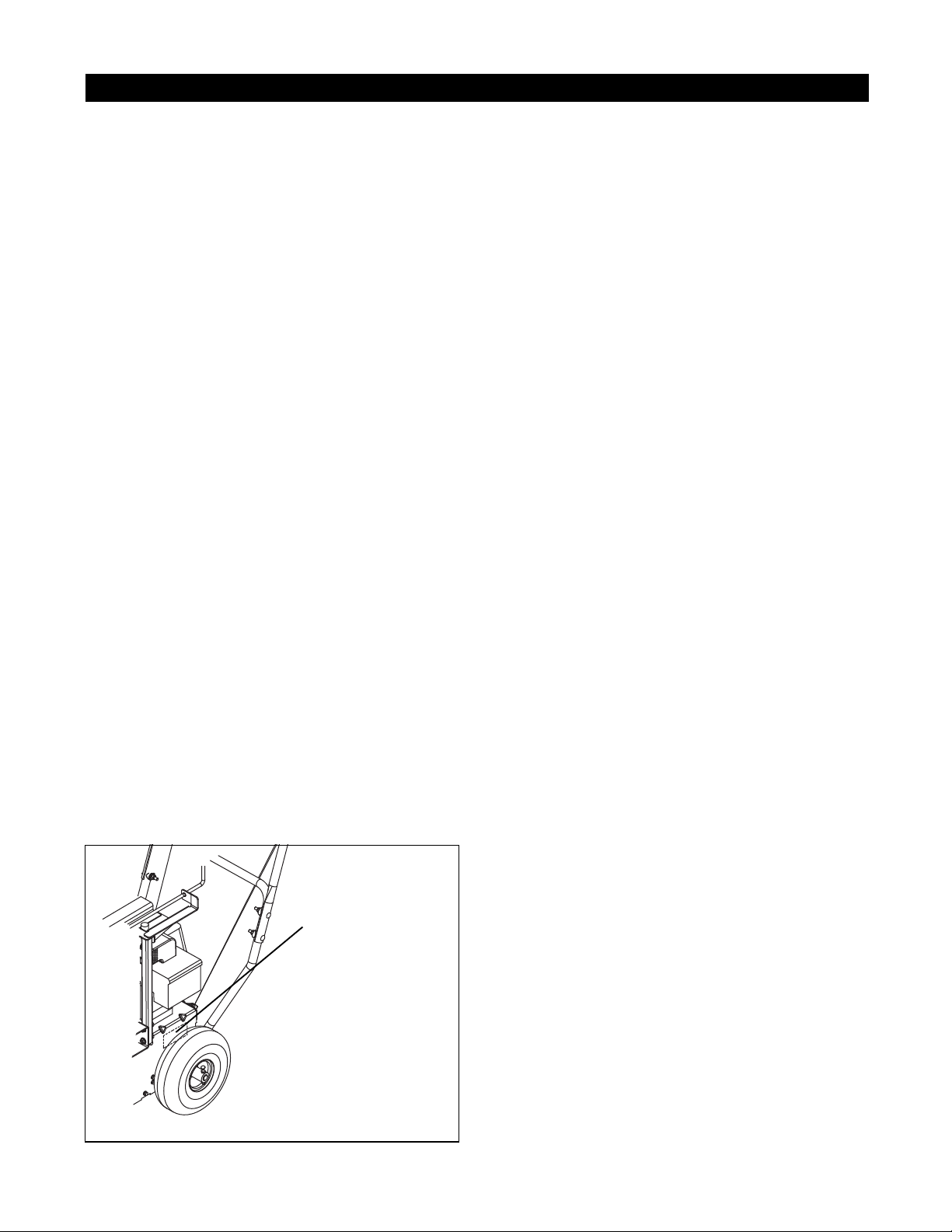
Product model and serial numbers are located on the
product registration form in the unit literature package.
They are printed on a serial number label, located on
the frame of your unit as shown in
Figure 1.
1.3 PRODUCT REGISTRATION
The Ariens dealer must register the product at the time
of purchase. Registering the product will help the
company process warranty claims or contact you with
the latest service information. All claims meeting
requirements during the limited warranty period will be
honored, whether or not the product registration card is
returned. Keep a proof of purchase if you do not
register your unit.
Customer Note: If the dealer does not register your
product, please fill out, sign, and return the product
registration card to Ariens or go to www.ariens.com.
1.4 UNAUTHORIZED REPLACEMENT PARTS
Use only Ariens replacement parts. The replacement of
any part on this vehicle with anything other than an
Ariens authorized replacement part may adversely
affect the performance, durability, or safety of this unit
and may void the warranty . Ariens disclaims liability for
any claims or damages, whether warranty, property
damage, personal injury , or death arising out of the use
of unauthorized replacement parts.
1.5 DISCLAIMER
Ariens reserves the right to discontinue, make changes
to, and add improvements upon its products at any
time without public notice or obligation. The
descriptions and specifications contained in this
manual were in effect at printing. Equipment described
within this manual may be optional. Some illustrations
may not be applicable to your unit.
1.6 TECHNICAL SERVICE COMMUNICATIONS
Ariens Technical Service communicates information to
the field using Service Letters, Service Bulletins,
Product Notices, and Campaigns. Each
communication signifies a type of information and
priority. The dealer is responsible to carry out the
directive provided in the communication. The types of
communication are:
1 - 5
Page 6
Service Letter - General technical information for the
SECTION 2 - SAFETY
Figure 2
OS7340
dealer. Technical information on how to service the
product and product improvements.
Service Bulletin - Notification to update products to
resolve certain issues or a notification of a policy
change.
Product Notices - Notification of limited product
located in a certain region. This is a limited distribution
to only those who received the product involved.
Campaigns - Notification of a safety related issue. All
product must be updated and are tracked by the
factory until all units are corrected.
2.1 SAFETY ALERTS
WARNING: To avoid injury to hands and feet,
always disengage clutches, shut off engine,
and wait for all movement to stop before
unclogging or working on snow thrower.
Hand contact with the rotating impeller is the
most common cause of injury associated with
snow throwers. Never use your hand to clean
out the discharge chute.
Keep hands and feet away from auger and
impeller.
Look for these symbols to point out
important safety precautions. They mean:
Attention!
Personal Safety Is Involved!
Become Alert!
Obey The Message!
The safety alert symbols above and signal
words below are used on decals and in this manual.
Read and understand all safety messages.
2.3 PRACTICES AND LAWS
Practice usual and customary safe working
precautions, for the benefit of yourself and others.
Understand and follow all safety messages. Be alert to
unsafe conditions and the possibility of minor,
moderate, or serious injury or death. Learn applicable
rules and laws in your area. Always follow the practices
set forth in this manual.
2.4 REQUIRED OPERATOR TRAINING
Original purchaser of this unit was instructed by the
seller on safe and proper operation. If unit is to be used
by someone other than original purchaser; loaned,
rented or sold, ALWAYS provide this manual and any
needed safety training before operation.
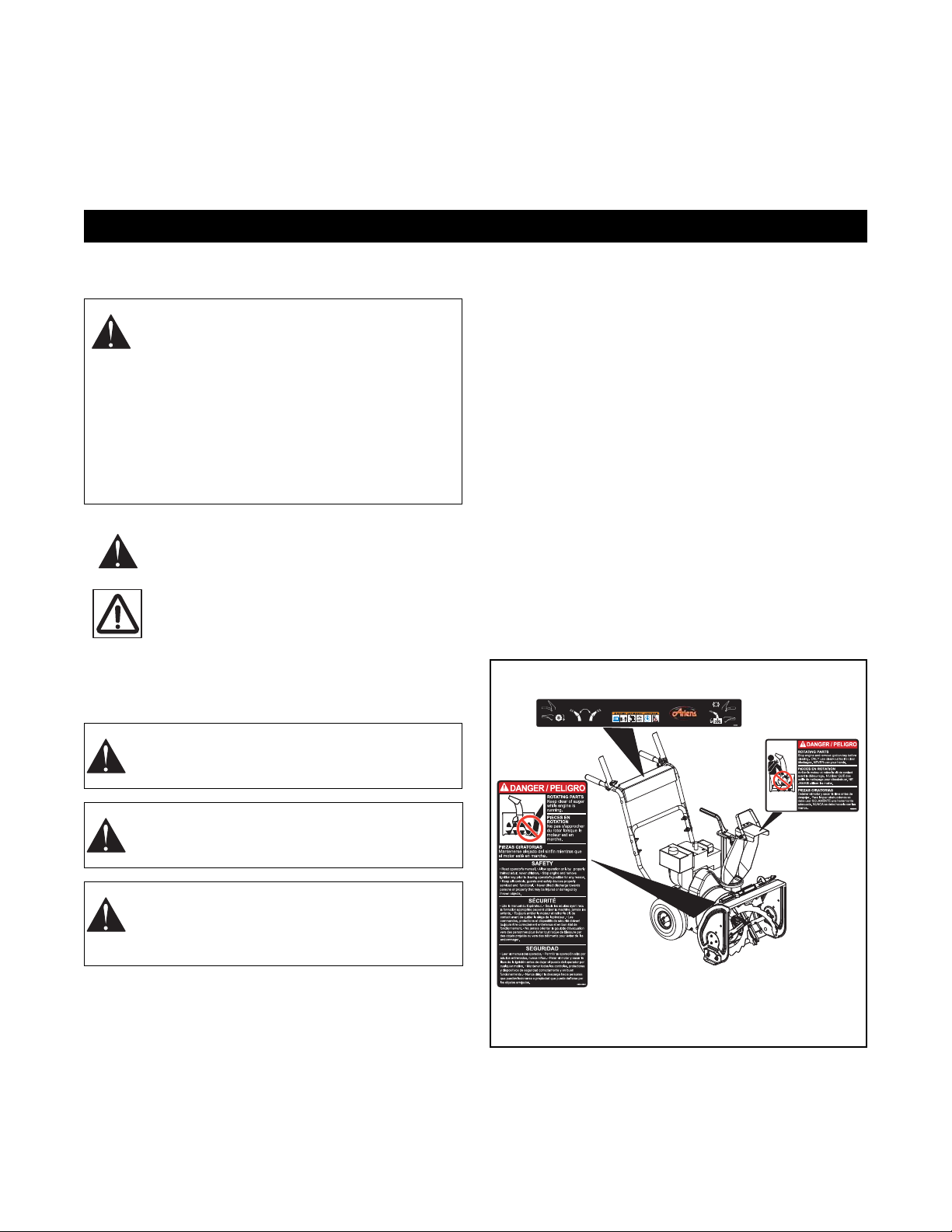
2.5 SAFETY DECALS AND LOCATIONS
ALWAYS replace missing or damaged Safety Decals.
Refer to
Figure 2 for Safety Decal locations.
DANGER: IMMINENTLY HAZARDOUS
SITUATION! If not avoided, WILL RESULT in
death or serious injury.
WARNING: POTENTIALLY HAZARDOUS
SITUATION! If not avoided, COULD RESULT in
death or serious injury.
CAUTION: POTENTIALLY HAZARDOUS
SITUATION! If not avoided, MAY RESULT in
minor or mode rate i nju ry. It may also be used to
alert against unsafe practices.
2.2 NOTATIONS
NOTE: General reference information for proper opera-
tion and maintenance practices.
IMPORTANT: Specific procedures or informati on
required to prevent damage to unit or attachment.
2 - 6
Page 7
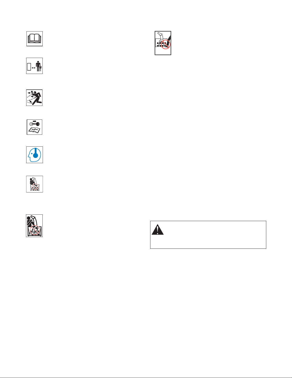
WARNING!
OL1801
OL4370
OL0910
OL4010
OL4690
OL6610
OS6610
OS2080
DANGER!
Read Owner/Operator Manual.
Keep people away from unit while
operating. Keep children out of work
area and under watchful care of a
responsible adult.
Never direct discharge towards persons
or property that may be injured or
damaged by thrown objects.
Stop engine, remove key, read manual
before making any repairs or
adjustments.
Wear appropriate hearing protection.
ONLY use clean-out tool to clear
blockages. NEVER use your hands.
2. DANGER!
ROTATING PARTS.
Keep clear of auger while engine is
running.
• Read Operator ’s Manual.
• Allow operation only by properly
trained adult, never children.
• Stop engine and remove ignition key
prior to leaving the operator’s
position for any reason.
• Keep all controls, guards and safety
devices properly serviced and
functional.
• Never direct discharge towards
persons or property that may be
injured or damaged by thrown
objects.
2.6 PREPARATION
Proper preparation is very important for efficient work
before you start to remove any parts. A clean work
area at the beginning of each job will allow you to
perform service repairs easily and quickly.
To reduce the incidence of misplaced tools or parts,
place removed components with all attaching hardware
in the disassembly order on a clean work surface.
Organization is a key part of proper reassembly.
Tools, instruments, and parts needed for the job should
be gathered before work is started. Interrupting a job to
locate tools or parts is a needless delay.
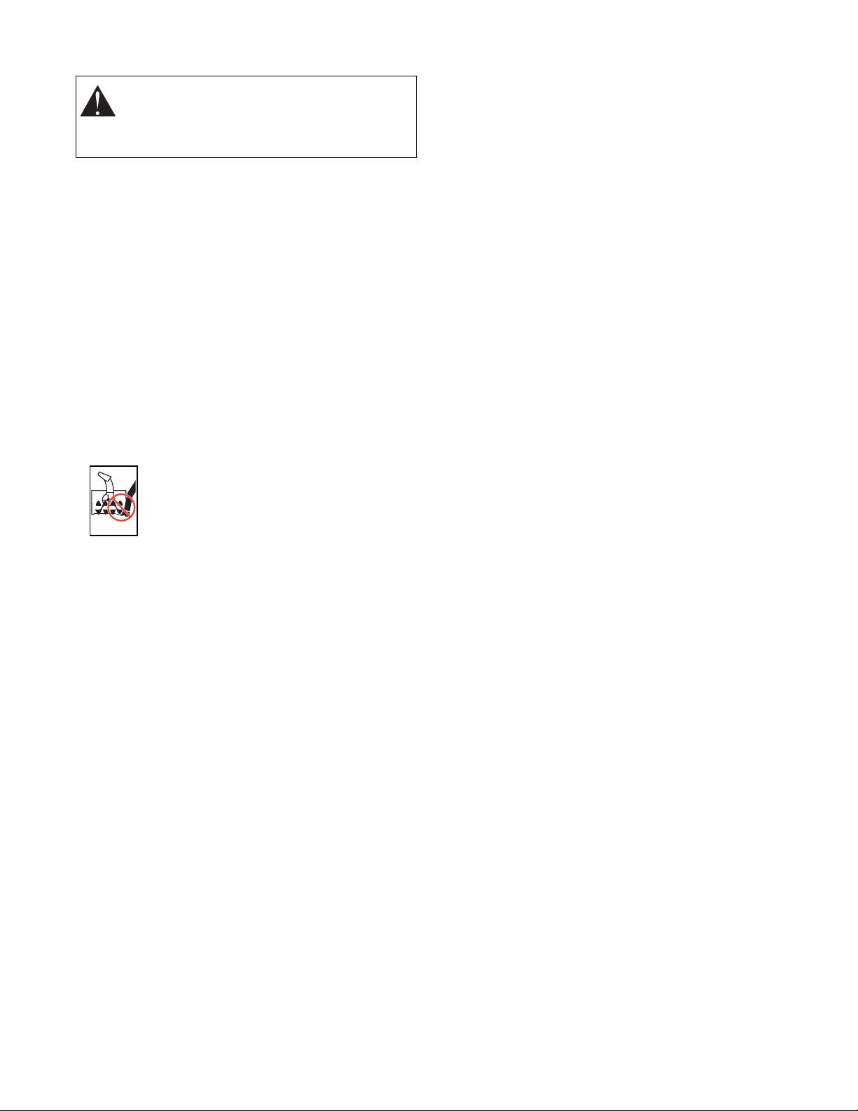
ROTATING P ARTS! ONLY use clean-out
tool to clear blockages. NEVER use your
hands. High speed impeller rotates
below discharge opening. Wait for all
moving part s to s top before re moving
clogs or servicing.
2.7 SERVICE POSITION
WARNING: ALWAYS block wheels and know
that jack stands or blocks used are stable,
strong, secure and will hold the weight of the
unit during maintenance.
To ensure the unit is positioned in the proper service
position place unit on a flat level surface. ALWAYS stop
engine. Assure unit is secure and will not tip over. Strap
and clamp onto lift if used.
See Service Position in General Maintenance for
specific instructions.
1 - 7
Page 8
2.8 CLEANING AND STORAGE
OS2080
WARNING: AVOID SHARP EDGES which
can cut. Movement of parts can cut off fingers
or a hand. Wear gloves, and use extreme
caution when servicing.
IMPORTANT: Never spray unit with water or store unit
outdoors to help prevent sealed bearing rust or
corrosion. Water can seep into sealed bearings and
reduce component life. Bearings are sealed against dirt
and debris only.
A unit that is excessively dirty should be cleaned
before work starts. Cleaning will occasionally uncover
trouble sources. Dirt and abrasive dust reduce the
efficient work life of parts and can lead to costly
replacement.
When taking unit out of extended storage:
1. Check for any damage or loose parts. Repair,
replace, or tighten hardware before operation.
2. If a preservative fluid was used in fuel tank, drain
and discard. Fill fuel tank with fresh new fuel.
ROTATING PARTS.
Keep clear of auger while engine is
running.
• Read Operator’s Manual.
• Allow operation only by properly
trained adult, never children.
• Stop engine and remove ignition key
prior to leaving the operator’s
position for any reason.
• Keep all controls, guards and safety
devices properly serviced and
functional.
• Never direct discharge towards
persons or property that may be
injured or damaged by thrown
objects.
2.9 SAFETY RULES
Read, understand, and follow all safety practices in
Owner/Operator Manual before beginning assembly or
operating. Failure to follow instructions could result in
personal injury and/or damage to unit.
ALWA YS remove key and/or wire from spark plug
before assembly, maintenance or service.
Unintentional engine start up can cause death or
serious injury.
Complete a walk around inspection of unit and work
area to understand:
• Work area • Your unit • All safety decals
ALWAYS check overhead and side clearances
carefully before operation. ALWAYS be aware of traffic
when operating along streets or curbs.
Keep children and people away. Keep children out of
work area and under watchful care of a responsible
adult.
NEVER allow children to operate or play on or near
unit. Be alert and shut off unit if children enter area.
DO NOT allow adults to operate unit without proper
training. Only trained adults may operate unit. Training
includes actual oper ati on.
Keep area of operation clear of all toys, pets, and
debris. Thrown objects can cause injury.
Check for weak spots on docks, ramps or floors. Avoid
uneven work areas and rough terrain. Stay alert for
hidden hazards.
DO NOT operate near drop-offs, ditches, or
embankments. Unit can suddenly turn over if a wheel is
over the edge of a cliff or ditch, or if an edge caves in.
Falling snow, fog, etc. can reduce vision and cause an
accident. Operate unit only when there is good visibility
and light.
NEVER operate unit after or during the use of
medication, drugs or alcohol. Safe operation requires
your complete and unimpaired attention at all times.
NEVER allow anyone to operate this unit when his or
her alertness or coordination is impaired.
DO NOT operate unit without wearing adequate winter
outer garments. Wear adequate safety gear, including
safety glasses with side shields, and protective gloves.
Wear proper footwear to improve footing on slippery
surfaces.
DO NOT wear l oose clothing or jewelry and tie back
hair that may get caught in rotating parts.
Protect eyes, face and head from objects that may be
thrown from unit. Wear appropriate hearing protection.
Avoid sharp edges. Sharp edges can cut. Moving parts
can cut off fingers or a hand.
ALWAYS keep hands and feet away from all rotating
parts during operation. Rotating parts can cut off body
parts.
NEVER place your hands or any part of your body or
clothing inside or near any moving part while unit is
running.
ALWAYS keep hands away from all pinch points.
DO NOT touch unit parts which might be hot from
operation. Allow parts to cool before attempting to
maintain, adjust or service.
Never direct discharge towards persons or property
that may be injured or damaged by thrown objects. Use
extreme caution on gravel surfaces. Stay alert for
hidden hazards or traffic. Adjust runners so scraper
blade does not contact gravel. DO NOT use on gravel
or crushed rock surfaces.
1 - 8
Page 9

DO NOT throw snow any higher than necessary.
Deflected materials can cause injury and property
damage.
Always stand clear of the discharge area when
operating this unit.
Fumes from engine exhaust can cause injury or death.
DO NOT run engine in an enclosed area. Always
provide good ventilation.
ALWAYS disengage attachment, stop unit and engine,
remove key and allow moving parts to stop before
leaving operator’s position.
ROTATING IMPELLER AUGER CAN CAUSE
SERIOUS INJURY. NEVER ATTEMPT TO UNCLOG
OR CLEAN UNIT WHILE ENGINE IS RUNNING.
Read, understand, and follow all instructions in the
manual and on the machine before starting.
Understand:
• How to operate all controls.
• The functions of all controls.
• How to STOP in an emergency.
Before starting engine, disengage control(s).
Use only approved extension cords and receptacles
when starting units equipped with electric starter. DO
NOT connect electric starter cord to any wiring system
that is not a three-wire grounded system.
ALWAYS allow unit and engine to adjust to outdoor
temperatures before clearing snow.
Always be sure of your footing, especially when
operating in reverse or leaving the operator’s position.
Walk, never run, during operation.
DO NOT overload the machine capacity by attempting
to clear snow at too fast a rate.
Slow down and turn corners slowly.
Do not operate in re vers e unl ess absol utely nece ssary.
ALW A YS back up slowly . Always look down and behind
before and while backing.
Disengage attachment drive when traveli ng from one
work area to another.
Abnormal vi brati ons ar e a warni ng of tr ouble . S t rikin g a
foreign object can damage unit. Immediately stop unit
and engine. Remove key and wait for all moving parts
to stop. Remove wire from spark plug. Inspect unit and
make any necessary repairs before restart.
Before cleaning, removing clogs or making any
inspections, repairs, etc.: disengage clutch(es), stop
unit and engine, remove key, allow moving parts to
stop. Allow hot parts to cool.
Run unit a few minutes after clearing snow to prevent
freeze-up of attachment.
Never leave a running unit unattended. Shut off engine
before leaving unit. ALWA YS remove key to prevent
unauthorized use.
Never carry passengers.
Check clutch and brake operation frequently. Adjust
and service as required. All motion of drive wheels and
auger/impeller must stop quickly when control levers
are released.
DO NOT operate on steep slopes. DO NOT clear snow
across the face of slopes. Keep all movement on
slopes slow and gradual. DO NOT make sudden
changes in speed or direction. Use a slow speed to
avoid stops or shifts on slopes. Avoid starting or
stopping on a slope.
DO NOT park unit on a slope unless absolutely
necessary. When parking on a slope always block the
wheels.
Use extra care when loading or unloading unit onto
trailer or truck.
Secure unit chassis to transport vehicle. NEVER
secure from rods or linkages that could be damaged.
DO NOT transport machine while engine is running.
Keep unit free of ice or other debris. Clean up oil or fuel
spills.
This product is equipped with an internal combustion
type engine. DO NOT use unit on or near any
unimproved, forest-covered or brush covered land
unless exhaust system is equipped with a spark
arrester meeting applicable local, state or federal laws.
A spark arrester, if it is used, must be maintained in
effective working order by operator.
Fuel is highly flammable and its vapors are explosive.
Handle with care. Use an approved fuel container.
NO smoking, NO sparks, NO flames. ALWAYS allow
engine to cool before servicing.
NEVER fill fuel tank when engine is running or hot from
operation.
NEVER fill or drain fuel tank indoors.
Replace fuel cap securely and clean up spilled fuel.
Never fill containers inside a vehicle or on a truck or
trailer bed with a plastic liner. Always place containers
on the ground away from your vehicle before filling.
When practical, remove gas-powered equipment from
the truck or trailer and refuel it on the ground. If this is
not possible, then refuel such equipment on a trailer
with a portable container, rather than from a gasoline
dispenser nozzle.
Keep the nozzle in contact with the rim of the fuel tank
or container opening at all times until fueling is
complete. Do not use a nozzle lock-open device.
If fuel is spilled on clothing, change clothing
immediately.
Before tipping unit up onto housing, remove fuel so no
spills will occur. Ensure unit is secure and will not tip
over during maintenance.
1 - 9
Page 10
ALWAYS keep protective structures, guards, and
SECTION 3 - SPECIFICATIONS
panels in good repair, in place and securely fastened.
NEVER modify or remove safety devices.
DO NOT change engine governor settings or overspeed engine.
Fumes from engine exhaust can cause injury or death.
DO NOT run engine in an enclosed area. Always
provide good ventilation.
ALWAYS maintain unit in safe operating condition.
Damaged or worn out muffler can cause fire or
explosion.
Keep all hardware properly tightened. Check shear
bolts frequently. Check slip clutch on units so
equipped.
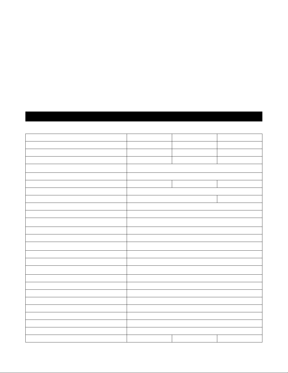
Model Number 939001 939002 939300
Description ST520E ST520 ST520
Engine - Tecumseh LH195SA LH195SA OH195SA
Engine Power – hp (kW) at Maximum RPM 5.0 (3.7) 5.0 (3.7) 5.9 (3.7)
Fast Idle Speed-RPM (min-1)
Displacement - in. (cc) 11.88 (195)
Electric Start 120V Recoil Recoil
Fuel See Engine Manual
Tank Capacity - qt. (L) 2.0 (1.96) 3.0 (2.8)
Snow Clearing Width - in. (cm) 20 (50.8)
Chute
Rotation Angle
Impeller
Diameter - in. (cm) 12 (30.5)
Speed-RPM-Max (min-1)
Auger
Diameter - in. (cm) 11.0 (27.98)
Speed-RPM-Max (min-1)
Auger Brake Yes
Drive Clutching Wet Sump Gearbox
Speeds 1 Forward
Pneumatic Tires - in. 10
Size and Weight
Height - in. (cm) 43.13 (109.53)
Length - in. (cm) 51.25 (130.18)
Width - in. (cm) 22.38 (56.84)
Weight - lb (Kg) 125 (56.7) 120 (54.4) 121 (54.8)
Maintain or replace safety and instruction labels, as
necessary.
NEVER store unit with fuel in fuel tank, inside a
building where any ignition sources are present such
as hot water heaters, space heaters, or clothes dryers.
Allow the engine to cool before storing in any
enclosure.
For extended storage, clean unit thoroughly. See
Engine Manual for proper storage.
Use only attachments or accessories designed for your
unit.
Check components frequently. If worn or damaged,
replace with manufacturer’s recommended parts.
3600 ± 150
200°
1200
120
3 - 10
Page 11
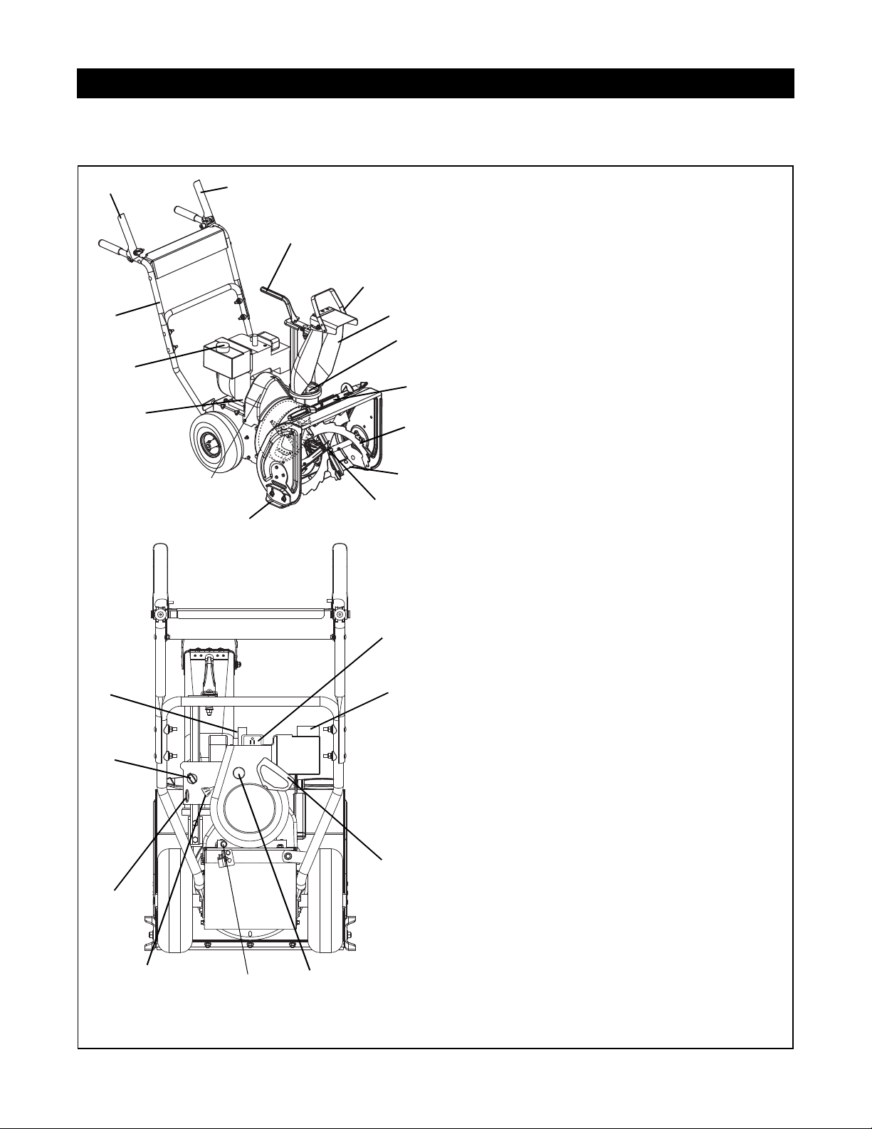
4.1 CONTROLS AND FEATURES
SECTION 4 - GENERAL MAINTENANCE & ADJUSTMENTS
3
17
14
1
11
7
21
18
12
9
4
5
10
19
2
15
23
6
12
13
20
22
16
1. Attachment Clutch Lever
2. Traction Drive Clutch Lever
3. Chute Handle (939001, 002)
4. Discharge Chute Deflector
5. Discharge Chute
6. Impeller
7. Clean-Out Tool
8. Auger
9. Scraper Blade
10.Auger Gear Case
11. Oil Fill and Dipstick
12.Gas Tank and Cap
13.Electric Starter (93900 1)
14.Recoil Starter Handle
15.Primer Bulb
16.Oil Drain Plug
17.Throttle (Engine Stop)
18.Ignition Switch (push-pull)
19.Choke
20.Spark Plug and Wire
21.Runner(s)
22.Belt Cover
23.Handlebar
OS7350
Figure 3
8
OS7355
4 - 11
Page 12
Ariens dealers provide any service or adjustments
Service Position
OS7125
Figure 4
required to keep your unit operating at peak efficiency.
Should engine service be required, contact an Ariens
dealer or an authorized engine manufacturer's service
center.
WARNING: AVOID INJURY. Read and
understand the entire Safety section before
proceeding.
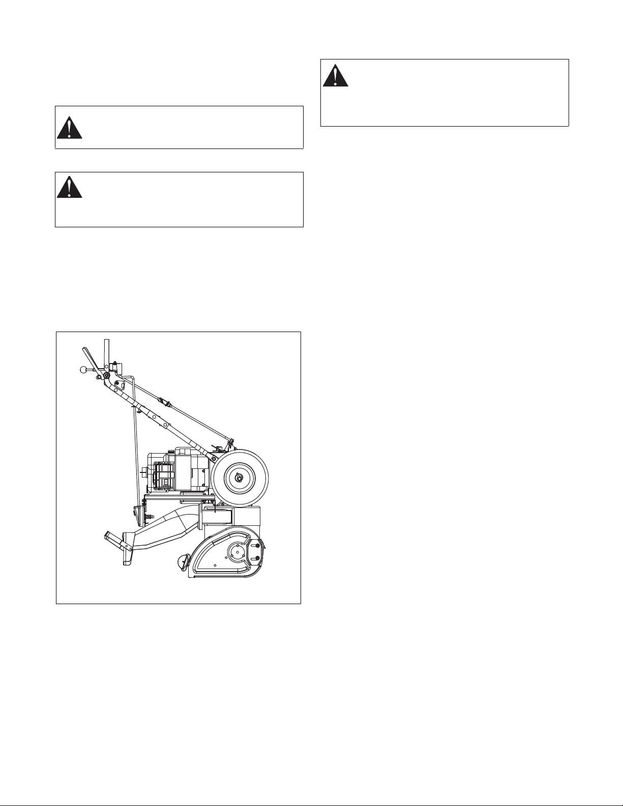
4.2 SERVICE POSITION
WARNING: Before tipping unit up onto housing,
remove fuel so no spills will occur and remove
battery (if equipped). Ensure unit is secure and
will not tip over during maintenance.
Place unit on a flat level surface. Tip machine forward
onto front of impeller housing for service as shown in
Figure 4. Assure unit is secure and will not tip over.
Strap and clamp onto bench if needed.
NOTE: Machine should remain in horizontal position to
service attachment and drive belts. Do not tip machine
forward.
4.4 STARTING AND SHUTTING OFF
WARNING: FAILURE TO FOLLOW
INSTRUCTIONS could result in personal injury
and/or damage to unit. DO NOT attempt to start
your unit at this time. Read entire Owner/
Operator Manual and the Engine Manual first.
IMPORTANT: Allow unit and engine to adjust to
outdoor temperatures before clearing snow. Before
shut-off, run the attachment a few minutes to prevent
freeze-up.
IMPORTANT: Try each control without the engine
running to see how it works and what it does.
Manual Start
1. Turn discharge chute straight ahead.
2. Make sure that the traction clutch and attachment
drive clutch levers are fully disengaged.
3. Push primer bulb 2 or 3 times for cold engine.
NOTE: When temperature is below -15° F (-26° C)
additional priming may be needed.
4. If engine is cold, apply choke. See Engine Manual
for detailed instructions.
NOTE: A warm engine requires less choking than a
cold engine.
5. Set throttle to proper starting position.
6. Insert key into ignition switch and push into RUN
position. DO NOT twist key after it is inserted.
7. Grasp starter handle and pull rope out slowly until it
pulls harder. Let rope rewind slowly.
8. Pull rope with a rapid continuous full arm stroke.
Let rope rewind slowly.
IMPORTANT: DO NOT let starter handle snap against
starter.
9. Repeat steps 7 and 8 until engine starts. (If engine
does not start, refer to Troubleshooting.)
10.Adjust choke as needed.
1 1.Set throttle to PART THROTTLE or SLOW position
for adaptation to outside temperature or travel. Set
throttle to FAST position for normal operation.
4.3 STOPPING IN AN EMERGENCY
Immediately release both control levers to stop unit in
an emergency. Stop engine, remove key and wait for
all rotating parts to stop before leaving operator’s
position.
Electric Start
1. Connect extension cord to prongs on starter.
IMPORTANT: Prevent damage to unit. Know voltage of
your starter and use only matching outlets.
2. Plug extension cord into 120V or 240V 3-wire,
grounded outlet.
3. Turn discharge chute straight ahead.
4. Make sure that the traction clutch and attachment
drive clutch levers are fully disengaged.
5. Push primer bulb 2 or 3 times for cold engine.
NOTE: When temperature is below -15° F (-26° C)
additional priming may be needed.
4 - 12
Page 13
6. Insert key into ignition switch on engine and push
into RUN position. DO NOT twist key after it is
inserted.
7. If engine is cold, apply choke. A warm engine
requires less choking than a cold engine. See
Engine Manual for detailed instructions.
8. Set throttle to proper starting position.
9. Press starter button on engine until engine starts.
IMPORTANT: DO NOT operate starter more than 15
seconds per minute, as overheating and damage can
occur. (If engine does not start, refer to
Troubleshooting.)
10.Adjust choke as needed.
11.Disconnect extension cord from outlet first, then
starter.
12.Set throttle to PART THROTTLE or SLOW position
for travel or adaptation to outside temperature.
Once achieved, set throttle to FAST position for
normal operation.
Shut Off
1. Release traction drive clutch lever and allow unit to
come to a complete stop.
2. Run Impeller a few minutes after use to keep
impeller from freezing up.
3. Release attachment clutch lever and wait for all
moving parts to come to a complete stop.
4. Move throttle to STOP position.
5. Remove key.
7. ALWAYS clean up any spilled fuel.
WARNING: POTENTIAL HAZARD! Fuel is
extremely flammable and highly explosive.
Personal injury and property damage may
result if not handled properly.
• Fill the fuel tank outdoors in an open area.
• Do not fill when the engine is hot. Wipe up
any fuel spills.
• Never fill the fuel tank completely full.
Empty space in tank allows fuel to
expand.
• Never smoke when handling fuel. Stay
away from open flames. Fuel fumes can
be ignited by sparks.
4.6 PRE-START
Frozen Impeller
IMPORTANT: Before starting engine, check impeller to
be sure it is not frozen.
To check impeller:
1. With key in STOP position, squeeze attachment
clutch lever to engaged position.
2. Pull recoil starter handle. If you cannot pull handle,
impeller is frozen.
3. If impeller is frozen, move unit to a heated area
and thaw to prevent possible damage.
4.5 FUEL TANK
To add fuel to the fuel tank:
1. ALW AYS place unit in open or well- ventilated area.
2. Stop engine and allow to cool.
3. Clean fuel cap and surrounding area to prevent dirt
from entering fuel tank.
4. Remove cap.
IMPORTANT: DO NOT use gasohol or gasoline
containing alcohol. See Engine Manual for correct type
and grade of fuel.
5. Fill fuel tank to within 1/2 in. (1.2 cm) below bottom
of filler neck with unleaded gasoline.
NOTE: Tank capacity is 2.0 (1.96) for 939001 or
939002, 3.0 (2.8) for 939300.
6. Replace fuel cap and tighten.
4 - 13
Page 14
4.7 MAINTENANCE SCHEDULE
1.Auger Gear Case
2. Filler Plug
3. Auger Shaft
1
2
OS1870
Figure 5
3
3
The chart below shows the recommended
maintenance schedule that should be performed on a
regular basis. More frequent service may be required.
Service Performed Each
Use
Check Fasteners
Check Clutch
Operation
Every 5 hrEvery
•
•
Yearly
25 hr
Check Clutch
Spring
* •
Adjustments
Clean Engine
Check Engine Oil
Change Engine
Oil
Check Tire
Pressure
Check Auger
Gear Case
General
Lubrication
•
•
** •
•
• •
• •
* After first five hours of operation.
** After first two hours of operation.
Check Fasteners
Make sure all hardware is tightened properly.
Change Engine Oil
Change oil after first 2 hours of operation; thereafter,
change oil every 25 hours (more often if required).
Refer to Engine Manual for detailed instructions.
Run engine a few minutes just before changing oil.
Warm oil will flow more freely and carry away more
contamination. Place a suitable container under the oil
drain plug. Remove the oil drain plug from the rear of
the unit and tip the unit back to help drain all the oil.
Check Tire Pressure
Keep tires at pressure listed on the tire sidewall.
Check Auger Gear Case
IMPORTANT: Proper oil level must be maintained.
Gear cases are filled to the correct level at the factory.
Unless there is evidence of leakage, no additional
lubricant should be required. Check oil level each
season or every 25 hours of operation.
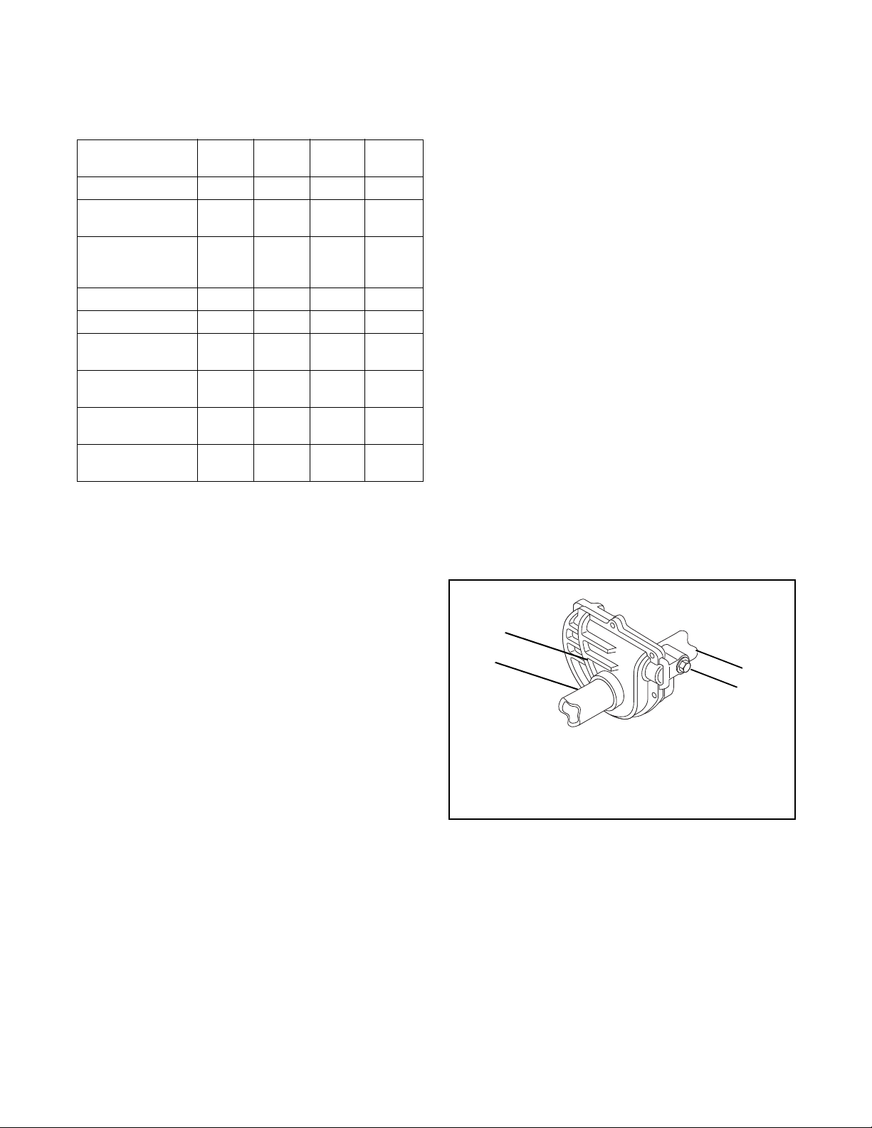
To ensure adequate lubricant level:
1. Remove filler plug (Figure 5). Lubricant must be at
least up to bottom of lubricant filler hole with unit
resting on a level-surface.
2. Add lubricant if required. Allow oil to drain to level
of plug and replace plug.
IMPORTANT: Use only Ariens special gear lubricant
L-2 (Part Number 00008000). Gear case filler plug may
require an application of Loc-Tite® 565 thread sealant
with repeated servicing.
Check Clutch Operation
Auger and impeller must stop within 3 seconds when
attachment clutch/impeller brake lever is released.
Wheels must stop quickly when traction drive clutch
lever is released.
If clutches do not engage or disengage properly, adjust
or repair before operation (see
“Attachment Clutch/
Brake Adjustment” on page 18 or “Traction Drive
Clutch Adjustment” on page 19).
Check Clutch Spring Adjustment
Make sure the attachment clutch and traction drive
clutch are adjusted to the range specified in
“Attachment Clutch/Brake Adjustment” on page 18 or
“Traction Drive Clutch Adjustment” on page 19
Clean Engine
Refer to Engine Manual for detailed instructions.
Check Engine Oil
Check engine crankcase oil every 5 hours of operation.
Oil level MUST be maintained in safe operating range
on dipstick at all times or engine damage will result
(See Engine Manual).
Park unit on a level surface. Refer to Engine Manual for
detailed instructions.
General Lubrication
IMPORTANT: Wipe each fitting clean before and after
lubrication. Do not wipe gear case filler plug; wiping the
gear case filler plug may remove thread sealant and
cause leaks.
IMPORTANT: DO NOT allow grease or oil to get on the
belts.
NOTE: Apply Ariens Hi-Temp Grease or equivalent to
the lubrication fittings. See
“Service Parts List” on
page 32.
Lubricate Sno-Thro at the beginning of the season or
every 25 operating hours, whichever comes first.
4 - 14
Page 15
Auger Shaft
OS1374
Grease
Oil
Figure 6
Figure 7
1.Blower Housing
2. Belt Cover
3. Frame
4. Belt Cover Screw
5. Housing Bolt Holes
OS7400
1
2
3
4
5
Figure 8
1.Attachment Drive Belt
2. Engine Sheave
3. Traction Drive Belt
4. Attachment Idler Nut
5. Attachment Belt Idler
6. Belt Finger
1
2
3
4
5
6
6
OS7410
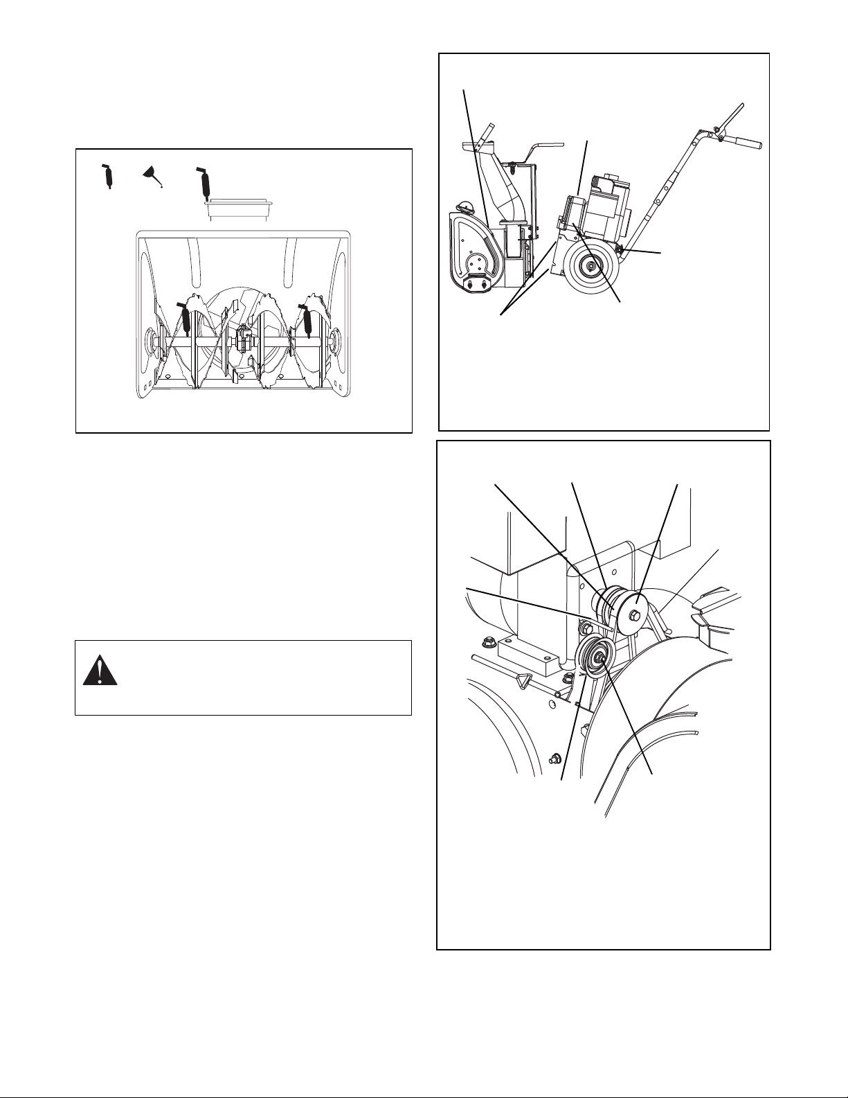
To grease auger shaft, remove shear bolt nuts and
shear bolts. Appl y grea se at the gr ease zerks and t hen
rotate the auger shaft. Replace shear bolts per
instructions in
“Shear Bolts” on page 17.
4.8 ATTACHMENT DRIVE BELT REPLACEMENT
Remove Attachment Drive Belt
(Figures 7 and 8)
1. Shut off engine, remove key, disconnect spark plug
2. Remove two screws securing belt cover to unit and
3. Remove belt fingers by removing cap screws
IMPORTANT: To avoid bending bottom cover, remove
the cover before separating the blower housing from
the unit.
4. Support Sno-Thro frame and housing.
5. Remove top two cap screws and loosen lower two
6. Remove attachment drive belt from engine sheave
7. Separate housing from unit. Lower handlebar to
8. Remove attachment drive belt from lower pulley.
wire and allow unit to cool completely.
remove belt cover.
mounting belt fingers to engine (
Figure 8).
CAUTION: Always support Sno-Thro frame
and housing when loosening the cap screws
holding them together. Never loosen cap
screws while unit is in service position.
cap screws holding blower housing to frame (one
on each side).
(it may be necessary to turn engine sheave using
recoil starter handle).
floor.
4 - 15
Page 16
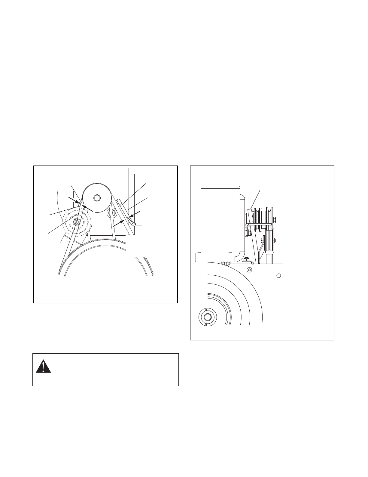
Replace Attachment Drive Belt
1/8–3/16 in.
(3.2–4.8 mm)
1.Belt Finger
2. Belt
1
2
2
1
1/8–3/16 in.
(3.2–4.8 mm)
Figure 9
OS7415
Position the traction drive
belt on the engine
sheave like this when
removing and installing it.
Figure 10
OS7420
1. Place new belt onto lower pulley.
2. While holding brake out of way, tip unit together.
NOTE: Engage attachment clutch lever while connecting housing to frame to hold brake out of the way.
3. Attach blower housing to frame with cap screws
removed in step
Belt” on page 15.
4. Place belt onto engine sheave.
5. Replace belt fingers.
IMPORTANT: BELT FINGERS MUST BE SET as
shown in
Figure 9. Improper adjustment may cause
impeller to rotate while attachment clutch is
disengaged.
6. Adjust clutch per instructions under “Attachment
Clutch/Brake Adjustment” on page 18.
7. Replace belt cover and secure with cap screws.
5 of “Remove Attachment Drive
NOTE: To make belt removal easier, slowly pull the
recoil starter while pushing the traction drive belt off the
engine pulley.
4. Remove traction drive belt from the unit and discard.
5. Place new traction drive belt on engine pulley between the engine and pulley groove as shown in Figure 10.
6. Place new traction drive belt on transmission pulley
7. Push the new traction drive belt onto the grooves in the engine pulley.
NOTE: Slowly pull the recoil starter while pushing the
traction drive belt onto the engine pulley. Make sure the
belt seats properly in the grooves of the transmission
and engine pulleys.
8. Replace attachment drive belt (See “Traction Drive Belt Replacement” on page 16).
9. Check traction drive clutch adjustment. See “Traction Drive Clutch Adjustment” on page 19.
4.9 TRACTION DRIVE BELT REPLACEMENT
NOTE: Housing and frame must be tipped apart and
attachment drive belt removed from engine sheave in
order to change traction drive belt (Figure
CAUTION: Always support Sno-Thro frame
and blower housing when loosening the cap
screws holding them together. Never loosen
7).
cap screws while unit is in service position.
1. Shut off engine, remove key, disconnect spark plug wire and allow unit to cool completely.
2. Remove attachment drive belt (See “Remove Attachment Drive Belt” on page 15).
3. Push the traction drive belt off the engine pulley
toward the engine as shown in
Figure 10.
4 - 16
Page 17
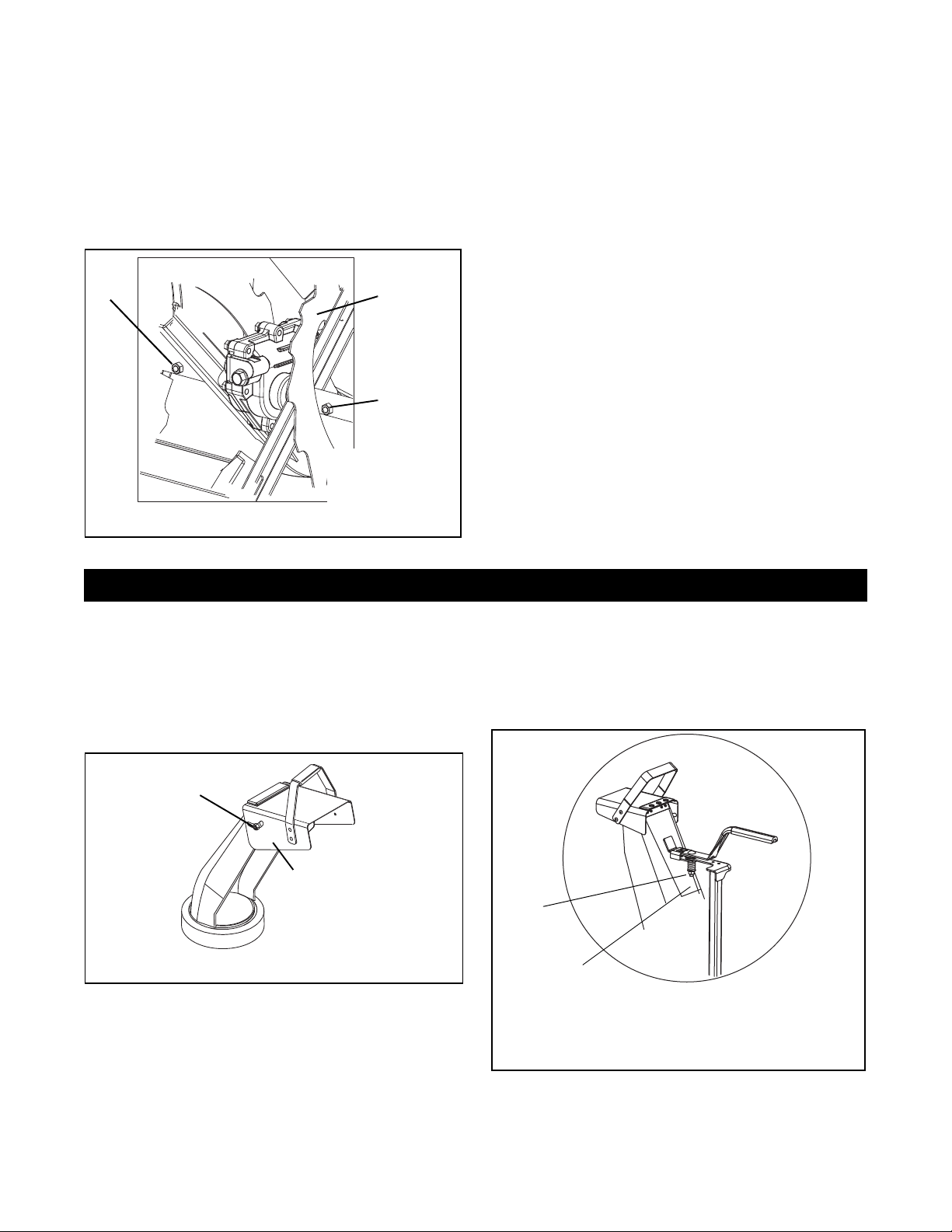
4.10 SHEAR BOLTS
1
2
2
1.Auger
2. Shear Bolts
Figure 11
OS7370
SECTION 5 - SERVICE AND ADJUSTMENTS
Adjusting
Hardware
OS1113
Discharge
Chute Deflector
Figure 12
1.Carriage Bolt
2. Spring
1
2
Figure 13
OS7375
IMPORTANT: Use only Ariens shear bolts for
replacement. Use of any other type of shear bolt may
result in severe damage to unit.
Occasionally a foreign object entering the blower
housing may jam the auger and break the shear bolts
(
Figure 11) that secure the auger to the shaft. Breaking
the shear bolts prevents damage to the gear drive by
allowing the auger to turn freely on the shaft.
Shear Bolt Replacement
1. Align shear bolt holes in auger with shear bolt holes in shaft.
2. Drive shear bolt through hole. (If shear bolt was broken, this will drive remaining part from shaft.)
3. Secure shear bolt with nut.
NOTE: DO NOT overtighten the shear bolt. Tighten
shear bolt to 5.8
– 12.2 lbf-ft (7.9 – 16.5 N•m).
4.11 TIRE PRESSURE
Keep tires inflated to pressure listed on the tire
sidewall.
5.1 DISCHARGE CHUTE DEFLECTOR
The deflector must stay in selected position while
throwing snow.
To adjust, loosen then retighten hardware to desired
deflector drag force (
Figure 12).
5.2 DISCHARGE CHUTE
If chute does not stay in position while operating,
tighten nut on carriage bolt at pivot point to increase
tension on spring (
Figure 13).
5 - 17
Page 18
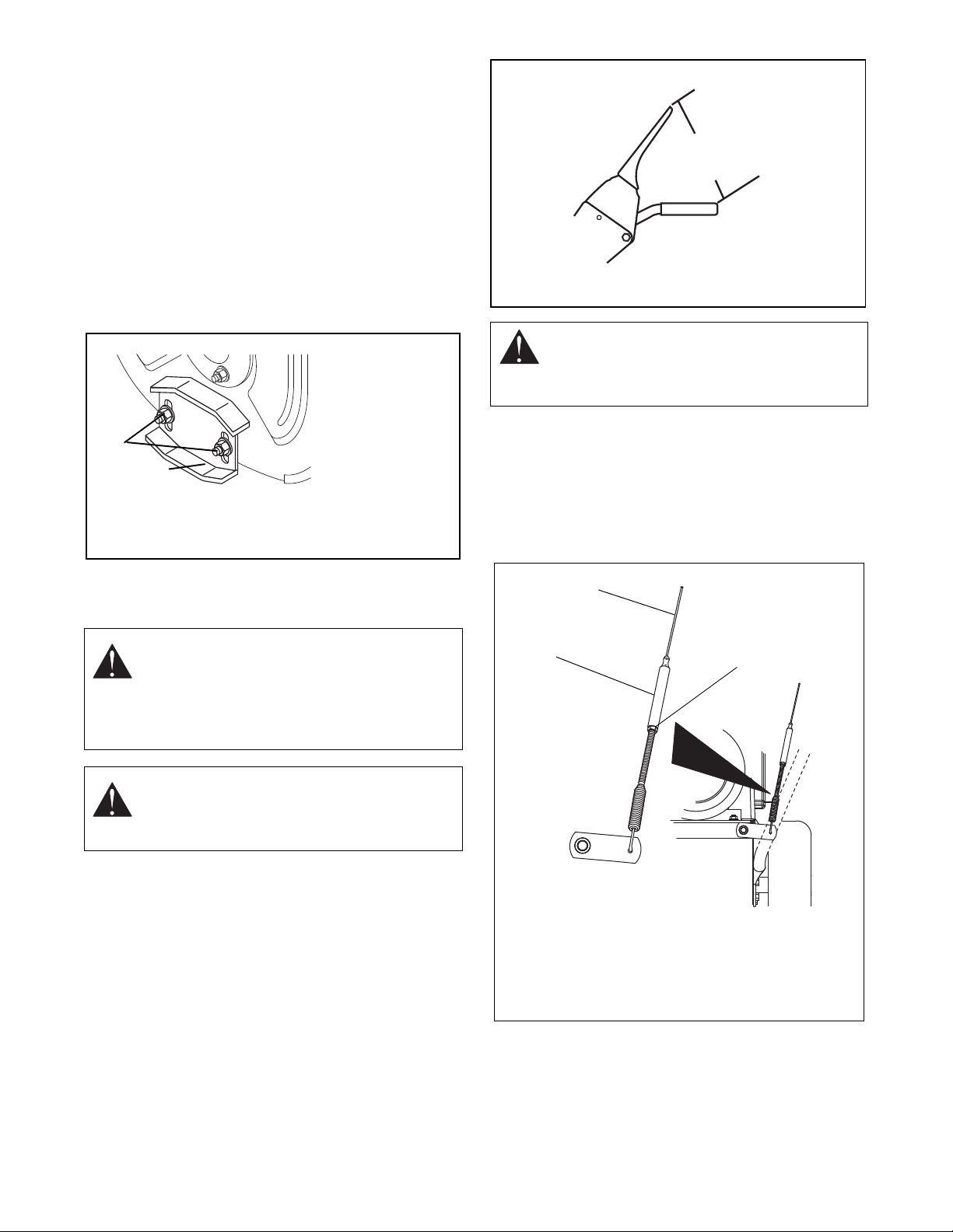
5.3 RUNNERS
2
1
OS0482
1.Runner
2. Runner Hardware
Figure 14
Attachment Clutch Lever
OS0458
(14,3 cm - 15,9 cm)
5-5/8 - 6-1/4 in.
Figure 15
Figure 16
3. Attachment Clutch
Cable
4. Jam N ut
5. Adjustment Barrel
2
1
3
OS7385
Runners should be adjusted as co nditio ns requi re
(
Figure 14).
1. Position unit on a hard, flat, smooth level surface.
2. Adjust runners by inserting a spacer of desired
thickness under center of scraper blade, loosen
runner hardware, slide runners to flat surface.
Allow 1/8
hard smooth surfaces. Allow 1-1/4
between scraper blade and uneven or gravel
surfaces. Retighten hardware.
NOTE: Keep housing level by adjusting runners
equally.
in. (3 mm) between scraper blade and
in. (30 mm)
CAUTION: The at tac hment clut ch cabl e must
be slightly slack when the clutch lever is
disengaged. The attachment brake will not
function properly if the cable is too taut.
2. Loosen jam nut on attachment clutch cable
adjustm ent barrel (
Figure 16).
Turn adjustment barrel up the cable to decrease
the distance between clutch lever and handlebar.
Turn the adjustment barrel down the cable to
increase the distance between clutch lever and
handlebar.
5.4 ATTACHMENT CLUTCH/BRAKE ADJUSTMENT
WARNING: IMPROPER ADJUSTMENT
could result in unexpected movement of
auger and impeller, causing death or serious
injury. AUGER / IMPELLER MUST STOP
within 3 seconds when Attachment Clutch/
Impeller Brake Lever is released.
1. Check attachment clutch lever measur eme nt:
WARNING: Adjustment procedure requires
running engine with the belt cover off. AVOID
INJURY. Read and understand the entire
Safety section before proceeding.
a. Start engine and run at full throttle.
b. Slowly squeeze the attachment clutch lever
until auger shaft begins to rotate.
c. Measure the distance from the end of clutch
lever to the handlebar as shown in
The distance between the end of the clutch
lever and the handlebar should be 5-5/8 - 6-1/4
in. (14.3 - 15.9 cm).
d. Shut off engine.
e. If clutch lever measurement is within specified
range, no adjustment is necessary. If clutch
lever measurement is outside the specified
range, follow steps 2 - 7.
Figure 15.
3. Check attachment clutch lever measurement and
tighten the jam nut on the attachment clutch cable
adjustment barrel when the clutch lever
measurement is in range. Proceed to step
If clutch cannot be adjusted to specified range with
the cable adjustment alone, perform steps
5 - 18
6.
4 – 5.
Page 19
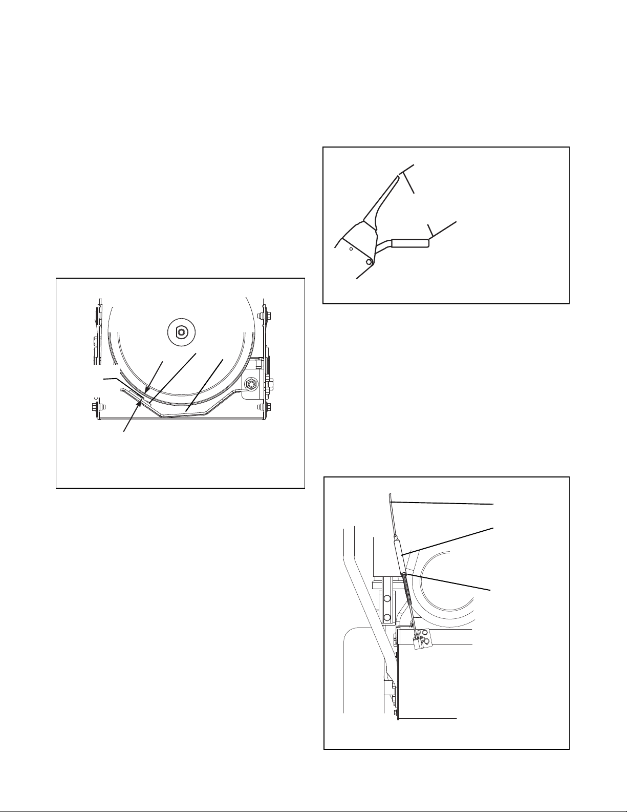
4. Remove two screws securing belt cover to unit and
Figure 17
1.Drive Brake
2. Brake Shoe and Pad
1
2
1/16 in.
(1,6 mm)
OS7390
OS2490
Figure 18
Traction Clutch Lever
6-1/8 – 6-3/4 in.
(15.5 – 17.1 cm)
Figure 19
1.Traction Clutch
Cable
2. Jam Nut
3. Adjustment Barrel
1
3
2
OS7395
remove belt cover.
5. Adjust the attachment idler position.
a. Loosen attachment idler nut (Figure 8).
b. To increase distance betw een clutch lever
and handlebar, move the idler towards the
attachment belt.
c. To decrease the distance between the clutch
lever and handlebar, move the idler away
from the attachment belt.
d. Tighten idler adjustment nut.
e. Check clutch lever measurement.
6. Check Brake
When the clutch lever is disengaged, the brake
must contact the attachment belt.
When the clutch lever is engaged, the brake must
be more than 1/16 in. (1.6
belt and must not contact the frame (
mm) away from the
Figure 17).
To test traction clutch (Figure 18):
1. Without engine running, push unit forward while
slowly moving the traction drive clutch lever toward
the handlebar.
2. Measure distance between lever and handlebar
when the wheels begin to brake. If distance is not
6-1/8 – 6-3/4 in. (15.5 – 17.1
cm), adjust the
traction clutch.
To adjust traction clutch (Figure 19):
1. Loosen jam nut on traction clutch cable adjustment
barrel.
Turn adjustment barrel up the cable to decrease
the distance between clutch lever and handlebar.
Turn the adjustment barrel down the cable to
increase the distance between clutch lever and
handlebar.
2. Check traction clutch lever distance and repeat
adjustment steps if necessary.
3. Tighten jam nut on traction cable adjustment
barrel.
7. Repeat steps 5 – 6 until attachment clutch lever
distance and brake contact are correct.
IMPORTANT: If attachment clutch/brake cannot be
adjusted within tolerances, see your Dealer for repairs.
8. Check belt finger clearance.
With clutch lever engaged, belt fingers should be
positioned as shown in
fingers as necessary.
Figure 9. Adjust belt
9. Replace belt cover.
10.Check that auger/impeller stops within 3 seconds
after attachment clutch/impeller brake lever is
released.
5.5 TRACTION DRIVE CLUTCH ADJUSTMENT
IMPORTANT: Operating the unit with the traction drive
clutch improperly adjusted will damage the
transmission. Make sure the clutch is adjusted to the
specifications listed.
5 - 19
Page 20
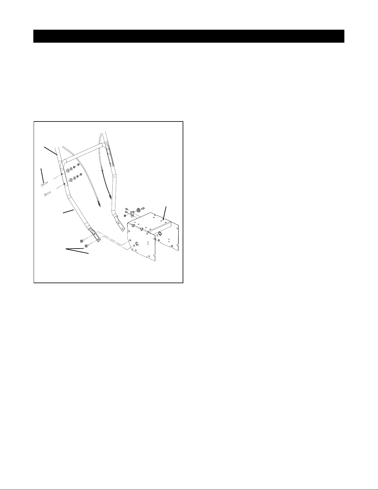
6.1 INSPECT LOWER HANDLEBAR
SECTION 6 - HANDLEBARS & CONTROLS
Figure 20
4
5
3
1
2
1.Upper Handlebars
2. Bolt w/Nut, Spacer
and Washers
3. Lower Handlebars
4. Bolts
5. Frame
PS0350-1
1. Remove bolts attaching lower handlebar to each
side of frame (2 places, each side) (see
2. Remove handlebar assemb ly.
3. Check lower handlebar parts for wear or
replacement
4. Assemble, using reverse procedure.
Figure 20).
6.3 TRACTION DRIVE CLUTCH LEVER AND CABLE
Clutch Lever
Figure 21
1. Remove jam nut and flat washer from bolt.
2. Remove bushings and torsion spring.
3. Remove retaining ring and traction cable
4. Remove clutch lever.
5. Check parts for wear or replacement.
6. Assemble, using reverse procedure. Attach cable
to bolt during assembly.
7. Adjust clutch lever position if necessary (see
“Traction Drive Clutch Adjustment” on page 19).
Traction Drive
Figure 21
1. Remove clutch lever from upper handlebar (See
preceding
2. Slide cable off bolt.
3. Disconnect cable spring from control under frame.
4. Check cable for wear. Replace if necessary
5. Assemble, using reverse procedure.
NOTE: BE sure to route cable over small pulley
mounted to frame
6. Adjust clutch lever position if necessary (see
“Traction Drive Clutch Adjustment” on page 19).
Clutch Lever for procedure.)
6.2 REPLACE LOWER HANDLEBAR
Figure 20
1. Remove locking nuts, lock washers, washers, and
spacers from bolt attaching upper handlebars to
lower handlebars (2 places, each side).
2. Lay upper handlebars and control panel on bench
or ground.
NOTE: Removing control cables is not necessary to
replace lower handlebar s.
3. Remove bolts attaching lower handlebar to each
side of frame (2 places, each side).
4. Remove lower handlebar.
5. Install new lower handlebar using reverse
procedure.
6. Attach upper handlebars to lower handlebars.
6 - 20
Page 21
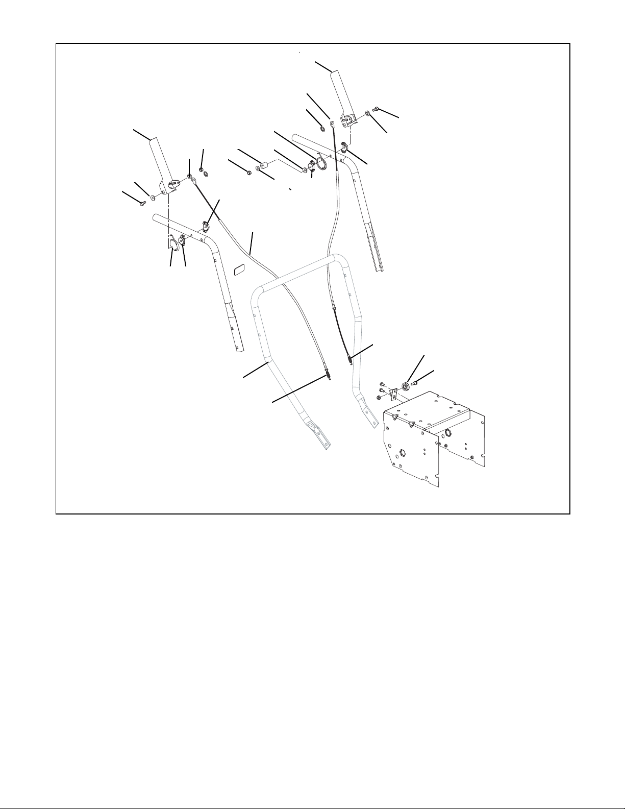
Figure 21
1
2
4
2
3
4
6
5
2
8
9
10
11
12
2
7
13
7
78
14
14
15
16
17
7
1.Bolt (2-1/2")
2. Flange Bushing
3. Clutch Lever (Right Hand)
4. Jam Nut
5. Flat Washer
6. Sleeve Bushing
7. Bushing
8. Torsion Spring
9. Retaining Ring
10.Tractio n Cable
11. Clutch Lever (left Hand)
12.Bolt (3-1/4")
13.Attachment Cable
14.Spring
15.Pulley
16.Bolt w/nut
17.Lower Handle
PS0350-2
6.4 ATTACHMENT CONTROL LEVER AND CABLE
Attachment Lever
Figure 21
1. Remove jam nut and flat washer from bolt.
2. Remove bushings and torsion spring.
3. Remove retaining ring and traction cable
4. Remove clutch lever.
5. Assemble, using reverse procedure. Attach cable
to bolt during assembly.
6. Adjust clutch lever position if necessary (see
“Attachment Clutch/Brake Adjustment” on
page 18).
Attachment Cable
Figure 21
1. Remove clutch lever from upper handlebars (See
preceding
2. Slide cable off bolt.
3. Disconnect cable spring from control under frame.
4. Check parts for wear or replacement.
5. Assemble, using reverse procedure.
6. Adjust clutch lever position if necessary
(see
page 18).
6 - 21
Attachment Lever for procedure.)
“Attachment Clutch/Brake Adjustment” on
Page 22

7.1 ENGINE TROUBLESHOOTING
SECTION 7 - ENGINE
The following troubleshooting chart is to be used to
isolate engine problems and give possible causes and
corrective action responses.
ENGINE TROUBLESHOOTING
PROBLEM PROBABLE CAUSE CORRECTION
Black Exhaust Restriction in air cleaner Remove obstruction
Poor compression Repair per ins tructions in manufacturer’s manual
Incorrect grade of fuel Use fuel recommended in manufacturer’s manual
Leaking cylinder head gasket Replace per instructions in manufacturer’s manual
Sticking valves Repair per ins tructions in manufacturer’s manual
Worn cylinder bores Repair per ins tructions in manufacturer’s manual
Pitted valves and seats Repair per ins tructions in manufacturer’s manual
Broken, worn, or sticking piston rings Repair per ins tructions in manufacturer’s manual
Blue/White Exhaust Incorrect grade of lubricating oil Use oil recommended in manufacturer’s manual
Poor compression Repair per ins tructions in manufacturer’s manual
Leaking cylinder head gasket Replace per instructions in manufacturer’s manual
Worn cylinder bores Repair per ins tructions in manufacturer’s manual
Worn valve stem guides Repair per instructions in manu facturer’s manual
Broken, worn, or sticking piston rings Repair per ins tructions in manufacturer’s manual
Difficult Starting Restriction in air cleaner Remove obstruction
Low cranking speed Check connections to electric start (if applicable)
Controls not in correct operat ing posit ion Reset controls
Blocked fuel feed line Remove obstruction
Choked fuel filter Clean or replace filter
Poor compression Repair per ins tructions in manufacturer’s manual
Blocked fuel tank vent Remove obstruction
Incorrect grade of fuel Use fuel recommended in manufacturer’s manual
Sticking valves Repair per ins tructions in manufacturer’s manual
Worn cylinder bores Repair per ins tructions in manufacturer’s manual
Pitted valve stems and seats Repair per ins tructions in manufacturer’s manual
Broken, worn, or sticking piston rings Repair per ins tructions in manufacturer’s manual
Erratic Running Restriction in air cleaner Remove obstruction
Controls not in correct operat ing posit ion Reset controls
Blocked fuel feed line Remove obstruction
Choked fuel filter Clean or replace filter
Poor compression Repair per ins tructions in manufacturer’s manual
Blocked fuel tank vent Remove obstruction
Sticking throttle/restricted movement Lubricate or replace
Overheating Allow to cool; determine cause
Sticking valves Repair per ins tructions in manufacturer’s manual
Broken, worn, or sticking piston rings Repair per ins tructions in manufacturer’s manual
Broken valve spring Repair per ins tructions in manufacturer’s manual
Bad spark plugs Install new spark plugs
The troubleshooting key is generic and can be used for
several types of engines. Use only those possible
causes and corrective actions that apply to the unit.
7 - 22
Page 23
ENGINE TROUBLESHOOTING
PROBLEM PROBABLE CAUSE CORRECTION
Excessive F uel
Consumption
High Oil Pressure Incorrect grade of lubricating oil Use oil recommended in manufacturer’s manual
Knocking Incorrect grade of fuel Use fuel recommended in manufacturer’s manual
Loss of Power or System Restriction in air cleaner Remove obstruction
Low Cranking Power Bad electrical connection Check connections to electric start (if applicable)
Low Oil Pressure Incorrect grade of lubricating oil Use oil recommended in manufacturer’s manual
Misfiring Choked fuel filter Remove obstruction
Overheating Restriction in air cleaner Remove obstruction
Restriction in air cleaner Remove obstruction
Poor compression Repair per ins tructions in manufacturer’s manual
Incorrect grade of fuel Use fuel recommended in manufacturer’s manual
Sticking throttle/restricted movement Lubricate or replace
Leaking cylinder head gasket Repair per instructions in manufact urer’s manual
Worn oil p ump Repair per ins tructions in manufacturer’s manual
Worn cylinder bores Repair per ins tructions in manufacturer’s manual
Pitted valve stems and seats Repair per ins tructions in manufacturer’s manual
Broken, worn, or sticking piston rings Repair per ins tructions in manufacturer’s manual
Pressure relief valve sticking clos ed Repair or replace spring
Overheating Allow to cool; determine cause
Sticking valves Repair per ins tructions in manufacturer’s manual
Worn cylinder bores Repair per ins tructions in manufacturer’s manual
Broken, worn, or sticking piston rings Repair per ins tructions in manufacturer’s manual
Worn or damaged bearings Repair per ins tructions in manufacturer’s manual
Incorrect piston height Adjust per instructions in manufacturer’s manual
Broken valve spring Replace per instructions in manufacturer’s manual
Blocked fuel feed line Remove obstruction
Choked fuel filter Remove obstruction
Poor compression Repair per ins tructions in manufacturer’s manual
Blocked fuel tank vent Remove obstruction
Incorrect grade of fuel Use fuel recommended in manufacturer’s manual
Sticking throttle/restricted movement Lubricate or replace
Leaking cylinder head gasket Replace per instructions in manufacturer’s manual
Overheating Allow to cool; determine cause
Worn cylinder bores Repair per ins tructions in manufacturer’s manual
Pitted valve stems and seats Repair per ins tructions in manufacturer’s manual
Broken, worn, or sticking piston rings Repair per ins tructions in manufacturer’s manual
Faulty starter motor (if applicable) Replace per instructions in manufacturer’s manual
Incorrect grade of lubricating oil Use oil recommended in manufacturer’s manual
Worn or damaged bearings Replace per instructions in manufacturer’s manual
Insufficient oil in sump Refill with oil
Oil pump worn Replace per instructions in manufacturer’s manual
Poor compression Repair per ins tructions in manufacturer’s manual
Leaking cylinder head gasket Replace per instructions in manufacturer’s manual
Overheating Allow to cool; determine cause
Incorrect tappet adjustment Adjust per instructions in manufacturer’s manual
Sticking valves Repair per ins tructions in manufacturer’s manual
Pitted valves and seats Repair per ins tructions in manufacturer’s manual
Incorrect valve timing Adjust per instructions in manufacturer’s manual
Leaking cylinder head gasket Replace per instructions in manufacturer’s manual
7 - 23
Page 24

ENGINE TROUBLESHOOTING
PROBLEM PROBABLE CAUSE CORRECTION
Poor Compression Leaking cylinder head gasket Replace per instructions in manufacturer’s manual
Incorrect tappet adjustment Adjust per instructions in manufacturer’s manual
Sticking valves Repair per ins tructions in manufacturer’s manual
Worn cylinder bores Repair per ins tructions in manufacturer’s manual
Pitted valves and seats Repair per ins tructions in manufacturer’s manual
Broken, worn, or sticking piston ring(s) Repair per ins tructions in manufacturer’s manual
Worn valve stems and guides Repair per ins tructions in manufacturer’s manual
Broken valve spring Replace per instructions in manufacturer’s manual
Starts and Stops Restri cti on in air clean er Remove obstruction
Fuel tank empty Fill tank
Choked fuel filter Remove obstruction
Bad spark plugs Replace spark plugs; see manufacturer’s manual
for recommendations
Vibration Poor compression Repair per instructions in manufacture r’s manual
Sticking throttle/restricted movement Lubricate or replace
Leaking cylinder head gasket Replace per instructions in manufacturer’s manual
Overheating Allow to cool; determine cause
Sticking valves Repair per ins tructions in manufacturer’s manual
Broken, worn, or sticking piston rings Repair per ins tructions in manufacturer’s manual
Incorrectly aligned flywheel and/or
flywheel housing
Will Not Crank Bad electrical connection Check connections to electric start (if applicable)
Will Not Start Restriction in air cleaner Remove obstruction
Choked fuel filter Remove obstruction
Bad spark plugs Replace spark plugs; see manufacturer’s manual
Adjust per instructions in manufacturer’s manual
for recommendations
7 - 24
Page 25
7.2 ENGINE REMOVAL
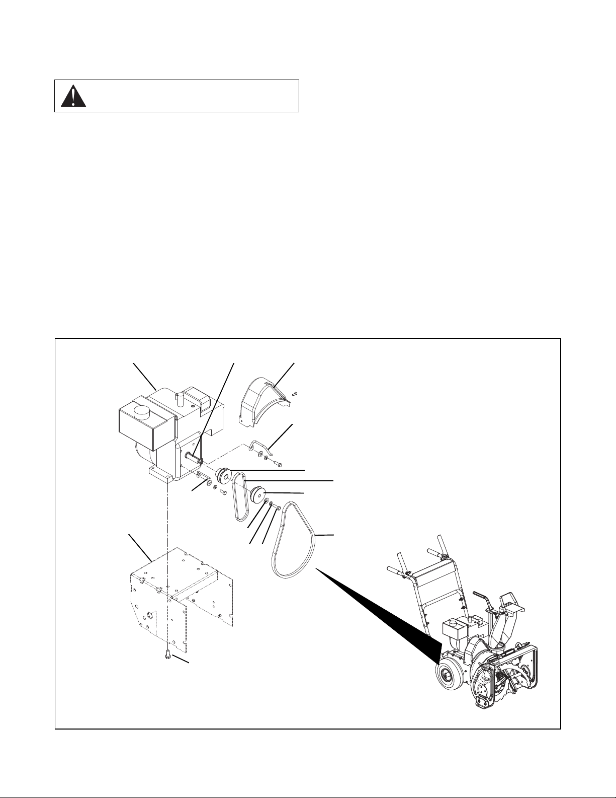
Figure 22
1
2 43
5
5
6
7
8
9
10
11 12
13
1.Frame
2. Engine
3. Engine Shaft
4. Belt Cover
5. Belt Finger
6. Drive Pulley
7. Drive Belt
8. Attachment Pulley
9. Attachment Belt
10.Flat Washer
11. Locking Washer
12.Bolt
13.Engine Mounting Bolt
(typical of 4)
PS0330-1
)S7350
Figure 22
10.Remove the four mounting bolts from the engine
base.
11.Lift engine from mounting base and set to side.
CAUTION: Remove fuel from fuel tank before
removing engine.
1. Drain gasoline.
2. Separate blower housing from frame (see Figure
7).
3. Block frame front and back so it will not tip.
4. Remove belt cover.
5. Remove attachment belt and drive belt from the
engine pulleys. For instructions, see "
Attachment
Drive Belt Rep l ac em e nt" on page 15 and "Traction
Drive Belt Replacement" on page 16.
6. Remove bolt, lock washer, and flat washer
securing pulleys to engine shaft.
7. Loosen and slide pulleys off engine shaft.
8. If the unit has a bracket at the top of the engine for
chute/deflector controls, unbolt it.
9. If the unit is equipped with electric starting, remove
the starter.
7.3 ENGINE INSTALLATION
Figure 22
1. Block frame so it will not tip.
2. Position engine in frame.
3. Insert mounting bolts and tighten.
4. If equipped with electric start, install the starter.
5. Re-attach any brackets for chute/deflector controls.
6. Install pulleys on engine shaft.
7. Install belts. For instructions, see "Attachment
Drive Belt Replacement" on page 15 and "Traction
Drive Belt Replacement" on page 16.
8. Adjust engine pulleys to align with attachment and
drive pulleys.
9. Tighten pulleys
10.Install belt cover.
11.Connect blower housing to frame.
7 - 25
Page 26
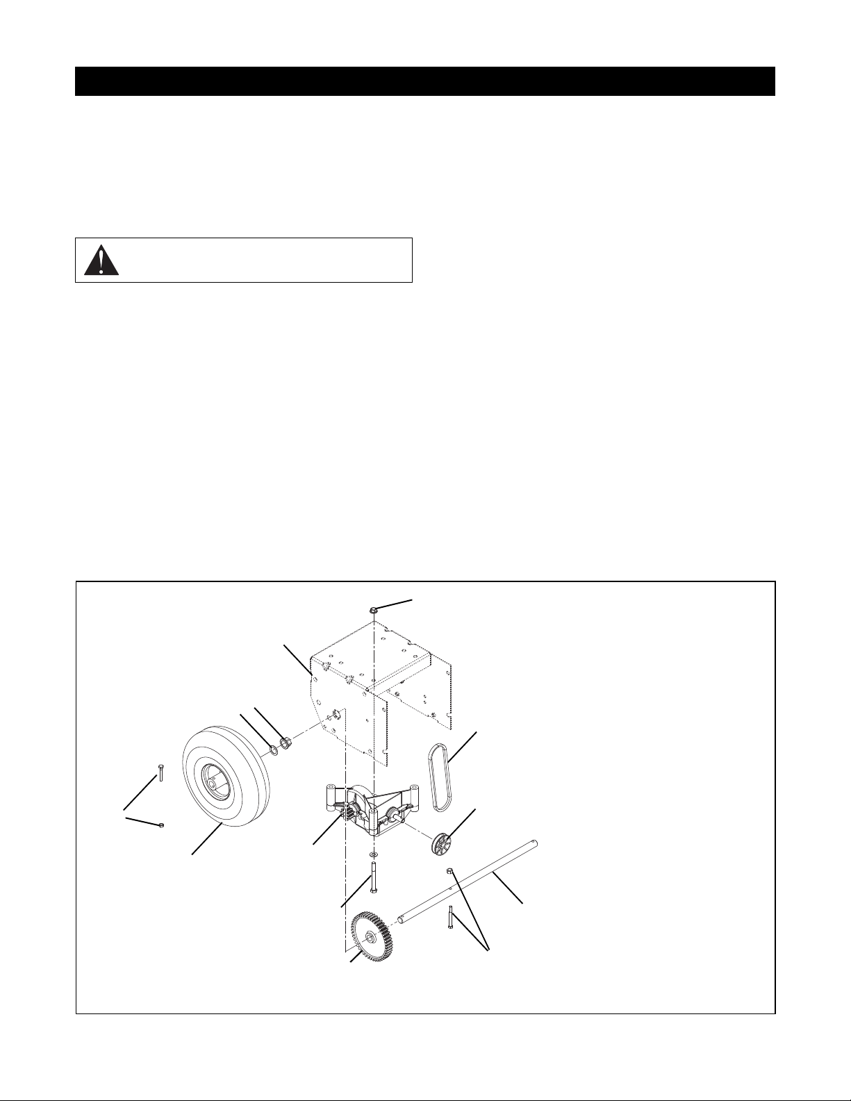
The transmission has no dealer-serviceable parts. If
SECTION 8 - TRANSMISSION
Figure 23
PS0330_2
1
2
3
4
5
6
7
8
9
11
12
13
1.Frame
2. Locking Nut (typical of 3)
3. V-Belt (stretch fit)
4. Transmission Pulley
5. Axle Shaft
6. Bolt and Nut
7. Gear
8. Transmission Mounting Bolt
and Flat Washer (typical of 3)
9. Transmission
10.Wheel
11. Bolt and Nut
12.Flat Washer
13.Axle Bushing (1 each side)
10
defective, it must be replaced as a unit.
8.1 TRANSMISSION REMOVAL
Figure 23
1. Shut off engine, remove key, disconnect spark plug
wire, and allow unit to cool completely.
CAUTION: Remove fuel from fuel tank before
placing unit in service position.
2. Drain gasoline.
3. Place machine on a level surface, and tip up into
service position (see
4. Remove both wheels.
5. Remove nut and bolt holding axle gear in place.
6. Remove axle bushings. Discard if worn.
7. Remove axle
8. Remove drive belt from transmission pulley
9. Remove bolts securing transmission to frame
10.Remove transmission.
Figure 4 on page 12).
8.2 TRANSMISSION INSTALLATION
Figure 23
IMPORTANT: Before beginning installation, make sure
that:
• Key is removed from switch.
• Spark plug is disconnected.
• Machine is cool.
• Gasoline has been drained from tank.
1. If necessary, place machine on a level surface, and
tip up into service position (see
12).
2. Bolt transmission to frame.
3. Attach drive belt to transmission pulley.
IMPORTANT: Make sure drive belt is properly aligned
with transmission pulley and engine pulley.
4. Install axle gear on axle. Do not tighten nut onto
bolt.
5. If necessary, install new axle bushings.
6. Install axle.
7. Align axle gear with transmission sprocket as
required.
8. Tighten nut onto bolt holding gear to axle.
9. Install wheels.
Figure 4 on page
8 - 26
Page 27
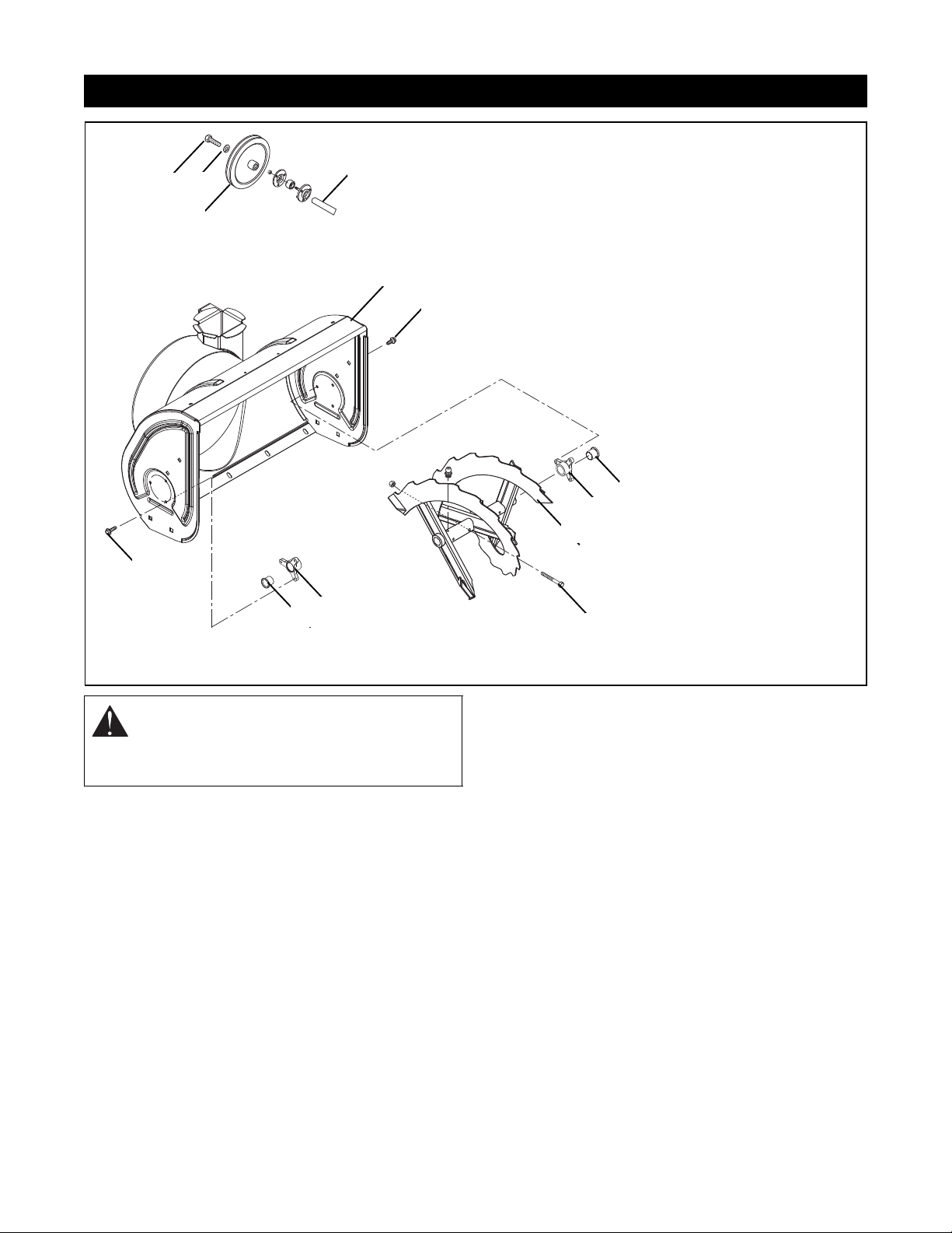
SECTION 9 - AUGER/IMPELLER
Figure 24
1
2
3
4
5
6
6
7
8
8
7
9
10
1.Auger Drive Pulley
2. Bolt
3. Locking Washer
4. Auger Drive Shaft
5. Blower Housing
6. Tapping Screw (3 each side)
7. Flange Bushing
8. Shaft Bushing
9. Auger
10.Shear Bolt
PS0361-1
WARNING: Stop engine, remove key, wait for
moving parts to stop and remove wire from
spark plug before leaving operator’s position
and attempting to maintain or inspect auger.
9.1 AUGER/IMPELLER REPAIR
1. Place machine on a flat, level surface.
NOTE: Placing blocking under the runners on the
blower housing may make auger removal easier.
2. Remove bolt holding auger drive pulley to shaft
and remove pulley.
3. Remove three tapping screws holding shaft
bushing to blower housing and remove flange on
each side.
4. Grasp auger assembly and pull gear case and
auger/impeller assembly free of housing.
5. Remove shear bolts and remove auger from shaft.
6. Check all parts for wear or replacement.
7. Assemble, using reverse procedure.
9.2 SHEAR BOLTS
IMPORTANT: Use only Ariens shear bolts for
replacement. Use of any other type of shear bolt may
result in severe damage to unit.
Occasionally an object may enter auger/impeller
housing and jam auger, breaking shear bolts which
secures auger to shaft. This prevents damage to gear
drive by allowing auger to turn freely on shaft.
To replace shear bolt:
1. Slide auger outward and align hole in shaft with
hole in auger (
pins and shear bolts will line up.
2. Drive the new shear bolt through hole (if shear bolt
was broken this will drive remaining part from
shaft).
3. Secure with nut.
9 - 27
Figure 24). The holes in shaft for roll
Page 28
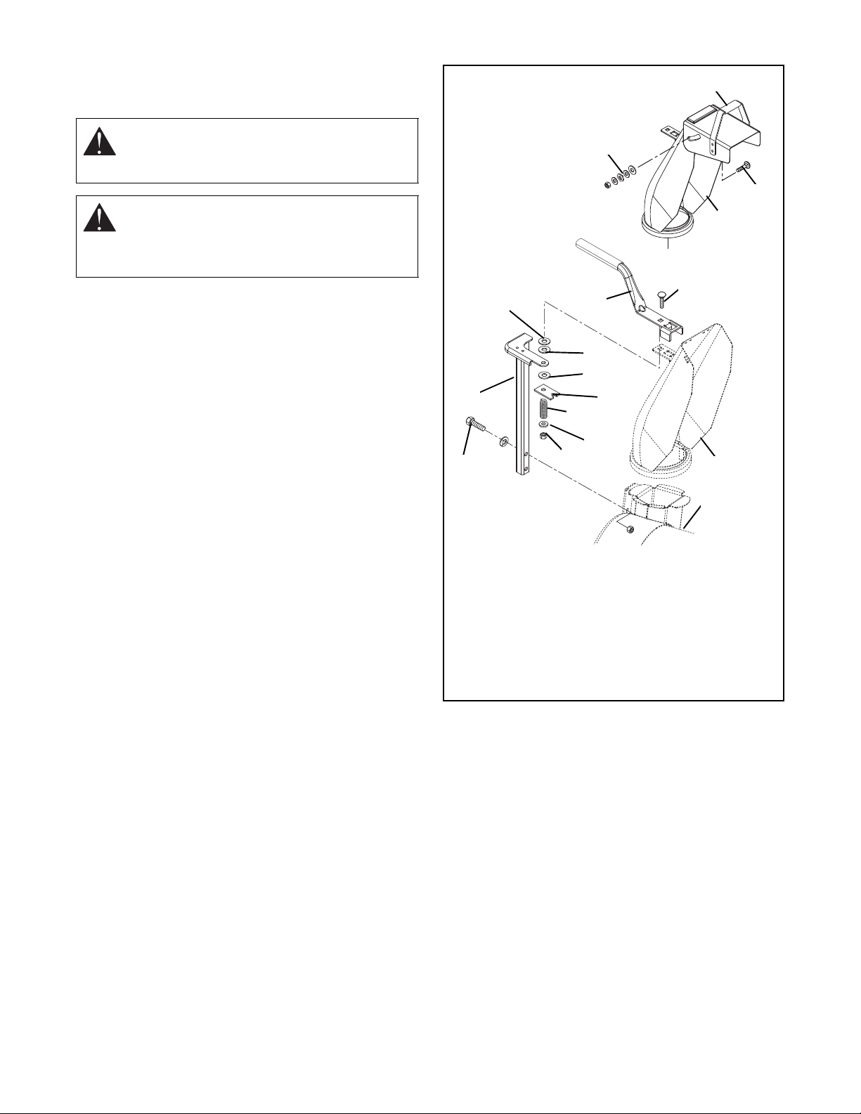
9.3 DISCHARGE CHUTE
1
1
2
3
4
5
6
7
8
9
10
11
6
12
12
13
14
15
1.Discharge Chute
2. Handle
3. Bolt
4. Nut and Washers
5. Blower Housing
6. Bolt with Washer
7. Pedestal
8. Locking Nut
9. Flat Washer
10.Spring
11.Friction Plate
12.Friction Washer
13.Flat Washer
14.Bolt
15.Direction Handle
Figure 25
Ps0373-1
Models 939001 and 939002.
Figure 25
WARNING: DO NOT put hands or feet near
or under rotating parts. Keep clear of
discharge opening at all times.
WARNING: NEVER direct discharge of
material toward bystanders nor allow anyone
in front of equipment while unit is in operation.
Be familiar with area of operation.
1. Remove bolts holding chute pedestal to blower
housing.
2. Lift chute and pedestal from housing.
3. Check parts for wear, and replace as needed.
4. Assemble in reverse order.
9 - 28
Page 29
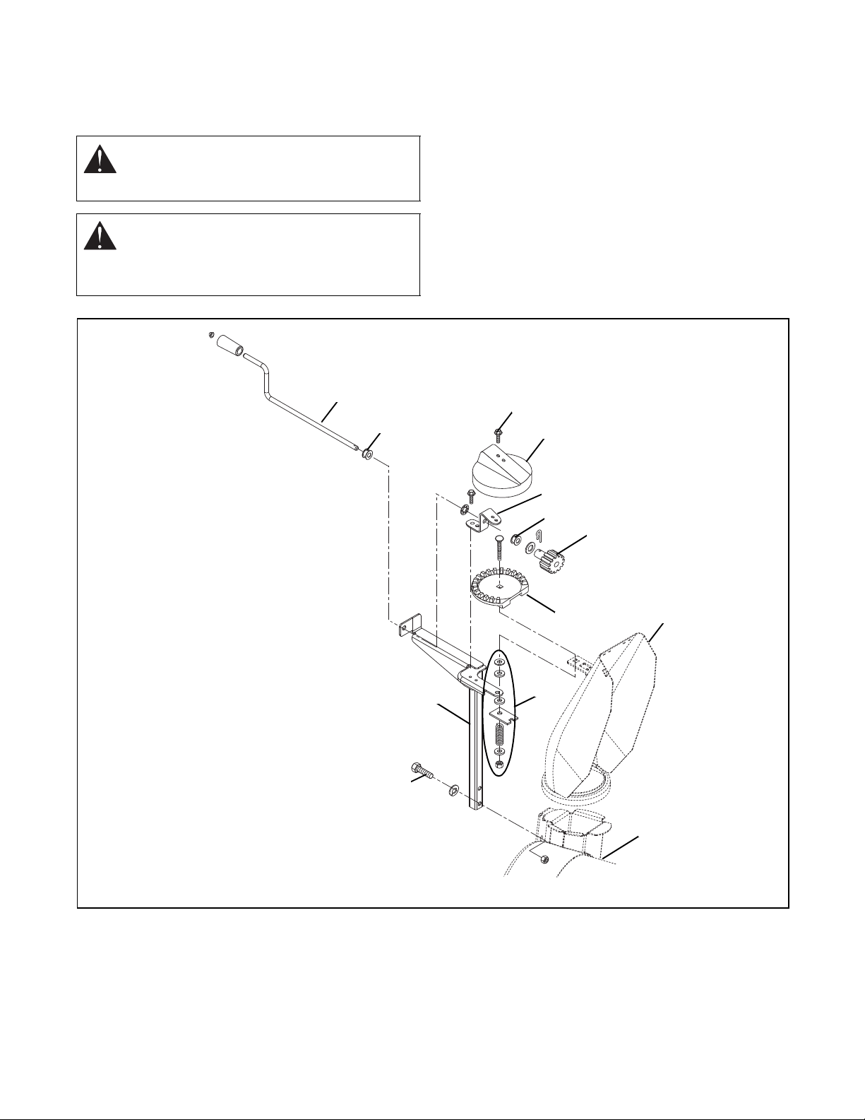
9.4 DISCHARGE CHUTE CRANK
Figure 26
1
2
3
4
5
6
7
8
9
10
11
12
13
1.Crank Shaft
2. Bushing
3. Self-Tapping Screw
4. Gear Cover
5. Pinion Gear Bracket
6. Bushing
7. Pinion Gear w/Spring Clip
8. Chute Gear
9. Discharge Chute
10.Blower Housing
11.See Figure 25
12.Bolt w/Lock Washer
13.Pedestal
PS0373-2
Model 939300 only or if kit 73900100, Crank Kit, is
installed.
Figure 26
WARNING: DO NOT put hands or feet near
or under rotating parts. Keep clear of
discharge opening at all times.
WARNING: NEVER direct discharge of
material toward bystanders nor allow anyone
in front of equipment while unit is in operation.
Be familiar with area of operation.
1. Remove the cover over the chute gear.
2. Remove the spring clip from the pinion gear, and
slide the gear, thrust washer, and bushing off the
crank shaft.
3. Slide the crank shaft back through the pinion gear
bracket and bracket on the pedestal weldment.
4. Remove bolts holding chute pedestal to blower
housing.
5. Lift chute and pedestal from housing.
NOTE: The chute gear is attached to the chute and is
removed with the chute and pedestal.
6. Check parts for wear, and replace as needed.
7. Assemble in reverse order.
9 - 29
Page 30
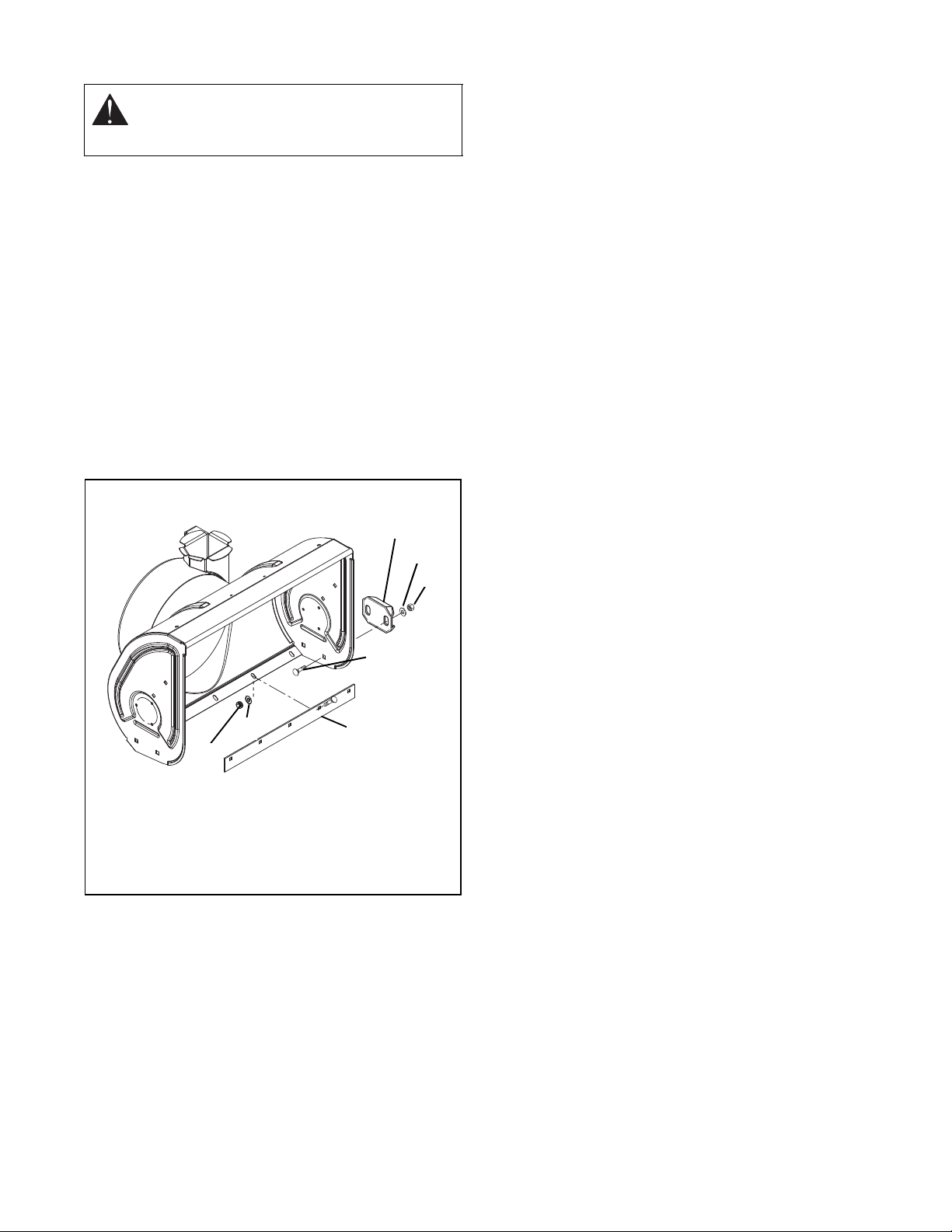
9.5 RUNNER AND SCRAPER
Figure 27
1
2
3
4
5
6
7
1.Runner
2. Flat Wash er
3. Locking Nut
4. Bolt
5. Scraper
6. Locking Nut
7. Flat washer
PS0361_2
CAUTION: Adjust auger/impeller housing
height to clear gravel or crushed rock
surfaces.
Runners should be adjusted as co nditio ns requi re
(
Figure 27). Raising or lowering runners controls
distance scraper blade is held above surface being
cleared.
When operating machine on gravel surface, lower
runners so the housing will not pick up gravel. On
concrete, blacktopped or packed down snow surfaces,
raise runners so that scraper blade scrapes clean.
Position unit on a flat level surface. Adjust runners by
inserting a spacer of desired thickness under center of
scraper blade, loosen hardware, slide runners to flat
surface and retighten hardware.
NOTE: Above method keeps housing level by adjusting runners equally. Uneven runners make machine
difficult to steer and results in uneven clearing.
9 - 30
Page 31
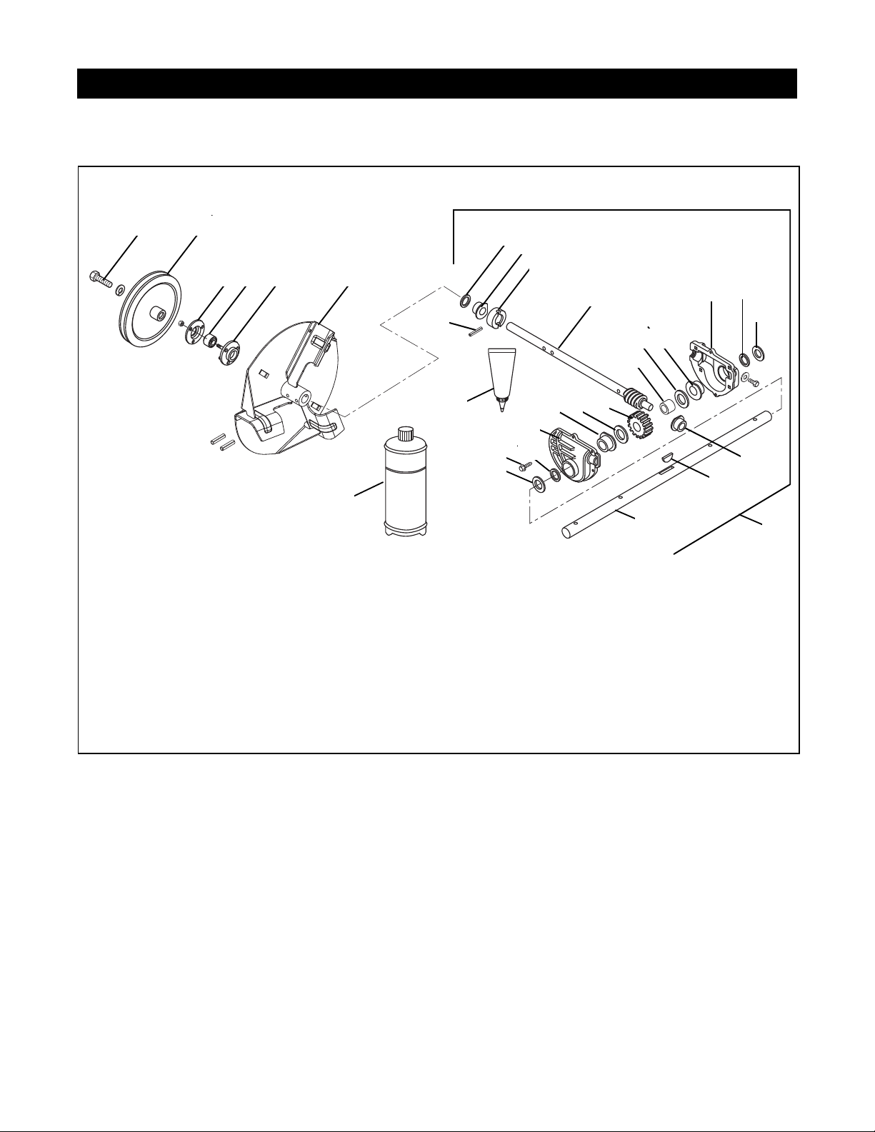
10.1 ALUMINUM GEAR CASE
SECTION 10 - GEAR CASE
1
2
3 4
5
6
8
9
10
11
12
13
14
1516
17
18
1920
21
2223
24
25
26
27
29
30
7
1.Bolt w/Lock Washer
2. Pulley
3. Bearing Flange
4. Ball Bearing
5. Bearing Flange
6. Impeller (12 in.)
7. Groove Pin
8. Oil Seal
9. Flange Bushing
10.Thrust Collar
11. Shaft and Worm Gear
12.Flat Washer
13.Oil Seal
14.Gear Case (Left Hand)
15.Flange Bushing
16.Flat Washer
17.Sleeve Bushing
18.Gear
19.Flat Washer
20.Flange Bushing
21.Gear Case (Right Hand)
22.Oil Seal
23.T app ing Sc rew (typical of 6)
24.Flat Washer
25.Flange Bushing
26.Woodruff Key
27.Auger Shaft
28.Gear Case Assembly
29.Loctite Gasket 518
30.L2 Lube (16 oz)
28
Figure 28
PS0381
1. Remove auger/impeller and gear case from
housing
(see Auger/Impeller Repair on page 27).
2. Remove six tapping screws that hold right and left
gear case halves together (
Figure 28).
3. If flange bushings need replacement:
a. Remove oil seals from outside of gear case
halves with a screwdriver.
b. Very lightly, press flange bushings from
outside in with a bearing driver. Make sure the
flat on the flange of bushing fits in the inside
notch of the case.
c. Replace oil seals.
4. Check all internal parts for wear, and replace if
necessary.
NOTE: A woodruff key holds the worm gear on rake
shaft.
5. Slide bronze bushing off front of worm gear shaft.
Replace if necessary. A flat on the bushing flange
positions the bearing inside the gear case.
6. Replace the seal behind the rear bronze bushing. It
fits into a groove in gear case.
7. Replace the rear bushing if necessary. It is a larger
diameter than one in front, but it is identical in
design.
8. If thrust collar needs replacing, drive out groove pin
in direction of least resistance.
9. Inspect worm gear shaft for burrs or black
coloration. If either show up, replace shaft.
10 - 31
Page 32

10.Before re-assem bl ing gear ca se :
a. Clean mating surfaces of gear case.
b. Apply Loctite gasket to cleaned surface.
c. Allow to cure for 24 hours.
d. Make sure the flats on the bushings are in their
proper places.
11.Reassemble gear case.
After assembly is complete you should be able to
turn input shaft freely.
12.Fill gear case with lubricating oil (Ariens L-2, P/N
00008000):
a. Remove filler pl ug.
b. Fill gear case with oil.
c. With machine sitting level, check oil level.
Lubricating oil should be even with filler plug
hole.
NOTE: Inserting a wire into the hole may be necessary
to check level. Over-lubricating will not damage the
gear case.
Service Part s List
Order the following parts through your Dealer:
Part No. Description
00036800 Ariens Hi-Temp Grease (3, 3 oz.
cartridges)
21533400 Spark Plug (939001, 002)
21533500 Spark Plug (939300)
07200108 Impeller Belt
07200109 Stretch Fit Traction Belt
53200500 Shear Bolts
10 - 32
Page 33

Ariens Company
655 West Ryan Street
P.O. Box 157
Brillion, WI 54110-0157
920-756-2141
Fax 920-756-2407
www.ariens.com
1 - 33
 Loading...