

Page 1

■'iT'
935000 SERIES 8 & 11 H.P. YARD TRACTORS
Model 935004 (YT8-32) 8 H.P.
Gear Drive with 32” Mower
Serial No. 000601 and up
Model 935003 {YT11-38) 11 H.P.
Gear Drive with 38” Mower
Serial no. 000101 and up
Model 935005 {YT11-32) 11 H.P.
Gear Drive with 32” Mower
Serial no. 000282 and up
ATTACHMENTS
Model 835004
32” Mower Attachment
Serial no. 000101 and up
Model 835005
38” Mower Attachment
Serial no. 000101 and up
"Ifk
/4 MESSAGE TO THE ARIENS CUSTOMER. . .
Welcome to the world of Ariens equipment. We are
pleased that you have selected Ariens and sincerely
believe you have purchased the best equipment
available. The care you give your new Ariens equip
ment will greatly determine the satisfaction and service
life you will obtain from it. Use this manual and the
engine manual supplied, as your guide. By observing
the instructions and suggestions in these manuals,
your Ariens equipment will serve you well for many
years.
Your Ariens dealer will be happy to supply any service
or advice which may be required to keep your Ariens
equipment operating at peak_fi£ficiency. He stocks
genuine Ariens parts and lubricants; manufactured
with thé same precision and skill as the original equip
ment. His factory trained staff is kept well informed on
(Törtens
(>ART NUMBER 35318A
COMPANY BRILLION, WISCONSIN 54110
"A CUT ABOVE THE REST!"
the best methods of servicing Ariens equipment and is
ready and able to serve you. If engine repairs or ser
vices are required, they can be obtained from an Ariens
dealer or from an authorized engine manufacturer's
service station.
Should service be required on equipment, be prepared
to supply the serviceman with the Model Number and
Serial Number of the equipment and the engine, as well
as a full description of the trouble encountered.
Finally, your local Ariens dealer is in the best position to
answer your questions and service equipment. If for
some reason he is unable to satisfy your requirements,
assistance is always available from the Consumer
Services, Ariens Company, Brillion, Wisconsin 54110.
Telephone; (414) 756-2141.
PRINTED IN U.S.A.
Page 2

INSTRUCTIONS FOR SAFE OPERATION
1. know the controls and how to stop quickly. READ
THE OWNER'S MANUAL.
2. Do not allow children to operate the vehicle. Do
not allow adults to operate it without proper in
struction.
3. Do not carry passengers. Keep children and pets a
safe distance away.
4. Clear the work area of objects which might be
picked up and thrown.
5. Sit on seat, disengage traction and attachment
power and shift into neutral before attempting to
start the engine.
6. Disengage power to attachment, stop the engine
and place speed selector to "NEUTRAL” position
and set parking brake lock before leaving the
operator's position.
7. Disengage power to attachment and stop the
engine before making any repairs or adjustments.
8. Disengage power to attachment when transpor
ting or or not in use.
9. Take all possible precautions when leaving the
vehicle unattended, such as disengaging the at
tachment power, lowering the attachment, shif
ting into neutral, setting the parking brake lock,
stopping the engine and removing the key.
10. Do not stop or start suddenly when going uphill or
downhill. Operate up and down the face of steep
slopes; never across the face. If you cannot back
up the hill, DO NOT operate the tractor on it. It is
too steep for safe operation.
11. Reduce speed on slopes and in sharp turns to pre
vent tipping or loss of control. Exercise extreme
caution when changing direction on slopes.
1 2. Stay alert for holes in the terrain and other hidden
hazards.
1 3, Use care when pulling loads or using heavy equip
ment.
a. Use only approved hitch points
b. Limit loads to those you can safely control.
c. Do not turn sharply. Use care when backing.
d. Use counterweight when suggested in the 1
tor owner's manual or in the attachment
owner's manual.
14. Watch out for traffic when crossing or near road
ways.
15. When using any attachments, never direct
discharge of material toward bystanders nor allow
anyone near the vehicle while in operation.
16. Handle gasoline with care—it is highly flammable.
a. Use approved gasoline container.
b. Never remove the cap of the fuel tank or add
gasoline to a running or hot engine, or fill the
fuel tank indoors. Wipe up spilled gasoline.
1 7. Never store the equipment with gasoline in the
tank inside a building where fumes may reach an
open flame or spark. Allow the engine to cool
before storing in any enclosure.
18. Exhaust fumes are dangerous. Do not run the
engine indoors.
19. Keep the vehicle and attachments in good
operating condition, and keep safety devices in
place.
20. Keep all nuts, bolts, and screws tight to be sure
the equipnnent is in safe working condition.
21. To reduce fire hazard, keep the engine free of
grass, leaves, or excessive grease.
22. The vehicle and attachments should be stopped
and inspected for damage after striking a foreign
object, and the damage should be repaired before
restarting and operating the equipment, see items
6 & 7.
23. Do not change the engine governor settings or
overspeed the engine.
24. When using the vehicle with mower, proceed as
follows:
a. Mow only in daylight or in good artificial light.
b. Shut the engine off when unclogging chute.
c. Check the blade mounting bolts for proper
tightness at frequent intervals.
d. Always look behind you before backing up.
THIS SAFETY ALERT SYMBOL IDENTIFIES IMPORTANT SAFETY INFORMA
TION IN THIS MANUAL. WHEN YOU SEE THE SYMBOL BE ALERT TO THE
POSSIBILITY OF INJURY AND CAREFULLY READ THE INFORMATION THAT
A
FOLLOWS.
A
-2-
Page 3
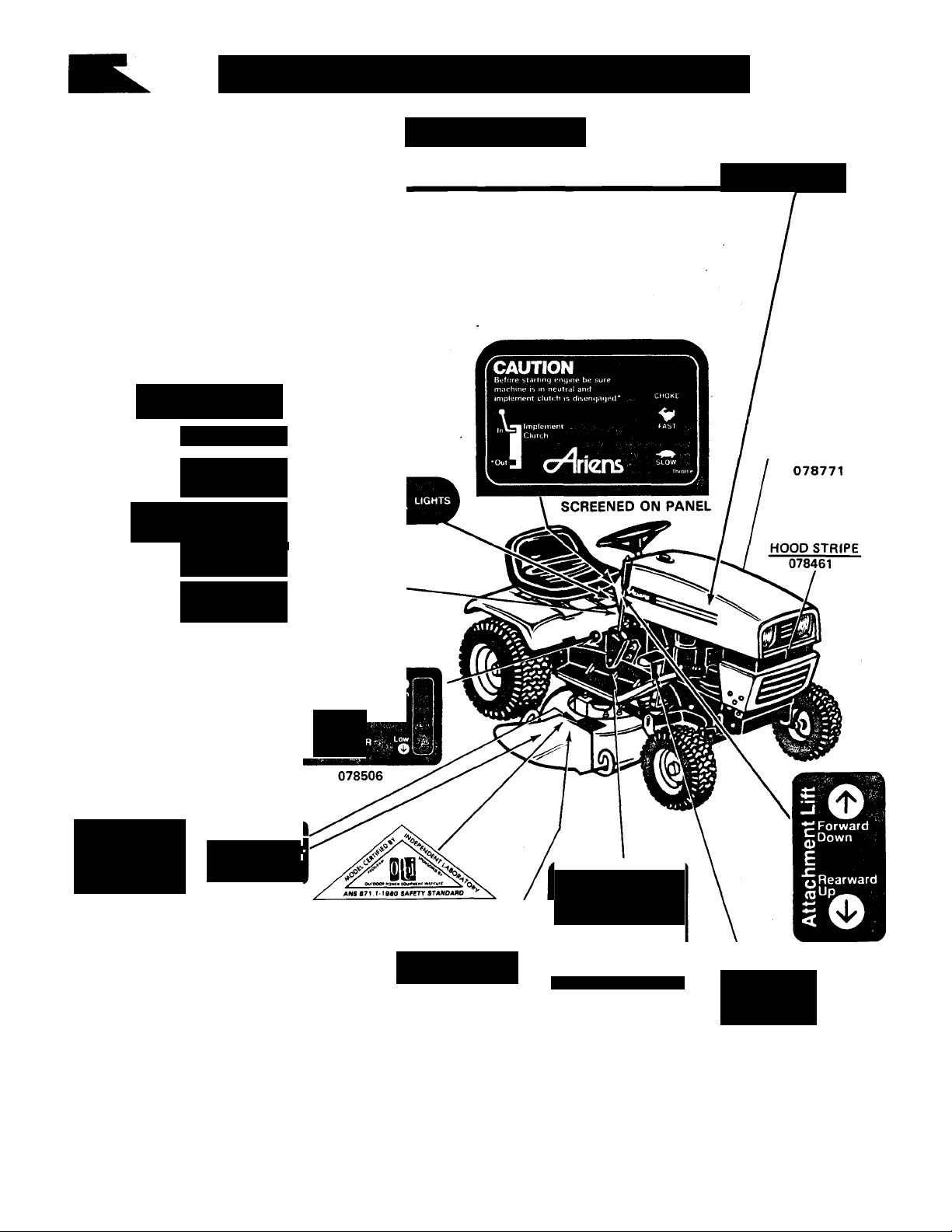
BE AWARE OF SAFETY DECALS
078810 R.H. 078813 R.H.
YT8 YT11
(935004 only) (935003, 5 only)
C7^riens\TFi!1l '
078809 L.H. 078812 R.H.
YT8 YTI1
(935004 only) (935003, 5 only)
CAUTION
■ Hc.Hlooer.itorsfn.-inuai
» Keep bfiK-irts if> place
• Keep people ,iru3 pels a safe
GO
• Heie.ise pjrktnq bfake ‘ . .
• Oi'press cloif h pedal • ■
• Sliift lo rtesiit'd speed • ’ ,
• Slowly'eie.ise dulcb
STOP
• Ofpiess ciuiicn pedal
• Oepress Bf.iKe pecla'
• Beto'p le.iviiiq opeirfto's
d);
posdton
Shift to neotr.p ^ ■
f riqaqe p.ifkirq brake
Oisemi.iqi' aliachment clulch
Shut off Ei'qine
Upmove iqnthon key
SERVICING
• Wait loi all movement to stop
• niscormecf spark plug wire ■
• Hi’loie lipptriq unit, oraii'
qas tank and remove • . '
cT^riens^y
^X-N-FU)P^
078547
ROTATING PARTS
• Keep hands and feet
away from under
entire housing
• Do not operate mower
unless grass catcher is
attached or mower guard
is in operating position
078735
078556
ROTATING PARTS
K««p narvls and taol away from ira
entir« horoing
Do not operate mower rakesa iraM
caitfwr !• attached nr mower guard
■a in novating paaiflSi
078779
-■v-J'
NO STEP
078508
-3-
Parking Brake
Depress Brake Pedal
Then Engage Parking
Brake Lock
Disengage Engage
078738
Depress brake pedal
then lift parking
brake lock.
ENGAGED &
©DISENGAGED
078584
078505
Page 4
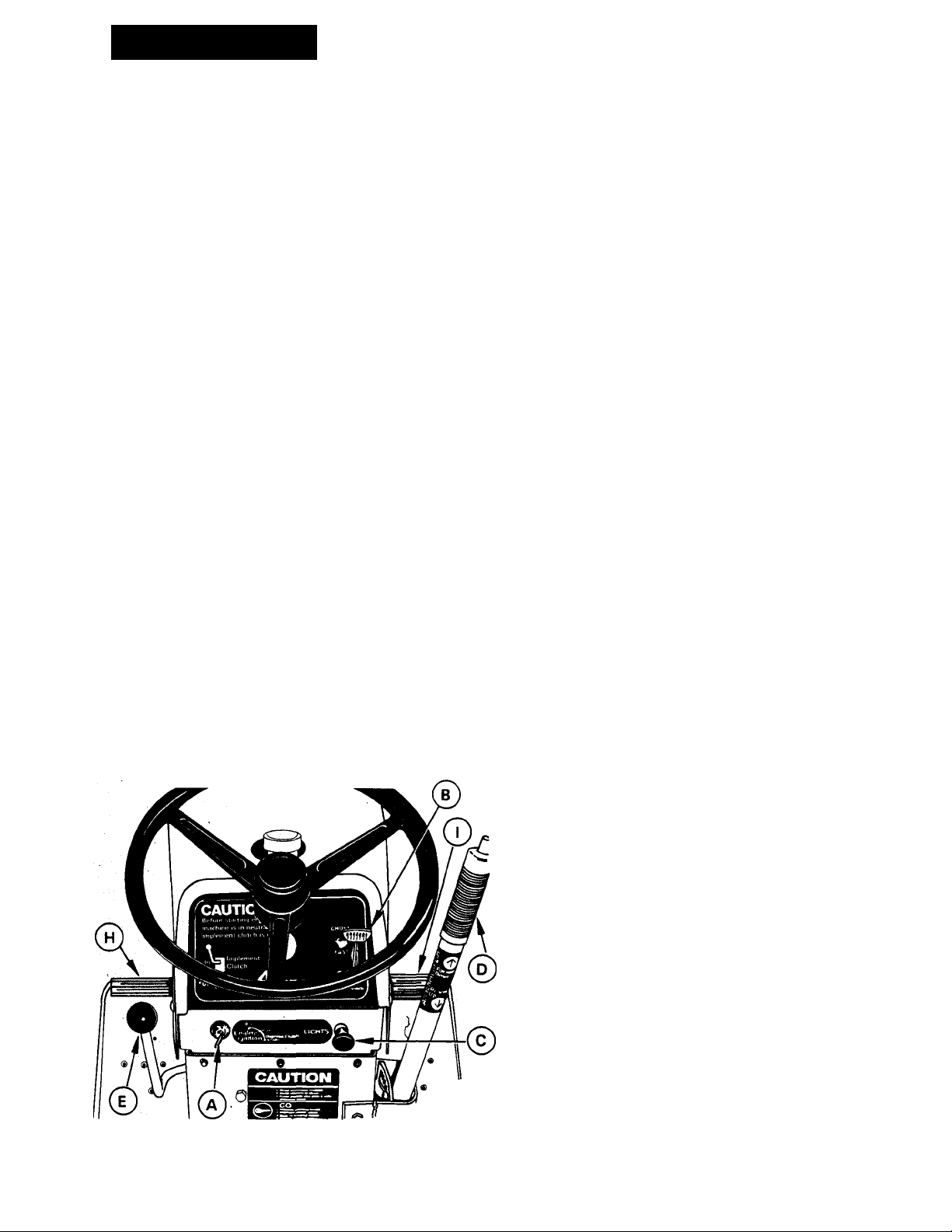
CONTROLS
@IGNITION AND STARTER SWITCH - FIGURE 1 (e)IMPLEMENT POWER CLUTCH - FIGURE 1
The ignition and starter switch has three positions:
"OFF", "RUN", and "START". Start the engine by
turning the key fully clockwise to "START" position
and then release the key as soon as the engine starts.
Stop the engine by turning the key counterclockwise to
the "OFF" position.
THROTTLE-CHOKE CONTROL LEVER - FIGURE 1
This control operates both the throttle and choke.
When starting a cold engine, raise the lever past the
offset and into the "CHOKE" position. After the engine
has started, lower the lever to the throttle operating
range and allow the engine to warm at 14 throttle.
Select the appropriate engine speed in the throttle
range after the engine has warmed up.
NOTE; UNLESS OTHERWISE SPECIFIED, THE AT
TACHMENTS SHOULD BE OPERATED AT FULL
THROTTLE. THE THROTTLE IS NOT TO BE USED TO
SELECT DESIRED TRAVEL SPEEDS. OPERATE AT
FULL THROTTLE AND REGULATE GROUND SPEED
WITH THE GEAR SHIFT LEVER.
LIGHT SWITCH - FIGURE 1
©
Turn lights on by pulling the control knob out. Turn
lights off by pushing the knob in.
ATTACHMENT LIFT LEVER - FIGURE 1
©
To raise the attachment, depress thumb button, pull
the lever to the rear, and release thumb button. This
will hold the attachment in the raised position. When
using the mower attachment; select the "notch" that
allows the mower to cut at the desired height.
To lower the attachment, pull the lever to the rear,
depress the button to release the latch and allow the
lever to move forward.
The Implement Power Clutch is used to operate the at
tachments. Push the lever forward to engage the clutch
and drive the attachment. Pull the lever rearward to
disengage the clutch and stop the attachment. The
lever must be in the rear (disengaged) position to start
the engine. THIS IS A SAFETY FEATURE. The engine
will not start until the lever has been placed in the
disengaged position.
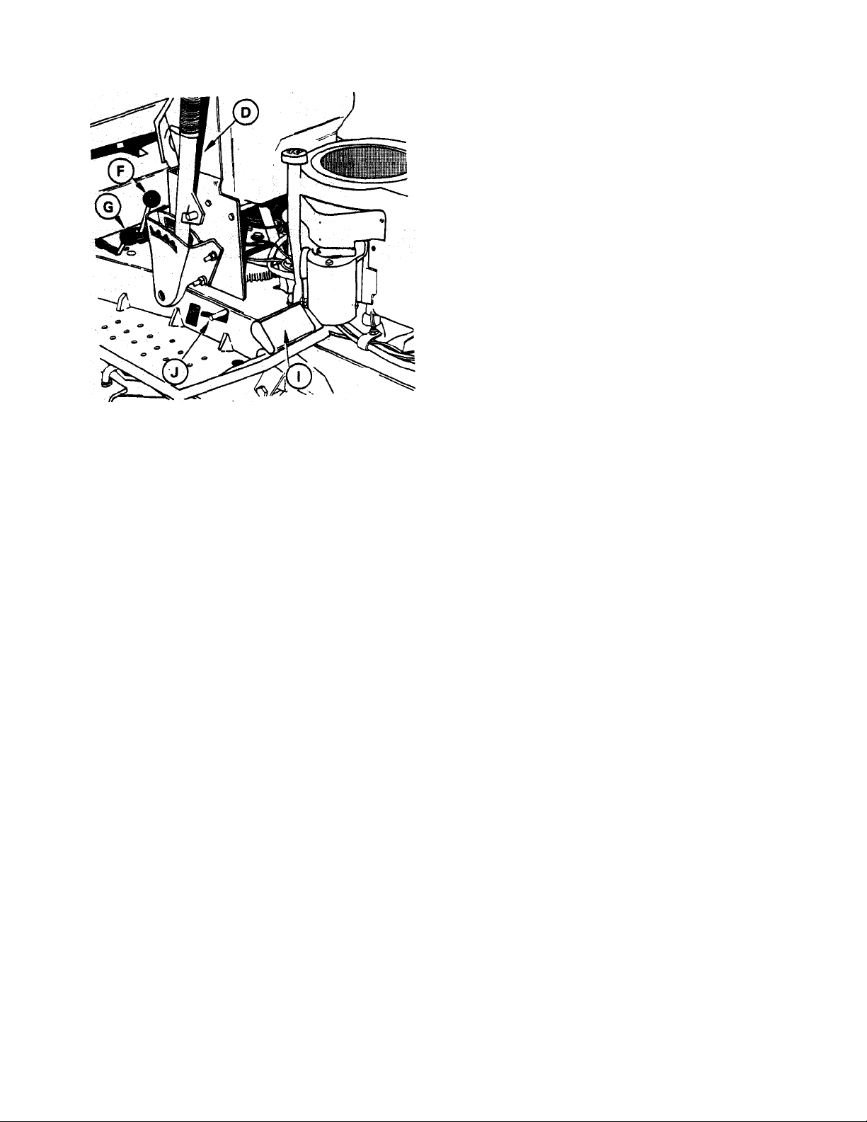
(7) SPEED SELECTOR LEVER - FIGURE 2
The Speed Selector Lever is used to select any of three
forward gears or one reverse gear. The markings " 1,2,
3" and "R" on the floor plate indicate the locations of
the gears. The slowest forward gear is indicated by
"1", the secondary gear, "2" and the fastest gear,
"3". The "R" indicates reverse. The Speed Selector
Lever must be in the "NEUTRAL" position as shown in
Figure 2 to start the engine. THIS IS A SAFETY
FEATURE.
@ HIGH-LOW SPEED RANGE SELECTOR - FIGURE 2
The High-Low Speed Selector gives a choice of six for
ward speeds; three in "HIGH" range; and three in
"LOW" range. The speed in reverse gear is the same in
both ranges. See "SPECIFICATIONS", page 40.
CLUTCH PEDAL - FIGURE 1
©
Depressing the Clutch pedal disengages the transaxie
from the engine and permits shifting the speed selector
to any desired gear. Always release the clutch pedal
slowly for smooth acceleration. Do not allow foot to
rest on pedal except when clutching.
IMPORTANT: ALWAYS DEPRESS CLUTCH PEDAL TO
EASE ENGINE STARTING. DEPRESSING CLUTCH
PEDAL RELEASES PARKING BRAKE. BE READY TO
APPLY FOOT BRAKE WHEN STARTING FROM PARK
POSITION.
FIGURE 1
BRAKE PEDAL - FIGURE 1
o
Depressing the brake pedal applys pressure to the disk
brake and stops the tractor (with the clutch depressed).
Be sure to depress clutch pedal to disengage the clutch
before braking. Brake will not stop tractor without
depressing clutch pedal.
PARKING BRAKE LOCK - FIGURE 3
©
A Parking Brake Lock is provided to prevent the tractor
from moving when parked or left unattended. To lock
the brake, pull the parking brake lock up with the pedal
fully depressed. Then release the brake pedal. Figure 3
shows the parking brake lock engaged. Clutch pedal
must not be depressed when locking brake. Park"^~>
brake lock may be disengaged by depressing eit
brake or clutch pedal.
Page 5

IMPORTANT: ENGAGE THE BRAKE LOCK BEFORE
DISMOUNTING FROM THE TRACTOR OR ANY TIME IT
IS LEFT UNATTENDED.
A
CAUTION; WHEN USING TRACTOR OR ATTACH
MENT FOR THE FIRST TIME USE LOW RANGE SPEEDS
AND LOWER GEARS TO MAKE SURE OF YOUR CON
TROLS.
OPERATION
WHEN USING ATTACHMENTS
A rear weight box and wheel weights are available to
increase traction when using the Sno-Thro or the front
blade attachments. Rear tire chains are also available
for use in snow conditions.
FIGURE 2
4. Raise Throttle-Choke Control Lever ® Figure 1,
past the offset in the slot to the "CHOKE" posi
tion.
NOTE: OPERATOR MUST BE ON SEAT TO START
UNIT. TRACTOR HAS A SEAT SWITCH FOR SAFETY.
NOTE: TOO MUCH REAR WHEEL TRACTION WILL
RESULT IN DRIVE TRAIN OVERLOAD AND POSSIBLE
DAMAGE. THEREFORE: WEIGHT BOX LIMIT IS 125
LBS. REAR TIRE CHAINS ARE NOT TO BE USED ON
DRY SOIL OR GRAVEL.
PRE-STARTING INSPECTION
1. Check oil in engine crankcase. Add oil as required
to maintain proper level. See "LUBRICATION"
section.
2. Check fuel supply. Fill with clean, fresh regular or
unleaded gasoline only. See "LUBRICATION"
section.
3. Check air cleaner and tire pressures.
4. Check for engine, transmission or differential oil
leaks. See your Ariens dealer for repairs.
5. Make visual checks regarding safety precautions,
obstructions and maintenance.
STARTING THE ENGINE
Use the following procedure to start the engine.
1. Depress Clutch Pedal (h) and hold the tractor in
position by depressing the Brake pedal © .
2. Place the Speed Selector Lever 0 in the
"NEUTRAL" position as shown in Figure 2.
5. Turn ignition key ® shown in Figure 1 clockwise
all the way. Release key as soon as the engine
starts and gradually lower the Throttle Choke
Control Lever past the offset until the engine runs
at Vi throttle.
NOTE: A WARM ENGINE WILL REQUIRE LESS CHOK
ING THAN A COLD ENGINE.
If the engine fails to start on the first attempt, turn key
to the "OFF" position, wait a few minutes and try
again. Do not operate starter continuously for more
than 30 seconds at a time.
Always allow engine to warm up before applying load.
In below freezing weather, allow engine to run at a fast
idle for a period of at least five minutes before moving
the tractor or starting the attachment. SERIOUS
DAMAGE TO THE ENGINE AND TRANSMISSION
COULD RESULT IF THIS PROCEDURE IS NOT
FOLLOWED.
STOPPING THE ENGINE
Always use the following procedure to stop the engine;
1. Move the Speed Selector Lever © (Figure 1) to
the "NEUTRAL" position.
2. Disengage the Implement Power Clutch © ,
Figure 1.
3. Engage Parking Brake Lock ® by depressing
the Brake Pedal © (Figure 1) and pulling up on
the Parking Brake Lock Q (Figure 3).
NOTE: THE ENGINE WILL NOT START UNLESS THE
SPEED SELECTOR LEVER IS IN THE "NEUTRAL" POSI
TION.
3. Place Implement Power CLutch Lever © Figure
1, in the rear (disengaged) position.
NOTE: THIS IS A SAFETY FEATURE. THE ENGINE
WILL NOT START UNLESS THE CLUTCH LEVER IS IN
THE DISENGAGED POSITION.
4. Lower attachment to the ground.
5. Lower Throttle Lever and allow the engine to idle
for a short period of time. DO NOT STOP A HOT
ENGINE AT HIGH SPEED AS INTERNAL ENGINE
DAMAGE COULD RESULT.
6. Turn ignition key counterclockwise to the "OFF"
position to stop the engine.
Page 6
7. BE CAREFUL: REMOVE IGNITION KEY BEFORE
DISMOUNTING FROM TRACTOR. THIS WILL
PREVENT CHILDREN AND INEXPERIENCED
OPERATORS FROM STARTING THE TRACTOR.
FIGURE 3
(YT11 Illustrated)
7. To stop the tractor, fully depress Clutch and Brake
Pedals and place Speed Selector Lever in'*
"NEUTRAL". Fully depress Brake Pedal and
engage the Parking Brake Lock when parking.^«:
leaving the tractor. (Figures 1, 2 & 3).
EMERGENCY STOPPING
Always use caution when mowing-be alert for
children, pets or obstacles in path. If necessary to make
emergency stop, step firmly on Brake Pedal and Clutch
Pedal.
A
IMPORTANT: DO NOT FORCE SPEED SELECTOR
LEVER IF GEAR DOES NOT ENGAGE. APPLY SLIGHT
PRESSURE ON THE SPEED SELECTOR LEVER WHILE
RELEASING THE CLUTCH PEDAL. THE CLUTCH
PEDAL MUST BE DEPRESSED TO ENGAGE ANY
SELECTED GEAR. DEPRESSING THE PEDAL TOO LIT
TLE WILL CAUSE GEAR CLASH AND POSSIBLE
DAMAGE TO THE TRANSMISSION. HOLD LEVER
TOWARD ENGAGED POSITION WHILE DECLUT
CHING.
WARNING:
OPERATING THE TRACTOR
1. Start the engine using the procedure explained
under "Pre-starting Inspection" and "Starting the
Engine".
NOTE: THE SPEED SELECTOR LEVER MUST BE IN THE
NEUTRAL POSITION, THE IMPLEMENT POWER
CLUTCH LEVER DISENGAGED AND THE OPERATOR
ON SEAT TO START THE ENGINE.
2. Release Parking Brake Lock 0 by depressing the
Brake ©or Clutch Pedal ® (Figure 1) until the lock
disengages.
3. Depress Clutch Pedal, place Speed Selector
Lever 0 and High-Low Range Selector ©
(Figure 1) into the desired gear and slowly release
the pedal to provide smooth acceleration.
4. Select the desired throttle speed with the
Throttle-Choke Control Lever. When operating a
power-driven attachment, operate the engine at
full throttle, (3250 RPM) unless otherwise
specified and control travel speed by selecting an
appropriate gear.
5. To raise or lower the attachment use the Attach
ment Lift Lever ®.
6. To start the attachment, engage the Implement
Power Clutch ® slowly with the engine running at
Va throttle, then increase speed to full throttle.
1. BEFORE SERVICING ANY ATTACHMENT:
a. DISENGAGE POWER.
b. SHUT OFF ENGINE. ^
c. make' sure attachment has STOPPED
REVOLVING.
d DISCONNECT ENGINE SPARK PLUG CABLE
TO PREVENT ACCIDENTAL RESTART. .
2. KEEP CHILDREN, BYSTANDERS, AND PETS OUT
OF THE WORKING AREA.
3. KEEP HANDS, FEET AND CLOTHING AWAY
FROM POWER DRIVEN PARTS.
4. KEEP ALL SHIELDS AND GUARDS IN PLACE.
GRASS BAGGING
Ariens recommends grass cutting with grass bagger
without vanes before installing vanes for increased per
formance. If performance is satisfactory without vanes
(available for mowers of 32" cutting width or less), do
not use vanes. The vanes use more power and generate
more noise. Use vanes only if satisfactory performance
cannot be obtained without them. Generally, broadleaf
grasses can be cut and bagged without vanes. The
finer grasses may require the use of vanes. In extremely
wet conditions, vanes may also be of help.
-6-
Page 7
ADJUSTMENTS
SEAT ADJUSTMENT
BRAKE PEDAL SPRING ADJUSTMENT - FIGURE 3
The seat is adjustable front or back to many positions.
Adjustment is made by loosening the two rear mountng
bolts located under rear of the seat, sliding the seat to
the most comfortable position and then tightening the
mounting bolts.
SHIFT LEVER DETENT ADJUSTMENT
Check tightness of screws holding shift handle in the
detent positions. Screws must be tightened securely.
This will eliminate jumping out of gear. See Figure 4.
SHIFT
HANDLE
• TIGHTEN DETENT SCREWS THROUGH
HOLES TO HOLD SHIFT LEVER IN GEAR .
FIGURE 4
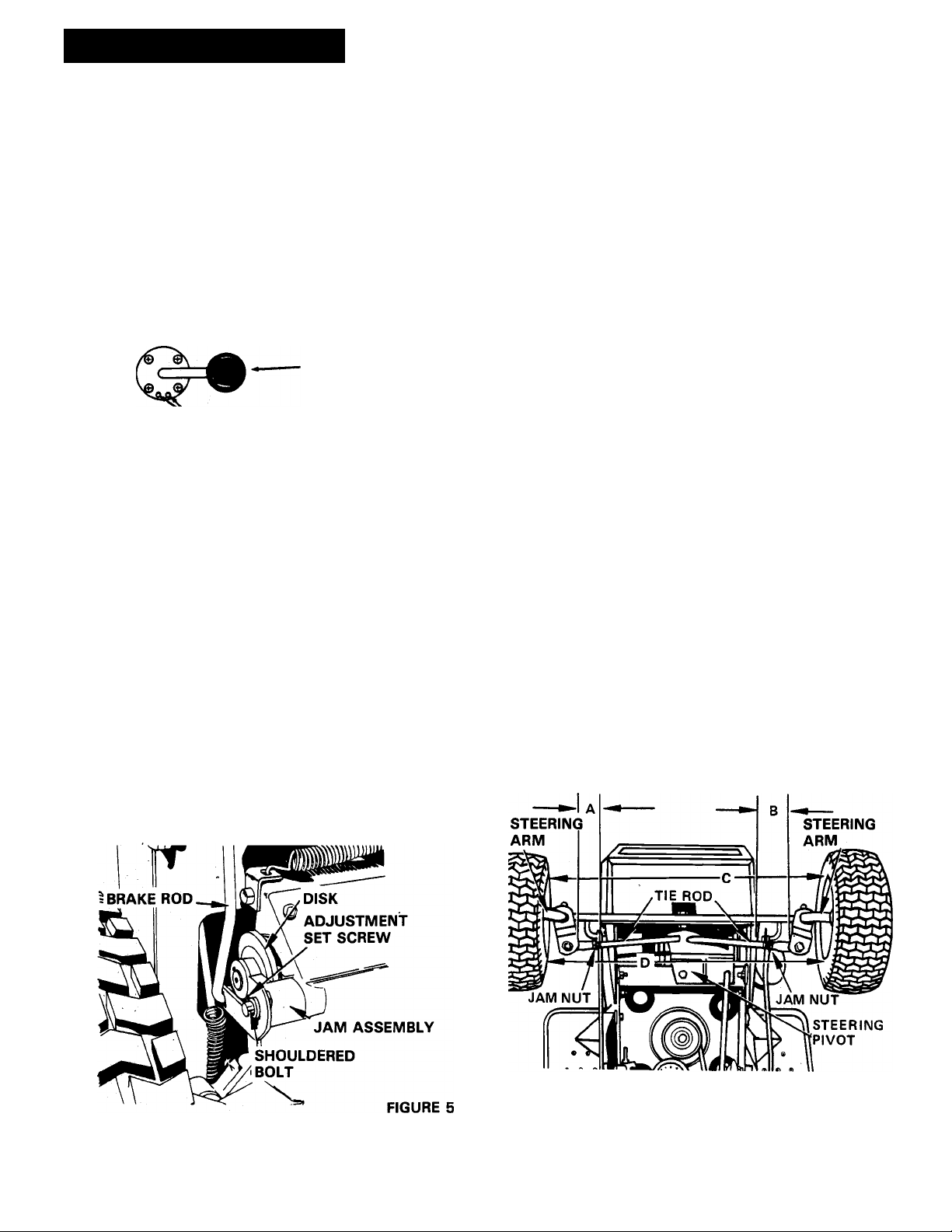
DISK BRAKE ADJUSTMENT - FIGURE 5
Once each season, or if the brake begins to slip and
does not hold the tractor, it is necessary to adjust the
disk brake located on the lower left side of the transaxle
assembly. See Figure 5. Adjust as follows:
1. Position the tractor on a smooth level surface and
place the speed selector lever in “NEUTRAL" so
the tractor can be pushed by hand to check the
brake.
2. Adjust the setscrew in the brake jaw assembly
clockwise until the brake just starts to lock. This
can be felt by pushing the tractor by hand. Leave
the brake pedal up during this adjustment.
The tension on the brake pedal itself is adjustable. If the
brake pedal does not return or feels loose, adjust the
nut on the end of the brake rod just inside the frame
next to the parking brake slot. Tighten the nut until the
spring adjacent to the nuts is 1 % inches in length.
FRONT WHEEL TOE-IN ADJUSTMENT - FIGURE 6
Proper toe-in of the front wheel is necessary to assure
proper steering and to reduce tire wear. Correct toe-in
is when the front of the wheels are Vs" to Vi" closer
together than the rear of the wheels (measured at the
horizontal center line of the rim flanges).
If the steering develops a wandering characteristic or if
excessive tire wear develops, the toe-in of the front
wheels should be checked. If the toe-in is not correct,
adjust as follows;
1. Turn steering wheel until the rear edge of the
steering pivot is perpendicular (90 degrees) to the
tractor frame as shown in Figure 6.
2. Adjust length of tie rods until distances from
steering arm to frame (A and B) are equal and so
distance C is between Vs" to Vi" less than
distance D.
NOTE: USE FOLLOWING PROCEDURE TO SHORTEN
OR LENGTHEN TIE RODS.
1. Loosen jam nuts on ends of tie rods. Figure 6.
2. Remove the locknuts and pull out the ball joints.
Rotate tie rods until distances A and B, Figure 6,
are equal and distance C is Vs" to Vi" less than D.
3. Tighten jam nuts securely. Replace ball joints in
holes and secure with locknuts.
Turn setscrew Vi turn counterclockwise
locking point to adjust the brake.
from
FIGURE 6
-7-
Page 8

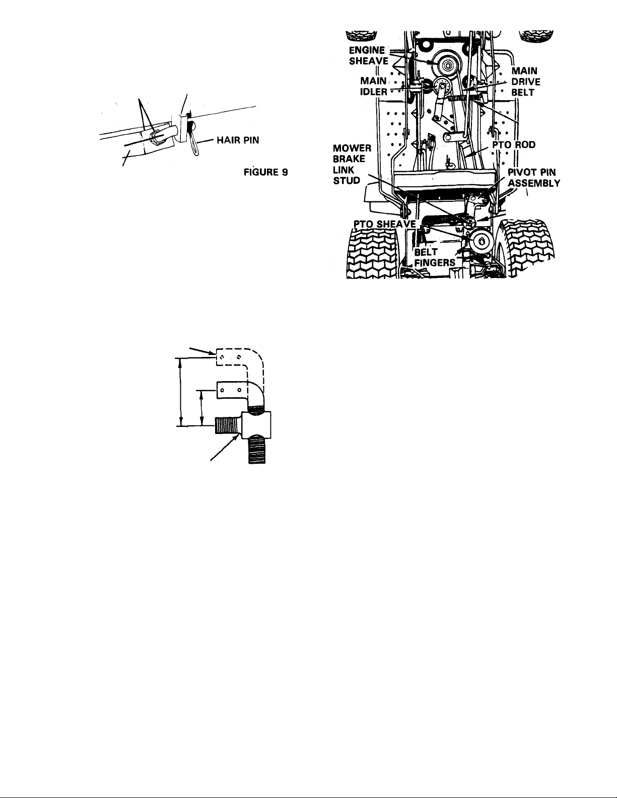
REMOVAL OF MOWER PAN - FIGURES 7 & 9
In order to perform some maintenance it may be
necessary to remove the mower pan as follows:
1. Lower the mower pan. Remove the hairpin cotter
and washer from the stud on the attachment idler
(Figure 9) and disconnect the mower brake link.
2. Raise the mower deck. Loosen the belt fingers on
the tractor PTO sheave, slide them to one side,
and remove the mower belt from this sheave. See
Figure 9.
3. Lower the mower pan and remove the hairpin
cotters and washers. The two pins and washers
on the front secure the mower pan to the front
hangers and can be disconnected to free the front
of the pan. The other two pins and washers join
the front of the pan to the belt tightener bracket.
Loosen the hex nuts and turn the rear hanger
hooks to the side to free them from the rear
hangers. See Figure 7.
4. Place front hanger on top of rear hanger. Raise the
Attachment Lift Lever to pull the hangers up out
of the way. Pull the mower pan from under the
tractor.
The front and rear hangers may be assembled and
engaged with washers and hairpin cotters.
3. Lower the Attachment Lift Lever. Slide the pan
back (while lifting the rear of the pan) so that thé
pan hanger hooks slide up on the rear hanger.
Assemble the front hangers to the tabs on
mower pan, while, at the same time, assemb'
the front and rear hangers. Secure with fo^i
washers and hairpin cotters. Connect the Belt
Tightener Bracket to the pan.
4. Raise the Attachment Lift Lever to maximum
height. Connect the Mower Belt to the tractor
PTO Sheave.
5. Connect the blade brake arm to the stud on the
center of the Attachment Clutch Idler. Secure
with a washer and a hairpin cotter.
6. Adjust the belt fingers on the tractor PTO Sheave
to clear the belt by 1 /8 to 1 /1 6”. Tighten the belt
finger hardware.
INSTALL BLADE BRAKE ARM AS SHOWN
35261 BRACKET
32235 (32” MOWER) 73108
35248 (38” MOWER)
64093 WASHER
67020 HAIRPIN
IDLER
64093 WASHER /
67020 HAIRPIN
NUT
FIGURE 8
CLEVIS PIN
REAR BRACKET
REAR HANGER HOOK'^^^-^ RRAPkPT
INSTALLATION OF MOWER PAN - FIGURES 7 & 8
Position the tractor on a smooth, level surface and in
stall the mower pan as follows:
1. Lower the Attachment Lift LeVer. One front set of
pins and washers will connect the tabs on the
front of the mower pan to the front hangers, the
second set of pins and washers connect the front
of the pan to the belt tightener bracket. The rear
set of pins and washers connect the rear hangers
to the frame.
HAIR PINS &.
WASHERS BELT*
FRONT HANGER
TIGHTENER
FIGURE 7
MOWER PAN LEVELING - FIGURES 7, 9 &13
The mower pan is designed to cut evenly with the rear
of the pan 1/8 inch higher than the front. To level the
mower pan proceed as follows:
1. Position the tractor on a smooth, level surface.
Adjust tire pressure as follows (light loading):
Front - 10 psi / Rear - 6 psi
2. Measure the distance from surface to mower
blades at the front and rear of the pan. The rear of
blades should be 1/8 inch higher than front and
blades should hang even side to side.
3. If adjustment is required, turn the hex nuts on the
rear hanger hooks to mo\/e the hooks up or down
to secure the proper adjustment. When the pan is
leveled and hangs evenly, tighten the hex nuts
securely. See Figure 7.
4. Adjust mower belt for proper center distance. See
Figure 9 and 13. Adjust nuts on the adjustor rod
to move mower pan forward or backward. Adjust
1 to 1 'h inch clearance between belt as shown in
Figure 13 with mower pan in highest position.
2. With the Mower Belt in place on the pan and the
lift arm in its highest position, position the pan
under the tractor and forward against the front
wheels.
CAUTION: ADJUSTMENT TOO FAR FORWARD W,.^
NOT ALLOW MOWER BELT TO DECLUTCHI CHECK
FOR PROPER MOWER BELT DECLUTCHING IN ALL
HEIGHT POSITIONS. IF MOWER BELT DOES NOT
-8-
Page 9
DECLUTCH, ADJUST MOWER PAN BACKWARD UN
TIL PROPER DECLUTCHING OCCURS. (P.T.O.
SHEAVE MUST NOT HAVE A TENDENCY TO DRIVE
MOWER BELT AND/OR OVERRIDE BRAKE.)
MOUNTING POST
ADJUSTMENT NUTS
ADJUSTOR ROD
BELT TIGHTENER BRACKET
ON FRONT AXLE
MAIN IDLER
SPRING
MOWER PAN CUTTING HEIGHT - FIGURE 10
After the mower pan has been leveled properly, minor
adjustments can be made in the pan cutting height by
increasing or decreasing the center distance between
35321 rod end and 35322 adjustment link. Increasing
center distance lowers cutting height. Decreasing
center distance raises cutting height. Raising the At
tachment Lift Lever to another notch in the lift quadrant
will also raise the cutting height of the mower pan. Ad
just to suit individual grass cutting conditions.
35322
ADJUSTMENT LINK
THIS DISTANCE
CHANGES CUTTING
HEIGHT
35321 ROD END
FIGURE 10
DRIVE BELT REPLACEMENT - FIGURES 11 & 12
ATTACHMENT
IDLER & ARM
FIGURE 11
7. Remove hair pin and Mower Brake Link from
Attachment Idler. See Figure 11.
8. Disconnect Attachment Idler spring from an
chor on right side of transaxle. (Use vise
grips). See Figure 11.
9. Remove cotter pin, washer and PTO Rod
from the Attachment idler arm. Figure 11.
10. Loosen fasteners holding two belt fingers
around Traction Drive Belt to frame, and
rotate fingers away from belt. See Figure 1 2.
11. Depress Clutch Pedal with left foot and un
wrap Traction Drive Belt from transaxle and
upper groove of top PTO Sheave. Figure 1 2.
A. Removal of Worn Belt
NOTE: REMOVE SPARK PLUG WIRE.
1. Loosen fasteners holding two belt fingers
near PTO Sheave and rotate fingers away
from sheave. See Figure 11.
2. Move Implement Clutch Lever to "OUT”.
3. Raise mower to highest position with At
tachment Lift Lever..
4. Unwrap mower drive belt from PTO Sheave
(DO NOT PRY).
5. Lower mower to lowest position with At
tachment Lift Lever.
6. Move Implement Clutch Lever to "IN”.
12. Release clutch, disconnect traction clutch
spring from Traction Clutch Idler Arm. (Use
vise grips). See Figure 12.
13. Rotate Attachment Idler until hair pin at top
of idler assembly pivot pin can be removed
rearward. See Figure 12.
14. Remove PTO pivot pin, hair pin and washer.
Figure 1 2.
1 5. Lower Attachment Idler assembly until Trac
tion Clutch Idler Arm is free of pivot pin.
16. Disconnect Main Idler spring from anchor
point at left side of frame. (Use vise grips).
17. With a ®/ie” open end wrench, hold the
jackshaft via the milled flats under the PTO
Sheave. Remove large nut and internal tooth
lockwasher on top of jackshaft. Figure 1 2.
-9-
Page 10

T8. Slide or drive, if necessary, “the jackshaft
downward until it clears the top PTO
Sheave. If the shaft must be driven use a %
or ®/g” diameter punch so as not to flatten
the top threads.
19. With the top PTO Sheave clear of the
jackshaft the Main Drive Belt can be un
wrapped.
20. Slide rear of belt ahead and between upper
traction and lower Attachment Idler
assemblies. See Figure 11.
14. Grasp Traction Clutch Idler spring with vise
grips and connect hook to Traction Clutch
Idier Arm. See Figure 12.
1 5. Depress traction clutch pedal and wrap Trac
tion Drive Belt around upper groove on PTO
Sheave and Transaxle Sheave. DO NOT
PRY. See Figure 12.
16. Release Clutch Pedal and align and tighten
traction belt fingers to Vie” to Ve” from belt.
17. Move Implement Clutch Lever to "OUT”.
21. Unwrap main belt from Engine Sheave and
remove from tractor.
B. Installation of New Belt
1. Wrap new main belt around Engine Sheave.
2. Feed other end rearward, above steering arm
and through, between upper Traction and
lower Attachment Idler pivot assemblies.
3. Push Attachment Idler arm upward until
pivot pin is completely positioned through
the traction clutch idler arm pivot.
4. Rotate Attachment Idler Arm so that hair pin
can be reinstalled in a forward direction.
Place washer over pivot pin and install hair
pin.
5. Move Implement Clutch to "IN”.
6. Feed PTO Rod between Main Drive Belt
lengths and install end through hole in At
tachment Idler Arm. See Figure 11.
7. Install washer and cotter pin in PTO Rod.
18. Raise Attachment Lift Lever to highest posi
tion.
19. Wrap Mower Belt around bottom PTO
Sheave. DO NOT PRY.
20. Re-align fingers around bottom PTO Sheave •
pulley Vie” to Vg” away from pulley and
tighten.
21. Move Implement Clutch Lever to "IN” posi
tion.
22. Attach Mower Brake Link to Stud under At
tachment Idler and secure with hair pin. See
Figure 8.
23. Leave spark plug wire disconnected.
24. Lower Attachment Lift Lever to lowest posi
tion.
25. Move Implement Clutch Lever to "OUT”.
Place Speed Selector Lever in "NEUTRAL".
26. Crank engine with starter about six revolu
tions.
8. Connect Attachment Idler spring to anchor
on right front corner of transaxle. (Use vise
grips).
9. Wrap main belt around lower (larger) groove
of top PTO Sheave. See Figure 1 2.
10. Align top PTO Sheave bore above jackshaft
spindle bore and slide jackshaft upward and
through top PTO Sheave. Be sure spacer
washer is between upper spiindie bearing and
top PTO Sheave. See Figure 12.
11. Insert key in PTO jackshaft and top PTO
Sheave assembly.
12. Install internal tooth lockwasher on top’of
jackshaft and secure assembly with nut. Use
flats on bottom of jackshaft to hold'.
1 3. Reconnect Main Idler Spring to anchor hole
on left side of frame. Be sure Main Idler is on
backside of Main Drive Belt and spring is
above steering link. See Figure 11.
-10-
27. Inspect Main Drive Belt and Main Idler for
alignment and clearance from sharp edges.
28. Replace spark plug wire and test function.
TRACTION
MAIN CLUTCH
DRIVE 'CLE”
BELT
35026 I
CAM TRACTION
ACTUATOR
IDLER
1 1
TRACTION DRIVE BELT
TRANSAXLE
SHEAVE
■ 1
BELT
FINGER
FIGURE 12
Page 11
REPUCEMENT OF TRACTION DRIVE BELT • FIGURE 12
The Traction Drive Belt is easily replaced by lifting the
rear deck; loosening the belt fingers; including belt
finger on Traction Clutch Idler Arm; depressing the
Clutch Pedal and removing the belt. Replacement is
similar, depress the Clutch Pedal; install the belt and
replace the belt fingers. Adjust the three belt fingers to
provide Vi to Vie inch clearance from the belt with
clutch engaged (pedal up).
MOWER BELT - FIGURES 13 & 14
If belt squeals when Implement Power Clutch is proper
ly engaged, check adjustment of belt. If squeals con
tinue, belt may require replacement.
A. Removal
1. Place the Attachment Lift Lever in the lowest
position, (forward). Disengage the Attach
ment Clutch (lever to rear).
strength and stability. This assures that the belts will
deliver maximum performance and durability for each
product's specific applications.
The selling price of ARIENS BELTS reflects these quali
ty features. Our name and number stamped on your
replacement belt is your assurance of receiving the
quality you are paying for.
TOP VIEW
P.T.O.
31755 BELT FINGERS
ATTACHMENT IDLER ICLUTCHINQI
MOWER SHEAVE
P.T.O. SHEAVE
BELT CLEARANCE:
MAX. IN HIGHEST
POSITION; 1" MIN. IN
LOWEST POSITION.
MOWER BELT
FIGURE 14
2. Loosen the belt fingers at the PTO Sheave
and turn them away from the sheave.
3. Remove the hair pin or cotter pin securing
the brake band and rotate the band away
from the sheave. See Figure 13.
HAIR PIN
32" MOWER
ONLY
ADJUST FOR 1-1/8"
SPRING LENGTH
MOWER SHEAVE
38" MOWER ONLY
- HAIRPIN FIGURE 13
4. Raise the mower pan to its mid position and
remove the Mower Belt from the PTO
Sheave; lower the pan and remove the belt
from mower pan. See Figure 14.
B. Replacement
1. Position the replacement Mower Belt around
the sheave on the mower pan. Reposition
the brake band around the sheave and
secure with the cotter or hair pin. See Figure
13.
2. Raise the mower pan to its center position
and install the Mower Belt around the PTO
Sheave. See Figure 14.
A NOTE ABOUT ARIENS BELTS
MOWER BRAKE ADJUSTMENT - FIGURE 13
With the Mower Belt adjusted and the Implement
Power Clutch disengaged, adjust the nut on the end of
the brake rod until the spring is 1 Vs" in length. See
FIgur« 13.
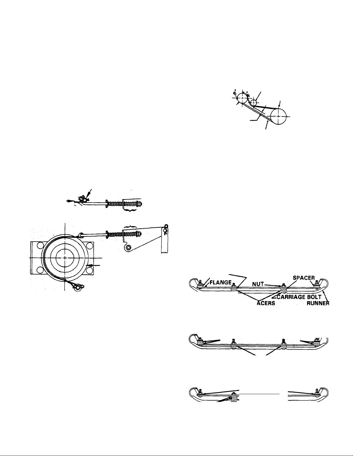
MOWER RUNNER ADJUSTMENT
After adjusting the cutting height and blade pitch as
described elsewhere In this section, thè mower runners
may be adjusted, as desired, to allow smooth, even
cutting of grass at different cutting height settings. Ad
justment must be even from side to side. Assemble out
side spacers to runners and mower before center
spacers. This will aid in alignment and ease of installa
tion. Do not tighten hardware until outside spacers are
installed.
1. To pre-set the runners prior to a test cutting they
may be adjusted as shown in Figure 1 5.
SPACER
CARRIAGE BOL^
6071 SP
FIGURE 15
2. To obtain smoothest cutting in lowest cutting
height settings, the runners may be adjusted as
shown in Figure 1 6.
2 SPACERS 2 SPACERS
6071 SPACERS
FIGURE 16
To obtain smoothest cutting in higher cutting
height settings, the runners should be adjusted as
shown in Figure 1 7.
-NO SPACERS-Tc-
ARIENS BELTS are individually engineered to the
highest standards of material quality, design, and con
struction including special cording locations for
2 SPACERS
2 SPACERS
'6071 SPACER
Flfsi"-
Page 12
MAIIMTEIMAIMCE
CAUTION; REMOVE BATTERY FROM TRACTOR
BEFORE TIPPING OR LIFTING THE UNIT FOR AD
JUSTMENTS. BATTERY IS NOT SEALED AND SPILLED
ACID WILL DAMAGE PRODUCT. WHEN HANDLING
BATTERY BE SURE TO AVOID CONTACT WITH BAT
TERY ACID, WHICH CAN CAUSE SERIOUS INJURY TO
EYES, ETC. FOLLOW ALL CHARGING INSTRUCTIONS
CAREFULLY. WHEN "JUMP STARTING" THE UNIT BE
SURE TO CONNECT THE NEGATIVE BOOSTER CABLE
TO FRAMES (NOT TERMINAL.)
GENERAL
All dealers will provide any service which may be re
quired to keep the Yard Tractor operating at peak effi
ciency. Ariens Company recommends that you contact
an Ariens dealer before making any adjustments to this
tractor. Refer to the Engine Instructions for engine
maintenance instructions. If repairs or service are re
quired for the engine, see your Ariens dealer or the
nearest authorized engine service station.
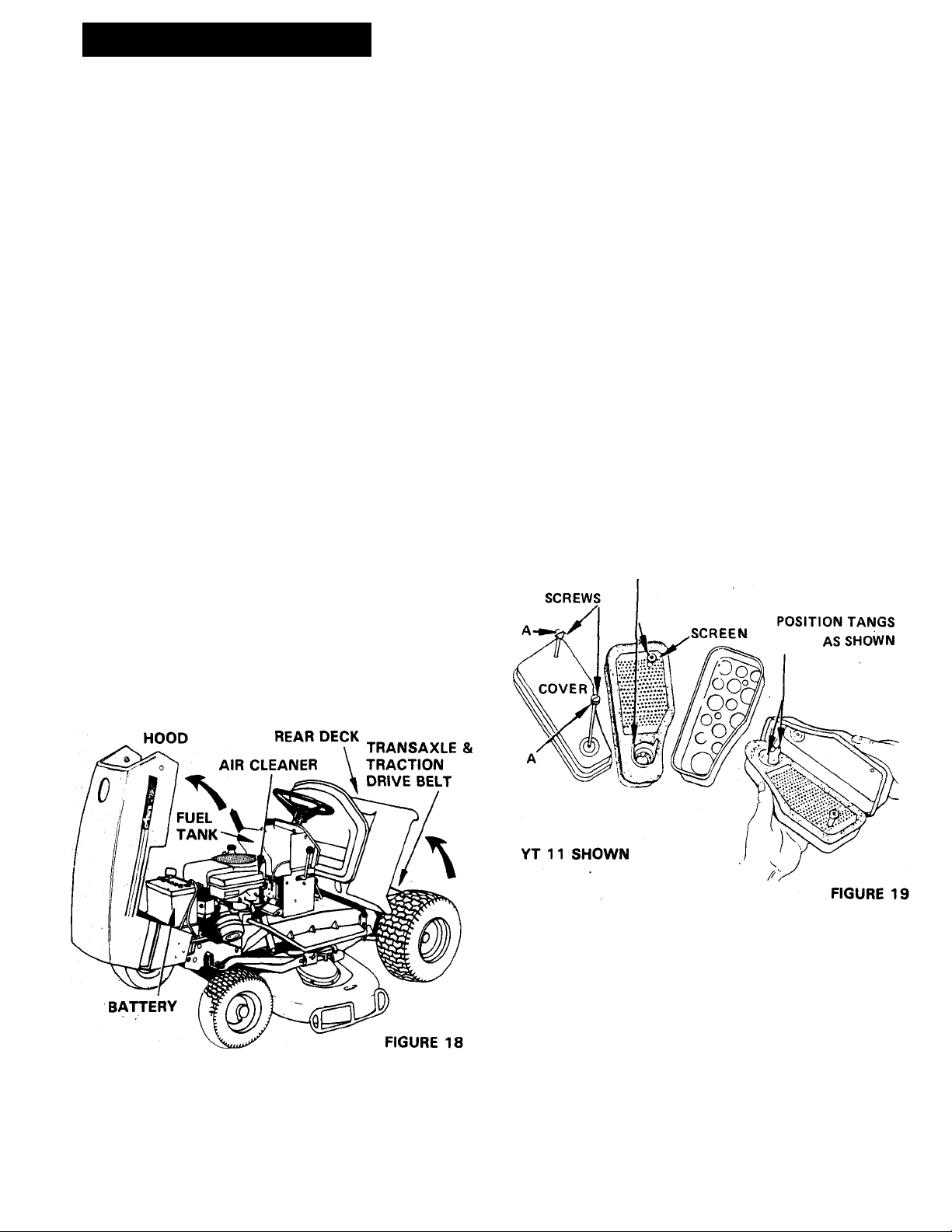
RAISING THE HOOD - FIGURE 18
1. The engine, battery, electrical components, air
cleaner, fuel filter and fuel tank are readily ac
cessible by raising the hood.
operating in extremely dusty conditions, perform thi<^^
service at more frequent intervals. Use the followinv
procedure to service the air cleaner.
1. Raise the tractor hood. Remove screws, "A", Figure
1 5, and lift off complete air cleaner assembly.
2. Remove screen and spacers from the foam ele
ment, Figure 1 9.
3. Wash foam element in kerosene or liquid
detergent and water to remove dirt. Wrap foam in
cloth and squeeze dry. Let dry overnight.
4. Saturate foam element in clean oil. Squeeze to
remove the excess oil.
5. Re-assemble parts and re-install complete
assembly on the carburetor.
NOTE: WHEN RE-ASSEMBLING THE PARTS, MAKE
CERTAIN THE FOAM ELEMENT EXTENDS OVER THE
EDGE OF THE AIR CLEANER BODY. THE FOAM ELE
MENT WILL FORM A PROTECTIVE SEAL.
IMPORTANT: NEVER RUN THE ENGINE WITH THE AIR
CLEANER REMOVED!
2. To raise the hood, grasp each side and raise it up
wards and forward until it stops.
RAISING THE REAR DECK - FIGURE 18
The trahsaxle, PTO and jackshaft assembly, clutch
idler, and Traction Drive Belt are readily accessible by
raising the rear deck until the seat rests against the
steering wheel.
LIFT UP
LIFT UP
SPACERS
ENGINE COOLING SYSTEM - FIGURE 20
1. The engine is air cooled. Grass particles, chaff and
dirt may clog the cooling systehi, especially when
mowing dry grass or operating in extremely dusty
conditions. Continued operation with a clogged
cooling system may cause severe overheating and
possible engine damage. ^
AIR CLEANER SERVICE - FIGURE 19
Clean the air cleaner and re-oil the element every 25
hours under normal operating conditions. When
2. It is essential that the rotating screen, engine cool
ing fins and the exhaust system be kept free of
dirt and debris which could cause the engine to
overheat.
- 12
Page 13

To avoid overheating and possible engine
damage, periodically remove the shrouding from
around the cooling fins. Figure 16, and clean the
area shown within the heavy black line of all
grass,dirt or chaff accumulation.
KEEP AREAS WITHIN
HEAVY LINES CLEAR
OF ALL DEBRIS
TIRES PRESSURES - TABLE 1
Check tires pressures at least once each month. Inflate
tires to pressures shown using a low pressure tire
gauge for accurate readings. Keep tires properly in
flated at all times. Over-inflation will cause operator
discomfort. Under-inflation will cause short tire life.
Make sure the tire valve caps are in place.
TIRE SIZE
Ught
LOADING
Medium
Heavy
FIGURE 20
SEAT MAINTENANCE
Clean the seat regularly, using a vinyl cleaner (not a sol
vent.) Extreme temperatures can damage the seat
when left without protection against the weather. If the
seat should tear, apply vihyl repair tape to the damaged
area.
BATTERY SERVICE
NOTE: REFER TO "BATTERY SET-UP AND
MAINTENANCE” SECTION, PAGE 36.
1. Check the battery electrolyte level once each
week or every 25 hours of operation. Check it
monthly if the tractor is idle or is in storage. Add
distilled water to bring the level to the bottom of
the split ring in the filler tube of each cell.
2. Each spring and fall clean the battery and ter
minals with ammonia or bicarbonate of soda solu
tion followed by flushing with clean water. Keep
ing the battery clean will prolong battery life.
After cleaning, apply a light coat of grease to the
terminal and cable ends.
3. Keep cable clamps securely tightened to terminals
and keep battery hold-down clamps tight to pre
vent vibration. Do not overtighten clamps. This
could warp the case.
WARNING; STORAGE BATTERIES GIVE OFF HIGHLY
INFLAMMABLE HYDROGEN GAS. DO NOT ALLOW
SPARKS OR FLAME NEAR BATTERY. DO NOT LAY
TOOLS ACROSS BATTERY TERMINALS WHICH MAY
CAUSE A SPARK RESULTING IN AN EXPLOSION.
Front
13 X 5.00 - 6
Rear
18 X 8.50 - 8
(Lawn Work) (Sno-Thro)
8 psi 12 psi
(Lawn Work)
6 psi
(Sno-Thro)
8 psi
16 psi
10 psi
TABLE 1
FUEL FILTER SERVICE - IFIGURE 21
Wheri dirt or other foreign material is allowed to enter
the fubi tank it will collect in the fuel filter eventually
causing fuel stoppage. If this occufs, replace filter.
MOWER BLADE AND VANES MAINTENANCE
Check tire pressure. Uneven tire pressure may cause
uneven grass cutting.
Models with 32” mowers are equipped with high lift
blades standard. Vanes (Service Part No. 527011)
may be bolted to the blades to improve discharge and
bagging or collecting of grass. These vanes may or may
not be helpful depending on your type of grass and
cutting conditions.
Ariens recommends that the user try the mower
without vanes first and if the performance is satisfac
tory, use without vanes since the vanes use more
power and generate more noise. Use vanes (Service
Part No. 52701 1) only if satisfactory performance can
not be obtained without them. Generally, broadleaf
grasses can be cut and bagged without vanes. The
finer grasses may require vanes. In extremely wet con
ditions, vanes may also be of help.
Routinely check for wear on the mower blade and
vanes, if used. This is especially true in sandy soil con
ditions.
4. Maintain the battery at full charge during storage
and during the winter months to prevent freezing.
When water is added during freezing weather, run
the engine at least on hour to bring the battery up
to a full state of charge.
5. When installing the battery, make certain the
ground cable is connected to the negative(-) ter
minal on battery. See Figure 22. Be sure positive
cable is connected to positive {+) terminal.
CAUTION: WEAR OF THE MOWER BLADE CAN
CAUSE STRUCTURAL WEAKNESS. DO NOT INSTALL
NEW OR REPLACEMENT VANES ON WORN BLADES.
THIS IS A POTENTIAL HAZARD.
Replace worn parts with Ariens original equipment,
blades, vanes, and Grade 8 hardware as specified. Cap
screws must be installed with heads on top of the
vanes and vanes on top of the blade.
13 -
Page 14

NOTE; CAPSCREWS MUST BE
LOCATED ON TOP OF VANES
AS SHOWN.
NOTE: MOUNT VANt
TO BLADE As
SHOWN ONLY
WITH WORD
"FRONT"
EXPOSED
IMPORTANT: THE VANES (SERVICE PART NO.
527011) MUST BE USED IN PAIRS. THEY CANNOT
BE INTERCHANGED WITH Dlf^FERENT OR WORN
VANES ON THÉ SAME BUDE. USING ON| OF EACH
OF A DIFFERENT TYPE OR WORN VANE WILL CAUSE
THE BLADE TO BE OUT OF BALANCE AND SEVERE
VIBRATION WILL OCCUR. EVEN WEAR ON THE
PARTS AND PROPER BALANCE IS ENSURED BY
REPLACING VANESPAIRS.
GRADE 8
CAPSCREWS
VANE
LOCKNUTS
FIGURE 22
protection while removing mower blade. Remove the
nyt and lockwasher- securing the blade and remove *
blade. See Figure 23.
Sharpen, blade by following the same contour of the’
cutting edge; be careful not to rourvd off the outer cor
ners of cutting edge.
Sharpen both cutting edges fqpally to,<keep the blade
balanced.
The mower blade should always be kept sharp and pro
perly balanced. Disconnect spark plyg wire. Remove
Mower Pan, clear dirt and grass from underside, and
check blade. Use a heavy glove or padding for hand
Replace mower blade In position oh mower and secure
with lockwasher and nut. Torque to 50-55 lbs. Be sur^-.^
to use a heavy gloye or padding for hand protectio 1
while fastening blade.
-14 -
Page 15

FILLING THE FUEL TANK - FIGURE 24
Before filling the tank, wipe all dust and dirt from
around the cap to prevent dirt from falling into the tank.
Use an approved gasoline container and keep it clean.
Fill tank completely. The tank capacity is 1.7 gallons
(6.5 liters). Use clean, fresh "regular” grade of
automotive gasoline. Use leaded or unleaded type. Do
not use premium gasoline. Do not mix oil with gasoline.
Refer to Engine Instructions also.
DANGER: ALWAYS USE CAUTION WHEN HANDLING
GASOLINE. NEVER FILL THE FUEL TANK WHEN THE
ENGINE IS RUNNING OR WHEN THE ENGINE IS HOT.
NEVER SMOKE WHILE FILLING THE TANK. REMOVE
THE IGNITION KEY BEFORE FILLING TANK.
ENGINE OIL - FIGURE 24
Fill crankcase with oil as recommended below. Refer,
also, to Engine Manufacturer's Instructions supplied
with the product. Check oil level before each use and
change oil regularly according to Engine.
Manufacturer's Instructions. Check oil level with trac
tor on a level surface. Keep dipstick area clean.
IMPORTANT: ENGINE WILL SMOKE EXCESSIVELY IF
DIPSTICK IS NOT PUSHED DOWN UNTIL IT SNAPS IN
TO PLACE.
CHANGE ENGINE CRANKCASE OIL
1. When the tractor is new, the oil should be chang
ed after the first five hours of operation.
Thereafter under normal operating conditions the
oil should be changed every 25 hours of opera
tion. If extremely dusty or dirty conditions prevail,
change oil more frequently.
2. Drain crankcase by opening petcock or removing
the drain plug. Figure 24, while the engine is
warm. Allow the oil to run into a container.
NOTE: WITH THE ENGINE WARM, THE OIL WILL
FLOW MORE FREELY PERMITTING MORE CON
TAMINANTS TO BE DRAINED FROM THE
CRANKCASE.
3. Close petcock or replace the drain plug. Remove
dipstick and refill crankcase with the proper type
and viscosity of oil as shown in Tables 2 & 3.
Check oil on the dipstick to make sure that the
level is to the "FULL" mark. DO NOT OVERFILL.
■MJ
•Sjl
SEASON
Summer:
(Above 32°F)
Winter:
(Below 32°F)
ENGINE CRANKCASE CAPACITY IS 2 PINTS. DO NOT
OVERFILL.
SEASON ENQINE OIL RECOMMENDA
Summer:
(Above 32°F)
Winter:
(Below 32°F)
Below 0°F:
ENGINE OIL RECOMMENDA
TIONS - YT8
SAE SOW or substitutes:
SAE 10W30, 10W40
SAE 5W30 or substitute:
SAE 10W
TABLE 2
TIONS - YT11
SAE SOW or substitutes:
SAE 10W30, 10W40
SAE 10W30, 10W40
SAE 5W20, 5W30; or
substitutes: 5W20, 5W30,
5W40 synthetic oil
STEERING GEARS - FIGURE 24
Apply a light coat of Ariens Moly Lithium grease to
steering gears every 50 hours of operation. See Figure
24.
ENGINE CRANKCASE CAPACITY IS 3 PINTS (1.4
LITERS). DO NOT OVERFILL.
TABLE 3
TRANSAXLE OIL LEVEL
The Transaxle is lubricated at the factory and should re
quire no further lubrication by the owner.
- 15 -
Page 16

LUBRICATION
GREASE FITTINGS
Each fitting should be wiped clean before and aft
lubrication. Grease each fitting every 50 hours of
operation with Ariens Moly Lithium grease. Following is
a list of the grease fittings with reference numbers that
identify each location on the corresponding illustra
tions.
1. Right and Left Steering King Pins — Figure 25.
2. Right and Left Front Wheels — Figure 25.
3. Jackshaft Spindle Housing — Figures 25 & 27.
4. Grease mower input (center) spindle.
5. Transaxle is sealed for dirt-free operation.
However, should repairs be needed, requiring ad
ditional lubrication, use Ariens Moly Lithium
Grease, Part No. 1 50.
FIGURE 25
JACKSHAFT
SPINDLE
HOUSING
TRACTION DRIVE BELT O
o
POINTS TO OIL - FIGURES 25, 26 & 27
1. Periodically oil the lift point pivots, front axle
pivot, control linkage pivots and the shaft pivots
to insure long life and smooth operation of the
parts. See Figures 25 and 27.
2. Lubricate slide for shift interlock switch. See
Figure 26.
IMPORTANT; KEEP GREASE AND OIL OFF THE BELTS
TO AVOID BELT SLIPPAGE AND DETERIORATION.
CTi !r~] LJ
o
FIGURE 27
- 16
Page 17

STORAGE
NOTE; THESE INSTRUCTIONS WILL ASSIST YOU IN
PREPARATION BEFORE AND AFTER STORAGE.
ENGINE
NEVER STORE PRODUCT IN AN ENCLOSED AREA
WHERE FUEL FUMES MAY REACH AN OPEN FLAME,
SPARK, OR PILOT OF FURNACE, ETC. DRAIN FUEL
OUTDOORS, AWAY FROM OPEN FLAME, AND USE
ONLY AN APPROVED FUEL CONTAINER.
If product is not to be used for thirty days or more,
prepare as follows:
1. Run engine until fuel tank is empty and engine
stops due to lack of fuel.
2. Be sure all fuel is removed from fuel tank (as well
as any contamination). The carburetor and fuel
tank must be clean and dry to prevent gum
deposits from forming and the engine from
malfunctioning.
3. If gasahol has been used, complete the steps
above, then put a small amount of regular gasoline
into the fuel tank and repeat the steps.
4. Remove all oil, grease, dirt and debris from the
engine.
8. Recap the spark plug according to Engine Instruc
tions supplied with your tractor. Replace the spark
plug if required.
BATTERY
Refer to "Battery Set-Up and Maintenance", page 36
of this manual.
GENERAL
NOTE: YOUR AUTHORIZED ARIENS DEALER IS
TRAINED AND EQUIPPED TO SERVICE YOUR TRAC
TOR. A PERIODIC CHECK-UP BY YOUR DEALER WILL
HELP REDUCE YOUR MAINTENANCE COSTS.
Store product in a cool, dry place to reduce tire
deterioration. Blocking under the product frame will
take the weight off the tires.
Inspect product for visible signs of wear, breakage or
damage. Order any parts required and make necessary
repairs to avoid delays when beginning use again. Your
Ariens dealer will be able to assist you.
Clean the product thoroughly.. Touch up all scratched
and exposed areas with paint to avoid rust. Your Ariens
dealer stocks the following aerosol paints:
5. Change the engine oil. See "LUBRICATION" sec
tion of this manual.
6. Check and, if necessary, clean the air cleaner and
replace fuel filter.
7. For extra protection remove the spark plug and
pour one tablespoonful of engine crankcase type
oil into the cylinder. Turn engine over manually
(two revolutions of crankshaft).
Ariens Charcoal Brown
Ariens Sunset Orange
Ariens White
NOTE: ARIENS RECOMMENDS USING A HIGH QUALI
TY PRIMER AS A BASE FOR THE TOUCH UP PAINT.
THE TOUCH UP PAINT WILL NOT PROVIDE THE HIGH
GLOSS FINISH OF ORIGINAL BAKED-ON PAINT. COL
OR MAY VARY SLIGHTLY, ALSO.
Part No. 64
Part No. 65
Part No. 66
- 17 -
Page 18

FRAME/CHÂSSIS
935003, 935004 & 935005
. '"’ií
■ 1
Jâ)
•H®
18-
Page 19

r
FRÂME/CHÂSSIS
935003/935004 & 935005
Node N0 DECODE
REF. PIEC^ D'INV
REF. PART STOCK
NO. NO. CODE
1
535028
2
063004
3
065018 M Nut, 3/8-16 UNO 26
5
059135 M
6 063003 M Lockwasher, STO 5/16"
7
065015
8
035006 0 Strut Right Foot Board
9 035007
10
062011
16
035043 F Idler Arm
17 035044
18 055036
19
064043 M Washer, 3/8" STO x 13/16 x .065 PL
20
067004
21
035038 0
22 075054
23 035039
24
035040
25 035041
26 064002 M
27
006071 M
29 075026
31 535026
31 535027
32
029206
064007
33
34
063002 M Lockwasher, STO 1/4" 14
35 065032 M Nut, 1/4-20 UNC 14
36 031149 F Headlight 2
0 Main Frame W/Oecals
M Lockwasher, STO. 3/8"
M
0 Strut Left Foot Board
M
S
F Flange Bushing
M "Cotter Pin, 1/8x1
M Bumper
S Seat Channel R.H.
S Seat Channel L.H.
M Seat
M Grommet
s
s
s
M
DESCRIPTION
Cap Screw, 5/16-18 x 3/4. 14
Nut, 5/16-16
Carriage Bolt, 5/16-18 x 5/8
Idler Pivot
Rear Osck
Washer, STO 5/16 x 7/8 x .083 PL
Spacer Bushing
Hood 8i Grill W/Decals, YT8
Hood 8i Grill W/Oecals, YT11
Headlight Insert 1
Washer, Std. 1/4 x 47/64 x .065 PL 14
QUANTITÉ
NO. REQ'D
Node No DE
REF. PIECE
REF. PART
NO. NO.
1
8
3
40
17 41
15 42
1
43
1. 44
4
45
1 46
1
2
1
47
1
48
1
49 073111
2 50
1 51
1 52
1 53
54
6
2 56
58
1
60 083058
1
61
1
62
63 031904
64
65 065039
66 030055
67
68 064117 M
CODE
D'INV.
STOCK
CODE
37
031159
38
061045 M
39
065095
075058 M Stop
029122
061041
035050 0 Cash Biise
062011
059022
631006 S
061040 M Machine Screw, 10-24 x PL
059161
063011
065055 M Nut
031716
029131
065096 M Nut
062013
029123
064008 M Washer, STO 3/8"
063032
065098
069110 M Clip
S Headlight Retainer Ring
M
M Hood Hinge
M
M Carriage Bolt, 5/16-18 UNC x % PL
M Cap Screw, 5/16-18 x % GR 2 HHPL
M Cap Screw, 3/8-16 x IK: GR 5
F Idler
M Lockwasher
F
F
M Carriage Bolt, 3/8x16x1
S Brace
M
M
M
M Locknut
M Locknut, 2 Way 3/8-16 UNC
M Wire Slip
DESCRIPTION
Machine Screw, 5/16-18 UNC x 1/2"
Crown Nut, 5/16-18 UNC
Machine Screw, 1/4-20 UNC x 5/8"
Tail Light Assembly, consists of:
031375 Lens
Bulb, STD GE No. 1895
Seat Switch
Switch, Shift
Spring
Lockwasher, 5/16" Shake Proof
Foam Tape, 31" Long
Shim Washer
QUANTITÉ
NO. REQ'D
2
2
2
2
2
6
1
8
4
1
1
1
2
1
1
2
2
1
1
1
2
2
1
2
1
7
2
2
1
1
1
SUGGESTED PARTS STOCKING CODE
F -FAST S -SLOW
M - MEDIUM 0 - CUSTOMER ORDER ONLY
F - FAST (rapide) S -SLOW (lent)
CODE SUGGÉRÉ D’INVENTAIRE DES PIÈCES
M - MEDIUM (moyen) 0 - Commande du client seulement
- 19-
Page 20

LtFT LEVER/RELEUAGE MANUEL
935003, 935004 & 935005
THIS SIDE STRAIGHT ON YT8
-20-
Page 21

LIFT LEVER/RELEUAGE MANUEL
935003, 935004 & 935005
Node
NoOE
REF.
PIECE
PART
REF.
NO
NO
1 035033
065034 M
2
064043
3
067004
4
5 003016
6 065060
7 035035 s
035036
8
035037 M Brake Rod
9
10 064002
065042
11
12
083091
13 083178 M
14
075029
058040 M
15
16 035045
17 035046
083104
18
064096 M
19
035047 0
20
21
058040
22 075053
23
012128
24
035048
035322
25
067021 M
26
27
035049
035057
28
29 035058
30 035059 0
31 059135
32 063003 M
33 065015
055037 F
34
083132 M
35
36 064003 M
37
058003 M
075001 M Shift Ball
38
39 035060 s
40 062011 M
41
027078
42 061050 M
CODE
D'INV
STOCK
CODE
S
M Washer, SAE 3/8
M Cotter Fin, 1/8 X 1, PL
M
M
M Parking Brake Rod
M
M Locknut, 5/16-18 2 way
M Brake Spring
M Pedal Cover
0
0 Lift Quadrant
M
M
s
M
s
DESCRIPTION
Clutch Pedal
Locknut, 5/8-18 Centerlock
Shoulder Bolt
Locknut, 3/8-16 Centerlock
Brake Pedal
Washer, STD 5/16
Extension Spring
Pin, Groove, % X 1 • 1 % E
Lift Handle
Spring
Washer, 29/64 ID x % x 16 GA
Plunger Rod
Roll Pin, % X 1%
Grip
Flange Bushing
Lift Arm
s Adjustable Link
Cotter Pin, 1/8 X I'/i, PL
s Lift Link
PTO Lever
s
PTO Handle
s
Bracket
Cap Screw, 5/16-18 x % GR 5
M
Lockwasher, 5/16 SAE STD.
M Nut, 5/16-18
Flange Bushing
Compression Spring
Washer, SAE 'll STD. x 1/16 x .096 PL
Roll Pin, 3/16x1%
Switch Bracket
Carriage Bolt, 5/16-18 x 3/4, PL
F Switch Interlock
Machine Screvk, 10-24 x 1" PL
SUGGESTED PARTS STOCKING CODE
F-FAST S-SLOW
M - MEDIUM 0 - CUSTOMER ORDER ONLY
QUANTITE
NO. REQ'D
Node
Node
REF.
PIECE
REF.
PART
NO.
NO.
43
1
1
4 45 035005 S
5
065051
44
035061
035241 S Rear Hanger, YT11 1
46
CODE
D'INV
STOCK
CODE
2 46 035223
47 035225 S
2
1 48
1 49 031381
1
4
3
1 53
1
2 55
1
1 58 065018
1
1
1 61
1 63 064008
2
1
2
1
1
2
1
1
1
1
5
7
9
1
1
1
1
1
1
5
1
1
035224
50
067029
-51 035321
52 067010
064003
54
035023 0
035024 0 Hanger Bracket
57 063004
59 535028
60 059154 M
035034
64
031755
65 035026 M
059034
66
67 035027 M
064007 M
68
71 035167
72
035166 M Cam
73
059128
74
035008
75
035009
76 064062 M
77
067021 M Cotter Pin, 1/8x1 'h
78 062010
79
064008
80 065124
81 065017 M
82
035206 M Rod
83
064007
84
065122
85
065046
F - FAST Irapide) S - SLOW (lent)
M - MEDIUM (moyen) 0 - Commande du client seulement
DESCRIPTON
M Keps Nut, 10-24
S Rod
Pedal Pivot
Rear Hanger, YT8
S
Front Hanger Arm - Right
Front Hanger Arm - Left
S
M
Clevis Pin
Hair Pin, Internal .094
M
Rod End
s
M Hair Pin, Internal
Washer, .505 ID x .680 00 x .072
M
Draw Bar
Lockwasher, 3/8 SAE STD.
M
M Nut, 3/8-16
Frame, w/Decals
0
Cap Screw, 3/8-16 x 3/16 GR 5, HHPL
s Clutch Rod
M Washer, STD. 3/8
F Belt Finger
Cam Actuator
Cap Screw, 5/16-18 x 7/8 GR 2 HHPL 2
M
Spacer
Washer, STD. 1/4
M Link
M
Cap Screw, 5/16-18 x 1% GR 5 2
0
Center Lift Bracket 1
0 Center Lift Lever
Washer, 49/64 ID x 1-1/8 x .062 1
M Carriage Bolt, 3/8-16 x 3/4
M
Washer, 3/8 STD x 1 x .083 PL
M
Locknut, 5/16-18 GR C 5
Jam Nut, 1/2-13
M Washer, 1/4 Std.
M
Locknut, 3/8-16 4
M Locknut, %-13
CODE SUGGERE D'INVENTAIRE DES PIECES
QUANTITE
NO. REQ'D
1
1
2
1
1
1
2
6
1
4
4
1
2
2
2
1
6
1
1
2
1
2
2
1
1
1
2
2
1
4
2
3
1
21 -
Page 22

TRANSAXLE/ESSIEU ARRIÈRE
935003, 935004 & 935005
(5)^ 1 Г®
17) (0\ ^
-22-
Page 23

TRANSAXLE/ESSIEU ARRIÈRE
935003, 935004 & 935005
Node no de code
REF, PIECi D'INV
REF. PART STOCK
NO. NO. CODE
1
035010 0 Transaxle Mount
2
073105
3 060014 M Setscrew 2
4
059160
5 063004 M Lockwesher, STD 3/8" 10 48
6
065018
7
024331
8
035011 S
9 065122
10
067001
11 035012 M
12 013166
13 059162
14
064007 M Washer, STD y
15 063027 M Lockwasher, Internal 1 58
16 065070
17
059083
18
064088
19 035015
20 066013
21 035016
22 072116
072117
23
24
065025
031755
25
26
059181
063004 M
27
28
065024
035017
29
30 059135
055036
31
32 035013
035014
33
34 054120
35 022093
36
035018
37
073108
035019 S Idler Mtg. Bolt (YT 11 only)
38
39 035020
40 083068
41
070009
42 035021
035022
43
M Transaxle Sheave
M
M
M Tab
M
M
M Spacer 1
M
M
M Cap Screw, )i-20 x 2 GR 5
M Washer, .754 ID x 1V4 00 x 1/8" 2 61
M
M
M Double Sheave (PTO) 1
F Main Drive Belt
F
M
F Belt Finger
M Cap Screw, 3/8-16 x 1 GR 5 HHPL 3
M Nut
S
M Cap Screw, 5/16-18 x %
F
0 Spindle Housing
S Spacer 1
F
F Zerk Fitting
S
F
S Spring Anchor
F Drive Spring
M Fig, Whiziock Screw, 5/16-18 x ’/2"
S
S Belt Retainer
DESCRIPTION
Cap Screw, 3/8-16 x 2% GR 5
Nut, 3/8" X 16 UNC 10
Selector Rod 1
Locknut 8
Cotter Pin
Range Selector Lever 1 54
Cap Screw, V«-20 x 2 GR 5
Crown Locknut GR C
Jackshaft Spindle
key. Straight SAE 1035
Traction Belt
Jam Locknut 3/4-10 1 071130 S Rim
Lockwasher
Idler Pivot
Flange Bushing
Bearing
Idler Arm
Attachment Idler
Idler Arm
QUANTITÉ
NO. REQ'D
1 44 059027 M
1 45 064052
4
1 50
1
1
2
1 60
1
1 63
1 Consists Of:
1 071018
4
2 66
2
1
4 69
4 70
1
2
1
1 75 064093
1
1
1
1
1
1
1
Node No DE CODE
REF. PIECE DTNV,
PART STOCK
REF,
NO. CODE
NO.
M
Washer, .380/.385 x 13/16 x .246 PL
46
067020
47
073109
083117
49 035163 0 Plate
061043
51
061040
035164
52
53 035161
535007 M
55 075001
56
035153
57 535004 M
535005
59
535009
035157
035249 F
62 066014
064048
64 635007 S Tire & Wheel Assembly 2
071088 0
65 035169
057074
67 003377 M Hub Cap 2
68 035068
635012 0 Transaxle 1
066019 M
71 066003
72 059145
73 067004
74 035034 s
76 065124 M
77 064002 M Washer, STD 5/16"
060035
78
059027 M Cap Screw, 3/8-16 x 1%,
80
035261 s
81
M
F Main Idler 1
M
M
M Machine Screw, 10-24 x '/^
0 Cover
M
Hi-Lo Shift Lever
Shift Lever Assembly
M
M
Disc Brake
Brake Jaw Assembly
Lever, Actuating Assembly
M
M
Shim Kit
Shoulder Bolt 1
S
M Key, Woodruff No. 61
M
S
Tire
Tube Available
S Spindle Cup 2
M
S
M
M
M
M
Washer, .385 ID x 13/16 OD x .062
M Setscrew, N0. 8-32 1
DESCRIPTION
Cap Screw, 3/8-16 x 1%
Hair Pin, Internal 3/32 x 1-3/16 2
Extension Spring
Machine Screw, 8-32 x
Knob
Puck, Friction
Washer, .755 ID x 1.375 OD x .062
"E" Ring 2
Spacer
Key, Straight 3/16x3/16x2
Key, 3/16 X 3/16 X 2
Cap Screw, 3/8-16 x 1 GR 5
Cotter Pin, 1/8x1
Clutch Rod
Locknut, 5/16-18 GR C 5
Gr 2, HHPL,(YT8 only)
Bracket,(YT 8 only)
QUANTITÉ
NO. REQ'D
1
2
1
1
3
4
1
1
1
1
1
1
1
1
2
1
4
2
2
1
4
1
1
1
3
1
1
SUGGESTED PARTS STOCKING CODE
F - FAST S -SLOW
M - MEDIUM 0 - CUSTOMER ORDER ONLY
CODE SUGGÉRÉ D'INVENTAIRE DES PIÈCES
F — FAST (rapide) S — SLOW (lent)
M — MEDIUM (moyen) 0 — Commande du client seulement
-23-
Page 24

TRANSAXLE PARTS/PI^CES DE ESSIEU
935003, 935004 & 935005
A 535025 CONSISTS OF THESE PARTS
®-0
-24-
Page 25

TRANSAXLE PARTS/PIÈCES DE ESSIEU
935003, 935004 & 935005
NO DECODE
NoDE
REF.
PIECÉ D'INV
REF.
PART STOCK
NO. CODE
N0.
1
057083 M
2
535011
3 035121
4
035122
5 035123
6 035124
7
035125
8
035126
9 035127 M
10
035128
11
035120
12
066006
066041
13
14 066014
15 035129
16
035130 M Flange Bearing
17
535001 M
18 035132
19
035115
035134
20
035254
21
22 535002
23
035136
24
535003 M
25 035138 M Spur Gear 33T
26 035139
27
035140
28 066039
035141
29
30
535010 M
035142
31
32 057087
33 035143 M Spur Gear 32T
34 035144
35 035145 M Cross Shaft
36 064134
37
035146
38 035147
39
035148
40
064158
41
035149
42
056103
43 935151
44
059132
45
961056
46
059050
47
.035253
48 035153
49
035256
535004
50
M
M Flange Bushing
M
S
S
M
M
M
U
M
M Hi-Pro Key
M
s
s
M
s
M
s
s
s
s
M Woodruff Key
M L.H. Axle
M
M Snap Ring
M
M
s
s
s
M
M R.H. Axle
F Felt Seal
0
M
M
M
M
M Brake Disc
M
M Brake Jaw Assembly
DESCRIPTION
Snap Ring 3
Shim Kit (Washers)
Spacer
Spur Gear 13T 1
Spur Gear 25T
Clutch Collar
Spur Gear ЗОТ 1
Spacer
Spur Gear 20T
Washer .020 1
Woodruff Key 2
Woodruff Key
Intermediate Shaft
Gear Assembly 12T
Spur Gear 37T
Washer .045
Spur Gear 25T
Washer .025
Shaft Support Assembly
Spur Gear 2 ОТ
Bevel Gear Assembly
Spur Gear 30T
Drive Shaft
Shim Kit
Splined Miter Gear 15T
Miter Gear 15T
Washer .031
Spur Gear 35T
Gear Lock
Spur Gear 22T
Washer .062
Lower Housing
Cap Screw
Machine Screw
Cap Screw
Friction Puck (Inner)
Brake Pad
QUANTITÉ
NO. REQ'D
AR
3
2
2
3
2
1
2
1
1
1
1 •
1
4
1
2
1
1
1
1
1
1
2
1
AR
2 83 083181
2
1
2
1 87
1
1 89
1
1
1
1
2
1
8
1
6
1
1
1
1
Node No DE
REF. PIECE
REF. PART
NO. NO.
51 060035
52 535005
53 535009
54 035157 M
55 035249
56 083180
57
58
59
60 535006
61
62
65 066003 M Woodruff Key 1
66 535008 M
67
68
69
70
71
72 083182 M
73 060008
74
75 035150
76 035155 M
77 035164
78 035160
79 035161
80
81 035163
82 061043
84
85
86 075001
88 063002
93
94
95 035257
95
NOTE: USE
NO.
CODE
D'INV.
STOCK
CODE
061035
035158
064178 M
057084
056104
059015
035137
035154
035156
035135
061040
535024
035165
535007
035159
063024
066038
535011
064178 M
ARIENS MOLY LITHIUIVl GREASE, PART
150.
DESCRIPTION
M
M
M
M
M
M
S
s
M
M
M
s
s
s
M
M
M
M
s
0
M
M
s
M
M
M
M
M
s
M
M
M Hi Pro Key
M
M
Setscrew 1
Actuator Lever Assembly
Shim Kit
Shoulder Bolt
Friction Puck (Outer)
Compression Spring 1
Machine Screw 1
Idler Shaft
Washer .020 thick
Idler Gear Assembly 1
Snap Ring 1
"0" Ring
Input Shaft Assembly
Cap Screw
Lockout Plate
Fork Support Plate
Shifter Fork
Detent Ball
Detent Spring
Setscrew
Machine Screw
Wave Washer
Nylon Insert
Nylon Cover
Upper Housing
Hi'Lo Shift Lever
Hi'Lo Shifter Fork Assembly
Hi'Lo Cover Plate
Hex Head Machine Screw
Detent Spring
Detent Pin
Shift Lever Assembly
Shift Knob
Shifter Fork
Washer
Washer
Shim Package
Washer .030 Thick AR
Washer .020 Thick AR
QUANTITÉ
NO._ REQ'D
1
1
1
1
1
1
1
1
4
1
1
2
2
2
4
1
1
1
1
1
1
1
3
T
1
1
1
1
14
1
1
1
SUGGESTED PARTS STOCKING CODE
F - FAST S - SLOW
M -MEDIUM 0 -CUSTOMER ORDER ONLY
F - FAST (rapide) S - SLOW (lent)
CODE SUGGÉRÉ D'INVENTAIRE DES PIÈCES
M — MEDIUM (moyen) 0 — Commande du client seulement
-25-
Page 26

FRONT AXLE & STEERING/ESSIEU DIRECTEUR
935003, 93S0Ö4 8i 935005
-26-
Page 27

FRONT AXLE & STEERING/ESSIEU DIRECTEUR
935003, 935004 & 935005
Node no CE code
RÈF. PIECÈ D'INV
REF. PART STOCK
N0. N0. CODE
1
535029 0
2 035032
3 059146 M
4
065127 M
5 064004
6 067014 M
7
035078
8
054025
9
059135 M
10
063003 M
11
065015
12
055080
13
035053
14
029133
15
029019
16
058003
17
029021
035054
18
19
055083
059073
20
21
064111 M
22
035055
23
067006 M
24
035215
25 055102
26 035212
27
035213
28 064017 M
058007
29
30
022093
31
035031
32
031129
065044
33
34
065121 M
35
035025
36
013155 M
37
535028 0 Frame W/Decals
S Spacer
M
0 Steering Bracket
M
M
M
M
M
M
M
M
s Arm 8i Shaft
M
M
M
M
F
s R.H. Spindle
s L.H. Spindle
M Roll Pin, 1/4 X 1-1/4
F
M
M
M
s
QUANTITÉ
DESCRIPTION
NO. REQ'D
Front Axle Ass'y
Cap Screw, )i-13 x 11i GR 5
Locknut, )i-13 GR C
Washer, 21/32 ID x 1 5/16 x 3/32
Cotter Pin, 1/8 X IK
Flange Bearing
Cap Screw, 5/16-18 X %
Lock washer, 5/16" SAE STD
Nut, 5/16-18 UNC
Flange Bushing
Steering Column
Needle Roller
Pinion Gear, Steering
Roll Pin, 3/16-1K
Steering Bevel Gear
Sleeve Bushing
Cap Screw, 5/16-18 X 1% GR 2 HHPL 2
Washer, STD 5/8"
Spacer
Cotter Pin, 3/16 X IK
Steering Link
Flange Bushing
Washer, .765 ID x 1-3/8 OD x 3/32
Spin Drive Zerk Fitting
Drag Link
Ball Joint
Jam Nut, 1/2-20 2
Locknut, 1/2-20 Nylon Insert
Steering Pivot
Steering Wheel
Node No DE CODE
REF. PIECE D'INV.
REF. PART STOCK
NO. NO. CODE
1
38
1
1
1 41 063004 M
2
2
1
1
2
2 47
2
1
1
1
1
1
1 51
1
2
3 55 064043 M
1
1
1
4
1
1 62 061017
2
3
2
2
2
2
1
1
1
035003 . 0
39 035210
40 062010 M
42
065018 M
43
012129 M
44
058009
45 064003 M
067004
46
635006
48 064017 M
49
035169
50 067027 M
064180 M
52
062016
53
035168 S
54
064078
58
067020
59 035051 s
60 035052 F
60 035214
61
025203
63 065051 M
64
059135
65 063003 M
66
065015
67 059004 M
069053
68
69
031108
70
062013
71
064062 M
72
069110
73 065026
74
063011
DESCRIPTION
Steering Pivot Channel
0
Front Axle Support 1
Carriage Bolt. 3/8-16 x 3/4
Lockwasher. 3/8 SAE STD.
Nut. 3/8-16
Flange Bushing
M
Roil Pin. 1/8x1
Washer. 17/32 ID x 1-1/16 OD x 3/32
M
Cotter Pin, 1/8 X 1" PL
S
Tire 8i Wheel Ass'y Consists of:
71028 Tire
71129 Rim
54089 Bearings
Washer. .755 ID x 1.375 OD x .062
M
Spindle Cup
Cotter Pin. Tee Hd. 1/4 x IK
Washer. .531 ID x .827 OD x .062
M
Carriage Bolt, 3/8-16 x IK"
Pivot Arm
M
Washer. .626 ID x 3.85 OD x 21 Ga
Washer. 13/32 ID x 13/16 OD x 1/16
M
Hair Pin, Internal 3/32 x 1-3/16 PI
Brace
Module, YT11
Module. YT8
F
S
Connector
M
Machine Screw, 10-24 x 5/8 PL
Nut. Keps 10-24
M
Cap Screw. 5/16-18 x 3/4, GR 5
Lockwasher, 5/16" SAE STD
M
Nut. 5/16-18
Cap Screw, 3/8-16 x 1
M
Tie Down
M
Circuit Breaker
M
Carriage Bolt. 3/8-16 x 1
Washer. .750 x .781 x 1.125 x .062
M
Clip
M
Nut 2
M
Lockwasher 2
QUANTITÉ
NO. REQ'D
1
6
11
11
2
2
2
6
2
2
2
2
2
3
1
3
1
4
1
1
1 .
1
4
4
6
6
2
1
1
1
2
1
1
SUGGESTED PARTS STOCKING CODE
F - FAST S - SLOW
M - MEDIUM 0 - CUSTOMER ORDER ONLY
-
CODE suggère D'INVENTAIRE DES PIÈCES
F - FAST (rapide) S -SLOW (lent)
M — MEDIUM (moyen) 0 — Commande du client seulement
-27-
Page 28

935003, 935004 & 935005
Page 29

FUEL LINES/TUYAUTERIE DE CARBURANT
935003, 935004 & 935005
NoDE N0 DE CODE
REF. PIECÉ D'INV
REF. PART STOCK
N0. N0. CODE
1 069126
2
063011
3 065055 M
4 064001 M
029149
5
063029
6
7 065106
031151
8
065104
g
075068
10
11 029175 M
12
035070
013044
13
14
064007
065012 M Wing Nut, %-20 UNC.
15
035071 s Fuel Tank
16
035072 M Lower Tank Support
17
075093 M
18
19 035073 M
20 030020
21 029106
22
030020
029172
23
24 069053
031111
25
035076
26
035112
27
• «
27
29 535016 0
029117
30
035004
31
32 535028 0
059039 M
33
34 0630Q3 M
065015
35
36 075019
37 013157
035074 M Clamp Strap
38
031720
39
‘"Tecumseh No. 1A120-165 available from Tecumseh Dealers only.
F
M
F Ignition Switch 1 Model 252707 - 0186-01, YT11
M
M
F
M
M
s
0 Battery Hold Down
M Washer, STD. - %
M Hose
F Fuel Filter
M
M
M Tie Down
M
M Fuel Gauge
M
M Exhaust Muffler, YT8
0
0
M
M Knob
F
M
DESCRIPTION
Throttle Control
Lockwasher 2
Nut, 10-24 UNC. 2
Washer, STD. 3/16 X 9/16 X .049 PL 2
Lockwasher 1 43 082153
Nut, 9/16-24 UNEF
Light Switch
Nut, )i-20 UNF
Knob
Battery
Hook Bolt
Fuel Tank Grommet
Gas Line Fitting
Hose
Hose Clamp
Cable, YT11
Exhaust Muffler, YT11
Dash Base W/Decals
Dash (use w/Dash Decal 078547)
Battery Stand
Frame W/Decals
Cap Screw, 5/16-18 x 3/4 GR 5
Lockwasher
Nut, 5/16-18
Keys
Solenoid
QUANTITÉ
NO. REQ'D
1 40 059028
1
1
1
1
1
2
1
2
2
1
1
1
1
1
1
1
4
1
1
1
1
1
1
1
1
1
4
4
4
1
1
1
1
Node No DE
REF. PIECE
REF. PART
NO. NO.
41 063002
42 065032 M
• 082133 0
43
035310
44
4546
46 035242 M Drain Elbow, YT6
47 030020 F
46 059170
059131
48
49 064099
59 063003
60 065015 M
035063
61
62
059090 M
069094
63
64
65 059001
66
67
68
69
70
71
72 063005 M
73
74 035069 s Spacer
75
76
77 035216
78
79
80
81 035311
82 035062
"Engines Are Available From Engine Manufacturers Dealers Only.
CODE
D'INV.
STOCK
CODE
M
M
0
s
035077
035105
074043
065070 M Locknut, 1L-20
059028
073112 M Sheave, Engine
066022 M Key, Straight % x % x 1
031861
064157
059153
060006 M
030199 M
M
F
M
M
M
M Lockwasher, SAE STD 5/16 4
F
M Clamp
M Tapping Screw, 10-16 x )i
M Cap Screw,' )i-20 x %
M
s
M
M
s
059137 M Capscrew
069110
035309
M
s
s
DESCRIPTION
Cap Screw, )i-20 x )i, GR 2 HHPL
Lockwasher, SAE STD %
Nut, )k-20
11 HP Briggs
6 HP VM60-150 137G Tecumseh YT6
Isolation Mount, YT8
Bushing, YT11 1
Drain Lock, YT11 1
Hose, YT11
Cap Screw, */ie-l8 x 2 Gr 5, YT11
Cap Screw, >/„-18 x 2K Gr 2 HHPL, YT8
Washer, 5/16 ID x 1-5/8 OD x .135
Nut, 5/16-18 GR C
Gasket YT11 4
Cap Screw, 5/16-18 x % Oil Hardened YT11
Cap Screw, %-20 x IKt GR 2 HHPL
Bearing Spacer'
Washer, .469 iD x 1.36 OD x .125
Lockwasher, SAE STD 7/16
Cap Screw, 7/16 - 20 x 1
Setscrew, 5/16-18 UNC - 3A x %
Hose Clamp, YT11 1
Bushing, YT8
Clip
Spacer Tube, YT 8
Isolation Mount, YT 8
s Engine Spacer, YT 11
QUANTITÉ
NO. REQ'D
2
6
6
1
1
2
1
1
4
4
4
4
2
1
5
2
2
4
1
1
1
1
1
1
1
2
2
2
1
4
4
4
SUGGESTED PARTS STOCKING CODE
F -FAST S -SLOW
M - MEDIUM 0 - CUSTOMER ORDER ONLY
F - FAST (rapide) S -SLOW (lent)
CODE SUGGÉRÉ D'INVENTAIRE DES PIÈCES
M - MEDIUM (moyen) 0 - Commande du client seulement
-29-
Page 30

32" MOWER/TONDEUSE 32
935004 & 93|5005
®-(5)
f~{3)
30-
Page 31

32" MOWER/TONDEUSE 32
935004 & 935005
NoOE
NoOE
REF.
PIECE
REF.
PART
NO
NO
1 535039
2
003172 S SPINDLE HOUSING 1 32
035262
3
4
054120
059154 M
5
6
035100
7
065039
035227
8
9
059196
10 065017 M JAM NUT
11
064043
12
062015
13
035228 S
14 035267
065064 M
15
16
066003
17
003419
18
003169
027284
19
20
027286
21
063008
22
065025
23
065135
083145
24
25 D'35231
26 035232
27
072123
28 064057
29
067003
30
058009
CODE
O'INV
STOCK
CODE
MOWER PAN SERVICE ASSEMBLY*
0
M TOW PIN
M
RADIAL BEARING 2
CAPSCREW 3/8-16 X 1 Gr.5 HHPL 7 35
M HANGER HOOK
M
NUT
BRAKE BAND SUPPORT
S
M
CAPSCREW 3/8-16 X 3 Gr.5 HHPL 1
M
WASHER, 3/8 STO X 13/16 X .065 PL
M
CARRIAGE BOLT, 5/16-18 x 1 1
SHEAVE
MOWER SPINOLE
S
WING NUT
M
KEY, Woodruff SAE 9 3/16 X %
M BEARING SLINGER
s
RETAINER HUB
s
BLADE TRAY
F
MOWER BLADE
M LOCK WASHER
M JAM NUT
M
LOCK NUT
M
SPRING, Torsion 1
M
SPACER 1 55
F
BRAKEBAND
F
BELT
M
WASHER, .312/.343 X .625 X .062PL 4
M COTTER PIN 1/16 X 72
M
ROLL PIN 1/8X1
DESCRIPTION N0. reQ'O
OUANTITE
NoOE
NoOE
REF.
PIECE
REF.
PART
NO.
NO.
1
31
035233
083009
33
1
2
7
1
6
4
1
1
1
2
1
1 .
1
1
2 51 035332
2. 52
1
1 56
1
2
1
035234
34
065042
059135
035027 M
36
37
035235
067004 M
38
39
035236 S
40
064056 M WASHER, .500/.510 X .880 X .072 PL
41
035237 M HOOK
42
067029
43
535032
44
027095
062017
45
46
065040 M LOCK NUT 4
47
025205 M
48 067001 M COTTER PIN 3/32 X % PL 1
49
065046
065122
50
027294
006071 M
53
54
062018
063003
065015
57
062033
065149
58
59 064090
60
062048 CARRIAGE BOLT, 5/8-18 x 174
CODE
O'INV
STOCK
CODE
M
M
S
M
M
S STRAP
M
s
s
M CARRIAGE BOLT 74 20 X 5/8 PL 4
M
M
s
M
M
M
M
M
M
M
OESCRIPTON
BRAKE ROO
SPRING 2
BRAKE ACTUATOR
LOCK NUT
CAPSCREW, 5/16-18 X % Gr.5 HHPL 1
SPACER
COTTER PIN, 1/8 X 1 PL
MOWER STRAP
HAIR PIN INT 3/32 X 1-7/8 PL
CHUTE DEFLECTOR 1
HINGE PLATE 2
CLEVIS PIN
LOCKNUT, 72-13
LOCKNUT, 3/8-16, Gr.C 2
RUNNER, Adjustable, 32" 2
SPACER
SPACER
CARRIAGE BOLT, 5/16-18 x 174
LOCKWASHER
NUT
CARRIAGE BOLT 2
PUSHNUT, 5/16"
WASHER
OUANTITE
NO. REO'O
1
1
2
1
1
1
1
2
1
3
1
1
8
4
4
8
8
2
.1
4
SUGGESTED PARTS STOCKING CODE
F - FAST S - SLOW
M - MEDIUM 0 - CUSTOMER ORDER ONLY
*535039 MOWER PAN SERVICE ASSEMBLY INCLUDES: (035334)
MOWER PAN, ITEMS 12, 15, 24, 43 THROUGH 48, 51 THROUGH 59,
AS WELL AS ALL PAN OECALS.
CODE SUGGERE O'INVENTAIRE DES PIECES
F - FAST {rapide) S - SLOW (lent)
M - MEDIUM (moyen) 0 - Commande du client seulement
-31 -
Page 32

38" MOWER/TONDEUSE 38
935003
-32-
Page 33

38" MOWER/TONDEUSE 38
r
NoDE NODE CODE
REF. PIECÉ D'INV
REF. PART STOCK
N0. N0. CODE
1
072038
2 065046 M
3 073086
4 055021 M Flange Bushing
5
064056
025272 s Idler Arm
6
7 059042
8
003028
g 083068
535026 0
10
065039
11
12 025266 s
13 064088 M
14
003419 s
054120 M Radial Bearing
15
16 013364
025264
17
18 066003 s
19 003169 s
20 003170 s
21 013350
22 025265 s
059004 M Cap Screw, 3/8-16 x 1
23
24
059023 M
25
013366
065058 s
26
067014
27
054045 M
28
054044 M Bearing Cup
29
035102 0 Sheave, (Includes Zerk)
30
025281 s
31
32 025267 s Drive Plate
062010
33
34
064093
025271
35
F Belt
S Idler Pulley
M Washer, .505 ID x .880 00 x .072
M
M*
F
M
s
s
F
M Cap
M Cotter Pin, 1/8 X iy<
M
M
s Engagement Bracket
DESCRIPTION
Locknut, 112-13
Cap Screw, 112-13 x 1-114 1
Shoulder Bolt
Spring
Pan (Includes Decals) 45
Locknut, 3/8-16
Sheave, 4"
Washer, .750 x .758 x 1)(> x 1.25
Bearing Slinger
Spindle Housing
Spacer
Key, No. 9 Woodruff, 3/16 x 314
Retainer Hub
Blade Tray
Mower Blade
Sheave,
Cap Screw, 3/8-16 x 3/4 9
Slotted Jam Nut
Bearing Cone
Spacer
Carriage Bolt, 3/8-16 x 3/4
Washer, .380/.385 X 13/16 X .062 PL 1
935003
Node
QUANTITÉ
NO. REQ'D
1 36
2
1 38 067029 M
1
4
1 4-1
1
1
16
1 47 022093
1 48
4 49
4 51 063008 M
2 52 065025 M Jam Nut
2
2 56 072118
2
2
2
1
3
2
2
2
4
4
1
1
1
4
1
No DE CODE
REF.
PIECÉ D'INV.
PART STOCK
REF.
NO. CODE
NO.
062029
37 035262
39 035236 S Mower Strap 1
065017 M
40
035237
42 025274
43
025398
44
025205 S Hinge Pin
083145
022029
46
083054
056060
54
067001
035245
58
59 064048 M Washer, .750/.760 x 1.375 x .062 PL 2
60 067002 M Cotter Pin, 3/32 X 1 1
61 067010
62 035248 0 Link 1
63
067003
64 064057 M
65 035246
058034 M
66
67
065015
083009 M Spring 2
68
035247
69
70 035100 M Hanger Hook 2
71
063003
72 035027 M
73 065061 M
74
002813 M
75
067033 M
QUANTITÉ
DESCRIPTION
NO. REQ'D
Carriage Bolt, 3/8-16 x 1 PL 1
M
Tow Pin 1
M
Hair Pin, 3/32 X 1-7/8 PL
Jam Nut
M Tow Hook
Cover 1
S
Chute Deflector
S
Spring, Torsion 1
S
Bushing 1
S
M Zerk Fitting 1
Spring, Compression 2
S
M Seal
Lockwasher, SAE 3/4 2
F Cotter Pin, 3/32 X 3/4 1
F
Mower Belt
0 Brake Band
M Hair Pin, Internal, 3/32 x 1-27/64 2
M Cotter Pin, 1/16 X 1/2 2
Washer, .312/.343 x .625 x .062 PL
Brake Rod 1
0
Roll Pin, 1/8 X 3/4 1
M Nut 1
0 Brake Lever 1
M
Lockwasher
Spacer 1
Jam Nut
Pin
Hair Pin
3
6
1
1
1
2
2
1
1
4
1
2
1
2
. SUGGESTED PARTS STOCKING CODE
F - FAST S -SLOW
M - MEDIUM 0 - CUSTOMER ORDER ONLY
F - FAST (rapide) S - SLOW (lent)
CODE suggéré D'INVENTAIRE DES PIÈCES
M - MEDIUM (moyen) 0 — Commande du client seulement
- 33 -
Page 34

ELECTRICAL DIAGRAM/SCHÉMA DE CÂBLAGE ÉLECTRIQUE
NoDE NO DE CODE
REF. PIECÉ D'INV
REF. PART STOCK
NO. NO. CODE
1
027078
2
035052
3 025203
4
029131
5 031108 M
6 031720
7 029026 S
8
Ô35289
029205 M
9
10 029026 S Cable, Battery to Ground
11
635059
12
031151 M Light Switch
13
035064
14 069053 M
F
F
S
F
M Solenoid 1
S
F
M
DESCRIPTION
Switch, Interlock - PTO Clutch
Module (W/Connector)
Connector (To Module)
Switch, Interlock - Shift Lever
Circuit Breaker 1
Cable, Battery to Solenoid 1
Wire Harness 1
"J" Clamp 1 031375
Ignition Switch, Key Set Ass'y 1
Wire, Solenoid to Starter 1
Wire Tie
SUGGESTED PARTS STOCKING CODE
F - FAST S -SLOW
M - MEDIUM 0 - CUSTOMER ORDER ONLY
QUANTITÉ
NO. REQ'D
Node No DE CODE
REF. PIECE D'INV.
REF. PART STOCK
NO. NO. CODE
1
1
1
1
1 Bulb, Standard GE 1895 1
1
1
15 030055
17 029175
18 035075
19 031716 M Switch, Seat
20
031149
21
029207 S
22
035203 S
23
631006
031111
27
28 035288 M
M
M
S
F
M
S
M
DESCRIPTION
Wire Clip 1
Battery 1
Wire, Ground 1
Headlight
Wire, Headlights to Ground
Wire, Tail Light 1
Tail Light Ass'y Consists of; 1
Lens 1
Cable
Wire, Ground ■ Rear Deck
CODE SUGGÉRÉ D'INVENTAIRE DES PIÈCES
F - FAST (rapide) S -SLOW (lent)
M - MEDIUM (moyen) O - Commande du client seulement
- 34 -
QUANTITÉ
NO. REQ'D
1
2
1
1
1
Page 35

ELECTRICAL DIAGRAM/SCHÉMA DE CÂBLAGE ÉLECTRIQUE
935004
r
NoDE
NO DE CODE
REF.
PIECÉ D'INV
REF.
PART STOCK
N0.
NO. CODE
. 1
027078
035214
2
3
025203 S Connector (to Module) 1
4
029131
5
031108
6
031720
7
029026
8
035290
10
029026 S Cable, Battery to Ground 1
11 635059 F Ignition Switch, Key Set Ass'y
12 031151 M
17
029175
18
035075 S Wire, Ground 1
19
031716
20
031149
21
1
029207
F
F
F
M Circuit Breaker 1
M
S
S
M Battery
M
F
S
DESCRIPTION
Switch, Interlock, PTO Clutch 1
Module (w/Connector) 1
Switch, Interlock, Shift Lever 1
Solenoid
Cable, Battery to Solenoid
Wire Harness
Light Switch
Switch, Seat 1
Headlight
Wire, Hedlights to Ground
SUGGESTED PARTS STOCKING CODE
F - FAST S - SLOW
M -MEDIUM 0 - CUSTOMER ORDER ONLY
QUANTITÉ
NO. REQ'D
Node No DE CODE
REF. PIECE D'INV.
REF. PART STOCK
NO. NO. CODE
22 035203 S
23
631006
031375 s
24
1
1
1
1
1
1
2
1
035064
30 069053
31
031155
32 029205
33
031111
34
035288
F - FAST (rapide) S - SLOW (lent)
M — MEDIUM (moyen) 0 — Commande du client seulement
- 35 -
DESCRIPTION
Wire, Tail Light
M Tail Light Ass'y Consists of: 1
Lens
Bulb, Standard GE 1895
Wire, Solenoid to Starter 1
M
M Wire Tie 1
M Wire Clip
M JCIamp 1
M Cable
Wire, Ground ■ Rear Deck 1
M
CODE SUGGÉRÉ D'INVENTAIRE DES PIÈCES
QUANTITÉ
NO REQ'D
1
1
1
1
Page 36

DEALER ASSEMBLY & PRE-SERVICE
BATTERY SET-UP
AND MAINTENANCE
A
WARNING: STORAGE BATTERIES GIVE OFF HIGHLY
INFLAMMABLE HYDROGEN GAS. DO NOT ALLOW
SPARKS OR FLAME NEAR BATTERY. DO NOT LAY
TOOLS ACROSS BATTERY TERMINALS WHICH MAY
CAUSE A SPARK RESULTING IN AN EXPLOSION.
CAUTION: ELECTROLYTE CONTAINS SULPHURIC
ACID WHICH IS HARMFUL TO SKIN, -EYES AND
CLOTHING. HANDLE WITH EXTREME CARE. IF
SPILLAGE OCCURS ON BODY OR CLOTHING, RINSE
AT ONCE WITH WATER.
WARNING: REVERSED BATTERY CABLES OR
REVERSED CABLES FROM A BATTERY CHARGER OR
BOOSTER BATTERY CAN CAUSE DAMAGE TO THE
PRODUCT. SPARKS AND POTENTIAL HAZARDS TO
OPERATOR COULD RESULT. MAKE CERTAIN THE
GROUND CABLE IS CONNECTED TO THE FRAME AND
THE POSITIVE CABLE IS CONNECTED TO THE
POSITIVE (+) TERMINAL.
6. Immediately after charging check level of elec''
trolyte. If the level is low add distilled water to
bring it up to required level. v
7. Replace vent caps. It is not necessary to tighten
more than finger tight.
8. Wash off the battery to remove electrolyte which
may have spilled.
PRODUCT
Yard Tractor
NOTE: CHARGING BATTERY AT A HIGHER RATE WILL
DAMAGE BATTERY.
MAINTENANCE
If you wish to have the best performance possible, it is
extremely important to do periodic checks.
1. Do an occasional visual inspection. See to it that
the battery remains clean' both the case and the
terminals. This visual inspection should be done
once a month.
BATTERY
MODEL
Ariens 291 75
(WISCO LM-9)
CHARGE RATE
FOR 10 HRS.
2.5 Amps
TABLE 4
NOTE: THE HYDROMETER, PART NO. 531 140, OF
FERED THROUGH ARIENS IS RECOMMENDED FOR
ALL SET-UP AND MAINTENANCE PROCEDURES OF
ARIENS BATTERIES.
SET-UP
Battery is dry charged. Dealer or customer must add
electrolyte (sulfuric acid and water).
1. Remove battery from unit.
2. Remove all the vent caps from the battery and set
the caps to ope side.
3. Take the electrolyte which should be 1.265
Specific gravity at 80° F,* and fill each cell so that
the electrolyte is level with the bottom of the fill
ring.
4. The battery should stand for ’/2 hour. Now check
electrolyte level in each cell again. If necessary
add more electrolyte to bring the level up to the
bottom of the fill ring.
5. Charge until all cells are gassing freely, and the
specific gravity is constant over three successive
readings taken at 30 minute intervals. See Table 4
for charging rates.
2. Check the level of the electrolyte. It may be
necessary to add distilled water. This should be
checked before each usage.
3. Another important check is the specific gravity.
The specific gravity should be checked with the
Hydrometer*. The reading on the gauge should be
above 1.225. If the electrolyte is allowed to fall
below 1.225 specific gravity, you will have an in
sufficient charge. If this happens charge battery
until specific gravity of 1.265 is reached over 3
successive readings. This check should be done
monthly.
STORAGE
During the off season it is important to have the battery
in the same good condition or it will not deliver power
when needed.
1. Make sure the battery is fully charged and the
electrolyte is to the proper level.
2. Make sure the battery is clean (both the case and
the terminals.)
3. After cleaning the terminals you may want t,
spread petroleum jelly on the terminals to prevent
loss of charge.
4. Leave the cables disconnected.
36-
Page 37

DEALER ASSEMBLY & PRE-SERVICE
5. It would be best to leave the battery remain in a
cool, dry area during the off season. This will slow
down the loss of charge during non-use periods.
6, Check your battery monthly during the off season
and if the battery has a low specific gravity apply
a charge to it.*
•NOTE: THE SPECIFIC GRAVITY SHOULD BE CHECK
ED IN EACH CELL AND SHOULD BE THE SAME FOR
ALL CELLS. A VARIATION IN A CELL READING COULD
BE AN INDICATION OF A PROBLEM. SUBTRACT .004
FROM 1.265 FOR EACH 10° F (5.5° C) BELOW 80° F
(26.7° C). ADD .004 TO 1.265 FOR EACH 10° F (5.5°
C) ABOVE 80° F (26.7 C).
FUEL TANK
OIL FILL & DIPSTICK
AIR CLEANER
CABLE TO
GROUND
INSTALLATION OF MOWER PAN - 38" MOWER FIGURES 30 & 31
Position the tractor on a smooth, level surface and in
stall the mower pan as follows:
1. Lower the Attachment Lift Lever. One front set of
pins and washers will connect the tabs on the
front of the mower pan to the front hangers, the
. second set of pins and washers connect the front
of the pan to the belt tightener bracket. The rear
set of pins and washers connect the rear hangers
to the frame.
2. With the Mower Belt in place on the pan and the
lift arm in its highest position, position the pan
under the tractor and forward against the front
wheels.
3. Lower the Attachment Lift Lever. Slide the pan
back (while lifting the rear of the pan) so that the
pan hanger hooks slide up on the rear hanger.
Assemble the front hangers to the tabs on the
mower pan, while, at the same time, assembling
the front and back hangers. Secure with four
washers and hairpin cotters. Connect the Belt
Tightener Bracket to the pan. See Figure 31.
4. Raise the lift lever to maximum height. Connect
the Mower Belt to the tractor PTO Sheave.
5. Connect the blade brake arm to the stud'on the
center of the Attachment Clutch Idler sleeve.
Secure with a washer and a hairpin cotter. Refer
to Figure 30.
FIGURE 28
STEERING WHEEL - FIGURE 29
Install steering wheel on the column as shown in Figure
29. Line up the hoies in steering wheel and steering
post and secure by driving in the roll pin.
STEERING WHEEL
STEERING POST
ROLL PIN
FIGURE 29
6. Adjust the belt fingers on the tractor PTO Sheave
to clear the belt by Vie”. Tighten the belt finger
hardware. See Figure 11, page 9.
INSTALL BLADE BRAKE ARM AS SHOWN
64098 WASHER
67020 HAIRPIN
NUT
35261 BRACKET
35015
35235 132" MOWER) 73108
SHEAVE
35248 138" MOWER) .'DLER
^^
64093 WASHER
67020 HAIRPIN
FIGURE 30
LEVEL ADJUSTMENT OF MOWER PAN - FIGURE 31
The mower pan is designed to cut evenly with the rear
of the pan 1/8 inch higher than the front. To level the
mower pan proceed as follows:
1. Position the tractor on a smooth, level surface.
Adjust tire pressure as follows (light loading):
Front - 8 psi / Rear - 6 psi
-37-
Page 38

DEALER ASSEMBLY & PRE-SERVICE
CLEVIS PIN
FRONT HANGER
TIGHTENER
HAIR PINS BRACKET
WASHERS
figure 31
2.
With the Attachment Lift Lever in the third lowest
cutting notch, measure the distance from surface
to mower blades at the front and rear of the pan.
The rear of the blades should be Vs inch higher
than the front and the blades should hang even
side to side.
3. If adjustment is required, turn the hex nuts on the
rear hanger hooks to move the hooks up or down
to secure the proper adjustment. When the p?n is
leveled and hangs evenly, tighten the hex nuts.
See Figure 31.
4. Adjust mower belt for proper center distance. See
Figures 14 and 32. Adjust nuts on the adjustor
rod connected to the center of the front axle to
move mower pan forward or backward. Adjust 1
to 1 ’/2 inch clearance between belt as shown in
Figure 14 with mower pan in lowest and highest
positions.
CAUTION: ADJUSTMENT TOO FAR FORWARD WILL
NOT ALLOW MOWER BELT TO DECLUTCH! CHECK
FOR PROPER MOWER BELT DECLUTCHING IN ALL
HEIGHT POSITIONS. IF MOWER BELT DOES NOT
DECLUTCH, ADJUST MOWER PAN BACKWARD UN
TIL PROPER DECLUTCHING OCCURS. (PTO SHEAVE
MUST NOT HAVE A TENDENCY TO DRIVE MOWER
BELT AND/OR OVERRIDE BRAKE.) ADVISE
USER/OWNER OF THIS PROPER ADJUSTMENT AND
CHECK PROCEDURE.
BELT
MOUNTING POST
ADJUSTMENT NUTS
ADJUSTOR ROD-
ON FRONT AXLE
HAIR PIN
BELT TIGHTENER BRACKET
FIGURE 32
WARNING: THE CHUTE DEFLECTOR MUST BE AT
TACHED TO THE 32" MOWER PAN ON THE YT8
YARD TRACTOR BEFORE DELIVERY. THE TRACTOR
IS SHIPPED WITHOUT THE CHUTE DEFLECTOR IN
PLACE. ATTACH THE CHUTE DEFLECTOR (035243)
TO THE MOWER PAN CHUTE WITH THE TWO CAR
RIAGE BOLTS (6201 7) INSERTED FROM THE INSIDE,
AND SECURED WITH TWO LOCKNUTS (65040).
DEFLECTOR IS HELD DOWN BY THE CARRIAGE BOLT
(62042) AND WING NUT (65064) THROUGH THE
FLANGE ON THE FRONT OF THE DEFLECTOR AND
PAN. SEE "MOWER PAN CUTTING HEIGHT" SEC
TION, PAGE 9, ALSO.
ENGINE - FIGURE 28
Use high quality detergent type oil with service
designation SC, CC, SD, or SE. Oii weight specifica
tions are shown in "LUBRICATION" section of this
manual.
FILL FUEL TANK - FIGURE 28
Fill fuel tank with "regular" grade gasoline. Do not use
premium gasoline.
NOTE: THIS PRODUCT IS EQUIPPED WITH AN INTER
NAL COMBUSTION TYPE ENGINE. DO NOT USE UNIT
ON OR NEAR ANY UNIMPROVED, FOREST-COVERED
OR BRUSH-COVERED LAND UNLESS THE EXHAUST
SYSTEM IS EQUIPPED WITH A SPARK ARRESTER
MEETING APPLICABLE LOCAL, STATE OR FEDERAL
LAWS. A SPARK ARRESTER, IF IT IS USED, MUST BE
MAINTAINED IN EFFECTIVE WORKING ORDER BY
THE OPERATOR. SEE YOUR ARIENS DEALER OR
ENGINE MANUFACTURER'S SERVICE CENTER.
-38-
Page 39

935000 SERIES YARD TRACTOR SPECIFICATIONS
Modal ■ YT8
Engine • 8 hp Isolation Mounted
Starting
Kayawhch
Electric Std.
Std.
TrarvMxl« Gearf
Foryrard - aix apaada .75, 1.28, 1.92, 2.24,
3.36, 5.04 mph
(1.2- 8 kmph)
Revarae - one apaad 2.69 mph (4.3 kmph)
Tiraa
Front
Pneumatic
’ 13-5.00 X 6
Rear Pneumatic
18.-8.50x8 18 - 8.50 X 8
Total OacUlation
5’/j"
Front Axia (14 cm) ■
Geared Steering
Fuel Tank Capacity
Drive
Yes
7 qts. (6.6 liters) 7 qta. (6.6 liters)
Gear
Lift Manual
Travel Brakea Disc
Headilghta -
Standard : Standard
Sealed Beam
Tail Light
Standard Standard
Dimanaions
Haight
Width
Length
Wheelbase
Turning Radius
36" (91 cm)
34" (86 cm) 34" (86 cm)
61 "(155 cm) 61" (155 cm)
46" (116 cm)
32" (81 cm) 32" (81 cm)
(Inside Rear Tire)
Shipping Weight
Cutting Width
450 lbs. (204 kg)
32" (81 cm)
Cutting Height VÁ" - 4"
(3.8 - 10 cm)
YT11
11 hp Synchro-Balanced
Electric Std.
Std.
.75, 1.28, 1.92, 2.24,
31.36, 5.04 mph
(1.2 - 8 kmph)
2.69 mph (4.3 kmph)
Pneumatic
13-5.00 X 6
Pneumatic
5Vj''
(14 cm)
Yes
Gear
Manual
Disc
36" (91 cm)
46" (116 cm)
450 lbs. (204 kg)
32"(81cm)/38"(96cm)
iy2"-4"
(3.8 - 10 cm)
'NOTE: REFER ALSO TO ENGINE INSTRUCTIONS
Optional Accessories *:
Weight Box, 735001, 735004
Wheel Weights, 735002: Tire Chains, 713977
38" Mulcher Plate, 725003
Optional Attachments*:
42" Front Blade, 835002
36" Sno-Thro, 835006
■Grass Bagger (32">, 835007
Tiller, 835008
•Available at Extra Cost
Consistent with Ariens policy of continuing
product improvement, specifications shown herein
are subject to change without notice.
SERIAL NUMBER - TRACTOR
(Plate Located on Frame)
SERIAL NUMBER - ENGINE
(Plate Located on Exterior of Engine)
-39
Page 40

..
..s..■
••n' .
REGISTRATION
FUI out pre-warranty registration cbrd and .mail to
Ariens ' Company. Warranty will only be registered
under the modef ènd serial number found on serial
number label (also stamped into the frame of the unit).
This serial dumber will cpriaspond vMth^^hS S’etiàl ’
number pre-printed on the pre-warranty registration
card. Add serial numbers to page 39. '
DELIVERY
Using the Owner's Manual as a guide, instruct the
customer as folibws: .
1. Instruct the customer on the operation of the trac-.
tor. Emphasize safety and discuss the safety in
formation in the Owner's Manual. .
J
%.
2. Adyiee customer to change oil in the engine
crankcase after the first five hours of operation.
3. Explain how to perform the recommended lubrica
tion and periodic service. i
4. Explain maintenance and adjustment instructions.
Instruct customer to readjust Mower Belt after,
first five hours of operation. See Page 11.
5. Demonstrate how to mount and dismount attachrnents. a
6. Make certain the customer has his Owner's
Manual and Engine Instructions.
7i Explain Ariens Warranty Policy. Fill out and return
Ariens Warranty Registration Card.
o
-40-
-f r
 Loading...