

Page 1
Owner’s Manual
932000 Series Compact Sno-Thros
Model 932001 (ST270) 2.7 HP
Serial no. 042101 and up
Model 932004 (ST350) 3.5 HP
Serial no. 030101 and up
Model 932006 (ST504) 5 HP
Serial no. 049501 and up
Model 932007 (TTS) 5 HP
Serial no. 001101 and up
Including;
Model 832003 ^ 24” Sno-Thro
Serial no. 049101 and up
cT^ricns
Ariens Company
655 West Ryan Street
Brillion, Wisconsin 54110
Part No. 32078C
Printed in U.S.A. 11-82
Page 2

INSTRUCTIONS FOR SAFE OPERATION
TRAINING
1. Read the Owner's Manual carefully. Be thoroughly familiar
with the controls and the proper use of the equipment.
Know how to stop the Sno-Thro and disengage the controls
quickly.
2. Never allow children to operate the Sno-Thro. Never allow
adults to operate the Sno-Thro without proper instruction.
3. Keep the area of operation clear of all persons, particularly
small children, and pets.
4. Exercise caution to avoid slipping or falling, especially
when starting or operating in reverse.
PREPARATION
1. Thoroughly inspect the area where the Sno-Thro is to be
used and remove all doormats, sleds, boards, wires, and
other foreign objects.
2. Disengage all clutches before starting the engine (motor).
3. Do not operate the Sno-Thro without wearing adequate
winter outer garments and eye protection such as safety
glasses. Wear footwear which will improve footing on slip
pery surfaces.
4. Handle fuel with care; it is highly flammable.
a. Use an approved fuel container.
b. Never add fuel to a running engine or hot engine.
c. Fill fuel tank outdoors with extreme care. Never fill fuel
tank indoors.
d. Replace gasoline cap securely and wipe up spilled fuel.
4. If the Sno-Thro should start to vibrate abnormally, stop th'^'"
engine and check immediately for the cause. Vibration i.
generally a warning of trouble.
5. Stop the engine whenever you leave the operating posi
tion, before unclogging the blower/impeller housing or
discharge guide, and when making any repairs, ad
justments, or inspections.
6. When cleaning, repairing, or inspecting, make certain the
blower/impeller and all moving parts have stopped.
Disconnect the spark plug wire.
7. Do not run the engine indoors, except when starting the
engine and for transporting the Sno-Thro in or out of the
building". Open the outside doors; exhaust fumes are
dangerous.
8. Do not clear snow across the face of slopes. Exercise ex
treme caution when changing direction on slopes. Do not
attempt to clear steep slopes.
9. Never operate the Sno-Thro without proper guards, plates,
or other safety protective devices in place.
10. Never operate the Sno-Thro near glass enclosures,
automobiles, window wells, drop-offs, etc., without pro
per adjustment of the snow discharge angle. Keep children
and pets away.
11. Do not overload the Sno-Thro capacity by attempting tt
clear snow at too fast a rate.
12. Never operate the Sno-Thro at high transport speeds on
slippery surfaces. Use care when backing.
5. Use the power cord furnished with the electric starter, if so
equipped.
6. Adjust the blower housing height to clear gravel or crush
ed rock surface with engine off.
7. Never attempt to make any adjustments while the engine is
running (except where specifically recommended by
manufacturer).
8. Let Pngine and machine adjust to outdoor temperatures
before starting to clear snow.
OPERATION
1. Do not put hands or feet near or under rotating parts. Keep
clear of the discharge opening at all times.
2. Exercise extreme caution when operating on or crossing
gravel drives, walks, or roads. Stay alert for hidden
hazards or traffic.
3. After striking a foreign object, stop the engine, remove the
wire from the spark plug, thoroughly inspect the Sno-Thro
for any damage, and repair the damage before restarting
and operating the Sno-Thro.
13. Never direct discharge at bystanders or allow anyone in
front of the unit.
14. Disengage power to the blower/impeller when Sno-Thro is
transported or not in use.
15. Use only attachments and accessories approved by
Ariens.
16. Never operate the Sno-Thro without good visibility or light.
Always be sure of your footing, and keep a firm hold on the
handles. Walk: never run.
MAINTENANCE AND STORAGE
1. Check Shear bolts, engine mounting bolts, etc., at fre*
quent intervals for proper tightness to be sure the equip
ment is in safe working condition.
2. Never store the Sno-Thro with fuel in fuel tank inside a
building where iginition sources are present such as hot
water and space heaters, clothes dryers, etc. Allow the
engine to cool before storing in any enclosure.
3. Always refer to Owner’s Manual for important details if the
Sno-Thro is to be stored for an extended period.
4. Run the Sno-Thro a few minutes after throwing snow to
prevent freeze-up'Of the blower/impeller.
- 2 -
Page 3

CONTENTS
Instructions for Safe Operation........................................................................................................................... 2
Safety Decals..
.................................................................................................................................................... -3
Operation......................................................................................................................................................... 4-S
Adjustments/Maintenance................................................................................................................................ 6°9
Storage.............................................................................................................................................................. §
Lubrication........................................................................................................................................................ 10
Sno-Thro Service Guide................................................................................................................................. 11
Basic Consumm^User Service Components..................................................................................................... 12
Assembly & Pre>Service............................................................................................................................... 13-16
THIS SAFETY ALERT SYMBOL IDENTIFIES IMPORTANT SAFETY INFORMA
TION IN THIS MANUAL. WHEN YOU SEE THE SYMBOL BE ALERT TO THE
POSSIBILITY OF INJURY AND CAREFULLY READ THE INFORMATION THAT
A
FOLLOWS.
AWARNING
ROTATING PARTS
Stop engine and remove
spark plug ignition wire before
removing obstructions.
BE AWARE OF SAFETY DECALS
CAUTION; 00 NOT PUT YOUR HAND INTO THE DEFLECTOR OR
CHUTE. USE THE HANDLE PROVIDED TO ADJUST THE CHUTE
DEFLECTOR TO DESIRED HEIGHT.
CAUTION; A HIGH SPEED IMPELLER (FAN) ROTATES INSIDE
HOUSING TO THROW THE SNOW. NEVER REACH OR PUSH ANY
OBJECT INTO THE DISCHARGE CHUTE OR DELFECTOR TO
REMOVE ANY MATERIAL WITH THE SNO-THRO RUNNING.
IMPORTANT: CHECK FOR FROZEN IMPELLER (FAN) BEFORE
STARTING ENGINE. IF FAN IS FROZEN, FREE IT BY THAWING
THE SNO-THRO IN A HEATED BUILDING. THE BEST METHOD IS
TO PREVENT FREEZING BY ALLOWING THE BLOWER TO RUN
FOR A SHORT TIME AFTER SNOW THROWING TO ALLOW
SLUSH AND WATER TO BLOW OUT.
CAUTION: KEEP HANDS. FEET AND OBJECTS EXCEPT SNOW
OUT OF THE AUGER.
CAUTION: WET SNOW TENDS TO INCREASE THE CHANCE OF
MUFFLER & ADJACENT AREAS MAY EXCEED 15(T F
AWARMNG
ROTATING PARTS
Keep clear of collector
rakes while engine ■
is running
CLOGGING AND TO DECREASE THE DISCHARGE DISTANCE. IF A
CLOG OCCURS, STOP ENGINE, REMOVE SPARK PLUG WIRE,
AND TURN DISCHARGE CHUTE TO RIGHT. POKE OUT WET
SNOW WITH A BROOM HANDLE, STICK OR SIMILAR OBJECT. IF
AN OBSTRUCTION BECOMES LODGED IN IMPELLER OR AUGER
USE THE BROOM HANDLE (NOT YOUR HANDS!) TO PUSH AND
ROTATE THE IMPELLER BACKWARDS (COUNTER-CLOCKWISE)
VIEWED FROM OPERATOR POSITION) AND CLEAR CLOG. IF
THIS IS UNSUCCESSFUL. REMOVE DISCHARGE CHUTE FOR
ACCESS TO CLOG. YOUR ARIENS DEALER CAN PROVIDE FUR
THER ASSISTANCE.
NOTE: THIS PRODUCT IS EQUIPPED WITH AN INTERNAL
COMBUSTION TYPE ENGINE. DO NOT USE UNIT ON OR NEAR
ANY UNIMPROVED, FOREST-COVERED OR BRUSH-COVERED
LAND UNLESS THE EXHAUST SYSTEM IS EQUIPPED WITH A
SPARK ARRESTER MEETING APPLICABLE LOCAL, STATE OR
FEDERAL LAWS. A SPARK ARRESTER, IF IT IS USED. MUST
BE MAINTAINED IN EFFECTIVE WORKING ORDER BY THE
OPERATOR. SEE YOUR ARIENS DEALER OR ENGINE
MANUFACTURER’S SERVICE CENTER.
-3
Page 4
OPERATION
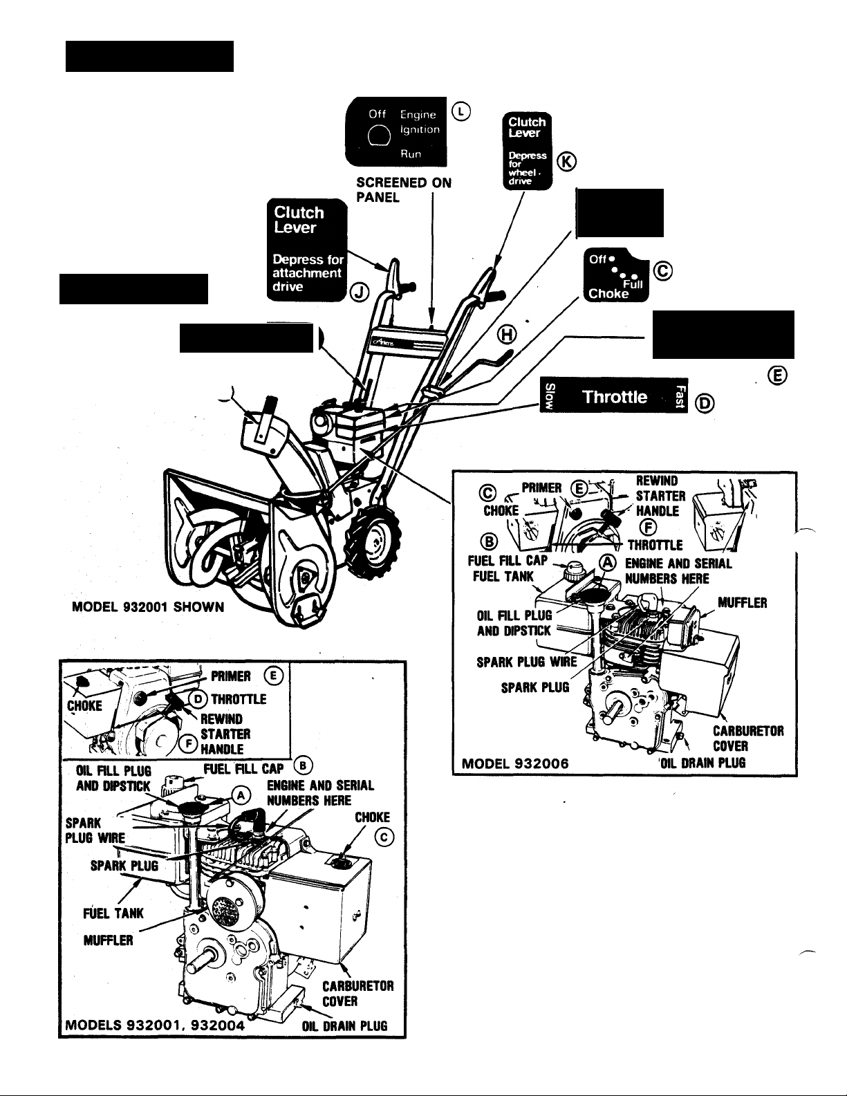
FIGURE 1
Speed Selector
4 3 2 1
(932006)
(932001, 932004) 0
Speed Selector
3 2 1 R
©
Discharge
Right Left
Engine Primer
Push to prime
-4-
Page 5

OPE
jmm
BEFORE STARTING — FIGURE 1
MPORTANT; REVIEW THE CONTROL AND COMPONENT LOCA
TIONS AND DECALS ON YOUR SNO-THRO AND SHOWN IN
FIGURE 1. READ AND REFER TO THE ENGINE INSTRUCTIONS
PROVIDED.
1. Fill crankcase with oil. Refer to Engine Instructions
Manual supplied with Sno-Thro. ©
2. Add unleaded or leaded regular gas. Do not mix oil with
gasoiine. ©
CAUTION: MAKE VISUAL CHECKS WITH REGARDS TO SAFETY
PRECAUTIONS SUCH AS OUTLINED ON PAGE 2.
TO START — FIGURE 1
1. Turn key to “RUN” position. ©
2. Move Choke Knob to “FULL” choke position.©
NOTE; 932000 SERIES CHOKE CONTROLS ARE LOCATED ON
THE ENGINE CARBURETOR COVER BOX.
3. Move Throttle to “FAST” position.®
TO OPERATE - FIGURE 1
1. Move Chute Deflector to desired height. ®
2. Turn Hand Crank to direct Discharge Chute. ® Direct
snow away from area to be cleared; the chute will adjust to
220° turn.
3. Move Speed Selector to desired speed.©
4. Depress Attachment Clutch Lever to engage snow
throwing.®
IMPORTANT; IF THE IMPELLER (FAN) IS FROZEN OR RUSTED,
THE BLOWER ATTACHMENT WILL NOT FUNCTION CAUSING
POSSIBLE DAMAGE TO BLOWER BELT AND DRIVE COM
PONENTS. BE CAREFUL TO GRADUALLY ENGAGE ATTACH
MENT CLUTCH LEVER.
5. Depress Traction Clutch Lever to drive the Sno-Thro
wheels. ®
NOTE; BOTH HANDLEBAR CLUTCH LEVERS MUST BE
DEPRESSED TO OPERATE AND BLOW SNOW.
TO STOP - FIGURE 1
4. Push Primer Bulb two or three times when engine is cold.
Below -15® F additional priming may be required.®
Turn Discharge Chute ® to left before starting. Pull Re
wind Starter. ®
a. Pull rope out slowly until the engine reaches the start of
the. compression cycle. (The rope will pull slightly
harder at this point.)
b. Let the rope rewind slowly.
c. Pull the rope with a rapid full arm stroke. Let the rope
rewind slowly — do not let the rewind handle snap.
NOTE: IF YOUR SNO-THRO IS EQUIPPED WITH AN ELECTRIC
STARTER, REFER TO THE INSTRUCTIONS PROVIDED WITH THE
STARTER.
6. When the engine starts move the Choke Knob gradually to
the “OFF” position, from 3/4, to 1/2, to “OFF”. If
engine falters move Choke Knob immediately to “FULL”
then gradually to “OFF”. ®
NOTE: TO START A WARM ENGINE DISREGARD STEP 3 (MOVE
CHOKE “OFF”), DISREGARD STEP 5 (DO NOT PUSH PRIMER).
TO TRANSPORT (TRACTION DRIVE) — FIGURE 1
1. Move Speed Selector to desired speed.®
Press down on the top of the handlebars enough to raise
the front of the Sno-Thro slightly off the ground.
1. Release Traction Clutch Lever.®
2. Except for emergency stops, allow the Sno-Thro Attach
ment Clutch to be engaged and the engine run for a short
time to throw out slush and water and prevent freezing of
the fan.
3. Release Attachment Clutch Lever.®
4. Turn key to “OFF” position. ®
5. Move Choke Knob to “FULL” position.®
6. Move Throttle to “FAST” position. ®
OPERATING TIPS
1. Snow is best removed as soon as possible after snow fall.
2. To clear an area property run the Sno-Thro in an overlapp
ing series of paths. For large areas start in the middle and
blow snow to each side so it doesn’t have to be moved
more than once.
3. Snow should be discharged with the direction of wind
whenever possible. Do not blow snow any higher than
necessary.
4. Chemicals used to melt ice and snow may damage the
finish of your Sno-Thro. When possible, wipe the Sno-Thro
clean with a rag (use of automotive wiper washer fluid may
be applied) to remove residue.
3. Depress Traction Clutch Lever to transport. ©
- 5 -
Page 6

ADJUSTMENTS/ MAINTENANCE
Ariens Company recommends that you have adjustments made
by your local Aliens dealer. He has the tools and know-how to
properly perform these maintenance adjustments which may be
required to keep the Sno-Thro operating at peak efficiency. The
Sno-Thro is equipped with the finest quality engine obtainable.
However, should servicing be required, it can be obtained from
an Ariens dealer or an authorized engine manufacturer’s service
station. Should you decide to make adjustments on your SnoThro yourself, Ariens recommends that you call your dealer for
the answers to any questions that might arise in performing this
work.
SHEAR BOLT REPLACEMENT - FIGURE 2
Occasionally an object may enter the blower and jam the rakes.
When this occurs, the shear bolts securing the rakes to the shaft
will break and allow the rake to turn freely on the shaft preven
ting damage to the gear drive. When this happens, turn off the
engine, remove wire from spark plug, remove the broken shear
bolt and replace with a new ARIENS shear bolt. Use of any other
type of shear bolt may result in severe damage to the machine.
USE ONLY ARIENS SHEAR BOLTS FOR REPLACEMENT. Each
time a shear bolt is replaced (and once each year) the rake
should be rotated on the shaft and the shaft lubricated. Refer to
“LUBRICATION” section.
RUNNERS AND SCRAPER BLADE — FIGURES 2 & 3
Lever touching the hub. If the Activator Lever touches the hub,
the attachment idler (Figure 9) must be adjusted in the idler arm.
Loosen the cap screw on the idler and move idler IN TOWARD the
belt. Readjust the spring in the chain for proper action.
Make sure that all linkage works freely so that blower idler snaps
quickly and freely to disengaged position when Attachment
Clutch Lever is released. Make sure that the blower impeller
(fan) comes to a quick (5 seconds) stop when Attachment Clutch
Lever is released.
NOTE: SEE, ALSO. “ASSEMBLY AND PRE-SERVICE” SECTION
OF THIS MANUAL.
The runners on each side of the blower housing, and the scraper
blade, along the bottom of the housing, are all adjustable to suit
conditions. Raising or lowering the runners controls the distance
the scraper blade is held above the surface being cleared. Run
ners are adjusted by loosening the two nuts securing each run
ner. Move the runner to the desired position and retighten the
nuts. Be sure to adjust both runners to the same height to keep
blower housing level. Uneven runners make the machine difficult
to steer and will result in an uneven clearing job.
Adjustment of the runners is critical to good cleaning. If the
machine is to be used on a gravel surface lower the runners so
the blower will not pick up gravel. After the remaining sno.w is
packed down, the runners may be raised for close scraping. On
smooth concrete or blacktopped surfaces, the runners may be
raised so the scraper blade rests on the surface and scrapes
clean.
The runners may be removed from the blower housing and re
installed in upside-down position to reduce contact area and thus
reduce tendency to ride up when clearing hard-packed snow.
The scraper is adjustable so it may be lowered to compensate for
wear. See Page 12 illustration. Loosen locknuts securing
scraper blade to adjust. Retighten locknuts. If the blade Is al
lowed to wear down too far the blower housing may be damaged.
ATTACHMENT CLUTCH ADJUSTMENT — FIGURES 4 &
5
The Attachment Clutch is adjusted by connecting the spring on
the clutch rod into the proper link on the Clutch Lever. Properly
adjusted, the spring should be slightly extended with the clutch
lever down. This should occur without the Attachment Activator
6-
Page 7

ADJUSTMENTS/ MAINTENANCE
CHUTE CRANK ADJUSTMENT ~ FIGURE 6
In the event the chute crank fails to rotate smoothly, loosen the
nut securing the worm clevis to the bracket. This hoie in the
bracket is slotted to permit adjustment. Position the worm so
there is a little clearance between worm and the gear teeth on the
blower. Tighten the nut. Rotate the discharge chute through its
full travel to see that it turns easily. Readjust if required.
Lubricate as described in “LUBRICATION” section for smooth
operation.
TRACTION CLUTCH ADJUSTMENT - FIG. 5, 7 & 13B
The only adjustment for the drive disc is made by adjusting the
length of the traction clutch rod. Loosen setscrew in the rod
adapter and allow clutch lever to lay down on handle grip. Shift
Speed Selector to third gear. Raise rod adapter bracket until it
clears the top of the slot in frame by 1/16“ and tighten
setscrew. See Figure 13B
Check for proper adjustment by removing the bottom cover and
measuring the space between the roll pin and bracket on the
traction rod. This space must be 1/8 - 3/16“ with clutch lever
engaged, for proper operation. See Figure 7.
REPLACEMENT OF FRICTION WHEEL - FIGURE 7
FIGURE 5
1. Adjust fuel tank level to prevent spilled gasoline. Tip the
machine up on the blower housing and brace securely.
Remove two cap screws at back of frame securing the bot-
^ tom cover and loosen two cap screws at front frame sides
^ and remove the cover.
2. Remove the four whiziock nuts holding the bearing flange
on the right hand side of the frame. Remove the bearing
flange and carriage bolts.
3. Remove the hairpin cotter from the traction clutch rod. Pull
this rod from the clutch fork arm and tip it up and out of
the way .
4. Slide the friction wheel assembly and hex shaft to the right
until the left end of the hex shaft comes free of the left
bearing. Then slip the whole assembly back to the left and
pull it forward out of the frame.
5. With the friction wheel assembly out of'the frame, the
three cap screws holding the friction wheel to the hub may
be removed and the friction wheel removed.
6. Position a new friction wheel on the hub and secure with
the three cap screws. Tighten securely.
7. Slip the right end of the complete friction wheel assembly
and hex shaft into the hole in the right side of the frame.
Position the friction wheel hub in the forks. Be sure
washers are in place on bearing flange pins. Slide the hex
shaft to the left and into the left bearing being sure flat
washer is in position. See that the pinion gear meshes with
the large gear.
7 -
FIGURE 7
Page 8

ADJUSTMENTS/ MAINTENANCE
REPLACEMENT OF FRICTION WHEEL — CONTINUED
8. Replace the bearing flange on the right side of the frame
and secure with the four carriage bolts and nuts. Recon
nect the traction clutch rod in the clutch fork arm and
secure with a hairpin cotter. Readjust the traction clutch
as described in “TRACTION CLUTCH ADJUSTMENT”
section.
BELT REPLACEMENT - GENERAL — FIGURES 8 & 9
CAUTION: SINCE REPUCING THE BELTS WILL INVOLVE TURN
ING THE ENGINE OVER WITH THE STARTER, AND THE ENGINE
MIGHT ACCIDENTALLY START RESULTING IN INJURY. THE
SPARK PLUG WIRE MUST BE DISCONNECTED DURING THIS
PROCEDURE.
The traction drive belt and the blower drive belt are both accessi
ble by tipping apart the blower housing and tractor as follows:
1. Remove the nut and lockwashers holding the worm clevis
on the bracket. Remove the chute crank by sliding it back
in the bracket and out of the way.
ENGINE SHEAVE
(BLOWER)
AHACHMENT
IDLER
TRACTION SHEAVE
^ ii J
BRAKE SHOE J
ENGINE SHEAVE
(TRACTION)
2. Remove the two screws securing the belt guard to the trac
tor. Remove belt guard.
3. Remove the top screws and loosen the lower screws on
each side that secures the blower housing to the frame. As
the blower housing and tractor are tipped apart, roll the
blower belt off the engine sheave between the sheave and
belt finger. This can be easily done by pulling the recoil
starter rope to rotate the engine sheave. See “CAUTION”
note,this section. With the blower belt disconnected, the
blower housing may then be tipped from the frame.
REPLACEMENT OF TRACTION DRIVE BELT — FIGURES
3 & 9
CAUTION: SINCE REPLACING THE BELTS WILL INVOLVE TURN
ING THE ENGINE OVER WITH THE STARTER, AND THE ENGINE
MIGHT ACCIDENTALLY START RESULTING IN INJURY, THE
SPARK PLUG WIRE MUST BE DISCONNECTED DURING THIS
PROCEDURE.
With the blower and tractor tipped apart, pull the idler away from
the traction drive belt and remove belt from around the traction
sheave and engine sheave. Install the new belt on the engine
sheave and traction sheave. Then reposition the idler back into
position on the outside of the traction drive belt.
FIGURE 8
BRAKE SHOE
FIGURE 9
With the belts in position and the idler in place, check the belt
alignment. The engine sheave and the tractor sheave must align
with one another. If the sheaves are not properly aligned, loosen
the setscrews on the engine sheave and align the sheaves.
Retighten the setscrews.
- 8
Page 9

ADJUSTMENTS/ MAINTENANCE
REPLACEMENT OF THE BLOWER DRIVE BELT —
FIGURES 8 & 9
CAUTION: SINCE REPLACING THE BELTS WILL INVOLVE TURN
ING THE ENGINE OVER WITH THE STARTER, AND THE ENGINE
MIGHT ACCIDENTALLY START RESULTING IN INJURY, THE
SPARK PLUG WIRE MUST BE DISCONNECTED DURING THIS
PROCEDURE.
The blower drive belt is on the sheave on the blower housing.
Remove and install the new belt on the sheave. Hold it in position
on the sheave as the blower is tipped into position on the tractor.
Be sure the brake shoe seats on the belt as the units are tipped
together. Once assembled, roll the blower drive belt on to the
engine sheave and position the idler on the outside of the belt.
Align blower engine sheave and blower sheave (on blower hous
ing) with attachment idler. If sheaves are not properly aligned,
loosen setscrews on the blower engine sheave and blower
sheave (on blower housing) and align with attachment idler.
Retighten setscrews. Readjust Attachment Clutch per instruc
tions on page 6.
REPLACEMENT OF BLOWER HOUSING t- FIGURES 8 &
9
CAUTION: SINCE REPLACING THE BELTS WILL INVOLVE TURN
ING THE ENGINE OVER WITH THE STARTER, AND THE ENGINE
MIGHT ACCIDENTALLY START RESULTING IN INJURY, THE
SPARK PLUG WIRE MUST BE DISCONNECTED DURING THIS
PROCEDURE.
1. Tip the blower and tractor together. Hold the blower drive
belt up as the units are tipped together. Be sure the
blower brake shoe seats on the blower sheave. Secure
with the two cap screws into the frame.
2. Roll the blower belt on to the engine sheave. Pull the recoil
starter rope to turn the engine sheave and roll the belt into
place under the belt finger.
3. Check the belt finger spacing. There should be 1/8 inch
clearance between the belt finger and belt with the attach
ment clutch engaged. Readjust the belt finger if required.
4. Check the sheave alignment with the blower belt in place.
Readjust as required to align the sheaves. It may be
necessary to tip the blower housing away from the tractor
to gain access to the blower sheave. Replace blower hous
ing by reversing the instructions found in “BELT
REPLACEMENT — GENERAL” section on page 8.
STORAGE
A
WARNING: NEVER STORE PRODUCT IN AN ENCLOSED AREA
WHERE FUEL FUMES MAY REACH AN OPEN FLAME, SPARK,
OR PILOT OF FURNACE, ETC. DRAIN FUEL OUTDOORS, AWAY
FROM OPEN FLAME, AND USE ONLY AN APPROVED FUEL CON
TAINER.
ENGINE
Refer to Engine Manufacturer's Instructions supplied with the
product.
5. Replace the belt guard and chute crank assemblies. Read
just the chute crank as described in “CHUTE CRANK AD
JUSTMENT” section. Replace the spark plug wire.
GENERAL
Store Sno-Thro in a cool, dry place.
Inspect Sno-Thro for visible signs of wear, breakage or damage.
Order any parts required and make necessary repairs to avoid
delays when beginning use again.
Lubricate Sno-Thro as described in “LUBRICATION” section of
this manual.
Clean the Sno-Thro thoroughly. Touch up all unpainted and ex
posed areas with paint to avoid rust.
Page 10

LUBRICATION
ENGINE
Fill Crankcase with oil as recommended in Engine
Manufacturer’s Instructions supplied with the product. Check oil
level before each use and change oil regularly according to
Engine Manufacturer’s Instructions.
SNO-THRO TRACTION DRIVE - FIGURE 10
At the start of each operating season, grease the hex shaft as in
dicated in Figure 10. Put a few drops of oil on the Speed Selector
linkage and other linkage points. Lubricate the bushings on the
axle as indicated in Figure 10.
NOTE: BEFORE LUBRICATING THE BUSHINGS ON AXLE
(BETWEEN THE WHEEL AND FRAME) BE SURE TO CLEAN
THE INNER SURFACES OF THE BUSHINGS. REMOVE THE
CAP SCREW (1) AND LOCKNUT (2). REMOVE WHEEL (3)
FROM AXLE. CLEAN INSIDE OF BUSHING (4) AND ADD OIL
TO INNER BUSHING SURFACE. REPLACE WHEEL.
shear bolt holes, turn rakes on shaft several times and replace^
shear bolts. See Figure 11 A.
On models equipped with zerk fittings on the rake shaft it will be
necessary to re-grease the rake shaft zerk fittings provided each
time a shear bolt is replaced and/or at the end of the season. Be
sure to rotate the rakes on the shaft several times after applying
grease. See Figure 11B.
Oil the Discharge Chute with several drops of oil See Figure 12.
Rotate the Discharge Chute after applying oil to spread oil over
the Discharge Chute gear teeth to prevent rust and provide
smooth operation.
CLEAN & OIL
FIGURE 10
SNO-THRO UNIT - FIGURES 11 & 12
The blower gear case is lubricated with Ariens Liquid Grease
(Part No. 000070). This grease will not flow at lower
temperatures, it is therefore difficult to check the lubricant level.
Best method for checking is to place the unit in a warm location
overnight. This allows the grease to flow to level. Check the
lubrication by removing the filler plug on the side of the gear
case just above the left auger shaft. Lubrication should be even
with the hole with the machine sitting level, it may be necessary
to insert a wire into the hole to check level. The unit will not be
damaged by over lubricating.
NOTE: OIL CAN (PUMP-TYPE) MAY BE USED TO LUBRICATE
WITH ARIENS LIQUID GREASE.
Some models are equipped with zerk fittings on the rake shaft.
See Figure 11B. For those models that do not have zerk fittings,
oil rake shaft periodically or each time a shear bolt is replaced. At
the end of the season, remove shear bolts, oil rake shaft through
-10-
Page 11

SNO-THRO SERVICE GUIDE
PROBLEM POSSIBLE CAUSE CORRECTION
r^-
Difficult starting, engine runs poorly.
Engine stalls or Iqoses power. 1. Choke is on after engine is
Excessive vibration.
Sno-Thro will not move. -
Sno-Thro will not discharge snow.
1.
Defective spark plug.
2.
Engine-is not getting fuel. 2. Fill fuel tank; check and clean
warm.
2. Impeller is blocked.
Water in fuel.
3.
1. Loose hardware securing
components.
Damage to unit.
2.
1. Traction Clutch is not adjusted
correctly.
2. Loose or damaged drive belt. 2.
1. Attachment Clutch is not
adjusted correctly.
1.
Replace spark plug, check
connections of plug wire.
fuel line.
1.
Turn Choke Lever to “OFF”.
2. Turn off Sno-Thro, remove
obstruction.
3. Follow Engine Instructions to drairtank and refill.
1.
Do not run unit. Stop and tighten
all hardware, check for damage.
2. See your Ariens dealer.
1.
Adjust Clutch, see “ADJUST-
MENTS-MAINTENANCE” Section of
Owner's Manual.
Replace belt - see “ADJUSTMENTS
-MAINTENANCE” section.
1.
Adjust Clutch, see “ADJUST-
MENTS-MAINTENANCE” section
of Owner's Manual.
Blower drive belt is loose
2.
or damaged.
Broken shear bolt.
■ 3.
A
4. Chute or auger is clogged. 4.
r'-
2.
Replace belt - see “ADJUSTMENTS
-MAINTENANCE” section.
3. Replace with Ariens shear bolt see “ADJUSTMENTS-MAINTE-
NANCE” section.
Turn off Sno-Thro, remove clog.
-11 -
Page 12

BASIC CONSUMER-USER SERVICE COMPONENTS
NOTE: FOR ENGINE LUBRICATION AND PARTS SUCH AS AIR
CLEANER AND SPARK PLUGS REFER TO ENGINE ENSTRUC-
TIONS MANUAL SUPPLIED WITH UNIT. CONTACT ENGINE
MANUFACTURER’S DEALER FOR REPLACEMENTS.
SHIFT HANDLE
032071
KEY SET
013157
CHUTE CONTROL CRANK
022081
SHEARBOLT
& NUT
532005
RI6HTRAKE
532014 - 20”
532016 - 24”
LEFT RAKE
532015 • 20”
532017 • 24”
RUNNER
010165
CLUTCH SPRING
083008
PARTS OR SERVICE MANUALS
Basic Consumer-User Service Components are Il
lustrated on tMs page and are described in the text
of this manual. These components are most com
monly used for consumer repair.
Should a complete parts list and/or a repair manual
less engine be required order under the following
part numbers.
Parts Manual
SPRING
083171
SHEAVE
073103
BLOWER
DRIVE
BELT
072114
TRACTION OPTIONAL ACCESSORIES*:
Repair Manual
Please Request From; AriensSorvice
For engine parts Hst and repair instructions, contact
the engine manufacturer’s dealer.
Electric Starter, 722006
Slicer Bar, 710997
Homeowner’s Kit, 732003
Tire Chains, 732001 for Model 932001;
732002 for Models 932004, 6
Part No. PM-32-82
Part No. RM932-1982
655 West Ryan Street
n, Wl 54110
OPTIONAL ATTACHMENTS*:
Rotary Brush - 24”: 832001 (RB24)
Rotary Tiller, 832004 (RT20)
‘Available at Extra Cost
Page 13

ASSEMBLY & PRE-SERVICE
WARNING: FAILURE TO FOLLOW ALL INSTRUCTIONS FOR
ASSEMBLY AND PRE-SERVICE COULD RESULT IN PERSONAL
INJURY AND/OR DAMAGE TO THE SNO-THRO. CHECK AND
TEST THE FUNCTION OF ALL CONTROLS BEFORE STARTING
ENGINE AND BE SURE TO FILL ENGINE WITH OIL.
WARNING: ALL ASSEMBLY AND ADJUSTMENT PROCEDURES
ARE TO BE MADE WITH ENGINE STOPPED AND SPARK PLUG
WIRE DISCONNECTED.
NOTE: MAKE SURE ALL SAFETY DEVICES AND GUARDS ARE IN
POSITION AND OPERATING PROPERLY. READ THE OWNER’S
MANUAL AND ITS INSTRUCTIONS FOR SAFE OPERATION
BEFORE USING UNIT.
GENERAL
The unit is shipped with tractor and snow head assembled. The
handlebars are assembled but must be installed, along with the
clutch rods and chute crank.
HANDLEBAR INSTALLATION - FIGURE 13
The handlebars are attached to the holes in the side of the frame.
Install a cap screw (59022, 3/4” long), a flat washer (64123)
and lockwasher (63003) in the lower holes on each side of the
^^handle and attach to the frame. Do not tighten. Insert a cap
^ icrew (59069,1-1 /4” long), a washer (64123) and lockwasher
t63003) through each of the upper holes in the handlebars. Hold
the handlebars up in a comfortable position and tighten all hard
ware. The handlebars are adjustable for customer use.
WIRING HARNESS - FIGURE 13
BELT
COVER
KEY SWITCH
ON PANEL
FLANGE
WHIZLOCK
SCREW
TO
FRAME
AHACHMENT
CLUTCH HANDLE
CHAIN
SPRING
TO ENGINE
MAGNETO
TAPPING
SCREW
CLAMP
KEY
SWITCH
TRACTION
CLUTCH ROD
WIRE HARNESS
1-1/4” CAP SCREW
IN UPPER HOLE
3/4” CAP SCREW
IN LOWER HOLE
BOnOM
COVER
TRACTION
CLUTCH
HANDLE
-(BENT
END OF
CLUTCH
ROD
GOES
HERE)
1/8” T0Í
3/16’
FIGURE 13A
The wiring harness is supplied attached to the engine. Run this
harness from the engine, up the left handlebar, to the key
switch. Connect wire to terminals on the key switch; wires can
be attached to either terminal. Secure the wiring harness to the
left handlebar with clamp (69099).
TRACTION CLUTCH ROD - FIGURE 13
The traction clutch rod is shipped loose in the carton. To install
the rod, place the Speed Selector in third speed; insert the bent
end of the clutch rod into the hole in the clutch handle on the left
handlebar. See Figure 13A. Insert the straight end of the clutch
rod into the hole in the rod adapter in the clutch bracket at the
left rear of the frame. See Figure 13B. Hold the clutch handle all
the way down; raise the clutch bracket up to 1/16 inch of the
frame; now tighten the rod in place with the setscrew in the rod
adapter.
This adjustment can be checked by tipping Sno-Thro onto blower
housing and removing bottom cover. To remove bottom cover,
^^remove the two screws on each side of cover that mount it to the
ame. With the clutch handle fully depressed the clearance bet
ween the roll pin and the bracket should be 1/8 inch to 3/16
inch. See Figure 13A. Loosen the setscrew and readjust if re
quired.
- 13
Page 14

ASSEMBLY & PRE-SERVICE
a. Remove belt cover located in front of engine.
b. Check alignment of blower engine sheave and blower
sheave with attachment Idler. If sheaves are not aligned
properly loosen the setscrews on the blower engine
sheave and blower sheave, then align them with the
blower idler. Retighten setscrews. See Figure 14.
c. Insert a 3/16” thickness shim (use a 1” wide flat
stock) between the brake shoe and the attachment
drive belt on the blower sheave. See Figure 14.
d. With the 3/16” shim installed, adjust the attachment
Idler in the slot toward blower drive belt until it is just
snug against belt. See. Figure 14. Remove shim. Ad
justment should be re-checked after completion of at
tachment clutch assembly.
e. Check and, if necessary, adjust the belt fingers so
there is approximately 1/16” clearance between at
tachment drive belt and belt fingers when attachment
clutch is engaged. See Figure 14.
f. Check attachment clutch handle function. There should
be total travel of handle down and up (to point of con
tact of handle center on handlebar) and free movement
of the handle.
AHACHMENT
CLUTCH
ROD SPRIHG
©
m
AHACHMENT CLUTCH LEVER
FIGURE 1SB
g. Attachment clutch rod spring ® should be Installed by
hooking the end of the rod spring up through the hole in
the Attachment Clutch Lever on the right rear of SnoThro frame. See Figure 15B. Connect the spring end of
the attachment clutch rod spring to a link in the chain
® on the attachment clutch handle as shown in Figure
15A. With the handle in the disengaged (up) position
select a link that will allow the spring to stay slack (not
extended) and will extend the spring a minimum of
3/8” length when the handle is engaged (down posi
tion). When clutch is disengaged the brake shoe must
engage the attachment drive belt on the blower sheave.
h. Check function of attachment clutch. The blower at-^
tachment must stop running within five (5) second!.
-14-
Page 15

ASSEMBLY & PRE-SERVICE
ATTACHMENT CLUTCH - CONTINUED
after attachment clutch handle is disengaged (up posi
tion). If this is not achieved, check blower idler adjust
ment according to paragraph "d" (attachment drive
belt tension may be too tight) and belt finger adjust
ment (paragraph "e"). Reinstall belt cover.
CAUTION: PROPER FUNCTION OF ATTACHMENT CLUTCH CAN
BE ASSURED ONLY WHEN THE PREVIOUS STEPS IN “ATTACH
MENT CLUTCH” SECTION HAVE BEEN PERFORMED.
CHUTE CONTROL CRANK — FIGURE 16
The chute control crank is shipped fully assembled and In place
in the bracket. Install as follows: Bolt the crank clamp in place
on the left handlebar. See Figure 16.
Position the worm clevis on the bracket on the blower housing.
Place external tooth lockwasher between worm clevis and
bracket. Adjust in slot so that there is a little clearance between
worm and gear teeth on blower collar.
Secure the worm clevis with the carriage bolt (already in place on
the clevis). Use a lockwasher (63023) and a 5/16-18 nut
(65015) under the bracket. See Figure 16.
Rotate the discharge chute through its full travel to see that it
turns easily. Readjust the position of the worm clevis, if re
quired. Oil discharge chute, see Figure 17B.
DEFLECTOR - FIGURE 17
The deflector is shipped in place on the discharge chute but
must be raised into operating position. Remove the locking hard
ware from the discharge chute. Raise the deflector up into posi
tion. Re-install the hardware as shown In Figure 17A. Adjust the
nut to apply sufficient tension so the deflector can be easily
moved by hand but will still hold position when blowing snow.
BLOWER GEAR CASE
The blower gear case is factory lubricated and should require no
lubrication by the dealer.
The blower gear case Is lubricated with Ariens Liquid Grease
(Part No. 000070). This grease will not flow at lower
temperatures. It is therefore difficult to check the lubricant level.
Best method for checking is to place the unit in a warm location
overnight. This aliows the grease to flow to level. Check the
lubrication by removing the filler plug on the side of the gear
case just above the left auger shaft. Lubrication shouid be even
with the hoie with the machine sitting level. It may be necessary
to Insert a wire into the hoie to check levei. The unit will not be
damaged by over lubricating.
-15
Fill crankcase with oil as recommended in Engine
Manufacturer’s Instructions supplied with the product. Check oil
level before each use and change oil regularly according to
Engine Manufacturer’s Instructions.
Page 16

ASSEMBLY & PRE-SERVICE
TIRE PRESSURE
Models 932004 and 932006 are equipped with pneumatic tires.
Adjust pressure to 12 to 20 PSI before operating. Tire pressure
of 20 PSI is recommended for use with tire chains.
REGISTRATION
Fill out pre-warranty registration card and mail to Ariens Com
pany. Warranty will only be registered under the model and
serial number found on the serial number label (also stamped in
to the frame of the unit). Add serial numbers in serial number
recording area of this manual.
DELIVERY
Using the Owner’s Manual as a guide, instruct the customer as
follows:
1. Instruct the customer on the operation of the Sno-Thro.
Emphasize safety and discuss the safety information in the
Owner’s Manual.
2. Advise customer to change oil in the engine crankcase
after the first two hours of operation.
3. Explain how to perform the recommended lubrication and^
periodic service.
4. Explain maintenance and adjustment instructions.
5. Demonstrate how to mount and dismount attachments.
6. Make certain the customer has his Owner’s Manual and
Engine Instructions.
7. Explain Ariens Warranty Policy. Fill out and return Ariens
Warranty Registration Card.
SERIAL NUMBER — SNO-THRO
(PLATE LOCATED ON REAR OF FRAME)
SERIAL NUMBER — ENGINE
(STAMPED INTO TOP OF ENGINE ABOVE RECOIL START)
A message to the Ariens customer...
Welcome to the world of Ariens equipment. We are pleased that you have selected Ariens and sincerely believe you have pur
chased the best equipment available. The care you give your new Ariens equipment will greatly determine the satisfaction and ser
vice life you will obtain from it. Use this manual and the engine manual supplied, as your guide. By observing the instructions and
suggestions in these manuals, your Ariens equipment will serve you well for many years.
Your Ariens dealer will be happy to supply any service or advice which may be required to keep your Ariens equipment operating at
peak efficiency. He stocks genuine Ariens parts and lubricants; manufactured with the same precision and skill as the original
equipment. His factory trained staff is kept well informed on the best methods of servicing Ariens equipment and is ready and able
to serve you. If engine repairs or services are required, they can be obtained from an Ariens dealer or from an authorized engine
manufacturer’s service station. If service is required, be prepared to supply the service person with the Model Number and Serial
Number of the equipment and the engine, as well as a full description of the problem encountered.
-16-
 Loading...