

Page 1
9^i1ens
Series
Sno-Thro®
Repair
Manuai
Ÿ/tS^
Ariens
Page 2

A Message To Ariens Repair Manuai User
Your Ariens Dealer will be happy to supply any
service or advice which may be required to
keep your Ariens equipment operating at peak
efficieny. He stocks genuine Ariens parts and
lubricants; manufactured with the same preci
sion and skill as the original equipment. His
factory trained staff is kept well informed on
the best methods of servicing Ariens equip
ment and is ready and able to serve you. If
engine repair or service are required, they can
be obtained from an Ariens dealer or from an
authorized engine manufacturer’s service
center. If service is required, be prepared to
supply the service person with the Model and
Serial Numbers of the equipment and engine,
as well as a full description of the problem
encountered.
The information contained herein is intended
for use by Ariens Dealers’ trained servicemen
and serves as a supplement to and reminder of
training sessions conducted by Ariens Com
pany. Before you attempt any repair, adjust
ment or maintenance project be certain that
you have read and fully understand the instruc
tions in your Owner’s Manual. Understand and
follow each Danger, Warning, Caution and all
instructions exactly as given. Also be sure that
you have Parts Manuals, all tools, replacement
parts and other materials required to complete
the project.
IMPORTANT: All fittings, measurements, tor
que recommendations and instructions are
significant and approximations or substitu
tions must be avoided. Improper repair,
maintenance and/or adjustments or service at
tempted by anyone other than an authorized
Ariens Service Dealer could void future warran
ty claims, and damage unit and/or result in in
jury to operator and/or bystanders.
4
Page 3

Introduction
How To Use Your Service Manual
I
The Ariens Service manual is arranged for
quick, easy reference and is divided into
numerical sections. Each section is then divid
ed into sub-sections. To use this manual pro
ceed as follows:
Refer to the index to determine section within
Which desired information will be contained
and proceed to front of that section for its
Table of Contents.
Locate subject desired. Page number is listed
across from subject and consists of section
number and page number.
NOTE: Read all information for servicing a part
or system before repair work is started to avoid
needless disassembly.
Preparation For Service
Proper preparation is very important for effi
cient service work. A clean work area at the
start of each job will allow you to perform the
repair as easily and quickly as possible, and
I
reduce incidences of misplaced tools and
parts. A sno-thro that is excessively dirty
should be cleaned before work starts. Cleaning
will occasionally uncover trouble sources.
Tools, instruments and parts needed for the
job should be gathered before work is started.
Interrupting a job to locate tools or parts is a
needless delay.
Service Buiietins
In addition to the information contained in this
Ariens Service Manual, Ariens Service
Bulletins are issued to Ariens Dealers from
time to time, which cover interim engineering
changes and supplementary information. Ser
vice Bulletins should be consulted to complete
information on models covered by this manual.
Replacement Parts
When replacement parts are required, use only
genuine Ariens parts. Failure to do so may
result in product malfunction and possible in
jury to operator and/or bystander.
NOTE: All references to “Left”, “Right”,
“Front” and “Back” are given from operators
position.
NOTE: The descriptions and specifications
contained in this manual were in effect at the
time the manual was approved for printing.
Ariens company reserves the right to discon
tinue models without notice and without incur
ring obligation. The equipment identified as
either standard or optional and the various il
lustrations may not all be applicable to your
unit. If you have questions, always check with
your Ariens dealer.
»
©Ariens 1987
RM-932
Part No. 000128A
Printed in U.S.A. 11-87
Page 4

Safety Alert Symbol And Notations
The following safety notations are used
throughout this manual to call attention to
special information or operating procedures.
Understand the message in each notation and
be alert to unsafe conditions and the possibili
ty of personal injury.
NOTE: A NOTE points out general reference in
formation regarding proper operation and
maintenance practices.
A
A
CAUTION: A CAUTION identifies safe
operating practices or indicates unsafe
conditions that could result in personal
injury.
WARNING: A WARNING describes a con
dition where failure to follow the instruc
tions could result in severe personai
injury.
i
IMPORTANT: An IMPORTANT statement in
dicates specific procedures or information
that is required to prevent damage to the
machine or its attachments.
This safety alert symbol is used to at
A
Before test operating or making repair or ad
justments to the unit, read and understand the
operating and safety instructions in the
Owner’s Manual.
Disengage power to attachment, stop engine,
remove key and wait for moving parts to stop
before performing any repair or maintenance
adjustment procedures. DO NOT make any ad
justment or perform any maintenance or repair
procedures while engine is running unless
specifically instructed to do so in this manual.
DO NOT touch tractor or attachment parts
which might be hot from operation. Before at
tempting to maintain, adjust or service, allow
such parts to cool.
Open doors if engine is run in garage, exhaust
fumes are dangerous. DO NOT run engine in an
enclosed area.
Do repair work in a well-lighted, ventilated
area.
To prevent accidental starting, disconnect wire
to spark plug(s) and position wire away from
plug.
Always wear safety goggles when cleaning or
making repairs to parts or machine.
tract your attention! PERSONAL SAFETY
IS INVOLVED! When you see this symboi
- BECOME ALERT — HEED ITS
MESSAGE.
A
Safety Precautions
DANGER: A DANGER designates a con
A
dition where failure to follow instruc
tions or heed warning will most likely
result in serious injury or death.
A
Gasoline is highly flammable and its vapors
are explosive. Handle with care. Use an approv
ed fuel container. DO NOT smoke or allow
open flame (match, pilot light, etc.) or sparks
near equipment or fuel container when refuel
ing or servicing fuel system.
Use non-flammable solvent to clean parts - DO
NOT use gasoline.
Use only Ariens original replacement parts
when making repairs.
After all repair procedures are performed,
make sure that unit is in good operating condi
tion and all safety devices and shields are in
place and in good working condition. Be sure
all fasteners are tight, all adjustments are cor
rect and all tools are removed.
DO NOT change engine governor setting or
over speed engine.
Never store equipment with fuel in tank inside
a building where fuel fumes may reach an open
flame or spark. Allow engine to cool before
storing in any enclosure.
Page 5

Index
Section
Specifications
Handlebars and Clutch
Controls.....................................
Speed Selector and Wheels .
Belt Drive...................................
Friction Wheel...........................
Auger/Impeller -
Discharge Chute
...........................
.......................
Gear Case
Engine and Headlight...............
Attachments
..................................
..............................
Page 6

Specifications
Length
Height ........................................................
Clearing Width....................
Shipping Weight......................................... 97 ibs. to 160 ibs.
WheeiSize
Engine, Horsepower
Fuel
Governed R.P.M
Discharge Distance
AirCieaner................................................... Required with Summer Attachment
Engine Oii................................................... 10W30, 5W30 Winter - 30W Summer
Spark Piug Gap
Drive ........................................................... Auger or Friction Wheei
Forward Speed........................................... 4 Forward on Wheei Driven
.................................
..................................................
..................................
.............................................................
.........................................
...................................
................
.......................
.......................
.........................
49 to 60 inches
39 to 40 inches
20” to 24”
(8”x13/4”) (4.10/3.50-4)
2.7 to 5 H.P., 120 Voit AC Eiectric
Unleaded - 1 Quart to 2 Quart Tanks
3600 (4500 Elect. Model)
3’ to 25’
RJ 17 LM Champion-.030
Variable on Auger Propelled
Reverse Speed
Eiectric Start Avaiiable
Headlight Avaiiable ..................................
Auger R.P.M................................................ 100
Chute Turning Angle
Auger Diameter
Impeiier Diameter
Auger Impelier Housing
Frame
.........................................................
...........................................
..............................
.................................
..........
...............................
............................
...........................
.........
1 Reverse on Wheel Driven
Yes (Except Eiectric Modei)
Yes (Except Eiectric Model)
220°
11”
10”
18 GA. (2-1-2 Modeis)
16 GA. (Standard Modeis)
16 GA. (2-1-2 Modeis)
14 GA. (Standard Modeis)
Page 7

Handlebar and Clutch Controls
Table of Contents
Page
2.1 Introduction.....................................................................................................■ ■ 2-6
2.2 Attachment Clutch.............................................................................................2-6
2.3 Attachment Clutch Adjustment.........................................................................2-6
2.4 Wheel Drive Clutch ...........................................................................................
2.5 Wheel Drive Clutch Adjustment........................................................................2-7
2.6 Handlebar and Key Switch................................................................................2-8
2.7 Lower Handlebar................................................................................................2-8
2.8 Handlebar Height Adjustment
..........................................................................
2-7
2-8
List of Illustrations
2-1: Controls and Features (Wheel Driven Models)................................................2-2
2-2: Controls and Features (Auger/lmpeller Driven Models)
2-3: Handlebars and Clutch Controls.......................................................................2-4
2-4: Attachment Clutch Adjustment.........................................................................2-6
.................................
2-3
2-5: Wheel Drive Clutch Adjustment (Inside Frame)
2'<6: Wheel Drive Clutch Adjustment.................................................................... 2-7
2-7: Wheel Clutch Adjustment (Models with Straps)..............................................2-8
2-1
..............................................
2-7
Page 8

Handlebars and Clutch Controls
1. Chute Deflector
2. Discharge Chute
3. Auger/Impeller Housing
4. Auger
5. Impeller
6. Scraper Blade
7. Runner(s)
8. Belt Guard
9. Fuel Tank and Cap
10. Speed Selector
Figure 2-1: Controls and Features (Wheel Driven Models)
2-2
11. Attachment Clutch Lever
12. Key Switch
13. Wheel Drive Clutch Lever
14. Oil Fill and Dipstick
15. Choke
16. Throttie
17. Spark Plug and Wire
18. Primer Buib
19. Rewind Starter
20. Chute Crank/Handie
Page 9
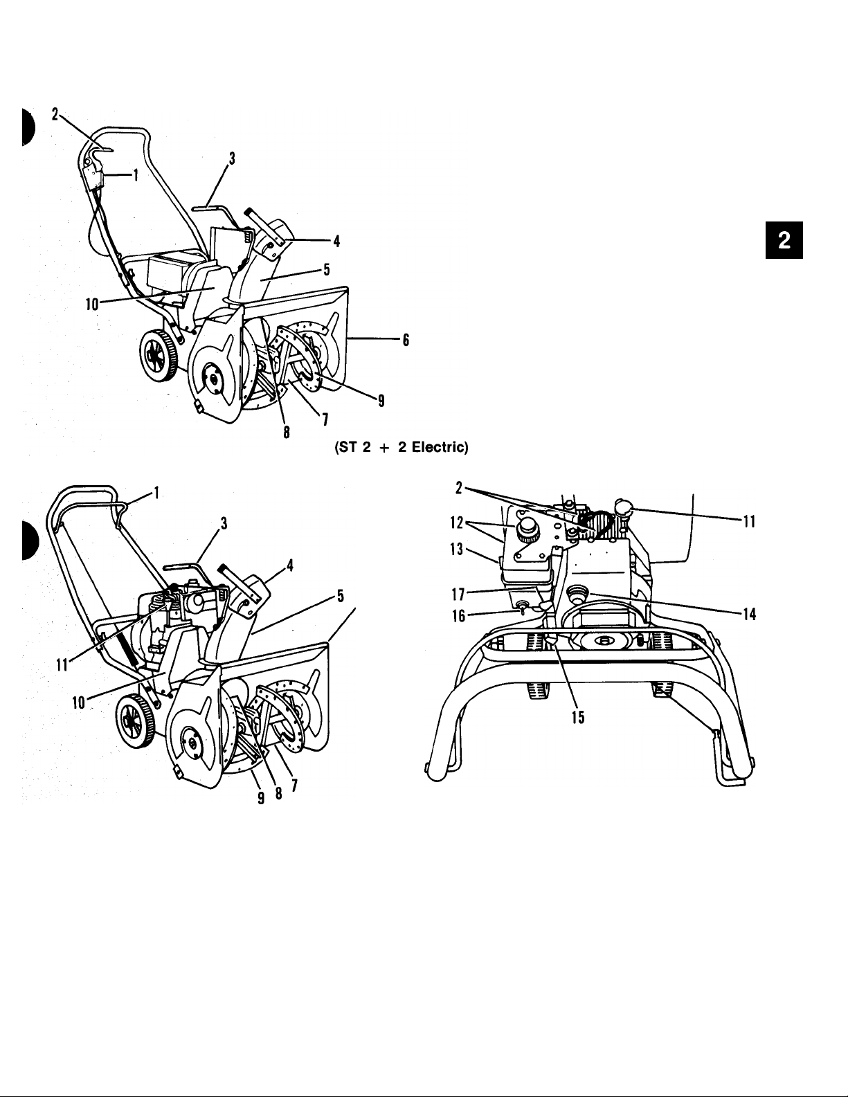
Handlebars and Clutch Controls
1. Switch Key
2. Switch Controi
3. Chute Controi Lever
4. Deflector
5. Discharge Chute
6. Auger/Impeller Housing
7. Scraper Blade
8. Impeller
9. Auger
10. Belt Guard
1. Attachment Clutch Bail
2. Spark Plug and Wire
3. Chute Control Lever
Chute Deflector
4.
5. Discharge Chute
Auger/Impeller Housing
6.
7. Scraper Blade
Impeller
8.
9. Auger
(ST 2 + 2 Gasoline)
Figure 2-2: Controls and Features (Auger/Impeller Driven Models)
10. Belt Guard
11.
Oil Fill and Dipstick
12. Fuel Tank and Cap
13.
Choke
14. Primer Bulb
15. Recoil Start
16. Engine Ignition (Key Switch)
17. Throttle
2-3
Page 10

Handlebars and Clutch Controls
i
i
Figure 2-3: Handlebars and Clutch Controls
2-4
Page 11

Handlebars and Clutch Controls
ITEM
NO.
»
1
2
3
4
5
6
7
8
9
10
11 Key Set
12
13
14
15
16
17
18
19
20
21
22
23
ITEM
DESCRIPTION
Clutch Spring
Chain and Connector
Cap Screw, 1/4-20 X 1/2
Attachment Clutch Lever
Lock Nut, 1/4-20
Tapping Screw, #12-14 X 1-1/2 29
Pin
Push Nut 31
Handle Pivot
Nut, 5/8-32
Lock Washer, 5/8
Key Switch Assembly 36
Grip
Handlebar 38
Flange Whiziock Nut, 5/16-18 39
Carriage Bolt, 5/16-18 X 1-1/2
Cable
Cover 42
Traction Clutch Lever
Hook Rod
Adjustment Strap
Flange Whiziock Screw, 5/16-18 X 5/8
NO.
DESCRIPTION
24
25
26
27
28
30
32
33
34
35
37
40
41
43
44
45
46
47
Washer, 3/8
Lower Handlebar
Carriage Bolt, 5/8-16 X 1/2
Handlebar Panel
Clamp
Shorting Wire
Taptite, 1/4-20 X 3/8
Tapping Screw, #8-15 X 3/8
Remote Stop Terminal
Traction Clutch Rod
Washer, 5/16
Lock Washer, 5/16
Cap Screw, 5/16-18 X 3/4
Cap Screw, 5/16-18 X 1-1/2
Bail
Machine Screw, 10-24 x 1-1/2
Tie
Curved Head Boit
Washer, .312/.343 x .625 x .062
Washer, .370/.390 x .875 x .083
Extension Spring, 5-1/4
Control Box
Knob
Quadrant Doubler
»
2-5
Page 12

Handlebars and Clutch Controls
2.1 Introduction
WARNING: Remove wire from spark
A
When unit is tipped to perform service pro
cedures in this section, remove enough fuei so
that no spiilage wiil occur, block securely, and
remove bottom cover.
A
plug before attempting any repair or
adjustment procedures.
WARNING: Gasoline is highly flam
mable and its vapors are explosive.
Handle with care.
2.2 Attachment Clutch
On models with spring and chain, remove push
nuts, screws and pin holding clutch handle and
handle pivot to upper handlebar. Remove pivot
and disconnect clutch handle from chain and
connector.
Assemble using reverse procedure and adjust
according to instructions in Attachment
Clutch Adjustment Section.
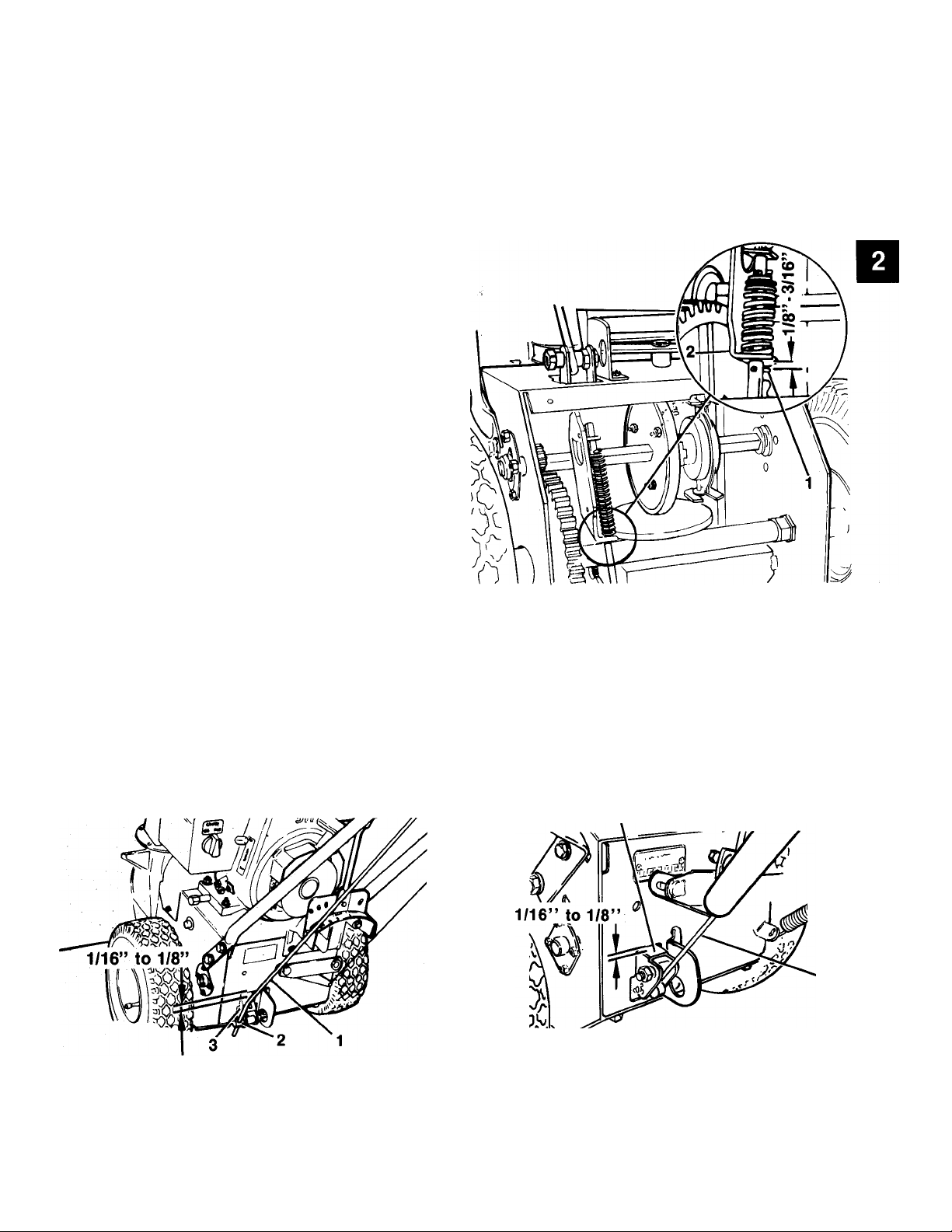
2.3 Attachment Clutch Adjustment
On models with spring and chain, adjust by
connecting spring to a chain link so chain is
snug, but so that attachment idler drops away
from attachment belt with Clutch Handle all
the way away from handlebar.
On models with adjustment strap, select and
mark a hold in adjustment strap that will pro
vide a slight amount of slack in cable with At
tachment Clutch all the way away from
handlebar. Unhook spring, place cable end
through hole selected above and while lifting
up on attachment clutch arm, connect spring.
WARNING: When clutch is engaged,
A
impeller brake disengages. If brake is
not 1/16” to 1/8” from belt when
disengaged, refer to Attachment
Clutch/Impeller Brake Section.
i
Disconnect chain and clutch spring from lever.
Check parts for wear or replacement.
Assemble using reverse procedure and adjust
according to instructions in Attachment
Clutch Adjustment Section.
On models with adjustment strap, remove
push nuts and pin holding clutch lever to
handlebar. Remove lever and disconnect
clutch cable from adjustment strap.
Disconnect adjustment strap and clutch
spring from attachment clutch arm.
On models with bails, remove bail from
handlebar by removing push nuts.
Check parts for wear or replacement.
1. Attachment Belt Idler
2. Attactment Drive Belt
3. Brake Shoe
Figure 2-4: Attachment Clutch Adjustment
2-6
Page 13
Handlebars and Clutch Controls
^ 2.4 Wheel Drive Clutch
On models with traction rod and rod adapter,
remove push nut, tapping screws and pin
hoiding handle pivot and wheei drive clutch
handle to handlebar. Remove handle pivot and
wheel drive clutch handle.
Remove set screw in rod adapter and remove
traction clutch rod.
On models with adjustment strap, remove
push nut and pin holding clutch lever to
handlebar and remove cable from clutch lever.
Remove hook rod from traction clutch arm and
adjustment strap.
Check parts for wear or replacement.
For assembly and adjustment procedure see
Wheel Drive Clutch Adjustment Section.
Check for proper adjustment by measuring
distance between roll pin and bracket on trac
tion rod. Distance must be 1/8 - 3/16” with
clutch engaged.
2.5 Wheel Drive Clutch Adjustment
Adjust wheel drive clutch to compensate for
wear of friction wheel when slippage occurs.
On models with rod adapter, adjust by loosen
ing set screw in rod adapter, pushing clutch
handle down on handle grip, and shifting
speed selector to third gear. Raise rod adapter
so top of bracket clears top of slot in frame by
1/16” to 1/8” and tighten set screw.
1.
Roll Pin
2.
Bracket
Figure 2-5: Wheel Drive Ciutch Adjustment
(inside Frame)
1. Traction Clutch Rod 1. Hook Rod
2. Rod Adapter 2. Bracket
3. Bracket
Figure 2-6: Wheel Drive Ciutch Adjustment
2-7
Page 14

Handlebars and Clutch Controls
Oh models with adjustment strap, adjust by
selecting and marking a hole in adjustment
strap that will provide a slight amount of slack
in cable. Unhook hook rod, place cable end
through hole selected above and while lifting
up on traction clutch arm connect hook arm to
traction clutch arm.
IMPORTANT: With Wheel drive clutch engag
ed, clutch bracket should be within 1/16” to
1/8” from top of slot in frame on adjustment
strap and rod adapter models.
Check parts for wear or replacement.
Assemble using reverse procedure.
2.7 Lower Handlebar
Remove hardware attaching lower handlebar
to each side of frame and remove lower
handlebar from'frame.
Check parts for wear or replacement.
Assemble using reverse procedure.
2.8 Handlebar Height Adjustment
CAUTION: On models with adjustable
A
handlebars, whenever handlebar
height is changed. Attachment and
Wheel Drive Clutches, as well as
Speed Selector on models with Speed
Selector on Handlebar Panel, must be
adjusted to insure proper operation of
machine.
1. Cable End
2. Adjustment Strap
3. Hook Rod
4. Traction Clutch Arm
Figure 2-7: Wheel Clutch Adjustment
(Models with straps)
2.6 Handlebar and Key Switch
Disconnect wires to key switch (unplug cable
from motor on electric model).
Remove key switch nut and lock washer and
remove key switch from upper handlebar panel
or heater box.
Remove handlebar panel from handlebar by
removing machine screws or upper handlebar
and panel by removing carriage bolts.
On 2-I-2 models, separate lower and upper
handlebar by removing curved head bolt, ad
justing knob, lock washer and washer connect
ing upper and lower handlebar on each side.
On models with adjustable handlebars, the
standard Speed Selector rod that comes with
Sno-Thro allows for handlebar height adjust
ment for the average user (from low to about
mid height range). For those who wish to
operate unit with handlebar adjusted up to it’s
maximum height, a longer Speed Selector rod
(Part Number 032245) is available.
Lower handlebar mounting holes are slotted to
provide variable handlebar height. To adjust,
loosen handlebar mounting hardware, select a
safe comfortable operating height, and tighten
hardware. Torque to 150 inch pounds.
NOTE: A 63023 pyramid style lock washer is
recommended in place of the flat washer to
lock handlebar at a selected height especially
for hard usage.
On 2 -I- 2 Models with adjustable handlebars,
adjust by disconnecting clutch cable and
removing upper handlebar from lower
handlebar.
Remove hardware that attaches lower
handlebar to frame, turn lower handlebar over
(side to side), and secure with hardware just
removed. Secure upper handlebar to lower
handlebar and attachment clutch cable.
1
2-8
Page 15

Speed Selector and Wheels
Table of Contents
Page
3.2 Speed Selector Removal................................................................................... 3-2
3.2 Speed Selector Adjustment (Models with Speed Selector mounted to
handlebar panel)............................................................................................ 3-2
3.3 Wheel Assembly............................................................................................... 3-3
List of Illustrations
Page
3*1: Speed Selector and Wheels..............................................................................3-1
3-2: Speed Selector (Models with Speed Selector)
3-3: Speed Selector (Models with Speed Selector on handlebar panel).............3-2
3-4: Speed Selector Adjustment...............................................................................3-3
3-5: Speed Selector
3-6: Wheel...................................................................................................................3-3
.........
.........................................................................................3-3
............................................
3-2
Page 16

Speed Selector and Wheels
2
3
4
5
1. Speed Selector
2. Shift Retainer
3. Quadrant
4. Friction Wheel
Figure 3-1: Speed Selector and Wheels
5. Drive Plate
6. Shift Fork
7. Shift Rod
8. Handlebar Panel
3-1
Page 17
Speed Selector and Wheels
3.1 Speed Selector Removal
On models with lower speed selector, remove
two taptites securing shift handie retainer to
quadrant and remove retainer.
Remove taptite securing speed selector to
quadrant. Remove taptites securing quadrant
to frame and remove speed selector and
quadrant from frame.
Inspect parts for wear or replacement
assemble using reverse procedure.
and
3.2 Speed Selector Adjustment (Models with Speed Selector mounted to handlebar panel)
NOTE: Refer to Handlebars and Clutch Con
trols Section for handlebar height adjustment
procedure.
On models with adjustabie handlebars, after
adjusting handlebar height (from about mid to
low standard setting), loosen nuts on Speed
Selector rod at rod adapter enough to allow
Speed Selector to be positioned in first (1)
speed slot. Position Speed Selector arm
parallel with top of frame and tighten nuts to
lock rod in position.
To achieve maximum safe operating height of
handlebar utilizing standard rod, place Speed
Selector in first (1) speed, position lower nut to
end of rod (with threads fuliy engaged) and
lock rod in position with top nut. Raise
handlebar until Speed Selector arm is parallel
to top of frame and secure handlebar.
1. Taptite
2. Speed Selector Retainer
3. Quadrant
4. Grip
5. Speed Selector
6. Retainer and Nut
Figure 3-2: Speed Selector
(Models with lower speed selector)
On models with Speed Seiector on handlebar
panel, remove nut, bolt, washer, spring and
spacer attaching Speed Selector to handlebar
panel and remove Speed Selector. Remove
gear selector rod from Speed Selector.
Remove lower nut from bottom of Speed
Selector rod and remove rod from rod adapter.
Inspect parts for wear or replacement.
1. Cap Screw
2. Washer
3. Spacer
/\ii
12
13
^ 12
14
Figure 3-3: Speed Selector
(Models with Speed Selector on handlebar
panel)
3-2
4. Compression Spring
5. Speed Selector
6. Grip
7. Push Nut
8. Hole Plug
9. Shift Pivot
10. Lock Nut
11. Shift Rod
12. Lock Nut
13. Swivel
14. Cap
10
Page 18
Speed Selector and Wheels
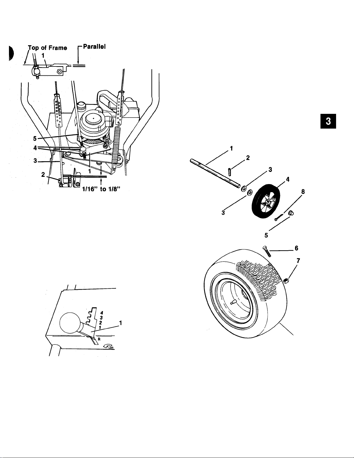
3.3 Wheel Assembly
Remove cap or cap screw and lock nut secur
ing wheel onto axle and remove wheel from
axle.
Check parts for wear or replacement.
Assemble using reverse procedure.
1. Speed Selector Arm
2. Traction Clutch Arm
3. Hook Rod
4. Speed Selector Rod Nuts
5. Speed Selector Rod
Figure 3-4: Speed Selector Adjustment
1. First Speed Slot
1.
Axie
2.
Roii Pin
Washer
3.
4.
Wheei
5. Cap
6. Cap Screw
7. Lock Nut
8. Cotter Pin
Figure 3-5: Speed Selector
Figure 3-6: Wheei
3-3
Page 19

Belt Drive
Table of Contents
Page
4.1 Introduction....................................................................................................... 4-6
4.2 Attachment Drive Belt....................................................................................... 4-6
4.3 Traction Drive Belt.............................................................................................4-6
4.4 Attachment Clutch/lmpeller Brake....................................................................4-7
List of Illustrations
Page
4-1: Belt Drive System
4-2: Belt Drive Exploded View (Wheei Driven iViodeis)...........................................4-2
4-3: Beit Drive (Auger Driven Modeis)......................................................................4-4
4-4: Drive Beit (Auger Propeiied Modeis)
4-5: Drive Belts (Wheel Drive Modeis)......................................................................4-6
............
...................................................................................4-1
.................................................................
4-6
Page 20

Belt Drive
Wheel Driven Models
1. Attachment Drive Pulley
2. Attachment Belt
3. Attachment Idler
4. Attachment Pulley
Figure 4-1: Belt Drive System
5. Traction Drive Pulley
6. Idler Arm
7. Traction Drive Pulley
8. Traction Idler
4-1
Page 21

Belt Drive
Figure 4-2: Belt Drive (Wheel Driven Models)
4-2
Page 22

Belt Drive
ITiM
NO.
I
H Belt Cover
2 Taptite, 1/4-20 X 3/8
3
4
5
6
7 V-Belt (Attachment Drive)
8
9
10
11 Woodruff Key, 1/8 X 5/8
12 Camshaft Pulley
13
14
15
16 Roll Pin; 5/32 X 7/8
17 Washer, 1/2
18
19
20
DESCRIPTiON
Belt Finger
Washer, 5/16
Lock Washer, 5/16
Cap Screw, 5/16-24 X 3/4
Straight Key, 3/16 X 3/16 X 1”
Engine Pulley
Set Screw, 5/16-18 X 3/8
V-Belt (Traction Drive)
Lock Washer, 5/16
Extension Spring
Flanged Bushing
Cover
Lever
ITEM
NO. DESCRIPTION
21 Clutch Lever
22
23
24
25
26
27
28
29 Spacer Bushing
30 Lock Nut, 5/16-18
31
32 Idler
33
34 Idler Arm
35
36
37
38
39
40 Engine
Lock Nut, 5/16-18
Hub
Pulley
Flange Whiziock Nut, 5/16-18
Extension Spring
Cap Screw, 5/16-18 X 5/8
Washer, 5/16
Washer, 5/16
Shoulder Spacer
Carriage Bolt, 5/16-18 X 1-1/4
Oval Rivet
Brake Lining
Brake Clutch Arm W/Lining
Torsion Spring
I
V
4-3
Page 23

Belt Drive
Figure 4>3: Belt Drive (Auger Driven Models)
4-4
Page 24

Belt Drive
i
ITEM
NO. DESCRIPTION
1
2
3
4
5
6
7
■ 8
9
10
11 :
12
13
14
15
Belt Cover
Taptite, 1/4-20 X 3/8
Taptite, 3/8-16 X 1
, Engine/Motor
Push Nut
Washer, .526/.546 x 1.062 x .095
Frame
Center Lock Nut, 1/4-20
Arm
Flange Bushing
Cap Screw, 1/4-20 x 5/8
Oval Rivet
Brake Lining
Washer, .370/,390 x .875 x .083
Two Way Lock Nut, 5/16-18 x 1-3/8
ITEM
NO.
16
17
18
19 Clutch Arm w/Lining
20
21
22
23
24
25
26 V-Belt
27
28 Belt Finger
29 Cap Screw, 5/16-24 x 3/4
30
DESCRIPTION
Carriage Bolt, 5/16-18 x 1-3/8
idler
Bearing Spacer
Torsion Spring
Spacer
Extension Spring
Straight Key, 3/16 X 1 X 3/16
Motor/Engine Pulley
Set Screw, 5/16-18 x 3/8
Lock Washer, 5/16 ID
Washer, .328 x .875 x 7 GA.
4-5
Page 25

Belt Drive
4.1 Introduction
WARNING: Remove wire from spark plug
A
When unit is tipped onto housing, remove
enough fuel so that no spillage will occur,
block securely and remove bottom cover.
A
NOTE: Auger/Impeller Housing and frame must
be tipped apart to perform repairs in this sec
tion. Refer to Auger/Impeller Section of this
manual.
A
before attempting any repair or adjust
ment procedures.
WARNING: Gasoline is highly flammable
and its vapors are explosive. Handle with
care.
CAUTION: After new belts have been
installed, Clutches must be adjusted
per instructions in Handiebars and
Ciutch Controls Section to insure pro
per function.
4.2 Attachment Drive Belt
Remove attachment drive belt from pulley
(hold brake away from belt).
Place attachment drive belt on auger/impeller
pulley, and while holding brake out of way, tip
unit together. Assemble unit in reverse order.
NOTE: Make sure pulleys align. If alignment is
necessary, loosen attachment pulley set
screws, reposition pulley and tighten set
screws.
WARNING: When clutch is engaged, im
peller brake disengages. If brake is not
1/16 to 1/8” from belt when disengaged,
A
refer to Attachment Clutch/Impeller
Brake Section.
4.3 Traction Drive Beit
Pull idler away from belt and remove belt from
idler pulley, engine and drive pulley (it may be
necessary to turn engine pulley using rewind
starter).
NOTE: To gain clearance, engage traction
clutch and pull back attachment idler arm
clevis pin.
Replace traction drive belt in reverse order
making sure pulleys align. If alignment is
necessary, loosen engine pulley set screws,
reposition pulley and tighten set screws.
Check alignment of attachment drive pulley
and align according to above instructions if
necessary.
I
1
1. Engine Puiiey
2. Attachment Puiiey
3. Attachment Drive Beit
4. Attachment Brake
Figure 4-4: Drive Beit (Auger PropeNed Modeis)
1. Attachment Brake
2. Attachment Pulley
3. Attachment Drive Belt
4. Attachment Idler
Figure 4-5: Drive Belts (Wheel Driven Models)
4-6
Engine Attachment
Pulley
Engine Drive Pulley
Drive Belt
Traction Idler
1
Page 26

Belt Drive
4.4 Attachment Clutch/Impeller Brake
WARNING: With improper use, injury
A
Figure 6-4: Attachment Clutch and Impeller
may result if attachment clutch lever is
released and brake DOES NOT STOP
auger/impeller within 5 seconds.
1. Spring Extension
2. Brake Shoe
3. Attachment Drive Beit
Brake
To check and/or adjust impeller brake, tip unit
forward onto auger/impeller housing. Remove
bottom cover by removing rear and loosening
front cap screws.
Measure distance between impeller brake
shoe and belt with attachment clutch engaged.
When attachment clutch is disengaged, brake
must contact belt.
If impeller brake shoe is not 1/16 to 1/8 inch
from belt, disengage clutch (release bail),
loosen attachment idler nut, reposition idler to
compensate for belt length, and tighten nut.
Adjust attachment clutch cable with clutch
disengaged. Pull clutch chain taught and con
nect chain link to spring. Spring should extend
approximately 3/8” with clutch engaged. With
ciutch disengaged, clutch arm should fall to its
maximum down position.
V"‘
4-7
Page 27

Friction Wheel Drive
Table of Contents
Page
5.1 Introduction........................................................................................................5-4
5.2 Friction Wheei Removal
5.3 Drive Plate Removal...........................................................................................5-4
5.4 Clutch Fork Removal.........................................................................................5-4
5.5 Friction Wheel Drive..........................................................................................5-6
....................................................................................
5-4
List of Illustrations
Page
5-1: Friction Wheei System.......................................................................................5-1
5-2: Friction Wheei Expioded View...........................................................................5-2
5-3: Friction Wheei.....................................................................................................5*4
5-4: Reduction Drive System
5'5: Reduction Drive (Expioded View)......................................................................5-6
....................................................................................
5-5
Page 28

Friction Wheei Drive
.4
-5
1. Hex Shaft
2. Bearing Flange
3. Shift Fork
4. Friction Wheel
5. Drive Plate
6. Clutch Fork
7. Drive Pulley
Figure 5-1: Friction Wheel System
8. Drive Belt
9. Idler Arm
10. Spring
11. Axle Shaft
12. Gear
13. Pinion Gear
14. Traction Clutch Assembly
5-1
Page 29

Friction Wheel Drive
Figure 5-2: Friction Wheei
5-2
Page 30

Friction Wheel Drive
ITEM
NO.
1
2
3
4
5
6
7
8
9
10
11
12 Friction Wheel Hub
13
14
15
16
17
18
19
20
21
OESCRIPTION
Compression Spring 22
Shifting Fork 23
Flanged Bushing
Washer, 1/2
Cap Screw, 5/16-18 x 1-1/2
Washer, 5/16
Lock Nut, #10-24 28
Bushing Flange 29
Bearing Flange
Washer, 1/2 31
Lock Nut, 1/4-20
Friction Wheel
Cap Screw, 1/4-20 X 1/2
Roll Pin, 1/8 X 7/8
Pinion -
Carriage Bolt, #10-24 x 3/8
Snap Ring, External
Cap Screw, 1/4-20 x 1-3/4
Clevis Pin
Cotter Pin, 3/32 X 3/4
ITEM
NO.
24 Hairpin, 3/32 X 1-3/16
25
26
27
30
32
33
34 Woodruff Key, 3/16 x 3/4
35 Washer, 5/8
36
37
38
39
40
41 Hex Shaft
42 Spacer
DESCRIPTION
Cap Screw, 5/16-18 x 3/4
Traction Clutch Assembly
Clutch Fork
Set Screw, 5/16-18 x 3/8
Rod Adapter
Lock Nut, 5/16-18
Bracket
Cotter Pin, 1/8 X 1”
Cap
Spacer
Extension Spring
Flange Bushing, Long
Drive Plate
Hex Shaft
Lock Nut, 3/8-16
Flange Bushing
-n
5-3
Page 31

Friction Wheei Drive
5.1 Introduction
WARNING: Remove wire from spark plug
A
When unit is tipped onto housing, remove
enough fuel so that no spillage will occur,
block securely and remove bottom cover.
A
before attempting any repair or adjust
ment procedures.
WARNING: Gasoline is highly flammable
and its vapors are explosive. Handle with
care.
Remove three cap screws securing friction
wheel to hub and remove friction wheel.
Secure new friction wheel onto hub with three
cap screws and torque cap screws to 8-10 foot
pounds.
Assemble using reverse procedure.
NOTE: Position friction wheel hub in forks. Be
sure washers are in place on bearing flange
pins. Slide hex shaft to left and into left bear
ing with flat washers in position. Pinion gear
must mesh with large gear.
5.3 Drive Plate Removal
Remove auger/impeller housing and bottom
cover according to instructions in Auger/-
Impeller Section.
Remove attachment drive belt according to in
structions in Belt Drive Section and remove ex
tension springs from idlers.
1. Friction Wheel
2. Cap Screw
3. Bearing Flange Screws
4. Clutch Fork
5. Extension Spring
6. Frame
Figure 5-3: Friction Wheel
5.2 Friction Wheel Removal
Tip unit onto housing and remove bottom
cover by removing four Cap screws.
Remove bearing flange screws on right hand
side of frame and remove bearing flange.
Remove hairpin cotter from traction clutch rod,
pull rod from clutch fork arm and tip up and out
of way.
Slide friction wheel assembly and hex shaft to
right until left end of hex shaft comes free of
left bearing. Slip assembly back to left and pull
forward out of frame.
Remove drive plate return spring and bearing
flange from frame opposite axle gear, and
remove friction wheel.
Remove set screws from attachment pulley
hub and remove attachment pulley and hub.
Remove drive plate assembly, and remove fric
tion plate and bearing flange from assembly by
removing snap ring.
NOTE: Apply Loctite Anti-Sieze to hex end of
shaft before placing friction plate back onto
assembly.
Assemble using reverse procedure.
5.4 Clutch Fork Removal
Remove friction wheel assembly according to
instructions in Friction Wheel Removal Sec
tion and remove axle.
Remove cap from outside of frame and cotter
pin from clutch fork rod. Remove clutch fork.
Inspect parts for wear or replacement and
assemble using reverse procedure.
5-4
Page 32

Friction Wheel Drive
ITEM
NO. DESCRIPTION
1
2
3
4
5
6 Bushing Flange
7
Roll Pin, 1/8 X 7/8
Hex Shaft
Pinion 10
Washer, 1/2 11
Flanged Bushing
Carriage Bolt, #10-24 x 3/8
Figure 5-5: Reduction Drive (Expioded View)
5.5 Friction Wheei Drive
Remove friction drive assembly according to
instructions in Friction Drive Section.
Remove cap screw and lock nut securing
reduction gear to axle shaft and remove axle
ITEM
N0.
8
9
12
13
DESCRIPTION
Lock Nut, 1/4-20
Gear
Cap Screw
Axle Shaft
Flanged Bushing
Lock Nut, #10-24
and gear from frame.
Inspect parts for wear or replacement.
Assemble using reverse procedure.
5-5
Page 33

Auger/Impeller - Discharge Chute
Table of Contents
Page
6.1 Introduction.............................................................................................................6-5
6.2 Auger/Impeller Housing.........................................................................................6-5
6.3 Auger/impeiler Removal.........................................................................................6-5
6.4 Attachment Clutch/Impeller Brake........................................................................6-5
6.5 Scraper Blade..........................................................................................................6-6
6.6 Auger Rubber..........................................................................................................6-6
6.6 Shear Bolt Replacement........................................................................................ 6-7
6.8 Runners...................................................................................................................6-7
6.9 Discharge Chute Removai.....................................................................................6-7
6.10 Discharge Chute Adjustment (Models without crank)
6.11 Chute Crank Adjustment (Models with crank mounted to ieft
handlebar)...........................................................................................................6-9
6.12 Chute Crank Adjustment (Models with crank through handiebar
panel)...................................................................................................................6-9
....................................
List of Illustrations
6-1
6-2
6-3
6-4
6-5
6-6
Auger/Impeller System....................................................................................6-1
Discharge Chute Exploded View
Auger/impeiler Housing...................................................................................6-4
Attachment Clutch and Impeller Brake
Shear Bolts and Scraper Blade.......................................................................6-6
Auger Rubber Replacement............................................................................6-6
....................................................................
..........................................................
6-8
Page
6-2
6-5
6-7
6-8
6-9
6-10: Discharge Chute (Modeis with crank mounted to left handlebar)
6-11: Discharge Chute Adjustment (Models with crank mounted to left
Runners.............................................................................................................6-7
Discharge Chute (Modeis with crank through handiebar panei)
Discharge Chute Gears...................................................................................6-8
handlebar.................................................................................................................6-9
................
................
6-8
6-8
Page 34

Auger/Impeller-Discharge Chute
8 9 10 1
1. Crank Rod (Handle)
2. Impeller
3. Gear Case
4. Scraper Blade
5. Runner
6. Auger/Impeller Housing
7. Auger
8. Discharge Chute
Figure 6-1: Auger/impelier System
6-1
9. Worm Gear
10. Worm Cievis
11. Chute Deflector
12. Gear Cover
Page 35

Auger/Impeller - Discharge Chute
%\
w
Figure 6-2: Discharge Chute (Expioded View)
6-2
Page 36

Auger/lmpeller - Discharge Chute
I
ITEM
KO.
1
1
3
4
5 Gear Bracket
6
7
8
9
10
11
12
13
14
15
16
17
18
19 Washer, 5/16
20
21
22
23
24 Cap Screw, 5/16-18 X 1/2
25
26
27 Machine Screw, 1/4-20 X 3/4
28 Lock Nut, 1/4-20
29
30 , Grip
DESCRIPTION
Taptite, 1/4-20 X 3/8
Gear Cover
Push Nut
Taptite, 1/4-20 X 3/8
Washer or Bushing 36 Carriage Bolt, 1/4-20 X 1-1/4
Hair Pin
Chute Pinion Gear
Cap Screw, 1/4-20 X 1-1/2
Lock Washer, 1/4
Washer, .312/.343 X .875 X .062
Cap Screw, 5/16-18 X 5/8
Chute Strap
Spacer
Washer, .312/.343 X .875 X .062
Lock Washer, 5/16 ID
Cap Screw, 5/16-24 X 3/4
Lock Nut, 5/16-18
Wave Washer
Plastic Washer
Deflector
Carriage Bolt, 5/16-18 X 3/4
Discharge Chute
Tapping Screw, 8-32 X 3/8
Chute Control Bracket
ITEM
NO. DESCRIPTION
31
32
33
34 Roll Pin, 1/8 X 3/4
35 Worm Gear
37
38
39 Lock Washer 3/8
40 Nut, 5/16-18
42
43 Chute Control Strap
44 Flange Whiziock Nut, 1/4-20
45
46 Hex Nut, 1/4-20
47
48
49 Compression Spring
50
51
52
53 Chute Gear
54
55
56
57 Nut, 1/4-20
58 Chute Handle
59 Carriage Bolt, 3/8-16 X 2
60
61
Cap
Carriage Bolt, 1/4-20 X 1-1/4
Chute Control Crank
Worm Clevis
Lock Washer, 5/16
Carriage Bolt, 1/4-20 X 5/8
Washer, 1/4
Lock Nut, 3/8-16
Washer, 3/8
Friction Plate
Friction Washer
Gear Strap
Carriage Bolt, 3/8-16 X 2-1/4
Washer, 1/4
Lock Washer, 1/4
Lock Washer, 5/16
Lock Nut, 5/16-18
6-3
Page 37

Auger/Impeller • Discharge Chute
ITEM
NO.
1
2
3
4
5
6
7 Cap Screw, 5/16-18 x 5/8
8
9
10 Lock Nut, 3/8-16
11
12
13
14
16
DESCRIPTION
Auger/Impeller Housing
Flange Whiziock Screw, 5/16-18 x 1/2
Washer, 3/4
Bearing Flange w/BushIng
Flange Whiziock Nut, 1/4-20 21
Lock Washer, 5/16
Washer, 5/16
Flange Bushing
Washer, 3/8
Runner
Rib Neck Bolt, 1/4-20 x 1/2
Carriage Bolt, 3/8-16 x 3/4
Flange Whiziock Nut, 1/4-20
Center Lock Nut, 1/4-20
Figure 6-3: Auger/Impeller Housing (Exploded View)
ITEM
N0.
17
18
19
20
22
23
24 Auger
25
26
27 Carriage Bolt
28
29 Hub
30 Flange Whiziock Nut, 5/16-18
31 Pulley
32 Set Screw
6-4
DESCRIPTION
Scraper Blade and Scraper Support
Lock Nut # 10-24
Auger Rubber w/Hardware
Machine Screw, #10-24 x 5/8
Washer, 3/16
Spin Drive Zerk Fitting
Washer, 17/64
Center Lock Nut, 1/4-20
Shear Bolt
Rib Neck Bolt, 5/16-18 x 3/4
Page 38

Auger/Impeller - Discharge Chute
6.1 Introduction
WARNING: Stop engine, remove key,
A
When unit is tipped onto housing, remove
enough fuel so that no spillage will occur,
block securely and remove bottom cover.
A
wait for moving parts to stop and remove
wire from spark plug before leaving
operator’s position and attempting to
maintain or inspect auger.
WARNING: Remove wire from spark plug
before attempting any repair or adjust
ment procedures.
WARNING: Gasoline is highiy flammabie
and its vapors are explosive. Handie with
care.
6.2 Auger/Impeller Housing
Remove pulley from auger/impeller assembly
and pull gear case and auger/impeller
assembly free of housing.
Remove shear bolts and remove augers from
shaft.
Check parts for wear or replacement.
Assemble using reverse procedure.
NOTE: Make sure pulleys align. If alignment is
necessary, loosen attachment pulley set
screws, reposition pulleys and tighten set
screws.
6.4 Attachment Clutch/Impeller Brake
WARNING: With improper use, injury
A
may result if attachment clutch lever is
released and brake DOES NOT STOP
auger/impeller within 5 seconds.
Remove nut and lockwashers holding worm
clevis to housing and position crank out of
way.
On auger propelled models, remove nut secur
ing chute bracket to engine/motor, and remove
chute.
On models with flat gear, remove hardware
securing chute bracket to engine and remove
hair pin securing chute rod to pinion gear.
Remove chute rod and lift discharge chute off
augeryimpeller housing.
Remove two screws securing belt guard to
tractor arid remove belt guard.
Remove top screws and loosen lower screws
that secure impeller housing to frame on each
side and tip tractor and impeller housing apart.
Assemble using reverse procedure.
6.3 Auger/Impeller Removal
Remove (3) nuts holding bearing flange to
housing on each side, remove cap screw,
lockwasher and washer on each side holding
auger shaft, and remove bearing flange with
bushing.
1. Spring Extension - 3/8”
2. Brake Shoe
3. Attachment Drive Belt
Figure 6-4: Attachment Clutch and Impeller
Brake
To check and/or adjust impeller brake, tip unit
forward onto auger/impeller housing. Remove
bottom cover by removing rear and loosening
front cap screws.
Measure distance between impeller brake
shoe and belt with attachment clutch engaged.
When attachment clutch is disengaged, brake
must contact belt.
If impeller brake shoe is not 1/16 to 1/8 inch
from belt, disengage clutch (release bail),
loosen attachment idler nut, reposition idler to
compensate for belt length, and tighten nut.
6-5
Page 39

Auger/Impeller - Discharge Chute
Adjust attachment clutch cable with clutch
disengaged. Pull clutch chain taught and con
nect chain link to spring. Spring should extend
approximately 3/8” with clutch engaged. With
clutch disengaged, clutch arm should fall to its
maximum down position.
6.5 Scraper Blade
IMPORTANT: If blade wears too far, auger/im-
peller housing may be damaged.
Scraper blade on models with runners is ad
justable to compensate for wear.
To adjust scraper blade, tip unit back onto
handlebar, support housing, and loosen nuts
retaining blade. With runners adjusted to their
full up position, reposition scraper blade down,
flush with runners, and tighten lock nuts.
6.6 Auger Rubber
On 2 -I- 2 models, the rubber edges on auger
will wear and require replacement after a
period of use. Two replacement kits are
available.
The first procedure replaces both the right and
left augers requiring the removal of the augers
and impeller from the auger/impeller housing.
Then removing augers from auger shafts, plac
ing new augers onto auger shafts and reas
sembling unit.
3 1
Shear Bolt
Scraper Blade
Auger
Figure 6-5: Shear Bolts and Scraper Blade
On 2 + 2 models, scraper blade is adjustable
to compensate for wear and to control traction.
Best operation occurs if scraper blade edge
leaves a fine dusting of snow with auger tracks
(auger propels unit). Adjust scraper blade
equally its full length if machine does not
scrape cleanly or if machine does not drive for
ward properly.
To adjust scraper blade, tip unit back and rest
unit on handlebar. Loosen nuts on carriage
bolts along scraper support. If unit does not
scrape cleanly, move scraper blade forward. If
unit does not drive forward and scraper blade
drags, move scraper blade to the rear.
I
1. Drill {Va” or larger)
2. Auger
3. Rubber Edge
4. Access Hole
Figure 6-6: Auger Rubber Replacement
The second procedure replaces the rubber
edges and requires the drilling off of rivets
holding old rubber edge to segment by means
of a 1/4” diameter or larger drill bit. (An access
hole is provided on sides of auger/impeller
housing for access to outer rivets.) Then posi
tioning new rubber edge on segment and se
curing with bolts, flat washers and lock nuts.
NOTE: Be sure scraper support is fully engaged
in groove of scraper blade. Tighten hardware
and test unit. Repeat adjustment as required
until proper operation is obtained.
NOTE: After repiacement of auger rubber
edges, adjust scraper biade per instruction in
Adjustments Section.
6-6
Page 40

Auger/Impeller - Discharge Chute
6.7 Shear Bolt Replacement
IMPORTANT: Use only Ariens Shear Bolts for
replacement. Use of any other type of shear
bolt may result In severe damage to unit.
Occasionally an object may enter auger/
impeller housing and jam auger, breaking
shear bolts which secure auger to shaft. This
allows auger to turn freely on shaft, preventing
damage to gear drive.
To replace shear bolt, slide auger outward and
align hole in shaft with hole in auger (holes in
shaft for shear bolts line up). Drive new shear
bolt through hole (if old shear bolt was broken,
this will drive remaining part from shaft), and
secure with nut.
6.8 Runners
CAUTION: Adjust auger/impeller hous
ing height to clear gravel or crushed
A
rock surfaces.
Position Sno-Thro on a flat, level surface. Ad
just runners by inserting a spacer of desired
thickness under center of scraper blade,
loosen hardware, slide runners to flat surface
and tighten hardware.
Note: Above method keeps housing level by ad
justing runners equally. Uneven runners make
machine difficult to steer and result in uneven
clearing.
6.9 Discharge Chute Removal
On models with discharge chute crank rod
going through handlebar panel, remove hair
pin from discharge chute crank rod and slide
rod out through handlebar panel. Remove hard
ware attaching bracket to engine/motor and lift
discharge chute off auger/impeller housing.
Remove gear cover by removing two taptites
on cover.
Remove flat gear by removing nut securing car
riage bolt to center of flat gear.
Runners should be adjusted as conditions re
quire. Raising or lowering runners controls
distance scraper blade is held above surface
being cleared. When operating machine on
gravel surface, lower runners so that housing
will not pick up gravel. On concrete, blacktop,
or packed down snow surfaces, raise runners
so scraper blade scrapes clean. To reduce
tendency of housing to ride up over heavy, wet,
or hard-packed snow, remove runners and in
stall with narrow edge down.
1. Runner
2. Adjusting Hardware
3. Auger Housing
Figure 6-7: Runners
Remove pinion gear by removing push nut that
secures pinion gear to gear bracket and slide
pinion gear out of gear bracket.
1. Hair Pin
2. Mounting Hardware
3. Discharge Chute Crank Rod
4. Brace
5. Gear Cover
6. Spacer
7. Taptites
Figure 6-8: Discharge Chute (Models with
crank through handlebar panel)
6-7
Page 41

Auger/Impeller - Discharge Chute
On models with discharge chute crank rod
mounted to left handlebar, remove nut and
bolt securing worm clevis to bracket. Remove
bolt securing crank clamp to handlebar,
remove retainer clips at bottom of discharge
chute, and remove discharge chute from
auger/impeller housing.
Inspect parts for wear or replacement and
assemble in reverse order (apply oil to
discharge base). Adjust according to instruc
tions in Chute Crank Adjustment Section.
1. Taptite
2. Gear Cover
Discharge Chute Crank Rod
3.
Push Nut
4.
Gear Bracket
5.
Washer
6.
7. Plastic Bushing
Figure 6-9: Discharge Chute Gears
NOTE: When installing pinion gear with 5/8”
diameter hub, do not use plastic bushing.
To assemble, position discharge chute over
opening on auger/impeller housing and secure
by fastening brace to engine with mounting
hardware (spacer goes under brace at front,
washers and lock washers go under head of
cap screws on top of brace).
Place discharge chute crank rod through grom
met in handlebar panel and into gear on
discharge chute. (Rod has two holes. Select
hole that provides best operator comfort and
secure with hair pin.)
To adjust tension, tighten nut that secures flat
gear flush with end of bolt, then tighten or
loosen the nut to set the desired tension.
To adjust amount of friction between flat gear
and pinion gear, loosen bolt that secures chute
control strap to discharge chute, adjust chute
control strap up or down (hole in chute control
strap is slotted) and tighten bolt.
11. Carriage Bolt
12. Hair Pin
1. Discharge Chute
2. Mounting Clips
Figure 6-10: Discharge Chute (Models with
crank mounted to left handelbar)
On models without cranks, remove mounting
clips from discharge chute by removing bolts
securing mounting clips to auger/impeller
housing and remove discharge chute.
On 2 -f 2 models, remove capscrews securing
bracket to engine/motor and lift chute off
auger/impeller housing.
Inspect parts for wear or replacement.
Assemble using reverse procedure.
6.10 Discharge Chute Adjustment
(Models without crank)
Position discharge chute over opening on
auger/impeller housing and secure chute
handle to bracket. Tighten nut until it is flush
with end of bolt.
Swivel discharge chute from side to side to
see that it moves freely.
If discharge chute is not seated with proper
tension on bracket, loosen cap screws secur
ing bracket to engine/motor, adjust bracket to
desired tension and tighten cap screws.
«
6-8
Page 42

Auger/Impeller - Discharge Chute
6.11 Chute Crank Adjustment
(Models with crank mounted to
I
left handlebar)
Loosen nut securing worm clevig to bracket.
Position worm gear with siight ciearance be
tween worm gear and discharge chute gear
teeth, and tighten nut on bracket.
Lubricate discharge chute gear teeth and
lower base of discharge chute with oil and
move chute from side to side to see that it
moves freely.
6.12 Chute Crank Adjustment
(Models with crank through
handlebar panel)
The two brackets that attach flat gear to
discharge chute are slotted for adjustment.
Adjust so that pinion gear and flat gear mesh
together smoothly and tighten hardware.
1. Discharge Chute Gear Teeth
2. Worm Clevis
3. Nut
4. Discharge Chute
5. Worm Gear
Figure 6-11: Discharge Chute Adjustment
(Models with crank mounted to left
handlebar)
6-9
Page 43

Table of Oontenti^,^
m
' v^чÄ-»i*^Ш>ílìïáí^ " ' ï 'iS
im AMwmbiy
:/ 7;:'
7 “ .4 ■ '
/ ,4
Л
I ,'í':rv‘ »tiifl
i i
/
H
i. %.vw-
'•/4^
^4'',’-.
..........
? i . - ^
............
1*,^
^...V
.........................................
'î . . • . . l . A • • .....
7-3
...................
' '
X ■ . , . , ,4 ,
is7*'r'"' ':вт:ч: lev í" '\/í '
?-,-7
!S ;
.■; ì
,7 :
si ' ■'
:í у ^ . .
А ;■',;
' '
v.,4'
/lg¡* itti ,’*.■■•■' ■■
■'■ '--П îl \
/
.'AfA :Л7Г1 '
.'k'v Í yVf i.«:
у 'J :. 'yiÿ'ki
,, W'. .;¥■'!, A,,
/' ^ ■
./V r ■ ... ;. y A. : ^
,-7í7
■■/ -
V '‘'..i
^ '’- \ '■ ■ ' ';’'
4
“-Ч ‘‘'
" ' Г.. ’ 7лршт ШЁт^шштт
■■ ' ‘ * r-j шпе гэн, -
' V5'¥
Vi
€ . ^<
A
> ’ ‘ '^
P. i- A-
mm,
. C '
i-r-v.,« ■*'A ‘
■:. 7s'
í 7i"> .“J.'". .‘ i. S 77.v-r;
"1 ■..•-•
¥<Ï7- À'tri ‘K77.7fdr.í.№7, \fv; 'V7'‘V ^4:,: rjl,:':. ^v;;1fi ^
7 ' »saO tfmB :77'
',4i
'7 •
-------
4 7^
Ч
..A.
..............................
''■ Ч
■' •''Г. \ ’
s’*
'',\í
-
r'
Ж-^фт^-
^ v4- •
'■i'»
'V 4‘'"i'-4-
«-Л. '7'V
{■7,
;■■ . ■ ■ ■ 1 ■ ■ ■ ' .' .
in 4 Г4-П;-у
'■
-
4U -' í ' A '
%) ^
■’ 4 'vji
V ‘ ' ,,' l'v. V >;nS!
íl'V •; V, sv uí"'il ijvvnvÄA; v77
77 :;••?¥;■ V vjn 7 I, ¡'A> m.:.
fvvvy H'. 75tCÍ Sí7l7 лЬ^ШлГ
, ■-
- \Jr:^
7‘ ?
a' 'í/***
rá.
A-i
' I -
■ , ’'í'4í>
y
r' y
ft г
4 , t II
m ^
'..
Л=,
"•
I!'
4.v«S..v7, ,,
Па,.;
■ M
Page 44

Gear Case
Figure 7-1: Gear Case
7-2
Page 45

Gear Case
ITEM
N0.
t
1
2
3 0-Ring 3/4 I.D.
4 Roll Pin 1/4 X 1-1/4
5
6 Radial Bearing 3/4 ID X 1-3/4 OD
7 Center Lock Nut 1/4-20
8
9 Set Screw 5/16-18 X 3/8 (932015)
10 Pulley 1-1/4 X 7
11
12
13 Woodruff Key 3/16 X 7/8 X 3/8
14
15
16 Thrust Collar
17 L.H. Gear Case Half 34
7.1 Introduction
ITEM
DESCRIPTION
Groove Pin 3/16 X 1-1/4
Flanged Bushing 3/4 X 1” X 3/4
Bearing Flange 22
Rib Neck Bolt 5/16-18 X 3/4
Flange Whiziock Nut 5/16-18
Hub
Bearing Flange 31
Impeller 32
N0.
DESCRIPTION
18
19
20
21
23
24
25
26
27
28
29
30
33
Impeller Shaft and Worm Gear Set
Carriage Bolt 1/4-20 X 1-1/4
Seal 3/4 I.D.
Washer .805/.842 X 1.469 X .134
Flange Whiziock Nut 1/4-20
Flanged Bushing 1/2 X 3/4 X 3/4
Taptite 3/8-16 X 1/2
Carriage Bolt 1/4-20 X 7/8
Taptite #10-24 X 3/4
Washer .750/.760 X 1.400 X .062
Woodruff Key 3/16 X 5/8 X 1/4
Gasket
R.H. Gear Case Half
Auger Shaft
Gear Case Assembly
8 Cz. Tube Ariens Liquid Grease
Grease Fill
Remove impeller shaft from gearcase and slide
front flanged bushing off front of impeller
shaft.
WARNING: Remove wire from spark plug
before attempting any repair or adjust
ment procedures.
When unit is tipped onto housing, remove
enough fuel so that no spillage will occur,
block securely and remove bottom cover.
WARNING: Gasoline is highly flammable
and its vapors are explosive. Handle with
A
care.
Remove Auger/Impeller and gearcase from
housing according to instructions in
Auger/Impeller Section to perform the follow
ing procedures.
7.2 Gear Case
Remove six (6) bolts holding right and left gear-
case halves together and remove halves from
rake shaft.
Remove seals from outsides of gearcase
halves with screwdriver, and remove bushings
from outside in with bearing driver.
Slide 0-Ring and rear flanged bushing off rear
of impeller shaft.
Drive groove pin out of thrust collar and
remove thrust collar from rear of impeller shaft
(drive pin in direction of least resistance).
Remove washers located on each side of
bronze gear. Slide bronze gear off rake shaft
and remove woodruff key from rake shaft.
Inspect all parts and replace if necessary.
Place all parts back on impeller shaft and rake
shaft in reverse order.
Insert assembled rake shaft into left gearcase
half and fill gearcase with 2 oz. of Ariens Liquid
Grease, Part No. 000072.
Insert assembled impeller shaft into left gearcase half, making sure flanged bushings are
seated correctly.
Replace gearcase gasket and slide right gearcase half onto rake shaft. Turn input shaft
clockwise until gearcase halves fit snugly
together. Secure with six (6) bolts.
When properly assembled, input shaft should
turn freely.
7-3
Page 46

Engine and Headlight
Table of Contents
Page
8.1 Introduction....................................................................................................... 8-3
8.2 Engine Oil.......................................................................................................... 8-3
8.3 Engine Cooling.................................................................................................. 8-3
8.4 Engine Oil Recommendations..........................................................................8-3
8.5 Headlight............................................................................................................ 8-3
8.6 Engine Air Cleaner.............................................................................................8-4
8.7 Headlight Assembly...........................................................................................8-4
8.8 Add-On Alternator............................................................................................. 8-4
8.9 Sparkplugs..........................................................................................................8-4
List of Illustrations
Page
8-1: Engine Components......................................
8-2: Alternator/Headlight............................................................................................8-2
.....................................................
8-1
Page 47

Engine and Headlight
1. Primer Bulb
2. Choke
3. Throttle
4. Key Switch
5. Oil Fill Spout
6. Rewind Starter
7. Gas Cap
8. Spark Plug
Figure 8-1: Engine Components
8-1
Page 48

Engine and Headlight
Models 724039, 40, 41
12
Fits 932001 S/N 043801 >
Fits 932004 S/N 035001 >
Fits 932006 S/N O5830l>
Fits 932007 S/N 001301 >
Fits 932015,18,19,20
ITEM
N0.
1 Alternator Shaft 3”
2
3
4
5
6
7 Cap Screw, 1/4-20 x 1-3/4
8
9
10
DESCRIPTION
(Tec. 590613) (932000 Series)
Centering Tub, 2.7 to 5 HP (Tec. 590610)
Alternator (Tec. 611077)
Self-Tapping Screw (Tec. 650868)
Lighting Connector (Tec. 611078)
Headlight Bracket
(932019, 20)
Cap Screw, 1/4-20 x 1-1/4
(93 2001 ,4,6 ,7,15 ,18)
Lock Nut, 1/4-20
Washer, 1/4
Conduit Clamp
Figure 8-2: Alternator/Headlight
ITEM
N0.
11 Headight Assembly (724039)
12 Headlight
13
14 Switch Boot (724039)
15 U-Bracket
16
17
18 Carriage Boit, 5/16-18 x 1”
19
20
21
DESCRIPTION
Headlight Assembly (724040, 41)
Push Button Switch (724039)
Lock Washer 5/16
Cap Screw, 5/16-18 x 2-1/2
Lock Washer, 5/16
Nut, 5/16-18
Flange Whiziock Nut, 5/16-18
(Consists of items 12 thru 21)
8-2
Page 49

Engine and Headlight
8.1 Introduction
r
WARNING: Stop engine, remove key,
A
A
wait for moving parts to stop and remove
wire from spark plug (keep wire away
from spark plug to prevent accidental
starting) before attempting any lubrica
tion or maintenance procedures.
CAUTION: DO NOT touch engine or SnoThro drive parts which are hot from
operation. Allow such parts to cool
before servicihg unit.
8.2 Engine Oil
Checking
The engine crankcase oil should be checked
daily or every 5 hours of operation. Oil level
MUST be maintained in safe operating range
on dipstick at all times or engine damage will
result
r
To check oil, park sno-thro on a flat, level sur
face, stop engine, and wipe all debris from
around dipstick cap. Remove dipstick and wipe
oil off. Screw dipstick assembly firmly but
slowly until cap bottoms on tube. Remove
dipstick and observe oil level.
Drain crankcase by removing oil drain plug.
When oil has drained, replace plug and refill
engine with new oil of proper grade (per engine
manufacturer’s instructions). Recheck oil level
with dipstick.
8.3 Engine Cooling
The engine is air cooled. Air must circulate
freely around engine from air intake screen,
over cooling fins on cylinder head and block to
prevent overheating.
Every 100 operating hours or yearly (more often
if conditions require) remove blower housing
and clean cooling fins. Also clean external sur
faces of your engine of dust, dirt and oil
deposits which can contribute to improper
cooling.
IMPORTANT: DO NOT operate engine with
cooling shrouds removed. This will cause
overheating and engine damage.
Fill crankcase with oil as recommended below.
Refer also to Engine manufacturer’s instruc
tions supplied with the product. Check oil level
before each use and change oil regularly ac
cording to Engine Manufacturer’s instructions.
8.4 Engine Oil Recommendations
If oil is low, add clean, fresh oil of same type
and viscosity as is in engine to bring oil level to
Full (F) mark (per engine manufacturers in
structions).
IMPORTANT: DO NOT overfill. Level must not
exceed full (F) mark. Changing Oil
Changing Oil
IMPORTANT: Change oil after first 5 hours of
operation. Thereafter change oil every 25 hours
of operation (more often in dusty, dirty condi
tions). See engine manufacturer’s instructions
for proper type, viscosity and amount required.
NOTE: Run engine just prior to changing oil. Oil
will flow more freely and carry away more con
tamination when warm.
Summer:
(Above 32 F)
Winter
(Below 32 F)
SAE 30W or Substitutes:
10W30
SAE 5W20, 5W30 or
Substitute:
SAE low
8.5 Headlight
To replace lamp, remove metal ring or remove
lamp from rubber housing.
CAUTION: When handling glass lamp,
A
Disconnect electrical plug and assemble new
lamp in reverse order.
8-3
breakage may occur.
Page 50

Engine and Headlight
NOTE: Be sure headlight assembly is grounded
at headlight bracket for single wire models and
at terminal on two wire models.
8.6 Engine Air Cieaner
IMPORTANT: When using tractor with summer
attachment, install air cleaner and clean ele
ment every 25 hours of operation (more often
under dusty, dirty conditions).
8.7 Keadiight Assembly
Install headlight bracket (level with floor) on
right handlebar with hardware provided.
NOTE: Two washers go between bracket and
handlebar at top hole.
Assemble headlight, bracket and U-bracket
with hardware provided and install onto
headlight bracket.
NOTE: Remove quadrant mounting hardware
(on Models 932001, 4,6,7) for additional
clearance when mounting alternator. Secure
quadrant when assembled.
Install Alternator shaft over crank shaft nut
(tap hex with pipe or light drift until it contacts
flywheel washer) and place centering tube on
to alternator shaft.
NOTE: Three inch alternator shaft and short
centering tube are for 932000 Series. Alter
nator shaft must extend approximately 5/8”
beyond top of starter. If not, incorrect shaft
has been installed.
Center rewind starter (using centering tube)
and secure with keps nuts removed earlier.
Remove centering tube and position alternator
onto alternator shaft with lighting connector
receptical to right (as viewed from operator’s
position).
Secure alternator to rewind starter with (3) self
tapping screws.
Position headlight wire harness behind name
plate along handlebar and plug into alternator
connector. Secure harness to handlebar with
clips.
8.8 Add-On Alternator
Remove rewind starter keps nuts and starter
from engine. (Note location of rewind starter
handle).
Remove pushout plug from top center of re
wind starter.
On die cast recoils, remove center hole cast
material with Va inch drill.
Rotate pulley to expose 3 punch-outs, place
starter on back-up surface and remove pun-
chouts with 1/8” punch.
IMPORTANT: DO NOT exceed 15 inch pounds
seating torque (after threads are formed), to
prevent screws from contacting pulley or
distorting alternator.
Insert lighting connector into connector recep
tical.
8.9 Spark Plugs
Spark plugs should be cleaned or replaced (if
necessary) and gap reset to .030” every 100
hours of operation or yearly whichever comes
first.
To clean, remove spark plug from engine, scrape
electrodes (DO NOT wire brush or sand blast).
NOTE: Sparking can occur if wire terminals do
not fit firmly on spark plugs. Reform terminals if
necessary.
8-4
Page 51

Attachments
Table of Contents
Page
9.1 Air Cleaner Installation....................................................................................9-1
9.2 Tiller Installation...............................................................................................9-5
9.3 Tiller Lubrication..............................................................................................9-5
9.4 Tine Adjustment...............................................................................................9-5
9.5 Rotary Brush Installation................................................................................9-8
9.6 Rotary Brush Lubrication................................................................................9-8
9.7 Rotary Brush Adjustment
List of Illustrations
Air Cleaner Installation....................................................................................9-1
9-1
9-2
9-3
9-4
9-5
Rotary Tiller Exploded View............................................................................9-3
Tiller Lubrication..............................................................................................9-5
Tine Adjustment...............................................................................................9-5
Rotary Brush.................................................................................................... 9-6
...............................................................................
9-8
Page
Page 52

Attachments
IMPORTANT: When using summer at
tachments, remove heater box and install air
cleaner.
9.1 Air Cleaner Installation
NOTE: This air cleaner kit can be used on
various engines and installation instructions
vary slightly (not all parts may be used on your
unit). Use the instructions that apply to your
unit.
1. Primer Hose
2. Hair Pin
3. Choke Rod
4. Gasket
5. Eibow
6. 3/4” Machine Screw
7. 2-1/2” Machine Screw
8. Gasket
9. Air Fiiter Back Plate
10. 1/2” Machine Screws
11. Air Filter
12. Air Filter Cover
13. Choke Decal
CARBURETOR COVER &
CHOKE ASSEMBLY
REMOVED
Figure 9-1: Air Cleaner Installation
ST 270 (2.7 HP ■ 932001)
ST 504 (5 HP - 932006,7)
ST 524 (5 HP - 932020)
ST 420 (4 HP 932023)
Remove choke knob (this may require prying
on underside of knob with flat blade
screwdriver).
Remove two machine screws that attach car
buretor to engine and remove cover.
Remove two machine screws that attach
choke bracket to carburetor and remove choke
bracket and rod from unit (save choke bracket,
rod and machine screws for Sno-Thro opera
tions). Secure gasket and 90 degree elbow to
front of carburetor with one 2-1/2” and one 3/4”
machine screws.
Secure gasket and air filter back plate to 90
degree elbow with two 1/2” machine screws.
r
Secure air filter and cover to back plate with
two 1/2” machine screws.
Secure choke rod (from kit) to choke lever on
carburetor with hair pin and place choke decal
on top of air filter cover.
Reverse procedures for converting back to
Sno-Thro operations.
ST 350 (3.5 HP • 932004)
ST 3520 (3.5 HP 932019)
Remove choke knob (this may require prying
on underside of knob with flat blade
screwdriver).
Remove machine screws that attach car
buretor cover to engine and remove cover.
Remove two machine screws that attach
choke bracket to carburetor and remove choke
bracket and rod from unit (save choke bracket,
rod and machine screws for Sno-Thro opera
tions).
9-1
Page 53

Attachments
Position primer hose on top of carburetor as
shown in Figure 9-1.
Secure gasket and air filter back plate to car
buretor elbow with two 1/2” machine screws.
Secure air filter and cover to back plate with
two 1/2” machine screws. Place choke decal
on top of air filter cover.
Reverse procedures for converting back to
Sno-Thro operations.
ST 2 -H 2 (2.7 HP ■ 932015)
Remove choke knob. Remove machine screws
that attach carburetor cover to engine and
remove cover. Disconnect key switch wire at
engine.
Remove machine screws that attach car
buretor cover to engine and remove cover.
Disconnect key switch wire at engine (key
switch remains secured to heater box).
Remove machine screws that attach choke
bracket to carburetor. Remove choke bracket
and rod from unit (save choke bracket, rod and
machine screws for Sno-Thro operations).
NOTE: There are two procedures that can be
followed from this point. The first procedure
(Handlebar) allows handlebars to be folded and
the second (Choke) allows for use of choke.
First Procedure (Handlebar)
i
This procedure allows handlebars to fold, but
primer bulb must be used to start cold engine.
Move choke arm all the way forward and
secure gasket and air filter back plate to car
buretor with two 1/2” machine screws (if
necessary, bend choke arm up to clear back
plate).
Secure air filter and cover to back plate with
two 1/2” machine screws.
Reverse procedures for converting back to
Sno-Thro operations.
Second Procedure (Choke)
ST 2 -I- 2 (5 HP 932018)
This procedure allows use of engine choke,
but handlebars will not fold.
Secure gasket and 90 degree elbow to front of
carburetor with one 2-1/2” and one 3/4”
machine screw.
Secure gasket and air filter back plate to 90
degree elbow with two 1/2” machine screws.
Secure air filter and cover to back plate with
two 1/2” machine screws.
Secure choke rod (from kit) to choke lever on
carburetor with hair pin and place choke decal
on top of air filter cover.
Reverse procedures for converting back to
Sno-Thro operations.
9-2
Page 54

Attachments
Figure 9-2: Rotary Tiller
9-3
Page 55

Attachments
ITEM
NO. DESCRIPTION
1
2
3
4
5
6 Hairpin, 3/32 X 1-3/16
7
8 Cap Screw, 3/8-16 x 2-1/4
9
10 Washer, 3/8
11
12 Sheave
13
14
15
16
17 Breather
18 Sleeve Bushing
19 Washer, 3/4
20 Worm Shaft
21 Feather Key
22 Worm and Worm Gear
23 Flange Bushing
24
25
26
27
28 Woodruff Key, 3/16 x 7/8
Tiller Mounting Plate
Flange Whiziock Screw, 3/8-16 x 1”
Flange Whiziock Nut, 3/8-16
Dust Cap
Clevis Pin
Tiller Weight
Lock Washer, 3/8
Hub
Ribbed Neck Bolt, 5/16-18 x 3/4
Flange Whiziock Nut, 5/16-18
Set Screw, 5/16-18 x 3/8
Gear Cáse
Adjustment Plug
Gasket
Sleeve Bushing
Seal
ITEM
NO. DESCRIPTION 1
29 Flange Bushing
30
31 Tine Shaft
32 Woodruff Key, 3/16 X 5/8
33
34 Bearing Flange
35
36 Seal
37 Pipe Plug
38
39 L.H. Inner Tine
40 L.H. Inside Tine Spool
41
42 Lock Nut, 5/16-18
43
44 R.H. Outside Tine
45 R.H. Inner Tine Spool
46
47 R.H. Outer Tine Spool
48 R.H. Outside Tine
49
50 Vee Belt
51 Thrust Bearing
52 Air Cleaner Kit - Order Parts from
53
Shim Spacer
Gasket
Whiziock Screw, 5/16-18 x 3/4
Flange Whiziock Screw, 5/16-18 x 1/2
Cap Screw, 5/16-18 x 3/4
L.H. Outer Tine Spool
R.H. Inside Tine
Tiller Gearcase Assembly
Requires 4 oz. L-2 Special Gear Lube
Part No. 000080
Engine Manufacturers Dealer
L-2 Special Gear Lube, 16 oz. Bottle
9-4
Page 56

Attachments
9.2 Tiller Gear Case Disassembly
NOTE: Glean and deburr shafts with sandpaper
before disassembling gear case.
Remove four cap screws attaching bearing
flange to side of gear case and remove bearing
flange and gasket.
P.-y seal from bearing flange with large
screwdriver and drive bronze bushing from
bearing flange with bearing driver Tool No.
000026.
Remove oil fill plug.
NOTE: Oil fill plug acts as lock for adjustment
plug.
Remove adjustment plug with a channel lock
pliers and remove gasket.
Fill cavity in adjustment plug with oil soaked
tissue paper until cavity is totally full and drive
out fiange bushing with bearing driver Tool No.
000026.
9.3 Tiller Gear Case Assembly
Install front and rear bronze sleeve bushings
onto drive shaft using bearing driver Tooi No.
000026.
Insert feather key into drive shaft, instali worm
gear onto drive shaft with a mallet or press,
and place a special washer on each side of
worm gear.
Install bronze flange bushing into gear case
with bearing driver Tool No. 000097. Make sure
flat on bushing aligns with tab in gear case.
Insert woodruff key Into tine shaft, press
bronze gear to center of tine shaft, and install a
special washer on each side of bronze gear on
tine shaft.
Slide tine shaft with bronze gear into gear case
and install bronze flange bushing into gear
case cover with bearing driver Tool No. 000097.
Make sure flat on bushing aligns with tab on
gear case cover.
Remove woodruff key from rear of worm shaft
and remove worm shaft from gear case.
Remove special washers from each side of
worm gear and tap worm gear from worm shaft
with a mallet. Remove feather key from worm
Shaft with sidecutters.
Remove tine shaft from gear case, remove
special washers from each side of bronze gear
and tap or press bronze gear from tine shaft.
Remove woodruff key from tine shaft and
remove seal from gear case with a large
screwdriver.
Remove bronzed fiange bushing from gear
case with bearing driving Tooi No. 000026.
Remove rear sleeve bushing and seal using a
5/8” rod driven from front of gear case.
Remove front sleeve bushing using a 5/8” rod
driven from rear of gear case.
Assembie according to following procedure.
NOTE: Bolt at top of gear case Is a casting bolt,
not the gear case oil fill plug. A small amount
r
of L-2 Special Gear Lubricant can be put in
through this hole to lubricate rear bushing.
Install No. 56066 oil seal into outside of gear
case cover with bearing driver Tool No. 000058.
NOTE: Metal side of oil seal should face out
and seal must bottom out in cover.
Replace cover gasket and secure gear case
cover to gear case with three screws at 150-190
inch lbs.
Insert worm shaft into gear case and screw ad
justment plug into front of case until plug is
tight and gasket is compressed. Tighten ad
justment plug to align with oil fill plug, but do
not back adjustment plug out to align.
Replace No. 56066 seal on case side of tine
shaft with bearing driver Tool No. 000058.
Metal side of seal should face out.
Install rear oil seal with bearing driver Tool No.
000078 and fill gear case with L-2 Special Gear
Lubricant to bottom of threads in oil fill plug.
Replace oil fill plug. Oil fill plug will lock ad
justment plug in place.
Install woodruff key in rear of worm shaft and
install gear case onto tiller frame according to
following instructions.
9-5
Page 57

Attachments
9.4 Tiller Installation
Remove carriage bolt and lock nut that secures
chute crank to handlebar (on ST 2 + 2 cap
screws secure bracket to engine).
Remove belt guard and four cap screws secur
ing auger/impeller housing to frame. Tip unit
apart, remove attachment drive belt and
auger/impeller housing from frame.
Place attachment drive belt on tiller pulley.
With cap screws removed from Sno-Thro,
secure rotary tiller to frame. Install attachment
drive belt on engine pulley and check belt
alignment (move pulley on tiller in or out as
necessary to align).
9.5 Tiller Lubrication
CAUTION: DO NOT touch engine or tiller
A
drive parts which are hot from operation.
After draining, level tiller, fill gear case with oil,
and replace oil filler plug.
i
Once each season, remove cap screw from top
of gear case and apply a few drops of Ariens
Special Gear Lubricant through hole (this
lubricates drive shaft and rear bushing) and
replace cap screw. DO NOT over lubricate. Too
much oil on shaft will result in oil leaking out
of breather hole on side of gear case, which
may clog breather.
9.6 Tine Adjustment
Wheel width of Sno-Thro tractor is fixed,
therefore most tilling will be done with tines
set for maximum tilling width (20”). For
cultivating and working between bushes and
plants, tilling width of tines is adjustable from
7 to 20 inches in four stages.
Check oil level every ten to fifteen hours of
operation or daily during hard use. Oil level
must be up to bottom of oil fill hole with tiller
level.
Drain and refill gear case seasonally. Use
Ariens L-2 Special Gear Lubricant (approx
imately 4 ounces). To drain, remove attach
ment from tractor, remove oil filler plug and tip
attachment forward.
1. Cap Screw
2. Oil Filler Plug
Figure 9-3: Tiller Lubrication
i
Figure 9-4: Tine Adjustment
For maximum tilling width (20”) outer tines
face outward. For next widest tilling width,
outer tines are interchanged and tips face in
ward. Remove outer tines for next to narrowest
tilling width, and for narrowest tilling width
(7”), remove outer tines and face inner tines in
ward.
9-6
Page 58

Attachments
^ 12
Figure 9-5: Rotary Brush
9-7
Page 59

Attachments
tTEM
NO. DESCRIPTION
1
2
3 Shaft
4 Sprocket, 9 Tooth
5 Woodruff Key, 1/8 x 5/8
6 Snap Ring
7 Sheave
8 Hub
9 Ribbed Neck Bolt, 5/16-18 x 3/4
10
11
12
13
14 Bracket
15 Cap Screw, 3/8-16 x 1”
16
17 Lock Washer, 3/8
18 Nut, 3/8-16
19 Spindle
20 Extension Spring
21 Sprocket
22 Set Screw, 1/4-20 X 1/4
23
24
25 idler
26
27
28
Brush Frame
Flange Bushing
Woodruff Key
Set Screw, 5/16-18 x 3/8
Flange Whiziock Nut, 5/16-18
Spindle Housing
Washer, 3/8
Chain
Zerk Fitting
Bearing Spacer
Cap Screw, 5/16-18 x 1-1/2
Washer, 5/16
ITEM
N0. DESCRIPTION
29
30 Nut, 5/16-18
31
32 Brush Shaft
33 Flange Whiziock Screw, 5/16-18 x 1/2
34
35 Washer, 1/2
36
37
38
39
40 Twin Whiziock Nut, 10-24
41 Lock Nut, 1/2-10
42
43 Flange Whiziock Screw, 5/16-18 x 3/4
44
45 Adjustment Leg
46
47
48
49 Lock Washer, 1/2
50 Nut, 1/2-14
51
52 Spacer
53
54 Lock Nut, 3/8-16
55 Belt Cover
Lock Washer, 5/16
Brush
Hub
Bearing Flange
Radial Bearing
Arm
Bearing Flange
Cap Screw, 5/16-18 x 3/4
V Belt
Set Screw, 3/8-16 X 3/4
Nut Retainer, 3/8-16
Caster
Idler
Cap Screw, 3/8-16 X 1-1/2
4
4
9-8
4
Page 60

Attachments
.7 Rotary Brush Installation
r
NOTE: Install air cleaner. Refer to Attachment
Air Cleaner Installation Section of this manuai.
Remove auger/impeiier housing, auger/impeller,
and auger/impeller gearcase from tractor
frame. Refer to Auger/impeller Section of this
manual.
Remove belt guard from rotary brush.
Position attachment drive belt on drive puiiey
and instail Rotary Brush to tractor frame using
four screws from Auger/Impelier housing.
Check alignment of attachment belt and move
drive puiiey on rotary brush in or out as re
quired to aiign with engine puiiey. Repiace beit
guard.
9.8 Rotary Brush Lubrication
Grease zerk fitting on each of two spindie
ousings every 25 hours of operation or once
each season. Use Ariens Multi-Purpose Grease
No. 000150.
9.9 Rotary Brush Adjustment
Adjust caster wheeis by loosening setscrew
on each side of brush and sliding caster wheei
support up or down as required. Casters must
be adjusted so brush cleans properly, but does
not “dive” into grass and stall tractor.
To replace attachment drive belt, loosen cap
screws in siotted hoies on each side of brush
frame, siide brush backward and remove beit.
Place new belt over right hand caster wheel,
around drive puiiey, across idiers and onto
spindie puiiey. Make sure top idler runs on
back of belt and lower idler runs on front of
belt.
Tighten beit by puiiing brush forward and
tightening cap screws on each side of brush
frame.
To tighten drive chain, loosen cap screws
securing spindie housing to brush frame, slide
spindie housing to side to tighten chain and
tighten cap screws.
Appiy a few drops of oil to chain, idier bearings
and caster wheei pivots every 25 hours or once
each season.
3. Caster Wheel Support
r
4. Setscrew
5. Right Hand Caster Wheel
10
8. Spindle Pulley
9. Drive Chain
10. Drive Pulley
9-9
Page 61

Ask your dealer for information
about these other fine Ariens
products:
Riding Mowers
^Ttens
Ariens Company
655 W. Ryan Street
% Brillion.WI 54110-1098
 Loading...