

Page 1
UFR (Unmeasured-Flow Reducer) – Instructions for
Installation.
General – The "UFR - Unmeasured-Flow Reducer" should be installed in line, either in a
horizontal or vertical position, before or after the water meter. It is very important that the UFR
is installed so that the arrow on the UFR is in the direction of water flow.
The UFR - Unmeasured-Flow Reducer, does not require regular maintenance.
Options for installation (by model):
1. UFRs with a union nut connection can be connected directly to the water mete r and
the threaded male or female connection on the other side of the UFR, directly to the
piping.
2. UFRs, with threaded male or female connections on either side of the UFR, can be
installed directly to the piping.
Installation instructions:
1. Installation of the UFR with a union nut connection directly to the water meter:
A. Close the shut off valves upstream and downstream of the region that the
UFR is to be installed.
B. Match the direction of the arrow on the UFR with the normal direction of
water flow in the piping.
C. Connect the UFR’s male or female threaded connections to the piping, seal
using a sealant that is generally used for potable water systems.
D. Insert the attached seal (fiber, rubber or plastic) into the union nut of the
UFR, connect the union nut to the water meter, and tighten the union nut to
the water meter.
E. Open the shut off valves upstream and downstream and check for seal
tightness.
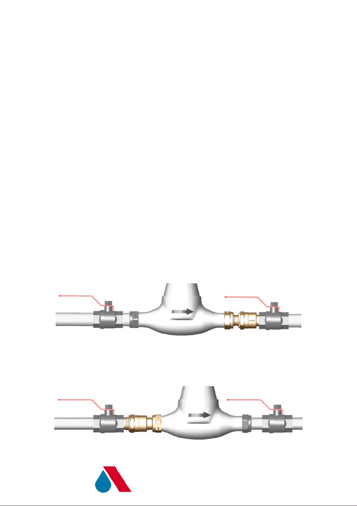
Figure 1 Connection of UFR with union nut connection, downstream of the wate r meter.
Figure 2 – Connection of UFR with union nut connection, upstream of the water meter.
A.R.I FLOW CONTROL ACCESSORIES
WWW.ARIVALVES.COM
Page 2
2. Installation of the UFR with threaded male or female connections directly into the
piping:
A. Close the shut off valves upstream and downstream of the region that the
UFR is to be installed.
B. Match the direction of the arrow on the UFR with the normal direction of
water flow in the piping.
C. Connect the UFR with threaded male or female connections, or to the piping
or shut off valve or water meter coupling. Use sealants that are generally
used in potable water systems.
D. Open the shut off valves upstream and downstream and check for seal
tightness.
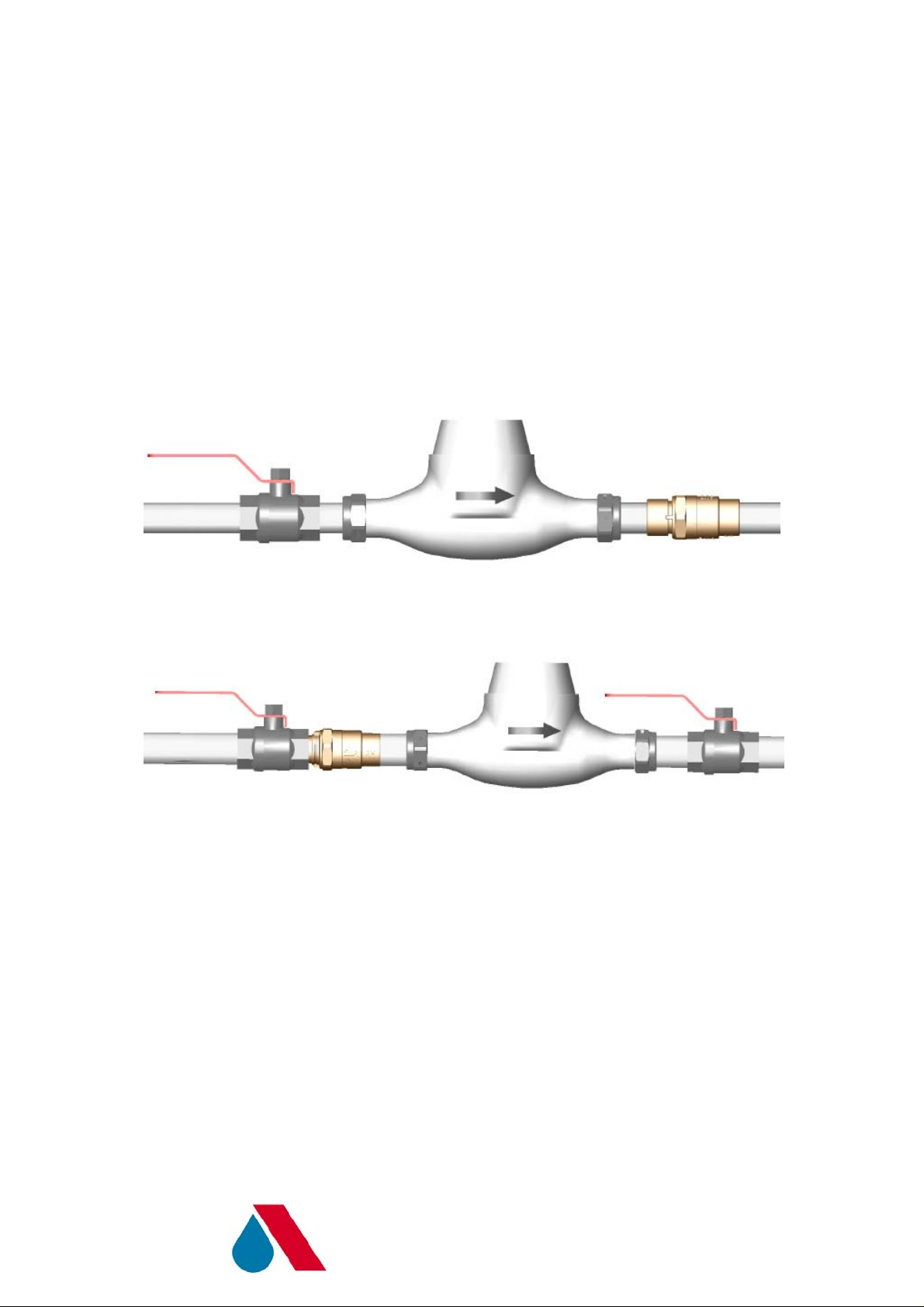
Figure 3 – Connection of UFR with threaded male or female connections, downstream of the
water meter.
Figure 4 – Connection of UFR with threaded male or female connections, upstream of the
water meter directly to the shut off valve and water meter coupling.
Prevention of malfunctions in the product during installation:
1. Rinse the pipe that you intend to attach the UFR to, in order to prevent large bodies
from entering the UFR.
2. Make sure not to let any sealant enter the UFR, especially the sealing region inside
the UFR.
3. Make sure to tighten the UFR using an appropriate wrench on the hexagon flats only.
A.R.I FLOW CONTROL ACCESSORIES
WWW.ARIVALVES.COM
Page 3

Troubleshooting:
Problem Possible causes Solutions.
No flow in the line 1. Shut off valves have not
been opened after
installation.
2. The product is installed
the wrong way round
(against the flow
direction).
3. Mains pressure is less
than 1 bar.
There is a leak in the house
but the UFR is not working.
Leak between the two parts
of the UFR
1. There is a lot of air in the
system following the
installation.
2. The leak in the house is
more than 30 liters per
hour (cumulative).
3. Sealant has entered the
sealing area of the UFR.
The UFR has opened up and
the O-ring no longer seals.
1. Check shut off valves.
2. Check direction of the
product, and if necessary
invert it in accordance
with the flow direction.
3. The UFR requires a
minimum mains pressure
of 1 bar to work normally.
1. Purge air from the
system by opening the
taps in the house and
check again.
2. At more than 30 liters per
hour, the UFR stops
working, so there is no
problem.
3. Remove the UFR from
the line and clean out the
sealant.
Tighten the two parts of the
UFR, open the water
pressure again, and check
for leaks.
A.R.I FLOW CONTROL ACCESSORIES
WWW.ARIVALVES.COM
 Loading...