

Page 1
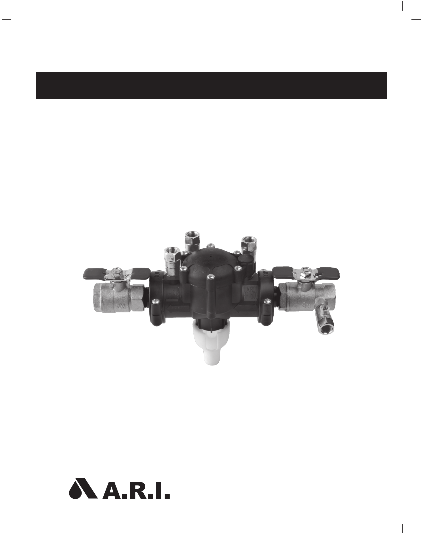
RP-500 Reduced Pressure Backfl ow Preventer
OPERATIONS, MAINTENANCE AND
TROUBLESHOOTING GUIDE
Page 2

2 • RP-500 Operations, Maintenance and Troubleshooting Guide A.R.I.
Table of Contents
Features, Applications and Specifi cations ..........................................................................3
Installation ..............................................................................................................................4
Operation ................................................................................................................................5
Testing Procedures ................................................................................................................6
Maintenance ...........................................................................................................................8
Troubleshooting Guide.........................................................................................................9
Replacement Parts List .......................................................................................................10
Page 3
RP-500 Operations, Maintenance and Troubleshooting Guide A.R.I. • 3
The RP-500 Reduced Pressure Backfl ow Preventer consists of:
• Two independent-acting spring-loaded check valves - an inlet and an outlet valve.
• An automatic differential Relief Valve (located in the “zone” between the check valves) .
• Two resilient seated shut off valves – one on the inlet, the other on the outlet.
• Four test cocks.
PRODUCT FEATURES
• Compact, lightweight size makes it easy and quick to install.
• Requires only a Phillips-head screwdriver to disassemble and reassemble – no special tools needed .
• Durable, made of non-corrosive plastic thermal resin material:
- Withstands the toughest environments.
- Unlike a brass Backfl ow Preventer, the RP-500 is less susceptible to vandalism and theft.
- UV resistant – endures heat and direct sun.
• Low head loss – optimizes energy, saving energy costs.
The RP-500 is approved by the following Standards Authorities:
Approved under :
USA : NSF61 (Drinking water), ASSE 1013, AWWA C511, Approved by the Foundation for Cross
Connection Control and Hydraulic Research at the University of Southern California, Listed for Uniform
Plumbing Code.
Australia : AS4020 (Drinking water), Watermark AS2845.1.
France : ACS.
APPLICATIONS
To protect potable water lines and other installations against backsiphonage and backpressure of
contaminated water.
For irrigation system and water handling applications.
SPECIFICATIONS
• Operating pressure: up to 150 psi
• Operating temperature: up to 110º F
• Valve sizes: ½”, ¾”, 1”, 1¼”, 1½”, 2”
Features, Applications and Specifi cations
Page 4
4 • RP-500 Operations, Maintenance and Troubleshooting Guide A.R.I.
Installation
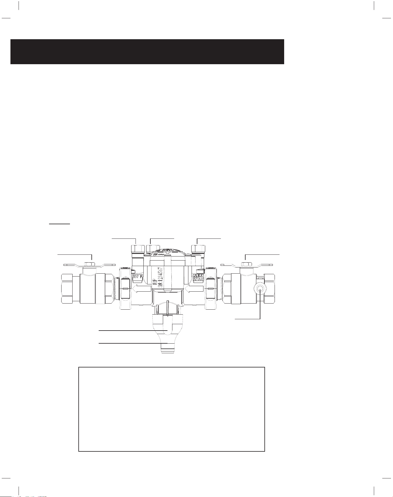
FIGURE 1
GENERAL INSTALLATION GUIDELINES
A. Install the RP-500 Backfl ow Preventer in a location accessible to periodic fi eld testing and
maintenance. Mount the RP-500 in a horizontal position with adequate clearance from walls and/
or obstructions. A 12” to 33” clearance is needed between the lowest portion of the device and
fl oor.
B. Adequate drainage is needed for discharge. A Drainage Funnel is provided so the discharge may
be piped away (See FIGURE 1).
NOTE: Never place the RP-500 where it may become submerged in standing water.
C. Before installing the RP-500, thoroughly fl ush all upstream piping to remove debris.
D. When the shut-off valves are supplied separately, install them with a Test Cock on the Inlet Shut-
off Valve.
E. It is recommended that a “Y” strainer be installed before the inlet of the RP-500 to prevent debris
from entering the device.
F. After installing the assembly, close the Outlet Shut-off Valve, pressurize the RP-500 and release the
air through Test Cock 4. Then, open the Outlet Shut-off Valve.
RECOMMENDATIONS
• Do not install in areas subject to extended periods of freezing
temperatures.
• The product must be protected from excessive pressure increases,
caused by thermal expansion or water hammer, which can cause
damage to the valve.
• DO NOT USE ANY PIPE DOPE, OIL, GREASE OR SOLVENT
ON ANY PARTS unless instructed to do so.
• Parts should fi t together freely. Do not force parts to fi t.
2XWOHW6KXW2II9DOYH
7HVW&RFN 7HVW&RFN 7HVW&RFN
7HVW&RFN
,QOHW6KXW2II9DOYH
'UDLQDJH)XQQHO$LU*DS
'UDLQDJH)XQQHO
Page 5

RP-500 Operations, Maintenance and Troubleshooting Guide A.R.I. • 5
Operation
FIGURE 2
During normal fl ow, the two check valves open to supply water downstream. The Relief Valve is power-
activated by upstream pressure and is kept shut by a diaphragm, through the internal control system.
In the zone, the area between the check valves, pressure is maintained at approximately 6.3 psi lower than
the water supply pressure. The Outlet Check Valve is spring-loaded to maintain a minimum pressure
decrease of 1 psi (see FIGURE 2).
When negative pressure or sub-atmospheric conditions occur, the Inlet Check Valve closes to prevent
backfl ow. If the Outlet Check Valve fails, the pressure between the two check valves rises, opening the
Relief Valve and releasing the water to the atmosphere.
The Relief Valve operates on differential pressure. Supply pressure on the upstream side of the Inlet
Check Valve acts against the diaphragm to close the Relief Valve during normal operation. In the event of
backpressure or backsiphonage, the Relief Valve will open to maintain the pressure in the “zone” at 2 psi
less than the inlet pressure.
Note: If water continues to drain from the Relief Valve, check the
Troubleshooting section for probable causes and solutions.
2XWOHW6KXW2II9DOYH
,QOHW6KXW2II9DOYH
,QOHW&KHFN9DOYH
6SULQJORDGHG
2XWOHW&KHFN9DOYH
6SULQJORDGHG
5HOLHI9DOYH
5HOLHI9DOYH
6HDW6HDO
,QOHW6KXW2II9DOYH
=RRQ
Page 6

6 • RP-500 Operations, Maintenance and Troubleshooting Guide A.R.I.
Testing Procedures
To remain in compliance with local codes it is important to periodically test the RP- 500. (As service
conditions warrant, it should be tested at least once per year or more.) Test set-up is illustrated in FIGURE
3 on page 7.
Equipment: USC approved test kit required.
Test No. 1
Purpose: To test operation of the pressure differential Relief Valve.
Requirement: The pressure differential Relief Valve must operate to maintain a minimum pressure of 2
psi less than the supply pressure in the “zone” (the area between the two Check Valves).
Procedure (see FIGURE 3, page 7):
1. To fl ush debris, release the water through all four Test Cocks.
NOTE: Open Test Cock 2 slowly to avoid accidental dumping of the Relief Valve.
2. Connect the “high” side (gray) hose to check Test Cock 2.
Connect the “low” side (yellow) hose to check Test Cock 3.
3. Open Test Valves 2 and 3.
4. Slowly open Test Cock 3 and release all air from the gauge and hoses through the “vent (red) hose. While
Test Cock 3 is open, slowly open Test Cock 2 and release all air again through the “vent” (red) hose.
Close Test Valve 3, and then close Test Valve 2.
5. Close Outlet Shut-off Valve.
6. Slowly open Test Valve 3 until the differential gauge starts to drop.
NOTE: It is important that the differential gauge drops slowly. To do so, maintain Test
Valve 3 at this position and observe the differential pressure reading at the moment the fi rst
discharge is noted from the Relief Valve.
7. Record this reading as the opening differential pressure of the Relief Valve and close Test Valve 3.
Test No. 2
Purpose: To check Outlet Check Valve for tightness against reverse fl ow.
Requirement: The Check Valve should not allow through leakage in a direction opposite to normal fl ow
under all conditions of a pressure differential.
Procedure (See FIGUR 3, page7):
1. The Outlet Shut-off Valve should be in the closed position (from Test 1).
2. Loosely attach the “vent” (red) hose to Test Cock 4.
3. Release all air from the “vent” (red) hose by opening Test Valve 2.
4. Close Test Valve 2 and tighten hose connection to Test Cock 4. Then open Test Cock 4.
5. Loosen the “low” side (yellow) hose at Test Cock 3 slightly and re-establish the normal reduced pressure
within the zone. Retighten hose.
6. Open Test Valve 2
If the differential pressure remains steady then the Outlet Check Valve is working properly. If the differential
pressure drops causing the Relief Valve to open, then Outlet Check Valve should be recorded as “leaking”
and Test 3 cannot be completed.
Page 7

RP-500 Operations, Maintenance and Troubleshooting Guide A.R.I. • 7
Testing Procedures, cont.
FIGURE 3
Test No. 3
Purpose: To test the static differential pressure across the Inlet Check Valve.
Requirement: The static differential pressure across Inlet Check Valve must be a minimum of 3 psi more than
the opening differential pressure of the Relief Valves as recorded in Test 1.
Procedure (See FIGURE 3):
With the testing equipment installed as stated in Test 2, the static differential pressure across the Inlet Check
Valve will be indicated on the gauge and should be recorded as such.
NOTE: The gauge should be steady and not falling.
Restore Operation (See FIGURE 3): Close all Test Cocks, open all Test Valves, open the Outlet Shut-off Valve
and carefully remove all test equipment.
NOTE: Refer to Troubleshooting Guide to resolve any problems incurred during fi eld-testing.
2XWOHW6KXW2II9DOYH
7HVW&RFN
*DXJH
7HVW&RFN
7HVW&RFN
7HVW&RFN
,QOHW&KHFN9DOYH
,QOHW6KXW2II9DOYH
2XWOHW&KHFN9DOYH
7HVW9DOYH
/RZ6LGH+RVH\HOORZ +LJK6LGH+RVHJUD\
7HVW9DOYH
7HVW9DOYH
K\GUDXOLF+RVH
7HVW9DOYH
Page 8

8 • RP-500 Operations, Maintenance and Troubleshooting Guide A.R.I.
1
1.1
9
9
8
2
3
4
7
6
5
12
11
10
10
13
Maintenance
How to Disassemble the RP-500
1. Close the Outlet Shut-off Valve (12), then close Inlet Shut-off Valve (11).
2. Release pressure from the assembly by opening Test Cocks 2, 3 and 4 (8).
CAUTION: The cover is spring-loaded and should be removed carefully to avoid personal injury.
3. Use a Phillips-head screwdriver to remove the Relief Valve cover screws (1.1) while holding the cover
(1) down.
4. Lift the cover (1) straight up.
5. Remove the Relief Valve Assembly (3).
6. Remove the Relief Valve Spring (4).
7. Remove the Retainer (5).
8. Remove the Inlet and Outlet Check Valves (6) (7).
NOTE: Clean all the parts that have been removed. Then reassemble, or depending on their
condition, discard and replace with new replacement parts. O-rings should be cleaned or replaced
as necessary and lightly greased with NSF 61-approved silicone-based grease.
How to Assemble the RP-500
1. Securely install the Inlet and Outlet Check Valves (6) (7).
2. Install the Retainer (5).
3. Place the Relief Valve Spring (4) in position.
4. Install the Relief Valve Assembly (3).
5. Put on the cover (1), hold it down and tighten the screws (1.1).
CAUTION:
RP-500 ½”, ¾”, 1” Secure the screws with a recommended torque of 1.84 pound force feet (2.5 Nm).
RP-500 1 ¼”,1 ½”, 2” Secure the screws with a recommended torque of 6.64 pound force feet (9 Nm).
Part List
No. Part
1. Cover Assembly
1.1 Cover Screws
2. Relief Valve Assembly
3. Relief Valve Spring
4. Retainer
5. Inlet Check Valve Assembly
6. Outlet Check Valve Assembly
7. Body Assembly
8. Test Cocks (#1, #2, #3, #4)
9. Adaptor Assembly
10. Clamp Assembly
11. Inlet Shut-off Valve
12. Outlet Shut-off Valve
13. Drainage Funnel
Page 9

RP-500 Operations, Maintenance and Troubleshooting Guide A.R.I. • 9
Troubleshooting Guide
SYMPTOM CAUSE SOLUTION
Relief Valve continuously discharges
during no-fl ow settings..
A. Inlet Check Valve (٥) is fouled
with debris.
A. Inspect and clean the seat and seal.
B. Outlet Check Valve (٦) is
fouled with debris coupled with a
backpressure condition.
B. Inspect and clean the seat and seal.
Relief Valve continuously discharges
during fl ow and no-fl ow settings.
A. Relief Valve fouled with debris. A. Clean Relief Valve Assembly (2).
B. Damaged diaphragm (allows water
to pass through, from inlet to zone).
B. Replace the Relief Valve Assembly (2).
C. The passage to inlet side of
diaphragm plugged.
C. Inspect and clean the passage in the
Cover (1) and the Body (2).
Relief Valve does not open during
fi eld test no.1
A. Outlet Shut-off Valve (12) is not
closed completely.
A. Close Outlet Shut-off Valve (12) or
inspect for possible through leakage.
B Test equipment improperly
installed.
B. Recheck test procedure.
Inlet Check Valve (5) does not hold
backpressure.
A. Outlet Shut-off Valve (12) is not
closed completely.
A. Close Shut-off Valve (12) or inspect
for possible through leakage.
B. Outlet Check Valve (6) is fouled
with debris.
B. Inspect and clean the seat and seal.
Pressure differential is low across
the Inlet Check Valve (5) during
Field Test 3 (Does not meet 3 PSID
minimum).
A. Check Valve (6) is fouled with
debris.
A. Inspect and clean the seat and seal.
B. Upstream pressure fl uctuations
causing inaccurate gauge reading.
B. Eliminate pressure fl uctuation.
Page 10

10 • RP-500 Operations, Maintenance and Troubleshooting Guide A.R.I.
Replacement Parts List
MODELS ½”, ¾”, 1” MODELS 1¼”, 1½”, 2”
PART CATALOG NO. QNT CATALOG NO. QNT
1. Cover Assembly 0466-0501-KIT 1 0465-0502-KIT 1
2. Relief Valve Assembly 0466-9601 1 0466-9602 1
3. Relief Valve Spring 0266-7696 1 0266-769602S2 1
4. Retainer 0266-3101 1 0266-3102AN 1
5. Inlet Check Vakve Assembly 0466-0276-IN 1 0465-027602-IN 1
6. Outlet Check Valve Assembly 0466-0276-OUT 1 0466-027602-OUT 1
7. Adaptor Assembly
1/2” NPT 1¼” NPT 0466-4850BT-KIT 2 0466-48114NT-KIT 2
3/4” NPT 1½” NPT 0466-4834BT-KIT 2 0466-48112NT-KIT 2
1” NPT 2” NPT 0466-4801BT-KIT 2 0466-4802NT-KIT 2
8. Clamp Assembly 0466-99-KIT 2 0466-9902-KIT 2
9. Inlet Shut Off Valve 0310-7301NTBQ-FFFBFH 1 0310-7302NTBQ-FFFBFH 1
10. Outlet Shut Off Valve 0310-7301NTBQ-FF-BFH 1 0310-7302NTBQ-FF-BFH 1
11. Drainage Funnel 0266-5101 1 0266-5102AN 1
Page 11

RP-500 Operations, Maintenance and Troubleshooting Guide A.R.I. • 11
Replacement Parts List
1
8
8
9
2
3
4
7
7
6
5
11
10
Page 12

A.R.I. USA, Inc. www.arivalves.com Tel: 559-246-7585
e-mail: ron@ari.co.il Tel: 877-536-6201
0302-USMB-RP500-10
 Loading...