

Page 1
MAINTENANCE INSTRUCTIONS
COMBINATION AIR VALVE
MODEL D-070-P
GENERAL
1. The periodic maintenance of the air valve is an integral part in the proper
regimen of water pipeline maintenance.
2. The air valve should be maintained at least once a year in accordance with the
quality of the water and the types of uid composition in the system.
INSTALLATION
Before installing the Model D-070-P air valve, make sure to ush and drain the
pipeline of all dirt and solids that may be in the line.
Installation of an isolating valve: An isolating valve will be installed under each
air valve to enable the performance of periodic maintenance.
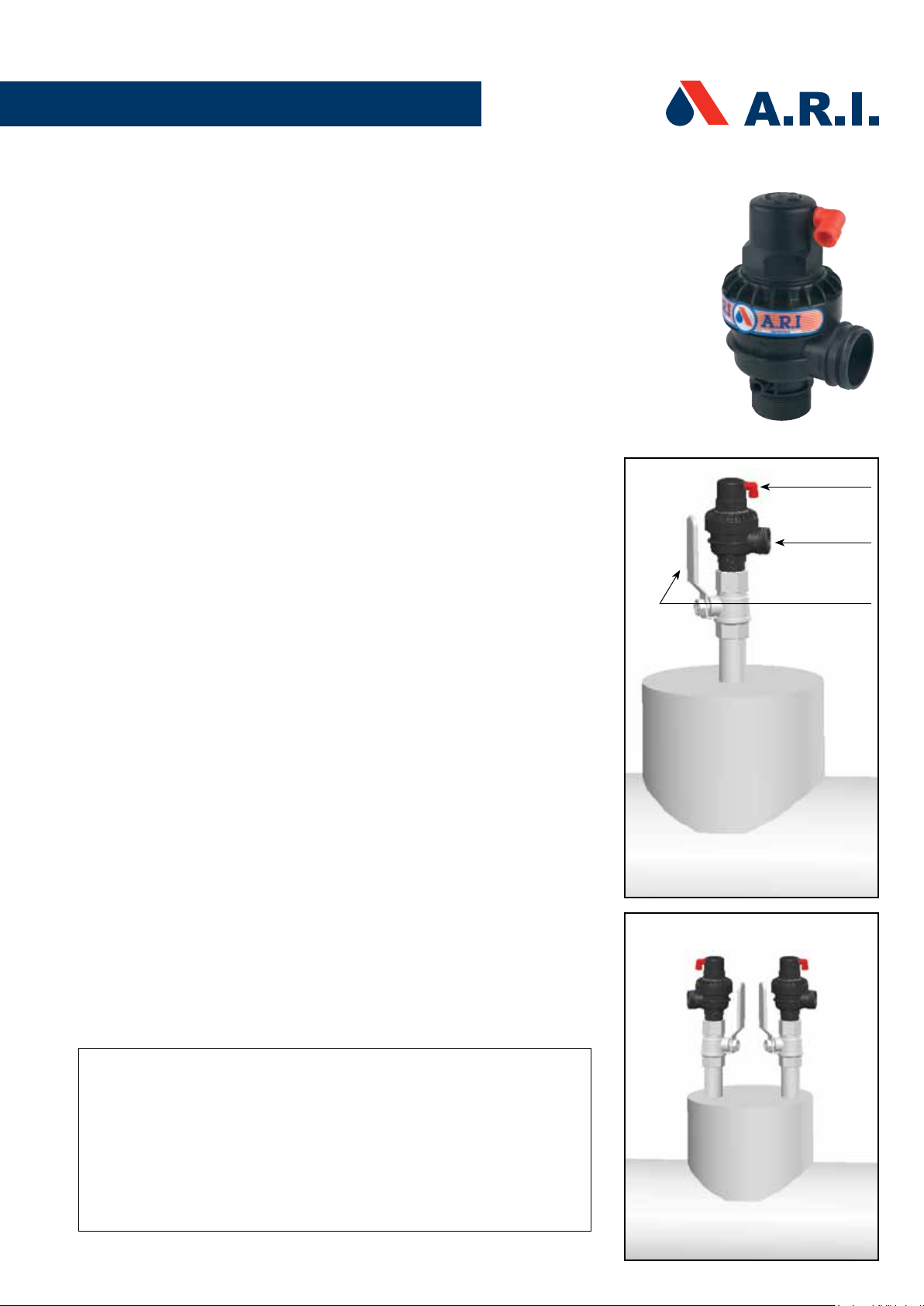
Installation of a riser: It is recommended to install the Model D-070-P air valve
on top of a riser (see Fig.1). Diameter of the riser should be at least one-half the
diameter of the pipeline.
Manifold: When the valve is installed on a manifold, the air valves should be
installed only on a welded manifold. They should be installed in a manner that the
drainage port openings should face in opposite directions (see Fig.2).
DRAIN PORT
1. Drainage angle: It is recommended installing a drainage angle at the drain
port (#1) exit; the diameter of the drainage angle should be at least the
diameter of the drain port.
2. Maintain an open drain port: Do not seal or block the opening of the valve
drain port (#1).
3. Warning on emission of water: The normal operation of the valve includes
water emissions under pressure. Ensure that the drain port (#1) is not
directed toward electrical elements (pumps) or people.
4. Caution: Do not put hands or objects into the drainage port (#1).
5. Drainage Pipe: Drainage pipes, at least 2" in diameter with a maximum
length of 9m, can be connected to the drainage angle to direct the emission
water. The end of the drainage pipe should remain completely open and
unobstructed. Do not connect a drainage pipe to the upper drainage port
(#2).
Drain Port #2
Drain Port #1
Isolating valve
Fig. 1
WARNING
Perform the following operations prior to maintenance or removal of the air
valve from the pipeline:
1. Shut the isolating valve (Fig.1) on the riser below the air valve.
2. Slowly open the Locking Ring (6) until water and air start to be released. Wait
until all the water and air cease to be released before continuing
3. Continue to open the Locking Ring (6) slowly; making sure that the pressure
has been released from inside the air valve prior to maintenance/removal
from the pipeline.
Fig. 2
Page 2
PERIODIC MAINTENANCE
The purpose of periodic maintenance: check integrity of the seals and clean the
sealing areas.
The frequency of maintenance will be determined by the condition of the water
system – weekly, monthly, quarterly etc.
The maintenance of the Dynamic Air Valve is performed for 2 separate parts:
MAINTENANCE OF THE OPERATING VALVE
1. Shut the isolating valve on the riser below the air valve.
2. Unscrew the Operating Valve Body (2).
3. Remove the Clamping Stem (4) and the Operating Assembly (5). Wash the
inside of the Body , the Clamping Stem , the Operating Assembly , the
Rolling Seal (3), and the O-ring (7) with clean water.
4. Gently wash and clean the sealing area inside the valve body.
5. Check the O-Ring visually for any defects. Replace if needed.
6. Check and make sure that the Rolling Seal is intact (not torn or cracked)
and is positioned precisely in the middle of its groove in the Operating
Assembly. Replace if needed.
7. The disc at the bottom of the Operating Assembly (Fig. 4) should be loose
and move freely. Do not tighten the holding screw.
8. Reassemble the Operating Valve after maintenance.
MAINTENANCE OF THE DYNAMIC VALVE BODY
9. Unscrew and remove the Locking Ring (6) together with the attached
Operating Valve. Remove the Air & Vacuum Sealing Assembly (9) from the
Body (11).
10. Wash the Body and the Locking Ring in clean water in order to remove
coarse grime or accumulated scale.
11. Wash the Air & Vacuum Sealing Assembly and check the rubber parts for
any tears. Replace the entire unit if needed.
Do not open screws of the assembly under any circumstances.
12. Make sure that the drill hole is clean and the passage is open (Figure 5).
13. Make sure that there is no dirt or debris around the sealing area of the
dynamic valve body.
14. Replace the assembly in the body, reassemble in reverse order, then fasten
and tighten the Locking Ring.
15. Open the isolating valve beneath the air valve, making sure that there are
no leaks.
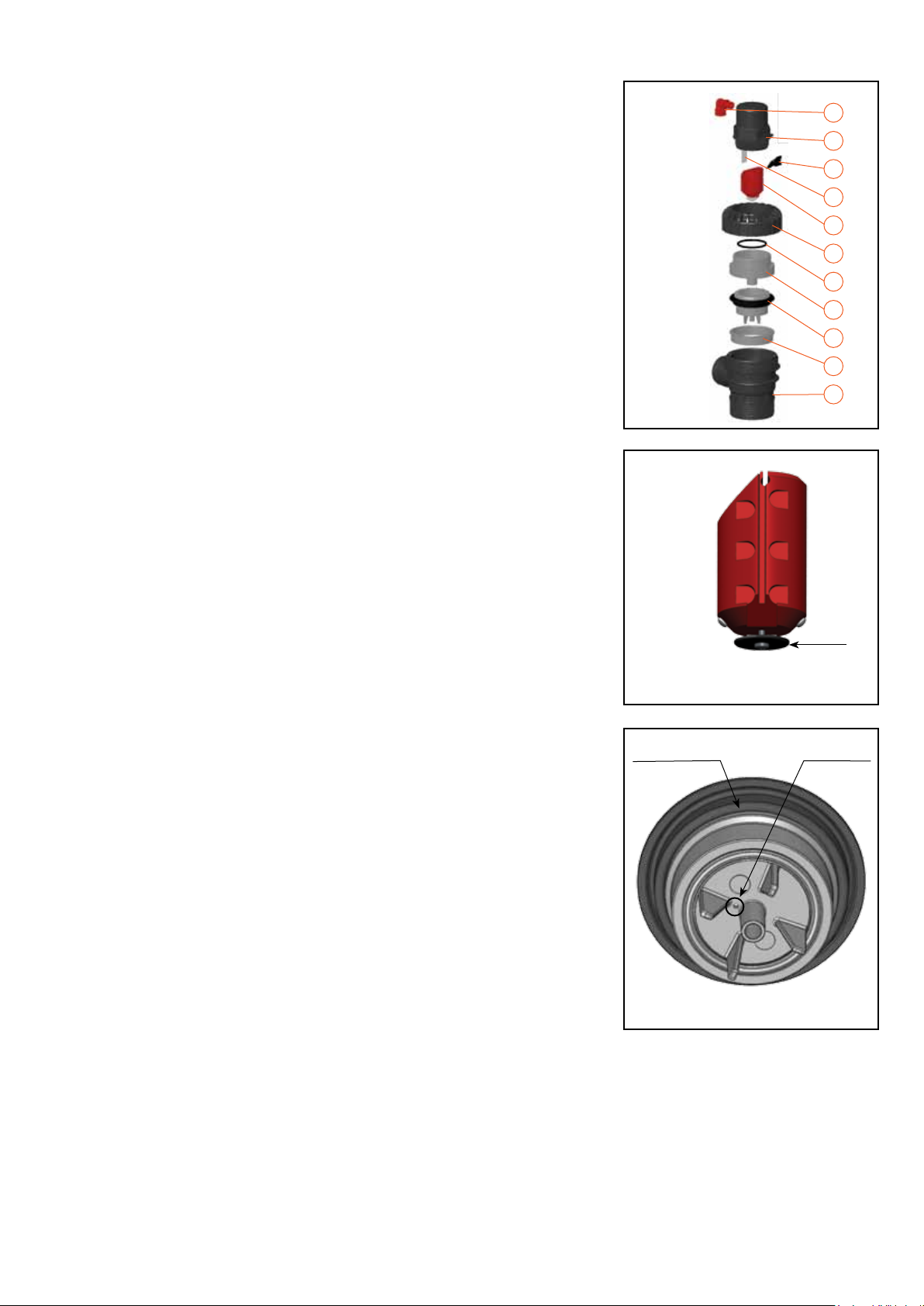
1
2
3
4
5
6
7
8
9
10
11
Fig. 3
Disc
Fig. 4 Operating Assembly
Sealing Assembly Drill Hole
FIg. 5
Air & Vacuum Sealing Assembly
Page 3

No. Part
1. Discharge Outlet
2. Operating Valve Body
3. Rolling Seal
4. Clamping Stem
5. Operating Assembly
6. Locking Ring
7. O-Ring
8. Base Adaptor
9. Air & Vacuum Sealing Ass.
10. Supporting Ring
11. Body
TROUBLESHOOTING GUIDE
PROBLEM REASON SOLUTION
1
2
3
4
5
6
7
8
9
10
11
Fig. 3
1.
Leaking from the
Drain Port #2
(Fig 1).
2.1.
Leaking from the
Drain Port #1
(Fig 1).
2.2.
Leaking from the
Drain Port #1
(Fig 1).
Debris or scale
build-up on the
rolling seal (5).
Debris or
unwanted object
caught in the air
& vacuum sealing
assembly. (11)
Torn sealing
assembly or
diaphragm. (11)
1. Shut off the isolating valve on the riser below the air valve.
2. Unscrew the operating valve body. (2).
3. Remove the clamping stem (4) and the operating assembly (5). Wash the
inside of the body, the clamping stem, the operating assembly, the rolling
seal (3), and the O-ring (7) with clean water.
4. Gently wash and clean the sealing area inside the valve body.
5. Check the O-ring visually for any defects. Replace if needed.
6. Check and make sure that the rolling seal (3) is intact (not torn or cracked)
and is positioned precisely in the middle of its groove in the operating
assembly. Replace if needed. The disc at the bottom of the operating
assembly (5) should be loose and move freely.
Do not tighten the holding screw.
7. Reassemble the Operating Valve after maintenance.
1. Shut off the isolating valve on the riser below the air valve.
2. Unscrew and remove the locking ring (6)together with the attached
operating valve.
3. Remove the air & vacuum sealing assembly (9) from the body (11).
4. Wash the body (14) and the locking ring in clean water in order to remove
coarse grime or accumulated scale.
5. Wash the air & vacuum sealing assembly (9) and check the rubber parts for
any tears.
6. Make sure that the drill hole (Fig. 5) is clean and the passage is open.
7. Make sure the air & vacuum assembly seal is intact and not torn.
8. Replace the whole air & vacuum assembly if any of the above parts are torn
or damaged.
9. Do not open screws of the assembly under any circumstances.
10. Make sure that there is no dirt or debris around the sealing area of the
dynamic valve body.
11. Replace the assembly in the body, reassemble in reverse order, then fasten
and tighten the locking ring.
12. Open the isolating valve beneath the air valve, making sure that there are no
leaks.
A.R.I. FLOW CONTROL ACCESSORIES Ltd.
www.arivalves.com ari@ari.co.il Tel: 972-4-6761899
MAINTENANCE INSTRUCTIONS D-070-P
EnM-D070-P-11
 Loading...