

Page 1
Handeling , Installation , Operation and
Maintenance instructions for
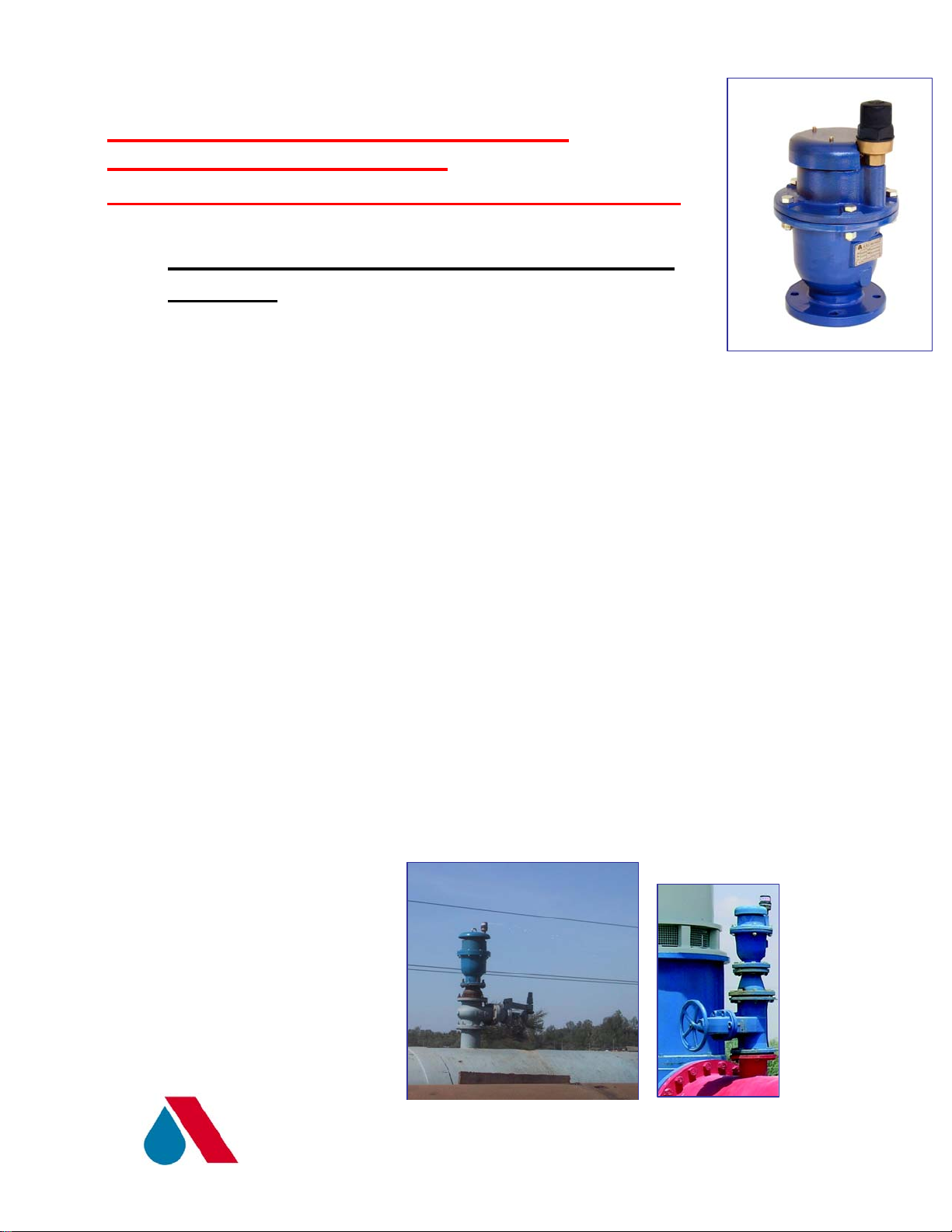
D-060 HF NS Combination Air Valves Non
Slam
A. Installing and Operating the D060 HF-NS
Air valve
B.1. The air valve will be mounted on a riser, connected to the top
of the pipe.
B.2. An isolating valve will be installed below the airvalve.
B.3. Flush the system before installing the air valve to avoid any
dirt or sharp objects getting into the air valve.
B.4. Lift the air valve from the lifting ring by a hoke place
it carfuly on the rubber seal over the shut-off valve.
B.5. Use washers below each bolt & nut that connects the air
valve’s flange to the shut-off valve below.
B.6. The bolts and nuts should be tighten simultanicly (one
Against the other (opposite to him).
The closure tightness of bolts and nuts shall be according
to the standard (Torque) for the bolts and nuts dimention
is used .
Please use ring ranch keys (to be operated by hand) for
closing and opening all bolts of the air valve (inclu. The bolts
at the flage).
A.R.I FLOW CONTROL ACCESSORIES LTD
Page 2
B. Maintening the D060 HF-NS Ai
r valve
.Maintening the Automatic air valve. 1.C
C.1.1. Shutoff the isolating valve below the air valve
C.1.2. Unscrew the body (1)of the Automatic air valve
(No.22
drawing no. 5292-00-02) from the Base (make sure
that the base will not rotate!).
C.1.3. Remove the Clamping Stem (3)and the float (4)from
the automatiic component and wash the inside
of the body, the Clamping Stem, the float, and
the Rolling Seal (2),with clean water.
C.1.4.
Check to make sure that the Rolling Seal is unharmed
(not torn or cracked) and is located precisely in the
middle of its groove in the float.
.
C.1.5. Reassemble the air valve in the opposite order:
First insert half the lengh of the roaling seal tail
into the track (grrove) in the body, then push
the rest of the way to the end of the groove ,
using the clamp.Make sure that the
roalling seal is set and hold inits place.
A.R.I FLOW CONTROL ACCESSORIES LTD
Page 3

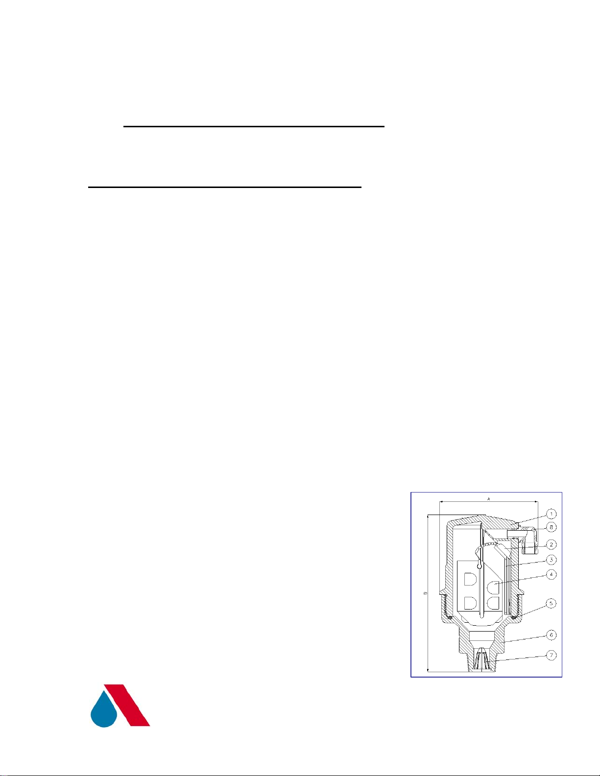
.Maintening the Kinetic air valve2 .C
C.2.1. Unscrew the bolts (8) that connect the valve cover (2)
to its body (1).
C.2.2. Clean the internals of the following parts part :
the body including the groove of the Oring , the screen,
the float and the cover with clean water in order to remove
coarse grime or accumulated scale.
C.2.3. Check that the nozzle seal (4) is in a good shap , means
that is not torn and/or not cracked.
C.2..4. In case that the nozzle seal is in a bad condition, please
Remove the nozzle seat + seal (3+4) witout harming
the coating, than clean carefuly the cover seat
of the reamined glue, rub into the seat Epoxy glue and
push the nozzle seat and seal into the its place in the cover.
Wait for minimum 24 hours for the glue to get dried
completely.
C.2.5. Reassemble the air valve in the opposite order:
insert the float, than place the Oring in the groove,
place the cover on the body, insert the botls ,
the washers and the screw the nuts and the washers on
the nuts.
C.2..6. The bolts and nuts should be tighten simultanicly
(one against the other opposite to him).
The closure tightness of bolts and nuts shall be according
to the standard (Torque) for the bolts and nuts dimention
is used .
Please use ring ranch keys (to be operated by hand) for
closing and opening all bolts of the air valve.
A.R.I FLOW CONTROL ACCESSORIES LTD
Page 4

.Shock element-Maintening the Anti3 .C
C.3..1. Please check (through the cover) that the flap (18) moves
Freely without any distturb in the falp house (17).
C.3.2. In case that the flap does not move freely in the flap house,
Please act as follows:
C.3.3. Unsrew the four domed nuts (12) , take of the screen
Cover (6) and the screen (7).
C.3.4. Unscrew the nuts (13) of the four threaded rods.
C.3..5.Take of the ring K060NS.
C.3.6. Pull out the flap of the house.
C.3.7. Clean the flap house and the flap in order to remove
coarse grime or accumulated scale.
C.3.8. Reassemble the Anti- Shock element in the opposite order:
insert the flap into the flap house, than place the ring
K060HF-NS through the threade rods , screw the nuts
on the four threade rods and close it tightly. Place the
screen over the K060HF-NS ring , than screw the nuts
on the four threade rods .
Place the screen cover over the nuts , add the four
domed nuts over the screen cover and close it tightly
to the screen cover.
A.R.I FLOW CONTROL ACCESSORIES LTD
 Loading...