

Page 1
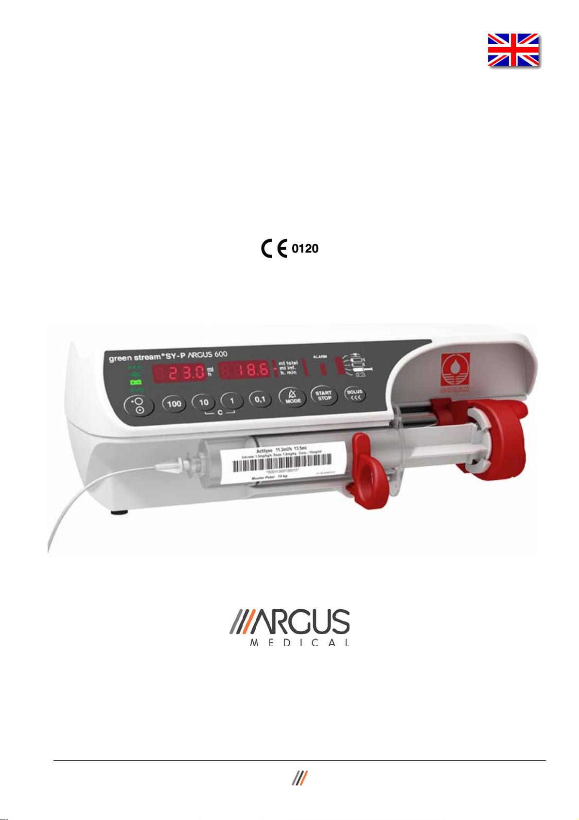
Service Manual for Syringe Pump
ARGUS 600 S
Made in Switzerland
ARGUS Medical AG, CH-3627 Heimberg / Switzerland
(a member of the CODAN group)
14.194.A_A600 en.SM.V4.3X ARGUS Medical AG 28.03.06 / PJ 1 / 47
Page 2

INTRODUCTION
TABLE OF CONTENTS
1. INTRODUCTION ...............................................................................................................5
1.1. General .................................................................................................................................. 5
2. PUMP CONFIGURATIONS...............................................................................................5
2.1. General .................................................................................................................................. 5
2.2. Interrogation mode (without ARGUS service)........................................................................ 6
2.3. Configuration mode (without ARGUS service) ...................................................................... 7
2.4. First activation of a PIN Code (write protection) .................................................................... 8
2.5. Changing an existing PIN code .............................................................................................9
2.6. Address list of the pump configuration (without ARGUS service)........................................ 10
2.7. Index list of the pump configuration (with ARGUS service) ................................................. 11
2.8. User syringe......................................................................................................................... 14
2.9. Medication list ...................................................................................................................... 15
3. Serial communication of the pump..............................................................................17
3.1. General ................................................................................................................................ 17
3.2. Serial communication protocol.............................................................................................17
4. ARGUS service...............................................................................................................18
4.1. General ................................................................................................................................ 18
4.2. ARGUS service – Configuration .......................................................................................... 19
4.3. ARGUS service - Toolbox.................................................................................................... 20
5. SOFTWARE UPDATES .................................................................................................. 24
5.1. General ................................................................................................................................ 24
5.2. Requirements for a software update.................................................................................... 24
5.3. Software update procedure .................................................................................................24
5.4. Safety aspects ..................................................................................................................... 26
6. MAINTENANCE ..............................................................................................................27
6.1. General ................................................................................................................................ 27
6.2. Recalibration........................................................................................................................ 27
6.3. Final calibration.................................................................................................................... 28
6.4. Pressure control and pump accuracy measurement ........................................................... 34
6.5. Rough alignments................................................................................................................ 35
6.6. Battery capacity calibration.................................................................................................. 37
6.7. Pump specifications............................................................................................................. 37
6.8. Fault codes and "CtrL" message ......................................................................................... 38
7. REPLACEMENT OF PARTS .......................................................................................... 39
7.1. General ................................................................................................................................ 39
7.2. Spare parts .......................................................................................................................... 41
8. WIRING DIAGRAMM ......................................................................................................44
9. BLOC SCHEMATIC ........................................................................................................45
10. SAFETY STANDARD CHECK........................................................................................46
11. REPAIR ORDER FORM..................................................................................................47
14.194.A_A600 en.SM.V4.3X ARGUS Medical AG 28.03.06 / PJ 2 / 47
Page 3
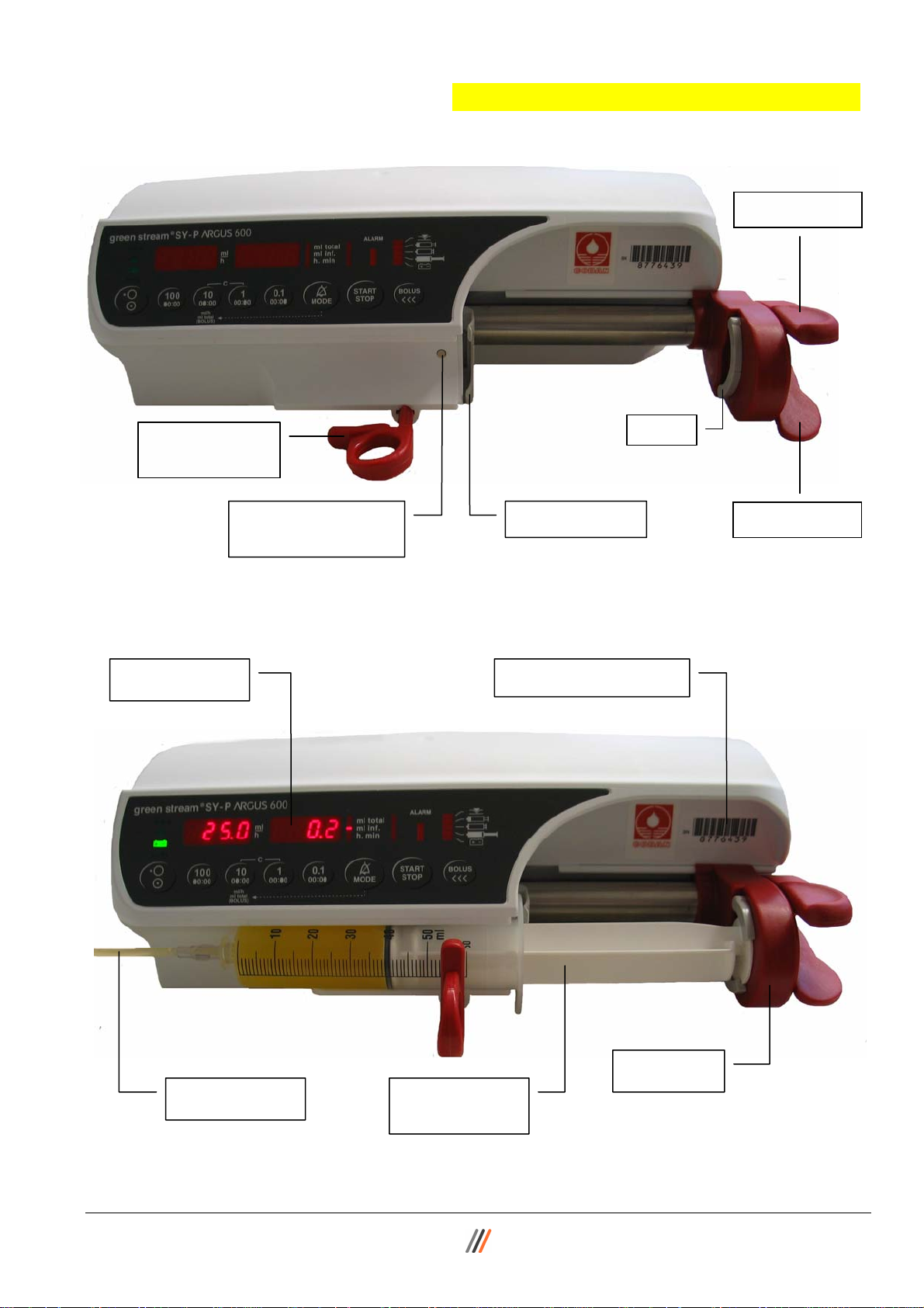
INTRODUCTION
Clutch lever
Syringe barrel
Beak
holder
pushbutton switch
Syringe guide Syringe presence
Clamp lever
Display panel
Pump serial number
Extension line
Syringes from
10 – 60 ml
Drive unit
14.194.A_A600 en.SM.V4.3X ARGUS Medical AG 28.03.06 / PJ 3 / 47
Page 4
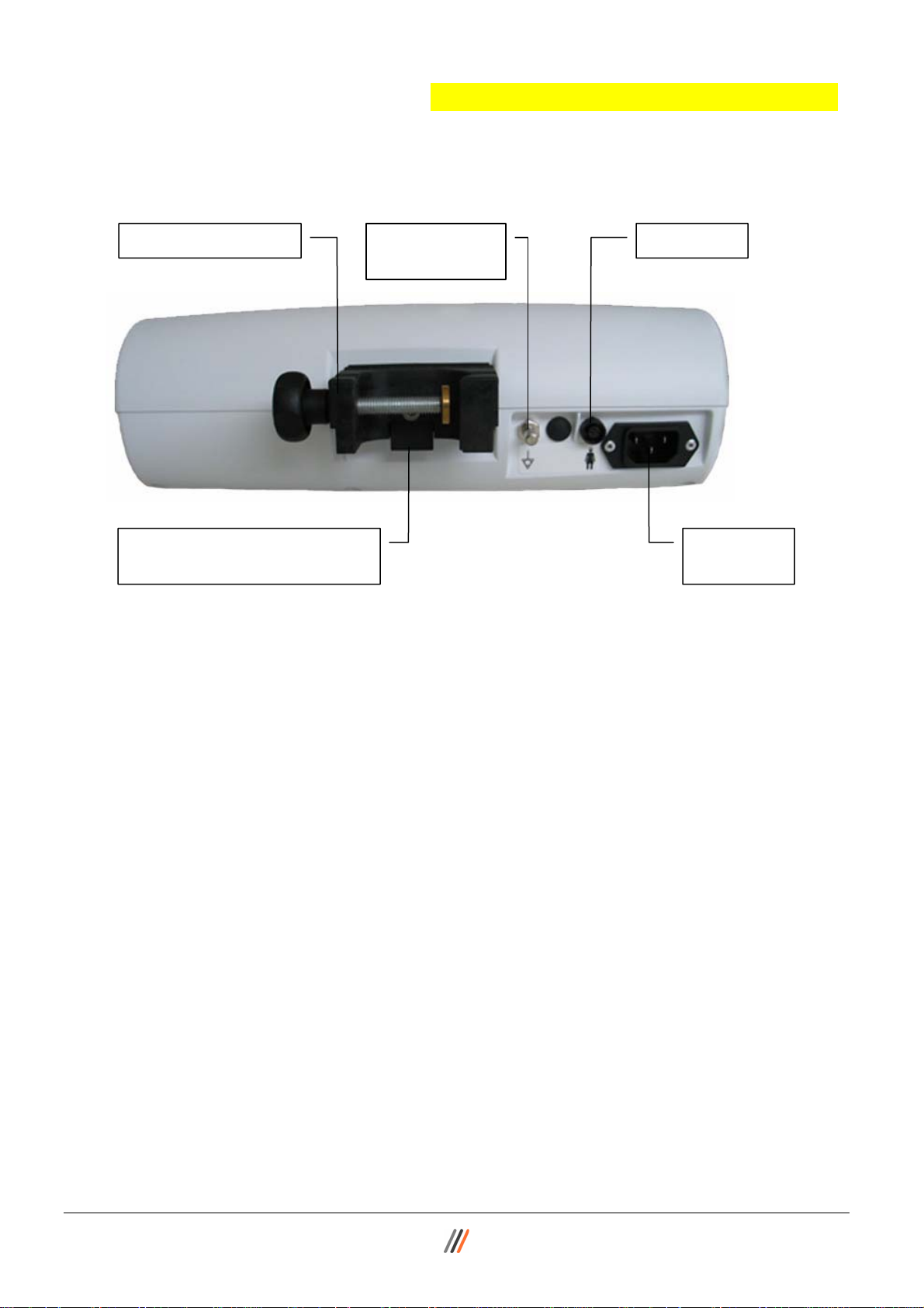
INTRODUCTION
DC-connection & QUICK®100
Docking Station interface
Equipotential
plug
Staff alert Combination clamp
AC power
connection
14.194.A_A600 en.SM.V4.3X ARGUS Medical AG 28.03.06 / PJ 4 / 47
Page 5

1. INTRODUCTION
1.1. General
IMPORTANT!
This service manual is intended for the exclusive use of authorized persons who have
been trained by ARGUS Medical AG in the maintenance and repair of the ARGUS 600
Syringe pump.
The service manual is meant to be used together with the user manual.
IMPORTANT!
ARGUS Medical AG shall not assume any responsibility for any manipulations which
have been carried out on the ARGUS 600 Syringe pump by a non-authorized person.
CAUTION!
The ARGUS 600 Syringe pump may only be used with spare parts, accessories, consumables and syringes with Luer-Lock connections recommended by ARGUS Medical
AG. The functional safety of the pump is not guaranteed if non approved materials are
used. The safety of the patient may be endangered.
This manual contains the latest data available. It is subject to further modifications in
accordance with technical improvements.
INTRODUCTION
2. PUMP CONFIGURATIONS
2.1. General
CAUTION!
The configuration possibilities with the “ARGUS service” PC utility tool and without PC
assistance constitute a modification of the pump and may only be carried out by authorized persons!
CAUTION!
After changing the configuration a function check and a control measurement has to
be performed!
14.194.A_A600 en.SM.V4.3X ARGUS Medical AG 28.03.06 / PJ 5 / 47
Page 6
PUMP CONFIGURATIONS
0
o
P
g
1
5
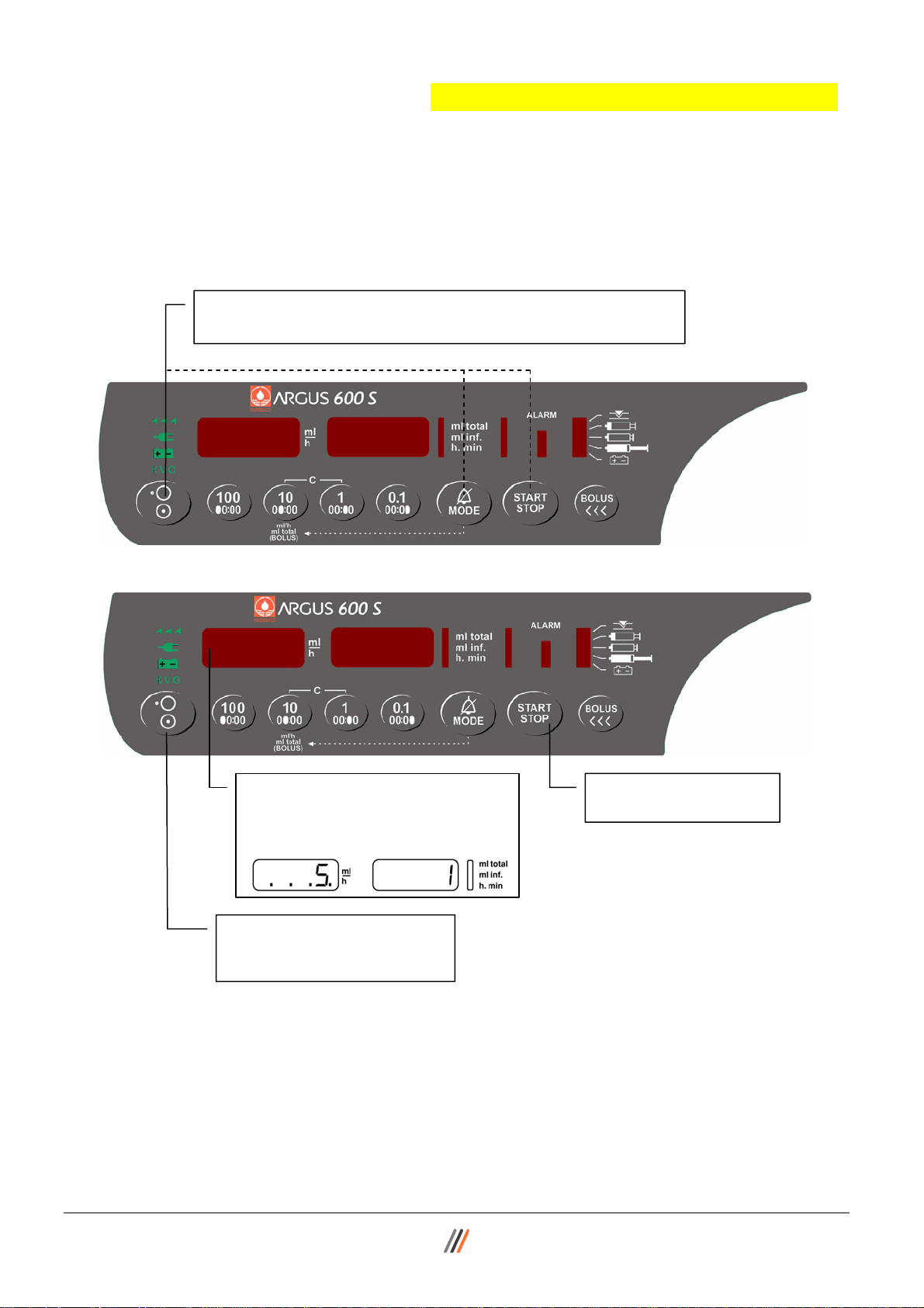
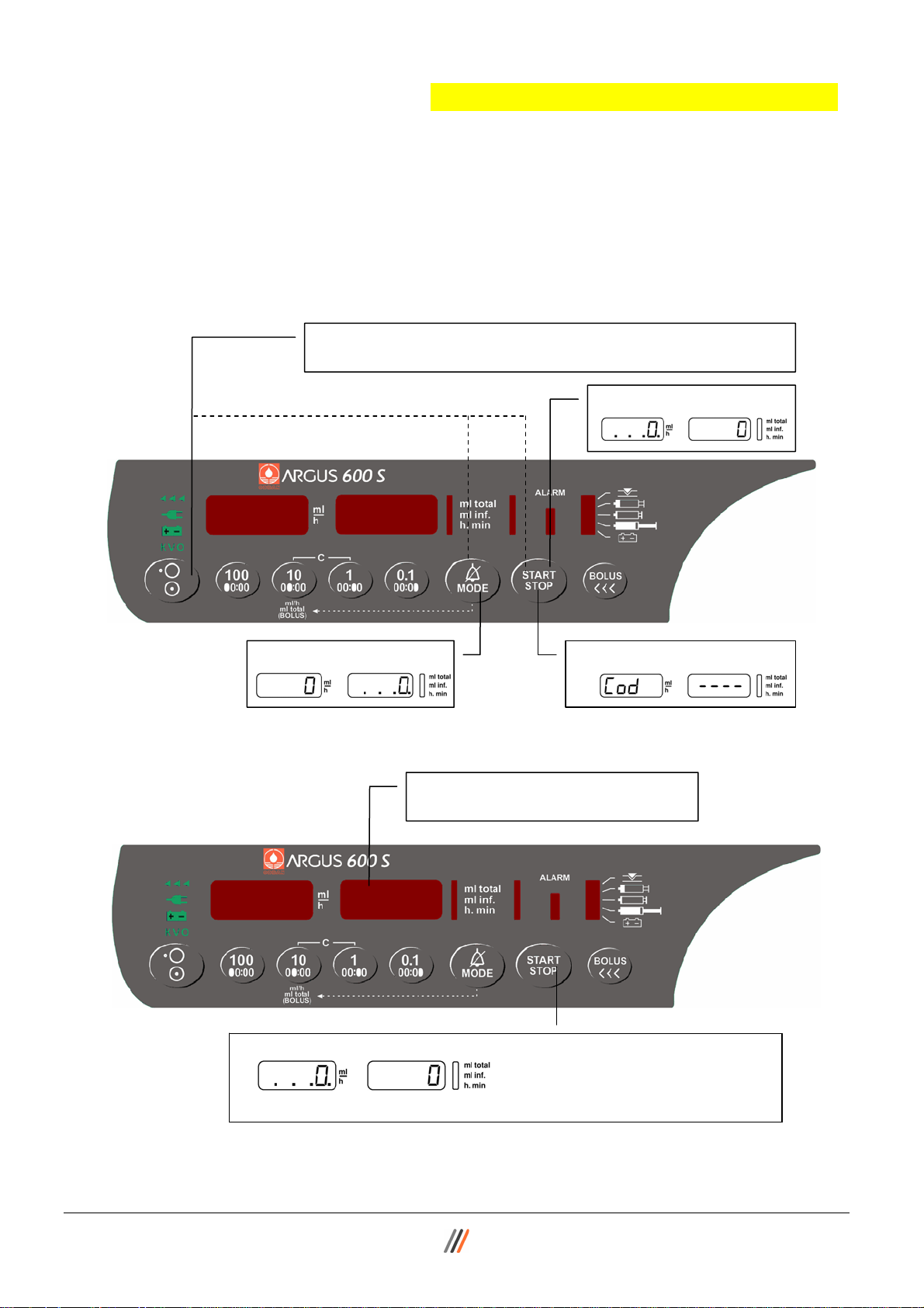
2.2. Interrogation mode (without ARGUS service)
With the interrogation mode you can read the present keypad configuration of the
pump without the possibility to modify any configurations. For a complete overview,
please take the “ARGUS service” PC-tool!
1. To enter into the keypad interrogation mode, switch the pump on
while keeping the keys “MODE” and “START/STOP” pressed.
60
R
... .
Flashing decimal points indicate which display is ready to accept an input by the keys
100, 10 & 1.
In the keypad interrogation mode the left hand display shows the address and the right
hand display shows the according value configured at this address. Please refer to
chapter 2.6. where the meanings of the addresses are explained.
To modify any configuration data you have to go into the configuration mode.
14.194.A_A600 en.SM.V4.3X ARGUS Medical AG 28.03.06 / PJ 6 / 47
3. Enter the requested address (see
chapter 2.6.), e.g. 5. The pro-
grammed value of the address 5
appears in the right hand display.
4. To quit the interrogation
mode press the “ON/OFF”
key at least 2 seconds.
2. Press the
“START/STOP” key.
Page 7
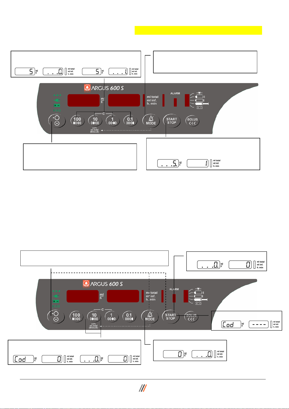
2.3. Configuration mode (without ARGUS service)
-
0
p
o
g
The configuration mode permit you to modify the pump keypad configuration manually
using the keypad. Please refer to chapter 2.6. where the meaning of the addresses are
explained. To have access to all configuration options, please use the “ARGUS
service” PC-tool!
2.3.1. Step 1
1. To enter into the keypad configuration mode, switch the pump
on while keeping the keys “MODE” and “START/STOP” pressed.
PUMP CONFIGURATIONS
2. Press key “START”
60
2.3.2. Step 2
You have now access to all addresses in the list of chapter 2.6.
Select therefore any address in the left display (see next page).
14.194.A_A600 en.SM.V4.3X ARGUS Medical AG 28.03.06 / PJ 7 / 47
3. Press key “MODE” 4. Press key “START” again.
Cod
6. Press key “START” to acknowledge the entered PIN code.
If the PIN was not accepted, the display will change back to 2.3.2. Point 5.
r
5. Enter the PIN Code. If no PIN code
was configured, no entry is required
---
Page 8
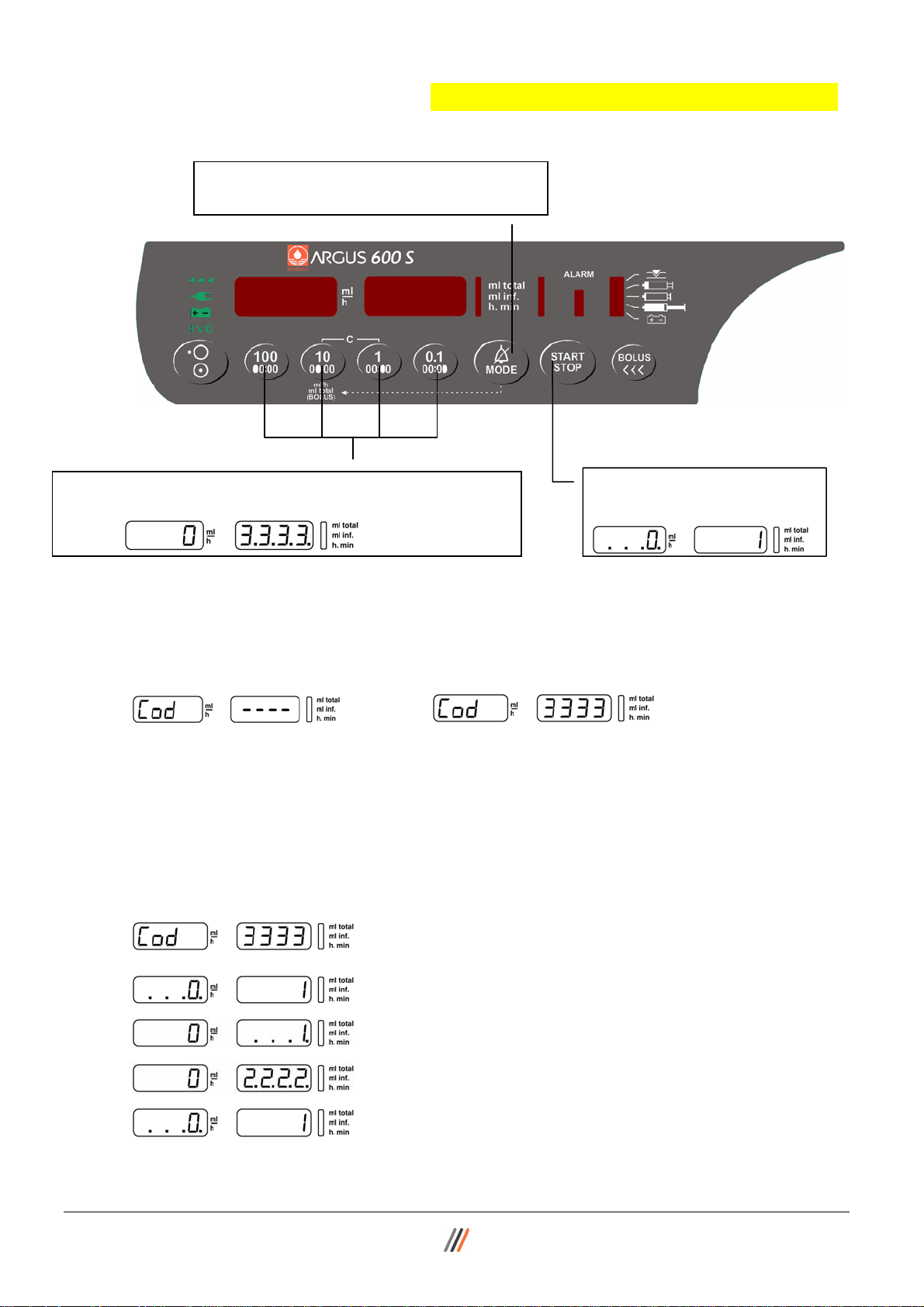
2.3.3. Step 3
5
0
o
P
g.0
8. Enter now the value on the right hand display. The
range of the value is given by the table in chapter 2.6.
10. To quit the configuration mode press the
“ON/OFF” key at least 2 seconds. Changes
in configuration become active, after the
pump is switched on normally again.
Important remark:
Invalid values entered will be corrected automatically by the pump to the maxima or
minima value allowed for the according address!
...
PUMP CONFIGURATIONS
7. After entering an address e.g. 5 press the
key “MODE”. The flashing decimal points
will change to the right hand display.
9. Press key “START/STOP” to acknowledge
the entered value. The flashing decimal points
change back to the left hand display.
2.4. First activation of a PIN Code (write protection)
The activation of a PIN code allows you to protect the configuration from unauthorized
access. To activate the PIN code, enter into the configuration mode.
1. To enter into the configuration mode, switch the pump on
5. Press “MODE” key (Code “0” will be set) then “START”
key to acknowledge the entered PIN code “0”.
14.194.A_A600 en.SM.V4.3X ARGUS Medical AG 28.03.06 / PJ 8 / 47
while keeping the keys “MODE” and “START/STOP” pressed.
60
R
3. Press key “MODE”
2. Press key “START”
4. Press key “START” again
Page 9
0
0
7. Enter now the new PIN Code (max. 4 digit number).
Please remember this code, it will never be visible again!
e.g.
CAUTION!
After you switch the pump OFF and ON again you can enter into the configuration
mode only, if you enter the correct PIN code.
e.g.
Please note: The interrogation mode can always be accessed without the PIN.
6. Press the “MODE” key. The flashing decimal
points will change to the right hand display.
.
.
..
PUMP CONFIGURATIONS
8. Press key “START/STOP” to
acknowledge the new PIN.
2.5. Changing an existing PIN code
Enter the configuration mode using present PIN, select add. “0” and set new code.
Enter actual PIN code and confirm with “START” key.
Press “MODE” key (#0). The flashing decimal points will
change to the right hand display.
Enter the new PIN code and press the “START/STOP”
key to acknowledge the entered code.
14.194.A_A600 en.SM.V4.3X ARGUS Medical AG 28.03.06 / PJ 9 / 47
Page 10
PUMP CONFIGURATIONS
2.6. Address list of the pump configuration (without ARGUS service)
The following list declares the possible configuration options which can be
performed on the pump keypad without using the PC.
All these options can also be configured by the PC-Software “ARGUS service”.
Address Default Function Unit Range
left display
1 2 No Key ON/OFF only at stop valid - 0=No / 1=Yes
2 11 Yes Recall of the last used ml/h rate 3 19 Yes Buzzer at start 4 44 Yes Automatic pressure release 5 49 No Alarm acknowledge with key MODE -
100 361 5 Key ON/OFF delay time • 0.1 s 0 - 31
101 362 2 Display brightness level 1 - 3
102 363 10 Buzzer volume level 5 - 10
103 365 9 Default pressure limit • 100 mbar 2 - 12
200 368 495 Battery capacity (discharge time) min 45 - 615
399 - 600 Enter the calibration menu - 123
Index
PC
0=No / 1=Yes
0=No / 1=Yes
0=No / 1=Yes
0=No / 1=Yes
Note!
The address does not correspond with the index used by the “ARGUS service” tool.
right display
14.194.A_A600 en.SM.V4.3X ARGUS Medical AG 28.03.06 / PJ 10 / 47
Page 11

PUMP CONFIGURATIONS
2.7. Index list of the pump configuration (with ARGUS service)
Index PC Add. Default Function Unit Range
1 No Run indication by running decimal point - No / Yes
2 1 No Key ON/OFF only at stop valid - No / Yes
3 No Rate change allowed only at STOP - No / Yes
4 No Key STOP delayed # 361 - No / Yes
5 No Second entry of rate # 3=Yes, # 9=No - No / Yes
6 No Static alarm (staff alerting system) - No / Yes
7 No Display elapsed time in run mode # 8=No - No / Yes
8 No Display remaining time # 7=Yes - No / Yes
9 No Rate change confirmation in stop mode - No / Yes
10
11 2 Yes Recall of ml/h rate at next power on # 9=No - No / Yes
12 No Recall of ml total at next power on - No / Yes
13 No Recall of ml inf. at next power on - No / Yes
14 No SBS (step by step function) - No / Yes
15 No Display VTBI (volume to be infused) - No / Yes
16 No Syringe type acknowledge at start - No / Yes
17 Yes KVO (KOR) enabled # 60 - No / Yes
18
19 3 No Buzzer at start - No / Yes
20 No Menu Clr (clear ml inf.) # 15=No, # 65 - No / Yes
21
22
23 Yes Menu PrL (pressure alarm limit) - No / Yes
24 Yes Menu CAP (battery capacity) - No / Yes
25
26 No Menu InF (ml inf. since last power on) - No / Yes
27 No Menu dLo (data lock) - No / Yes
28 No Menu Stb (stand by) - No / Yes
29 Yes Menu Med (medication name) - No / Yes
30 No Menu tM (timer alarm) - No / Yes
31
32 Yes Menu boL "bolu Man" / "bolu Auto" (bolus always possible) - No / Yes
33 Yes Menu boLr (bolus rate) # 32=Yes - No / Yes
34 Yes Menu tot (bolus total) # 32=Yes - No / Yes
35 No Display BOLUS-VTBI - No / Yes
36
37
38 Yes Automatic bolus application # 32, 34=Yes - No / Yes
39 No Bolus total to be reset after each auto bolus - No / Yes
40
41 No Clear ml/h after infusion completed - No / Yes
42 No Clear ml total after infusion completed # 41=Yes - No / Yes
43 Yes Syringe clamp diameter outside control - No / Yes
44 4 Yes Automatic pressure release after occlusion - No / Yes
45 Yes Pressure display ON (LED bar graph - 20/40/60/80/100%) - No / Yes
46 No Pressure display with indicator # 45=Yes - No / Yes
47 No Stand by- and battery pre alarm low volume - No / Yes
48 Yes Flashing numeric display at alarm - No / Yes
49 5 No Alarm acknowledge only with key MODE - No / Yes
14.194.A_A600 en.SM.V4.3X ARGUS Medical AG 28.03.06 / PJ 11 / 47
Page 12

PUMP CONFIGURATIONS
55 Yes Med. disp. alternate with rate and ml inf. # 29=Yes - No / Yes
60 No KVO only after infusion completed - No / Yes
65 No Clear and continue # 15=No - No / Yes
75 No Select binder connector for serial interface - No / Yes
100 No
User syringe 10 ml
101 No BD Plastipak
102 No Braun Omnifix
103 Yes Codan
104 No Fresenius Injectomat
105 No Sherwood Monoject
106 No ONCE
107 No PIC Indolor
108 No Rymco
109 No Terumo
110 No Braun Injekt (#43=No)
111 No Chirana-Prema
120 No
User syringe 20 ml
121 No BD Plastipak
122 No Braun Omnifix
123 Yes Codan
124 No Sherwood Monoject
125 No ONCE
126 No Braun Perfusor
127 No Braun Inject
128 No Chirana-Prema
129 No Terumo
130 No Penta Ferte
140 No
User syringe 30 ml
141 No BD Plastipak
142 No Codan
143 No ONCE
144 No Braun Omnifix
145 No Terumo
146 No Penta Ferte
150 No
User syringe 50 ml
151 No BD Perfusion
152 No BD Plastipak
153 No Braun Omnifix
154 No Braun Perfusor
155 No Chirana-Prema
156 No Codan
157 Yes Codan Perfusion
158 No Dispomed
159 No Dipomed Perfusion
160 No Fresenius Injectomat
USEr -10-
b-d PL10
brn OF10
Cod -10FrES In10
Mono -10OnCE -10PIC -10ryco -10tEru -10brn In10
Chir -10-
USEr -20-
b-d PL20
brn OF20
Cod -20Mono -20OnCE -20-
brn PE20
brn In20
Chir -20tEru -20-
PF -20-
USEr -30-
b-d PL30
Cod -30OnCE -30-
brn OF30
tEru -30PF -30-
USEr -50 b-d PE50
b-d PL50
brn OF50
brn PE50
Chir -50-
Cod -50-
Cod PE50
dISP -50-
dISP PE50
FrES In50
10 ml
10 ml
10 ml
10 ml
10 ml
10 ml
10 ml
10 ml
10 ml
10 ml
10 ml
10 ml
20 ml
20 ml
20 ml
20 ml
20 ml
20 ml
20 ml
20 ml
20 ml
20 ml
20 ml
30 ml
30 ml
30 ml
30 ml
30 ml
30 ml
30 ml
50 ml
50 ml
50/60 ml
50/60 ml
50 ml
50/60 ml
50 ml
50 ml
50/60 ml
50 ml
50/60 ml
14.194.A_A600 en.SM.V4.3X ARGUS Medical AG 28.03.06 / PJ 12 / 47
Page 13

PUMP CONFIGURATIONS
161 No Fresenius Perfusion
162 No Ivac
163 No JMS
164 No Sherwood Monoject
165 No PIC Indolor
166 No PIC Indolor Perfusion
167 No Rymco
168 No Terumo
169 No Disoprivan (ZENECA)
170 No ONCE
171 No Braun Proinjekt
172 No Penta Ferte
FrES PE50
IVAC -50-
JMS -50Mono -50PIC -50-
PIC PE50
ryco -50tEru -50dIPr -50OnCE -50-
brn Pr50
PF -50-
50/60 ml
50/60 ml
50/60 ml
50/60 ml
50 ml
50 ml
50 ml
50/60 ml
50 ml
50 ml
50 ml
50 ml
310 300.0 Max. rate ml/h 1 - 300
311 300.0 Prime rate ml/h 1 - 300
312 300.0 Max. bolus rate ml/h 1 - 300
313 1.0 Max. total ml 1 - 10
314
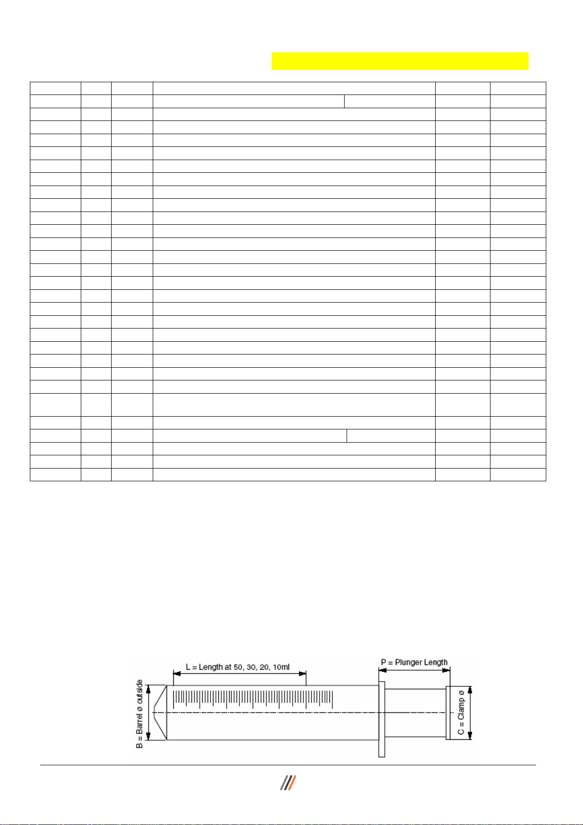
315 61.0 Syringh length mm 45 - 70
316 16.0 Plunger length mm 12 - 30
317 16.2 Barrel diameter mm 15 - 19
user syringe
318 18.7 Clamp diameter
10 ml syringe
parameters
mm 15 - 25
319
320 500.0 Max. rate ml/h 1 - 500
321 500.0 Prime rate ml/h 1 - 500
322 500.0 Max. bolus rate ml/h 1 - 500
323 2.0 Max. total ml 1 - 20
324
325 69.5 Syringh length mm 50 - 80
326 16.8 Plunger length mm 12 - 30
327 21.4 Barrel diameter mm 20 - 24
user syringe
328 23.8 Clamp diameter
20 ml syringe
parameters
mm 20 - 30
329
330 500.0 Max. rate ml/h 1 - 500
331 500.0 Prime rate ml/h 1 - 500
332 500.0 Max. bolus rate ml/h 1 - 500
333 3.0 Max. total ml 1 - 25
334
335 82.0 Syringh length mm 70 - 90
336 16.0 Plunger length mm 12 - 30
337 24.0 Barrel diameter mm 22 - 26
user syringe
338 26.0 Clamp diameter
30 ml syringe
parameters
mm 20 - 30
339
340 999.9 Max. rate ml/h 1 - 999.9
341 999.9 Prime rate ml/h 1 - 999.9
342 800.0 Max. bolus rate ml/h 1 - 800.0
343 5.0 Max. total ml 1 - 25
344
345 90.0 Syringh length mm 70 - 100
346 16.5 Plunger length mm 12 - 50
347 29.4 Barrel diameter mm 28 - 34
user syringe
348 31.0 Clamp diameter
50 ml syringe
parameters
mm 25 - 37
14.194.A_A600 en.SM.V4.3X ARGUS Medical AG 28.03.06 / PJ 13 / 47
Page 14
PUMP CONFIGURATIONS
361 100 5 Key ON/OFF delay time # 4 • 1/10 s 0 - 31
362 101 2 Display brightness level 1 - 3
363 102 7 Buzzer alarm volume level 5 - 10
364
365 103 9 Default pressure limit (PrL levels) • 100mbar 2 - 12
366 1 Pressure display unit (mbar / mmHg / kPa / cmH2O / Psi) Enum 1 - 5
367 3 Time for near empty alarm min 1 - 15
368 200 495 Battery capacity (discharge time) min 45 - 615
369 5 Automatic menu fall back delay time sec 5 - 30
390 0 Last service date in year year 0 - 99
391 0 Last service date in month month 0 - 12
392 0 Last service date in day day 0 - 31
393 0 Service interval in months month 0 - 24
394 0 Service interval in hours of operation hour 0 -10000
395
396 0 Pump serial number xxx 6 yyy xxx 6 yyy
397
398
- 399 600 Enter the calibration menu / clears protection key - 123
518
522 No Allow change of ml total while infusing # 65=No - No / Yes
523
524 Display a department info text (after power up) char
Permissions for serial communication
2
0 = none, 1 = query only, 2 = parametrising, 3 = remote control
Enum 0 - 3
1-16 ASCII
Using the “ARGUS service” tool, the complete and detailed pump configuration can be done.
2.8. User syringe
The ARGUS 600 Syringe pump uses syringes from various manufacturers (see user
manual list of recommended syringes). If you want to use any other brand you must be
sure that the syringe is CE marked and is specified by the syringe manufacturer to be
pressure resistant and/or safe to be used with infusion pumps, the syringe must be
made out of 3 parts (barrel, plunger, sealing) and have Luer-Lock connection (same
applies to extension lines). When all these points are met you are allowed to configure
your own "USER" syringe (one per size). Use the “ARGUS service” tool to enter the
syringe parameters into index 340 – 348 (50 ml syringe).
14.194.A_A600 en.SM.V4.3X ARGUS Medical AG 28.03.06 / PJ 14 / 47
Page 15

PUMP CONFIGURATIONS
2.9. Medication list
2.9.1. General
To display medication names, index 29 (menu "MEd") must be set to "Yes". The selected medication name can be displayed also in alternate mode (rate, ml inf./ med.
name) during infusion, for that set index 56 to “Yes”.
After enabled special function “Med” the following medication names can be selected
via pump keypad (see user manual).
2.9.2. User medication
32 user medication names can be custom defined. Choose between capital and small
letters for a better displayed medication name. Because of the 7-segment pump display some characters maybe difficult to read.
Index
PC
561 UserM 1 User medication name 1 char 1 - 8 ASCII
562 UserM 2 User medication name 2 char
563 UserM 3 User medication name 3
564 UserM 4 User medication name 4
565 UserM 5 User medication name 5
566 UserM 6 User medication name 6
567 UserM 7 User medication name 7
568 UserM 8 User medication name 8
569 UserM 9 User medication name 9
570 UserM 10 User medication name 10
571 UserM 11 User medication name 11
572 UserM 12 User medication name 12
573 UserM 13 User medication name 13
574 UserM 14 User medication name 14
575 UserM 15 User medication name 15
576 UserM 16 User medication name 16
577 UserM 17 User medication name 17
578 UserM 18 User medication name 18
579 UserM 19 User medication name 19
580 UserM 20 User medication name 20
581 UserM 21 User medication name 21
582 UserM 22 User medication name 22
583 UserM 23 User medication name 23
584 UserM 24 User medication name 24
585 UserM 25 User medication name 25
586 UserM 26 User medication name 26
587 UserM 27 User medication name 27
588 UserM 28 User medication name 28
589 UserM 29 User medication name 29
590 UserM 30 User medication name 30
591 UserM 31 User medication name 31
592 UserM 32 User medication name 32
Default Function Unit Range
1 - 8 ASCII
char
1 - 8 ASCII
1 - 8 ASCII
char
char
1 - 8 ASCII
1 - 8 ASCII
char
1 - 8 ASCII
char
1 - 8 ASCII
char
char
1 - 8 ASCII
1 - 8 ASCII
char
char
1 - 8 ASCII
1 - 8 ASCII
char
1 - 8 ASCII
char
char
1 - 8 ASCII
1 - 8 ASCII
char
1 - 8 ASCII
char
1 - 8 ASCII
char
1 - 8 ASCII
char
1 - 8 ASCII
char
1 - 8 ASCII
char
1 - 8 ASCII
char
1 - 8 ASCII
char
1 - 8 ASCII
char
1 - 8 ASCII
char
1 - 8 ASCII
char
1 - 8 ASCII
char
1 - 8 ASCII
char
1 - 8 ASCII
char
1 - 8 ASCII
char
1 - 8 ASCII
char
1 - 8 ASCII
char
1 - 8 ASCII
char
14.194.A_A600 en.SM.V4.3X ARGUS Medical AG 28.03.06 / PJ 15 / 47
Page 16

PUMP CONFIGURATIONS
2.9.3. Defined medication
Index PC Def. Function Range Index PC Def. Function Range
600 Yes (Medication) No / Yes 655 No Procainamide No / Yes
601 No Actilyse No / Yes 656 No Propafenon No / Yes
602 No Adrenaline 0.1 No / Yes 657 No Propofol No / Yes
603 No Adrenaline 0.2 No / Yes 658 No Rapilysin No / Yes
604 No Ajmalin No / Yes 659 No Remifentanyl No / Yes
605 No
606 No Alupent No / Yes 661 No Ropivacaïne No / Yes
607 No Ambroxol No / Yes 662 No Salbutamol No / Yes
608 No Amiodaron No / Yes 663 No Somatostatin No / Yes
609 No Amphotericine No / Yes 664 No Streptokinase No / Yes
610 No Aprotinin No / Yes 665 No Sufentanil No / Yes
611 No Atracurium No / Yes 666 No Terbutaline No / Yes
612 No Bretylium No / Yes 667 No Theopyllin No / Yes
613 No Bupivacïne No / Yes 668 No Thiopental No / Yes
614 No Ceruletid No / Yes 669 No Tirofiban No / Yes
615 No Clonidin No / Yes 670 No Trinitrine No / Yes
616 No Diltiazem No / Yes 671 No Urapidil No / Yes
617 No Dobutamin No / Yes 672 No Urokinase No / Yes
618 No Dopamine No / Yes 673 No Vasopressine No / Yes
619 No Dopexamine No / Yes 674 No Vecuronium No / Yes
620 No
621 No Fentanyl No / Yes 676 No User defined med. 1 No / Yes
622 No Flecainide No / Yes 677 No User defined med. 2 No / Yes
623 No Fluimucil No / Yes 678 No User defined med. 3 No / Yes
624 No Flumazenil No / Yes 679 No User defined med. 4 No / Yes
625 No Furosemid No / Yes 680 No User defined med. 5 No / Yes
626 No Glucose 5% No / Yes 681 No User defined med. 6 No / Yes
627 No Glucose 30% No / Yes 682 No User defined med. 7 No / Yes
628 No Heparin No / Yes 683 No User defined med. 8 No / Yes
629 No Hydrocortison No / Yes 684 No User defined med. 9 No / Yes
630 No Insulin No / Yes 685 No User defined med. 10 No / Yes
631 No Isoprenaline No / Yes 686 No User defined med. 11 No / Yes
632 No KCl No / Yes 687 No User defined med. 12 No / Yes
633 No Ketamin No / Yes 688 No User defined med. 13 No / Yes
634 No Labetalol No / Yes 689 No User defined med. 14 No / Yes
635 No Lidocain No / Yes 690 No User defined med. 15 No / Yes
636 No Liothyronin No / Yes 691 No User defined med. 16 No / Yes
637 No Magnesium No / Yes 692 No User defined med. 17 No / Yes
638 No Midazolam No / Yes 693 No User defined med. 18 No / Yes
639 No Milrinone No / Yes 694 No User defined med. 19 No / Yes
640 No Morphin No / Yes 695 No User defined med. 20 No / Yes
641 No Nacl 0.9 % No / Yes 696 No User defined med. 21 No / Yes
642 No Nalbuphin No / Yes 697 No User defined med. 22 No / Yes
643 No Naloxone No / Yes 698 No User defined med. 23 No / Yes
644 No Neostigmine No / Yes 699 No User defined med. 24 No / Yes
645 No Nicardipine No / Yes 700 No User defined med. 25 No / Yes
646 No Nifedipin No / Yes 701 No User defined med. 26 No / Yes
647 No Nimodipin No / Yes 702 No User defined med. 27 No / Yes
648 No Nitroprussiate No / Yes 703 No User defined med. 28 No / Yes
649 No Noradrenalin No / Yes 704 No User defined med. 29 No / Yes
650 No Omeprazole No / Yes 705 No User defined med. 30 No / Yes
651 No Pancuronium No / Yes 706 No User defined med. 31 No / Yes
652 No Pentoxityllin No / Yes 707 No User defined med. 32 No / Yes
653 No Phentolamine No / Yes
654 No Phenylephrin No / Yes
Alfentanil
Esmolol
No / Yes
No / Yes
660
675
No
No
Risordan
Verapamil
No / Yes
No / Yes
REMARK :
Via barcode reader all medication names can be selected, even if they are not released in the
configuration.
14.194.A_A600 en.SM.V4.3X ARGUS Medical AG 28.03.06 / PJ 16 / 47
Page 17

3. SERIAL COMMUNICATION OF THE PUMP
3.1. General
The ARGUS 600 Syringe pump has two serial interfaces on board. One is wired to the
docking interface connector and one is an optional RS232 connector.
Important remark!
Only the optional RS232 connector is galvanic separated. The docking interface on the
pump is a non galvanic isolated interface! Do not use the docking interface on the
pump together with the interface cable (part 10.093) on a patient!
If the pump is docked into a docking station ARGUS 60 M or ARGUS 100 M, the software switches automatically to the docking interface and the docking station builds the
separation device (galvanic isolation) then.
3.2. Serial communication protocol
The following characteristics are basics for all the ARGUS devices (volumetric pumps,
syringe pumps, docking stations with V4.xx and PCs) which are intended to communicate with the device mentioned in this service manual.
• Full-duplex RS232, currently 4800Baud for single pumps,
9600 Baud for docking stations (also on master/slave-link).
• Simple master (host/PC) – slave (device) communication (host does polling).
• The host has to repeat the request if there is no valid response.
• Uses a checksum (CRC-8).
• Binary data transmission, thus no ASCII/text parsing.
• Fast & direct communication with pumps on ARGUS docking station.
• Specified timeouts during remote mode.
• Basic framing technique used as in the Serial Infrared Link Access Protocol (IrLAP)
Version 1.1.
Please contact your local distributor or ARGUS Medical AG for the complete serial
communication protocol description.
Serial communication of the pump
14.194.A_A600 en.SM.V4.3X ARGUS Medical AG 28.03.06 / PJ 17 / 47
Page 18

ARGUS service
4. ARGUS SERVICE
4.1. General
The ARGUS service utility is a high and user friendly PC software which can configure
and upgrade pumps over PC serial COM port. With this Windows based software you
can also set pump clock, change PIN code, read and print out history and easily replicate pump configurations, and so on. The modern and clearly structured design of this
self-describing PC-tool allows a very easy and rapid modification of the A600 Syringe
pump, the A707 & 708 Volumetric pump and the ARGUS docking station. This software may be available from your local distributor or directly from ARGUS Medical.
REMARK:
“ARGUS service” may only be used with software versions greater or equal to 4.00.
CAUTION!
The syringe pump has to be disconnected from the patient before and while the serial
interface cable is connected to the pump.
The connection of an A600 over serial interface RS232 can be done by connecting the
interface cable (REF 10.093) to the serial interface outlet of the serial PC-COM port.
Start the ARGUS service
Press the button which confirm to your
previously connected device
(ARGUS pump or docking station).
Hold the “10” key while switching-ON the
pump.
Select “Start Configuration” (see next chap-
ter) or “Start Update-Center” (see chapter
5.3.2.).
14.194.A_A600 en.SM.V4.3X ARGUS Medical AG 28.03.06 / PJ 18 / 47
Page 19

4.2. ARGUS service – Configuration
Important remark:
After configuration change, a function check
and control measurement has to be done!
ARGUS service
Select the next step by pressing one of the
buttons (configuration, calibration or toolbox).
The configuration is split into 4 areas:
4.2.1. Configuration tree structure
Configuration (part 1)
All configuration possibilities (indexes) mentioned in chapter 2.7 can be modified
herein in its own tree structure as shown below.
All indexes which are different from the pump firmware default are high lighted.
Calibration (part 2)
Details of the pump calibration can be read out of the pump.
The calibration cannot be modified herein.
Statistic (part 3)
Details about last used infusion parameters, total of infused volume and infusion time
and so on are shown.
Also the last technical failure numbers are listed in this part.
ARGUS (part 4)
This part contains ex-works settings (e.g. pump serial number)
# 20, 23, 24, 26-30, 32-34, 369
# 1, 7, 8, 15, 35, 45, 46, 48, 55, 366, 524
# 2-5, 9, 14, 16, 49, 361, 365, 522
# 11-13, 17, 38-42, 60, 65, 367
# 6, 19, 43, 44, 47, 362, 363, 368, 390-394
# 75, 518
# 561-592, 600-707
# 100-111, 120-130, 140-146, 150-172
# 310-313, 320-323, 330-333, 340-343
14.194.A_A600 en.SM.V4.3X ARGUS Medical AG 28.03.06 / PJ 19 / 47
# 315-318, 325-328, 335-338, 345-348
Page 20

ARGUS service
4.2.2. How to edit a configuration
The following procedure describes how to edit a pump configuration:
1. Press the green “Edit” button.
2. The software will ask for the pump PIN code as next. The button “Edit” changes its
colour and will be renamed into “Download”.
3. If you want to import a configuration from a file press the “Import” button, otherwise
skip this point.
4. Select “Configuration” in the structure tree in the left upper frame.
5. Select the category you want to modify by selecting the according structure tree and
the according index.
6. Modify the according index (within the given restrictions shown).
Each value (number) must be acknowledged by the green “Enter” button.
Go through point 5 & 6 for all further indexes you want to modify.
7. Press the “Download” button if you want to save the modified configuration on the
pump. Otherwise you can save the modified configuration into a file by pressing the
“Save” button.
8. Make a functional check on each pump you have configured.
Important remark!
If a config. has been edited (performed point 1 and 2) once do not switch off the pump!
Otherwise the pump will change always into the PC-configuration mode automatically.
4.3. ARGUS service - Toolbox
With the “ARGUS service” PC-tool you can set the pump clock,
change PIN code, read and print out history, etc.
Select the next step by pressing one of the buttons (set clock, change PIN code, view history,
service interval or replicate).
14.194.A_A600 en.SM.V4.3X ARGUS Medical AG 28.03.06 / PJ 20 / 47
Page 21

ARGUS service
4.3.1. ARGUS service - Toolbox - Pump clock
Use this feature to synchronize the
pump internal clock with your PC time.
Please note: The pump internal clock will set to
the central European time zone (Bern, CET,
GMT +1.00h) as ex-works settings, the pump
internal clock will not switch automatically between
summer and winter time. All history logs
(refer to chapter 4.3.5) will base on this time.
4.3.2. ARGUS service - Toolbox - PIN code
Use this feature to set the pump PIN code.
The setting of a PIN code prevents access to the pump
configuration of third persons.
The default PIN code is “0” by ex-works settings.
Please note: The PIN code corresponds with the PIN code
mentioned in chapter 2.3.2. If a PIN code greater than
9999 is entered, the pump configuration can only be ac-
cessed using the ARGUS service PC tool.
4.3.3. ARGUS service - Toolbox - Service interval
Use this feature to set a reminder alarm on the pump for the next
service interval.
A pending reminder alarm will be shown on the pump display after
power up by a flashing “CtrL” text accompanied by an acoustic
sound.
The point in time when an active reminder alarm occurs, is given by the settings of the
configuration (#393 and #394) and the pump internal clock. Any value higher than 0 on
those indexes will release the reminder alarm after the service interval has elapsed.
Please check those settings first, before you set the reminder alarm!
Please note: By the ex-works settings, the reminder alarm is disabled.
14.194.A_A600 en.SM.V4.3X ARGUS Medical AG 28.03.06 / PJ 21 / 47
Page 22

ARGUS service
4.3.4. ARGUS service - Toolbox - Replicate
Use this feature to replicate fast and easily pump configuration from
a saved configuration file or from a pump to another. A configuration
can only be replicated if the saved configuration (and pump type) corresponds with the firmware of the connected pump in the first 2 digits
(for e.g. 4.30 to 4.31 is possible).
Please note:
The pump internal clock and remainder alarm settings must be done individually on
each pump!
4.3.5. ARGUS service - Toolbox - Pump history
Each registered event has his own date & time stamp. An event is
registered on each pump status change. Please refer to the complete
list mentioned in chapter 4.3.6. below.
4.3.6. History messages
Possible messages appearing in the description of each history event:
Battery defective
Battery low prealarm
Battery low, pump stop
Bolus start
Bolus stop
External power off
External power on
Occlusion, pump stop
PrLimit change
Pump has detected failure
Pump off
Pump on
Pump start
Pump stop (KVO)
Rate change
Enter setup mode
Data lock off
Data lock on
Pump off in remote mode
Total (VTBI) change
No information available
Exit setup or PC configuration mode
Syringe barrel switch, pump stop
Syringe barrel diameter, pump stop
Syringe drive unit, pump stop
Syringe clamp, pump stop
Syringe clutch, pump stop
Syringe empty, pump stop
Syringe near empty
Timer alarm, pump stop (KVO)
Total volume reached, pump stop (KVO)
Logon in PC configuration mode
Logoff in PC configuration mode
Infsum cleared
Pump start, ext. changed parameters
Any defaults written in EEPROM area
CRC error in PC configuration mode
Enter PC configuration mode
PC communication timeout reached
Pump start in remote mode
Rate change during remote mode
14.194.A_A600 en.SM.V4.3X ARGUS Medical AG 28.03.06 / PJ 22 / 47
Page 23

ARGUS service
4.3.7. History printout example
All pre-alarms, alarms and technical failures are high lighted in a different colour.
14.194.A_A600 en.SM.V4.3X ARGUS Medical AG 28.03.06 / PJ 23 / 47
Page 24

5. SOFTWARE UPDATES
5.1. General
This chapter describes the procedure to perform a software update on the
ARGUS 600 Syringe pump. To check the installed software release in your
ARGUS 600 S press the "MODE" key while switching on the pump.
Please refer to your local distributor or ARGUS Medical AG to determine the latest software release able to run on your device hardware.
NOTE: Flash upgrades are only possible, starting from software version 3.0X.
5.2. Requirements for a software update
To update an ARGUS Medical device, the following items are needed:
• PC with Microsoft® Windows™ 2000 or newer, .NET Framework must be installed!
• RS-232 serial interface cable (part no. 10.093)
• PC configuration tool “ARGUS service”
• Latest firmware included in a text file named “A600_xxx.txt”.
(“xxx” is the placeholder for the firmware version).
Those items are available from your local distributor or from ARGUS Medical AG.
SOFTWARE UPDATES
5.3. Software update procedure
5.3.1. General
Please carefully check the software present installed on the pump. If you have a firm-
ware < version 4.xx please follow chapter 5.3.2 to upgrade the firmware.
5.3.2. Update of a pump with firmware > V4.xx
Important remark!
The actual calibration (and configuration) will be stored in a file on the PC, please
be sure you will restore the correct file into the pump after the firmware update.
Otherwise invalid calibration values will be stored on the pump.
1. Connect the pump to the serial interface of your PC. Please
remember the COM port number where you have connected
the pump.
2. Switch the pump ON while keeping key [10] pressed.
3. Start the PC configuration tool “ARGUS service” and select
the according COM port.
4. Go into the configuration part and save the present pump configuration (incl. calibration) to a file.
5. Close the “ARGUS service” and switch the pump OFF.
6. Perform point 3 again, go into the “Update center”.
14.194.A_A600 en.SM.V4.3X ARGUS Medical AG 28.03.06 / PJ 24 / 47
Page 25

SOFTWARE UPDATES
7. Select the requested pump firmware file by pressing the button “…”.
8. Press “Update the pump firmware”. Follow the instructions displayed on the PC. The firmware will
be installed and the pump will be switched off
automatically.
9. Go into the configuration part again (refer to point 2-3). Press
the “Edit” button and enter the pump PIN code (default PIN after firmware update is 0).
10. Restore the old configuration (incl. calibration) from the previ-
ous created file.
11. Restore the configuration by pressing the “Download” button.
12. Perform a standard safety check (see chapter Error! Refer-
ence source not found.), normally the calibration will not be
destroyed if the procedure is carefully performed step by step.
5.3.3. Upgrade of a pump with firmware < V4.xx
With the “Update center” it is also possible to upgrade pump firmware older than V4.xx.
Important remarks!
The actual calibration (and configuration) will be stored temporary on the PC,
please perform the upgrade procedure pump by pump. Otherwise invalid calibration values will be stored on the pump.
It is urgent necessary to perform a standard safety check (see chapter 10)!
1. Go into the “Update center” (see point 1-4 of
chapter 5.3.2.):
2. Switch the pump ON by keeping the key [10]
pressed.
3. Backup the legacy configuration (present configuration before the firmware update). This
may take several seconds.
4. Switch the pump OFF.
5. Press “Upgrade to bootloader 4”. Follow the
instructions displayed on the PC. The bootloader will be upgraded then.
6. Select the requested pump firmware file by
pressing the button “…”.
7. Press “Update the pump firmware”. Follow the
instructions displayed on the PC. The firmware will be installed and the pump will be
switched off automatically.
14.194.A_A600 en.SM.V4.3X ARGUS Medical AG 28.03.06 / PJ 25 / 47
Page 26

5.4. Safety aspects
Be aware of the following points:
SOFTWARE UPDATES
8. Switch the pump ON while keeping key [10]
pressed. Start the “ARGUS service” tool and
select the according COM port.
9. Import configuration from backup. The calibra-
tion values and configuration of last connected
pump will be imported.
10. Download it to the pump by pressing the
“Download” button.
11. Important:
Perform a standard safety check (see
chap.10), the calibration values maybe lost
during the upgrade procedure!
! For medical device traceability your local distributor or ARGUS Medical AG needs to
be informed about every device updates (serial number) you performed!
! Do not make any software updates when the device is used and/or connected to a
patient!
CAUTION!
A standard safety check (see chapter 10) has to be performed after every software up-
date!
14.194.A_A600 en.SM.V4.3X ARGUS Medical AG 28.03.06 / PJ 26 / 47
Page 27

6. MAINTENANCE
6.1. General
CAUTION!
Only authorized persons who have been trained by ARGUS Medical AG or by the local
distributor are allowed to service the ARGUS 600 Syringe pump. In case of repair re-
quest, send the unit with the filled out “repair order form” (see chapter 11) to the local
distributor. Further information is available from:
CAUTION!
The Safety Standard Check (SSC) has to be performed at least every 24 month or after
10'000 hrs of operation. The check has to be done in accordance to chapter 10.
No special maintenance of the ARGUS 600 Syringe pump is necessary. There are no
wear and tear parts.
MAINTENANCE
ARGUS Medical AG
CH-3627 Heimberg / Switzerland
E-mail: info@argusmedical.com
6.2. Recalibration
6.2.1. General
The ARGUS 600 Syringe pump has been calibrated by the manufacturer with a calibrated spring gauge. The basic ex works configuration enables only one CODAN sy-
ringe type per size. To select a different pre-configured syringe, see chapter 2.7.
CAUTION!
For a new syringe calibration of a none recommended brand, see chapter 2.6.
14.194.A_A600 en.SM.V4.3X ARGUS Medical AG 28.03.06 / PJ 27 / 47
Page 28

6.3. Final calibration
1 2 3
3 9 9
6.3.1. General
The ARGUS 600 Syringe pump contains different calibration steps:
- syringe barrel holder (pulled and unpulled)
- drive unit (totally left and right)
- clamp (fully closed and opened)
- barrel diameter (17 and 31 mm)
- plunger length (20 and 120 mm)
- clamp diameter (20 and 32 mm)
- pressure limit (0.2 and 1.2 bar)
CAUTION!
A calibration becomes necessary if the pressure control measurements were not
accurate enough, a new syringe configured or any spare part was replaced (e.g.
pressure sensor, main board, etc.)
Needed equipment: - a manometer with a resolution of 0.1 bar
- a 3-way stop cock
- a syringe extension line
- calibration part-2 & part-3
- a recommended 50 ml syringe
MAINTENANCE
6.3.2. Enter into the calibration mode
2. Select address 399 in this display, then press key “MODE”.
14.194.A_A600 en.SM.V4.3X ARGUS Medical AG 28.03.06 / PJ 28 / 47
1. Enter into the configuration mode
(see chapter 2.3).
3. Enter value 123
.
...
in this display.
4. Press the START/STOP” key.
Page 29

d
0
P
0
6.3.3. Syringe barrel holder range verification (barrel diameter)
Please verify that the displayed values in the right hand display are within the
correct ranges (without calibration part)
17b
Valid range for the syringe barrel holder (unpulled): 700 ±300
Valid range for the syringe barrel holder (pulled): 4200 ±300
NOTE!
Please refer to chapter "Rough alignments" if the displayed value is out of range!
70
MAINTENANCE
6.3.4. Drive unit range verification (plunger)
Press “MODE” key and verify that the displayed values in the right hand display
are within the correct ranges (without calibration part)
14.194.A_A600 en.SM.V4.3X ARGUS Medical AG 28.03.06 / PJ 29 / 47
120
Valid range for the drive unit (totally left): 600 ±200
Valid range for the drive unit (totally right): 4400 ±200
NOTE!
Please refer to chapter "Rough alignments" if the displayed value is out of range!
60
Page 30

d
0
6.3.5. Clamp range verification (clamp diameter)
Press “MODE” key and verify that the displayed values in the right hand display
are within the correct ranges (without calibration part)
20c
Valid range for the clamp (fully closed): 600 ±300
Valid range for the clamp unit (fully opened): 2500 ±300
NOTE!
Please refer to chapter "Rough alignments" if the displayed value is out of range!
70
MAINTENANCE
6.3.6. Syringe barrel holder diameter calibration (part-3)
Press “MODE” key until the display indicates “17bd” “xxxx” and put the calibration
part-3 (∅17, l=120mm) in place.
Important remark: Verify the firm capture of the beaks and make sure
there is no gap between drive unit and calibration part.
calibration part-1 calibration part-3
(REF 11.194) (REF 10.153)
14.194.A_A600 en.SM.V4.3X ARGUS Medical AG 28.03.06 / PJ 30 / 47
Page 31

d
0
P
0
d
0
6.3.7. Drive unit (plunger) length calibration (part-3)
17b
Press “START/STOP" key to store the barrel diameter for 17 mm.
NOTE! Each stored value will be acknowledged by a sound.
Press “MODE” key, the display indicates “120P” “xxxx”.
120
Press “START/STOP" key to store the plunger length for 120 mm.
110
408
MAINTENANCE
6.3.8. Clamp diameter calibration (part-3)
Press “MODE” key, the display indicates “20cd” “xxxx”.
14.194.A_A600 en.SM.V4.3X ARGUS Medical AG 28.03.06 / PJ 31 / 47
20c
Press “START/STOP" key to store the clamp diameter for 20 mm and then remove the calibration part-3.
91
Page 32

d
0
P
0
d
0
6.3.9. Syringe barrel holder diameter calibration (part-1)
Press “MODE” key, the display indicates “31bd” “xxxx”, then put the calibration
part-1 (∅31, l=20mm) in place.
31b
Press “START/STOP" key to store the barrel diameter for 31 mm.
346
MAINTENANCE
6.3.10. Drive unit (plunger) length calibration (part-1)
Press “MODE” key, the display indicates “20P” “xxxx”.
Press “START/STOP" key to store the plunger length for 20 mm.
6.3.11. Clamp diameter calibration (part-1)
Press “MODE” key, the display indicates “32cd” “xxxx”.
Press “START/STOP" key to store the clamp diameter for 32 mm and then remove the calibration part-1.
20
32c
76
176
14.194.A_A600 en.SM.V4.3X ARGUS Medical AG 28.03.06 / PJ 32 / 47
Page 33

0
b
0
6.3.12. Pressure limit calibration (minimal)
Insert a filled 50 ml syringe and connect the patient line to the pressure measurement system (manometer). Press "MODE" key, the display indicates "0.2b"
"xxxx" and the pump starts to run with a low rate. Close the line (occl.)
NOTE!
To speed up the process increase the infusion rate in steps, by pressing the key
"1". It is recommended to reduce the rate (with key “100”) when the pressure on
the manometer is close to 0.2 bar, this allows a more precise calibration.
Important remark:
For each pressure calibration step, a new syringe from the same brand and batch
must be used. For a more precise calibration, use a spring gauge. The ex works
calibration has been performed with a spring gauge.
.
2
175
Simulate an occlusion by the 3-way stop cock
and start a pressure build-up.
Wait until 0.2 bar is reached on the scale and
then press the "START/STOP" key immediately, to register the minimal pressure limit
value for 0.2 bar.
The spring gauge can be ordered directly from
ARGUS Medical AG.
MAINTENANCE
14.194.A_A600 en.SM.V4.3X ARGUS Medical AG 28.03.06 / PJ 33 / 47
Page 34

6.3.13. Pressure limit calibration (maximal)
1
b
0
Press "MODE" key, the display indicates "1.2b" "xxxx" and the pump continuous
to run with a low rate.
NOTE!
To speed up the process increase the infusion rate in steps, by pressing the key
"1". It is recommended to reduce the rate (with key “100”) when the pressure on
the manometer is close to 1.2 bar, this allows a more precise calibration.
.
2
275
Wait until 1.2 bar is reached on the scale and
then press the "START/STOP" key
immediately, to register the maximal pressure
limit value for 1.2 bar.
Switch off the pump.
MAINTENANCE
6.4. Pressure control and pump accuracy measurement
Pressure control
Start an infusion at an infusion rate of 200 ml/h according to the user manual and set
the pressure limit at 900 mbar. Connect a manometer with the system to see the pressure in the tube and then simulate a downstream occlusion.
The pump must stop and the alarm must be activated at the default pressure limit of 900
mbar ±200 mbar.
If the result of this control measurement does not fulfil the stated requirement, a pressure calibration according to chapter "Final calibration" has to be done.
Pump accuracy
Select a 50 ml syringe (e.g. Cod -50-) to check the pump accuracy. Insert a new
(e.g. Codan Perf. 50 ml) filled with distilled water and start to pump into a cup placed on
a balance.
Pump settings: set rate at 200 ml/h, set “ml total” at 20 ml
Net weight result: 20 g ±2%
14.194.A_A600 en.SM.V4.3X ARGUS Medical AG 28.03.06 / PJ 34 / 47
syringe
Page 35

6.5. Rough alignments
Drive unit (plunger) length (P):
- Go into the configuration mode (see chapter 2.3)
- Select address 399
- Press key "MODE"
- Enter data 123
- Press key "START/STOP", the display indicates "17bd" "xxxx"
- Press key "MODE" until "120P" "xxxx " is displayed
- Loosen the lock screw of the cogwheel on the plunger potentiometer axle
- Move syringe drive (without syringe) fully to the left
- Turn the potentiometer axle in clockwise direction up to the final position and
afterwards in the counter clockwise direction until approx. 600 is displayed
- Fix the lock screw!
- Control whether the full stroke can be made
Syringe clamp diameter (cd):
- Go into the configuration mode (see chapter 2.3)
- Select address 399
- Press key "MODE"
- Enter data 123
- Press key "START/STOP", the display indicates "17bd" "xxxx"
- Press key "MODE" until "20cd" "xxxx" is displayed
- Remove the syringe and make sure the clamp is fully closed
- Remove the cover of the drive unit (10.151)
- Remove the clamp spring
- Loosen the lock screw of the position lever (11.208)
- Turn carefully the potentiometer axle (R2) in counter clockwise direction up to
the final position
- Turn position lever (11.208) counter clockwise until it touches the housing
(see picture above)
- Fix the lock screw (make sure the position lever touches the housing)
- Re-install the clamp spring, then a value of approx. 600 is displayed
- Re-install the cover of the drive unit
- Control whether the clamp stroke can be made
MAINTENANCE
11.208
14.194.A_A600 en.SM.V4.3X ARGUS Medical AG 28.03.06 / PJ 35 / 47
Page 36

MAINTENANCE
Syringe barrel holder diameter (bd):
- Go into the configuration mode (see chapter 2.3)
- Select address 399
- Press "MODE" key
- Enter data 123
- Press "START/STOP" key, the display indicates "17bd" "xxxx"
- Loosen the lock screw of the potentiometer R14 on the power board
- Turn the potentiometer axle (R14, on the power board) in the counter clockwise
direction up to the final position and afterwards in the clockwise direction until
approx. 700 appears in the display.
- Fix the lock screw
- Control whether the syringe barrel can make the full stroke.
Strain (pressure) gauge (b):
Caution: No syringe is inserted and the syringe drive is positioned fully right.
- Go into the configuration mode (see chapter 2.3)
- Select address 399
- Press "MODE" key
- Enter data 123
- Press key "MODE" several times until "0.2b" "xxxx" is displayed.
- Adjust the screw of the trimmer (R13, on the power board) until approx. 1500 is
displayed.
Power Board
14.194.A_A600 en.SM.V4.3X ARGUS Medical AG 28.03.06 / PJ 36 / 47
Page 37

6.6. Battery capacity calibration
Each battery is subject to a chemical process with a slowly decreasing running time. After many charge and discharge cycles the battery may not have the capacity to provide
the running time shown in the menu "CAP".
To adjust the running time of the used battery please follow these steps:
- Go into the configuration mode (see chapter 2.3).
- Select address "200" in the left display (or index "368" if you are using the
“ARGUS service” tool).
- Enter the data "615" in the right display and press the "START/STOP" key to
accept the data. This will set the battery discharge time to the maximum of
>10 hours.
- Switch the pump off.
- Be sure you have unplugged the line connection.
- Switch the pump on and run the pump on battery until it switches off.
- Charge the battery for more than 16 hours.
- Switch on the pump and start an infusion with a rate of 5 ml/h. The infused sum
at this rate multiplied by 12 is now equal to battery operating time in minutes.
- Leave the pump running on battery until it switches off again.
- Connect pump to the AC line.
- Switch the pump on while keeping the key "1" pressed. Multiply the value in the right
display by 12, this gives the capacity of the battery in minutes. Multiply this time by
0.8 and enter the result on address "200" in the configuration mode (or index “368” if
you are using the “ARGUS service” tool). This time defines from now on, the battery
running time of the pump including a 15 minutes pre-alarm (valid after a full charge).
- Standard battery 6V/1.2 Ah
If this time is less than 2 h, you should replace the battery (part 12.032). If the specified typical time of 2 h is not required, the battery has to be changed only if the time
less than 1.5 h, to respect to environmental pollution.
- High energy battery 6V/4 Ah
If this time is less than 8 h, you should replace the battery (part 12.026). If the specified typical time of 8 h is not required, the battery has to be changed only if the time
less than 5 h, to respect to environmental pollution.
MAINTENANCE
6.7. Pump specifications
Please refer to the user manual for the specifications (chapter 9).
14.194.A_A600 en.SM.V4.3X ARGUS Medical AG 28.03.06 / PJ 37 / 47
Page 38

6.8. Fault codes and "CtrL" message
6.8.1. Fault codes
A technical failure will be indicated by the pump with a continuous alarm. During this
state, the fault code which causes the pump to fail can be displayed by pressing the
“MODE” key. If the pump was switched OFF after a detected failure, the fault code will
be stored in the history and also in the configuration of the pump, please refer to chap-
ter 2.7 (index 380 - 385). Possible fault codes:
Fault
Code
F_20 Internal watchdog
F_21 ROM test
F_22 ROM check (Runtime)
F_23 RAM test/check
F_24 XRAM test/check
F_25 CPU test
F_26 Invalid function menu
F_27 EEPROM data invalid
F_28 RTC (real time clock) data invalid, no RTC etc.
F_29 Stepper motor power test (delayed 5s)
F_30 Plunger position calculation failed
F_31 Check for near empty
F_32 5Volt supply out of range
F_33 20Volt supply out of range (delayed 5s)
F_34 Pressure reference out of range (LM385 2.5V)
F_35 Pressure signal out of range
F_36 Pressure result invalid
F_37 Pressure sensor test failed
F_38 Barrel diameter signal test failed
F_39 Barrel diameter signal out of range
F_40 Clamp diameter signal out of range
F_44 Address invalid for config-EEPROM
F_45 Address invalid for history-EEPROM
F_46 Frequency from µC or RTC (real time clock) out of range
F_47 Display-print not present
F_48 Key(s) too long active
F_54 Movement result invalid
F_55 Frequency calculation
F_56 Invalid volume adjustment over time
F_57 Rotation (SW overflow)
F_58 Internal volume control (10/ml)
We recommend replacing the main board in case a fault code is not included in above list.
Failure
MAINTENANCE
6.8.2. "CtrL" message
If the time of the safety standard check is elapsed, the reminder alarm "CtrL" will be displayed after power up. The "CtrL" message also lights up when an invalid serial number
is set or a faulty calibration done (pressure & mechanic).
14.194.A_A600 en.SM.V4.3X ARGUS Medical AG 28.03.06 / PJ 38 / 47
Page 39

REPLACEMENT OF PARTS
7. REPLACEMENT OF PARTS
7.1. General
CAUTION!
The ARGUS 600 S may only be used with accessories and spare parts which have
been approved by ARGUS Medical AG for safe technical use.
CAUTION!
If a new syringe was configured, pressure sensor, complete syringe drive, side wall,
housing, main board or power board was replaced, a full calibration is required.
Battery replacing:
After a battery change a safety standard check becomes necessary or at least a visual
check of the connections
Disassembly of the housing:
Disconnect the power cord and all interface connections prior to disassembly. Remove
pole clamp at the rear side. Remove the 7 screws on the casing base (6 • M4 and 1 •
M3), the 2 screws on left side cannot be removed completely. Place the casing cover
behind the casing base.
Remove the main board:
Remove the battery connector and all other cables of the main board.
Remove the syringe drive:
Move the drive unit fully right and remove the fixing plate. Unsolder the connecting
leads of the strain gauge (DMS) on the power board. Move the drive unit fully left. Disconnect earth cable from side wall, motor cable from main board and flex cable from
power board. Remove the syringe drive out from the housing by fully pressed clamp &
clutch levers.
Remove the cover drive unit:
Remove the 3 screws on the cover.
Important:
To disassemble the unit, open the beaks by hand one third (or put a coin be-
tween the beaks) then pull the cover with the levers out of the housing.
Remove the power board:
Important: Replacing the power board requires a new rough alignment of syringe barrel
holder diameter, strain gauge and a finale calibration. Unsolder the connecting leads of
the strain gauge on the power board. Remove all cables from the board and the 4 fixing
screws. Remove the board carefully.
Insert the power board:
Syringe barrel holder must be in the closed position (no syringe inserted). Loosen the
lock screw of the cogwheel on the syringe barrel holder potentiometer (R14) axle. Fix
the power board with the 4 screws. Make sure the lock screw of potentiometer R14 is
accessible from above. Solder the connecting leads of the strain gauge and connect the
other cables. Make sure to remove the AC power cord and operate the pump (with open
housing) on battery power for rough alignments.
14.194.A_A600 en.SM.V4.3X ARGUS Medical AG 28.03.06 / PJ 39 / 47
Page 40

REPLACEMENT OF PARTS
Replace the sidewall (motor):
After each disassembly or replacing of the sidewall, the rough alignment of the strain
gauge and a final calibration must be executed to guarantee a perfect pump operation
and pressure monitoring.
For the part numbers of replacements parts consult the following chapter:
14.194.A_A600 en.SM.V4.3X ARGUS Medical AG 28.03.06 / PJ 40 / 47
Page 41

REPLACEMENT OF PARTS
g
7.2. Spare parts
10.059 Cable staff alert 2m
10.061 Display board A600 10.066 Spindle nut complete
10.068 Motor and gear
10.087 Combination clamp
10.091 Pushbutton Kit
10.093 Interface cable,
docking & pumps
10.131 DC-Plu
10.146 Power board A600 Flash
10.147 Mainboard A600 Flash
10.148 Kit Flex cable Flash version
10.149 Casing base Flash version
10.150 Syringe drive complete
14.194.A_A600 en.SM.V4.3X ARGUS Medical AG 28.03.06 / PJ 41 / 47
10.151 Cover drive unit
10.152 Housing drive unit
Flash version
Page 42

REPLACEMENT OF PARTS
10.153 Calibration part 3
10.155 Edge board holder
Flash version
10.157 Driving head complete
11.168 Syringe barrel holder
11.170 Side wall motor incl. DMS
11.188 Syringe guide
11.189 Casing cover
11.194 Calibration part 1
11.199 + 11.201 + 11.225 - 11.232
Short instructions A600
(DE,EN,FR,PT,SW,SP,NL,DK,IT,CZ)
11.200 Identification plate A600
11.267 Battery cover 4Ah11.213 Front panel A600
11.270 Clamp (top) Flash version 11.271 Clamp (bottom) Flash version 11.272 Cog segment (top)
14.194.A_A600 en.SM.V4.3X ARGUS Medical AG 28.03.06 / PJ 42 / 47
Page 43

REPLACEMENT OF PARTS
11.273 Cog segment (bottom)
11.276 Spring clamp Flash version 11.277 Casing (driving head)
11.274 Working lever Flash version 11.275 Beaks lever Flash version
11.278 Torsion spring Flash version
12.026 Battery 6V/4Ah 12.032 Battery 6V/1.2Ah
12.035 Pressure gauge with
stopcock (manometer)
14.194.A_A600 en.SM.V4.3X ARGUS Medical AG 28.03.06 / PJ 43 / 47
Page 44

8. WIRING DIAGRAMM
WIRING DIAGRAMM
14.194.A_A600 en.SM.V4.3X ARGUS Medical AG 28.03.06 / PJ 44 / 47
Page 45

9. BLOC SCHEMATIC
BLOC SCHEMATIC
14.194.A_A600 en.SM.V4.3X ARGUS Medical AG 28.03.06 / PJ 45 / 47
Page 46

10. SAFETY STANDARD CHECK
SAFETY STANDARD CHECK
Safety Standard Check (SSC)
Serial-no.: …………………………....…………..
Software version: ……………………………...… Customer: ……………...……………………..
Hospital: ………………………………..……...… Department: …………………………………..
The SSC has to be performed at least every 24 months or after 10'000 hours of operation.
The check has to be done in accordance to the user- and service manuals.
Check if a software upgrade is required
1
Visual check for damage, cleanness and
completeness. Remove the syringe and ensure
2
that the barrel holder is closed at the end.
Keep "MODE" key pressed while switching on
the pump
3
Press each key in the following order: "100",
"10", "1", "0.1", "MODE", "BOLUS",
4
"START/STOP"
Hold the clamp lever in its upper position
Press the syringe presence switch
Actuate the clutch lever, release it
5
Release the clamp lever
Release the syringe presence switch
Insert a 50 ml syringe and test the pump at its
6
max. rate (999.9 ml/h)
Check the occlusion-alarm pressure. See
chapter "Pressure control and pump accuracy
7
measurement".
Check the pump accuracy. See chapter
8
"Pressure control and pump accuracy …".
Check the external connection “nurse-call” - Relay contact switches
9
Check the Docking Station interface (if the
10
pump is used in a Docking Station)
Check time and date - Get the history entries
11
Charge the battery min. 16 hours on mains - The indicator “external supply” must light
12
Discharge the battery at a rate of 6 ml/h until
the pump switches off automatically. Keep "1"
key pressed while switching on the pump. Read
13
the infused sum (ml inf.) and multiply it with 10.
Charge the battery again
14
Electrical test according to EN 60601-1
15
(all measurements made with a power cable 2.5m)
4
The pump has passed the SSC and is safe for use
3
1
2
5
Inventory-no.: ………………….…..………....
- Housing, labels, accessories, connectors,
power cable, etc.
- Beaks must be fully closed without a
syringe inserted
- Display of pump type and software release
- Display of 2, 4, 7, F., in numeric display
- Display of all operation/alarm indicators
- Every key is aknowledged by a acoustical
click, at the end an alarm (buzzer and
LED) occurs
1
"Syringe" alarm
2
No "Syringe" alarm
3
"Syringe" alarm, no "Syringe" alarm
4
"Syringe" alarm
5
"Syringe" alarm
- Running smooth?
- Pressure increase to ≥ 1.2 bar possible?
- Preset level: ………….. mbar
- Measured level: ………. mbar
- Preset ml total: 20 ml
- Measured volume: ………. ml
(see chapter "Bloc schematic")
- The indicator “external supply” must light
on a docked pump
- The green indicator "battery" must light
while discharging
- Running time = ml inf. • 10 = ………. min
Reference: 120 min or 480 min
- Visual check of mains connector
- Measurements attached
ARGUS 600_en
Date / Name: ……...…………………………….
ARGUS Medical AG
14.194.A_A600 en.SM.V4.3X ARGUS Medical AG 28.03.06 / PJ 46 / 47
Signature: ………………………………....…
Page 47

11. REPAIR ORDER FORM
ARGUS Medical AG / Heimberg Switzerland
REPAIR ORDER FORM
Purchase order / Proforma invoice number:
Customer name and address:
Name of contact person: Tel. number:
REPAIR ORDER FORM
Device:
Detailed failure or problem description:
Expected work / repair to be done:
Warranty repair
A414 ARGUS 100 P
A400 ARGUS 100 M
A404 ARGUS 600 S
A200 ARGUS 707 V
A300 ARGUS 708 V Serial Number:
Accessory:
Repair
Replacement
Serial Number / Production code:
Other Description:
Date:
Signature:
14.194.A_A600 en.SM.V4.3X ARGUS Medical AG 28.03.06 / PJ 47 / 47
 Loading...