

Page 1

ARGUS 165
Manual
Version: 2.71 / EN
ARGUS
Important note:
An ARGUS basic package contains at least one DSL interface (ADSL, VDSL or SHDSL),
which includes a variety of functions and tests. All other interfaces and functions are
available as options (see datasheet). Therefore, depending on the scope of function
supplied, individual menu options may be hidden.
ARGUS 165
1
Page 2

ARGUS
by intec Gesellschaft für Informationstechnik mbH
D-58507 Lüdenscheid, Germany, 09/2017
All rights, including translation rights, reserved. No part of this work may be reproduced,
duplicated or disseminated in any form (print, photocopy, microfilm or any other method)
without written consent.
All rights are reserved. No one is permitted to reproduce or duplicate, in any form, the
whole or part of this document without intec´s permission.
2
ARGUS 165
Page 3

ARGUS
1 Introduction .........................................................................................7
2 Safety information ............................................................................12
2.1 Safety and transport information for the battery pack ..................15
3 General technical data .....................................................................17
4 Quick-start guide ..............................................................................19
5 Configuring accesses ......................................................................27
5.1 Access wizard ...................................................................................28
5.2 Phys. parameters ..............................................................................35
5.3 Profile .................................................................................................36
5.4 Notices ...............................................................................................38
6 Physical layer ....................................................................................40
7 Operation on xDSL accesses ..........................................................41
7.1 Configuring the xDSL interface .......................................................42
7.2 xDSL settings ....................................................................................43
7.3 ARGUS in access mode xTU-R .......................................................54
7.4 ARGUS in access mode xTU-R bridge ...........................................80
7.5 ARGUS in access mode xTU-R router ............................................82
7.6 ARGUS in access mode xTU-C .......................................................84
8 Operation with Ethernet accesses ..................................................85
8.1 Configuring the Ethernet interface .................................................86
8.2 Ethernet settings ..............................................................................87
8.3 Establishing an Ethernet connection .............................................88
8.4 DDM test (SFF 8472) .........................................................................90
9 Virtual lines (VL) ...............................................................................93
9.1 Virtual lines in the status screen .....................................................93
9.2 Virtual line profiles (VL profiles) .....................................................95
9.3 Activating a virtual line ....................................................................97
9.3.1 Starting a service .......................................................................97
9.3.2 Assigning additional virtual lines ................................................98
9.4 Virtual line settings .........................................................................103
9.5 Displaying protocol statistics ........................................................110
10 Services + Tests .............................................................................114
10.1 Displaying service statistics ..........................................................115
11 Overview of tests andhotkey assignment ....................................116
ARGUS 165
3
Page 4

ARGUS
12 LTE ...................................................................................................118
12.1 LTE Settings ....................................................................................118
12.2 Establishing LTE connection ........................................................119
12.3 LTE Scan .........................................................................................122
12.3.1 LTE-Scan starten ...................................................................122
13 Loop .................................................................................................124
14 ATM tests .........................................................................................131
14.1 VPI/VCI scan ....................................................................................131
14.2 ATM-OAM ping ................................................................................134
15 IP tests .............................................................................................137
15.1 IP ping ..............................................................................................137
15.2 Traceroute .......................................................................................143
15.3 HTTP download ...............................................................................147
15.4 FTP download .................................................................................152
15.5 FTP upload ......................................................................................156
15.6 FTP server .......................................................................................160
15.7 Textbrowser ....................................................................................167
16 Network scan ..................................................................................171
17 VoIP tests ........................................................................................176
17.1 Starting VoIP telephony .................................................................184
17.1.1 VoIP back-to-back .................................................................192
17.2 VoIP wait ..........................................................................................193
18 IPTV tests ........................................................................................196
18.1 IPTV ..................................................................................................196
18.1.1 Multiple virtual lines ...............................................................200
18.2 IPTV scan .........................................................................................211
18.3 IPTV passive ....................................................................................218
18.4 Video on demand (VoD) .................................................................222
19 Parallel tests ....................................................................................230
20 Auto tests ........................................................................................236
21 Operation on a POTS access .........................................................240
21.1 Setting the POTS Interface ............................................................240
21.2 POTS Settings .................................................................................241
21.3 Connection on a POTS Access .....................................................243
21.4 POTS Monitor ..................................................................................244
21.5 Level Measuring on a POTS Access .............................................245
4
ARGUS 165
Page 5

ARGUS
22 PESQ ................................................................................................246
22.1 PESQ configuration ........................................................................246
22.2 PESQ test on xDSL or Ethernet access via VoIP .........................248
22.3 PESQ test on an ISDN access .......................................................250
22.4 PESQ test on an POTS access ......................................................251
23 Copper tests ....................................................................................252
23.1 R measurement ...............................................................................252
23.1.1 Wire types ..............................................................................253
23.1.2 Starting R measurement ........................................................255
23.2 RC measurement ............................................................................257
23.3 Line scope .......................................................................................259
23.3.1 Starting the line scope ...........................................................259
23.3.2 Graph functions .....................................................................262
23.4 Active Probe ....................................................................................270
23.4.1 Active Probe II .......................................................................270
23.4.2 Connecting the Active Probe II ..............................................271
23.4.3 Starting Active Probe II (example with line scope) ................271
23.5 TDR ..................................................................................................274
23.5.1 TDR settings ..........................................................................274
23.5.2 Starting TDR ..........................................................................274
23.5.3 Graph functions .....................................................................276
23.5.4 Examples ...............................................................................281
24 Ethernet cable tests ........................................................................285
24.1 Configuring the Ethernet interface ...............................................285
24.2 Ethernet cable test settings ...........................................................285
24.3 Ethernet cable test ..........................................................................287
24.3.1 Starting Ethernet cable test ...................................................287
24.4 Ethernet port flash ..........................................................................291
24.4.1 Starting Ethernet port flash ....................................................291
25 Test results ......................................................................................293
25.1 Saving test results ..........................................................................294
25.2 Displaying saved test results ........................................................295
25.3 Sending test results to a PC ..........................................................295
25.4 Delete test results ...........................................................................296
25.5 Sending all test results to PC ........................................................296
25.6 Deleting all test results ..................................................................297
26 WLAN ...............................................................................................298
26.1 Starting WLAN ................................................................................298
26.2 Test results via WLAN ....................................................................299
26.3 WLAN in router mode .....................................................................300
ARGUS 165
5
Page 6

ARGUS
27 ARGUS settings ..............................................................................301
27.1 Clouddienste ...................................................................................301
27.1.1 Cloud services Settings .........................................................303
27.1.2 Cloud Update .........................................................................304
27.1.3 Configuration import ..............................................................305
27.1.4 Upload test result ...................................................................309
27.2 Configuring the device ...................................................................311
27.3 Backing up and restoring settings ................................................316
27.3.1 Backup / Restore ...................................................................316
28 Update via PC ..................................................................................319
29 Using the battery pack ...................................................................321
30 Appendix .........................................................................................323
A) Hotkeys ............................................................................................323
B) Symbols ...........................................................................................327
C) Error message: PPP connection ......................................................330
D) Error message: Download test ........................................................331
E) HTTP status codes: .........................................................................332
F) General Error Messages ..................................................................334
G) VoIP SIP status codes .....................................................................335
H) Vendor identification numbers .........................................................337
I) Software Licenses ...........................................................................338
J) Abbreviations ...................................................................................339
K) Index ................................................................................................349
6
ARGUS 165
Page 7

1 Introduction
1 Introduction
xDSL+GigE combi tester
The ARGUS 165 combines all standard broadband interfaces (ADSL, VDSL, SHDSL) and
fast Gigabit Ethernet interfaces with comprehensive Triple Play test functions in one
measurement device. Without having to swap modules, the user can select or change the
interface via the intuitive menu and perform tests at the push of a button.
The ARGUS 165 supports this with, amongst other things, two SFP slots and a copper-
based Gigabit Ethernet interface. Thanks to the various Gigabit Ethernet SFPs, the tester
offers the greatest possible compatibility for connection to fiber-based interfaces. It is thus
possible to carry out Triple Play and performance tests directly on FTTx or GigE
components via the GigE interface (copper or fiber).
Performance testing
Using a loop function and a traffic generator, the user can analyze the capacity of Ethernet
segments or devices at full wire-speed (1 Gbit/s). Throughput tests in accordance with RFC
2544 are thus also possible. For HTTP and FTP downloads the interfaces can reach
speeds of mulitple 100 Mbit/s.
Inspect Ethernet cabling
If the Ethernet cabling is defective, the ARGUS 165 can immediately locate the source of
the fault through its comprehensive cabling tests. In this way, as well as shorts, opens and
mismatches, amongst other things, the delay or polarity of wire pairs can also be
determined.
Paralell Triple Play tests
Optionally, Triple Play test functions can be added to the ARGUS 165, too. In this way,
IPTV quality of service can also be checked by means of STB emulation and VoD testing
and channel scanning. Data services and VoIP (incl. MOS) can be tested via the xDSL and
Gigabit Ethernet interfaces.
Optionally, several of these IP tests can also be carried out via the more powerful IPv6
protocol.
Additional test functions
The handheld tester also enables physical analysis of DSL copper wires (Cu tests) using
the Line Scope; the time and frequency domain (FFT) are displayed in real time. Using the
optional Active Probe II, even high-impedance measurements on a DSL connection in use
are possible without interfering. A RC measurement is also possible, providing the distance
to short or open. A TDR (Time Domain Reflectometry) function for measuring line lengths
and locating the faults is available, too.
ARGUS 165
7
Page 8

1 Introduction
If necessary, these tests can also be considerably extended in the field by simply
connecting the compact ARGUS Copper Box via USB, thus enabling all important electrical
parameters such as voltage, current, isolation resistance, LCL (ITU-T 0.9) and NEXT (at
1 MHz), and many more, to be automatically and quickly determined via tip, ring and
ground. Additionally, the well-known ARGUS test features are available for testing directly
on ISDN BRI S/T/U, PRI/E1 and POTS accesses.
You can download free software updates to ARGUS from you PC at any time. Updates are
available at www.argus.info/en/service/downloads.
8
ARGUS 165
Page 9

1 Introduction
Overview of key ARGUS functions:
xDSL interfaces (ADSL, ADSL2, ADSL2+, VDSL2, SHDSL)
- Synchronisation with DSLAM (xTU-C) and determination of all relevant
connection parameters and error counters
- Bridge, router and terminal-device modes, via IPv4 and IPv6
- SHDSL-DSLAM simulation (STU-C)
Ethernet interfaces
- 2 Gigabit Ethernet test interfaces (10/100/1000 Base-T)
- Ethernet tests with up to1 Gbit/s (loop, traffic generator, RFC2544, ...), see
Gigabit Ethernet manual
- Ethernet TDR
LTE extension incl. LTE scanner and data tests
SFP slots
- 2 SFP slots for fiber-based interfaces (Ethernet and FTTx)
IP and ATM tests via xDSL and Ethernet
- ATM Tests (only for ADSL and SHDSL-ATM)
- ATM-OAM ping, ATM-OAM cell loop, VPI/VCI scan
- IP tests
- Ping and traceroute tests (BRAS information, PPP trace, VLAN), via IPv4 and IPv6
- Download tests for measuring throughput (HTTP-download, FTP-up/download)
- FTP server test, up/download from ARGUS to ARGUS
- Parallel testing of multiple services (VoIP, IPTV,...)
- VoIP test
- VoIP terminal device simulation, including acoustics (var. codecs), via IPv4 and IPv6
- OK/FAIL assessment of VoIP speech quality (QoS) according to:
- MOS
- PESQ (ITU-T P.862) in conjunction with PESQ server software
- IPTV tests
- Stream request (STB mode), IPTV channel scan, IPTV passive
- OK/FAIL assessment and display of quality parameters
(ITU-T P.800), E-model (ITU-T G.107)
CQE
ARGUS 165
9
Page 10

1 Introduction
ISDN functions (PRI/E1 see extra manual)
- U-interface (4B3T or 2B1Q) according to ANSI T1.601
- PRI/E1 interface according to ITU-T I.430/431 in TE and NT operation
- D-channel monitoring via BRI and PRI interface
- Testing of BRI and PRI fixed lines (E1, 2 Mbit/s)
- E1-BERT via all B-channels simultaneously (MegaBERT)
- Automatic service and service-feature tests, and much more
- Assessment of ISDN speech quality directly on BRI or U-interface
- PESQ (ITU-T P.862) + MOS
POTS functions
- Fully functional integrated analogue handset (POTS)
- With DTMF and CLIP display, pulse dialling
- High-ohm 2-wire monitor with voltage measurement
- Assessment of analogue speech quality directly at POTS access
- PESQ (ITU-T P.862) + MOS
Copper test (Cu test) functions
- R-measurement: ARGUS continually measures resistance and displays the values in
real time (loop resistance)
- RC measurement: Test of loop resistance or capacitance of open line (including calculation of line length)
- Line Scope: High-performance realtime Line Scope with display in time and
frequency range (FFT) up to 30 MHz
-TDR: Time domain reflectometer to measure line lengths and locate faults
Copper Box: expansion of the ARGUS copper test function, see ARGUS Copper Box
manual
Documentation and Analysis
- Documentation of all parameters recorded to test reports (in device and on PC) via
automatic access tests
- Transfer of test results via QR code to a smartphone
- Update Tool to carry out FW updates for free
- WINplus PC software for generating, saving, archiving and printing test reports and for
configuring the ARGUS®
- WINanalyse PC software for analysis (including WINplus) ISDN D channel clear text
decoding for protocol analysis
- WLAN extension for transferring test results to systems of an electronic order
processing system, acces point mode (browsing, download) and remote control via
smartphone
in conjunction with PESQ server SW
LQO
in conjunction with PESQ server SW
LQO
10
ARGUS 165
Page 11

1 Introduction
Note:
Detailed explanations regarding Gigabit-Ethernet tests, PRI/E1 and Copper Box
may be found in the separate documentation for the respective device.
You should receive these together with your equipment. You can also download
the latest manuals at http://www.argus.info/en/service/downloads, or simply
contact our Service Department:
intec Gesellschaft für Informationstechnik mbH
Rahmedestr. 90
D-58507 Lüdenscheid
Tel.: +49 (0) 2351 / 9070-0
Fax: +49 (0) 2351 / 9070-70
www.argus.info/en
support@argus.info
ARGUS 165
11
Page 12

2 Safety information
2 Safety information
ARGUS may only be operated using the accessories supplied with the device. The use of
other accessories can result in faulty measurements or even damage to ARGUS and the
connected equipment. Only use ARGUS according to the instructions contained in this
accompanying document. Use in any other manner can cause harm to persons or destroy
your ARGUS.
- Before connecting ARGUS to an access, make sure that no dangerous
voltages or voltages for which ARGUS and its accessories are not specified
are present. Also keep in mind that the voltage can change over the time that
the device is connected.
- Use ARGUS only according to its intended purpose at all interfaces and local
loops.
- Voltages over 50 V AC and 120 V DC can cause death.
- Never conduct measurements without the battery pack!
- ARGUS is not waterproof. Therefore, protect ARGUS against water
penetration.
- Before replacing the battery pack, disconnect the power adapter and all
measuring leads and power ARGUS down.
ATTENTION: Never remove the battery pack during operation.
- Remove the power adapter from the mains socket as soon as ARGUS is
switched off or no longer in use (e.g.after charging the battery pack)!
- ARGUS may only be used by trained personnel.
- ARGUS may only be operated using the power adapter supplied with the
device.
- Only manufacturer-approved headsets may be connected to the headset
socket; any other use of this socket (e.g. connection to a home entertainment
system) is expressly prohibited.
- Only the Active Probe II, the ARGUS Copper Box and the other
manufacturer-approved USB devices without mains connection may be
connected to the USB host interface (USB-A). Any other use (e.g. connection
to a PC) is expressly prohibited.
- If external USB devices are used on the USB-host interface (USB-A), no
warranty is assumed for occurrences outside the mechanical wear of normal
plug-in.
- In battery power mode, always cover the ARGUS power socket with the
supplied rubber protective cap labelled "Power".
- Only use the SFP slots for SFP types explicitly approved by intec GmbH.
Never insert other objects or SFP modules into the SFP slots.
- When the SFP slots are not in use, always make sure that they are sealed
using the supplied protective covers.
12
ARGUS 165
Page 13

2 Safety information
- When using the SFP slots and SFP modules, always be sure to observe
normal cleanliness.
- When using SFP modules, always be sure to observe the module
manufacturer's safety information and use them only for their intended
purpose.
- The most common SFP modules approved for ARGUS are class-1 laser
products.
Generally, the use of class-1 laser products does not require any special
protection measures.
However, for your own safety please note the following:
- Always cover the ends of the glass fibers or the SFP module when
disconnecting.
- Always avoid direct eye contact with the emitted laser light. Vision aids and
long exposure times can make even low light doses extremely dangerous.
- The equipment may only be used by trained personnel.
- The electromagnetic compatibility (EMC) has been tested according to the
regulations specified in our conformity declaration.
ARGUS is a class A device. This device can cause radio interference in
residential areas. In this case, the user may be required to implement
appropriate measures.
- Active charging of the battery pack and automatic charging (on by default)
may only be carried out in a temperature range of 0 °C to +40 °C.
- The device may not be used during thunderstorms.
- If ARGUS is operated under extreme conditions, it can be set to energy-
saving mode to protect the device and the user; this can interrupt the running
test and drop the connection.
To ensure dependable extended operation of ARGUS, always make sure that
it is optimally protected against high temperatures.
- The device may not be opened.
- Please observe the following safety and transport information when using the
lithium-ion battery pack.
- Before starting a test or synchronising on an interface, determine how you
want to supply power to ARGUS (battery pack or power adapter). The car
adapter is only for charging the device. When ARGUS is connected to this
adapter, you should not run any tests or synchronise on a DSL interface.
- ARGUS contains extremely sensitive electronic components. Depending on
the operating mode selected, an electronic discharge from the user can, in
rare cases, result in impairment of device function. The user may need to
restart the impaired test or function.
ARGUS 165
13
Page 14

2 Safety information
Return and environmentally compatible disposal
Currently applicable environmental legislation restricts the use of certain hazardous
substances in electrical and electronic devices, particularly the concentration respectively
use of lead (Pb), cadmium (Cd), mercury (Hg), hexavalent chromium [Cr(VI)],
polybrominated biphenyls (PBB) and polybrominated diphenyl ethers (PBDE).
We hereby affirm on the basis of the assurances, designations and documentation of our
suppliers that all our ARGUS-brand measurement technology products are free of
substances in concentrations, preparations or applications whose market release is
prohibited pursuant to the applicable requirements of the RoHS Directive 2011/65/EU of the
European Parliament and Council dated 8 June 2011. Our EAR registration number is:
WEEE reg. no. DE 92829367.
Since October 2005, we have been marking all our measuring devices with this symbol, in
compliance with WEEE 2002/96/EC and the corresponding German statute ElektroG:
( (DIN EN 50419).
In other words, ARGUS and its accessories, may not be disposed of as household waste.
Please consult with our Service department with respect to the return of old devices.
14
ARGUS 165
Page 15

2 Safety information
2.1 Safety and transport information for the battery pack
Transport
The battery pack has been tested according to the UN directive(ST/SG/AC.10/11/Rev. 4,
part III., subchapter 38.3). Protective functions have been implemented to guard against
short-circuit, destruction and dangerous reverse currents. As the battery pack contains a
lithium quantity below current thresholds, it is not subject to international regulations
governing hazardous materials either as an individual part or mounted in ARGUS. When
transporting multiple battery packs, however, you may also need to observe this safety
information. Further information is available on request.
Failure to observe the following danger and warning information can impair
the protective functions of the battery pack. This can cause extremely high
voltages and currents which can in turn result in abnormal chemical
reactions, acid leaks, overheating, smoke, explosion and/or fire. Additionally,
failure to observe this information can negatively impact both the
performance capacity and the performance duration.
Hazard information and warnings
1. Do not disassemble or short-circuit the battery pack.
2. Do not through the battery pack into fire or overheat it (> 60 °C).
3. The battery pack must not become wet or damp.
4. Active charging of the battery pack and automatic charging (on by default) may
only be carried out in a temperature range of 0 °C to +40 °C.
To maximise battery life, do not store the battery long-term at temperatures above
+50 °C.
5. The battery pack may only be charged using the corresponding ARGUS device or
an approved charger.
6. Do not puncture the battery pack with a sharp object.
7. Do not throw the battery pack or expose it to shocks.
8. Do not use battery packs that have become damaged or deformed.
9. The battery pack contacts have a specific polarity and may not be inserted in
ARGUS or a charging device with reverse polarity.
10. Only connect the battery pack to the corresponding ARGUS or charger in the
intended manner.
11. The battery pack may not be directly connected to electrical outputs such as
power adapters, car adapters etc.
12. Only use the battery pack with ARGUS.
13. Do not attach, transport or store the battery pack together with metallic objects.
14. Do not expose the battery pack to electrostatic charges.
15. The battery pack may not be charged or discharged together with primary
batteries or other battery packs.
ARGUS 165
15
Page 16

2 Safety information
16. If the battery pack fails to charge by the end of the charging time, it can no longer
be recharged.
17. Do not expose the battery pack to excessive pressure.
18. If the battery pack emits odours or heat, becomes discoloured or deformed or
otherwise appears different from normal during operation, charging or storage,
immediately remove the battery pack from the device and never use it again.
19. In the event that acid leaks and comes in contact with eyes or skin, wash
immediately with clean water. Do not rub. In both cases, seek medical attention
immediately. Otherwise, permanent injury may occur.
20. Keep the battery pack away from children.
21. Read this manual and the corresponding safety information carefully before using
the battery pack.
22. If odours, rust or other abnormalities are detected before the first use, contact
intec GmbH to clarify the next steps.
16
ARGUS 165
Page 17

3 General technical data
Device specifications
Dimensions/weight Inputs/outputs
Height: 2
Width: 99 mm
Depth: 73 mm
Weight: approx. 920 g
(2.03 lbs)
(incl. battery pack)
Control panel
25 keys
LCD display Temperature range
LCD colour display with
switchable background
illumination 320 x 240
pixels
54 mm
- RJ-45 (BRI/PRI/E1) for BRI and PRI
- RJ-45 (Line) for xDSL, POTS, U-interface and
Copper tests
- 2x Ethernet 10/100/1000 Base-T
- Ethernet 10/100 Base-T or
USB-A socket, USB-host interface
- 2x SFP slots
- USB-A socket, USB-host interface
- USB-B socket, USB client interface
- Headset input
Temperature range for charging battery pack: 0 °C to +40 °C
Operating temperature (in battery mode): -10 °C to +50 °C
Operating temperature (with power/car adapter): 0 °C to +40 °C
Storage temperature: -20 °C to +60 °C
Humidity: up to 95 % rel. humidity, non-condensing
Power supply
Lithium ion battery pack with 7.2 V rated voltage (observe the
safety information) or 12 V/1.5 A ARGUS power adapter
Miscellaneous
ARGUS user safety tested according to EN60950-1
RoHS conformity pursuant to the WEEE directive
The electromagnetic compatibility (EMC) was tested according
egulations specified in our declaration of conformity.
to the r
CE marking
ARGUS 165 complies with EC directives 2004/108/EC and
2009/C
197/03. We will be happy to provide a detailed
declaration of conformity on request
3 General technical data
ARGUS 165
17
Page 18
3 General technical data
Supported standards
ADSL (Line):
ITU-T G.992.1, Annex A (ADSL)
ITU-T G.992.2, Annex A (G.lite)
ITU-T G.992.3, Annex A (ADSL2)
ITU-T G.992.5, Annex A (ADSL2+)
ITU-T G.992.1, Annex B (ADSL)
ITU-T G.992.3, Annex B (ADSL2)
ITU-T G.992.5, Annex B (ADSL2+)
ITU-T G.992.5, Annex J (ADSL2+)
ITU-T G.992.3, Annex L
(RE-ADSL2 via analogue)
ITU-T G.992.3, Annex L
(RE-Narrow PSD ADSL2 via POTS)
ITU-T G.992.3, Annex M (ADSL2)
ITU-T G.992.5, Annex M (ADSL2+)
ANSI T1.413
VDSL (Line):
ITU-T G.993.2 (VDSL2)
ITU-T G.993.5, G.vector (vectoring)
Profiles
8a, 8b, 8c, 8d, 12a, 12b, 17a, 30a
ITU-T G.998.4 (G.INP, Retransmission)
SHDSL (Line):
ITU-T G.991.2, Annex A (G.SHDSL)
ITU-T G.991.2, Annex B (G.SHDSL)
ITU-T G.991.2, Annex F (G.SHDSL.bis)
ITU-T G.991.2, Annex G (G.SHDSL.bis)
ETSI TS 101 524 V 1.2.1 (ETSI SDSL)
ETSI TS 101 524 V 1.2.2 (E.SDSL.bis)
IEEE 802.3.ah (EFM)
ITU-T G.994.1 (G.hs)
Ethernet (LAN/SFP):
IEEE 802.3
- 10 Base-T
- 100 Base-T
- 1000 Base-T
- SFP (MSA)
Autonegotiation
Auto-MDI(X)
ISDN-BRI/PRI (BRI/PRI/E1):
I
TU-T I.430
ITU-T I.431
ITU-T G.821
ITU-T X.31
ISDN U-interface (Line):
ANSI T1.601
R/RC measurement (Line):
Resistance test:
- Accuracy for 20 - 100 ±10 %
- Accuracy for 100 - 100 k ±2 %
Capacitance test:
- Accuracy for 1 nF - 1 µF: ±5 %
Dielectric strength:
Line:
DC: max. +200 V
AC: max. +100 V
(Copper tests only)
pp
DC: max. +200 V (xDSL)
DC: max. +130 V (for POTS)
DC: max. +145 V (for U-interface)
BRI/PRI/E1:
DC: max. +48 V
DC voltage measurements:
- Accuracy: ±2 %
18
ARGUS 165
Page 19
4 Quick-start guide
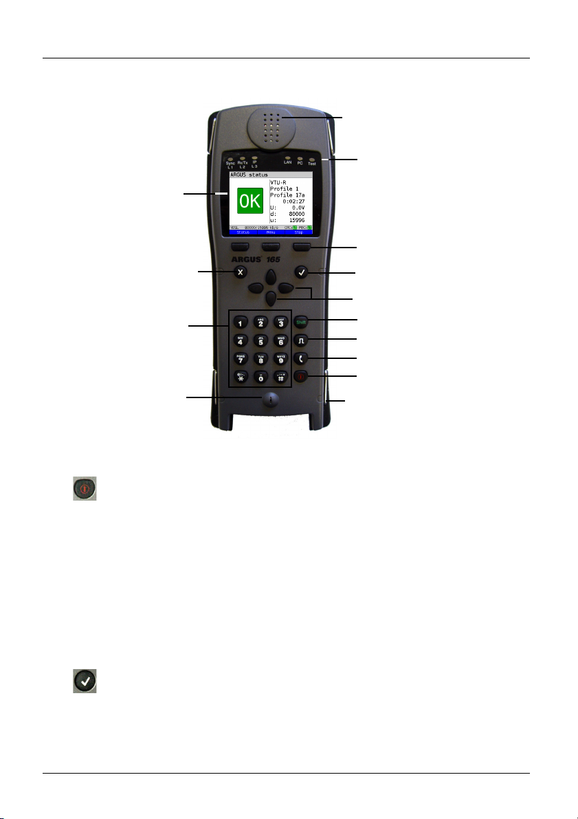
LEDs
Softkeys
Cursor keys
Enter key
Level key
Telephony: Answer/hang up
Power
Microphone
Belt clip
Number block
LC display
Back key
Shift key
Loudspeaker
Power key
-
-
-
-
-
Switches on ARGUS
Reactivation after power-down (adjustable, see page 314)
Switches on display illumination (also possible with any other key). In
battery mode, the display illumination switches off automatically after an
interval that can be set in ARGUS (see page 314).
You can open the ARGUS Manager from any point in the menu (press
briefly). Return from the ARGUS Manager to the original menu.
Switches off ARGUS (key must be held down): after an adjustable
interval (e.g. after 10 minutes), ARGUS automatically shuts down in
battery mode (see page 314).
Enter key
-
-
-
-
Opens menu
Switches to next display
Starts/opens test
Accepts setting
4 Quick-start guide
ARGUS 165
19
Page 20
4 Quick-start guide
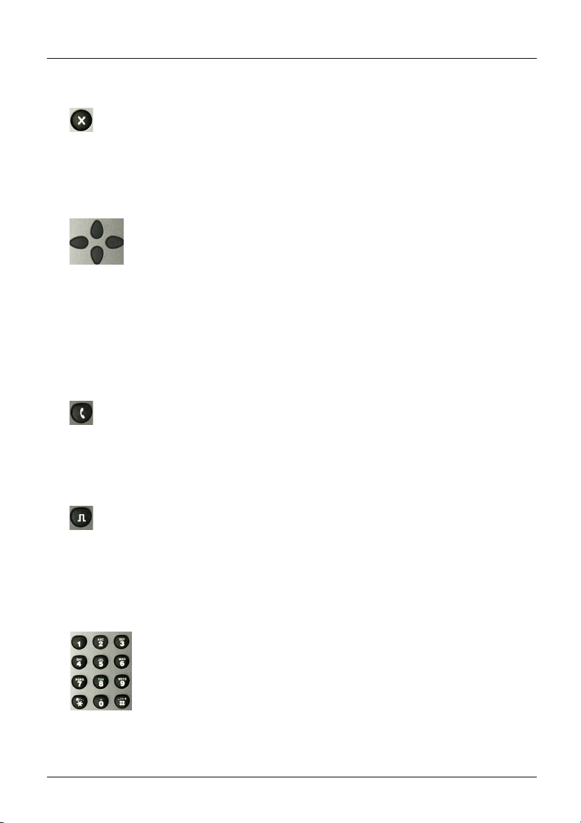
Back key
-
Switches ARGUS back to the previous display without saving current
entries, e.g. changes in a configuration parameter
-
Cancels tests
-
Exits graphic displays
-
Switches to main menu after powering up
Cursor keys
-
Brow
Cursor movement within a display line (horizontal cursor keys)
-
Within selection lists or statistics, the horizontal cursor keys can be used
-
to scroll through pages
Select a menu, a function or a test
-
Set wire types during the RC measurement
-
Move display cursor in graphic displays
-
Select functions in graphic status screen
-
Telephony
ISDN and POTS
--Answers and han
Simplified single call: press the handset key twice (ISDN only)
xDSL (access mode xTU-R, xTU-R Router) and Ethernet
- Starts VoIP telephony
evel key
L
-
Opens the grap
BRI, PRI, U-interface access: starts single-layer measurement (level/
-
voltage)
xDSL access: displays results
-
Ethernet: opens results
-
Start/stop function for realtime analyses (Line Scope / TDR)
-
Number block
-
Entry of nume
Direct function call, depending on the selected access (hot key), e.g.
-
page 324 et seq.
ses display lines page by page (vertical cursor keys)
gs up
hic status screen
rals 0 through 9, letters and special characters
20
ARGUS 165
Page 21
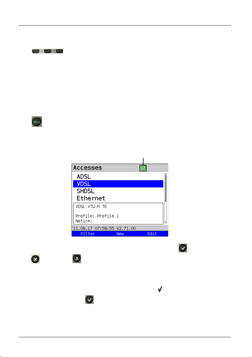
Softkeys
Example:
Press Shift to change
the softkey assignment.
Shift key
4 Quick-start guide
-
The function
The currently assigned function appears in the bottom line of the display
in the form of three blue fields with white letters, e.g.:
<Menu>: opens main menu
<Start>: establishes a connection or starts a test
Other softkeys are described in the corresponding chapters of this
-
manual.
In some menus, a green "S" in a green circle appears in the top line of the
display.
In these menus, the softkeys are assigned two functions. The Shift key
toggles the softkey assignment (see example page 201).
of the three softkeys depends on the respective situation.
ARGUS is mainly controlled using the four cursor keys, the Enter key , the Back key
, the Level key and the three sof
The bottom line of the display shows the current softkey assignments.
tkeys.
In the following pages of this manual, only the respective currently valid sof
displayed in angle brackets
< > , e.g. <Menu>. The softkey < > performs the same
tkey function is
function as the Enter key .
ARGUS 165
21
Page 22
4 Quick-start guide
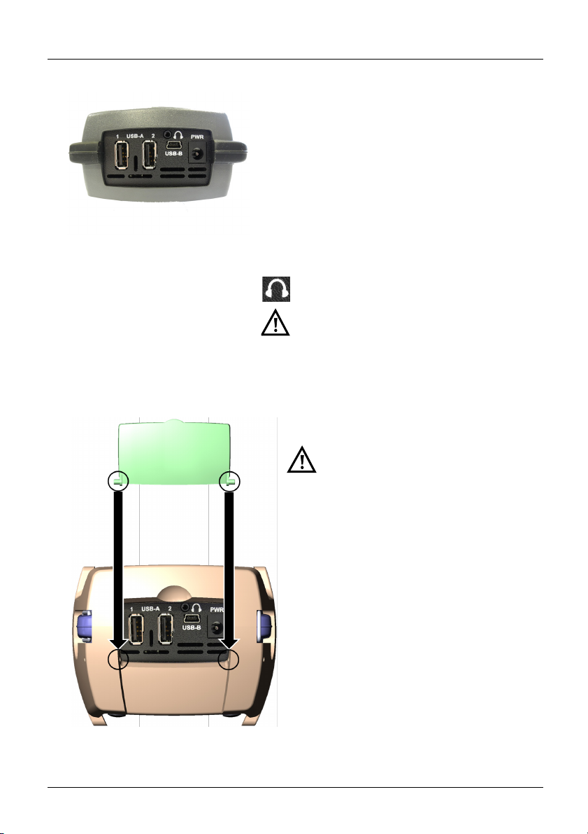
PWR
For external power adapter.
When the external power adapter is connected,
ARGUS switches off the battery power supply.
USB-A or USB-A 1/2
USB-host interface
(Active Probe II, Copper Box, WLAN, LTE)
USB-B (mini-USB)
USB-client interface (PC connection)
Headset socket
ARGUS check regularly if there are any
USB devices connected.
Using the ARGUS socket cover with the rubber protective sleeve
First fit the rubber protective sleeve, then
insert the socket cover in the two
recesses in the sleeve provided for that
purpose.
The socket cover does not completely
protect ARGUS against water or dirt
penetration.
Open or remove the cover when using
the device continuously over longer
periods to prevent internal heat build-up.
Disconnect all connected devices before
using the socket cover.
Top connections
22
ARGUS 165
Page 23
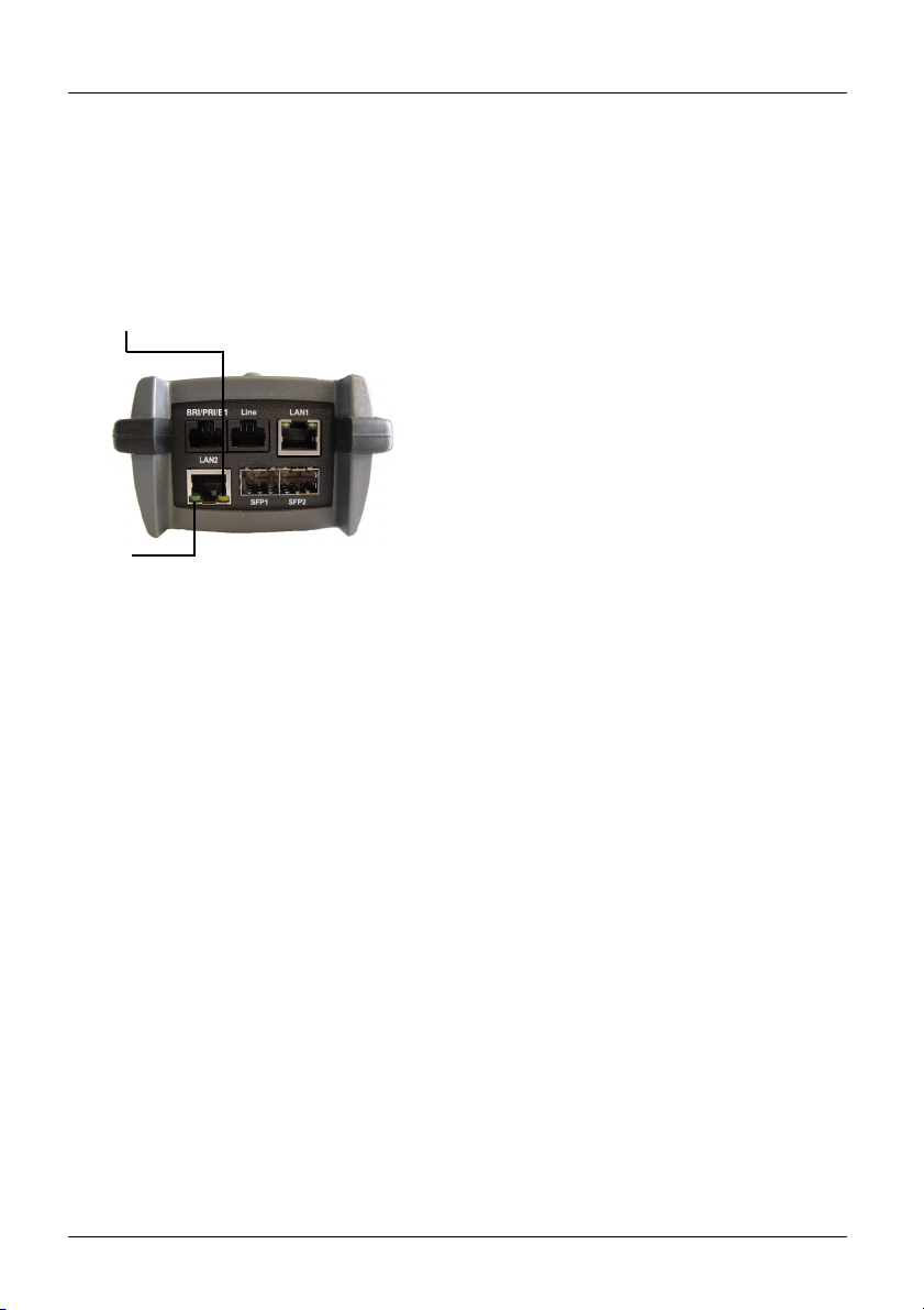
Bottom connections
Yellow Link/Data LED:
signals physical connection with another
Ethernet port
- LED steadily illuminated:
connecting
- Flashing LED: transmitting/
receiving
BRI/PRI/E1
Access BRI
Access PRI
Pin assignment: 3/6, 4/5
1
Pin assignment: 1/8, 2/7
1
Line
Access POTS
Access U-interface
Access xDSL
SHDSL n-wire
Access Copper
Pin assignment: 4/5
Pin assignment: 4/5
1
Pin assignment: 4/5
Pin assignment: fixed 4/5
variable 3/6, 1/2, 7/8
Pin assignment: 4/5
LAN1 and LAN2
Connection to a PC network card.
Connection to the Ethernet interface of an xDSL
modem, router (IAD) or hub/switch or another
Ethernet interface (access: Ethernet).
SFP1 and SFP2
Connection of selected SFP modules from various
manufacturers, for accessing fiber-based interfaces
(Ethernet, FTTx/GPON).
SFP2 is optional and must be enabled separately.
Therefore, always use SFP1 for single-port
applications.
The green Speed LED and yellow Link/
Data LED indicate transmission speed
- LED on: 10/100 Base-T
Green Speed LED indicates transmission
speed
- LED on: 10/100/1000 Base-T
4 Quick-start guide
ARGUS 165
23
Page 24
4 Quick-start guide
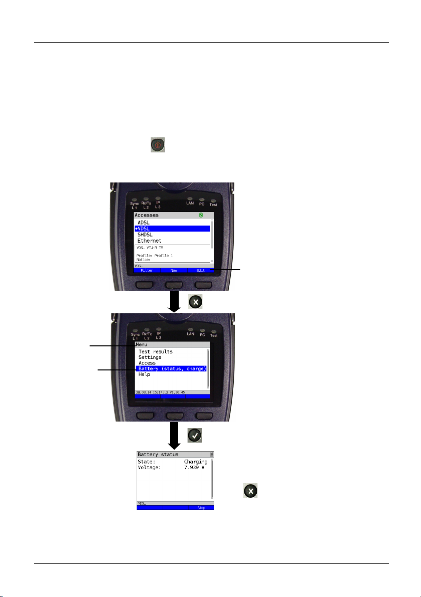
Current assignment of the softkeys.
Press
ARGUS indicates in the display when
the battery is completely charged.
Press: ends charging.
The Accesses display can vary
depending on the configuration.
Selected
menu option
Menu name
Charging the battery in initial operation
The battery pack compartment is on the rear of the device. Attach the battery back by
placing it against the retaining points at the top end and then screwing down the knurled
screw. Use only the battery pack supplied with the device. Observe the safety information
given on page 15. Now connect your (switched-off) ARGUS to the external power supply
supplied with the device.
Switch on ARGUS using the key. The following display appears (you may first need to
acknowledge warnings or messages with
<Continue>):
You must first change the battery pack supplied with the device completely (see page 322
Status) before full capacity is reached.
24
ARGUS 165
Page 25
4 Quick-start guide
Power-saving mode
In battery mode, ARGUS automatically switches off after five minutes of no activity
(interval adjustable, see page 314). ARGUS does not switch off during a test e.g.
(Loopbox) or in trace mode.
The device can alternatively be operated using the supplied external adapter. When the
adapter is connected, power supply via the battery is automatically switched off. ARGUS
must always be operated with the battery, regardless of the power supply type. This
ensures e.g. uninterrupted operation of the real-time clock.
Unplug the adapter from the mains as soon as ARGUS is switched off and
no longer in use (battery charging).
ARGUS 165
25
Page 26

4 Quick-start guide
26
ARGUS 165
Page 27
5 Configuring accesses
Switch on ARGUS.
Continued on
next page
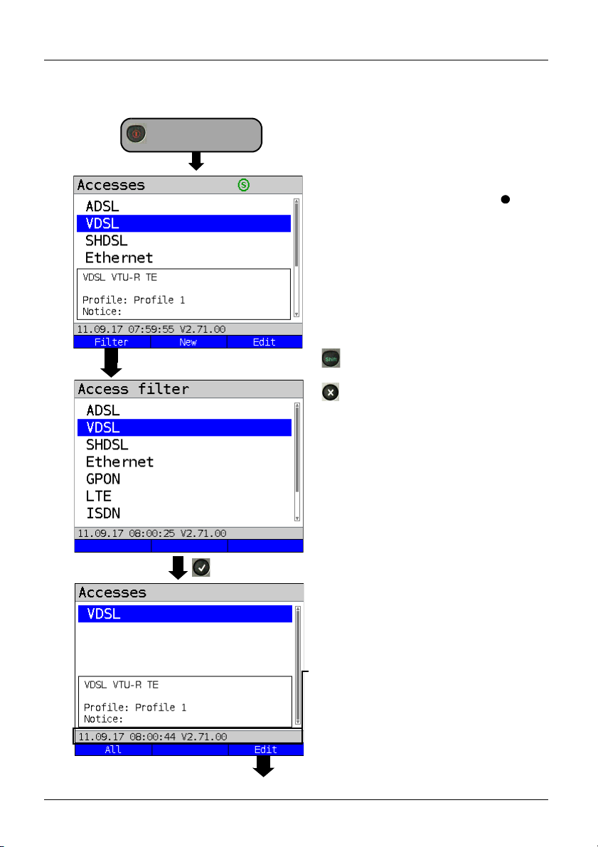
5 Configuring accesses
After powering up, ARGUS displays all
configured accesses (up to 100). By
d
efault, one access is preconfigured for
every interface type (ADSL, VDSL, ...).
When changing accesses, the last access
used is indicated on the display with
ARGUS additionally displays a preview of
he selected access settings, see also
t
page 32. The preview window opens after
2 seconds.
<New>
Creates an access, see
page 28, Fig. 2.
<Edit>
Edits an access, see page 28,
Fig. 1.
Toggles softkey assignment,
age 35.
see p
Switches to main menu.
With the <Filter> softkey, ARGUS lets
you filter all pre-configured accesses
according to access type (ADSL, VDSL,
...) and displays this group.
.
ARGUS 165
In this example, VDSL is selected.
All relevant accesses are displayed in
w
hich VDSL is specified in the confi-
guration.
The status line (above the softkey)
displays either the date, time, version and
b
attery level after power-up, or the access
“still” selected after changing accesses..
<All>
Display of all possible accesses,
see Fig. 1.
<Edit>
Edits the selected access profile.
27
Page 28
5 Configuring accesses
Continued on
next page
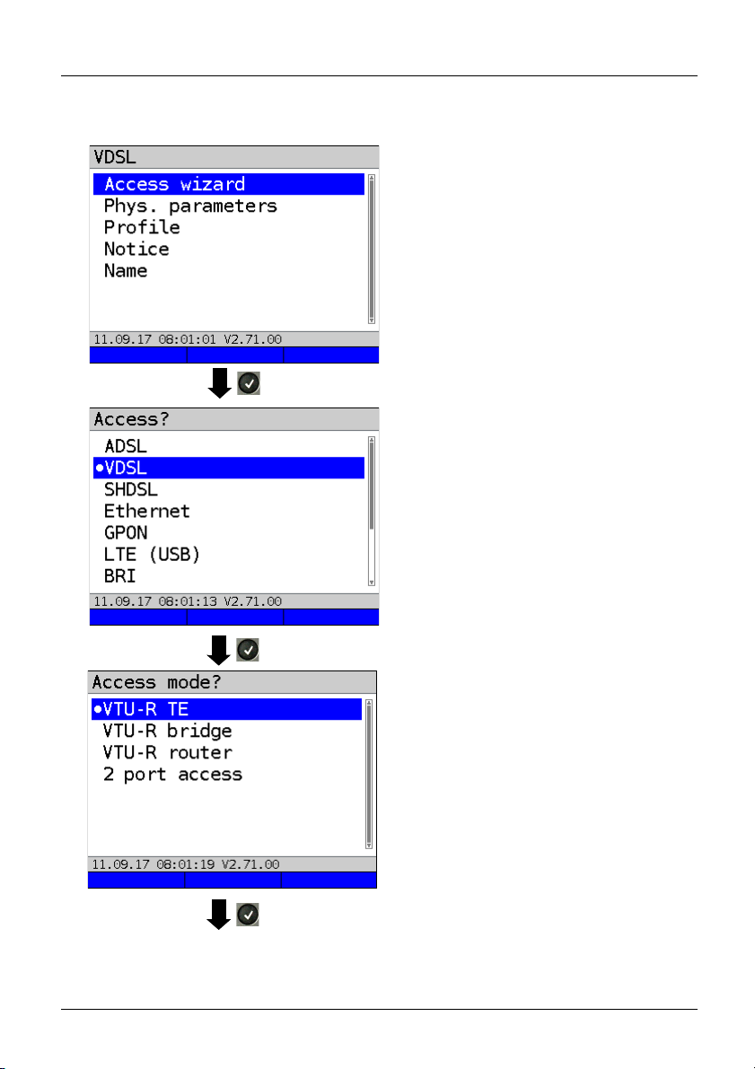
5.1 Access wizard
ARGUS switches to the "Accesses" main
menu.
You can now configure the selected
access, her
wizard.
The query parameters of the access
wizard depend on the selected access
(ADSL, VDSL, ...), see page 32.
Selection of physical interface (here
VDSL).
- For xDSL, see page 41.
- For Ethernet, see page 85 and Gigabit-
Ethernet Manual.
- For BRI, see BRI Manual.
- For POTS, see page 240.
- For Copper tests, see page 252 and
ARGUS Copper Box Manual.
e VDSL, using the access
28
ARGUS switches directly to t
mode settings.
Selection of access mode (here VDSL
VT
U-R terminal) device).
- For xTU-R TE, see page 54.
- For xTU-R bridge, see page 80.
- For xTU-R router, see page 82.
- For 2 port access, see GigE Manual.
- For STU-C, see page 84.
he access
ARGUS 165
Page 29
Continued on
next page
5 Configuring accesses
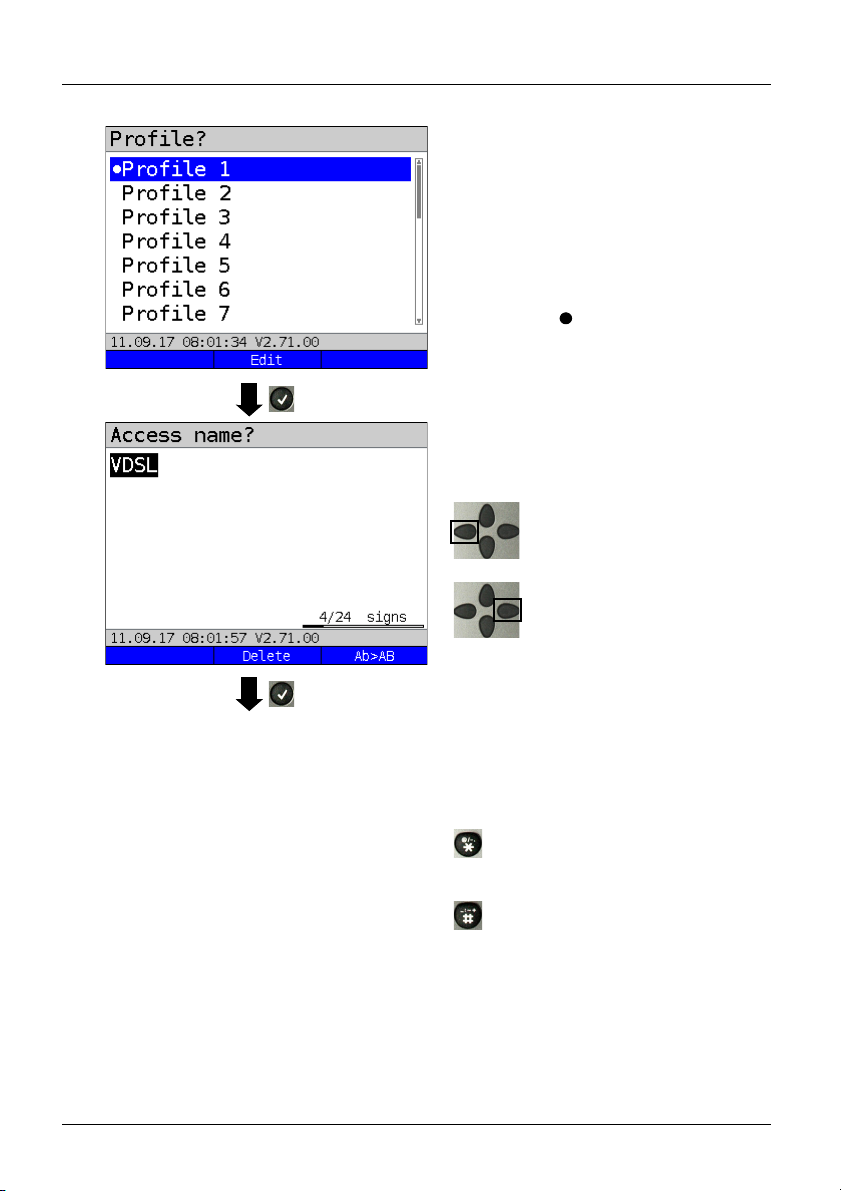
You can now link your configured
access settings with one of 20 profiles.
hese profiles link the access settings
T
with the access and test parameters. You
can define service, virtual line and other
parameters.
The selected profile is highlighted in the
d
isplay in blue. The default profile is
indicated with a
Once you have selected the profile,
ARGUS suggests an access name, based
on the settings you made previously (here
VDSL). You can enter up to 24 characters
(in this example 04/24 characters).
<Delete>
in the display.
Deletes access name.
Clears mark and returns cursor
keys to the start.
Clears mark and returns cursor
keys to the end.
ARGUS 165
<Ab>AB>
<AB>12>
<12>ab>
<ab>AB>
Entry begins with upper-case
letters and continues in lowercase.
Entry of upper-case letters.
Entry of numbers.
Entry of lower-case letters.
Entry of special characters,
e.g. @, /, -, ., *, ?, %, =, &, !
etc.
Entry of special characters
e.g. _, :, +, # etc.
29
Page 30
Continued on
next page
2x
5 Configuring accesses
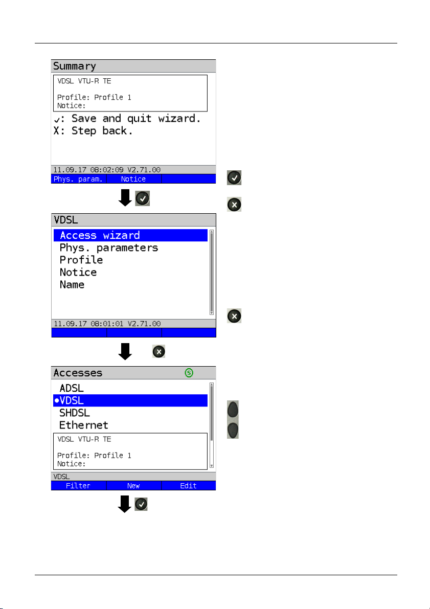
ARGUS displays a summary of the
configuration.
<Phys.
param.>
<Notice>
Edits the physical
parameters, see page 43.
Entry of notices, see
page 38.
Save and exit the wizard.
Go back one level.
ARGUS returns to the editing overview of
the selected access (here VDSL).
To configure the services or test parameters, select "Profile"; see also page 36.
You need to exit the access wizard before
ARGUS can use the configured a
ccess.
Exit the access wizard.
30
Select access.
Press OK to confirm the selected access,
here VDSL.
ARGUS 165
Page 31

5 Configuring accesses
ARGUS switches to the ARGUS status
display.
<Status>
<Menu>
<Start>
Switches to status screen.
Switches to main menu.
Starts the VDSL connection.
ARGUS 165
31
Page 32

5 Configuring accesses
ARGUS access wizard
The access wizard prompts for different infor
Each parameter queried depends on the respective previous parameters (from left to right).
Access/
inte
rface
Line (PIN,
only LTE)
Mode Access mode L2 mode Ethernet
ADSL - Annex A
Annex B
..
VDSL - - VTU-R TE,
SHDSL 2-, 4-,
6-, 8-wire
ATM,EFM,
TDM,
HDLC,
ATM/EFM
automatic
Ethernet LAN 1, 2
- IP based,
SFP 1
LTE PIN -
BRI - - TE, NT,
U-interface - - TE,
PRI - - TE, NT,
POTS - - Terminal,
Copper tests - - - - - -
1
=only for BRI-TE, U-interface-TE *2 = only for LAN1
*
mation depending on the access/interface.
ATU - R T E,
- LAN 1,2
ATU - R bridge ,
.
ATU-R router,
2 port access
- LAN 1,2
-R bridge,
VTU
VTU-R router,
2 port access
ITC,
STU-R, STU-C,
-R bridge,
STU
- LAN 1,2
STU-R router,
STU-C bridge,
2 port access
cable test*
2
2 port access*
-
le
ased line,
monitor
leased line
,
- - Profile
2
- - Profile
Auto.*
P-P,
P-MP
Auto.*
P-P,
P-MP
- - -
ased line,
le
monitor
- - -
or
monit
1
,
1
,
interface
Profile
Profile
SFP 1
Profile
SFP 1
Profile
SFP 1
- -
- -
32
ARGUS 165
Page 33

For ADSL access, you are prompted for ADSL mode:
Description
ADSL mode
Different ASDL modes can be set depending on the variant. The set
ADSL mode must be compatible with the ATU-C (network side). When
ADSL auto-modes "Annex A/M auto, Annex B/J auto, Annex A auto,
Annex B auto and Annex M auto" are selected, ARGUS automatically
detects and matches the configuration on DSLAM.
Default: Annex A/M auto
5 Configuring accesses
A TC sublayer is queried for the SHDSL access. ARGUS suppor
mission convergence) sublayer
s:
ts the following TC (trans-
Description
ATM Like ADSL, asynchronous transfer mode (ATM) is based on asynchronous time
multiplexing. The sender and receiver can run at different clock rates so as to
serve both packet-switched (IP) and circuit-switched data traffic with a single
transmission technology. ATM enables this by means of an intermediate layer
with cells of a fixed size (precisely 53 bytes) between the network and data link
layers. These ATM cells are filled with the incoming data and prioritised with the
help of the ATM adaptation layer (AAL). Data are transported in AAL5 and speech
in AAL1 or 2. This ensures that speech is not delayed. Type, duration and other
transmission information are stored in a 5-byte header, which reduces the
payload of a cell to 48 bytes. This technology offers a range of advantages thanks
to its various OAM management functions and AAL adaptation capabilities.
However, this consumes an overhead. Still, this technology, which enables a
bandwidth of up to 2.304 Mbit/s via a twisted pair, remains in wide use, though no
longer rolled out as frequently. It is mainly used for speech and data transmission.
Default: ATM
EFM Ethernet first mile (EFM) helps to reduce the ATM overhead and results in a
higher net data rate. EFM allows Ethernet frames to be transmitted directly
without being bundled in ATM cells, and is specified in IEEE 802.3ah. This
process exploits the fact that the IP packets received from the network are simply
passed through along the last mile and distributed to the terminal devices at the
local loop. EFM forwards the Ethernet frames directly from DSLAM, without
packing them in smaller ATM cells. This reduces the overhead entailed in
additionally transmitting headers and in packing and unpacking the frames in ATM
cells for every data exchange. As the packet-switched data portion is becoming
ever greater and IP-based speech transmission (VoIP) has reached a high quality
level, EFM is being increasingly expanded. The main area of application is thus in
transmission of IP packages and therefore primarily data.
ARGUS 165
33
Page 34

5 Configuring accesses
TDM Time division multiplex (TDM)
If only a single digital permanent circuit, such as an E1 access, must be replaced,
TDM technology is a natural choice. This time division multiplex process enables
the available bandwidth to be divided into 64 kbit timeslots, thus providing up to
36 B-channels simultaneously for telephony. This results from the maximum
bandwidth of 2.304 Mbit/s that SHDSL can provide. It thus offers four B-channels
more than a conventional E1 access, without the need for a complete twisted pair.
The telephony quality via the B-channels is equivalent to that of ISDN. Its main
area of application is thus speech transmission. TDM is still widely used.
ITC Independent transmission convergence (ITC) is the name of a special ARGUS
mode. In this mode, ARGUS attempts to establish a synchronisation – if only
briefly – independently of the TC sublayer used (ATM, EFM or TDM) by means of
special commands. Its main purpose is to test whether a specific access is an
SHDSL access. This mode is not intended for permanent connections or data
transmission.
HDLC High-level data link control (HDLC) is a unique ARGUS mode that enables
synchronisation with remote stations (e.g. net-to-net type) of specific
manufacturers. This mode is not intended for permanent connections or data
transmission.
ATM/
EFM
auto-
matic
When ATM/EFM automatic is selected, ARGUS first establishes a 2-wire
connection and then determines the TC sublayer used with the aid of the received
signals. Once the TC sublayer is identified, the remaining configured wire pairs
are connected.
34
ARGUS 165
Page 35

Sorting the accesses in the access overview
5 Configuring accesses
Press one after
another
and
In order to keep frequently used accesses
readily available, ARGUS allows you to
arrange the configured accesses in any
order.
Switches to softkey assignment.
Shortcut to access
selection menu.
5.2 Phys. parameters
<>
The selected access is
moved down one place in
the list.
<>
The selected access is
moved up one place in the
list.
<Delete>
Deletes the highlighted
cess.
ac
Edits the physical parameters of the
selected access (here VDSL, see
page 43).
The physical parameters can also be
o
pened and edited directly when the
access wizard is finished (see page 30
Fig. 1).
ARGUS 165
35
Page 36

5 Configuring accesses
Continued on
next page
5.3 Profile
The preconfigured accesses can be linked
p to 20 profiles.
to u
These profiles link the ac
with the access and test parameters. You
can set various parameters here including
those for service and virtual line.
Select a profile.
ARGUS enables configuration of up to 20
pr
ofiles.
Select the profile you wish to edit.
T
he selected profile appears in the
display in blue. The default profile
is indicated with a in the display.
cess settings
36
Select e.g. Ser
parameters.
Services page 114 et seq.
Bridge/router, see page 80.
Profile name: Enter the name of the
s, see page 29.
acces
vices or Test
ARGUS 165
Page 37

5 Configuring accesses
Test parameter settings are
described starting on page 124.
ARGUS 165
37
Page 38

5 Configuring accesses
5.4 Notices
In the preview, ARGUS shows not only the
selected access, the xDSL mode and the
access mode but also a freely editable
notice (see Fig. 1 page 30).
This note can be up to 28 characters long.
In this example, the note "Using VLAN" is
selec
ted.
<Delete>
Deletes notice.
Clears mark and returns cursor
keys to the start.
Clears mark and returns cursor
keys to the end.
<Ab>AB>
Entry begins with upper-case
letters and continues in lowercase.
<AB>12>
<12>ab>
<ab>AB>
Entry of upper-case letters.
Entry of numbers.
Entry of lower-case letters.
Entry of special characters, e.g.
@, /, -, ., *, ?, %, =, &, ! etc.
Entry of special characters
such as _, :, +, # etc.
Press OK to save the entered notice.
You can subsequently edit the access
name
as described for the access
assistant, see page 29.
38
ARGUS 165
Page 39

5 Configuring accesses
The saved notice is linked with the access
and is displayed in the preview.
The preview appears approx. 2 seconds
a
fter the access is selected.
<Filter>
ARGUS switches to the Filter
menu, see page 27.
<New>
<Edit>
Creates a new access.
Edits access.
Selects access
Switches to ARGUS status, see page 32.
<Status>
<Menu>
<Start>
Switches to status screen.
Switches to main menu.
Starts the VDSL connection.
ARGUS 165
39
Page 40

6 Physical layer
Services,
see
page 114
Layer 1
Router/bridge
(only for xTU-R bridge
and xTU-R router)
Virtual lines
see
page 93.
Profile name
Current
access and
softkey
assignment
Press Level key or
<Status>
See page 43
See page 27
See page 55
Fig. 2 (example VTU-R router):
Fig. 1
6 Physical layer
The physical layer (layer 1) is shown in the status screen (Fig. 2) with its own graphical
element (here VDSL). The other elements in the status screen are initially only named. This
is explained in more detail on page 93 (Virtual Lines) and page 114 (Services). The phys-
ical layers for the ADSL, SHDSL and Ethernet interfaces are presented in the same way as
for VDSL. The selection of the VDSL access and the access mode VTU-R are directly
adopted in the status screen. If the defaults are correct, layer 1 (synchronisation on VDSL)
can be established directly on
and modem states (power down) are displayed in the layer-1 box (blue). To change the
VDSL configuration directly, press
screen (Fig. 2), press the softkey
See page 116 for tests that can be run via layer 1.
<Start>. The most important information such as voltage (U)
<Edit>. To change the access type directly in the status
<Access> or the key combination plus .
<Edit>
<Access>
<Start>
Modify VDSL
configuration
Access selection
Synchronise
40
ARGUS 165
Page 41

7 Operation on xDSL accesses
7 Operation on xDSL accesses
ARGUS supports the following DSL interfaces: ADSL, VDSL, SHDSL
ARGUS supports the following access modes on xDSL accesses:
xTU-R Terminal device mode (xDSL transceiver unit) see page 54.
ARGUS is connected to the xDSL access (in front of or behind the
splitter). ARGUS replaces the modem and PC.
xTU-R bridge Bridge mode (xDSL transceiver unit bridge) see page 80.
ARGUS is connected to the xDSL access and the PC.
ARGUS replaces the xDSL modem (for SHDSL only ATM and EFM).
xTU-R router Router mode (xDSL transceiver unit router) see page 82.
ARGUS is connected to the xDSL access and the PC.
ARGUS replaces the xDSL modem and router (for SHDSL only ATM
and EFM).
STU-C (STU-C: SHDSL Transceiver Unit-Central Office).
ARGUS simulates the central office side (DSLAM).
The individual DSL tests record and store data (e.g. traces of IP data). It is the
user's responsibility to comply with the applicable legal requirements.
The line may not carry a DC voltage greater than 200 V DC and should be free of
AC voltage components.
In principle, the operating temperature range set out in "Technical data" (see
page 17) applies for SHDSL operation. For ambient temperatures just below
+50 °C, extended operation in high-performance modes can trigger the
temperature dependent ARGUS protection functions described in the safety
information (see page 12).
ARGUS 165
41
Page 42

ARGUS status screen:
Layer-1 box (blue in display) selected.
<Edit> Opens settings
Status screen
Status screen:
Display (from top to bottom)
- Access mode (in this example: VTU-R)
- Previous profile (in this example: profile 1)
- Modem state (in this example: power down)
- DC voltage on the interface
VDSL test not yet started:
Meaning of LED image in display:
Red LED: No test started
Yellow LED: Test started
Green LED: Connected
<Menu> Switches to main menu, see
menu tree
<Status> Switches to status screen
see page 55
Main menu, see menu tree
Note: accessing functions via number keys/key combinations
You can call important functions/tests directly using the keys of the ARGUS keypad. You
can find an overview of these key combinations on page 116.
7 Operation on xDSL accesses
7.1 Configuring the xDSL interface
42
ARGUS 165
Page 43

7 Operation on xDSL accesses
7.2 xDSL settings
ARGUS stores all relevant settings (e.g. set and limit values) for a test with the accesses.
Only the relevant settings are applied, depending on the test situation. You can restore the
default settings at any time (see page 318):
Setting Description
Phys. parameters:
ADSL:
Rated /
treshold
value
Setting
Bitrate
CRC limit
value
FEC limit value Determines the maximum FEC (forward error correction)
HEC limit value Determines the maximum HEC (header error correction)
Entry of the comparison value for the upstream and
downstream ATM bitrate [kbit/s] using the number keys.
ARGUS displays a large green "OK" in the ARGUS status
screen if the current bitrate is above the set value for an
active DSL connection and an "OK" for connection
parameters below the target, otherwise "NOK".
Default: d: 0 and u: 0
Sets the max. CRC (cyclic redundancy check) value.
ARGUS displays a large green "OK" in the ARGUS status
screen if the current value is below the set limit value for
an active DSL connection and an "OK" for connection
parameters below the target, otherwise "NOK".
Range: 0 to 999,999,999
Default: far: * and near: * (*=off)
value.
ARGUS displays a large green "OK" in the ARGUS status
screen if the current value is below the set limit value for
an active DSL connection and an "OK" for connection
parameters below the target, otherwise "NOK".
Range: 0 to 999,999,999
Default: far: * and near: * (*=off)
value.
ARGUS displays a large green "OK" in the ARGUS status
screen if the current value is below the set limit value for
an active DSL connection and an "OK" for connection
parameters below the target, otherwise "NOK".
Range: 0 to 999,999,999
Default: far: * and near: * (*=off)
ARGUS 165
43
Page 44

7 Operation on xDSL accesses
INP/SNRM
Determines whether preference is to be given to INP (inpulse noise
protection) or SNRM (signal-to-noise- ratio margin) when an ADSL
connection is established.
Default: Favour DS SNRM
Retrans-
mission
(G.INP)
When retransmission (G.INP, G.998.4) is used, the downstream of ADSL
links is protected against pulse noise on layer 1. Delays and packet losses
are minimised; however, this increases the interleave delay for
downstream.
Default: Down- & Upstream
When Retransmission (G.INP) is active, ARGUS shows in the status line a
„R“ for Retransmission.
When Retransmission (G.INP) is unlocked but not active, ARGUS shows in
the status line a „R“ for Retransmission.
MAC address (line)
(not available using the access wizard)
Display and selection of the line MAC addresses.
The first two MAC addresses cannot be manually edited.
1. When the standard MAC address is selected, ARGUS uses its own
MAC address.
Default: Standard MAC address
2. When you select the dynamic MAC address, a different MAC address
is used each time the device synchronises.
3. You can enter a third MAC address:
Mark the line and then press
<Edit>
Entry of new MAC address.
<Edit>.
The address is entered in hexadecimal form using the
number keys and key combinations: *1=A, *2=B,*3=C,
*4=D, *5=E, *6=F and confirmed with .
No group MAC addresses may be used.
Default: 00:00:00:00:00:00
Accepting the address.
The new address is temporarily saved, and is no longer
available after powering down.
Press one after
another
Display of ARGUS MAC addresses:
Line, LAN, SFP, ETH, see also page 324 and following.
44
and
ARGUS 165
Page 45

VDSL:
Rated /
treshold
value
7 Operation on xDSL accesses
The setting “Dynamic MAC address” is active across all interfaces. For
instance, if the setting for ADSL is changed, this also affects the MAC
address for VDSL, SHDSL or Ethernet. Dynamic MAC addresses are used
here as well. The setting “Dynamic MAC address” is saved.
Every service (see page 114) is connected to the physical layer (see
page 40) via its own virtual line (see page 93) uses its own MAC address.
If the setting “Standard MAC address” is used, this is made up as follows:
Voreinstellung: 00:12:A8:EX:XX:XX
The first three blocks (00:12:A8) do not change, as these stand for intec
GmbH. The fourth block (EX) changes depending on the selected interface
and service, provided that this uses its own virtual line. The final two blocks
(XX:XX) depend on the device type and serial number.
00:12:A8:E0:XX:XX Data service via Ethernet or GPON
interface.
00:12:A8:E1:XX:XX Data service via a xDSL interface
(ADSL, VDSL, SHDSL).
00:12:A8:E3:XX:XX VoIP service via Ethernet or xDSL
interface.
00:12:A8:E4:XX:XX IPTV service via Ethernet or xDSL
interface.
00:12:A8:E5:XX:XX VoD service via Ethernet or xDSL
interface.
Setting bitrate Entry of the comparison value for the upstream and
downstream bitrate [kbit/s] using the number keys.
ARGUS displays a large green "OK" in the ARGUS status
screen if the current bitrate is above the set value for an
active DSL connection and an "OK" for connection
parameters below the target, otherwise "NOK".
Default: d: 0 and u: 0
CRC limit
value
Sets the max. CRC (cyclic redundancy check) value.
ARGUS displays a large green "OK" in the ARGUS status
screen if the current value is below the set limit value for
an active DSL connection and an "OK" for connection
parameters below the target, otherwise "NOK".
Range: 0 to 999,999,999
Default: far: * and near: * (*=off)
ARGUS 165
45
Page 46

7 Operation on xDSL accesses
FEC limit value Determines the maximum FEC (forward error correction)
value.
ARGUS displays a large green "OK" in the ARGUS status
screen if the current value is below the set limit value for
an active DSL connection and an "OK" for connection
parameters below the target, otherwise "NOK".
Range: 0 to 999,999,999
Default: far: * and near: * (*=off)
Firmware
Carrier set The carrier set determines the carrier frequencies that ARGUS uses to
Vectoring
mode
Selects the firmware (FW) in the VDSL chipset.
You can choose between version A and version B.
Further information is available on request.
Default: A
signal to DSLAM that it is ready to synchronise (ITU G.997.1).
The carrier generally specifies which sets are to be used.
You can select the following sets with corresponding upstream tones (inter-
val between tones 4.3125 kHz) in ARGUS:
- A43, tones: 9, 17, 25
- B43, tones: 37, 45, 53
- V43, tones: 944, 972, 999
Default: A43, B43, V43
When multiple sets are selected, ARGUS cyclically transmits the tones of
the selected sets in parallel.
Vectoring mode defines how ARGUS behaves when synchronising with
DSLAM:
- Non-vectoring (off)
This is standard VDSL2 with non-vectoring-capable DSL access
multiplexers (DSLAMs) and modems. However, it can also be used for
mixed operation with non-vectoring-capable modems on vectoring-capable
DSLAMs. In such a case, the simulated modem is throttled to the ADSL2+
bandwidth (max. 16 Mbit/s).
- Full vectoring
Full vectoring operation requires vectoring-capable DSLAMs and modems.
VDSL2 vectoring is supported when this technology is present at both ends
of the bundle.
Default: Full vectoring
46
ARGUS 165
Page 47

7 Operation on xDSL accesses
Retrans-
mission
(G.INP)
When retransmission (G.INP, G.998.4) is used, the downstream of VDSL2
links is protected against pulse noise on layer 1. Delays and packet losses
are minimised; however, this increases the interleave delay for
downstream.
Default: Down- & Upstream
When VDSL Vectoring or Retransmission (G.INP) are active, ARGUS
shows in the status line a blue highlighted „V“ for Vectoring or „R“ for
Retransmission.
When VDSL Vectoring or Retransmission (G.INP=) are unlocked but not
active, ARGUS shows in the status line a grey highlighted „V“ for Vectoring
and „R“ for Retransmission.
MAC address, see page 44.
SHDSL:
Spectrum For region 1 (e.g. North America):
Annex A/F Auto, Annex A SHDSL, Annex F SHDSL.bis (5.7 Mbit/s)
For region 2 (e.g. Europe):
Annex B/G Auto, Annex B SHDSL, Annex G SHDSL.bis (5.7 Mbit/s)
Automatic selection of modulation modes:
- TC-PAM 16 (SHDSL)
- TC-PAM 32 (SHDSL.bis)
Default: Annex B/G auto
Clock/
framing
(not for
ATM + EFM)
The timing relates to the receiving and transmitting directions of a
connection. The reception and transmission timing are identical for
synchronous timing and different for plesiochronous timing. Timing
differences are compensated by means of bit stuffing.
- Synchronous
- Plesiochronous (for TDM only)
- Plesiochronous (NTR) (for TDM only)
(the SHDSL timing is derived from the network timing reference)
Default: synchronous
ARGUS 165
47
Page 48

7 Operation on xDSL accesses
Channel
selection
(not for
ATM + EFM)
Data rate
(only for
ATM + EFM)
Power
back off
EOC usage The embedded operations channel (EOC) is used to exchange connection-
Sync word The sync word identifies the SHDSL frame.
Selection of the B and Z channels via the number keys. You can select up
to 36 B channels and up to 7 Z channels. When you enter * (for the B and Z
channels), ARGUS automatically detects the channel allocation.
Maximum selection:
36 B channels and 1 Z channel
35 B channels and 7 Z channels
Minimum selection:
- 3 B channels
- 0 Z channels
Default: * (automatic)
If an auto mode is selected under Spectrum (see page 47), channel
selection is also automatic regardless of the settings made here.
Sets the data rate in kbit/s
For SHDSL
- Range: 192 kbit/s to 2.3 Mbit/s
- Default: * (automatic)
For SHDSL.bis (ESHDSL):
- Range: 768 kbit/s to 5.7 Mbit/s
- Default: * (automatic)
If an auto mode is selected under Spectrum (see page 47), data rate
selection is also automatic regardless of the settings made here.
Reduces the transmitting power of the remote station. The set value
corresponds to the maximum transmitting power.
Range: 0 dB to 30 dB
Default: 0 dB
related and other information.
off: No queries or responses are sent to the remote station.
on (passive): No parameters are displayed at the remote station, as
on (active): The own performance parameters and those of the
Default: on (passive)
(cf. ITU-T G.991.2 Chapter: PMS-TC layer functional characteristics).
To enter the sync word, use the number keys and key combinations *1=A,
*2=B,*3=C, *4=D, *5=E, *6=F and then confirm with .
Default: 3F 16 1F 03 3C 0C
only queries are responded to.
remote station are displayed, provided that the remote
station also supports own queries.
48
ARGUS 165
Page 49

7 Operation on xDSL accesses
Message
mode
Selects the message mode. The message mode determines initiation of
the handshake on the STU-R side resp. the response on the part of the
STU-C (cf. ITU-T G.994.1 Chapter: Transactions, entry in the capability
list).
Range: GHS Mode A to GHS Mode D
Default: GHS mode C
Vendor info
field
Entry of vendor information in the corresponding transmission field. This
information is entered in hexadecimal form, see "Sync word".
Default: 15 35
Wire pairsFor 2-wire SHDSL, ARGUS always uses the wire pair 4/5 (line 1); for
SHDSL n-wire, ARGUS always uses the wire pair 4/5 (line 1) plus a further
wire pair (line) from the list.
You can change the order of the wire pairs.
- 2nd wire pair (line 2) for 4-wire
- 3rd wire pair (line 3) for 6-wire
- 4th wire pair (line 4) for 8-wire
Wire pair 4/5 (line 1) is always reserved as the master.
You can mark the 2nd, 3rd and 4th wire pairs (lines 2-4) and move them
down one slot the list using the left softkey
using the right softkey
<>. Confirm your entry with .
<> or up one slot in the list
The following default is common:
Line 1: wire pair 4-5 (fixed)
Line 2: wire pair 3-6
Line 3: wire pair 1-2
Line 4: wire pair 7-8
Line
probing
(PMMS)
When a connection is being established, line probing (power measurement
modulation session) can occur; this is standardised according to ITU-T
G.991.2. This function enables determination of a variety of line parameters
to identify the possible data rate before the actual synchronisation process
with the remote station.
ARGUS 165
49
Page 50

7 Operation on xDSL accesses
Interop
bits
Rate-adaptive
mode
This determines what interference is taken into account in
the PMM session.
- Current SNR DS: current line interference in down
stream is taken into account.
- Worst case G.991.2 SNR DS: reference line interfer-
ence from G.991.2 in downstream is taken into account.
- Current SNR US: current line interference in upstream
is taken into account.
- Worst case G.991.2 SNR US: reference line inter-
ference from G.991.2in upstream is taken into account.
Default: none
<Add>
A display with the available modes opens. Any mode
marked with in this window is inserted in the list
(above the mode marked in the list).
<Delete>
Deletes the marked mode from the list
Adopts the mode priorities.
Targets SNRm
in dB
Destination SNR margins can be set for the above line
interference.
- Current up: 0
- Current down: 0
- Worst-case up: 0
- Worst-case down: 0
Range: -10 dB to 21 dB
Default: zero for all
Line probing The PMM session supports the following remote stations:
- G.991.2
- Globespan
Default: G.991.2
Multiwire
(only for ATM +
TDM)
The synchronisation behaviour is matched to the following
remote stations:
- Auto (automatic)
- Globespan
- G.991.2
Default: auto
50
ARGUS 165
Page 51

EFM Aggregation Select this setting when ARGUS in
SRU
(EFM and
Independent
ITC only)
EOC
error counter
QD2Lite Determines wheter the protocol uses QD2Lite in EO
MAC address, see page 44.
7 Operation on xDSL accesses
STU-C mode and the modem in STU-R
mode do not support the discovery
operation of the expanded G.hs
according to IEEE 802.3ah section 4.
Discovery and
agg.
Default: Discovery and agg.
Supports the regeneration unit (SRU) functions of the
following remote stations:
- Off
- Elcon Coco10M (only EFM)
- Elcon International (only EFM)
- Albis BSRU (only for 4-wire Independent TC)
Default: Off
Depending on the setting here, errors are transmitted
using the EOC, summed by ARGUS ("absolute") and
displayed or determined over the corresponding request
interval ("delta") and displayed.
Default: Delta
channel or not.
Default: off
Select this setting when the discovery
operation of the expanded G.hs
according to IEEE 802.3ah section 4 is
supported.
ARGUS 165
51
Page 52

7 Operation on xDSL accesses
Status screen:
ARGUS in Status screen, in this example
ADSL router mode is selected.
<Edit> Open settings
Profiles (
<Edit> edit profiles)
Bridge/Router
IP version
(Bridge +
Router)
IPv4
(Bridge +
Router)
Determines which IP version is to be used.
IPv4:
IPv6:
Dual Stack
IPv4/IPv6:
Internet Protocol version 4 acc. to RFC 791
Internet Protocol version 6 acc. to RFC 2460
If IPv6 is available, this protocol is preferred; if not,
ARGUS switches to IPv4.
Default: IPv4
Definition of IP address assignment
IP mode: Static IP:
DHCP server:
Fixed IP address
Assignment of IP address by ARGUS
Default: DHCP server
Own IP
Address:
Range: Range 0.0.0.0. to 255.255.255.255
Default: 192.168.10.1 (assignment see RFC 3330)
IP netmask: Range: Range 0.0.0.0. to 255.255.255.255
Default: 255.255.255.0 (assignment see RFC 3330)
DHCP server:
(Bridge +
Router)
Settings for the DHCP server:
- Starting and ending IP address
Range: Range 0.0.0.0. to 255.255.255.255
Default: (assignment see RFC 3330)
Start: 192.168.10.30
End: 192.168.10.40
Domain name
- Duration of reservation for IP addresses
Range: 1 - 99999 seconds
Default: 240
52
ARGUS 165
Page 53

7 Operation on xDSL accesses
IPv6 (only
Router)
VLAN (only
Bridge)
Data log
(Bridge +
Router)
NAT (only
Router)
NAT (network address translation) on or off.
The NAT service automatically and transparently replaces
address information (e.g. IP addresses of the LAN) with
other address information (e.g. IP addresses of the WAN).
Default: NAT on
SIP port (only
Router)
Port used for incoming SIP signalling.
Range: 0 to 65535
Default: 5060
Firewall Determines whether ARGUS uses a firewall in router
mode.
Default: on
Discard prefix Specifies whether ARGUS rejects or uses the address
prefix (first 64 bits of the IPv6 address, customer/provider-
specific).
Default: on
VLAN
handling
When VLAN tagging is used, a VLAN tag is attached to
every outgoing Ethernet frame (from the WAN). The tag is
removed from every incoming Ethernet frame. In
transparent VLAN, the Ethernet frames are passed on
unchanged.
Default: Transparent
VLAN ID Identifier for the VLAN to which the frame belongs. Every
VLAN is assigned a unique number, the VLAN ID. A
device that belongs to the VLAN with ID = 2 can
communicate with every other device in the same VLAN
but not with devices in other VLANs.
Range: from 0 to 4095
Default: 2
Data log on or off
This function must be set to "on" so that a trace file can be sent to the PC;
see page 77. After terminating a virtual line (VL) via the corresponding
service or the physical layer, ARGUS queries whether the trace file should
be sent to the PC. The mini-USB port must also be connected to the PC.
For example, when the data log is activated for VL 1, only VL 1 is recorded.
When one VL is configured for multiple services and the data log is active,
all data of this VL are recorded.
Default: off
See chapter „9.4 Virtual line settings“ (see page 103) for further configurations.
ARGUS 165
53
Page 54

7 Operation on xDSL accesses
socket
Line
VDSL access
VTU-C (DSLAM)
xDSL cable or patch cable
The VDSL test has not yet been
started: red LED in the display!
Meaning of LED image in display:
Red LED: no test started
Yellow LED: test started
Green LED: connected
All further functions and
procedures are explained using
this status screen.
7.3 ARGUS in access mode xTU-R
Determining the xDSL connection parameters using VDSL as an example
(procedures also apply for ADSL and SHDSL connections)
ARGUS is connected directly to the VDSL access via the supplied xDSL lead and the
ARGUS socket line (either in front of or behind the splitter). In this case, ARGUS replaces
the modem and PC. ARGUS establishes a VDSL connection and determines all relevant
VDSL connection parameters. ARGUS displays the VDSL connection parameters and, if
desired, saves them when the link is disconnected.
Use only the patch cable supplied with the device.
In this example, VDSL VTU-R mode is configured and selected as described in chapter „5
Configuring accesses“ (see page 27).
54
ARGUS 165
Page 55

7 Operation on xDSL accesses
Continued on next
page
or
Establishing the xDSL connection using VDSL as an example
Profile configuration:
ARGUS uses the settings (see page 33) and limit values (see page 43) stored in the
respective profile for establishing a VDSL connection.
ARGUS in status screen.
ARGUS uses the default profile (profile 1
in the example) to establish the VDSL
connection.
<Edit>
Edits the VDSL settings and
MAC address.
<Access>
Selects a new access.
Establishing a VDSL connection
ARGUS synchronises with DSLAM (LED
"Sync/L1" flashes, display shows element
on yellow background).
ARGUS displays the current connection
status (in this example "Initialize") in the
layer-1 box (blue).
While connecting:
Display:
- Current connection status
- Time elapsed since start of
synchronisation in h:min:s.
<Diagnostic>
This function is available
on request.
ARGUS 165
55
Page 56

7 Operation on xDSL accesses
Display of commands
<
= Command sent by ARGUS
>
= Command sent by DSLAM
-
= Connection status
Display timestamp
ARGUS shows the time (internal clock,
see page 311) at which the commands are
received.
Switches to the previous
display and the status screen.
56
Display the graphical xDSL trace.
Display:
- Synchronising
- CRC error in downstream
- CRC error in upstream (ADSL/VDSL only)
- SNR in downstream
- SNR in upstream (ADSL/VDSL only)
- Bitswap events (ADSL/VDSL only)
See page 58 for an explanation of the
colour code.
ARGUS 165
Page 57

7 Operation on xDSL accesses
You can show and hide the label for
the xDSL tr
key.
The function of the cursor is
described on page 62.
The colour code in the xDSL trace can be
interpreted as follows (see SHDSL,
page 76).
Legend and explanations:
Recording time Resolution Leap factor
16 min. 1 sec. -
32 min. 2 sec. 2
64 min (1 h 4min.) 4 sec. 2
128 min (2 h 8 min.) 8 sec. 2
256 min (4 h 16 min.) 16 sec. 2
512 min (8 h 32 min.) 32 sec. 2
1024 min (17 h 4 min.) 64 sec. (1 min. 4sec.) 2
2048 min. (1 d 10 h 8 min.) 128 sec. (2 min. 8 sec.) 2
4096 min. (2d 20 h 16 min.) 256 sec. (4 min. 16 sec.) 2
8192 min. (5 d 16 h 32 min.) 512 sec. ( 8 min. 32 sec. ) 2
ace using the number
ARGUS 165
57
Page 58

7 Operation on xDSL accesses
Colour Short form Explanation
red No-load
light
blue
ARGUS transmits handshake tones (silence
on the DSLAM side).
yellow A handshake (G.hs) signal from the remote
station was detected.
orange Start of the training phase following
successful handshake.
green Showtime achieved. The TC sublayer is
established. ARGUS is ready for operation.
Meaning of the modem states:
See page 76 for an explanation of SHDSL.
58
ARGUS 165
Page 59

7 Operation on xDSL accesses
Continued on next page
or
Connected
As soon as the connection is established, (LED "Sync/L1" continuously illuminated and
green tick mark in layer 1 box), ARGUS determines the VDSL connection parameters. After
synchronising, ARGUS must remain connected to the VDSL access for at least 20
seconds. Only then can ARGUS save all VDSL connection parameters.
ARGUS in status screen.
Display (layer-1 box)
- Access and access mode
- VDSL profile (8,12,17 or 30 MHz)
- d: Downstream data rate
u: Upstream data rate
- Number of CRC errors in
downstream/upstream
- DC voltage at interface
<Info>
<Stop>
Signals of CRC/FEC error counters:
Symbol Colours
Display of VDSL connection parameters in
overview:
- d/n: downstream/near
- u/f: upstream/far
Displays the VDSL connection
parameters.
Disconnects the VDSL connection.
left and
right
green /
green
Explanations
No CRC errors occurred in the
final second.
red / red In the final second, FEC errors
occurred in both upstream and
downstream.
green /
red
red /
green
No upstream CRC errors
occurred in the final second.
In the final second, FEC errors
occurred in downstream only.
Browse connection
parameters
ARGUS 165
<Trace>
Displays trace data, see
page 56.
<Graph>
Displays the graph, see
page 61.
59
Page 60

7 Operation on xDSL accesses
Continued on
next page
Displays the connection parameters in
long form for downstream (d) and
upstream (u), see table page 68.
n/a not available
n/u not used
n/r not received
Browse parameter display
<Reset>
Resets the error counters.
Generates QR code.
Display of xDSL parameters as QR code.
Exits the QR code menu.
VDSL (EFM) - Ethernet statistics
Frames Displays the received (Rx) and
transmitted (Tx) Ethernet
frames.
Bytes Displays the received (Rx) and
transmitted (Tx) Ethernet bytes.
ADSL (ATM) - ATM statistics
ATM cells Number of ATM cells.
OAM cells Number of OAM cells.
User VCCs Number of user-side VCCs
AAL5 PDUs Number of AAL5 PDUs
Unmapped
Unmapped cells received (Rx)
cells
Unmapped
VPI/VCI
Unmapped VPI and VPI
received (Rx)
60
ARGUS 165
Page 61

7 Operation on xDSL accesses
Continued on
next page
See page 66
The following graphs and graph
functions are only available for
ADSL and VDSL.
Displays the bit distribution
i.e. transported bits per tone (channel)
Y-axis: bits
X-axis: tones (channels)
Line interference sources can be identified
on the basis of the bit distribution
(e.g. due to HDSL, RF, DPBO etc.).
ARGUS switches to the
previous display.
<Continue>
Graph functions:
The graph functions such as zoom, cursor
and setting of the x-axis enable detailed
analysis of the graphs:
Switches to next graph.
Exits the menu without changing.
ARGUS 165
and
You can also use this number key to tog-
gle the zoom function within a graph.
The function of the cursor is described
on page 63.
Toggles the x-axis from tone to
frequency is described on page 64.
Toggles the min/max is described on
page 64.
Switches automatically to the next graph
with the view and adopts all settings for
this graph.
Saves the result without disconnecting
the connection.
61
Page 62

7 Operation on xDSL accesses
Continued on
next page
The magnifying glass shown in the display
rests on a white background.
It has not yet been zoomed.
<Zoom(x)++>
<Zoom(x)-->
The magnifying glass shown in the display
rests on a dark background, indicating that
it has been zoomed.
Magnifies the middle section of
the graph (100%).
Reverses <Zoom(x)++> and
resets magnification.
62
Use the cursor keys to
horizontally scroll through
the zoomed range.
toggles the softkey assignment.
ARGUS switches from x-axis zoom to
y-axis zoom
<Zoom(x)++>
<Zoom(y)-->
Magnifies the middle section of
the graph (100%).
Reverses <Zoom(y)++> and
resets magnification.
ARGUS 165
Page 63

7 Operation on xDSL accesses
Continued on next
page
The magnifying glass shown in the display
rests on a dark background, indicating that
it has been zoomed.
You can use the cursor keys to
scroll vertically through the
zoomed range.
Activates the cursor directly.
The cursor functions enables precise
determinations on the graphs.
When the Cursor function is started, a
green cursor line appears in the middle of
the graph.
<Cursor>
The values of the graph for the position
under the cursor are displayed in the graph
as follows:
x: 2168. Tone
y: 7 bits
You can toggle the cursor on and
off as needed using the Cursor
softkey after activating it in the
menu.
Use the left and right cursor keys to
move the cursor to any point on the
graph to measure it. Briefly pressing
a cursor key causes the cursor to
jump to by one position in the graph.
When the cursor key is held down,
the steps the cursor covers in the
graph become progressively larger.
ARGUS 165
63
Page 64

7 Operation on xDSL accesses
Continued on
next page
Graphic functions
By toggling the x-axis you can change its
labelling from tone to frequency.
Available options:
Tone: Displays the values of the
x-axis as tones.
Frequency: Displays the values of the
x-axis as frequencies.
Direct setting of x-axis.
64
You can use the left and right
cursor to scroll through the
range (in this example
frequency).
The zoom function and the cursor function
can also be combined.
However, the starting position of the cursor
can vary. The graph functions can be used
for all graphs.
ARGUS 165
Page 65

7 Operation on xDSL accesses
Continued on next page
With the Min/Max setting, the bits/tone
and SNR/tone graphs display the
minimum and maximum values.
Displays the maximum value (pink).
Displays the minimum value (blue).
ARGUS 165
<Min/Max aus>
<Min/Max Rst.>
Displays the min/max Softkeys.
Hide min/max values.
Reset min/max values.
65
Page 66

7 Operation on xDSL accesses
Continued on next
page
Additional result graphs
Display of signal-to-noise ratio (SNR) for
each tone
y-axis: SNR in dB
x-axis: tones (channels)
This enables interference sources for
individual tones (channels) to be detected,
in this example downstream power backoff
(DPBO).
<Menu>
Display of quiet line noise (QLN) for each
tone. The QLN represents the quiet line
noise of the twisted pair as a function of
the frequency.
y-axis: QLN in dBm/Hz
x-axis: tones (channels)
The QLN enables detection of narrowband interference sources due to e.g.
coupling of medium-wave emission
sources or defective switching
components. These interference sources
are represented as narrow peaks. This
example shows a line with interference
from a power supply.
<Menu>
Opens the graph functions (see
page 62).
Opens the graph functions (see
page 62).
66
ARGUS 165
Page 67

Example: Mismatch + poor contact
on ADSL
7 Operation on xDSL accesses
Displays the amplitude component of the
transmission function (HLOG) for each
tone. HLOG shows the attenuation of a
connection as a function of the frequency.
Y-axis: Hlog in dB
X-axis: tones (channels)
On a nominally functioning line, the values
drop off as the frequency increases; this
function is virtually horizontal on short
lines. This example shows a short line.
In the HLOG graphs, a shift can occur in
calculating the upstream and downstream
values from DSLAM compared to the
downstream values from ARGUS. It can
also happen that DSLAMs do not transmit
the HLOG upstream values or send
falsified values.
DSL connections are often possible even
though one of the two cores is high-ohm
or even interrupted (only capacitive
coupling). This results in dropped
connections and data losses. Such
problems can be due to oxidized lines,
poor contacts in the telephone sockets,
loose terminals or improperly insulated
lines. In connections like this, lower
frequencies are attenuated much more
than higher frequencies. This is
recognisable as an atypical relationship
between upstream and downstream
attenuation, as well as in the HLOG curve.
In the event of a problem on one of the
wires, the values for the low frequencies
are often less than for the higher
frequencies.
ARGUS 165
<Menu>
Opens the graph functions, see
page 62.
<Continue>
ARGUS returns to the bits/tone
graph.
67
Page 68

7 Operation on xDSL accesses
Example: Bridge tap on ADSL
Example: Bridge tap on VDSL
The example at left shows a sink. It can
indicate a stub line (bridge tap).
With the rule of thumb:
L[m] = 50 / f [MHz],
you can estimate the length of a stub line
if you know the frequency in MHz (in this
example 0.535 MHz):
L [m] = 50 / 0,535 MHz = 93 m
There is a stub line approx. 93 m long.
In this example, given a frequency of
approx. 3.85 MHz, the stub line is approx.
13 m long.
ARGUS determines the following ADSL connection parameters:
ADSL connection parameters:
Net data rate Actually usable ATM bitrate in kbit/s.
Attainable data rate Theoretically attainable ATM bitrate in kbit/s.
Relative capacity Line capacity utilisation in percent.
Latency mode ARGUS shows "interleaved" or "fast", depending on the
Attenuation Attenuation on a line over the entire length and bandwidth in
Output power Output power in dBm with reference to 1 mW.
68
DSLAM configuration.
dB. From a specific attenuation on, certain access types are no
longer recommended. However, it is better to compare
individually calculated attenuation values that are
recommended for specific access types with the dB value in the
HLOG graph, at 300 kHz (cursor).
ARGUS 165
Page 69

7 Operation on xDSL accesses
SNR margin Signal-to-noise ratio margin in dB. The SNR margin is a
measure of how much additional noise the transmission can
-7
stand and still maintain a bit error rate (BER) of 10
is considered a reserve against interference signals.
Rule of thumb: The SNR margin in downstream should -
doubled - be at least equal to or greater than the SNR margin in
upstream.
Inpulse noise prot. INP describes the quality of the protection against pulse
interference. The number of consecutive DMT symbols that can
be completely distorted without causing errors in higher layers.
Interleave delay The delay (in ms) due to interleaving of data blocks.
FEC Forward error correction
Number of transmission errors corrected using the checkbytes
of a codeword.
f (far): Errors that the DSLAM detects and passes to
ARGUS.
n (near): Errors that ARGUS detects in the transmitted
blocks.
CRC Cyclic redundancy check
The checksum of the superframes transmitted by the remote
station does not agree with the locally calculated figure.
Possible cause: line interference.
f (far): Errors that the DSLAM detects and passes to
ARGUS.
n (near): Errors that ARGUS detects in the transmitted
blocks.
HEC Header error checksum
Number of ATM cells with incorrect header checksums.
f (far): Errors that DSLAM detects and passes to ARGUS.
n (near): Errors that ARGUS detects in the transmitted
blocks.
ES Errored seconds
Number of seconds containing one or more erroneous sync
words and/or one or more CRC anomalies.
SES Severely errored seconds
Number of seconds containing one or more erroneous sync
words or at least 50 CRC anomalies.
LOSS Loss of signal seconds
Shows the number of LOS errors in one second.
. This value
ARGUS 165
69
Page 70

7 Operation on xDSL accesses
UAS Unavailable seconds
Number of seconds in which the ADSL link was unavailable.
The connection is considered unavailable at 10 consecutive
SESs at the latest. The 10 SESs are added to the time that the
connection is unavailable. Once the connection is unavailable,
it only becomes available when no SESs occur in 10
consecutive seconds. The 10 SES-free seconds are added to
the time that the connection is unavailable.
Reset Indicates how often the user resets the error counters using the
<Reset> softkey.
Resync Number of resyncs by ARGUS.
Bitswap events Shows how much data is diverted from a faulty transmission
channel (up- and downstream) to other channels.
Retranmission
(G.INP)
This parameter shows whether retransmission is activated for
down- and/or upstream in DSLAM. When retransmission is
activated, faulty data transmission units (DTUs) caused by
transmission problems are requested and transmitted again.
The following additional parameters are shown when
retransmission is activated:
The blue in the ARGUS status line signals that
retransmission is activated in DSLAM.
= Retransmission configured or not active (grey)
= Retransmission active (blue)
= Retransmission working (red)
Vendor far ATU-C vendor.
Ver sio n Vendor-specific information, contains the software version of
the ATU-C side (DSLAM).
Vendor near Manufacturer of the ARGUS chipset (ATU-R).
Ver sio n Vendor-specific information, contains the software version of
ARGUS.
ARGUS determines the following VDSL connection parameters
VDSL connection parameters:
Net data rate Actually usable ATM bitrate in kbit/s.
Attainable data
rate
Relative capacity Line capacity utilisation in percent.
70
Theoretically attainable ATM bitrate in kbit/s.
ARGUS 165
Page 71

7 Operation on xDSL accesses
SNR margin Signal-to-noise ratio in the bands used in dB.
The SNR margin is a measure of how much additional noise the
transmission can stand and still maintain a bit error rate (BER)
-7
of 10
. The value is considered a reserve against interference
signals.
Bands not used are indicated with n/u.
Loop attenuation Attenuation on a line over the entire length and bandwidth in dB.
From a specific attenuation on, certain access types are no longer
recommended. However, it is better to compare individually
calculated attenuation values that are recommended for specific
access types with the dB value in the HLOG graph, at 1 MHz
(cursor). Bands not used are indicated with n/u.
Signal attenuation Attenuation of the signal in dB in the corresponding bands.
Bands not used are indicated with n/u.
Output power Output power in dBm with reference to 1 mW.
Interleave delay The delay (in ms) due to interleaving of data blocks.
Inpulse noise prot. INP describes the quality of the protection against pulse
interference. The number of consecutive DMT symbols that can be
completely distorted without causing errors in higher layers.
FEC Forward error correction
Number of transmission errors corrected using the checkbytes of a
codeword.
f (far): Errors that the DSLAM detects and passes to
ARGUS.
n (near): Errors that ARGUS detects in the transmitted
blocks.
CRC Cyclic Redundancy Check
The checksum of the superframes transmitted by the remote station
does not agree with the locally calculated figure. Possible causes:
line interference.
f (far): Errors that DSLAM detects and passes to ARGUS.
n (near): Errors that ARGUS detects in the transmitted
blocks.
ES Errored seconds
Number of seconds containing one or more erroneous sync words
and/or one or more CRC anomalies.
SES Severely errored seconds
Number of seconds containing one or more erroneous sync words or
at least 50 CRC anomalies.
LOSS Loss of signal seconds
Shows the number of LOS errors in one second.
ARGUS 165
71
Page 72

7 Operation on xDSL accesses
UAS Unavailable seconds
Number of seconds in which the VDSL link was unavailable. The
connection is considered unavailable at 10 consecutive SESs at the
latest. The 10 SESs are added to the time that the connection is
unavailable. Once the connection is unavailable, it only becomes
available when no SESs occur in 10 consecutive seconds. The 10
SES-free seconds are added to the time that the connection is
unavailable.
Reset Indicates how often the user resets the error counters using the
<Reset> softkey.
Resync Number of resyncs by ARGUS.
Showtime no sync Shows how often the connection status "showtime" was achieved
without a long-term stable connection.
Bitswap events Shows how much data is diverted from a faulty transmission channel
(up- and downstream) to other channels.
Vec tor ing The vectoring mode shows whether this remote station supports
VDSL2 vectoring (ITU-T G.993.5).
- Display shows "off" for non-vectoring.
- ARGUS displays "Vectoring friendly" or "Full Vectoring" when
vectoring is supported.
See page 46 for more information.
SRA (Seamless
rate adaption)
Retranmission
(G.INP)
This parameter shows whether SRA is activated for down- and/or
upstream in DSLAM. Seamless rate adaption (SRA) is a seamless
adaption of the data rate during a DSL connection. In SRA, the data
rate is adapted depending on the SNR margin during a connection.
This parameter shows whether retransmission is activated for downand/or upstream in DSLAM. When retransmission is activated, faulty
data transmission units (DTUs) caused by transmission problems
are requested and transmitted again.
The following additional parameters are shown when retransmission
is activated:
72
The blue in the ARGUS status line signals that retransmission is
activated in DSLAM.
= Retransmission configured or not active (grey)
= Retransmission active (blue)
= Retransmission working (red)
ARGUS 165
Page 73

7 Operation on xDSL accesses
Data
transmission
units (DTU)
Retransmission is performed before the CRC
mechanism. As long as the retransmission
mechanism requests and and transmits the
erroneous DTUs in corrected form, no CRC errors
(data losses) occur. If the retransmission
mechanism cannot correct faulty transmissions,
e.g. due to sustained interference, CRC errors
(data losses) occur.
- Retransmi. Multiple retransmitted DTUs due to a
transmission problem. Is also displayed in the
overview page 59 as "Retransmi".
- Correct: Successful retransmission of a DTU
- Uncorrect: Unsuccessful retransmission of a DTU
INP REIN In ARGUS, interference immunity (DSLAM setting)
is displayed with respect to REIN INP. This
describes the quality of the protection against
pulse interference. REIN (Repetitive electrical
impulse noise) describes periodic interference
pulses, usually caused by 230 V AC voltage from
the supply mains. The value indicates the number
of consecutive DMT symbols that can be
completely distorted without causing errors in
higher layers (1 DMT symbol = ~250 µs).
INP SHINE In ARGUS, interference immunity (DSLAM setting)
is displayed with respect to SHINE INP. This
describes the quality of the protection against
pulse interference.SHINE (single high impulse
noise event) describes random, unpredictable,
non-periodic interference pulses. The value
indicates the number of consecutive DMT symbols
that can be completely distorted without causing
errors in higher layers (1 DMT symbol = ~250 µs).
ETR The expected throughput rate (ETR) in kBit/s is the
minimum data rate that can be provided through
complete error correction through retransmission.
Elec.length@1MHz Indication of the electrical length for a frequency of 1 MHz in dB.
R: VTU-R side
C: VTU-C side
Vendor far VTU-C vendor.
Versi on Vendor-specific information, contains the software version of the
VTU-C side (DSLAM).
Vendor near Manufacturer of the ARGUS chipset (VTU-R).
Versi on Vendor-specific information, contains the software version of
ARGUS.
ARGUS 165
73
Page 74

7 Operation on xDSL accesses
System information for transmission to the ADSL/VDSL remote station
When a modem is synchronised with a DSLAM, the vendor and device type of the
modem is generally displayed in the control system of the DSLAM. For ADSL and
VDSL, this occurs according to ITU-T G.997.1. When an ARGUS device
synchronises with a DSLAM, the latter reports to the control system the following
information, depending on the DSLAM.
Information Display in DSLAM Meaning
System vendor ID 0x04, 0x00 (hex) Country code: Germany
INGE or
0x49, 0x4E, 0x47, 0x45 (hex)
0x20, 2x72 (hex) System FW version: 2.72.0
Version number R2.72.00 U_ Device FW version: 2.72.0
Serial number ARGUS165-9999-R2.72.0U_ Device type:
Provider code:
intec Germany
ARGUS 165 / device serial
number 9999
74
ARGUS 165
Page 75

7 Operation on xDSL accesses
ARGUS determines the following SHDSL connection parameters:
SHDSL connection parameters:
SNR margin Signal-to-noise ratio margin in dB. The SNR margin is a measure of
how much additional noise the transmission can stand and still
-7
maintain a bit error rate (BER) of 10
reserve against interference signals.
SNR Signal-to-noise ratio in dB.
Attenuation (dB) Attenuation on a line over the entire length in dB.
Output Power Output power in dBm with reference to 1 mW.
CRC Cyclic Redundancy Check
Number of CRC anomalies (CRC6 checksum errors), also known as
code violations (CV). The sums of the one-second periods are
totalled by ARGUS.
LOSWS Loss of sync word seconds
Number of seconds containing one or more erroneous sync words.
ES Errored seconds
Number of seconds containing one or more erroneous sync words
and/or one or more CRC anomalies.
SES Severely errored seconds
Number of seconds containing one or more erroneous sync words
or at least 50 CRC anomalies.
US Unavailable seconds
Number of seconds in which the SHDSL link was unavailable. The
connection is considered unavailable at 10 consecutive SESs at the
latest. The 10 SESs are added to the time that the connection is
unavailable. If the connection is unavailable, it only becomes
available when no SESs occur in 10 consecutive seconds. The 10
SES-free seconds are added to the time that the connection is
unavailable.
. This value is considered a
ARGUS 165
75
Page 76

7 Operation on xDSL accesses
Meaning of the running EFM states (from the STU-R perspective)
Power down STU-R / STU-C in idle state.
Initialization red Initialisation - "power on".
GHS startup light
blue
Handshake according to ITU-T
G.994.1, G.hs is started.
GHS transfer yellow Replacement of the capability list
completed.
Discovery Start of the discovery phase.
Discovery
accepted
Discovery probe accepted.
Discovery
finished
Discovery phase finished.
Aggregation
accepted
Aggregation probe accepted.
Aggregation
finished
Aggregation phase finished.
GHS finished orange Handshake (G.hs) successfully
completed.
Data green Data mode achieved, showtime.
Data Error An error, e.g. loss of sync. has
occurred.
System information for transmission to the SHDSL remote station
76
When a modem synchronises with DSLAM, the vendor and device type of this
modem are generally displayed in the DSLAM's
carried out according to “ITU-T G.991.2 table 9-10". When an ARGUS device
synchronises with a DSLAM, the latter report
Info: Entry: Example ARGUS:
Vendor ID intec-Name "intec"
Version model Device type "Argus165"
Vendor serial Serial number "9999"
Other vendor information Device SW "R2.72.00 U_"
control system. In SHDSL, this is
s to the control system the following:
ARGUS 165
Page 77

7 Operation on xDSL accesses
Continued on
next page
Saving the
result
Disconnecting the xDSL connection and saving the results
ARGUS in status screen.
Disconnecting the VDSL connection.
<No>
<Back>
<Yes>
ARGUS saves the VDSL connection
parameters together with the trace data
in the first free slot. You can enter a userdefinable name when saving (see
page 294).
Default: New result.
If all slots are occupied, you need to
manually select a slot to overwrite.
Results are rejected.
Results are not saved. ARGUS
returns to the status display.
Saving the result.
ARGUS 165
77
Page 78

7 Operation on xDSL accesses
Results accepted with
the storage name shown.
After saving, ARGUS returns to the status
display or ARGUS status.
You can initialise a new sync attempt
directly using
<Start>.
Saving the results without disconnecting the xDSL connection
ARGUS in status screen.
78
and
Saves the result without
disconnecting the
connections.
ARGUS automatically suggests a save
name.
<Last name>
The last name used is
suggested.
<Delete>
<Ab>AB>
Deletes the suggestion.
Entry of upper- and lowercase letters and @, /, -, .
ARGUS 165
Page 79

Displaying stored test results
View
Test results
7 Operation on xDSL accesses
ARGUS in Main Menu
In ARGUS status, press
When ARGUS is in the selection list for
preconfigured accesses, you can switch to
the abbreviated main menu with .
Marked the stored test result.
Displays the test results:
ARGUS shows whether the downstream
and upstream values are within the limits.
<Menu>.
ARGUS 165
Browse VDSL connection
parameters.
<Continue>
Displays the signal-to-noise
ratio per tone (SNR/tone),
QLN/tone, HLOG/tone and
the trace data.
Exits results.
79
Page 80

7 Operation on xDSL accesses
Patch cable
xDSL cable
Socket LAN 1/2 / SFP 1Socket Line
Ethernet
VDSL
VDSL
access
PC
Protocol, e.g. PPP
Establishing a VDSL connection
7.4 ARGUS in access mode xTU-R bridge
Connect ARGUS to the PC using the patch cable and to the VDSL access using the xDSL
cable. In bridge mode, ARGUS acts as a VDSL modem, i.e. ARGUS passively hands on all
packets from the Ethernet to VDSL (and vice versa). In this case, the PC is responsible for
establishing the connection.
ARGUS in access mode xTU-R bridge
In this example, VDSL VTU-R bridge mode is configured and selected as described in
chapter „5 Configuring accesses“ (see page 27).
est not yet started:
T
red LED in display
Meaning of LED image in display:
Red LED: no test started
ellow LED: test started
Y
Green LED: connected
80
Display:
- Access mode
- Default profile, see page 43
- Current status
- DC voltage at interface
<Edit>
<Access>
<Start>
VDSL settings.
Edits an access.
Star ts VDSL .
Switch to bridge mode using
the cursor keys, see
page 94.
ARGUS 165
Page 81

7 Operation on xDSL accesses
Establishing the VDSL bridge
The VDSL connection is established
(green tick mark in layer-1 box).
<Edit>
Bridge/router parameter settings.
The bridge can also be activated directly. If
layer 1 has not yet been established, this is
automatically started as well.
<Stop>
<Info>
Deactivates bridge mode.
Displays the activity of bridge
mode.
When the physical layer is active (only
ADSL), you can run the following tests
using the softkey
<Test>, see page 116.
No tests are available when
bridge mode is active.
Displays the connection
parameters.
Switches to the layer-1 box and other
elements, see page 94 for explanation.
<Info>
or
Displays the VDSL
connection parameters,
see page 59.
ARGUS 165
<Stop>
Disconnects the VDSL
connection and automatically
deactivates the bridge.
81
Page 82

7 Operation on xDSL accesses
Ethernet
VDSL
Ethernet
Hub/switch
Ethernet
LAN 1/2,
SFP 1
VDSL
access
ARGUS does not have a
firewall!
PC
PC
e.g. PPP
IP
7.5 ARGUS in access mode xTU-R router
Connect ARGUS to the PC using the patch cable and to the VDSL access using the xDSL
cable.
In router mode, ARGUS replaces both the modem and the router, so that multiple PCs can
access a network connection (via a hub/switch). The IP addresses of the network are either
issued statically or ARGUS is designated the DHCP server and assigns IP addresses to
the connected PCs.
Bridge/router settings, see page 52.
xDSL settings, see page 43 and following.
Settings in access mode xTU-R bridge
In this example, VDSL VTU-R router mode is configured and selected as described in
chapter „5 Configuring accesses“ (see page 27).
Test not yet started:
red LED in display
Meaning of LED image in display:
Red LED: no test started
Yellow LED: test started
Green LED: connected
Display:
- Access mode
- Default profile (profile 1)
- Current status
- DC voltage at interface
82
ARGUS 165
Page 83

7 Operation on xDSL accesses
Establishing the VDSL router.
The VDSL connection is active.
See page 80 for bridge mode display and
operation.
Switch to Router using
the cursor keys, see
page 94.
<Edit>
<Access>
<Start>
VDSL settings.
Edits an access.
Starts VDSL.
Switch to router mode using
the cursor keys, see
page 94.
Establishing the VDSL connection
When the physical layer is active (only
ADSL), you can run the following tests
using the softkey
<Test>, see page 116.
No tests are available when
router mode is active.
Virtual line selected.
<Edit>
Router selected.
The router can also be activated directly. If
layer 1 has not yet been established, this
is automatically started as well.
<Edit>
Edits the parameters, see
chapter „9 Virtual lines (VL)“
(see page 93).
Bridge/router parameter
settings, see page 52.
ARGUS 165
83
Page 84

7 Operation on xDSL accesses
SHDSL modem or another
ARGUS (STU-R)
Socket
Line
e.g. xDSL cable or patch cable
7.6 ARGUS in access mode xTU-C
Determining the SHDSL connection parameters
ARGUS is connected to the SHDSL modem directly using the supplied xDSL, patch,
SHDSL 4-wire or SHDSL 8-wire banana cable. In this case, ARGUS replaces the DSLAM
(STU-C). ARGUS establishes an SHDSL connection and determines all relevant SHDSL
connection parameters. ARGUS displays the SHDSL connection parameters and, if
desired, saves them when the link is disconnected.
The procedure is the same for SHDSL 2-wire ATM, SHDSL 4, 6 and 8-wire connections
and for EFM.
Use only the patch cable supplied with the device.
Configuring access mode STU-C:
SHDSL STU-C mode is explained in chapter „5 Configuring accesses“ (see page 27),
including configuration and selection.
Connecting SHDSL on the STU-C side:
Connect STU-C and display the connection parameters (see page 75) via
<Info> as for
VTU-R, see page 55.
When the SHDSL physical layer is active, you can run the following tests using the softkey
<Test>, see page 116.
84
ARGUS 165
Page 85

8 Operation with Ethernet accesses
Patch cable
Socket LAN 1/ 2, SFP 1
Ethernet
e.g. xDSL
Connecting to a modem:
Modem
e.g. xDSL
access
Patch cable
Socket LAN 1/ 2, SFP 1
Ethernet e.g. xDSL
Connecting to a router modem:
Router
modem
e.g. xDSL
Access
Patch cable
Socket LAN 1/ 2, SFP 1
Ethernet
e.g. xDSL
Connecting to a PPTP router modem:
PPTP
(router)
modem
e.g. xDSL
Access
8 Operation with Ethernet accesses
ARGUS supports the following access modes in Ethernet operation:
The individual tests acquire and store data. It is the user
's responsibility to comply
with the applicable legal requirements.
ARGUS 165
85
Page 86

8 Operation with Ethernet accesses
Socket LAN 1/ 2, SFP 1
Ethernet
Connecting to a PC via IP
PC
Patch cable
Socket LAN 1/ 2, SFP 1
Connecting to an IP network:
Ethernet
Hub/switch
Patch cable
PC
PC
8.1 Configuring the Ethernet interface
Please refer to chapter „5 Configuring accesses“ (see page 27) for instructions on
configuring the Ethernet interface.
Note: accessing functions via number keys/key combinations
You can call important functions/tests directly using the keys of the ARGUS keypad. You
can find an overview of these key combinations on page 116.
Note:
The Ethernet cable tests (including Ethernet-TDR) are described in chapter „24 Ethernet
cable tests“ (see page 285).
86
ARGUS 165
Page 87

8 Operation with Ethernet accesses
8.2 Ethernet settings
You can modify the Ethernet settings as described for VDSL, see page 43.
Setting Description
Preconfigured accesses
Phys. parameters:
Ethernet:
Autonego-
tiation
MAC address, see page 44.
See chapter „9.4 Virtual line settings“ (see page 103) for further configurations.
Switches on or off
When autonegotiation is switched on, network cards can automatically
detect the correct transmission speed and duplex method of the Ethernet
port to which they are connected and configure themselves accordingly. In
Ethernet, autonegotiation is based on layer 1 of the OSI model (according
to IEEE standard 802.3u).
Default: on
To set this to off, see the following section below.
Autonegotiation/Ethernet link parameters
Ethernet link autonegotiation is supported by default!
Setting: autonegotiation "on"
When negotiating the link parameters, ARGUS informs the r
is supported (these settings are fixed and cannot be configured):
- 10, 100 or 1000 Mbit/s
- Half or full duplex
- Flow control on/off (for on: symmetric and asymmetric pause)
emote station that the following
Manually configuring the Ethernet link parameters
Setting: autonegotiation "off"
When autonegotiation is deactivated, the speed, duplex
can be configured in the profile (see above).
- 10, 100 or 1000 Mbit/s, default: 100 Mbit
- Half or full duplex, default: fu
- Flow control on/off ("Flow control off" is only use
Default: on
Unilateral autonegotiation
When a terminal device with autonegotiation "on"
autonegotiation, no information is transmitted by the remote station. Even without
autonegotiation, the speed is determined using the pulse method/idle pattern (parallel
detection). In this case, the terminal device with autodetection generally drops back to half
duplex (duplex mismatch possible), which can result in a duplex mode conflict with "poor
throughput".
ARGUS 165
ll
/s
and flow control ("pause" method)
ful in full duplex mode)
encounters a device without
87
Page 88

8 Operation with Ethernet accesses
Establishing an Ethernet
connection
or
8.3 Establishing an Ethernet connection
ARGUS in the status screen.
ARGUS uses the default profile (profile 1
in the example) to
establish an Ethernet
connection.
The test has not yet started!
Meaning of the arrow in the layer-1 box
Gray arrow
Yellow arrow
Green check
mark
no test started
test started
connected
<Info>
<Stop>
Displays Ethernet connection
parameters.
Stops the Ethernet connection.
Display:
- Autonegotiation setting
- Autoneg. at remote station
- Negotiated speed
- Type of duplex mode
- Flow control setting
<Statistic>
88
Opens Ethernet statistics
ARGUS 165
Page 89

s. <Statistic> page 88
8 Operation with Ethernet accesses
Displays polling and offset between wires
- Wire allocation:
Left column ARGUS wire allocation
Right column ARGUS wire allocation after
- Polling
- Skew in ns
Statistic display
- Received (Rx) and transmitted (Tx)
internet frames
- Received (Rx) and transmitted (Tx)
bytes
- Number of errors on the receiver (Rx)
and transmitter (Tx) side
- Number of collisions
autonegotiation with remote
terminal. When the display
shows "OK", the remote
station has inverted the wire
allocation.
Disconnecting from the Ethernet connection and saving the results
You can disconnect and save the results from an Ethernet connection as described for
VDSL, see page 77.
Saving the results without disconnecting from the Ethernet connection
You can save your results for an Ethernet connection without disconnecting in the same
way as for VDSL, see page 78.
ARGUS 165
89
Page 90

8 Operation with Ethernet accesses
or
8.4 DDM test (SFF 8472)
With the Digital Diagnostic Mode (DDM) test according to SFF 8472, ARGUS detects
various optical and electrical line parameters, such a
remote station currently in use.
Starting the DDM test (access mode: Ethernet SFP1)
s link speed, transmission level or the
ARGUS in status screen.
The profile shown in the display (profile 1
in this example) is used
for the DDM test.
<Start>
It is not necessary to establish a link with
the r
Activates Ethernet.
emote station.
<Info>
<Test>
<Stop>
Displays Ethernet connection
parameters.
Displays the available tests.
Stops the Ethernet connection.
Display:
- Autonegotiation setting
90
- Autoneg. at other end
- Negotiated speed
- Type of duplex mode
- Flow control setting
<Statistic>
Continued on next page
Opens Ethernet statistics.
ARGUS 165
Page 91

8 Operation with Ethernet accesses
Display:
Displays system infor
mode used
- Name of manufacturer
- Manufacturer number (OUI)
- Part number
-Revision
- Serial number (S/N)
- Date of manufacture
Display:
Display of access-specific information such as
- Wavelength (where appropriate)
- SFP type (transmitter) used
- Coding used
- Transmission type used (optical or
electrical)
- Link speed
mation on the SFP
ARGUS 165
Display:
Display of diagnostic parameters (power
meter)
-
Received (Rx) and transmitted (Tx)
power in mW
-
Received (Rx) and transmitted (Tx)
level in dBm
91
Page 92

8 Operation with Ethernet accesses
Display:
Display of measured connection
pa
rameters
-
Temperature in °C
-
Supply voltage in mV
-
Transmit quiescent current in mA in
operation
Display:
Displays the maximum possible line
lengths in m
-
Copper or single-mode glass fibers or for
-
Multimode glass fibers in omni-modes 1
through 4
Disconnecting the Ethernet connection and saving the results
You can disconnect and save the results from an Ethernet connection as described for
VDSL, see page 77.
Saving the results without disconnecting the Ethernet connection
You can save your results for an Ethernet connection without disconnecting in the same
way as for VDSL, see page 78.
92
ARGUS 165
Page 93

9 Virtual lines (VL)
Services
see page 114
Layer 1
Router/bridge
(only for xTU-R bridge
and xTU-R router)
Virtual lines
Profile name
Current access
Virtual line for
bridge/router,
configuration
see page 52.
Softkey assignment, see
page 324.
9 Virtual lines (VL)
Virtual lines (VL) compile the configurations of layer 2 and layer 3 into profiles, called the
VL profiles. These profiles contain e.g. information on protocols, VPI/VCIs, VLANs and
PPP data (stored in their own subordinate PPP profiles). Virtual lines can be used to
conduct tests across multiple VPI/VCIs or VLAN
s and across different protocols.
ARGUS allows you to define up to 20 such VL profiles. In a VL profile, you can edit e.g. the
pr
otocol configuration. The VL profiles can be assigned to one or more services independently of the state of the physical layer (layer 1).
Thus, a data test (e.g. IP ping and a VoIP test (e.g. VoIP call) can be performed on a single
active access without ha
ving to re-establish layer 1 (DSL, Ethernet) in spite of differing
protocols.
9.1 Virtual lines in the status screen
The virtual lines in the status screen are explained using the access VDSL VTU-R
router:
ARGUS 165
93
Page 94

9 Virtual lines (VL)
Cursor up
Cursor up
The status screen is divided into three levels that can be individually selected using the
cursor keys of the ARGUS keypad.
The status screen is described in greater det
ail using three display examples.
Level 1: physical layer (see page 40)
<Edit>
<Access>
<Start>
Configures physical layer.
Selects access.
Establishes physical layer of
lected access.
the se
Level 2: virtual lines
<Edit>
Configures virtual line, see
age 98.
p
Configuration options:
- Protocol (IP, PPP, PPTP)
- ATM, see page 103
- VLAN, see page 104
- PPP (PPP profiles)
- PPTP, see page 105
- IP version (IPv4, IPv6, dual)
- IPv4, see page 106
- IPv6, see page 108
- Data log (for this VL)
- Profile name, see page 109
94
<Profile>
Level 3: services (see page 114)
<Edit>
<Profile>
<Start>
Configures the profile.
Assigns a VL to a service
and configure
s it.
Configures the profile.
Starts the service.
The virtual line and the physical layer start
automatically w
<Start>.
hen you press the softkey
ARGUS 165
Page 95

9 Virtual lines (VL)
Depending on the state of the physical layer, the virtual lines or the services, ARGUS
displays a variety of symbols in the status screen.
This service has not yet been assigned t
This service, VL or physical layer is idle.
This service is not available (
bridge mode only).
Preparing activation of physical layer, VL or service.
Activating the physical layer, VL or service.
Physical layer, VL or service deactivat
Deactivating.
Synchronisation achieved (physical layer) or
successfully without errors.
A test is currently runn
ing in this service.
o a virtual line.
ed due to an unexpected occurrence.
a VL or service was activated
An error occurred here. Reset with
<Reset> to continue with the VL/service.
9.2 Virtual line profiles (VL profiles)
The various profile types are explained below:
Profiles (1 - 20), see page 36:
These contain the assignments of the services (Dat
virtual lines.
-
In addition to the services, the settings for the br
be found here as well.
-
Every profile can be assigned an individual profile
VL profiles (virtual lines 1 - 20 )
-
These contain the layer 2/3 settings.
-
VL profiles are assigned to services.
-
One VL can be assigned to multiple services.
-
The VL profiles can be assigned to PPP profiles.
PPP profiles (1 - 20)
-
These contain all relevant d
-
PPP profiles are assigned to VL profiles.
-
One PPP profile can be assigned to multiple VL profiles.
ARGUS 165
ata for dialling.
a, VoIP, IPTV, VoD) to one or more
idge/router and the test parameters can
name.
95
Page 96

9 Virtual lines (VL)
Relationships between profile types
When all configurations are reset (see page 318), a VL profile (1-20) is only assigned to the
service data in each profile (1-20). One PPP profile is
All other services (such as VoIP, IPTV and VoD) are init
PPP profile.
The assignment further VL and PPP profiles to services is describ
Default configuration:
assigned to each VL profile (1-20).
ially not assigned a VL profile or a
ed starting on page 98.
Profile 1
Service Data => VL profile 1 => PPP
pr
Service VoIP ... ...
Service IPTV ... ...
Service VoD ... ...
ofile 1
96
Profile 20
Service data => VL profile 20 => PPP
profile 20
Service VoIP ... ...
Service IPTV ... ...
Service VoD ... ...
ARGUS 165
Page 97

9 Virtual lines (VL)
Continued on
next page
9.3 Activating a virtual line
A service or test must be started in order to activate a virtual line. To enable a test to be
started, a service must be configured, and a virtual line assigned to it. In this example, the
service Data is configured and assigned ot a virtual line.
9.3.1 Starting a service
The VDSL access is active.
Use the cursor keys to switch from
the layer-1 box over the virtual line to
the service Data.
If the physical layer is not yet
active, this is
with the service or test.
started automatically
ARGUS 165
<Start>
The physical layer (VDSL), the virtual line
and the service Data are now active. This
is indicated by a green check mark.
<Info>
<Stop>
See page 11 4 for explanations of the
services.
Starts the service.
Displays information on the
rvice Data (e.g. duration
se
of activity).
Stops the service Data.
97
Page 98

9 Virtual lines (VL)
Continued on next page
The tests that can be run using the service
Data are displayed.
<Setting>
Configures the respective
test (in this example IP ping).
A detailed description is
provided in the chapter Test,
see page 137.
9.3.2 Assigning additional virtual lines
ARGUS can use multiple services concurrently (e.g
. Data and VoIP) via a single virtual line.
In this example, VDSL is active. The service Data is selected. The following explains how
multiple services can be connected via a single virtual line.
To configure a virtual line (in this
example for t
he service Data) for
other services, you must first
stop the service.
The physical layer remains
active.
e service VoIP is greyed out
Th
when the VoIP option is not set.
Using the cursor keys,
select the service VoIP.
98
<Edit>
Opens the configuration of the
se
lected service (in this
example VoIP).
ARGUS 165
Page 99

Continued on
next page
9 Virtual lines (VL)
Select "Virtual line"
Select the virtual profile you wish
dit. The selected profile is
to e
highlighted in blue in the display.
Elements not available are
yed out, for instance when
gra
they are currently active.
ARGUS 165
<Edit>
Edit the selected VL profile.
The configuration options are
escribed starting on page 103.
d
e.g. select PPP
The configuration options are described
starting on page 105.
Opens PPP profile selection
99
Page 100

3x
Continued on
next page
9 Virtual lines (VL)
e.g. select PPP profile 1
Up to 20 PPP profiles can be
configured.
<Edit>
Edits the selected PPP
ofile, see page 105.
pr
The configuration options are described
starting on page 105.
The desired pr
ofile has not yet
been selected.
100
ARGUS 165
 Loading...