


OS-214 plus
Desktop Barcode Printer
User’s Manual
Proprietary Statement
This manual contains proprietary information of Argox Information Co., Ltd. It is intended solely for the information and use of parties operating and maintaining the equipment described herein. Such proprietary information may not be used, reproduced, or disclosed to any other parties for any other purpose without the expressed written permission of Argox Information Co., Ltd.
Product Improvements
Continuous improvement of products is a policy of Argox Information Co., Ltd. All specifications and signs are subject to change without notice.
FCC Compliance Statement
This equipment has been tested and found to comply with the limits for a Class A digital device, pursuant to Part 15 of the FCC Rules. These limits are designed to provide reasonable protection against harmful interference in a residential installation. This equipment generates, uses, and can radiate radio frequency energy and, if not installed and used in accordance with the instructions, may cause harmful interference to radio communications. However, there is no guarantee that the interference will not occur in a particular installation. If this equipment does cause harmful interference to radio or television reception, which can be determined by turning the equipment off and on, the user is encouraged to try to correct the interference by the following measures:
•Reorient or relocate the receiving antenna.
•Increase the separation between the equipment and the receiver.
•Connect the equipment into a different outlet on a different circuit.
•Consult the dealer or an experience Radio/TV technician for help.
This unit was tested with shielded cables on the peripheral devices. Shielded cables must be used with the unit to insure compliance. The user is cautioned that any changes or modifications not expressly approved by Argox Information Co., Ltd. could void the user’s authority to operate the equipment.
Liability Disclaimer
Argox Information Co., Ltd. takes steps to assure that the company’s published engineering specifications and manuals are correct; however, errors do occur. Argox Information Co., Ltd. reserves the right to correct any such errors and disclaims any resulting liability. In no event shall Argox Information Co., Ltd. or anyone else involved in the creation, production, or delivery of the accompanying product (including hardware and software) be liable for any damages whatsoever (including, without limitation, damages for loss of business profits, business interruption, loss of business information, or other pecuniary loss) arising out of the use of or the results of use of or inability to use such product, even if Argox Information Co., Ltd. has been advised of the possibility of such damages.
I
A Letter to Our Customers
Dear Customers,
Congratulation on selecting an Argox OS series printer! We believe soon you will find that you have made a cleverest choice!
This booklet is a small gift from us. It is intended for helping you to know your printer better, then further to optimize it. Basically, this booklet contains two parts: operation guidance and related valuable information.
In the part of the operation guidance, we will furnish you with a lot of complementary illustrations, so you may pick up those operation guides more quickly.
In the latter chapters of Trouble Shooting, Maintenance as well as Reference Technical information, which we think, you may need them just in case. Therefore, for your quick reference, we try to table them as much as possible.
Enjoy your reading and have a good time with your printer!
Best wishes,
Argox Information Co., Ltd.
II
Table of Contents |
|
Getting Started ............................................................................. |
1 |
Unpacking.................................................................................. |
1 |
Package Contents................................................................... |
2 |
Connecting the Power Supply.................................................... |
3 |
Getting to Know Your Printer .................................................... |
4 |
Parts and Features ...................................................................... |
4 |
Controls and Indicators.............................................................. |
7 |
Loading Ribbon and Media ........................................................ |
9 |
Loading a Ribbon....................................................................... |
9 |
Loading Media......................................................................... |
14 |
Standard Mode..................................................................... |
14 |
Peel Off Mode...................................................................... |
19 |
Cutting Mode ....................................................................... |
23 |
Configuration ............................................................................. |
25 |
Performing Calibration ............................................................ |
25 |
Printing a Configuration Report .............................................. |
25 |
Resetting to Factory Default Settings ...................................... |
26 |
Computer Connections.............................................................. |
27 |
USB Interface Requirements ................................................... |
27 |
Serial (RS-232) Interface Requirements.................................. |
28 |
Parallel Interface Requirements............................................... |
29 |
Serial and Parallel Cabling Requirements. .............................. |
29 |
Communicating with the Printer.............................................. |
30 |
Before Installation.................................................................... |
30 |
Installing the Driver (auto install driver) ................................. |
30 |
Installing the USB Driver (Plug and Play) .............................. |
34 |
Setting Parameters ................................................................... |
39 |
Parameters for Win 98 ......................................................... |
40 |
Parameters for Win 2000 ..................................................... |
43 |
For NT 4.0............................................................................ |
47 |
III
For Win XP ......................................................................... |
49 |
Troubleshooting......................................................................... |
53 |
LED Diagnosis........................................................................ |
53 |
Miscellaneous ......................................................................... |
55 |
Recovery ................................................................................. |
56 |
Caring for Your Printer............................................................ |
57 |
Cleaning .................................................................................. |
57 |
Thermal Print Head............................................................. |
57 |
Paper Sensor........................................................................ |
57 |
Technical Reference .................................................................. |
60 |
General Specifications ............................................................ |
60 |
Fonts, Bar Codes and Graphics Specification......................... |
62 |
Printer Programming Language A, PPLA .......................... |
62 |
Printer Programming Language B, PPLB........................... |
63 |
Interface Specifications........................................................... |
64 |
Serial ................................................................................... |
64 |
Connection with host: ......................................................... |
65 |
Parallel (Centronics) ........................................................... |
67 |
Auto Polling ........................................................................ |
67 |
ASCII TABLE......................................................................... |
68 |
Appendix I - Installing Dispenser Kit ..................................... |
69 |
Top Cover................................................................................ |
69 |
Middle Cover .......................................................................... |
70 |
Base Housing .......................................................................... |
71 |
Appendix II - Installing the Cutter.......................................... |
74 |
IV
Getting Started
Congratulations on choosing the Argox OS-214 plus desktop barcode printer. This manual will help you get to know your new printer. There are two parts to this manual, an operation guide and related information. The operation guide is illustrated to help you quickly become familiar with the printer. The related information includes troubleshooting, maintenance and technical information for your reference.
Unpacking
After receiving your printer, please check for possible shipping damage:
1.Inspect the outside of both the box and the printer for possible damage.
2.Open the top cover of the printer to see if the media compartments are in order.
Note: If damage has occurred, contact your shipping company immediately to file a claim.
3.Check whether you have received the following accessories together with the printer. If there are any items missing, please contact your local dealer.
1
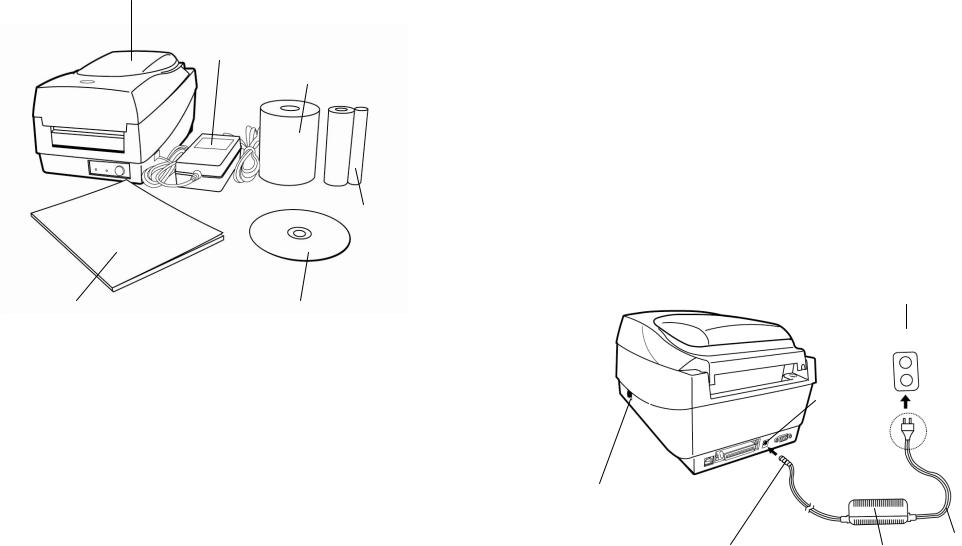
Printer
Power Adapter
Sample Media
Ribbon
User’s Manual |
CD Rom Disk |
Package Contents
•Printer
•Power Adapter
•User’s Manual
•CD Rom Disk
•Ribbon
•Sample Media
2
Connecting the Power Supply
Connect the power supply as below.
WARNING! Do not operate the printer and power supply in an area where they can get wet.
Make sure the power switch is in the "O" position, and be careful not to touch the 36-pin parallel connector.
1.Insert the barrel connector of the Power Adapter into the power jack on the back of the printer. Note the location of the power jack for different models in the diagrams below.
2.Plug the other end of the cord into an AC electrical outlet.
AC Electrical Outlet
Power Jack
Power Switch
Barrel Connector |
Power Adapter Cord |
OS-214 plus
3
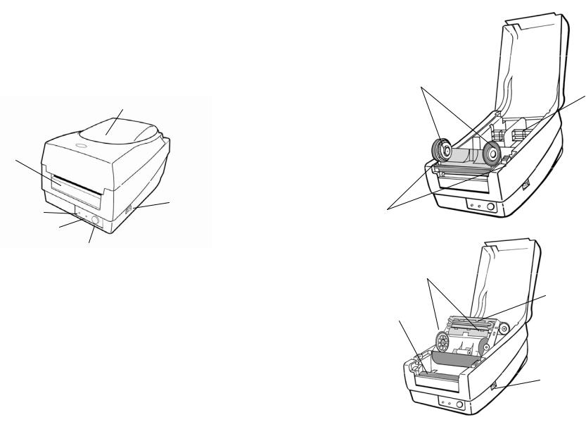
Getting to Know Your Printer
Parts and features of the OS-214 plus are illustrated below.
Parts and Features
Ribbon Pick-up Holder
Media Hanger
Top Cover
H Cover
Power Switch
Power Indicator
Release Levers
Ready Indicator
Feed Button
Ribbon Supply Holder
Thermal Print head
OS-214 plus
Platen Roller
Power Switch
4 |
5 |
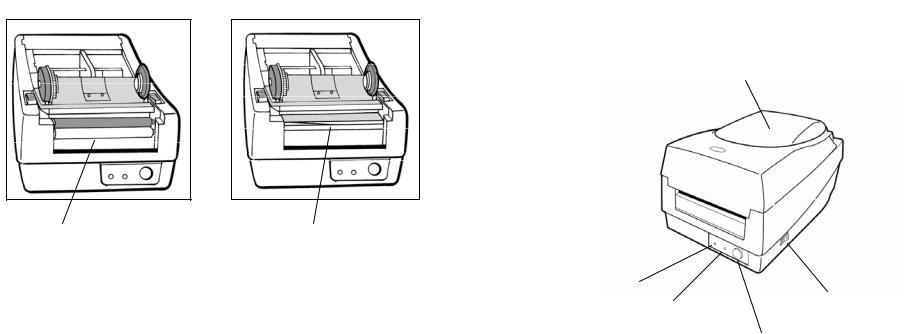
Controls and Indicators
The printer’s controls and indicators are shown in the diagram
Peel-Off Option Cutter Option below. The following table explains control and indicator functions.
Top Cover
White Plastic Roller |
Cutter |
Power Indicator |
|
Ready Indicator |
Power Switch |
Feed Button
6 |
7 |
Control / |
|
Function |
Indicator |
|
|
|
|
|
|
• |
On: power on |
Power Switch |
• |
Off: shut down |
|
||
|
Note: Turn power off before connecting or |
|
|
|
disconnecting cables |
Power Indicator |
|
• Green light shows the power-on status |
|
• Light off shows the power-off status |
|
|
|
|
|
|
• Blinking light indicates error has occurred |
|
|
|
|
• Green shows printer is ready to operate |
|
Ready Indicator |
• Blinking light indicates printer is paused or |
|
|
data transferring |
|
|
|
|
|
• Light off indicates pack flash is under |
|
|
|
processing |
|
|
|
|
• Press to advance labels to the first printing |
|
|
|
position |
Feed Button |
• Press to leave "pause" status |
|
|
|
|
|
• Press to back feed if a label is not properly |
|
|
|
aligned |
|
• Press and hold while turning on the power |
|
|
|
to print out a configuration profile |
|
|
|
8
Loading Ribbon and Media
This section describes how to load ribbon and media into the OS-214 plus printer.
Loading a Ribbon
Note: This section does not apply to direct thermal printing.
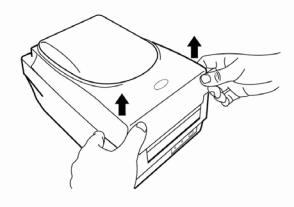
1.Lift the top cover to expose the media compartment.
2.Unlatch the print head module by pushing the two white release levers on the sides toward the rear.
3.Turn over the print head module to expose the ribbon supply holder.
9
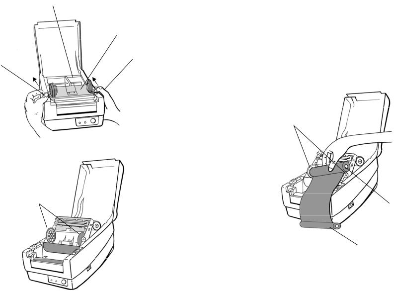
Media Compartment
Print Head Module
Release Lever
Release Lever
Ribbon Supply Holder
10
4.Unwrap the ribbon roll pack and separate the ribbon roll and the bare core.
5.Attach the edge of the ribbon on the bare core and wind it a little bit onto the core.
6.Insert the ribbon roll into the supply holder. (First snap in the left side and then the right side.)
Ribbon Supply Holder
Ribbon Roll
Bare Core
11
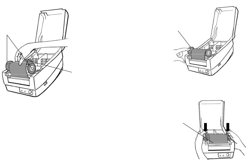
7.Put the print head module down and insert the bare core into the pick-up holder. (First snap in the left side, and then the right side.)
Ribbon Pick-up Holder
Bare Core
12
8.Turn the wheel of the print head module to ensure the ribbon is tightly wound.
9.Press down the print head module firmly until you hear a snap.
Wheel
Print Head Module
13
Loading Media
The OS-214 plus offers three different loading modes: standard, peel-off, or cutting.
•Standard mode allows you to collect each label freely.
•Peel-off mode peels backing material away from the label as it prints. After a label is removed, the next label prints.
•Cutting mode automatically cuts the label after it prints.
Standard Mode
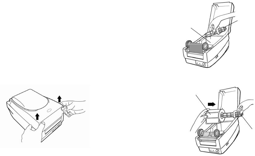
1. Lift the top cover to expose the media compartment.
14
2. Remove the media hanger.
Media Compartment |
Media Hanger |
3. Load the media roll onto the hanger from left to right.
Media Roll
Media Hanger
15

4.Click the media hanger back into the media compartment.
5.Align the media roll to the left end.
6.Move the shield from right to left until it leans against the media.
Media Compartment
Media Roll
Shield
16
7.Unlatch the print head module.
8.Hold the print head module upright with one hand to allow the media to pass under it. Lead the media through the media guides with the other hand.
9.Lead the media over the platen roller.
Print Head Module |
Media Guides |
|
17
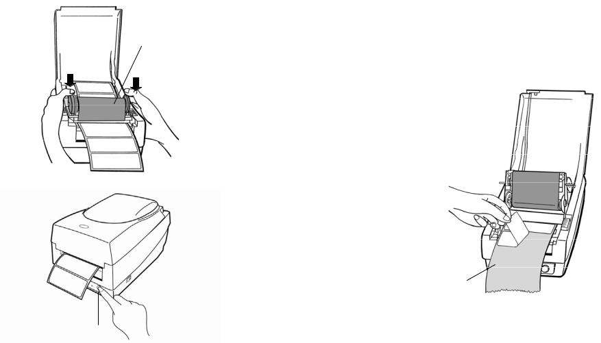
10.Put the print head module down and press down firmly until you hear a snap.
11.Close the top cover and turn on the printer or press the "FEED" button if the printer is already on.
Print Head Module
Feed Button
18
Peel Off Mode
Note: For Peel-off mode you must first install the dispenser kit. Please refer to Appendix I.
Follow Steps 1 to 8 listed in Standard Mode above.
9.Remove enough labels to expose approximately a 6" length of backing paper.
Peeler Sensor 
Backing Paper
19
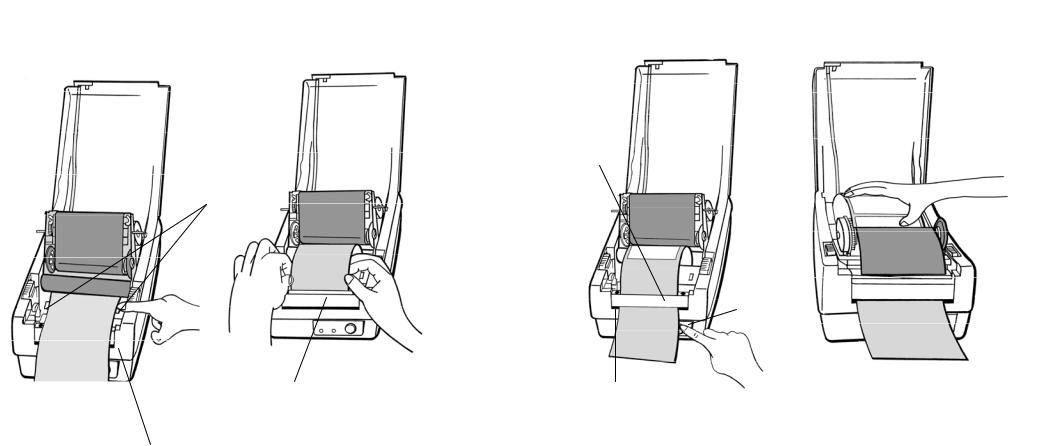
10.Trim the front edge of the label backing paper with scissors or a knife.
11.Lead the backing paper over the dispenser bar, then thread it back into the slot between the dispenser bar and H cover, ensuring that it is inserted between the white plastic roller and platen roller.
12.Press the "FEED" button for the label backing paper to come out from the slot under the H cover.
13.To remove any slack, rewind the media onto the roll. Press down the print head module firmly.
H Cover
Media Guides
Feed Button
H Cover |
Slot |
Dispenser Bar
14. Close the top cover and turn on the printer or press the "FEED" button if the printer is already on.
20 |
21 |
 Loading...