

Page 1
0
Page 2

1
Page 3

NOTICE:
FCC: This device complies with Part 15 of the FCC Rules,
(1) This device may not cause harmful interface, and
(2) This device must accept any interface received,
including interface that may cause undesirable
operation.
CE: This product conforms to the following standards
EMC:EN55022:2006+A1:2007, class B
EN55024:1998+A1:2001+A2:2003
BSMI: This device is compliant with requirement of BSMI
and granted ID No. R3A078
These limits are designed to provide a reasonable
protection against harmful interface when the equipment is
operated under a commercial environment. This equipment
generates, uses, and can radiate radio frequency energy and,
if not installed and used in accordance with the instruction
manual, may cause harmful interface to radio
communications. Operation of this equipment in a
residential area is likely to cause harmful interface in which
case the user will be required to correct the interface at his
/her own expenses.
Note: All brands and trademarks shall belong to their
respective owner.
Note: Specification is subject to changes without notice.
2
Page 4

Using the ArgoxScan 9500
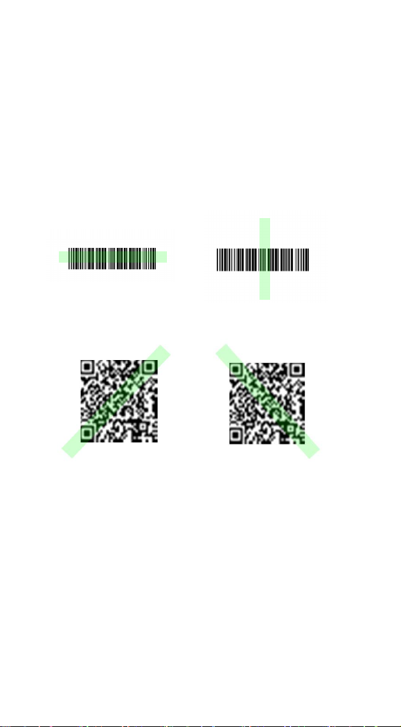
The ArgoxScan automatically scan barcode at a distance.
Simply aim and pull the trigger. Code scanning is performed
along the center of the light bar emitted from the reading
window. This bar must cover the entire code.
Successful scanning shall be obtained by tilting the scanner
with respect to the barcode to avoid direct reflections that
impair the reading performance, especially for 2D barcode.
Recommended Steps
When the required settings have been configured, all settings
are stored in non- volatile memory of scanner after reading
configuration barcodes. Label. Recommended steps are as follows.
1) Set right host interface for your scanner.
2) Set interface to optimize protocol of scanner with your
host in interface section.
3) Set system control of scanner, such as specific
adjustments double confirm, power saving, indicator
and scanning mode which you prefer usage in system
control section.
4) Set code options of scanner for your usage in code
option section. You must make sure to enable the
symbology first, then Min./Max. code length, code ID
checksum and truncate digits are also converted.
5) Set string format of the scanner, such as preamble,
postamble Prefix, suffix, code ID and code name
transmission for your application in string format
section.
Note: If still not work properly. Please contact your dealer for
further information.
3
Page 5

CONTENTS
Introduction ................................................ 8
Default Setting .................................... 9
AS-9500 Specification ...................... 11
Reading Skills of AS-9500 ............... 14
Programming AS-9500 Series Scanner
.......................................................... 15
Interface Selection ............................ 16
RS-232 .............................................. 17
USB HID .......................................... 21
USB Virtual COM ............................ 21
Pin Assignments ............................... 22
System Control ......................................... 28
Scan .................................................. 28
Indication .......................................... 33
Thermal and Centering ..................... 41
Decode Search Mode ........................ 44
Output Sequence ............................... 45
Print Contrast .................................... 51
Video Reverse ................................... 51
Working Orientation ......................... 52
Code Option .............................................. 53
Codabar ............................................. 54
Code 39 ............................................. 56
Code 32 ............................................. 59
4
Page 6

Interleaved 2 of 5 .............................. 60
Code 93 ............................................. 61
Straight 2 of 5 Industrial ................... 62
Straight 2 of 5 IATA ......................... 63
Matrix 2 of 5 ..................................... 64
Code 11 ............................................. 65
Code 128 ........................................... 67
Telepen ............................................. 69
UPC-A .............................................. 71
UPC-E0 ............................................. 74
EAN/JAN-13 .................................... 77
EAN/JAN-8 ...................................... 79
MSI ................................................... 81
Plessey Code ..................................... 83
GS1 DataBar Omnidirectional .......... 84
GS1 DataBar Limited ....................... 84
GS1 DataBar Expanded .................... 85
PosiCode ........................................... 86
Codablock F ...................................... 87
Code 16K .......................................... 88
Code 49 ............................................. 89
PDF417 ............................................. 90
MicroPDF417 ................................... 91
EAN•UCC Composite Codes ........... 92
Postal Codes ..................................... 94
5
Page 7

QR Code ........................................... 98
Data Matrix ....................................... 99
MaxiCode ....................................... 100
Aztec Code ..................................... 101
Chinese Sensible (Han Xin) Code .. 102
String Format .......................................... 103
Prefix/Suffix ................................... 103
Data Formatting .............................. 109
Data Format Editor Commands ...... 112
Imaging Commands ........................ 116
OCR Programming ......................... 125
OCR Templates .............................. 129
Utilities ........................................... 143
Test Chart ........................................ 145
Interface ID ..................................... 150
Product Code ID ............................. 151
ASCII Code Table ........................... 153
OCR Programming Chart ............... 155
How to read Cyrillic-Russian code
operation steps ................................ 156
Program Chart ................................. 157
6
Page 8

7
Page 9

Introduction
Installation
RS-232
1) Disconnect power to the terminal/computer.
2) Connect the external power supply (DC adapter) to the serial
interface cable of the scanner.
3) Plug the serial connector into the serial port on the back
of your computer/terminal. Tighten the two screws to secure
the connector to the port.
4) Plug the power pack into power source.
5) Once the scanner has been fully connected, turn the
terminal / computer power back on.
USB (HID)
1) Connect the USB cable between scanner and PC.
2) Windows will automatically detect the USB device.
USB (Virtual-COM)
1) Install driver, USB Virtual COM Driver, from CD-ROM,
The driver will use the next available COM port
number
2) Connect the USB cable between scanner and PC.
3) Windows will automatically detect the USB device.
Note: If any of the above operation is incorrect, turn off the
power immediately and check any improper
connections. Go through all above steps again
.
8
Page 10

Default Setting
Code Type
Read
Enable
Checksum
Verification
Enable
Checksum
Transmission
Enable
Code
ID
UPC-A V V V c
UPC-E0 V V
V
E
UPC-E1 E
EAN-13 V V V d
EAN-8 V V
V
D
Code-32 <
Code-39 V b
TCIF Linked
Code 39
T
Code-49 I
Interleaved
2 of 5
V
e
Industrial
2 of 5
- -
e
Straight 2 of 5
IATA
f
Straight 2 of 5
Industrial
f
Matrix 2 of 5
m
Codabar V a
Code-128 V j
Code-93 V i
Code-11
V two digits
h
Telepen t
MSI g
Plessey n
For each barcode shown as below:
V = Enabled as default setting
- = Not supported
Empty space = Not enabled at default setting
9
Page 11

GS1 DataBar
Omnidirectional
V - -
y
GS1 DataBar
Limited
V - -
y
GS1 DataBar
Expanded
V - -
y
PosiCode A&B
V
W
Codablock F q
Code 16K o
Code 49 V I
PDF 417 V r
MicroPDF 417
V
R
EAN UCC
Composite
y
Postnet P
Planet Code L
British Post B
Canadia Post
C
Kix Post
(Netherlands)
K
Australian Post
A
Japanese Post
J
China Post Q
Korea Post ?
QR Code V O
Data Matrix V w
MaxiCode V x
Aztec Code V z
Aztec Runes z
10
Page 12
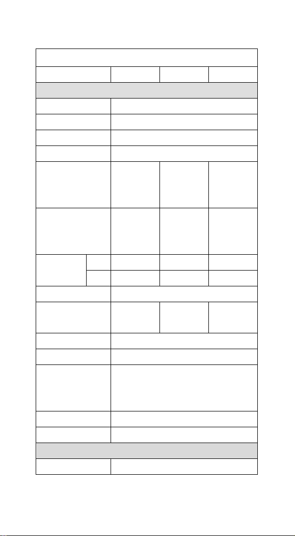
AS-9500 Specification
ArgoScan 9500 series
Specification
AS-9500g
AS-9500HD
AS-9500L
Operational
Light Source
626 nm ± 30 nm Visible Red LED
Aiming Source
526 nm ± 30 nm Visible Green LED
Optical System
752 x 480 CMOS sensor
Motion Tolerance
4 inches / sec
Depth of Scan Field
(PCS=90%,10 mils,
1D : Code 39)
37~175 mm
33~102mm
67~176mm
Depth of Scan Field
(PCS=90%,10 mils,
2D : QR Code)
62~137 mm
34~101mm
85~168mm
Resolution
1D
5mil
4mil
6.6mil
2D
8.3mil
6.7mil
15mil
Print Contrast
25% or more
Focal Point
(from lens plate)
114 mm
114mm
114mm
Scanning Angle
Pitch: ± 40° Skew: ±40°
Rotational Sensitivity
360˚
Decode Capability
Auto-discriminates all standard barcodes;
Other symbologies can be ordered
optionally
Beeper Operation
Volume x 3 and Frequency x 3 or no beep
Indicator
Blue led, vibrator, and adjustable beeper
Mechanical
Length
165.1 mm
11
Page 13
12
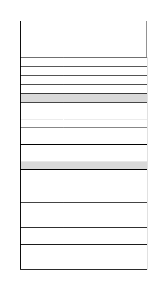
Weight
146 g
Cable
Straight 2.0 m
Connector type
RJ-45 phone jack connector
Case material
ABS and Rubber
Electrical
Input Voltage
3.7 ~ 5.5 VDC
Power
RS232
USB HID
Operating
Max 350mA @ 5V
Standby
Max 65mA@ 5V
Max 60mA@ 5V
Low Power Mode
Max 40mA@5V
*
Agency listing
EMI: FCC, CE, BSMI
Safety: UL, BSMI, CB
Environmental
Operating
Temperature
0℃ to 50℃
(32℉ to 122℉)
Storage Temperature
-20℃ to 60℃
(-4℉ to 140℉)
Humidity
Up to 95% relative humidity,
non-condensing @ 50℃
Light Level
Dark to 100,000 Lux.
Shock
24 drops from 1.8 m to concrete
Resistance
IP 42
Contaminants
Seals to resist airborne particulate
contaminants
Ventilation
None required
Width-handle
32 mm
Width-head
72.8 mm
Depth-handle
54.7 mm
Depth-head
82.5 mm
Page 14
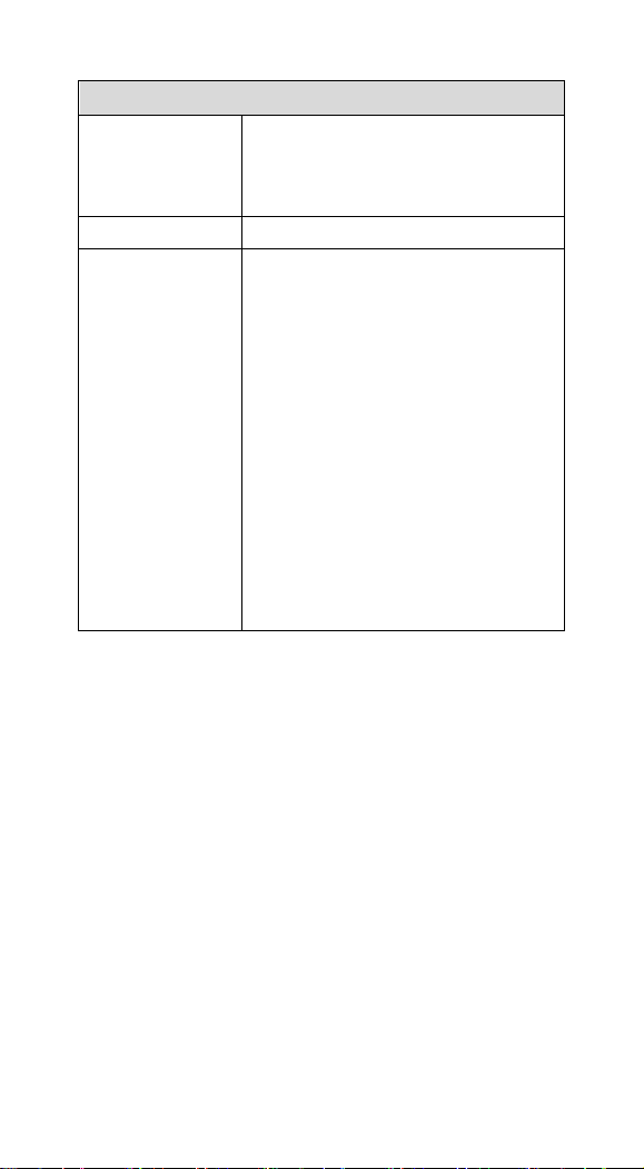
Programming
Programming
method
1. Executing DOS Command by RS-232 or
USB Virtual COM.
2. A scanner reads the programming codes.
Program upgrade
Enabled built-in flash memory
Programmable
characteristics
Code type selection, check digit selection
Decoding option Decoding option
Transmitted character delay, Header
selection, trailer selection, message suffix,
good read beep tone and volume, scanner
trigger selection
Keyboard emulation type (intermessage
delay, keyboard type and keyboard
language)
Serial interface type (ACK/NAK,
Xon/Xoff, RTS/CTS, good read LED
control, start/stop bits)
13
Page 15
Reading Skills of AS-9500
2D Symbol
The engine has a view finder that projects a bright red or
green aiming beam that corresponds to the engine’s
horizontal field of view. The aiming beam should be centered
over the bar code, but it can be positioned in any direction for
a good read.
Linear bar code
The aiming beam is smaller when the engine is closer to the
code and larger when it is farther from the code. Symbologies with
smaller bars or elements (mil size) should be read closer to the unit.
Symbologies with larger bars or elements (mil size) should be read
farther from the unit. To read single or multiple symbols Linear
bar code 2D Matrix symbol (on a page or on an object), hold the
engine at an appropriate distance from the target, send a trigger
command, and center the aiming beam on the symbol. If the
code being scanned is highly reflective (e.g., laminated), it may be
necessary to tilt the code +5° to prevent unwanted reflection.
14
Page 16

Programming AS-9500 Series Scanner
To program the AS- 9500, you must scan a series of programming
barcodes in the correct order. Fold out the back cover of this
manual. You will see a table of alphanumeric barcodes, which are
used to program the various options presented.
To program each option, you must:
1. Scan the Program barcodes.
2. Enter the option mode by scanning the option barcodes
3. The necessary alphanumeric inputs are listed. Scan these
alphanumeric entries from the Program Chart. To confirm
above steps, you must scan the Save barcode.
.
15
Page 17

RS-232 Interface
*USB HID (PC)
USB HID (MAC)
USB Virtual COM
Interface Selection
This decoder built-in scanner comes in one model and
supports interfaces such as RS232 serial, USB virtual COM
and USB HID. In most of the cases, simply selecting an
appropriate cable and configure the proper interface by following
interface selection.
Interface selection: You can change factory interface default
(USB HID) for other type interface. By plugging different cables,
setting right interface, then scan the interface barcode, power cycle
the scanner will be changed to another interface. However, you
must make sure which cable you need.
16
Page 18
RS-232
300
600
1200
2400
4800
9600
19200
38400
57600
*115200
Default Setting
Baud Rate 115200 bps
Data Format 8 data bits, no parity bit, 1 stop bit
Baud Rate
17
Page 19

7 Data,1 Stop, Parity Even
7 Data,1 Stop, Parity None
7 Data,1 Stop, Parity Odd
7 Data,2 Stop, Parity Even
7 Data,2 Stop, Parity None
7 Data,2 Stop, Parity Odd
8 Data,1 Stop, Parity Even
*8 Data,1 Stop, Parity None
8 Data,1 Stop, Parity Odd
Data Bits sets the word length at 7 or 8 bits of data per character.
If an application requires only ASCII Hex characters 0 through 7F
decimal (text, digits, and punctuation), select 7 data bits. For
applications which require use of the full ASCII set, select 8 data
bits per character. Default = 8.
Stop Bits sets the stop bits at 1 or 2. Default = 1.
Parity provides a means of checking character bit patterns for
validity. Default = None.
Data Format
18
Page 20

RS-232
RTS/CTS-If the scanner wants to send the barcode data to
host computer, it will issue the RTS signal first, wait for the
CTS signal from the host computer, and then perform the
normal data communication. If there is no replied CTS signal
from the host computer after the timeout (Response Delay)
duration, the scanner halts transmission until it detects another
active CTS signal.
Xon/Xoff- When the host computer is unable to accept data, it
sends a Xoff code to inform the scanner to suspend data
transmission, and Xon to continue.
ACK/NAK- When the ACK/NAK protocol is used, the scanner
waits for an ACK (acknowledge) or (not acknowledge) from the
host computer after data transmission, and will resend in response
to a NAK.
Response Delay
The unit stays awake to receive data until the RS-232
Receiver Time-Out expires. A trigger command resets the
time-out. When an RS-232 receiver is sleeping, a character
may be sent to wake up the receiver and reset the time-out.
A transaction on the CTS line will also wake up the receiver.
The receiver takes 300 milliseconds to completely come up.
Change the RS-232 receiver time-out by scanning the bar code
below, then scanning digits from the inside back cover
of this manual, then scanning Save. The range is 0 to 300
seconds. Default = 0 seconds (no time-out - always on).
19
Page 21

RTS/CTS On
XON/XOFF On
ACK/NAK On
Response Delay
*RTS/CTS Off
*XON/OFF Off
*ACK/NAK Off
Handshaking
20
Page 22

USB HID
USB HID (PC)
USB HID (MAC)
CTS/RTS On
ACK/NAK On
*CTS/RTS Off
*ACK/NAK Off
Scan the following code to program the AS-9500 for USB HID bar
code imagers.
USB Virtual COM
Scan the following code to program the AS-9500 to emulate a
regular RS-232-based COM port. If you are using a PC, you will
need to download a driver from CD-ROM, The driver will use the
next available COM port number
CTS/RTS Emulation & ACK/NAK Mode
USB Virtual COM
21
Page 23
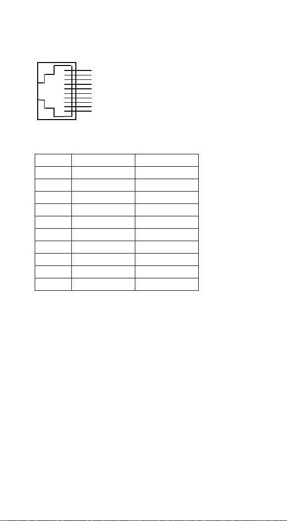
Pin Assignments
Pin
RS-232
USB
1
NC
NC
2
VCC
VCC
3
TXD
TXD 4 NC
NC 5 NC
NC 6 CTS
D+
7
RXD
D-
8
RTS
RTS 9 GND
GND
10
GND
GND
1 2 4
3
5 6 7 8 9
10
10-pin RJ-45 Connector to Scanner Side
22
Page 24
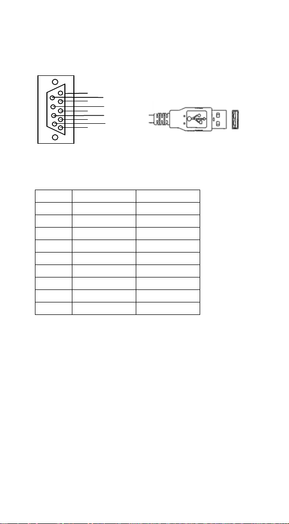
Pin Assignments
Pin
RS-232
USB
1
NC
+5V 2 TXD
D- 3 RXD
D+ 4 NC
GND 5 GND
* 6 NC
* 7 CTS
* 8 RTS
* 9 VCC
*
4 2 3
1
8 6 9 7 5
4
1
Connector to Host Side:
23
Page 25
Keyboard Layout Setting
*United States
B
elgium
Brazil
Canada (French)
Czech Republic
Denmark
Finland (Sweden)
France
Germany/Austria
Greece
Scan the appropriate country code below to program
the keyboard for your country. As a general rule, the
following characters are supported, but need special
care for countries other than the United States:
@ | $ # { } [ ] = / ‘ \ < > ~
24
Page 26

Hungary
Israel (Hebrew)
Italy
Latin America
Netherlands (Dutch)
Norway
Poland
Portugal
Romania
25
Page 27

Keyboard Layout Setting (Continued)
Russia
Slovakia
Sweden
Turkey F
Turkey Q
UK
26
Page 28

SCS
Spain
Switzerland (German)
27
Page 29

System Control
Scan
Scanning output:
You can set the image size to a VGA resolution to accommodate
older applications that require a smaller image size. When Image
VGA is set to On, the resultant image is 640x480 pixels. When
Image VGA is Off, the image is 752x480 pixels.
Scanning mode:
Manual/Serial Trigger Mode
When in manual trigger mode, the imager scans until a bar code is
read, or until the hardware trigger is released.
When in serial mode, the imager scans until a bar code has been
read or until the deactivate command is sent. In serial mode, the
imager can also be set to turn itself off after a specified time has
elapsed (see Read Time-Out, which follows).
Manual Trigger, Low Power (For RS-232 only)
The imager powers down until the trigger is pulled. When the
trigger is pulled, the imager powers up and operates until there is
no triggering for the time set with the Low Power Time-Out bar
code below. There is a delay of up to one second in operation
when the imager is first triggered, but there is no delay when
operating in low power time-out mode.
28
Page 30

Scan
Auto-sense Mode
This programs the imager to work in Auto-sense mode. The LEDs
are either off or at the lowest power for ambient conditions until a
bar code is presented to the imager. Then the LEDs turn on
automatically to read the code. Auto-sense Mode uses ambient
light to detect the bar codes. If the light level in the room is not
high enough, Auto-sense Mode may not work properly.
Snap and Ship
Snap and Ship mode allows you to bypass the decoder and ship an
image directly to the host. In this mode, an image is taken and
shipped upon each trigger pull, instead of being sent to the decoder.
Snap and Ship is useful when you are using your own decoder.
Note: Snap and Ship mode only works if the imager is connected
via an RS-232 serial port or via a USB keyboard. If you use Snap
and Ship when the imager is connected to another interface, it calls
the decoder after each image ship, but only to look for menu
codes.
29
Page 31

Scanning Output
VGA Off
*VGA On
Scanning Mode
*Manual/Serial Trigger
Auto-sense Mode
Manual Trigger, Low Power
Snap and Ship
30
Page 32

Scan
Read Time-Out
Use this selection to set a time-out (in milliseconds) of the
imager’s trigger if the imager is in manual trigger mode. Once the
imager has timed out, you can activate the imager by pressing the
trigger. After scanning the Read Time-Out bar code, set the
time-out duration (from 0-300,000 milliseconds) by scanning
digits from the inside back cover, then scanning Save. Default = 0
(infinite, or no time-out).
Low Power Time-Out Timer
Scan the Low Power Time-Out bar code to change the time-out
duration (in seconds). Then scan the time-out duration (from 0-300
seconds) from the inside back cover, and Save. Default = 120
seconds. If the unit remains idle during the low power time-out
interval, the unit goes into low power mode. Whenever the trigger
is enabled, the low power time-out timer is reset.
Auto-sense LED Behavior after Decode
When an imager is in Auto-sense mode, the LEDs remain on and
continue scanning for a short time after a bar code is decoded. If
you wish to turn the LEDs off immediately after a bar code is
decoded, scan the LEDs Off bar code, below. Default = LEDs On.
Auto-sense LED Time-Out
When using Auto-sense LED Behavior after Decode , you may
want to set the time the LEDs remain off after a decode. To set the
duration of this delay, scan the bar code below, then set the
time-out by scanning digits (0 - 9,999 ms) , then scanning Save.
Once the unit has completed this time-out, it will immediately
resume scanning.
Auto-sense Sensitivity
Auto-sense Sensitivity is a numeric range that increases or
decreases the imager's reaction time to bar code Auto-sense. To set
the sensitivity, scan the Sensitivity bar code, then scan the degree
31
Page 33

of sensitivity (from 0-20) from the inside back cover, and Save. 0
Read Time out
Read Time-Out
Low Power Time-Out
Auto-sense
*LEDs On
LEDs Off
LED Time-Out
LED Time-Out Duration
Hands Free Time-Out
Sensitivity
is the most sensitive setting, and 20 is the least sensitive.
Default = 1.
Hands Free Time-Out
The Auto-sense Modes is referred to as “hands free” modes. If the
hardware trigger is pulled when using a hands free mode, the
imager changes to manual trigger mode. You can set the time the
imager should remain in manual trigger mode by setting the Hands
Free Time-Out. Once the time-out value is reached, (if there have
been no further trigger pulls) the imager reverts to the original
hands free mode. Scan the Hands Free Time-Out bar code, then
scan the time-out duration (from 0-300,000 milliseconds) from the
inside back cover, and Save. Default = 5,000 ms.
32
Page 34

Indication
Beeper
*On
Off
Volume
Low
High
*Medium
Extreme Low
Frequency
Low
*Medium
High
Duration
*Normal Beep
Short Beep
Beeper
The beeper may be programmed On or Off in response to a good
read. Turning this option off, only turns off the beeper response to
a good read indication. All error and menu beeps are still audible.
Volume
The beeper volume codes modify the volume of the beep the
imager emits on a good read.
Frequency
The beeper pitch codes modify the pitch of the beep the imager
emits on a good read.
Duration
The beeper duration codes modify the length of the beep the
imager emits on a good read.
33
Page 35

Vibrator
*On
Off
LED
The LED indicator can not be programmed On or Off in response
to a good read. If user turned off vibrator and beeper, then the LED
indicator will be Off. But when either vibrator or beeper is ON,
then the LED indicator will remain On all the time.
Vibrator
The vibrator provides a unique feature to AS-9500 that user can
understand whether the data is well scanned and sent to Host PC
under an adverse circumstance that the beep sound may not be
heard, or a circumstance requiring extreme quiet that the beep
sounds are not allowed.
34
Page 36

Indication
Illumination Lights
If you want the illumination lights on while reading a bar code,
scan the Lights On bar code, below. However, if you want to turn
just the lights off, scan the Lights Off bar code.
Note: This setting does not affect the aimer light. The aiming light
can be set using Aimer Modes.
Imager Time-Out
Imager Time-Out powers down the imager after the unit has been
idle for the specified time. To prevent the imager from powering
down, set this time-out to 0. Scan the bar code below, then set the
time-out by scanning digits (from 0 -999,999 ms) from the inside
back cover, then scanning Save. Default = 1 ms.
Reread Delay
This sets the time period before the imager can read the same bar
code a second time. Setting a reread delay protects against
accidental rereads of the same barcode. Longer delays are effective
in minimizing accidental rereads at POS (point of sale). Use
shorter delays in applications where repetitive bar code scanning is
required. Reread Delay only works when in Auto-sense Mode
35
Page 37

Illumination Light
*Lights On
Lights Off
Imager Time-Out
Imager Time-Out
Reread Delay
Short (500 ms)
Long (1000 ms)
*Medium (750ms)
Extra Long (2000 ms)
User-Specified Reread Delay
User-Specified Reread Delay
User-Specified Reread Delay
If you want to set your own length for the reread delay, scan the
bar code below, then set the delay (from 0-30,000 milliseconds) by
scanning digits from the inside back cover, then scanning Save.
36
Page 38

Indication
Aimer Delay
The aimer delay allows a delay time for the operator to aim the
imager before the picture is taken. Use these codes to set the time
between when the trigger is activated and when the picture is taken.
During the delay time, the aiming light will appear, but the LEDs
won’t turn on until the delay time is over.
User-Specified Aimer Delay
If you want to set your own length for the duration of the delay,
scan the bar code below, then set the time-out by scanning digits (0
- 4,000 ms) from the back cover of this manual, then scan Save.
Aimer Modes
Interlaced, the illumination and aiming timing is automatically
synchronized to the imager exposure period by the Image Engine.
The engine turns illumination on while the image is being exposed,
and it turns the aiming off at all other times. The interlaced mode
provides the lowest overall current draw and is recommended for
most applications. It also provides the brightest aimer in most
applications. The Image Engine software automatically maintains
an approximate 25% aimer duty cycle, even when the imager
exposure time is at its maximum in dark operating environments.
Concurrent is provided for backwards compatibility with the
4X00 Image Engine series, and is not recommended for most
applications. In concurrent mode, the illumination LEDs are on
continuously, while the aimer LEDs turn off during the imager
exposure period, and on while the imager is not exposing.
Concurrent mode is used to eliminate any flicker of the
illumination LEDs that may be objectionable to the user,
especially when running the engine at 12 MHz. The illumination
LED current is reduced compared to interlaced mode to limit
engine peak current. The image engine software automatically
maintains an approximate 25% aimer duty cycle, even when the
imager exposure time is at its maximum in dark operating
37
Page 39
environments. Concurrent mode provides the brightest appearance
Aimer Delay
200Milliseconds
*Off ( no delay)
400Milliseconds
Delay Duration
Aimer Modes
Concurrent
*Interlaced
of the illumination LEDs of any of the imager operating modes.
This mode may be useful for applications when an operator is
using the illumination LEDs for aiming, such as in fixed mount,
kiosk, or auto trigger applications. Select Off if you don’t want to
use either aimer mode.
Off
38
Page 40

Indication
Number of Beeps
The number of beeps of a good read can be programmed from 1 -
9. The same number of beeps will be applied to the beeper and
LED in response to a good read. For example, if you program this
option to have five beeps, there will be five beeps and five LED
flashes in response to a good read. The beeps and LED flashes are
in sync with one another. To change the number of beeps, scan the
bar code below and then scan a digit (1-9) bar code and the Save
bar code.
Good Read Delay
This sets the minimum amount of time before the imager can read
another bar code. Default = No Delay.
User-Specified Good Read Delay
If you want to set your own length for the good read delay, scan
the bar code below, then set the delay (from 0-30,000 milliseconds)
by scanning digits from the inside back cover, then scanning Save.
39
Page 41

Number of Beep
Number of Pulses
Good Read Delay
*No Delay
Medium Delay (1,000 ms)
Short Delay (500 ms)
Long Delay (1,500 ms)
User-Specified Good Read Delay
User-Specified Good Read Delay
40
Page 42

Thermal and Centering
Thermal Considerations
Care must be taken when designing the Image Engine into any
system. Internal heating of the Image Engine can occur in high
duty cycle scanning applications in several ways. The high
visibility aimer dissipates a significant amount of power as heat.
The illumination and aiming LEDs also release heat, and are a
major contributor to thermal increases in high use or in Auto-sense
mode. An increase in temperature around an Image Engine can
cause noise levels on the imager, degrading image quality. The
thermal rise can also affect the laser diode. In a continuous
scanning or high use environment, the Image Engine temperature
can rise 15° to 20°C. Under high ambient temperature conditions,
the laser diode is at risk of thermal breakdown and possible failure.
The image quality and decode performance will also degrade. The
Power Control PWM can be used to reduce the effect of the
Illumination LEDs on thermal rise, however, this also reduces the
intensity of the illumination. Reducing the intensity of the
illumination reduces total power used but can also reduce the
depth of field in low light environments.
Centering
Use Centering to narrow the imager’s field of view to make sure
the imager reads only those bar codes intended by the user. For
instance, if multiple codes are placed closely together, centering
will insure that only the desired codes are read. (Centering can be
used in conjunction with Aimer Delay, for the most error-free
operation in applications where multiple codes are spaced closely
together. Using the Aimer Delay and Centering features, the
imager can emulate the operation of older systems, such as linear
laser bar code imagers. In the example below, the gray area is the
full imager field of view and the white area is the centering
window. Bar Code 1 will not be read, while Bar Code 2 will be.
41
Page 43

The default centering window is a 128x96 pixel area (640x480
default image size) in the center of the imager’s field of view. The
following diagram illustrates the default top, bottom, left, and right
pixel positions, measured from the top and the left side of the
imager’s field of view.
42
Page 44

Thermal and Centering
Centering On
Top of Centering Window
Left of Centering Window
*Centering Off
Bottom of Centering Window
Right of Centering Window
If a bar code is not within the predefined window, it will not be
decoded or output by the imager. If centering is turned on by
scanning Centering On, the imager only reads codes that intersect
the centering window you specify using the Top, Bottom, Left, or
Right bar codes. Scan Centering On, then scan one of the
following bar codes to change the top, bottom, left, or right of the
centering window. Then scan the percent you want to shift the
centering window using digits on the inside back cover of this
manual. Scan Save. Default Centering = 40% for Top and Left,
60% for Bottom and Right.
43
Page 45

Decode Search Mode
Full Omni-directional
Note: This search mode is the
default setting for the 2D
AS-9500 series Engines.
Quick Omni-directional
Advanced Linear Decoding
Note: This search mode is the
default setting for the
point-and-shoot AS-9500
There are three selectable decode (scanning) modes:
Full Omnidirectional - Searches for bar code features beginning
at the center of an image, and searches to the image’s limits. This
mode reads all symbologies, in any orientation. The Full
Omnidirectional search is very thorough which may slow
performance time.
Quick Omnidirectional - This is an abbreviated search for bar
code features around the center region of an image. This mode
quickly reads all symbologies in any orientation. The Quick
Omnidirectional mode may miss some off-center
symbols, as well as larger Data Matrix and QR Code.
Advanced Linear Decoding - Performs quick horizontal linear
scans in a center band of the image. This mode does quickly read
linear and stacked bar codes. Advanced Linear Decoding cannot
read 2D, OCR, or Postal symbols.
44
Page 46

Output Sequence
Require Output Sequence
When turned off, the bar code data will be output to the host as the
Imager decodes it. When turned on, all output data must conform
to an edited sequence or the Imager will not transmit the output
data to the host device.
Note: This selection is unavailable when the Multiple Symbols
Selection is turned on.
Output Sequence Editor
This programming selection allows you to program the Imager to
output data (when scanning more than one symbol) in whatever
order your application requires, regardless of the order in which
the bar codes are scanned. Reading the Default Sequence symbol
programs the Imager to the Universal values, shown below. These
are the defaults. Be certain you want to delete or clear all formats
before you read the Default Sequence symbol.
Note: To make Output Sequence Editor selections, you’ll need to
know the code I.D., code length, and character matches your
application requires. Use the Alphanumeric symbols (inside back
cover) to read these options.
Note: You must hold the trigger while reading each bar code in the
sequence.
To Add an Output Sequence
1. Scan the Enter Sequence symbol
2. Code I.D.
On the Product Code ID, find the symbology to which you want to
apply the output sequence format. Locate the Hex value for that
symbology and scan the 2 digit hex value from the Programming
Chart (inside back cover).
3. Length
Specify what length (up to 9999 characters) of data output will be
acceptable for this symbology. Scan the four digit data length from
the Programming Chart. (Note: 50 characters is entered as 0050.
9999 is a universal number, indicating all lengths.) When
45
Page 47

calculating the length, you must count any programmed prefixes,
suffixes, or formatted characters as part of the length (unless using
9999).
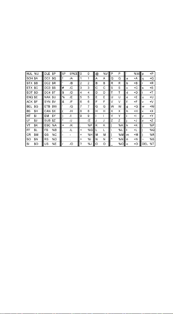
4. Character Match Sequences
On the ASCII Chart , find the Hex value that represents the
character(s) you want to match. Use the Programming Chart to
read the alphanumeric combination that represents the ASCII
characters. (99 is the Universal number, indicating all characters.)
5. End Output Sequence Editor
Scan F F to enter an Output Sequence for an additional
symbology, or Save to save your entries. Other Programming
Selections
•Discard
This exits without saving any Output Sequence changes.
46
Page 48
Output Sequence
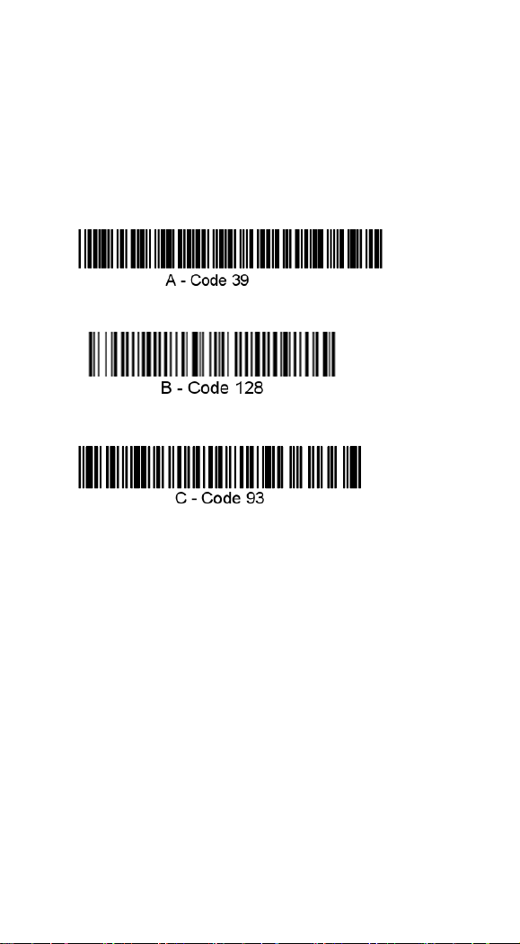
Output Sequence Example
In this example, you are scanning Code 93, Code 128, and Code
39 bar codes, but you want the imager to output Code 39 1st, Code
128 2nd, and Code 93 3rd, as shown below.
Note: Code 93 must be enabled to use this example.
You would set up the sequence editor with the following command
line:
SEQBLK62999941FF6A999942FF69999943FF
The breakdown of the command line is shown below:
SEQBLKsequence editor start command 62 code identifier for
Code 39 9999 code length that must match for Code 39, 9999 = all
lengths 41 start character match for Code 39,
41h = “A” FF termination string for first code
6A code identifier for Code 128 9999 code length that must match
for Code 128,
9999 = all lengths 42 start character match for Code 128,
42h = “B” FF termination string for second code
69 code identifier for Code 93
9999 code length that must match for Code 93,
9999 = all lengths 43 start character match for Code 93,
47
Page 49

43h = “C”
FF termination string for third code To program the previous
example using specific lengths, you would have to count any
programmed prefixes, suffixes, or formatted characters as part of
the length. SEQBLK62001241FF6A001342FF69001243FF
The breakdown of the command line is shown below:
SEQBLK sequence editor start command
62 code identifier for Code 39
0012 A - Code 39 sample length (11) plus CR suffix (1) = 12
41 start character match for Code 39, 41h = “A”
FF termination string for first code
6A code identifier for Code 128
0013 B - Code 128 sample length (12) plus CR suffix (1) = 13
42 start character match for Code 128, 42h = “B”
FF termination string for second code
69 code identifier for Code 93
0012 C - Code 93 sample length (11) plus CR suffix (1) = 12
43 start character match for Code 93, 43h = “C”
FF termination string for third code
48
Page 50

Output Sequence
Output Sequence Editor
Enter Sequence
Default Sequence
Require Output Sequence
Required
On/Not Required
Require Output Sequence
When an output sequence is Required, all output data must
conform to an edited sequence or the imager will not transmit the
output data to the host device. When it’s On/Not Required, the
imager will attempt to get the output data to conform to an edited
sequence, but if it cannot, the imager transmits all output data to
the host device as is. When the output sequence is Off, the bar
code data is output to the host as the imager decodes it.
Note: This selection is unavailable when the Multiple Symbols
Selection is turned on.
*Off
49
Page 51

Multiple Symbols
Note: This feature does not
work when the Imager is in
Low Power mode.
On
*Off
No Read
On
*Off
Multiple Symbols
When this programming selection is turned On, it allows you to
read multiple symbols when the trigger is activated. If you press
and hold the trigger, aiming the Imager at a series of symbols, it
reads unique symbols once, beeping (if turned on) for each read.
The imager attempts to find and decode new symbols as long as
the trigger is activated. When this programming selection is turned
Off, the Imager will only read the symbol closest to the aiming
beam.
No Read
With No Read turned On, the Imager notifies you if a code cannot
be read. If using a Quick*View Scan Data Window, an “NR”
appears when a code cannot be read. If No Read is turned Off, the
“NR” will not appear.
50
Page 52

Print Contrast
Print Contrast
Set Print Contrast
*Default
Video Reverse
On
Print Contrast is used to adjust the way the imager reads Matrix
symbols. If an imager will be seeing consistently heavily printed
matrix symbols, then a Print Contrast of 6 may improve the
reading performance. For consistently light printing, a Print
Contrast of 2 may help. After scanning the Set Print Contrast bar
code, set the Print Contrast (from 1-7) by scanning digits from the
inside back cover, then scanning Save. Default = 4.
Video Reverse
Video Reverse is used to allow the imager to read bar codes that
are inverted. The “Off” bar code below is an example of this type
of bar code. If additional menuing is required, Video Reverse must
be disabled to read the menu bar codes and then re-enabled after
menuing is completed.
Note: Images downloaded from the unit will not be reversed. This
is a setting for decoding only.
51
Page 53

Working Orientation
Working Orientation
*Upright
Upside Down
Rotate Clockwise 90°
Rotate Counterclockwise 90°
Some bar codes are direction-sensitive. For example, Kix codes
and OCR can misread when scanned sideways or upside down.
Use the working orientation settings if your direction-sensitive
codes will not usually be presented upright to the scanner. Default
= Upright.
52
Page 54

Code Option
All Symbologies
All Symbologies On
All Symbologies Off
If you want to decode all the symbologies allowable for your
imager, scan the All Symbologies On code. On the other hand,
you want to decode only a particular symbology, scan All
Symbologies Off followed by the On symbol for that particular
symbology.
Message Length Description
You may set the valid reading length of some of the bar code
symbologies. If the data length of the scanned bar code doesn’t
match the valid reading length, the imager will issue an error beep.
You may set the same value for minimum and maximum length to
force the imager to read fixed length bar code data. This helps
reduce the chances of a misread.
EXAMPLE: Decode only those bar codes with a count of 9-20
characters. Min. length = 09 Max. length = 20
EXAMPLE: Decode only those bar codes with a count of 15
characters. Min. length = 15 Max. length = 15. For a value other
than the minimum and maximum message length defaults, scan the
bar codes included in the explanation of the symbology, then scan
the digit value of the message length and Save bar codes. The
minimum and maximum lengths and the defaults are included with
the respective symbologies
Start/Stop Characters
Start/Stop characters identify the leading and trailing ends of
the bar code.
53
Page 55

Codabar
<Default All Codabar Settings>
*On
Off
Start /Stop Character
Transmit
*Don’t Transmit
Check Character
*No Check Character
Validate and Transmit
Validate Modulo 16 and
Transmit
Validate Modulo 16 ,but Don’t
Transmit
Check Character
Codabar check characters are created using different “modulos.”
You can program the imager to read only Codabar bar codes with
Modulo 16 check characters. No Check Character indicates that
the imager reads and transmits bar code data with or without a
check character. When Check Character is set to Validate and
Transmit, the imager will only read Codabar bar codes printed
with a check character, and will transmit this character at the end
of the scanned data. When Check Character is set to Validate, but
Don’t Transmit, the unit will only read Codabar bar codes printed
with a check character, but will not transmit the check character
with the scanned data.
54
Page 56

Codabar
Message Length
*On
Require
Maximum Message Length
Off
Minimum Message Length
Concatenation
Codabar supports symbol concatenation. When you enable
concatenation, the imager looks for a Codabar symbol having a
“D” start character, adjacent to a symbol having a “D” stop
character. In this case the two messages are concatenated into one
with the “D” characters omitted. Default = On.
Select Require to prevent the imager from decoding a single
“D” Codabar symbol without its companion. This selection
has no effect on Codabar symbols without Stop/Start D
characters.
Message Length
Scan the bar codes below to change the message length. Minimum
and Maximum lengths = 2-60. Minimum Default = 4, Maximum
Default = 60.
55
Page 57

Code 39
*On
Transmit
*No Check Character
Validate and Transmit
Off
*Don’t Transmit
Validate, but Don’t Transmit
Start/Stop Characters
Start/Stop characters identify the leading and trailing ends of
the bar code. Youmay either transmit, or not transmit
Start/Stop characters. Default = Don’t Transmit.
Check Character
No Check Character indicates that the imager reads and
transmits bar code data with or without a check character
When Check Character is set to Validate, but Don’t Transmit,
the unit only reads Code 39 bar codes printed with a check
character, but will not transmit the check character with the
scanned data. When Check Character is set to Validate and
Transmit, the imager only reads Code 39 bar codes printed
with a check character, and will transmit this character at the
end of the scanned data. Default = No Check Character.
<Default All Code 39 Settings>
56
Page 58

Code 39
Code 39
Minimum Message Length
Append On
Maximum Message Length
*Append Off
Message Length
Scan the bar codes below to change the message length.. Minimum
and Maximum lengths = 0-48. Minimum Default = 0, Maximum
Default = 48.
Append
This function allows the imager to append the data from several
Code 39 bar codes together before transmitting them to the host
computer. When this function is enabled, the imager stores those
Code 39 bar codes that start with a space (excluding the start and
stop symbols), and does not immediately transmit the data. The
imager stores the data in the order in which the bar codes are read,
deleting the first space from each. The imager transmits the
appended data when it reads a Code 39 bar code that starts with a
character other than a space.
57
Page 59
Full ASCII
If Full ASCII Code 39 decoding is enabled, certain character
pairs within the bar code symbol will be interpreted as a single
character. For example: $V will be decoded as the ASCII character
SYN, and /C will be decoded as the ASCII character #.
Character pairs /M and /N decode as a minus sign and period
respectively. Character pairs /P through /Y decode as 0 through 9.
58
Page 60

Code 39
Full ASCII On
Code 39 Code Page
*Full ASCII Off
Code 32
On
*Off
Code Page
Code pages define the mapping of character codes to
characters. If the data received does not display with the proper
characters, it may be because the barcode being scanned was
created using a code page that is different from the one the host
program is expecting. If this is the case, scan the bar code below,
select the code page with which the bar codes were created and
scan the value and the Save bar code. The data characters should
then appear properly.
Code 32
Code 32 Pharmaceutical is a form of the Code 39 symbology
used by Italian pharmacies. This symbology is also known as
PARAF.
Note: Trioptic Code must be turned off while scanning Code 32
Pharmaceutical codes.
59
Page 61

Interleaved 2 of 5
*On
*No Check Digit
Validate and Transmit
Maximum Message Length
Off
Validate , but Don’t Transmit
Minimum Message Length
Check Digit
No Check Digit indicates that the imager reads and transmits bar
code data with or without a check digit.
When Check Digit is set to Validate, but Don’t Transmit,
the unit only reads Interleaved 2 of 5 bar codes printed with
a check digit, but will not transmit the check digit with the
scanned data.
When Check Digit is set to Validate and Transmit, the imager
only reads Interleaved 2 of 5 bar codes printed with a check digit,
and will transmit this digit at the end of the scanned data.
Message Length
Scan the bar codes below to change the message length. Minimum
and Maximum lengths = 2-80. Minimum Default = 4, Maximum
Default = 80.
<Default All Interleaved 2 of 5 Settings>
60
Page 62

Code 93
*On
Minimum Message Length
Code 93 Code Page
Off
Maximum Message Length
Code 93 Message Length
Scan the bar codes below to change the message length. Minimum
and Maximum lengths = 0-80. Minimum Default = 0, Maximum
Default = 80.
Code Page
Code pages define the mapping of character codes to characters. If
the data received does not display with the proper characters, it
may be because the barcode being scanned was created using a
code page that is different from the one the host program is
expecting. If this is the case, scan the bar code below, select the
code page with which the bar codes were created and scan the
value and the Save bar code from the Programming Chart on the
inside the back cover of this manual. The data characters should
then appear properly.
<Default All Code 93 Settings>
61
Page 63
Straight 2 of 5 Industrial
On
Minimum Message Length
*Off
Maximum Message Length
Message Length
Scan the bar codes below to change the message length. Minimum
and Maximum lengths = 1-48. Minimum Default = 4, Maximum
Default = 48.
<Default All Straight 2 of 5 Industrial Settings>
62
Page 64

Straight 2 of 5 IATA
On
Maximum Message Length
*Off
Minimum Message Length
Message Length
Scan the bar codes below to change the message length. Minimum
and Maximum lengths = 1-48. Minimum Default = 4, Maximum
Default = 48
<Default All Straight 2 of 5 IATA Settings>
.
63
Page 65

Matrix 2 of 5
On
Minimum Message Length
*Off
Maximum Message Length
Message Length
Scan the bar codes below to change the message length. Minimum
and Maximum lengths = 1-80. Minimum Default = 4, Maximum
Default = 80.
<Default All Matrix 2 of 5 Settings>
64
Page 66
Code 11
On
One Check Digit
Minimum Message Length
*Off
*Two Check Digits
Maximum Message Length
Check Digits Required
This option sets whether 1 or 2 check digits are required with Code
11 bar codes. Default = Two Check Digits.
Message Length
Scan the bar codes below to change the message length. Minimum
and Maximum lengths = 1-80. Minimum Default = 4, Maximum
Default = 80.
<Default All Code 11 Settings>
65
Page 67

66
Page 68

Code 128
ISBT 128 Concatenation
The use of ISBT formats requires a paid license. The ISBT 128
Application Specification describes 1) the critical data elements
for labeling blood products, 2) the current recommendation to use
Code 128 due to its high degree of security and its
space-efficient design, 3) a variation of Code 128 that supports
concatenation of neighboring symbols, and 4) the standard layout
for bar codes on a blood product label. Use the bar codes below to
turn concatenation on or off. Default = Off.
Message Length
Scan the bar codes below to change the message length. Minimum
and Maximum lengths = 0-80. Minimum Default = 0, Maximum
Default = 80.
Code Page
Code pages define the mapping of character codes to characters. If
the data received does not display with the proper characters, it
may be because the bar code being scanned was created using a
code page that is different from the one the host program is
expecting. If this is the case, scan the bar code below, select the
code page with which the bar codes were created, and scan the
value and the Save The data characters should then appear
properly. Default = 2.
67
Page 69

*On
ISBT 128 On
Minimum Message Length
Off
* ISBT 128 Off
Maximum Message Length
Code Page
Code 128 Code Page
<Default All Code 128 Settings>
68
Page 70

Telepen
On
*AIM Telepen Output
Minimum Message Length
*Off
Original Telepen Output
Maximum Message Length
Telepen Output
Using AIM Telepen Output, the imager reads symbols with
start/stop pattern 1 and decodes them as standard full ASCII
(start/stop pattern 1). When Original Telepen Output is selected,
the imager reads symbols with start/stop pattern 1 and decodes
them as compressed numeric with optional full ASCII (start/stop
pattern 2). Default = AIM Telepen Output.
Message Length
Scan the bar codes below to change the message length. Minimum
and Maximum lengths = 1-60. Minimum Default = 1, Maximum
Default = 60.
<Default All Telepen Settings>
69
Page 71

70 71
Page 72

UPC-A
*On
Off
Check Digit
*On
Off
Number System
*On
Off
Check Digit
This selection allows you to specify whether the check digit should
be transmitted at the end of the scanned data or not. Default = On.
Number System
The numeric system digit of a U.P.C. symbol is normally
transmitted at the beginning of the scanned data, but the unit can
be programmed so it will not transmit it. Default = On.
<Default All UPC-A Settings>
Page 73

UPC-A
Addenda
This selection adds 2 or 5 digits to the end of all scanned UPC-A
data.Default = Off for both 2 Digit and 5 Digit Addenda.
Addenda Required
When Required is scanned, the imager will only read UPC-A bar
codes that have addenda. You must then turn on a 2 or 5 digit
addenda. Default = Not Required.
Addenda Separator
When this feature is on, there is a space between the data from the
bar code and the data from the addenda. When turned off, there is
no space. Default = On.
UPC-A/EAN-13 with Extended Coupon Code
Use the following codes to enable or disable UPC-A and EAN-13
with Extended Coupon Code. Default = On.
72
Page 74

Addenda
2 Digit Addenda On
5 Digit Addenda On
*2 Digit Addenda Off
*5 Digit Addenda Off
Addenda Required
Required
*Not Required
Addenda Separator
*On
Off
UPC-A/EAN-13 with Extended
Coupon Code
*On
Off
73
Page 75

UPC-E0
Most U.P.C. bar codes lead with the 0 number system. For these
codes, use the UPC-E0 selection. If you need to read codes that
lead with the 1 number system. Default = On.
UPC-E0 Expand
UPC-E Expand expands the UPC-E code to the 12 digit, UPC-A
format. Default = Off.
Addenda Required
When Addenda Required is set to on, the imager will only read
UPC-E bar codes that have addenda.
Addenda Separator
When this feature is on, there is a space between the data from the
bar code and the data from the addenda. When turned off, there is
no space.
Check Digit
Check Digit specifies whether the check digit should be
transmitted at the end of the scanned data or not. Default = On.
Number System
The numeric system digit of a U.P.C. symbol is normally
transmitted at the beginning of the scanned data, but the unit can
be programmed so it will not transmit it. Default = On.
74
Page 76

*UPC-E0 On
UPC-E0 Off
UPC-E0 Expand
On
*Off
Addenda Required
Required
*Not Required
Addenda Separator
*On
Off
Check Digit
*On
Off
Number System
*On
Off
<Default All UPC-E Settings>
75
Page 77

UPC-E0
Addenda
2 Digit Addenda On
5 Digit Addenda On
*2 Digit Addenda Off
*5 Digit Addenda Off
UPC-E1
UPC-E1 On
*UPC-E1 Off
Addenda
This selection adds 2 or 5 digits to the end of all scanned UPC-E
data. Default = Off for both 2 Digit and 5 Digit Addenda
UPC-E1
Most U.P.C. bar codes lead with the 0 number system. For these
codes. If you need to read codes that lead with the 1 number
system, use the UPC-E1 selection. Default = Off
76
Page 78

EAN/JAN-13
*On
Off
Check Digit
*On
Off
ISBN Translate
On
*Off
Check Digit
This selection allows you to specify whether the check digit should
be transmitted at the end of the scanned data or not.
ISBN Translate
This selection causes EAN-13 Bookland symbols to be translated
into their equivalent ISBN number format.
<Default All EAN/JAN Settings>
77
Page 79

EAN/JAN-13
Addenda
2 Digit Addenda On
5 Digit Addenda On
*2 Digit Addenda Off
*5 Digit Addenda Off
Addenda Required
Required
*No Required
Addenda Separator
*On
Off
Addenda
This selection adds 2 or 5 digits to the end of all scanned
EAN/JAN-13 data.
Addenda Required
When Addenda required is set to on, the imager will only read
EAN/JAN-13 bar codes that have addenda.
Addenda Separator
When this feature is on, there is a space between the data from the
bar code and the data from the addenda. When turned off, there is
no space.
78
Page 80

EAN/JAN-8
*On
Off
Check Digit
*On
Off
Addenda
2 Digit Addenda On
5 Digit Addenda On
*2 Digit Addenda Off
*5 Digit Addenda Off
Check Digit
This selection allows you to specify whether the check digit should
be transmitted at the end of the scanned data or not. Default = On.
Addenda
This selection adds 2 or 5 digits to the end of all scanned
EAN/JAN-8 data. Default = Off for both 2 Digit and 5 Digit
Addenda.
<Default All EAN/JAN-8 Settings>
79
Page 81

EAN/JAN-8
Addenda Required
Required
*Not Required
Addenda Separator
*On
Off
Addenda Required
When Addenda Required is set to on, the imager will only read
EAN/JAN-8 bar codes that have addenda.
EAN/JAN-8 Addenda Separator
When this feature is on, there is a space between the data from the
bar code and the data from the addenda. When turned off, there is
no space.
80
Page 82

MSI
On
*Validate Type 10, but Don’t
Transmit
Minimum Message Length
*Off
Validate Type 10 and Transmit
Maximum Message Length
MSI Check Character
Different types of check characters are used with MSI bar codes.
You can program the imager to read MSI bar codes with Type 10
check characters.
When Check Character is set to Validate and Transmit, the
imager will only read MSI bar codes printed with the specified
type check character, and will transmit this character at the end of
the scanned data. When Check Character is set to Validate, but
Don’t Transmit, the unit will only read MSI bar codes printed
with the specified type check character, but will not transmit the
check character with the scanned data.
Message Length
Scan the bar codes below to change the message length. Minimum
and Maximum lengths = 4-48. Minimum Default = 4, Maximum
Default = 48.
<Default All MSI Settings>
81
Page 83

82 83
Page 84

Plessey Code
On
Minimum Message Length
*Off
Maximum Message Length
Message Length
Scan the bar codes below to change the message length. Minimum
and Maximum lengths = 4-48. Minimum Default = 4, Maximum
Default = 48.
<Default All Plessey Code Settings>
Page 85

GS1 DataBar Omnidirectional
*On
Off
*On
Off
<Default All GS1 DataBar Omnidirectional Settings>
GS1 DataBar Limited
<Default All GS1 DataBar Limited Settings>
84
Page 86

GS1 DataBar Expanded
*On
Minimum Message Length
Off
Maximum Message Length
Message Length
Scan the bar codes below to change the message length. Minimum
and Maximum lengths = 4-74. Minimum Default = 4, Maximum
Default = 74.
<Default All GS1 DataBar Expanded Settings>
85
Page 87

PosiCode
* On
A and B On ( No Limited )
*A and B and Limited B On
( Limited A Off )
Off
A and B and Limited On
( Limited B Off )
Message Length
Minimum Message Length
Maximum Message Length
Trioptic Code
You have to have PosiCode A and B on to read any of the
PosiCode symbologies.
Message Length
Scan the bar codes below to change the message length. Minimum
and Maximum lengths = 2-80. Minimum Default = 4, Maximum
Default = 48.
Trioptic Code
Note: If you are going to scan Code 32 Pharmaceutical codes,
Trioptic Code must be off. Trioptic Code is used for labeling
magnetic storage media
<Default All PosiCode Settings>
86
Page 88

On
*Off
Codablock F
On
Minimum Message Length
*Off
Maximum Message Length
Message Length
Scan the bar codes below to change the message length. Minimum
and Maximum lengths = 1-2048. Minimum Default = 1, Maximum
Default = 2048
<Default All Codablock F Settings>
.
87
Page 89

Code 16K
On
Minimum Message Length
*Off
Maximum Message Length
Message Length
Scan the bar codes below to change the message length. Minimum
and Maximum lengths = 0-160. Minimum Default = 1, Maximum
Default = 160.
<Default All Code 16K Settings>
88
Page 90

Code 49
*On
Minimum Message Length
Off
Maximum Message Length
Message Length
Scan the bar codes below to change the message length. Minimum
and Maximum lengths = 1-81. Minimum Default = 1, Maximum
Default = 81.
<Default All Code 49 Settings>
89
Page 91

PDF417
*On
Minimum Message Length
Off
Maximum Message Length
Message Length
Scan the bar codes below to change the message length. Minimum
and Maximum lengths = 1-2750. Minimum Default = 1, Maximum
Default = 2750.
<Default All PDF417 Settings>
90
Page 92

MicroPDF417
* On
Minimum Message Length
Off
Maximum Message Length
Message Length
Scan the bar codes below to change the message length. Minimum
and Maximum lengths = 1-366. Minimum Default = 1, Maximum
Default = 366.
<Default All Micro PDF417 Settings>
91
Page 93

EAN•UCC Composite Codes
Linear codes are combined with a unique 2D composite
component to form a new class called EAN•UCC Composite
symbology. EAN•UCC Composite symbologies allow for the
co-existence of symbologies already in use.
UPC/EAN Version
Scan the UPC/EAN Version On bar code to decode EAN•UCC
Composite symbols that have a UPC or EAN linear component.
(This does not affect EAN•UCC Composite symbols with a
UCC/EAN-128 or GS1 DataBar linear component.)
Message Length
Scan the bar codes below to change the message length. Minimum
and Maximum lengths = 1-2435. Minimum Default = 1, Maximum
Default = 2435
Emulation
The imager can automatically format the output from any
EAN•UCC data carrier to emulate what would be encoded in an
equivalent UCC/EAN-128 or GS1 DataBar and Composite symbol.
EAN•UCC data carriers include UPC-A and UPC-E, EAN-13
and EAN-8, ITF-14, UCC/EAN-128, and EAN•UCC GS1 DataBar
and Composites. Data from 2D symbols such as Aztec Code, Data
Matrix, or QR Code, which encode a leading FNC1, also invoke
EAN•UCC emulation. If UCC/EAN-128 Emulation is selected, the
AIM Symbology Identifier is reported as “]C1”. If GS1 DataBar
Emulation is selected, the AIM Symbology Identifier is reported as
“]e0.” Any application that accepts EAN•UCC data can be
simplified since it only needs to recognize one data carrier type.
92
Page 94

EAN•UCC Composite Codes
EAN•UCC Composite Codes
On
*Off
UPC/EAN Version
UPC / EAN Version On
*UPC / EAN Version Off
Message Length
Minimum Message Length
Maximum Message Length
Emulation
GS1 DataBar Emulation
*EAN.UCC Emulation Off
128 Emulation
TCIF Link Code 39
TLC39 On
*TLC39 Off
TCIF Linked Code 39 (TLC39)
This code is a composite code since it has a Code 39 linear
component and a MicroPDF417 stacked code component. All bar
code readers are capable of reading the Code 39 linear component.
The MicroPDF417 component can only be decoded if TLC39 On
is selected. The linear component may be decoded as Code 39
even if TLC39 is off.
93
Page 95

Postal Codes
On
Transmit Check Digit
*Off
*Don’t Transmit Check Digit
On
Transmit Check Digit
*Off
*Don’t Transmit Check Digit
Note: For best performance when reading a postal symbology, all
other postal symbologies should be turned off. The following
postal codes can only be read by a 2D AS-9500 series Engine.
Postnet
Check Digit
This selection allows you to specify whether the check digit should
be transmitted at the end of the scanned data.
Planet Code
Check Digit
This selection allows you to specify whether the check digit should
be transmitted at the end of the scanned data.
94
Page 96

Postal Codes
On
*Off
On
*Off
On
*Off
On
*Off
On
*Off
British Post
Canadian Post
Kix (Netherlands) Post
Note: Kix code can misread when scanned sideways or upside
down.
Australian Post
Japanese Post
95
Page 97

On
Minimum Message Length
*Off
Maximum Message Length
China Post
Message Length
Scan the bar codes below to change the message length. Minimum
and Maximum lengths = 2-80. Minimum Default = 4, Maximum
Default = 80.
<Default All China Post Settings>
96
Page 98

Postal Codes
On
Minimum Message Length
*Off
Maximum Message Length
Korea Post
Message Length
Scan the bar codes below to change the message length. Minimum
and Maximum lengths = 2-80. Minimum Default = 4, Maximum
Default = 48.
<Default All Korea Post Settings>
97
Page 99

QR Code
*On
Minimum Message Length
Off
Maximum Message Length
This selection applies to both QR Code and Micro QR Code.
Message Length
Scan the bar codes below to change the message length. Minimum
and Maximum lengths = 1-3500. Minimum Default = 1, Maximum
Default = 3500.
<Default All QR Code Settings>
98
Page 100

Data Matrix
*On
Minimum Message Length
Off
Maximum Message Length
Message Length
Scan the bar codes below to change the message length. Minimum
and Maximum lengths = 1-1500. Minimum Default = 1, Maximum
Default = 1500.
<Default All Data Matrix Settings>
99
 Loading...