

Page 1
®
Architect
User’s Manual
DOC. NO. UM-PT202-03
Version 1.11
January 2013
Page 2

TABLE OF CONTENTS
Chapter 1: Introduction ...........................................................................1
Features
System Requirements...................................................................................... 2
Installing the Software ..................................................................................... 2
Opening the Software....................................................................................... 6
......................................................................................................................... 1
Chapter 2: Architect® Interface ...................................................................7
Main Menu....................................................................................................... 7
File Menu
Define Menu .......................................................................................8
Setup Menu ........................................................................................9
Build Menu ..........................................................................................9
Tool Menu ........................................................................................ 10
View Menu ....................................................................................... 10
Window Menu .................................................................................. 10
Help Menu........................................................................................ 11
Toolbars .........................................................................................................11
Main Toolbar .....................................................................................11
Node Toolbar .................................................................................................13
Windows ........................................................................................................13
....................................................................................................................7
Chapter 3: Creating a New Project ............................................................14
Step 1: Configure Project Settings
General Page ................................................................................... 14
AID Setup Page ............................................................................... 15
Record Page .................................................................................... 15
Font Tool Page ................................................................................ 15
Barcode Page................................................................................... 15
Bluetooth Page................................................................................. 16
Lookup Page…................................................................................. 16
Step 2: Create Nodes ...................................................................................17
Note Node .........................................................................................17
Display Node..................................................................................... 17
Input Node ........................................................................................ 20
Operand Node .................................................................................. 26
Program Node .................................................................................. 29
Transmit Node................................................................................... 30
Bluetooth Trans................................................................................. 31
Step 3: Create Links...................................................................................... 32
Step 4: Create the Record File...................................................................... 35
Step 5: Compile and Simulate ...................................................................... 38
Compile the Project .......................................................................... 38
Simulate the Application ................................................................... 39
Step 6: Configure the Communication Settings ........................................... 40
Step 7: Download the Application to the Terminal........................................ 41
.......................................................................14
Chapter 4: Sample Project.......................................................................... 42
Page 3

How to Make This Project............................................................................. 43
Page 4

Page 5

1
A
RCHITECT
®
U
SER’S
MANUAL
1
Introduction
Chapter 1: Introduction
Architect® is a Windows-based so
and directly upload appli
Terminals.
simplicity in
It is
Architect® is designed for n
customary methods, basic program
an application. But with Archit
can develop an applicat
program
commands to execute.
Architect® incorporates a sy
design, compile, simulate and download.
Its’
user-friendly interface provides users the
designing a project suitable for their business needs.
similar to drawing objects and lines on a piece of paper
node offers versatility that allows users to define basic
cations for use with PT
ion. For more advanced users, the
ftware program use to create
ovice and advanced users. Unlike
ming is required to develop
ect’s
node functions, novice
stematic project flow: create,
-20
series
Features
•
Reduces operation cost. Th
separate compiler.
•
User-friendly. Architect uses nodes and drag-and-drop
functions to create and define project properties.
•
Systematic flow.
maintained.
•
Uses Basic language. To
demands, Architect® supports
utilizes Basic Interpre
•
Comes with additional tools. Architect® also comes with a
built-in
Simulator and PT FileManager® . For more details,
Projects can be easily understood and
ere is no n
cope with more complex business
Basic programming input
ter to compile applications.
eed to pu
rchase a
.
users
and
Page 6
2
1
A
RCHITECT
®
U
SER’S
MANUAL
Introduction
see
“Simulator
page 41.
on
page 39”
and PT File Manager on
System Requirements
Before you start installing the software, make sure that your
computer meets the following system requirements:
•
IBM Intel 80586 or above
•
Microsoft Windows XP / 2000 / Vista
•
64 MB RAM
•
5 MB
NOTE: Install Basic Interpreter in the Terminal to ensure
co
mpatibility when ru
hard disk space for software installation
nning projects created with Ar
chitect.
Installing the Software
1.
Insert the installation CD in your
the setup file.
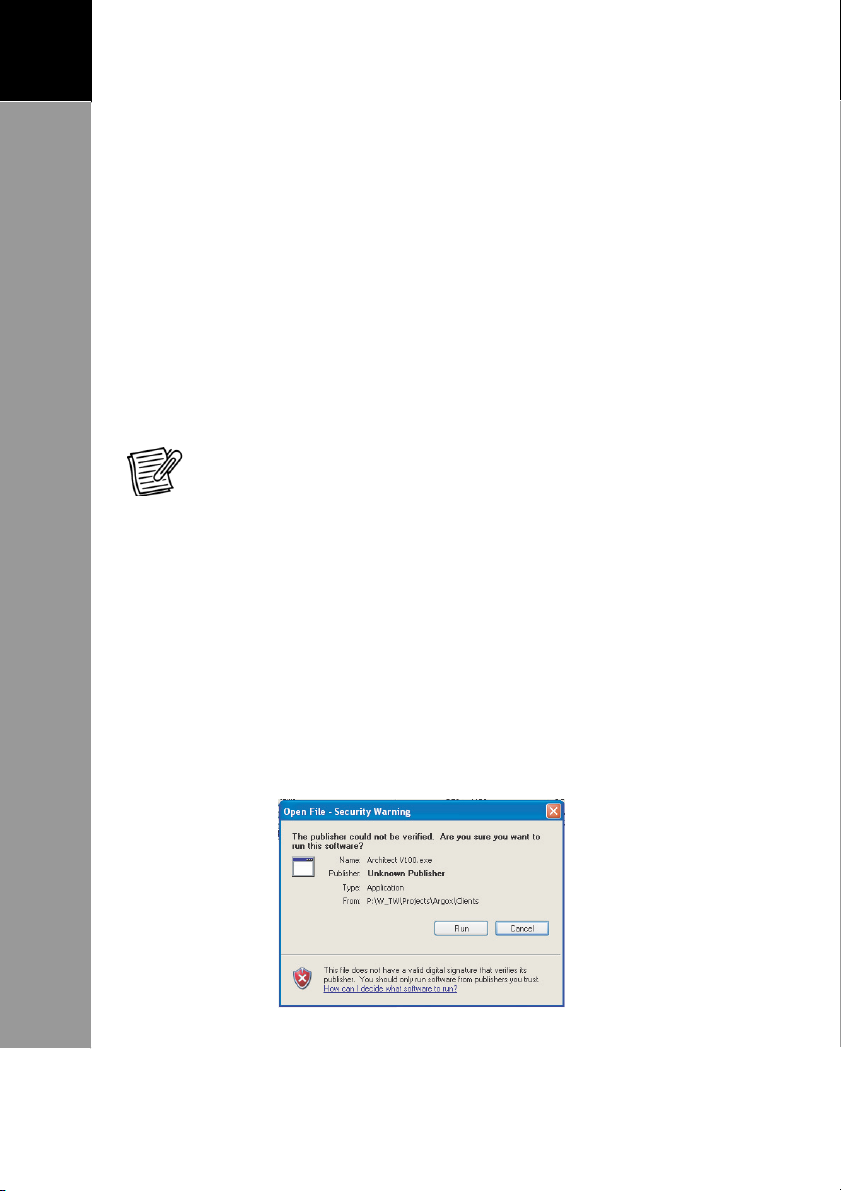
2.
Double-click
below appears.
“Ar
chitect Vxxx.exe”. The window on the
CD-ROM drive and locate
Page 7
3
A
RCHITECT
®
U
SER’S
MANUAL
1
Introduction
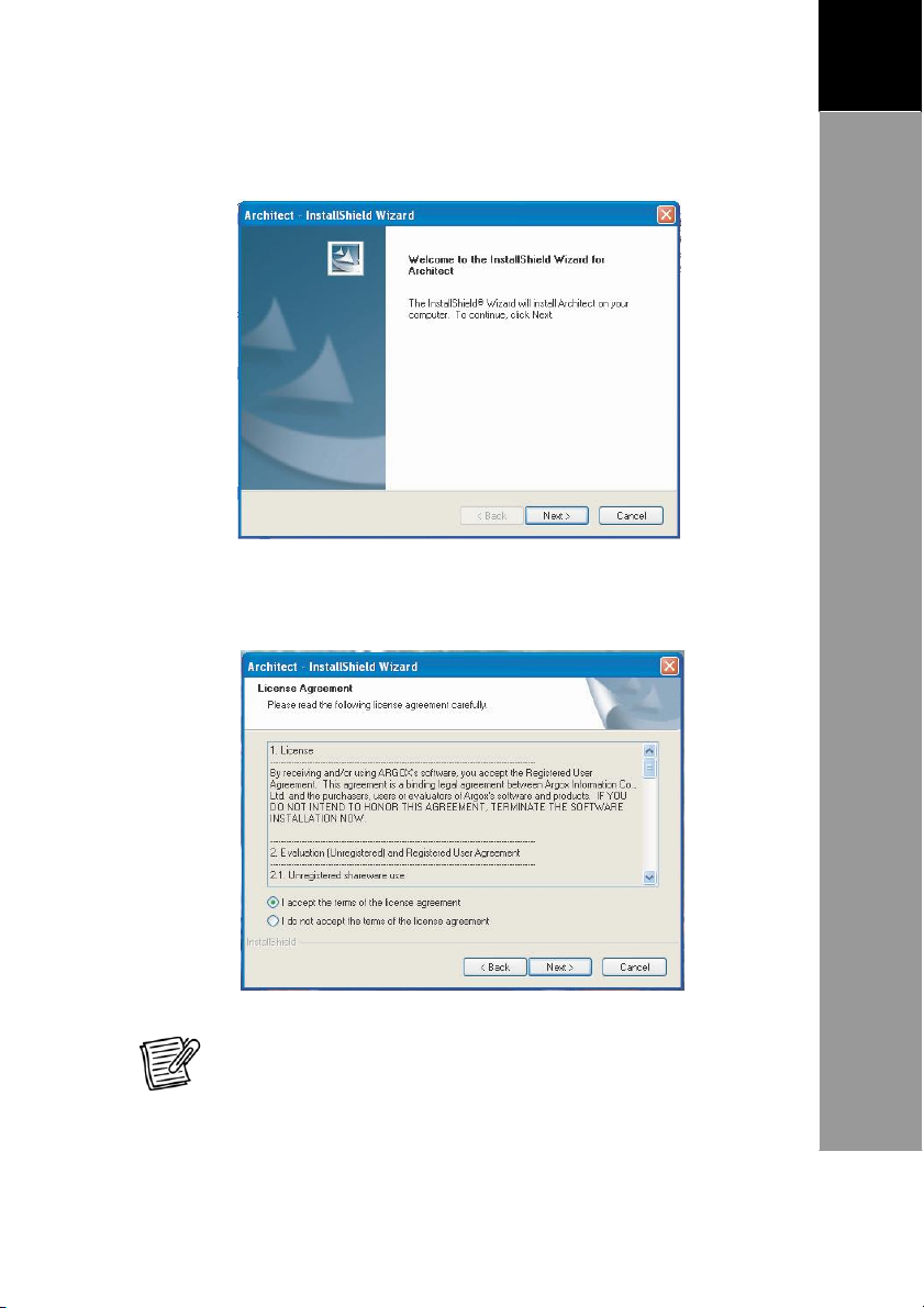
3.
The setup wizard
window below.
will
check your computer and display the
Click Next.
4.
Read the License Agreement. Click
the license agreement”,
“I accept the terms of
then click Next.
NOTE: The installation
the terms of the lic
will be cancelled if you click
ense agr
eement”.
“I do
not accept
Page 8
4
1
A
RCHITECT
®
U
SER’S
MANUAL
Introduction
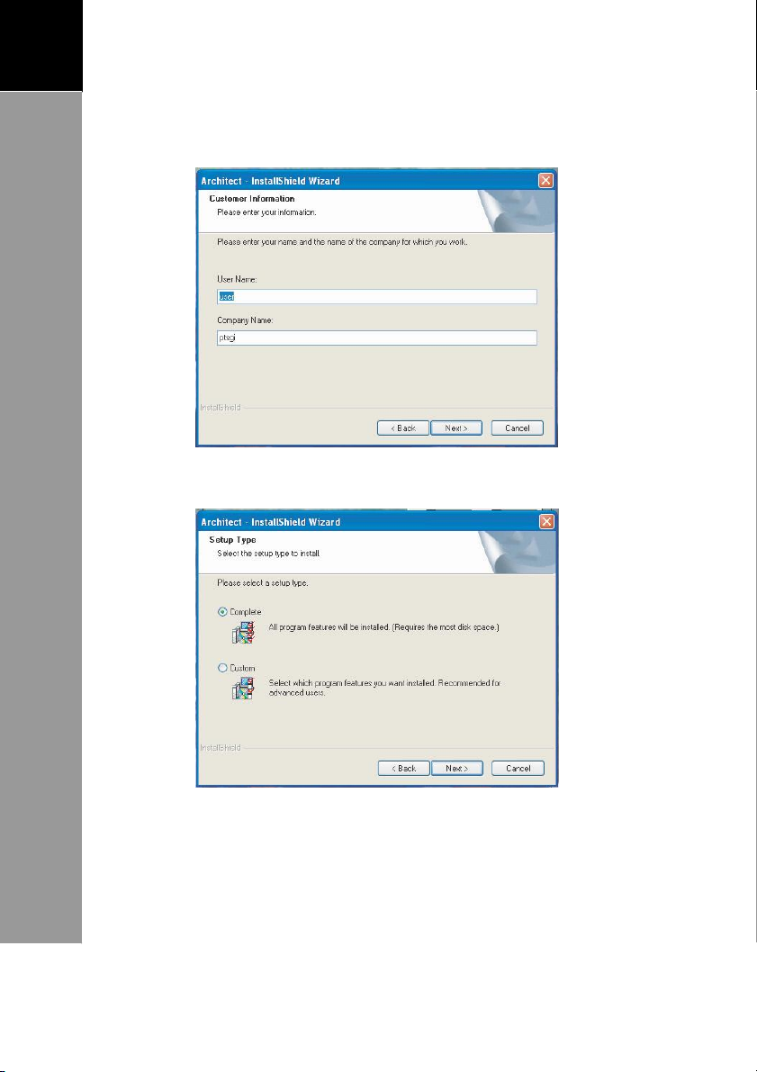
5.
Enter User Name and Company Name information, then
click Next.
6. Select the type of installation, then click Next.
Page 9
5
A
RCHITECT
®
U
SER’S
MANUAL
1
Introduction
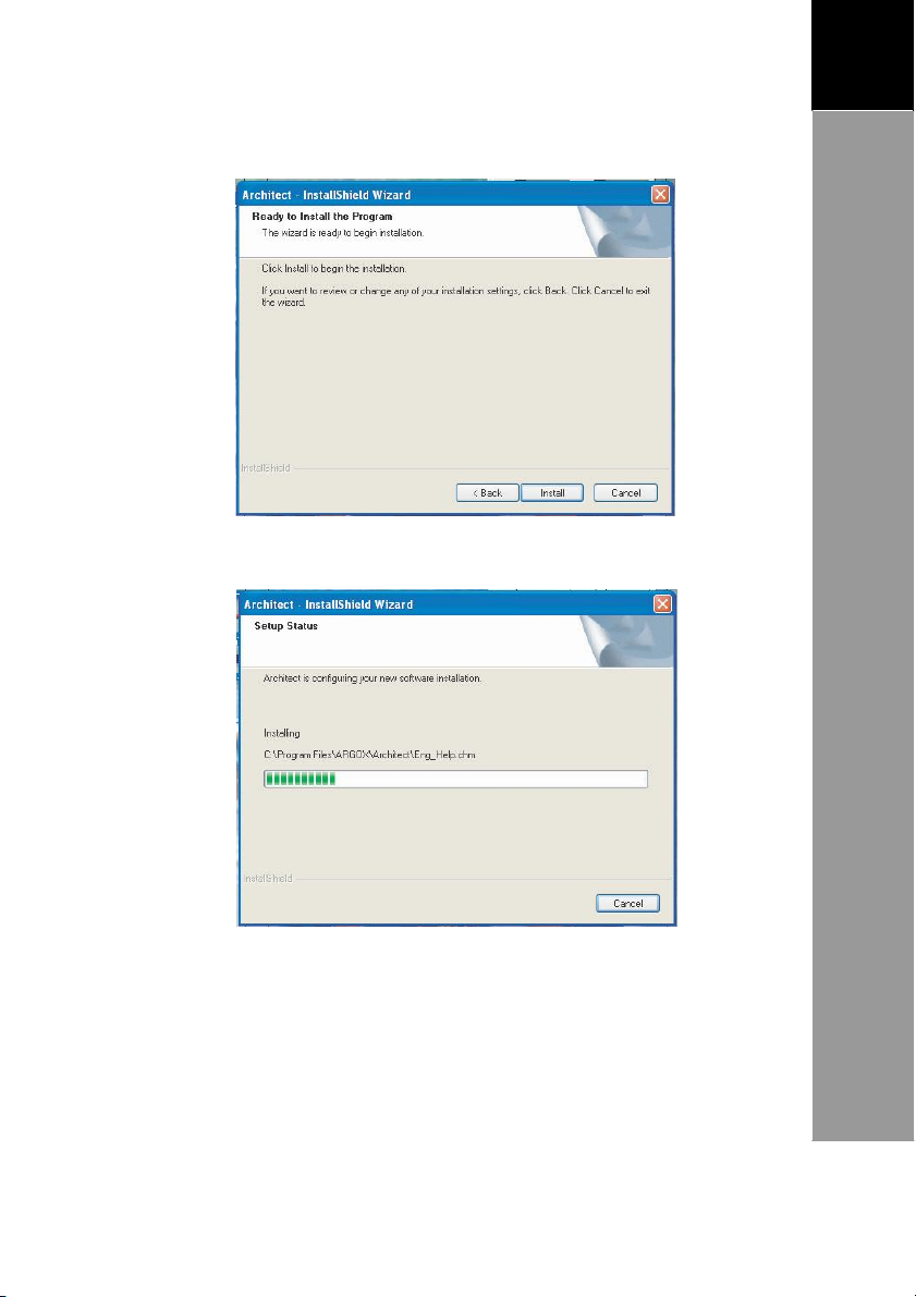
7. Click Install to begin installation.
8. The progress window appears.
Page 10
6
1
A
RCHITECT
®
U
SER’S
MANUAL
Introduction
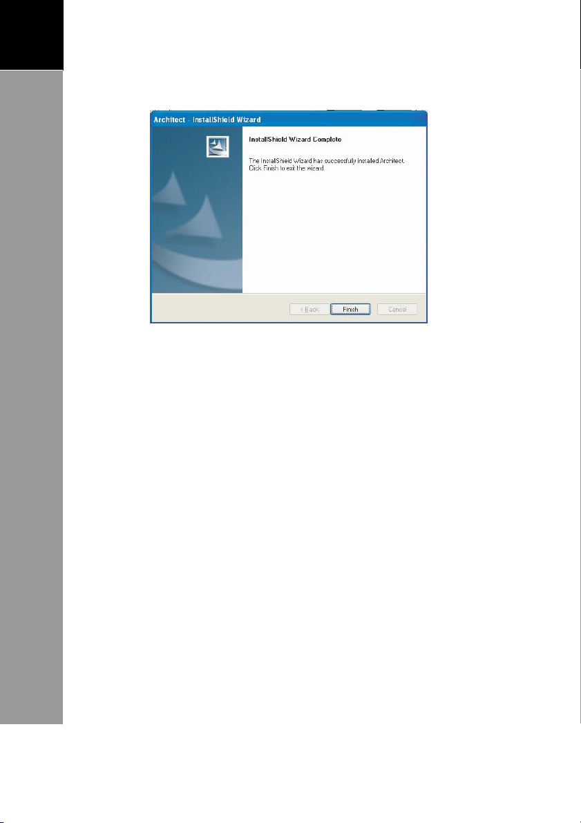
9. When setup is complete,
click Finish to exit the wizard.
Opening the Software
After installing the software, two shortcut icons should appear
on your desktop, Architect® and PT FileManager® . To
Architect® , double-click the desktop icon.
If the shortcut icons do not appear on
Start
button >All Programs or Programs > Argox
Applications >Terminal >Architect.
the desktop, click the
run
Page 11
7
A
RCHITECT
®
U
SER’S
MANUAL
2
Architect®
Interface
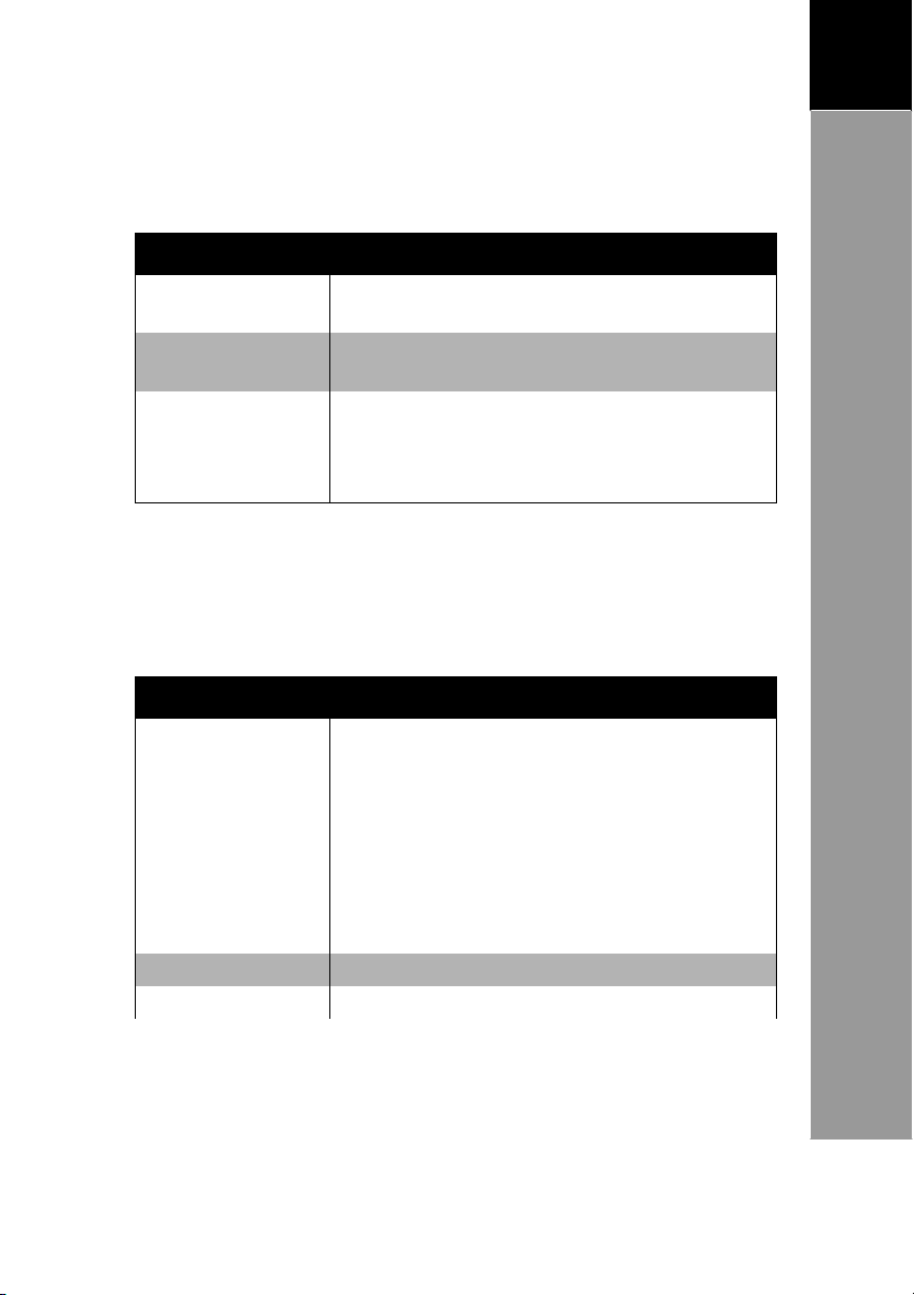
Submen
u
Shortcut K
ey Description
New Ctrl + N
Creates a new pr
oject.
Open
Ctrl + O
Opens an exis
ting pr
oject.
®
Chapter 2: Ar
This
chap
ter de
scribes
toolbars and windows. It is important to be
functions to maximize the features of Architect® .
Main
T
oolbar
Nodes
T
oolbar
chitect
the Architect user in
Interface
terface: main menu,
familiar with these
Status Bar
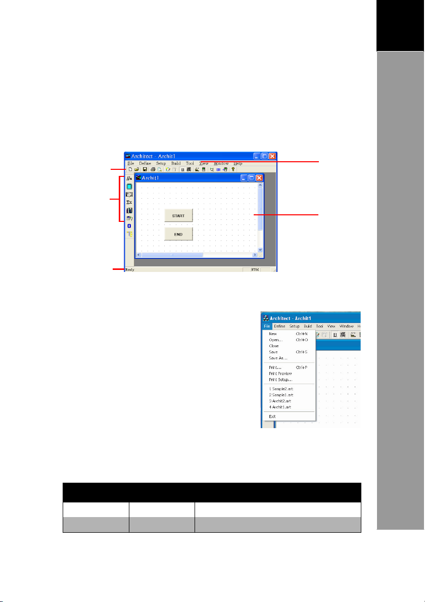
Main Menu
The main menu appears at the top of
the application window. It
the following menu items:
Define , Setup , B
Window and
The Ar
chichtect® App
lication I
nterface
consists of
File
,
uild , T
Help
ool , View,
Main
Menu
Project
window
File
Menu
Page 12
8
2
A
RCHITECT
®
U
SER’S
MANUAL
Architect®
Interface
Submen
u
Shortcut K
ey Description
Close
Closes
the current pr
oject.
Save Ctrl + S
Sa
ves the pr
oject.
Save As
Sa
ves the project to a new file.
Print Ctrl + P
Prints the visual representation of the
proj
ect.
Print Pr
eview
Pr
eviews the visual repr
esentation of
the pr
oject.
Print Setup
Sets printer pr
operties
.
Exit
Closes the software program
.
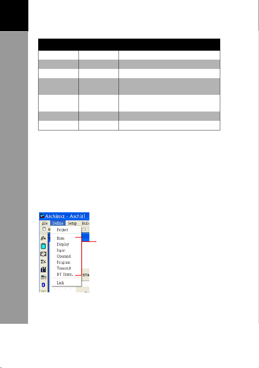
Define
The Define Menu is used to create and setup records and nodes
of the project. It consists of
Note, Display,
and Link. To
click
for
To
Menu
De
fine >
more information.
add nodes, click Define > the node you want to add.
the following submenu: Project
Inp
ut,
Operand, Program, Transmit,
view and modify the project and record settings,
Project.
See
“Creating
After you select any of these items, move
the mouse pointer to the project window
notice that the mouse icon corresponds to
the node that you selected, then click on
the area where you want to place the
See
“Step
page 14 for more information.
a
New
Project”
1:
Configure Project Settings”
BT Trans
on
page 14
,
,
node.
on
Page 13
9
A
RCHITECT
®
U
SER’S
MANUAL
2
Architect®
Interface
Submen
u Description
New Recor
d
Creates a new file to save the data records. See
“Step
4: Create the Record
File”
on
page 35
.
Record
Setting
Views and modifies ex
isting record settings.
See
“Step
4: Create the Record
File”
on
page 35
.
Co
mmun
icate
Configures the
communication port where
the
Terminal is co
nnected and sets baud rate. See
“Step
6: Configure
the Co
mmunication Setti
ngs”
on
page 40.
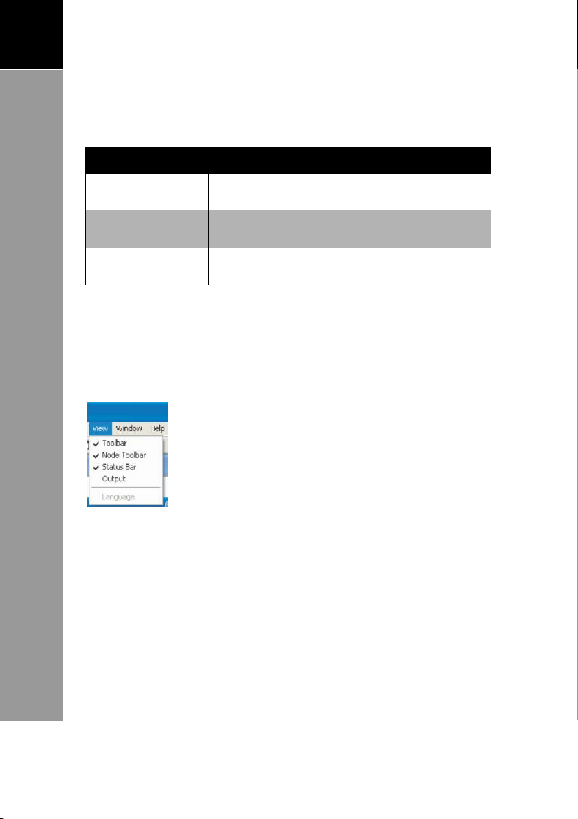
Submen
u Description
Compile
Compiling means to process an
information to form usable codes that
the
Terminal understands. After a project
has
been compiled it is now an
application.
To
compile a project, click Build >
Compile. An
Output window appears to
list any errors. See
“Compile
the
Project”
on page 38 for more information.
Batch Build
Build the project for faraway user.
Build Security
Data encryption while compile project.
Setup Menu
The Setup Menu is used to co
communication settings.
To
access these items, click a submenu to open its window.
nfigure file records and
Build Menu
The Build Menu is used to compile a project and create batch
files.
Page 14
10
2
A
RCHITECT
®
U
SER’S
MANUAL
Architect®
Interface
Submen
u Description
Simulator
Loads the Simulator to test
how the application
will
run on the Terminal.
Download
Opens the PT FileManager to download the
app
lication to
the Terminal.
Download BI
Opens the PT FileManager to download the Basic
Interpre
ter file
.
T
ool Menu
The T
ool Menu is used to si
application.
See
“Step
5:
Compile and
mulate and download an
Simulate”
on
page 38.
View Menu
The View Menu allows you to display or hide the following:
T
oolbar,
Window Menu
Node T
oolbar,
Status Bar,
When you click on an item, a checkmark
appears indicating that the item has been
selected to be displayed on the Architect®
application window. To hide
item.
Output,
and Language.
it,
uncheck the
The Window Menu allows you to define how you want the
project windows to be displayed. It has the following options:
•
Cascade: Displays project wi
ndows on top of the other
.
Page 15

11
A
RCHITECT
®
U
SER’S
MANUAL
2
Architect®
Interface
•
Tile: Displays project windows on a tile format without
overlapping each other
.
Opened projects are listed here. A checked file name
Help Menu
indicates that the
project is activated.
The Help Menu contains help topics
of Architect® .
T
oolbars
The T
oolbars act as short
Main T
Icon
oolbar
Operation
New
Open
Save
Print
Print Pr
New Record
Record Setup
One-byte
Two-byte Font
eview Pr
Font Selects a o
cuts for common functions.
Crea
tes a new pr
Opens an ex
Saves the proj
Prints the visual repres
eviews how
printed.
Creates a new record file.
Views and modifies record se
ne-byte font
Selects a two-byte font format.
and the software version
Descri
ption
oject.
isting pr
oject.
ect.
entation.
the visual repr
format.
esentation will be
ttings.
Build
Ac
tivates the compiler to
compile the project
.
Page 16

12
2
A
RCHITECT
®
U
SER’S
MANUAL
Architect®
Interface
Icon
Operation
Simulator
Co
mmunication Sets the co
Download BI
Do
wnload
Help
Ac
tivates the Simulator to test
application will run on the Terminal.
where the Terminal is conn
Ac
tivates the PT Fi
Basic Interpreter
Ac
tivates PT F
application to the Terminal.
Displays
the software vers
Descri
ption
how the
mmunication port and the
ected.
leManager to download the
file.
ileManager to download the
ion.
baud rate
Page 17

13
A
RCHITECT
®
U
SER’S
MANUAL
2
Architect®
Interface
Icon
Node
Descri
ption
Note
Cr
eate a note no
de. The note
created will not
be
displayed on the Termina
l
Display
Cr
eate a disp
lay no
de. See “Display
Node”
on
page 17.
Input
Create an input n
ode. See “Input
Node” on page 20.
Operand
Cr
eate an operand node. See
“Operand Node”
on page 26.
Program
Cr
eate a program node. See “Program
Node” on page 29.
Transmit
Create a transmit node. See
“Trans
mit Nod
e”
on
page 30.
BT trans.
Create a Bluetooth Transmission node on
page 31.
Link
Cr
eate a link node. See
“Step
3: Create
Links”
on
page 32.
Node T
Understanding the functions of these nodes is vital in
designing a project.
Windows
oolbar
There are two types of windows in Architect® :
•
Project Window: The interface where you design a project.
It consists of START
grid on the window.
•
Output Window: The output window displays any
information, errors or warnings when you compile a
project. See
“Compile
and END points. Dotted lines appear as
the Proj
ect”
on
page 38.
Page 18

14
3
A
RCHITECT
®
U
SER’S
MANUAL
Creating
a
New
Project
Chapter 3: Creating a New Project
Follow the steps below to create a new project:
Step 1: Configure Project Settings.
Step 2: Create Nodes.
Step 3: Create Links.
Step 4: Create the Record File.
Step 5: Compile and Simulate.
Step 6: Configure the Communication Settings.
Step 7: Download the Application to the Terminal.
See page 17.
See page 32.
Step 1: Configure Project Settings
To
open the settings page, click De
click on a blank area on the project window.
General Page
Define the color of each node as you want it to appear on the
project window.
1.
Click on a color to open the color palette and select the
desired color. To apply the default setting, click [De
2.
Define Programming Keys P1 & P2 ,if project requested
Ch
eck to display the
status bar on the
display node screen as
it appears on the
Terminal screen. See
page
18.
3.
Click [OK].
See below
See page 35.
See page 38.
fine >
Project or double
.
See page 40.
See page 41.
fault]
.
Page 19

15
A
RCHITECT
®
U
SER’S
MANUAL
3
Creating
a
New
P
roject
AID Setup Page
Use the AID Setup page to confi
the Agency ID (AID) or password on the Terminal before
accessing the application.
1.
Select Check
function.
2.
3.
Type your own error message or
4.
Record Page
See
Font Tool Page
Use the Font Tool page to
font image in project, if you use font
file in
Barcode Page
Enter the AID or Password.
use the pr
Click [OK].
“Step
4:
Create the Record
Program Node.
AID to enable the
e-defined
message.
make the
gure and require users to enter
File”
on
page 35.
Use the Barcode page to
the general barcode
project. Options
the barcode
panel.
configure
settings of the
vary depending on
type selected on the
left
Page 20

16
3
A
RCHITECT
®
U
SER’S
MANUAL
Bluetooth Page
Use the Bluetooth page to
the general
the
connect device.
Bluetooth
settings of
Lookup Page
Use the lookup page to
lookup file.
setup the
configure
Page 21

17
A
RCHITECT
®
U
SER’S
MANUAL
3
Creating
a
New
Project
Step 2: Cr
A node referes to a function or an operation that the Terminal
exe
cutes. Ar
Input, Operand, Program, Transmit, BT Trans. and Link.
Note Node
A Note node allows users to add comments that are shown on
the project window.
not displayed on the Terminal screen. This node is useful for
adding notes about the project for future reference or
maintenance.
To
add a Note node, do the following:
1.
From the Node toolbar,
2.
Move the mouse pointer to the project window.
the mouse pointer turns .
eate Nodes
chit
ect® supports
This node does not affect the project and is
eight kinds of nodes: Note,
click the Note node icon.
Notice that
Display,
3.
Click on an area to place the note. The Note screen
appears.
4.
Type your comments. To
color,
5.
Click [OK]. The note is displayed on the project window.
Display Node
Use the Display node to design text layout and co
displayed on the Terminal screen.
To
create a display screen, do the following:
1.
From the Node toolbar,
2.
Move the mouse pointer to the project window.
the mouse pointer turns
click [Advance].
NO
TE: To
move the no
position.
change the font, style, size and
te, click and drag the node to your desired
ntents to be
click the Display node
.
icon.
Notice that
Page 22

18
3
A
RCHITECT
®
U
SER’S
MANUAL
Creating
a
New
P
roject
3.
Click on an area to place the display node.
4.
The Di
splay screen appears.
Page Tabs
See page 20.
5.
On
(ver
the Display page, click anywhere inside the Screen
window,
Indicates the X
(horizontal) and Y
tical) position of
the mouse pointer
on the Termi
screen. The value
ch
ange as the
mouse
around window.
nal
moves
the Edit screen appears.
s
Sc
reen win
Click here to add
text.
The Terminal’s
Status Bar, as
it appears on
the Terminal
screen.
Screen
Window
dow
Page 23

19
A
RCHITECT
®
U
SER’S
MANUAL
3
Creating
a
New
Project
6.
To add text, click [Add Text].
screen appears. Type the text on the Text Data
window and
7.
8.
9.
10. Click [OK]. A display node is shown on the project window.
if necessary.
Type text here.
Displays cu
font settings.
Click [OK].
window and click on an area to
To show other input value, click [Add Object].
On
rrent
desired object from the box, and click [OK].
mouse pointer within the Screen window and click on an
area to place the object. The object’s
by .
Click [OK]
the Display tab,
•
Dis
play in (time) second: To specify the amount of time
to display the text.
•
Any key to next object: To display the text until a key
is
pressed.
modify the font type, size, and color
Move the mouse pointer within the Screen
when done.
click either of the following:
The Text Input
place the text.
position is indicated
Select available
font settings
here.
Select to
font
and color.
Move the
modify
type, size,
Select the
Page 24

20
3
A
RCHITECT
®
U
SER’S
MANUAL
Creating
a
New
P
roject
P
age Tab
Descriptio
n
General Page
Type your pref
erred n
ode name.
Co
mment Pa
ge
Type any comments or notes for this node. The
info
rmation here
will not be shown nor
affect the
Terminal
.
Disp
lay Page
As described above, tap
here to add text to b
e
displayed on
the Term
inal.
Link Pa
ge
Shows and lets you adjust how the nodes ar
e
connected. See
“Step
3: Cr
eate
Links”
on page 32
.
Other Display Node Settings
Other Display node settings can be changed using the different
tab pages.
Input Node
An Input node allows users to select the device source, the
data type, range and initial values of input. The data gathered
from this function can be saved to a re
Create the Record
To
add an Input node, do the following:
1.
From the Node toolbar,
2.
Move the mouse pointer to the project window.
the mouse pointer turns .
3.
Click on an area to place the node. The Input screen
appears.
4.
On
5.
the Display page, define the pr
displayed on the Terminal. See page 18,
Drag to adjust the position
of
the display text and the
input
File”
location .
on
cord file. See
page 35.
click the Input node
ompt message to be
“Step
icon.
Notice that
steps 5 to 9.
4:
Page 25

21
A
RCHITECT
®
U
SER’S
MANUAL
3
Creating
a
New
Project
NO
TE: The po
text will appear on the Terminal screen when input is finished.
6.
Click the Input tab.
The picture below shows the Input Device page.
Click an item here
to configure.
Device
Click Device to select the input device. Options are:
•
•
•
•
Setting
Click Setting to define the data type and its limitations
which is allowed for input. This function verifies the type
of input received from the Terminal and is used to control
Keypad:
Scanner: Select to use scanner as the input source.
Check the
require
after
scanning a barcode.
Keypad
as the input source.
Date &
parameters appears on screen. Select the format you
prefer.
sition of the
Select to use keypad as the input source.
“ENTER”
users to press the ENT key on the Terminal
&
Scanner: Select to use
Time: When you select Date
input loca
Configure the settings then click [OK].
to
confirm in
tion
is
where
Scanner to
keypad or scanner
&
Time, the Format
the input
Page 26

22
3
A
RCHITECT
®
U
SER’S
MANUAL
Creating
a
New
P
roject
Option
Ex
ampl
e Description
String
a, A, 1a
Alphanumeric characters can be entered.
Float
2.5,
12
.65
Digits with a decimal point can be
entered. Only a maximum of 6 decima
l
digits can be en
tered.
In
teger
5, 4,
0
Numeric characters
without
fr
actional or
decimal po
ints can be entered
2147483647-2147483648.
Passwor
d
ky1212
A password
entry is requir
ed.
the program flow.
status is set as “T
“Fa
•
il”.
NO
see page 31.
Data Ty
TE: For more
When the settings are met, the Node
rue”. Otherwise, the Node status is set as
information about the link and node status,
Click the
the type of input data.
Available parameters
may vary depending on the
Data Type selected.
pe: Select the type of input data required.
button to selec
here
t
Page 27

23
A
RCHITECT
®
U
SER’S
MANUAL
3
Creating
a
New
Project
•
Bound: Set the limit of input entry.
Option
Length
Range
•
Password:
Initial V
Click Initial Va
from the list.
Available options and their parameters may vary depending
on the data type selected.
In
itial Value
None
Constant
Enter the re
parameter is shown only when Pass
data type is selected.
alue
lue then the box to select the type of value
Check the box to enable the set length
function, then enter
length of characters. This function is
available only for String and Integer.
Check the box to
function, then enter
of digits.
Integer.
quired
No initial value is set.
Select this option to enter a specific
value.
Description
the allowable
enable the set range
the allowable range
This function is ava
password
Description
here.
Click to select the
type of initial value
from
ilable only
This
wor
d
the li
st.
for
Page 28

24
3
A
RCHITECT
®
U
SER’S
MANUAL
Creating
a
New
P
roject
In
itial Value
From Data Node
Se
lect this option to set
another node as
Description
the value of
the initial value.
Lookup File
Fo
rmula
7.
To compare input entries, click the Check up tab
Select this option to set the initial value
from a key n
Select this option to set the initial value
from the result of a formula equation.
Enter the fo
ode entry or f
rmula after “V
ile.
ariable =”.
Page 29

25
A
RCHITECT
®
U
SER’S
MANUAL
3
Creating
a
New
Project
P
age Tab
Descriptio
n
General Page
Type your pref
erred n
ode name.
Co
mment Pa
ge
Type any comments or notes for this node. The
info
rmation here
will not be shown nor
affect the
Terminal
.
This function compares the input entry from the Terminal
to a field in a file or a condition set by the user.
check up condition is met, the Node status is set as “T
Otherwise, the Node status is set as “F
NOTE: For
The parameters shown on the screen varies
the option selected.
Check up
None
Lookup in f
Lookup in Record
Condition Define
Other Input Node Settings
Option
ile
more
information about Node status, see page 32
Does not perform the check up
function.
Select this option to compare
to a field in a record file.
Click [S
earch] to select the file.
Select the Loca
from
the list.
Select the Separator
Enter the
Select this option to compare
to a field of a record.
Select the re
list.
Select this option to compare
based on
user.
Enter the
ail”.
Description
tion in the terminal
Field No. to
cord and the
the co
ndition defined by the
condition after “Result =
When the
depending on
the input
among the list.
compare.
the input
field
from
the input
rue”.
the
“.
.
Page 30

26
3
A
RCHITECT
®
U
SER’S
MANUAL
Creating
a
New
P
roject
P
age Tab
Descriptio
n
Check Up Page
Allows you to enter condit
ions to compare
with
the
input entries. See step 7
above.
Link Pa
ge
Shows and lets you adjust how the nodes ar
e
connected.
See
“Step
3: Cr
eate
Links”
on page 32
.
Operand Node
The Operand node is use to calculate math
and compare the results.
To
create an operand node, do the following:
1.
From the Node toolbar,
2.
Move the mouse pointer to the project window.
the mouse pointer turns .
3.
Click on an area to place the node. The Operand screen
appears.
4.
On
displayed on the Terminal. See page 18,
5.
Drag to adj
the
location .
the Display page, define the pr
display text and the operand
NO
TE: The po
resulting value will appear on the Terminal scr
click the Operand node
ust the position of
sition of the
operand location icon
ematical equations
ompt message to be
steps 5 to 10.
Notice that
is
een.
icon.
where
the
Page 31

27
A
RCHITECT
®
U
SER’S
MANUAL
3
Creating
a
New
Project
6.
Click the Operand tab.
below shows the Operand Setting page.
Configure the settings. The picture
Setting
Select whether the resulting va
an Integer or Float.
Initial V
Click Initial Va
from the list. Available options
vary depending on the data type selected.
alue
In
itial Value
None
Constant
From Data Node
lue of the operation
lue then the box to select the type of value
and their parameters may
Description
No initial value is set.
Select this option to enter a specific
value.
Se
lect this option to set
another node as
the value of
the initial value.
will
be
Fo
rmula
Select this option to set the initial value
from the result of a formula equation.
Enter the fo
rmula after “V
ariable =”.
Page 32

28
3
A
RCHITECT
®
U
SER’S
MANUAL
Creating
a
New
P
roject
P
age Tab
Descriptio
n
General Page
Type your pref
erred n
ode name.
Co
mment Pa
ge
Type any comments or notes for this node. The
info
rmation here
will not be shown nor
affect the
Terminal
.
Link Pa
ge
Shows and lets you adjust how the nodes ar
e
connected.
See
“Step
3: Cr
eate
Links”
on page 32
Logistics
Click Logistics then select the operation to perform from
the li
multiplication (*), division (/), or a
7.
To add comparison conditions, click the Compare tab.
Select and define the condition. Options are:
•
•
Greater than (>)
•
Greater than or equal to (>=)
•
Less than (<)
•
Less than or
•
Equal to (==)
•
•
User Define: Enter a user-defined equation.
Other Operand Node Settings
st. Operations
None
Not equal to (!=)
NO
TE: The result of this
program flow.
With Node
Cl
ick here to
equal to (<=)
include: ad
select the n
ode to use as an operand.
function can be used to
dition (+), subtraction
user-defined equation.
Select operation
With Constant
Select to enter a
constant value.
here.
control the
(-
),
Page 33

29
A
RCHITECT
®
U
SER’S
MANUAL
3
PRINT "Input price"
Creating
a
New
Project
P
age Tab
Descriptio
n
General Page
Type your pref
erred n
ode name.
Co
mment Pa
ge
Type any comments or notes for this node. The
info
rmation here
will not be shown nor
affect the
Terminal
.
Link Page
Shows and lets you adjust how the nodes are connected. See “Step 3:
Create Links” on page 32
Pr
ogr
am Node
The Program node is designed
knowledge. With this node, users
Basic commands.
To
create a program node, do the following:
1.
From the Node toolbar,
2.
Move the mouse pointer to the project window.
the mouse pointer turns .
3.
Click on an area to place the node. The Program screen
appears.
4.
On
5.
the Program tab,
GOSUB FN_GetPrice
Click [OK]
when done.
Other Program Node Settings
for users with programming
can define and execute PT
click the Program node
type the Basic
commands to execute.
Type the Basic commands
here.
For exa
mple, to
an
other node, named GetPri
type the command
FN_GetPr
For more information about
the Basic
the Basic
documen
ice”.
commands, refer t
Interp
tation.
icon.
Notice that
exec
ute
“GOSUB
reter
-
ce,
o
Page 34

30
3
A
RCHITECT
®
U
SER’S
MANUAL
Creating
a
New
P
roject
P
age Tab
Descriptio
n
General Page
Type your pref
erred n
ode name.
Co
mment Pa
ge
Type any comments or notes for this node. The
info
rmation here
will not be shown nor
affect the
Terminal
.
Link Pa
ge
Shows and lets you adjust how the nodes ar
e
connected.
See
“Step
3: Cr
eate
Links”
on page 32
.
Transmit Node
The Transmit node is used to call up remote link while running
an application in the Terminal.
To
create a transmit node, do the following:
1. From the Node toolbar, click the Transmit node icon.
2. Move the mouse pointer to the project window.
3. Click on an area to place the node. The
appears.
4. On the
Transmit
5. Click [OK] when done.
Other Transmit Node Settings
tab, select the
Port
Transmit
and
Baud rate
screen
.
Page 35

31
A
RCHITECT
®
U
SER’S
MANUAL
3
P
age Tab
Descriptio
n
General Page
Type your pref
erred n
ode name.
Co
mment Pa
ge
Type any comments or notes for this node. The
info
rmation here
will not be shown nor
affect the
Terminal
.
Link Pa
ge
Shows and lets you adjust how the nodes ar
e
connected.
See
“Step
3: Cr
eate
Links”
on page 32
.
Bluetooth Transmission Node
The
Bluetooth Transmission
To
create a bluetooth transmission node, do
node is used to transfer data.
the following:
1. From the Node toolbar,
2.
Move the mouse pointer to the project window.
click the
BT Trans.
node
Notice that
the mouse pointer turns .
3. Click on an area to place the node. The BlueTooth
Transmission screen appears.
4. On the
Bluetooth Transmission
tab,
select the
Bluetooth Transmission and fill out the file name.
5.
Click [OK]
when done.
Other Bluetooth Transmission Node Settings
icon.
Page 36

32
3
A
RCHITECT
®
U
SER’S
MANUAL
Step 3: Cr
eate Links
After creating the different nodes, you are now ready to
connect them to using the Link node. Link nodes control the
program flow.
note node) on the project wi
There should at least be two nodes (except a
ndow to create a link. The
connection flow from one node to another is indicated by
directional arrows.
To
create links, do the following:
1.
From the Node toolbar,
2.
Move the mouse pointer to the project window.
the mouse pointer turns .
3.
Click a node (except a note n
another node to connect.
This link node indicates that after performing
the display node (Demo_Display), the input
4.
A
directional arrow appears to indicate link.
NOTE: There
create a link no
click the Link node
node (Item_ID) is activated.
should at
least be two nodes on the proj
de.
icon.
Notice that
ode) then drag the mouse to
Drag to link Item ID to Warning1.
ect window to
Page 37

33
A
RCHITECT
®
U
SER’S
MANUAL
3
Creating
a
New
Project
5.
To configure link conditions, double-click one of the
connected node to open the
node’s
page. Click the Link
tab.
Linked
nodes are
displ
ayed here.
Tap “+” to
expand the list.
Check to clear
the Terminal
sc
reen afte
performing the
node’s
r
function.
Parameters
Link In
Link
Out
Condition
Lists
the connected nodes that pr
n
ode.
Lists the
to
Select an op
the next pr
•
•
•
connected n
after
completing its pr
ocess of the program. Options are:
Key:
Checks the key press from the Terminal.
Verify Node: Ch
status can be: Pass
Data Input (for Input
input data.
Description
odes that
ocess.
tion to set conditions
Click the Keypad
to activate the keypad
window
ecks the
Always, Fail, Succeed.
node only): Checks th
Type the required data in
the Input
Select condition
option here.
Parame
depending on
se
lected
condition.
Check this item
and select the
record to save
data.
eceded the active
the active n
and determine
and enter key.
node status. Node
text
box.
ters vary
ode goes
textbox
e
Page 38

34
3
A
RCHITECT
®
U
SER’S
MANUAL
Creating
a
New
P
roject
Parameters
Description
Cl
ear when
leave
Check this item to clear the Terminal screen after
performing
the n
ode’s
function
.
Write Record
Check this item to save the data to a re
cord file (.tx
t
or .dat). Select the record
from the list. See “Step 4:
Create the
Record
File”
on page 35.
6.
Click [OK] to close the page.
Page 39

35
A
RCHITECT
®
U
SER’S
MANUAL
3
Creating
a
New
Project
Items Descri
ption
Record na
me
Type the re
cord name
.
File Name
Define the file to save the record.
The file
should be a data (*.dat) or a text file (*.txt) I
f
you
assign a file that exists in the PC, it
will
be do
wnloaded to the Terminal.
Location
Se
lect the location where to
save the record
on the Terminal
.
Step 4: Cr
eate the Record File
A record is used to save input da
following:
1. On the main toolbar, click the New Record icon.
2. On the left panel, click
Cl
ick an option
to view page.
3.
Enter the required settings.
ta. To
Setting.
create a record, do
the
Page 40

36
3
A
RCHITECT
®
U
SER’S
MANUAL
Creating
a
New
P
roject
Items Descri
ption
Left
Column
Lists all the input nodes in the proj
ect.
Right Co
lum
n
Move the input n
odes to be saved as fields
of
the record.
The data will be saved in the
same sequen
ce. Use the
“Up”
and “Down
”
butt
ons to sort
the sequence.
Ov
erwrite record with
Check this item to ov
erwrite the specified
record field. If left unchecked, the new data
will be recorded at
the end of
the file.
4.
On
the
left
The screen should look something like this:
Left
Column
Right Column
panel, click Field.
Define the fields of the
Click to
the items to
the
left or
right column.
record.
move
5.
On
the
left
panel, click Separator.
Select how you want the fields to be
list.
If
Length is selected, you
each
field.
separated from the
need to set the
len
gth of
Page 41

37
A
RCHITECT
®
U
SER’S
MANUAL
3
Creating
a
New
Project
6.
For notes and maintenance purposes, click Comment on
the
left
7.
Click [OK]
NO
click Setup >
panel and type your comments on the box.
TE: To
main too
when done.
access the Record
lbar or double-click a
Record
setup anytime, click
nywhere on
Setting.
the project window or
the
icon on th
e
Page 42
38
3
A
RCHITECT
®
U
SER’S
MANUAL
Creating
a
New
P
roject
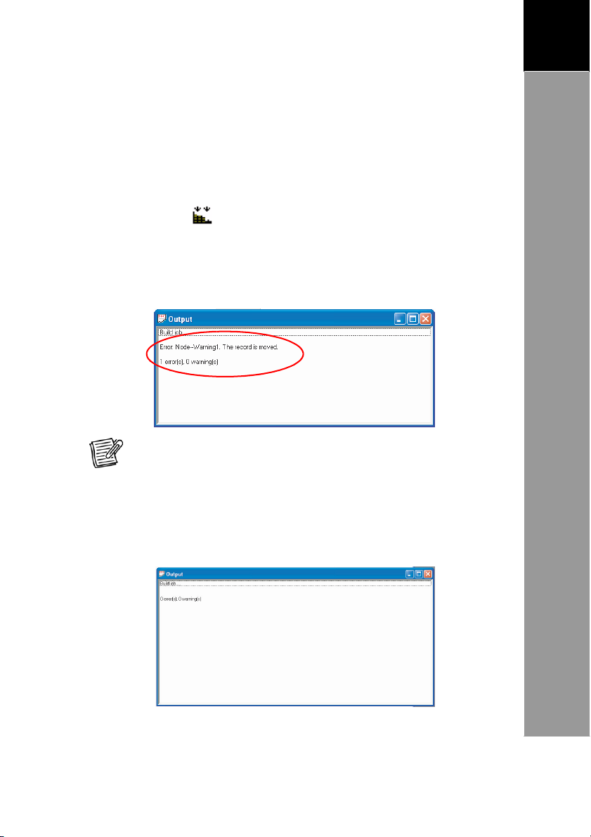
Step 5: Compile and Simulate
When the project flow is compl
project to check for errors.
Compile the Pr
Click the Build
appears and displays any errors or warnings. If errors occur
debug your project. The picture below is an example of an
output window that shows the number and the source of
errors.
NO
setting.
When the project is compiled successfully, an
program is created. When the
error(s), 0
ready to simulate the application.
TE: Dou
warning(s)”
ete, compile and simulate your
oject
icon to compile. The Output window
ble-click the error
message, see picture below,
message to direc
Output window shows the
tly go to the source
application
,
“0
you are now
Page 43

39
A
RCHITECT
®
U
SER’S
MANUAL
3
Creating
a
New
Project
Simulate the Application
With the Simulator,
when downloaded to a Terminal. Users
flow and match it to the users needs and expectations.
Simulating before downloading saves time for debugging at a
later time.
1.
2.
To turn on the Simulator,
3.
4.
5.
To close the Simulator,
Click the Simulator
Simulator is activated.
PW key.
Click 1,
the application.
The Terminal screen displays the
simulated application.
then the ENT key to run
NO
TE: If you enabled the Write Record
will save the data in the record file. The record file will be saved in
the install path \\Simulator\.
you can see
icon. The
click the
click .
how the application
can check
function, running Simulato
the program
will
work
r
Page 44

40
3
A
RCHITECT
®
U
SER’S
MANUAL
Creating
a
New
P
roject
Step 6: Configure
the Communication Settings
Before you download the applicati
the communication port settings.
1.
On
2.
3.
the main toolbar,
Select the Port and the Baud rate.
NO
TE: The Port is where the Terminal is c
The Baud rate set here should match the one set on the Terminal (see
the te
rminal’s
Click [OK]
user gu
ide manual).
when done.
on, you need to configure
click the Communication
onnec
ted to the computer
icon.
.
Page 45
41
A
RCHITECT
®
U
SER’S
MANUAL
3
Creating
a
New
Project
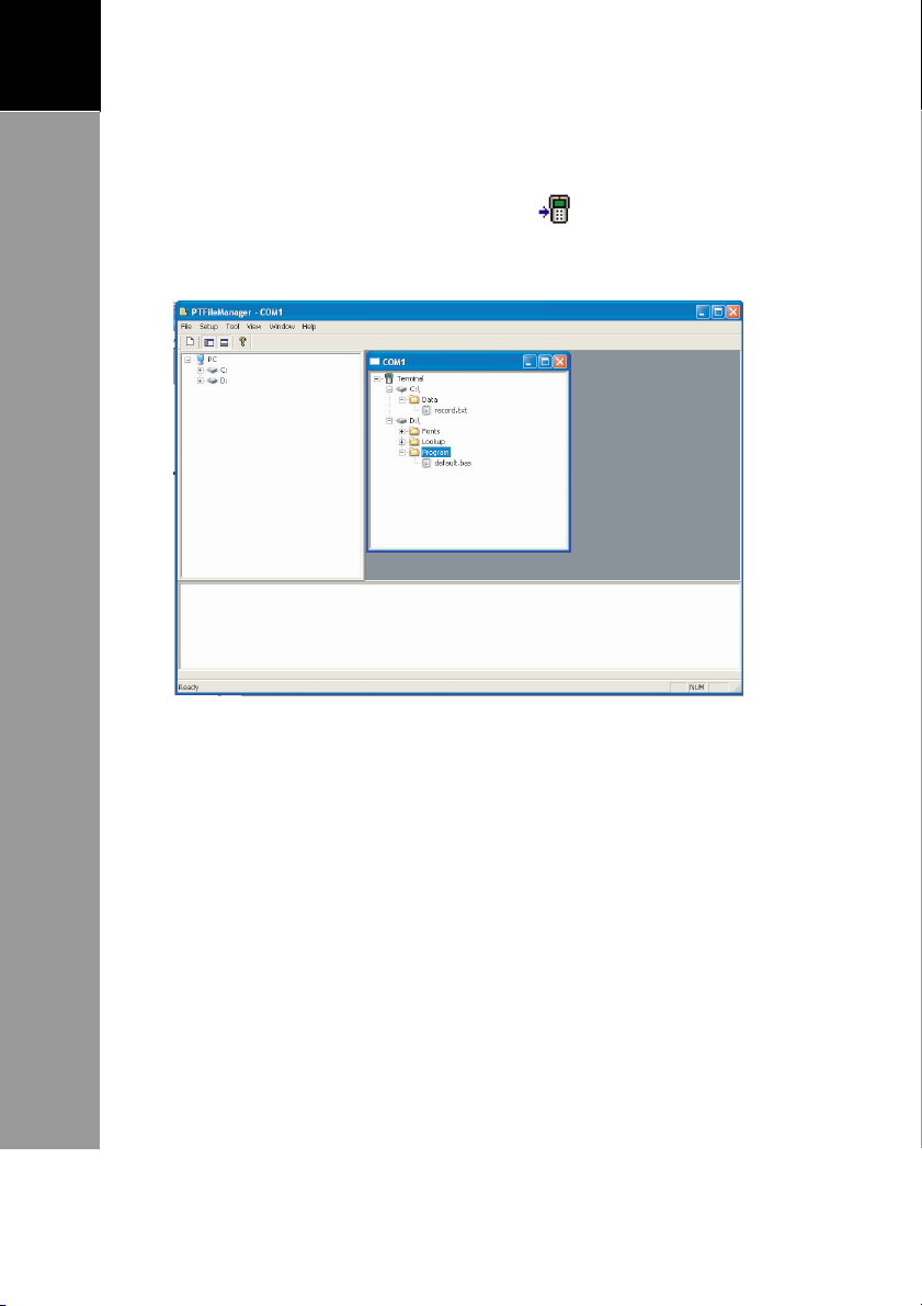
Step 7: Download the Application to the Terminal
To
download the application, click the
FileManager screen appears. The application is automatically
downloaded to the Terminal.
icon. The PT
For more information about the PT FileManager,
software’s
manual.
refer to the
Page 46

42
3
A
RCHITECT
®
U
SER’S
MANUAL
Sample
Project
Chapter 4: Sample Project
Below is a sample project that generates the total cost based
on the quantity and the
•
Demo_
•
Item_ID: This is an input node. The user enters the Item ID.
If the Item ID entered is invalid, the Terminal w
Error_ID (display node). The app
•
Quanti
valid, the Terminal
•
Amount: This is also an input node. After entering the
quantity, the user
Displ
ay: This is the display screen.
ty: This is an input node. If the Item_ID entered is
amount of an item.
lication
will
ask the user for the Quantity.
will
enter
the amount of the item.
will
start again.
ill execute
•
Total:
Quantity by
the total value is less than 500, the ADDCharge message is
displayed. If the total value is more than or equal to 500,
the application
This is an operand node.
the Amount and displays the total value. If
will
start from the Item_ID node again.
This node multiplies the
Page 47

43
A
RCHITECT
®
U
SER’S
MANUAL
4
Sample
Project
How to Make This Pr
1.
Create a display node as the
welcome screen. Name it
“
Demo_Display
2.
Create an input node.
•
Name it
•
Create the display screen.
”.
“Item_ID
oject
”.
•
Set the input settings.
The
input value can only
be
between 1-3.
3.
Create a display node.
•
Name it
•
On the display page, type
•
Set the display time to
“Error_ID”.
“2
“Stock
ID
second”.
error”.
Page 48

44
3
A
RCHITECT
®
U
SER’S
MANUAL
Sample
Project
4.
Create link nodes.
•
Link ST
•
Link Demo_Display to Item_ID.
•
Link Item_ID to Error_ID.
•
Link Error_ID to
•
Double-click Item_ID and
go to
•
Select Link out > Error_ID.
•
Select Condition: Verify
Node = Fail.
5.
Create an input node.
•
Name it
•
Create the display text and position the input location.
6.
Create another input node.
•
Name it
•
Create the display text and position the input location.
7.
Create an operand node.
ART to Demo_Display.
the Link page.
NO
TE:
The default Condition is Pass Always, thus it is
unnecessary to change Link In > Demo Display.
“Quantity”.
“Amount”.
Demo_Display.
•
Name it
•
Create the display text and position the operand location.
•
On the Operand page, configure: Data Type =
•
Select Initial V
Node = Quantity.
“T
otal”.
Integer;
alue > Intial = From
Data Node; Copy
Page 49

45
A
RCHITECT
®
U
SER’S
MANUAL
4
Sample
Project
•
Select Logistics > Oper
= * (multiplication);
Node = Amount.
•
On the Compare page,
configure: Condition = <;
With Con
8.
Create a display node.
•
Name it
•
Create the display text and set the time.
stant =
“ADDCharge
With
“500
”.
ator
”.
9.
Create link nodes.
•
Link Item_ID to Quantity
•
Link Quantity to Amount
•
Link Am
•
Link Total to
ount to Total.
ADDCharge
.
.
.
•
Link Total to
•
Double-click Item_ID and go to the Link page.
•
Select Link Out > Quantity > Condition = Verify
Node St
•
Double-click Total
•
Select Link Out > ADDCharge > Condition = Verify
Node St
10. Save the project.
11. Compile and simulate.
12. Download the application to the Terminal.
Item_ID
atus =
atus =
.
Succeed
Succeed.
.
and go to the Link page.
Node;
Node;
Page 50

46
4
A
RCHITECT
®
U
SER’S
MANUAL
:
Page 14
Page 32
Page 42
Page 44
 Loading...