

Page 1

Page 2
Page 3

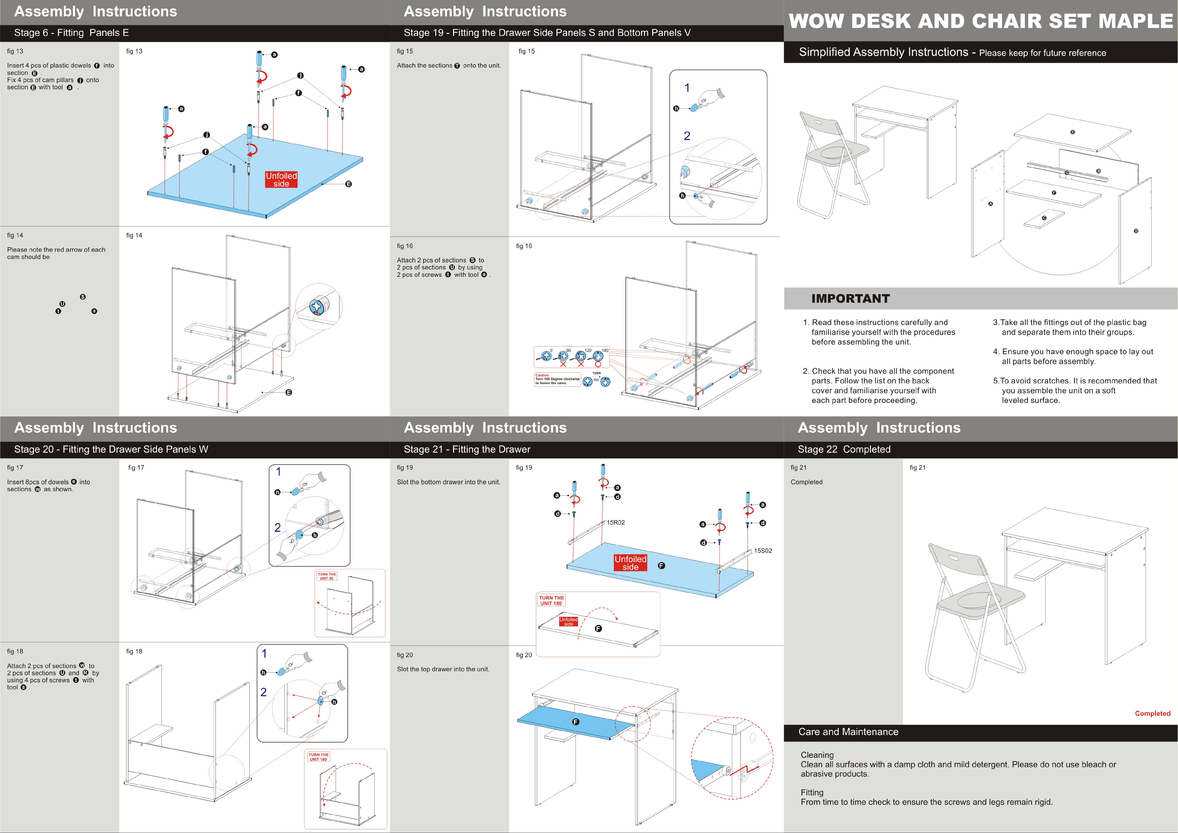
Gv Desk & Chair Set
Assembly Instructions - Please keep for future reference
617/1043
Desk Dimensions
Width - 74cm
Depth - 52.5cm
Height - 74.5cm
Important -
If you need help or have damaged or missing parts, call the Customer Helpline: 08456 400800
Please read these instruction fully before starting assembly
Chair Dimensions
Width - 47.5cm
Depth - 46cm
Height - 80cm
Issue 1 - 12/01/09
Page 4
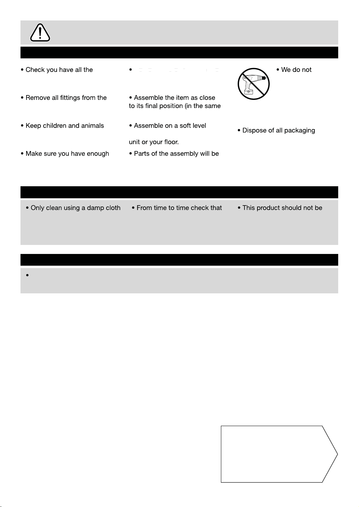
Safety and Care Advice
Important - Please read these instru ctions fully before starting assembly
Do not stand on the product,
components and tools listed on
pages 2 and 3.
plastic bags and separate them
into their groups.
this could cause damage.
room) as possible.
as this could damage the unit.
Only use hand screwdrivers.
recommend the
use of power
drill/drivers for
inserting screws,
away from the work area, small
parts could choke if swallowed.
space to layout the parts before
starting.
Care and maintenance
and mild detergent, do not use
bleach or abrasive cleaners.
Warning
For chair: The maximum safe
weight of user: 100kgs.
surface to avoid damaging the
easier with 2 people.
there are no loose screws on
this unit.
carefully and responsibly.
discarded with household
waste. Take to your local
authority waste disposal centre.
Note:
if required the next
page can be cut out and used
as reference throughout the
assembly. Keep this page with
these instructions for future
reference.
1
Page 5

Components - Panels
Please check you have all the pan els listed below
Left side
1
Right side
4
(47.6 x 72.6cm)
(47.6 x 72.6cm)
back panel
2
Top supporting bar
5
(23 x 70cm)
(2 x 70cm)
CD supporting panel
3
(14 x 38cm)
Top panel
6
(74 x 52.6cm)
Keyboard shelf
7
(67.6 x 29.6cm)
2
Page 6

If you have damaged or missing components,
Components - Fittings
call the Customer Helpline: 08456 400800
Please check you have all the fittings listed below
Note: The quant it ies below are the correct amount to complete the assembly. In some cases more
fittings may be supplied than are required.
A
300mm Hand
Side Runner x 1
D
Cam x 4
G
17mm Sticker Cover x 14
J K
38mm Allen Screw x 2
Left
Tools required
Screwdriver
(Not included)
Allen Key
(included)
B
300mm Hand
Side Runner x 1
E
30mm wooden dowel x 9
H
300mm Right Hand
Side Runner x 1
37mm Cam Pillar x 4
Right
C
12mm Self-Tapping Screw x 8
F
38mm Self-Tapping Screw x 8
I
300mm Left Hand
Side Runner x 1
Ruler - Use this ruler to help correctly identify the screws
0 5 10 15 20 25 30 35 40 45 50 55 60 65 70 75 80 85 90 95 100 110 120105 115 125 130 135 140 145 150 155 160 165 170
3
Page 7
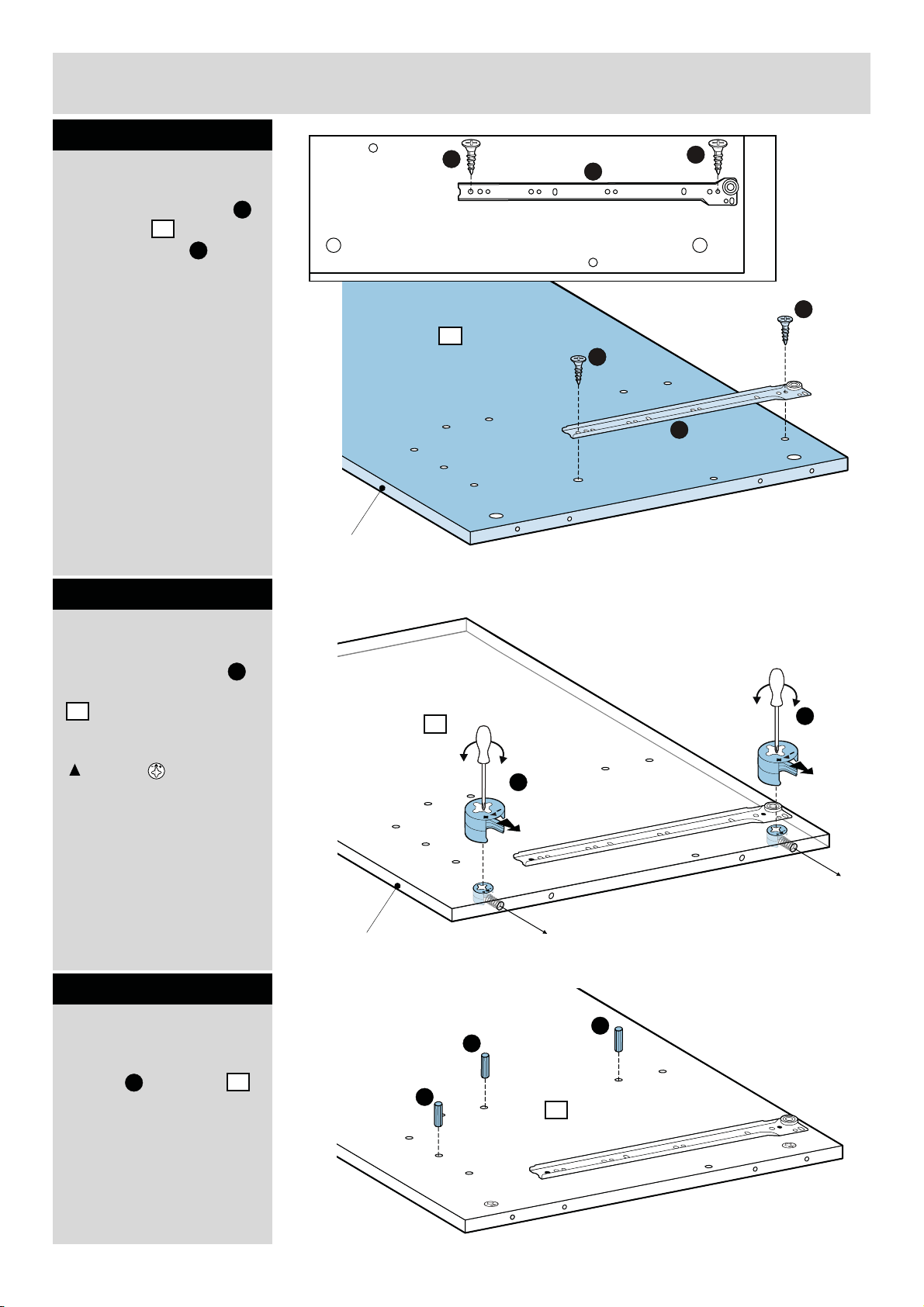
Assembly Instructions
Step 1
Attaching runners
C
A
C
Attach the left runner
onto panel by using
2pcs of screws with
1
C
screwdriver.
Step 2
Attaching cams
A
C
1
C
A
Unfinished edge
Insert 2 pcs of cams
D
onto the left side panel
1
.
Please adjust the arrow
on cam to correct
position as shown.
Step 3
Fitting dowels
Insert 3pcs of wooden
dowels into panel .
E
1
Unfinished edge
E
1
D
E
E
1
D
4
Page 8

Assembly Instructions
Step 4
Fitting dowel
Insert 1 pc of wooden
dowel onto back
panel .
E
2
E
2
Unfinished edge
Step 5
Attaching panels
Attach CD supporting
panel onto back
panel by using 2 pcs
of screws with
screwdriver.
3
2
F
F
F
Unfinished edge
2
3
5
Page 9

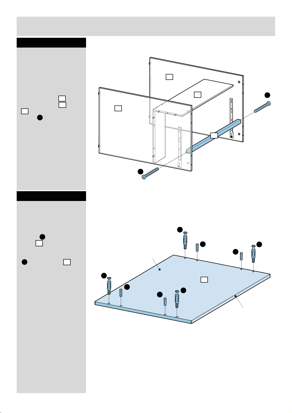
Assembly Instructions
Step 6
Attaching panels
Two people are required
here.
2
Attach left side panel
onto the panels &
1
2 3
by using 4 pcs of screw
F
with screwdriver.
F
F
1
F
3
F
Step 7
Attaching runners
Attach the right runner
B
onto right side
panel by using 2pcs
of screws with
screwdriver.
4
C
C
Finished edge
B
4
C
B
C
C
6
Page 10

Assembly Instructions
Step 8
Attaching cams
Insert 2 pcs of cams
D
onto the right side panel
4
.
Please adjust the arrow
on cam to correct
position as shown.
Step 9
Fitting dowel
Insert 1pc of wooden
E
dowel
side
into the right
panel .
4
Finished edge
4
D
E
4
D
Step 10
Attaching panels
Two people are required
here.
Assembled
side panel
panel & by using
2 pcs of screw with
screwdriver.
7
the right
4
onto the
2
1
F
F
4
2
1
F
Page 11
Assembly Instructions
Step 11
Attaching Supporting
bar
Two people are required
here.
Attach the top
supporting bar
between panel and
4
by using 2 pcs of
screw with Allen key.
J
5
1
Step 12
Attaching dowels &
cam pillars
4
2
1
5
J
J
Insert 4 pcs of wooden
dowels into top
panel .
E
6
Fix 4 pcs of cam pillars
K
into top panel
with screwdriver
6
.
K
E
Unfinished side
K
E
E
K
6
E
Unfinished edge
K
8
Page 12

Assembly Instructions
Step 13
Attaching panel
Two people are required
here.
Joint the top panel
6
to the unit by locking the
cams as shown.
D
Warning:
The unit is
heavy.
Lif t with care.
D
4
2
1
6
Unfinished side
Unfinished edge
4
1
2
6
0° 90° 120° 180°
TURN
180°
Caution:
Tur n 180 Degree clockwise
to fasten the cams.
9
Page 13

Assembly Instructions
Step 14
Attaching sticker
Attach sticker covers
G
onto the unit.
1
4
G
2
1
G
2
5
G
Step 15
Attaching keyboard
Attach 2 pcs of runner
I
& onto panel by
7
using 4 pcs of screws
with screwdriver.
H
C
C
H
C
H
Unfinished side
C
C
I
C
7
C
H
7
I
7
Unfinished edge
7
C
C
I
7
10
Page 14

Assembly Instructions
Step 16
Attaching keyboard
Slot the keyboard shelf
into the unit.
7
4
7
6
7
1
4
Step 17
Assembly is
complete.
20kgs Max
If you need help or have damaged or missing parts, call the Customer Helpline: 08456 400800
11
 Loading...