

Page 1
SHOULD YOU REQUIRE ANY ASSISTANCE WITH YOUR UNIT
YOU CAN CONTACT CUSTOMER SERVICES ON 01482 701173
Cornice
Assembly Instructions
Important! Please note, This cornice must
be firmly fixed to the carcass as instructed,
with the provided screws. Failure to do so
could result in the cornice falling off the unit
causing injury.
To Assemble this fitment you will need a posi-drive
screw driver, a hammer, a step ladder (or equivalent),
and one other person to assist.
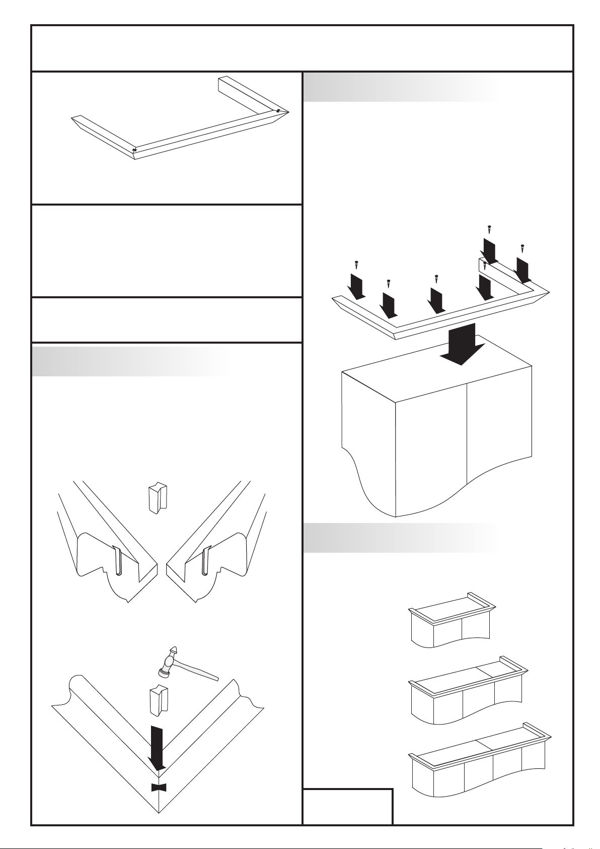
Cornice Joint Assembly
1
Fitting The Cornice
2
Place the cornice on top of the robe, you may
need to use step ladders to do this. Position the
cornice being careful to ensure that the back edges
of the cornice are flush with the back of the robe
and that the overhang on each side is equal. Once
the position is correct, screw down firmly with
a posi-drive screwdriver using the screws provided.
It may not be necessary to use all the screws in
the pack
Work on a clean, flat and firm surface.
Position a side cornice rail (one angled end)
and a front cornice rail (twin angled ends) together
to make a corner. Press the Plastic dovetail jointer
into the grooves in the cornice
Plastic Dovetail jointer
Cornice
Tap home firmly with a hammer to make the
joint tight. Repeat for the other corner
Cornice
Cornice Sizes
The cornice is fixed in the same way for a double
robe, three door run and a four door run.
Code: ST71500
Issue 4: 04/05/06
Page 2

Page 3

Door Alignment Instruction
Door Alignment Instruction
Height/ Level: The door can be
1.
adjusted up and down 1.5 mm.
Loosen all screw ‘A’s on all
hinge plates, level the door height
and re-tighten all screw ‘A’s.
Gap Between Doors: The gap
2.
can be adjusted 5.5 mm. First
loosen screw ‘B’, turn screw ‘C’
to Close the gap or anticlockwise
to increase the gap. Re-tighten
screw ‘B’ to lock the position.
Distance Away From Unit:
3.
This gap can be increased by up to
2.8 mm. Loosen off screw ‘B’, this
allows the hinge arm to slide back
and forth along the hinge plate. Adjust
as required then re-tighten screw ‘B’.
Height/ Level: The door can be
1.
adjusted up and down 1.5 mm.
Loosen all screw ‘A’s on all
hinge plates, level the door height
and re-tighten all screw ‘A’s.
1
2
3
Gap Between Doors: The gap
2.
can be adjusted 5.5 mm. First
loosen screw ‘B’, turn screw ‘C’
to Close the gap or anticlockwise
to increase the gap. Re-tighten
screw ‘B’ to lock the position.
Distance Away From Unit:
3.
This gap can be increased by up to
2.8 mm. Loosen off screw ‘B’, this
allows the hinge arm to slide back
and forth along the hinge plate. Adjust
as required then re-tighten screw ‘B’.
A
B
A
1
2
3
A
B
A
C
Code: Sy05370
Issue 1: 13/03/08
C
Code: Sy05370
Issue 1: 13/03/08
 Loading...