

Page 1
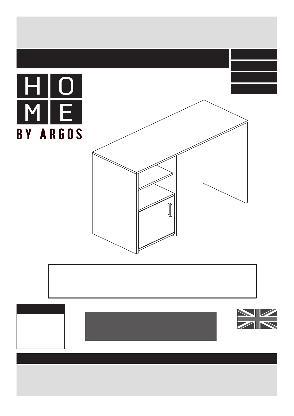
Lawson - Desk
Assembly Instructions - Important: Retain these instructions
for future reference
402/4439
412/6416
412/3392
797/7916
WARNING!
In order to prevent overturning, this product must be
used with the 2 wall attachment devices provided
Dimensions
Width - 100cm
Depth - 39.5cm
Height - 73.5cm
Important - Please read these instructions fully before starting assembly
If you need help or have damaged or missing parts, please visit www.argos-support.co.uk
or email: Help@ClickSpares.co.uk (quoting your original order number)
Alternatively, call the Spares Helpline on: 0370 112 1928.
For any other queries please contact the Customer Helpline on: 0345 640 2020
More help is available throughout this
booklet by scanning in the QR codes
or typing in the links
MADE IN
BRITAIN
Issue 8 - 05/10/17
Page 2

Safety and Care Advice
Important - Please read these instructions fully before starting assembly
• Warning: This unit weighs
approximately 20kgs.
Please lift with care.
• Assembly to be carried out by
a competent adult only.
• Check you have all the
components and tools listed on
pages 2 and 3.
• Remove all fittings from the
plastic bags and separate them
into their groups.
• During assembly children
should be kept away from the
product due to possible risk of
injury.
• Installation shall only be
carried out exactly according to
the manufacturer’s instructions
- otherwise a safety risk can
occur if incorrectly installed.
• Parts of the assembly will be
easier with 2 people.
• Make sure you have enough
space to layout the parts before
starting.
• Do not stand or put weight on
the product, this could cause
damage.
• Assemble the item as close to
its final position (in the same
room) as possible.
• Assemble on a soft level
surface to avoid damaging the
unit or your floor (use opened
out unit carton).
• We do not
recommend the
use of power
drill/drivers for
inserting screws,
as this could damage the unit.
Only use hand screwdrivers.
• WARNING: To prevent
possible overbalancing this unit
must be secured to a wall
using the 2 overbalance
protector kits supplied.
• Dispose of all packaging
carefully and responsibly.
• Do not use this item if any
components are missing or
damaged.
Care and maintenance
• Only clean using a damp cloth
and mild detergent, do no use
bleach or abrasive cleaners.
• Regularly check all fastenings
to ensure that they are properly
tightened.
• This product should not be
discarded with household
waste. Take to your local
authority waste disposal centre.
Note: If required the next page
can be cut out and used as
reference throughout the
assembly. Keep this page with
these instructions for future
reference.
1
Page 3
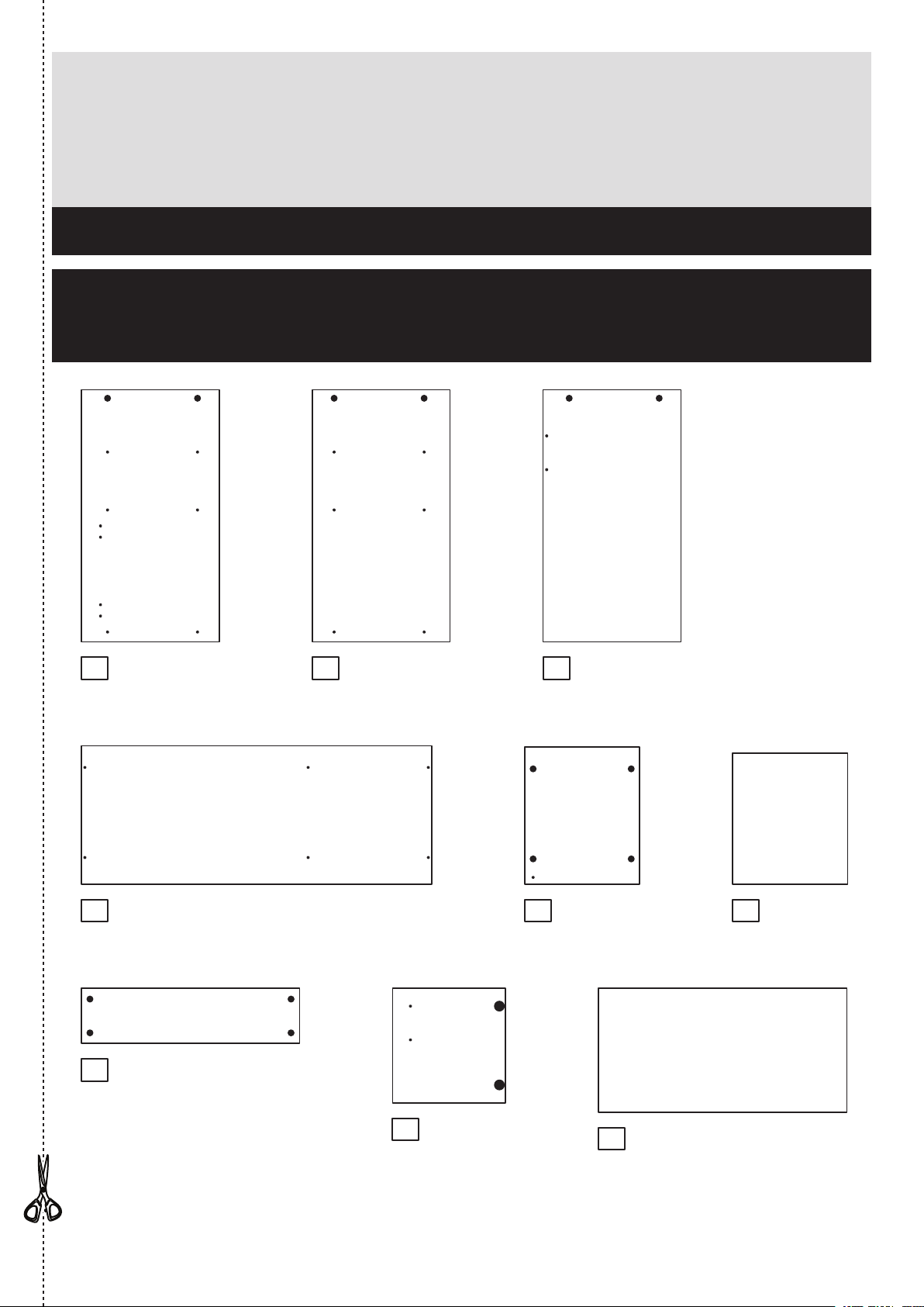
Components - Panels
If you need help or have damaged or missing parts, please visit www.argos-support.co.uk
or email: Help@ClickSpares.co.uk (quoting your original order number)
Alternatively, call the Spares Helpline on: 0370 112 1928.
For any other queries please contact the Customer Helpline on: 0345 640 2020
Please check you have all the panels listed below
When applicable, remove any protective film
from the panels before they are used
1 Left End
(71.6 x 39.2cm)
4 5 6
Top
(99.6 x 39.6cm)
7
Modesty (DF2772)
(62 x 15.7cm)
(DF2766)
(DF2765)
2 3
Upright (DF2767)
(71.6 x 39.2cm)
Right End (DF2768)
(71.6 x 39.2cm)
(DF2769)
Base
(32.7 x 39cm)
x 2
Shelf (DF2770)
(32.7 x 37.3cm)
8
Door (DF2771)
(32.6 x 32.1cm)
9
Back (X707-353)
(70.7 x 35.3cm)
2
Page 4
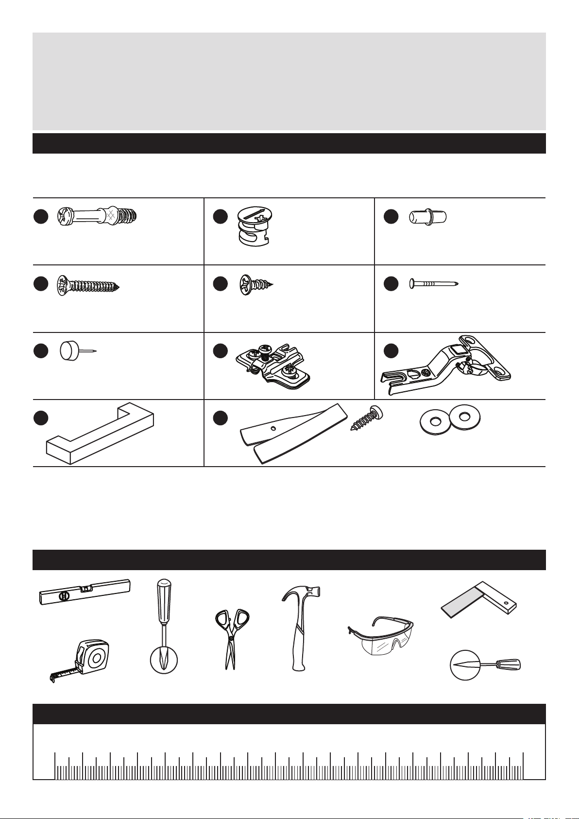
Components - Fittings
If you need help or have damaged or missing parts, please visit www.argos-support.co.uk
or email: Help@ClickSpares.co.uk (quoting your original order number)
Alternatively, call the Spares Helpline on: 0370 112 1928.
For any other queries please contact the Customer Helpline on: 0345 640 2020
Please check you have all the fittings listed below
Note: The quantities below are the correct amount to complete the assembly. In some cases
more fittings may be supplied than are required.
A B
Metal dowel (F901) x 18
D E F
13mm Screw (F63) x 425mm Screw (F50) x 2
G H
Plastic Nail (F91) x 6
J
Handle (F236) x 1
K
Strap Screw Washer x 2
Large locking cam
(F900) x 18
nut
Hinge plate
F523) x 2
(
Overbalance protector kit (F269) x 2
C
Shelf stud (F110) x 5
Nail (F51) x 14
I
Hinge (F522) x 2
Tools required
Spirit
level
Rule
Cross-head
screwdriver
Scissors Hammer
Eye protection
(when using a
hammer or drill)
Square
Bradawl
Ruler - Use this ruler to help correctly identify the screws
mm 10 20 30 40 50 60 70 80 90 100 110 120 130 140 150 160 170
3
Page 5
Assembly Instructions
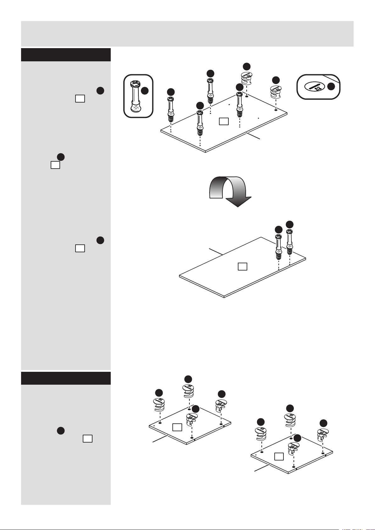
Step 1
Prepare the upright
Screw 4 metal dowels
into the upright .
2
Note: Tighten the metal
dowels up fully against
the panels.
Insert 2 large locking
cam nuts into the
upright .
B
2
A
A
A
B
A
B
A
A
2
Finished
front edge
B
Note: The arrow on the
locking cam nut must
point towards the hole in
the edge of the panel.
Turn the upright over
Screw 2 metal dowels
into the upright .
2
A
Turn the upright over
A
A
Finished
front edge
2
Step 2
Prepare the 2 base
panels
Insert 4 large locking
cam nuts into each of
the 2 base panels .
B
5
Finished
front edge
B
B
B
5
B
Finished
front edge
B
B
B
5
B
4
Page 6

Assembly Instructions
Step 3
Fit a base to the
upright
Push a base onto the
upright .
Use a screwdriver to
tighten the 2 large
locking cam nuts
fitted to the upright .
Note: Turn the large
locking cam nuts as
far as they will go - more
than 1/2 a turn.
5
2
B
2
B
2
Finished
front edge
A
B
5
Finished
front edge
Step 4
Fit the other base to
the upright
Push the base onto
the upright .
5
2
Use a screwdriver to
tighten the 2 large
locking cam nuts
fitted to the upright .
B
2
Step 5
Prepare the left end
Screw 4 metal dowels
into the left end .
1
Insert 2 large locking
cam nuts into the left
end .
B
1
Fit 2 hinge plates onto
the left end , making
1
sure that the slot is
facing towards the
finished front edge.
A
H
2
5
Finished
front edge
Hinge Fixing and Door Adjustment
www.youtube.com/watch?v=wIMhUHeLBtg
Finished
front edge
A
H
A
A
KH
H
1
B
B
A
5
Page 7

Assembly Instructions
Step 6
Fit the left end
Push the left end
1
onto the 2 base panels
. .
5
Use a screwdriver to
tighten the 2 large
locking cam nuts
B
fitted to each of the 2
base panels .
5
Step 7
Prepare the modesty
Insert 4 large locking
cam nuts into the
modesty .
B
7
5
1
5
Finished
front edge
B
B
Finished
top edge
7
B
B
Step 8
Prepare the right end
Screw 2 metal dowels
into the right end .
Insert 2 large locking
cam nuts into the
right end .
B
3
A
3
A
A
3
B
B
Finished
front edge
6
Page 8

Assembly Instructions
Step 9
Fit the modesty
Push the modesty
onto the upright .
7
2
Use a screwdriver to
tighten the 2 large
locking cam nuts
fitted to the modesty .
B
7
Note: Support the
modesty until the right
end has been fitted in
the next step.
Step 10
Finished
top edge
7
2
Fit the right end
Push the right end
onto the modesty .
3
7
Use a screwdriver to
tighten the 2 large
locking cam nuts
fitted to the modesty .
B
7
Step 11
Prepare the top
Screw 6 metal dowels
into the top .
4
A
7
3
Finished
front edge
A
A
A
A
A
4
Finished
front edge
A
7
Page 9

Assembly Instructions
Step 12
Fit the top
Push the top onto
the assembly.
Use a screwdriver to
tighten the 6 large
locking cam nuts
fitted to the left end ,
the upright and the
right end .
4
B
1
2
3
4
3
2
1
Step 13
Fit the back
a: Square up the unit by
making sure that
measurement x to x
equals y to y.
b: Place the back
onto the unit.
Nail around the
F
outside edges of the
back .
Note: Nails should be
spaced about 150mm
apart.
9
9
Squaring up a Chest and tting the Back Panel
www.youtube.com/watch?v=FeaI6541z7o
The measurement from top corner X to bottom corner X must be
a:
equal to the measurement from top corner Y to bottom corner Y
b:
F
x
x
9
y
y
xx
yy
8
Page 10

Assembly Instructions
Step 14
Fit the 6 plastic nails
Tap 2 plastic nails
G
into the bottom edge of
each of the left end ,
upright and right end
. .
3
2
1
Carefully stand the
unit up for the next
step.
Warning: The
unit is heavy.
Lift with care.
Step 15
Fit 4 shelf studs
Insert 4 shelf studs
into the holes shown.
C
G
3
G
G
G
2
G
1
G
Step 16
Fit the shelf
Lower the shelf down
onto the shelf studs .
9
6
C
x 4
C
6
Finished
front edge
Page 11

Assembly Instructions
Step 17
Fit the door stop
Push the remaining shelf
stud up into the hole
C
in the corner of the upper
base to act as a door
stop.
5
5
C
Step 18
Prepare the door
Push fit 2 hinges into
the door .
8
Secure each hinge with
2 screws .
E
Note: Before securing
with the screws, make
sure that the hinges are
positioned at 90 degrees
with the edge of the
door.
I
Hinge Fixing and Door Adjustment
www.youtube.com/watch?v=wIMhUHeLBtg
E
E
E
I
I
90
I
E
8
10
Page 12

Assembly Instructions
Step 19
Fit door and handle
Note: The easiest way to
attach the door is to
fit the top hinge first,
then align and fit the
other hinge.
a: Push the hinge
onto the front part of the
hinge plate .
The recess at the bottom
of screw B goes into the
slot in the hinge plate.
b: Keep the hinge
FLAT against the hinge
plate as you slide it
across as far as it will go.
Tighten screw A.
H
8
I
H
I
Hinge Fixing and Door Adjustment
www.youtube.com/watch?v=wIMhUHeLBtg
a: b:
I
c: d:
I
H
H
H
I
B
I
H
I
A
H
B
c: The hinge must be
flat against the hinge
plate prior to any
adjustment.
H
d: The hinge must
NOT be AT AN ANGLE
to the hinge plate
when assembled.
This would indicate that
the recess at the bottom
of screw B had not
located in the slot in the
hinge plate and the hinge
would not be secure.
Remove the hinge from
the hinge plate and then
re-assemble being
careful to follow
instructions a-c.
e: Attach a handle to
the door using 2
screws .
D
I
I
H
J
8
e:
D
8
J
D
11
Page 13

Assembly Instructions
Step 20
Adjust the door if
needed
a: Before adjusting the
door, use a spirit level to
check the top (or base)
of the unit is level,
front-to-back and
side-to-side in the 3
positions shown.
Use suitable packing
pieces (not supplied) to
make the unit level
BEFORE making any
adjustment to the hinges,
as shown.
b: Height adjustment.
Loosen screws A on
hinge plates and move
door up or down as
required.
Retighten screw A.
Hinge Fixing and Door Adjustment
www.youtube.com/watch?v=wIMhUHeLBtg
a:
b:
A
A
c:
c: Forward and Back
adjustment.
Loosen screw B on hinge
plate and move door in
or out as required.
Retighten screw B.
d: Sideways
adjustment.
To move door ‘out’
loosen screw C.
To move door ‘in’ tighten
B
d:
C
12
Page 14

Assembly Instructions
Step 21
Fit the 2 overbalance
protector kits
To prevent possible
overbalancing this unit
must be secured to a
suitable wall by fitting of
the 2 overbalance
protector kits , one
either end of the
modesty panel.
Wall fixings are not
supplied as they will
need to suit the wall
type.
Take care when
Note:
drilling the wall that you
do not drill into any
pipes, wires etc.
If in doubt, consult an
expert.
K
In order to prevent overturning
this product must be used with the
2 wall attachment devices provided
(not supplied)
WARNING!
Example
Modesty Panel
Wall fixing
Washer
Screw
K
Washer
Screw
(not supplied)
Assembly is complete
See the next page for a guide
to wall mounting and fixings
If you need help or have damaged or missing parts, please visit www.argos-support.co.uk
or email: Help@ClickSpares.co.uk (quoting your original order number)
Alternatively, call the Spares Helpline on: 0370 112 1928.
For any other queries please contact the Customer Helpline on: 0345 640 2020
13
Page 15

A Guide to Wall Mounting & Fixings
Important note:
If plastic wall plugs
are supplied with your
product:
- these are only suitable for
use in masonry walls.
If you are in any doubt about
the correct wall plugs for
your wall, seek professional
advice.
Failure of the product due to
using incorrect fixings is the
responsibility of the installer.
Important: When drilling into walls always
check that there are no hidden wires or pipes etc.
Make sure that the screws and wall plugs being used
are suitable for supporting your unit. Consult a qualifed
tradesperson if you are unsure.
Hints:
1: General rule: Always use a larger screw and wall plug
if you are not sure.
2: Ensure you use the recommended drill bit to match the wall
plug and hole size.
3: Ensure you drill the hole horizontally, do not force the drill or
enlarge the hole.
4: Take extra care when drilling high walls, ceilings and ceramic
tiles. Ensure wall plugs are inserted beyond the thickness of
the ceramic tiles to avoid the tiles splitting or cracking.
5: Ensure wall plugs are well fitted and are a tight fit in the
drilled hole.
Types of walls
You can use one of the following types of wall plug if your
walls are made of brick, breeze block, concrete, stone or wood.
No.1 “General Purpose” wall plug No.3 “Cavity Fixing” wall plug No.5 “Hammer Fixing” wall plug
Generally aerated blocks should not
be used to support heavy loads, use
a specialist fitting in this case. For light
loads, general purpose wall plugs can
be used.
No.2 “Plasterboard” wall plug
For use with plasterboard partitions or
hollow wooden doors.
No.4 “Cavity Fixing-Heavy Duty”
wall plug
For use with walls stuck with
plasterboard. The hammer fixing allows
it to be fixed to the wall rather than the
plasterboard. Always check the fixing
is secure to the retaining wall.
No.6 “Shield Anchor” wall plug
Heavy loads
For use when attaching light loads on
to plasterboard partitions.
Care &
Maintenance
For use when fitting or supporting
heavy loads such as shelving, wall
cabinets and coat racks.
Safety: Always check the fitting
and location to ensure your safety
in and around the home.
For use with heavier loads such as TV
& HiFi speakers and satelite dishes etc.
Fitting: From time to time check
the fitting to ensure the wall plugs
or screws do not become loose.
14
Page 16

ALR3189
 Loading...