

Page 1
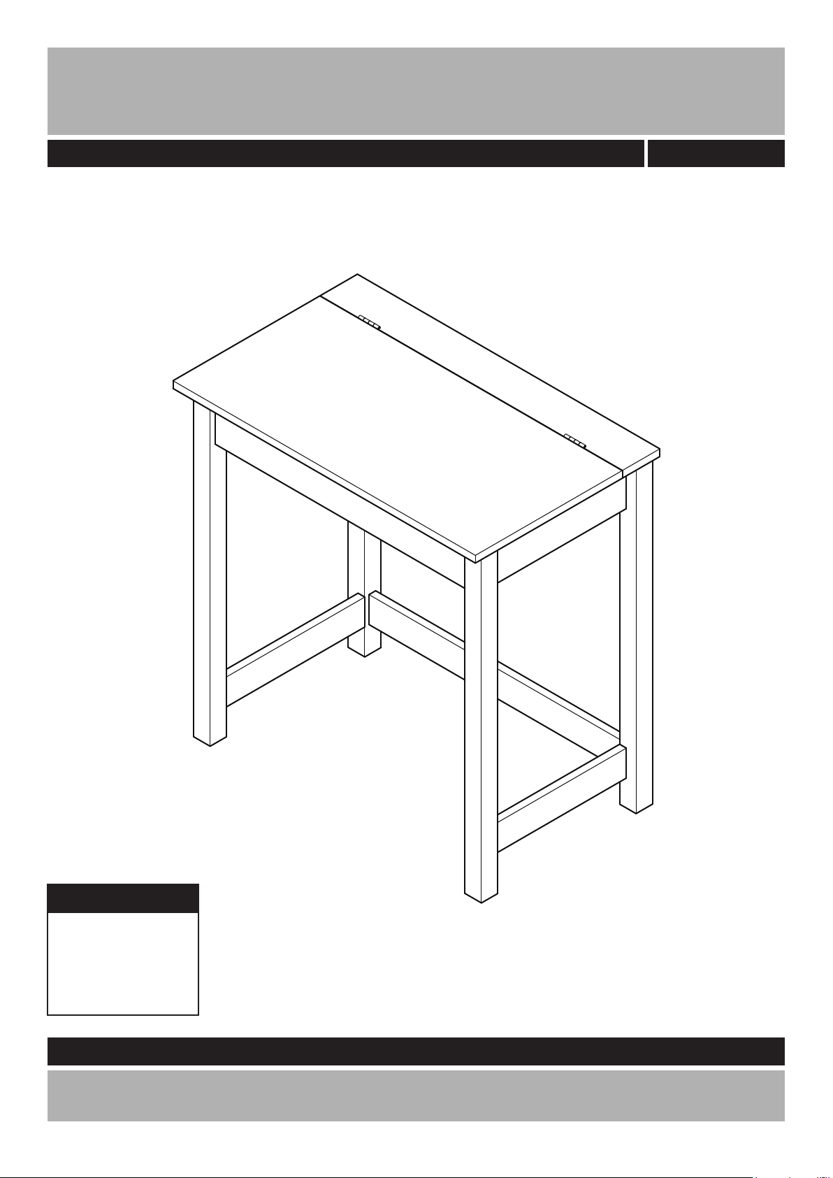
Denbigh Desk
Assembly Instructions
-
Please keep for future reference
170/5720
Dimensions
Width - 70cm
Depth - 43cm
Height - 72cm
Important - Please read these instructions fully before starting assembly
If you need help or have damaged or missing parts, call the
Customer Helpline: 08456 400800
Version 2
Date: 21/10/13
Page 2

Safety and Care Advice
Important - Please read these instructions fully before starting assembly
• Check you have all the
components and tools listed on
pages 2 and 3.
• Remove all ttings from the
plastic bags and separate them
into their groups.
• Keep children and animals away
from the work area, small parts
could choke if swallowed.
• Make sure you have enough
space to layout the parts before
starting.
• Do not use this item if any
components are missing or
damaged.
Care and maintenance
• Only clean using a damp cloth
and mild detergent, do not use
bleach or abrasive cleaners.
• Do not stand on the product,
this could cause damage.
• Assemble the item as close to
its nal position (in the same
room) as possible.
• Assemble on a soft level surface
to avoid damaging the unit or your
oor.
• Parts of the assembly will be
easier with 2 people.
• From time to time check that
there are no loose screws on
this unit.
• We do not
recommend the
use of power
drill/drivers for
inserting screws,
as this could damage the unit.
Only use hand screwdrivers.
• Dispose of all packaging
carefully and responsibly.
• This product should not be
discarded with household waste.
Take to your local authority waste
disposal centre.
Note: if required the next
page can be cut out and used
as reference throughout the
assembly. Keep this page with
these instructions for future
reference.
1
Page 3
If you have damaged or missing components,
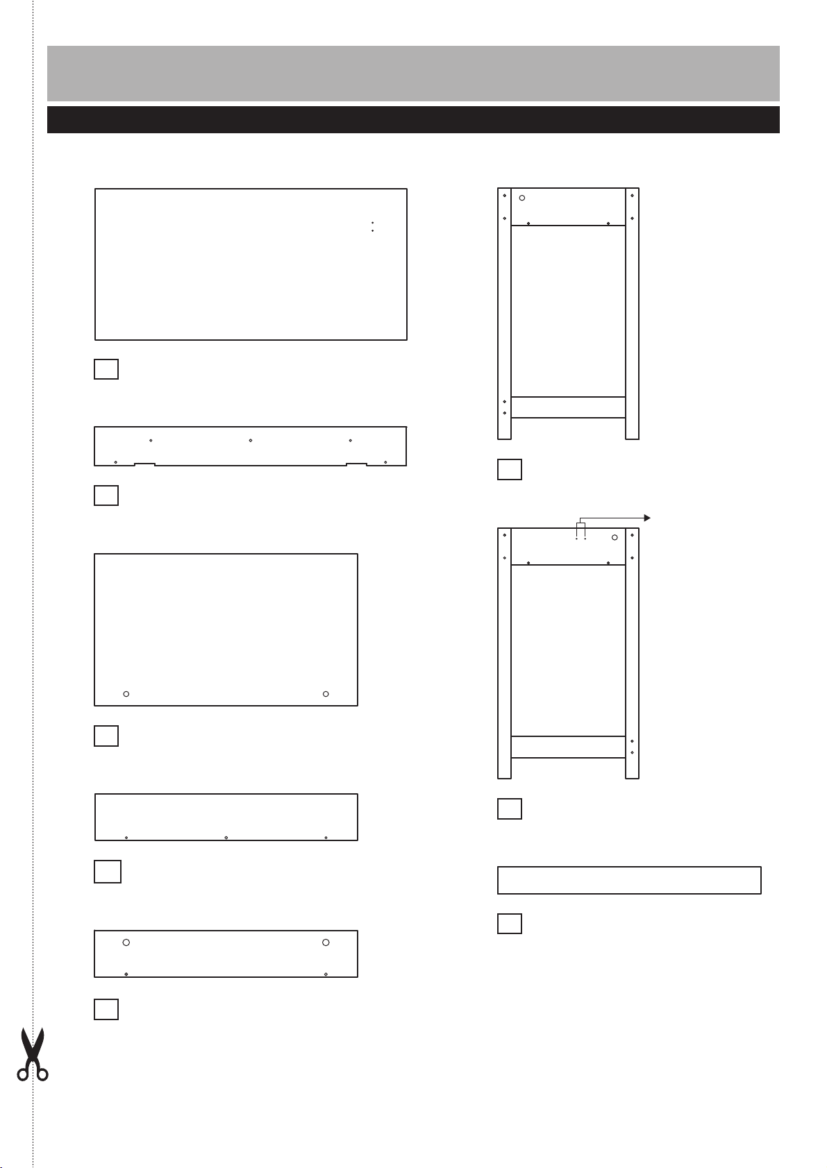
Components - Panels
call the Customer Helpline: 08456 400800
Please check you have all the panels listed below
1
Small top panel
2
Bottom panel
3
(70 x 34cm)
(70 x 8.6cm)
(59 x 34.2cm)
Large top panel
Right side panel
6
(39.6 x 70.5cm)
Pilot holes for
guidance only
Front panel (59 x 10.5cm)
4
Back panel
5
(59 x 10.5cm)
Left side panel
7
(39.6 x 70.5cm)
Bottom support
8
(59 x 6cm)
2
Page 4
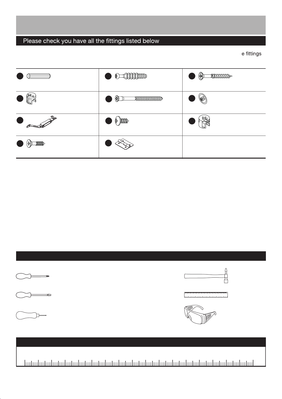
Components - Fittings
Note:
The quantities below are the correct amount to complete the assembly. In some cases mor
may be supplied than are required.
A
30mm Dowel x 2
D
12mm Locking nut x 2
G
Spring hinge x 1
J
18mm Screw x 8
B
39mm Locking pin x 6
E
65mm Screw x 12
H
14mm Screw x 4
K
Hinge x 2
C
40mm Screw x 6
F
Screw cover x 16
I
15mm Locking nut x 4
Tools required
Phillips screwdriver
(medium & large)
Flatblade screwdriver
(medium)
Bradawl
(or sharp point)
Ruler - Use this ruler to help correctly identify the screws
0 5 10 15 20 25 30 35 40 45 50 55 60 65 70 75 80 85 90 95 100
3
Small
hammer
0 1 2 3 4 5 6
110 120 130 140 1500 10 20 30 40 50 60 70 80 90 100
Ruler/tape
measure
Eye protection
(when using a
hammer or glue)
105
110 115 120 125 130 135 140 145 150 155 160 165 170
Page 5

Assembly Instructions
Step 1
Fitting dowels and
locking pins
Insert Dowels into
a:
the Bottom panel and
Back panel .
A
3
5
a:
A
3
A
5
Screw Locking pins
b:
into the Small top panel
and Front panel .
2 4
Note:
Insert locking pins
as far as shown.
Do not over tighten.
B
b:
B
B
B
B
B
2
B
B
4
4
Page 6

Assembly Instructions
Step 2
Attaching bottom panel
a:
Back panel onto the
Bottom panel .
C
5
3
a:
3
C
5
C
b:
Then carefully locate
the Front panel onto
the unit.
Insert 2 Locking nuts
into the unit.
Use a screwdriver to turn
Locking nuts clockwise
to lock.
4
D
D
b:
D
back surface
D
4
3
5
Page 7

Assembly Instructions
Step 3
Attaching side panels
and bottom support
E
C
(40mm)
H
6
a:
(65mm)
and
onto the unit.
E
H
Bottom support onto
the Right side panel
Use Screw covers to
8
6
F
cover the screw heads.
a:
4
3
E
E
Finished edge
.
8
6
E
E
F
E
E
F
F
C
F
F
F
C
F
Position the Left side
b:
panel onto the unit
using Screw
and .
Use Screw covers to
7
(40mm)
C
E
(65mm)
F
cover the screw heads.
b:
F
C
F
F
C
F
F
E
E
E
E
F
F
E
E
7
6
Page 8
Assembly Instructions
Step 4
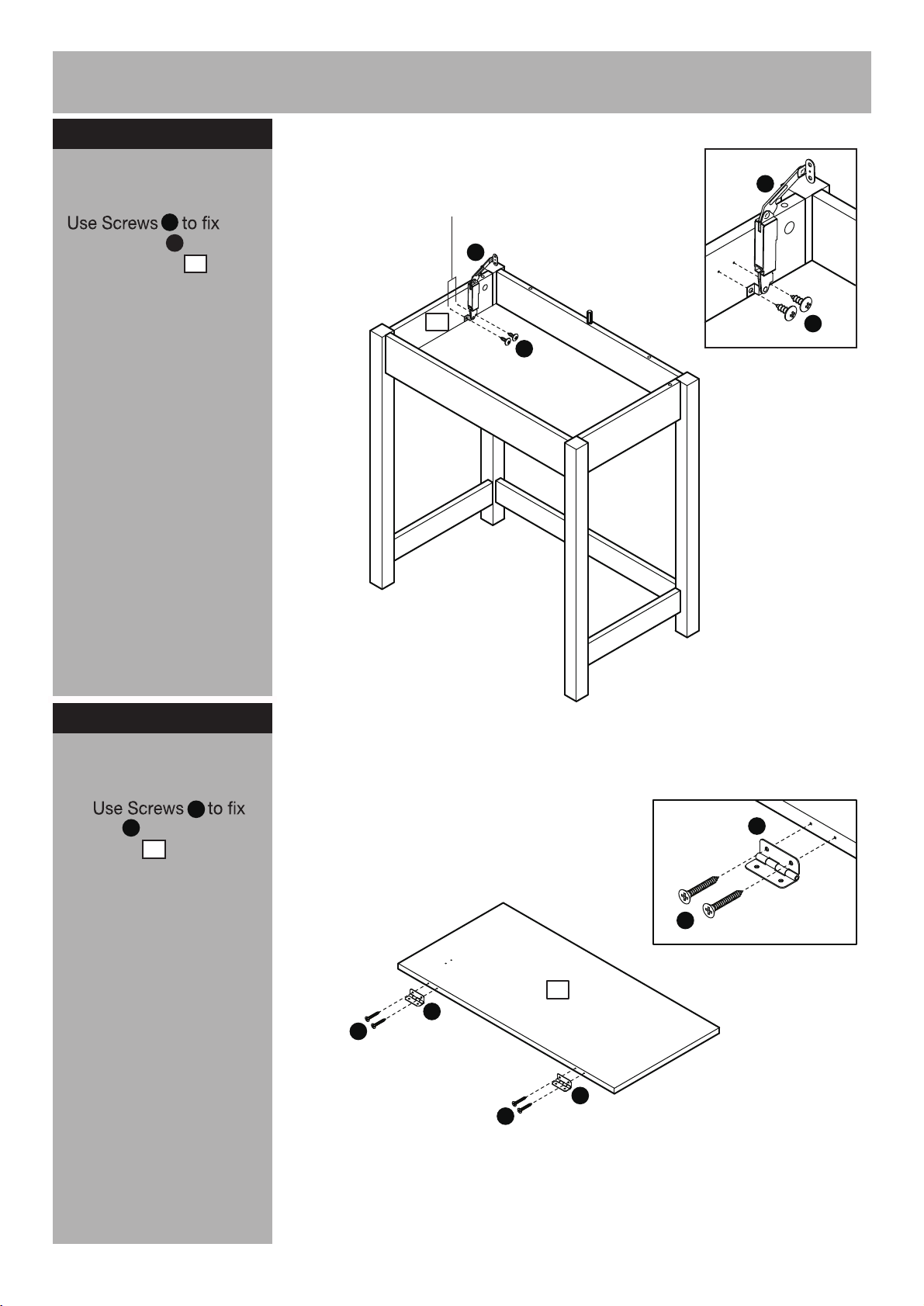
Fitting hinges
H
Spring hinge onto the
Left side panel .
G
7
Pilot holes for
guidance only
G
7
G
H
H
Step 5
Attaching top panels
a:
Hinges onto the Large
top panel .
K
J
1
a:
K
J
1
K
J
K
J
Continued on next page.
7
Page 9

Assembly Instructions
Step 5 - continued
b:
Then carefully locate
the Small top panel
2
onto the unit.
Insert 4 Locking nuts
I
into the unit.
Use a screwdriver to turn
Locking nuts clockwise
I
to lock.
b:
I
2
I
7
I
5
I
6
I
c:
Large top panel onto
J
1
the unit.
c:
1
2
2
1
J
J
J
Continued on next page.
8
Page 10

Assembly Instructions
Step 5 - continued
d:
the Spring hinge onto
the Large top panel .
H
G
1
d:
G
1
H
Step 6
Finishing the unit
Note:
It would be useful
to ask someone to help
you at the stage.
With help, place the unit in
the intended position.
Assembly is complete.
If you need help or have damaged or missing parts, call the
9
Customer Helpline: 08456 400800
 Loading...