

Page 1

AGRO-MASZ
Paweł Nowak
Strzelce Małe 78
97-515 Masłowice
Tel. +48 44 787 49 24
Fax. +48 44 787 12 02
Warranty certificate
Parts catalogue
_________________________________
SMALL ROTARY PLOUGH
POM2 POM3
Page 2

2
Address: agro-masz.eu Language version: ENGLISH
Document No: IO.POM.17.8
Created: AUGUST 2017
Copying and making excerpts only on written consent of AGRO-MASZ Paweł Nowak.
Page 3

3
Dear Customers!
Taking the opportunity to thank you for your interest in our offer and for the
purchase made, we would like to ensure that the trust placed in us becomes
the motivation for the whole team for further and more intensive work to
improve the machines belonging to the ever increasing range of products
offered by AGRO-MASZ.
In order to ensure the fullest presentation of the capabilities of our product,
we created an instruction manual, which will clearly guide you step-by-step
through the essential aspects of the technical construction of the machine
and protect against adverse effects caused by incorrect operation.
Detailed knowledge of the provisions set forth in this instruction manual,
which remains the basic piece of equipment of every machine, is necessary
for its safe use for many years.
The instruction manual should be kept in a safe place and used properly
throughout the entire period of the operation of the machine.
If it is lost or damaged, pleases order a new copy.
The new instruction manual can be ordered from the dealer of AGRO-MASZbrand the machines or directly from the manufacturer.
It is also important to note that the instruction manual should be made
available to the other user in case of sale or lending of the machine.
Every machine manufactured by AGRO-MASZ is also provided with a
warranty certificate and parts catalogue, in which all elements of equipment
of the machine are presented.
It should be kept in mind that the use of original spare parts only will ensure
the proper functionality and long service lifetime of our product. The use of
non-original and duplicated parts adversely affects its parameters.
We have put every effort to present you an easy-to-operate, solid and
reliable product, with the belief that our cooperation with you will also be
lasting and, as a result, it will allow us to develop together new solutions in
order to facilitate and increase the level of productivity in agriculture.
Thank you for choosing our product and wish all joy in your work.
Page 4

4
Page 5

5
Name:
Rotary plough.
Type/ Model:
…………………
Factory number:
…………………
Year of manufacture:
…………………
Application:
bed free ploughing of medium and large depth.
Strzelce Małe, 05.01.2015
Paweł Nowak – owner
(full name, signature of person
authorised to prepare the
declaration)
I. EC DECLARATION OF CONFORMITY FOR THE MACHINE
Manufacturer
AGRO-MASZ Paweł Nowak
Strzelce Małe 78
97-515 Masłowice
Machine
The manufacturer hereby declares that the machine, to which the declaration
relates, meets:
- all relevant provisions and regulations of Directive 2006/42/EC of the
EUROPEAN PARLIAMENT and of the COUNCIL of 17 May 2006 on the
machinery, and amending Directive 95/16/EC (Official Journal of the
European Union L157 of 09.06.2006, page 24) and Ordinance of the
Minister of Economy of 21 October 2008 on essential requirements for
the machinery (Journal of Laws, No 199, item 1228);
- requirements of harmonized standards:
• EN ISO 4254-1:2016;
• EN ISO 12100: 2012;
• EN ISO 13857: 2010;
- other standards:
• ISO 3600: 1998;
• ISO 11684: 1998;
- Regulation of the Minister of Economy of 31 December 2002 on technical
conditions applicable to vehicles and scope of the necessary equipment.
This Declaration shall become invalid if the machine is changed or
redesigned without the written consent of the manufacturer.
Name, address of person authorized to prepare the technical
documentation:
Mirosław Nowak, Strzelce Małe 78, 97-515 Masłowice
Page 6
6
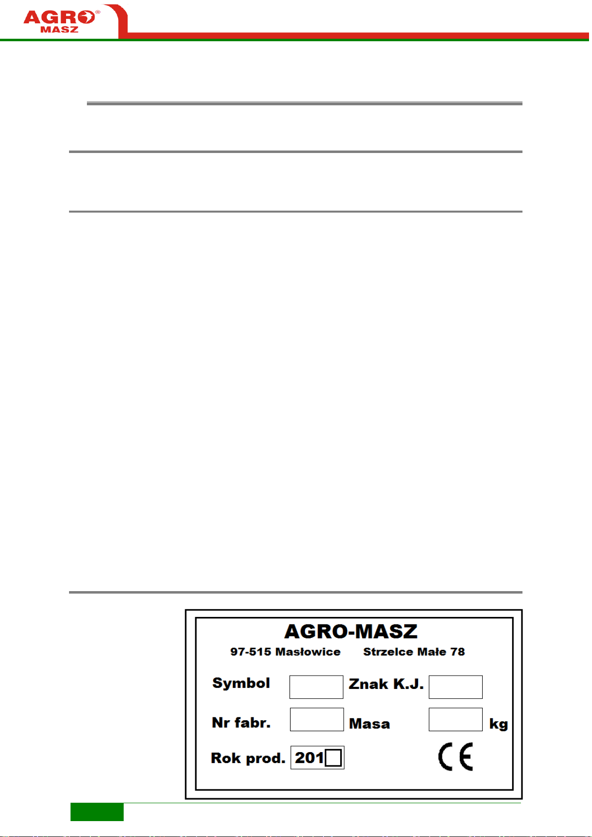
Data plate
THE MACHINE
Factory number
Symbol
Year of manufacture
Certification mark
Mass
II. THE MACHINE IDENTIFICATION
2.1. Name
Mounted rotary plough
2.2. Model symbol
POM2 – Small rotary plough, 2-furrow
POM3 – Small rotary plough, 3-furrow
2.3. Data plate
Identification data can be found on data plate attached to the machine's
frame by the three-point linkage.
Page 7

7
Page 8

8
THE MACHINE
AGRO-MASZ Paweł Nowak
Strzelce Małe 78
97-515 Masłowice
Tel. +48 44 787 49 24
Fax. +48 44 787 12 02
[email protected]
Domestic sales
Tel. +48 601 365 272
[email protected]
Export
Tel. +48 605 724 854
[email protected]
Tel. +48 661 027 679
[email protected]
Tel. +48 603 676 644
[email protected]
The purchaser (the user) of the machine should confirm to have acquainted
with warranty terms and information included in the Instruction Manual with
his/her signature.
When the machine is being sold, the seller (dealer) should enter below the
machine's symbol, factory number and year of manufacture in accordance
with the data plate and include own data.
Machine symbol ................................................................
Factory number ................................................................
Year of manufacture ................................................................
Date of sale ................................................................
Seller Address……………………………………..
Tel. / Fax……………………………………..
Purchaser (User) Address ......................................................
Tel. / Fax……………………………………..
NOTE! Remember the name and symbol of your machine. Always
use this name and symbol in contact with the seller or the manufacturer.
2.4. Manufacturer data
Page 9

9
TABLE OF
III. TABLE OF CONTENTS
DEAR CUSTOMERS! ........................................................................................................................... 3
I. EC DECLARATION OF CONFORMITY FOR THE MACHINE ............................................................ 5
MANUFACTURER .............................................................................................................................. 5
MACHINE ....................................................................................................................................... 5
II. THE MACHINE IDENTIFICATION .............................................................................................. 6
2.1. NAME ..................................................................................................................................... 6
2.2. MODEL SYMBOL ........................................................................................................................ 6
2.3. DATA PLATE .............................................................................................................................. 6
2.4. MANUFACTURER DATA ................................................................................................................ 8
III. TABLE OF CONTENTS ............................................................................................................. 9
IV. INITIAL EXPLANATIONS ....................................................................................................... 11
4.1. DIRECTIONS IN THE INSTRUCTION MANUAL ..................................................................................... 11
4.2. USER FEEDBACK ....................................................................................................................... 11
4.3. RECOMMENDATIONS AND DESCRIPTIONS ....................................................................................... 13
4.4. INTENDED USE ......................................................................................................................... 13
V. SAFETY NOTES ..................................................................................................................... 14
THE MENTIONED SAFETY REGULATIONS REFER TO THE PLOUGH. NOTWITHSTANDING, OBSERVE THE GENERAL SAFETY
AND ACCIDENT PREVENTION RULES AS WELL AS ROAD TRAFFIC REGULATIONS. ................................................ 14
5.1. GENERAL SAFETY RULES ............................................................................................................. 14
5.2. WARNING PICTOGRAMS PLACED ON THE PLOUGH ............................................................................. 16
5.3. LOCATION OF WARNING LABELS ON THE MACHINE ............................................................................ 19
5.4. OTHER RISKS ........................................................................................................................... 20
5.4.1. WIRING SYSTEM ............................................................................................................................... 20
5.4.2. HYDRAULIC SYSTEM .......................................................................................................................... 20
5.4.3. RESIDUAL ENERGY ............................................................................................................................ 21
5.4.4. FOREIGN BODIES .............................................................................................................................. 21
5.4.5. OTHER OBSTACLES............................................................................................................................ 21
5.5. OPERATOR’S OBLIGATIONS AND TRAINING...................................................................................... 22
5.5.1. OPERATOR’S OBLIGATIONS ................................................................................................................ 22
5.5.2. PERSONNEL TRAINING ....................................................................................................................... 22
5.5.3. PERSONAL PROTECTIVE EQUIPMENT.................................................................................................... 23
5.6. RISK ZONES ............................................................................................................................. 23
5.7. RESIDUAL RISK ......................................................................................................................... 24
5.7.1. DESCRIPTION OF RESIDUAL RISK .......................................................................................................... 24
5.7.2. RESIDUAL RISK ASSESSMENT ............................................................................................................... 24
5.8. STABILITY OF TRACTOR - PLOUGH ASSEMBLY ................................................................................... 25
Page 10

10
VI. GENERAL INFORMATION .................................................................................................... 27
6.1. TECHNICAL DATA FOR POM PLOUGHS ........................................................................................... 27
6.2. CONSTRUCTION OF PLOUGH ........................................................................................................ 28
6.3. CONSTRUCTIONAL CHANGES ....................................................................................................... 28
VII. MAINTENANCE AND SERVICE ............................................................................................. 29
7.1. PREPARATION OF THE TRACTOR TO WORK WITH THE PLOUGH .............................................................. 29
7.1.1. TYRES ............................................................................................................................................. 29
7.1.2. WHEEL TRACK ................................................................................................................................. 29
7.1.3. THREE-POINT LINKAGE ...................................................................................................................... 30
7.1.4. HYDRAULIC SYSTEM .......................................................................................................................... 30
7.1.5. FRONT AXLE LOAD ............................................................................................................................ 31
7.2. PREPARATION OF THE PLOUGH .................................................................................................... 31
7.2.1. MOUNTING THE PLOUGH ON THE TRACTOR .......................................................................................... 32
7.3. START OF PLOUGHING ............................................................................................................... 33
7.3.1. UPPER ATTACHMENT POINT ............................................................................................................... 33
7.3.2. SPINDLES (BOTTLE SCREWS) ............................................................................................................... 33
7.3.3. BODIES ........................................................................................................................................... 34
7.3.4. MOULDBOARDS ............................................................................................................................... 35
7.3.5. SUPPORT WHEEL .............................................................................................................................. 35
7.3.6. ADJUSTMENT OF VERTICAL TILT ........................................................................................................... 37
7.3.7. ADJUSTMENT OF HORIZONTAL TILT ...................................................................................................... 37
7.4. PLOUGH ROTATION................................................................................................................... 38
7.5. SAFETY DEVICES ....................................................................................................................... 39
VIII. TRANSPORT ...................................................................................................................... 41
8.1. DELIVERY AND UNLOADING......................................................................................................... 41
8.2. TRANSPORT – DRIVING ON PUBLIC ROADS ...................................................................................... 42
8.2.1. SPEED ............................................................................................................................................ 42
IX. MAINTENANCE ................................................................................................................... 43
9.1. LUBRICATION .......................................................................................................................... 43
9.2. BOLT TIGHTENING .................................................................................................................... 45
9.3. INSTRUCTIONS FOR PROPER OPERATION ......................................................................................... 46
9.4. DETACHMENT OF PLOUGH .......................................................................................................... 51
9.5. STORAGE ............................................................................................................................... 52
9.6. REPLACEMENT OF PARTS ............................................................................................................ 52
9.7. DEFECTS AND THEIR ELIMINATION ................................................................................................ 53
9.8. ENVIRONMENTAL PROTECTION .................................................................................................... 55
9.9. NOISE AND VIBRATIONS ............................................................................................................. 55
X. WARRANTY CERTIFICATE ..................................................................................................... 58
10.1. WARRANTY TERMS ................................................................................................................. 58
10.2. WARRANTY TABLE .................................................................................................................. 59
10.3. LIST OF SERVICE WORKS ........................................................................................................... 59
Page 11

11
XI. PARTS CATALOGUE ............................................................................................................. 61
INITIAL EXPLANATIONS
IV. INITIAL EXPLANATIONS
When you receive the machine, please make sure that there are no transport
damages, and the machine is complete!
To avoid any misunderstanding, a complaint should be filed immediately.
This instruction manual is delivered to the user of the machine at the point of
sale. Getting familiar with its provisions and guidelines gives the operator an
opportunity to conduct the safe and trouble-free operation of the machine.
Failure to observe the provisions of the instruction manual can lead to an
accident or the machine breakdown. This may result in the loss of the
guarantee and warranty rights.
The instruction manual is provided with the parts catalogue, which is to
enable the user to identify the parts and to purchase them in case of
possible damage to the machine.
Before any use, check the machine and tractor, with which it is coupled, for
work and transport safety.
The operator is responsible for his/her safety and the safety of persons that
come into contact with the plough throughout the period of use, operation
and storage.
Before using the plough, get acquainted with the instruction manual.
Special attention should be paid to the danger warning signs and safety
marks placed on the plough. They indicate important information relating to
the risk specified in the instruction manual.
4.1. Directions in the instruction manual
4.2. User feedback
The terms: “the left side" or “the right side" used in the instruction manual
mean the sides on the left and right hand of the observer facing the direction
of the machine travel, respectively.
REMEMBER! The AGRO-MASZ company assumes no responsibility for
damage caused by any failure to observe the instruction manual.
In case of any concern or doubt about maintenance and operation, consult
the authorised seller or manufacturer’s sales department.
The seller is obliged to fill in the address of the contractor of the warranty
service in the warranty certificate.
The company is developing its products and therefore reserves the right to
introduce constructional and technological changes and modifications in the
equipment.
AGRO-MASZ will be grateful for sending any comments on the use and
operation of the machine and on this instruction manual. Instruction manuals
are regularly updated, but it is your feedback that enables us to jointly create
a user-friendly instruction manual.
Office: AGRO-MASZ Paweł Nowak
Tel. +48 44 787 49 24
Fax. +48 44 787 12 02
[email protected]
Page 12

12
Page 13

13
INITIAL EXPLANATIONS
4.3. Recommendations and descriptions
The recommendations, referred to as: WARNING, ATTENTION,
REMEMBER, are used in order to underline the importance of information.
WARNING! This indicates a possibility of danger, which if not avoided, can
lead to cutting or heavier injuries to personnel operating the machine.
ATTENTION! This is used when there is a risk of damage to the machine.
REMEMBER! This is used with complementary information.
This symbol warns about the risk. Information included in the
instruction manual and marked by this symbol is particularly
important for user of the machine.
Descriptions to figures and diagrams are given next to or near them.
Procedures to be carried out by the machine's operator are given as
enumeration:
• Operation 1
• Operation 2 …
Service operations included herein, marked with this symbol
should be carried out by a specialized service.
4.4. Intended use
Mounted rotary ploughs with POM are designed for bed free ploughing of
medium and large depth on flat fields and fields with maximum inclination of
8,5o, using left and right bodies alternatively. Ploughs POM2, POM3 are
suitable for cooperation with tractors of 40 to 80 HP power. The plough is
fitted with safety devices of bodies by means of shear bolts and is intended
only for works in agriculture for cultivation of non-stony fields.
Plough should be used, operated and repaired only by personnel familiar
with its construction, operation and safety procedures.
The scope of the use compliant with its purpose also includes:
• Observance of provisions of the instruction manual (widely understood
regulations related to operation, maintenance, service, settings, repairs and
performance),
• Observance of safety regulations, in particular, warning pictograms located
on the machine and legal provisions of the country where the machine is
operated,
• Use of original spare parts only,
• Observance of maximum permissible loads of the machine (also the
recommendations of the manufacturer of the tractor, with which the machine
is aggregated).
Any use of the machine other than the above, as recommended by the
manufacturer, shall be considered as a misuse.
REMEMBER! Any arbitrary modifications introduced to the machine without
consent of the manufacturer shall exempt the manufacturer from the
responsibility for machine damages, personal injuries and other material
losses.
Page 14

14
SAFETY
V. SAFETY NOTES
assembly, get acquainted with this instruction manual, the construction of the
plough and its sub-assemblies, their functions, ranges and adjustment
method, paying special attention to information on the work safety. During
work it is too late for that!
The mentioned safety regulations refer to the plough. Notwithstanding,
observe the general safety and accident prevention rules as well as road
traffic regulations.
included in this instruction manual will allow avoiding personal accidents,
damage or premature wear of the machine.
5.1. General safety rules
REMEMBER! Before operation and use of the (tractor + plough)
WARNING! Observance of the safety rules related to the use
The below-mentioned safety regulations refer to the plough aggregated with
the tractor. Notwithstanding, always observe general occupational health
and safety rules and road traffic regulations.
• In addition to the recommendations included in this instruction manual,
follow general occupational health and safety rules as well!
• Observe warning symbols placed on the machine. Their observance is for
your own safety!
• The machine can be used only by adults who hold adequate qualifications to
drive tractors, and are familiar with instruction manuals of both the plough,
and the tractor.
• Use of the machine by minors, and children in particular, is forbidden.
• Before any start, check if the condition of the plough and tractor ensures
traffic and work safety.
• The tractor cooperating with the plough must be equipped with ballast
weights of the front axle. Balance of the tractor with the machine mounted,
its manoeuvrability and braking capacity must be maintained. Observe the
maximum permissible load per axle and transport dimensions.
• Stay of any personnel on the machine during work and transport is
forbidden. Before operation, make sure that nearby the machine there are
no bystanders. Pay special attention to children.
• Lever for the tractor hydraulic sections should be operated only from the
driver’s seat.
• Exercise particular caution when the machine is being connected to and
disconnected from the tractor. Turn the tractor's engine off, remove the
ignition key, and engage the hand brake.
• When the plough is aggregated with the tractor, raised or lowered on the
tractor’s hydraulic lift and turned on the headlands, check if there are no
bystanders, children in particular, nearby the tractor + plough assembly.
• It is forbidden to approach the plough while it is being lifted and lowered, and
turned.
Page 15

15
SAFETY
• Do not stand between the tractor and the plough while the engine is working.
• When connecting hoses to tractor's hydraulic system make sure the
hydraulic system is depressurized. Check position of control levers for the
tractor's hydraulic system.
• Appliances controlled by the hydraulic sections can be activated only when
there are no personnel within the operation area of the machine. There are
crushing and cutting places on the parts activated with the use of the other
force than their own (e.g. hydraulic system).
• Rotate the plough once the plough is lifted on the tractor's three-point
linkage.
• Raise, lower, tune and start the assembly slowly, without sharp jerks.
• It is forbidden to reverse the tractor and make turns with the lowered plough
in the working position.
• While making turns, take the far protruding elements into account, do not
use the brakes independent of the tractor.
• Check air pressure in the tractor’s tyres.
• Connect the machine to the tractor as described herein.
• The machine can be connected only to tractors of adequate power and
equipped with category 3 rear three-point linkage (in accordance with ISO
730-1:1996). Also remember to choose the tractor's class correctly to ensure
its manoeuvrability.
• In order to maintain proper tractor's manoeuvrability, the machine should be
connected to the tractor equipped with a set of front axle ballast weights.
Pressure of the tractor's front axle with the mounted plough must be at least
20% of the tractor's weight.
• Balance of the tractor with the machine mounted, its manoeuvrability and
braking capacity must be maintained. Observe the maximum permissible
load per axle and transport dimensions.
• Do not operate the plough on slopes greater than 8.5°.
• Use special, dedicated pins and cotter pins to secure connections between
the machine and the tractor. It is forbidden to use any substitute means,
such as bolts, rods, wires etc., as these can be sheared or fall out during
work or transport, and thus cause an accident or damage to the machine.
Diameter of the pins must be compliant with the machine's three-point
linkage category.
• All maintenance, repair and adjustment works should be carried out only
when the machine is lowered and the tractor's engine is turned off. Remove
the ignition key! It is forbidden to remain under the raised plough due to risk
of being crushed by machine elements.
• It is forbidden to replace working elements of the machine without proper
protection against shifting of the tractor-machine assembly and falling of the
machine.
• During repairs requiring the machine to be lifted use stable and strong
supports protecting the machine against falling. Do not use supports made
of materials that can be easily damaged (e.g. hollow tiles, bricks).
• If working units are clogged during operation, clean the machine by lifting /
lowering it few times on the tractor linkage.
• It is forbidden to leave the tractor with the machine mounted on slopes or
other sloping areas without protecting it against uncontrolled rolling. Take
care while working on the slopes.
• For operation wear working clothes and protective gloves.
• Never leave the tractor with the engine operating. Before leaving the driver’s
seat, lower the machine, turn the tractor's engine off, remove the ignition
key, and engage the hand brake.
• Do not work with the machine which is defective or incomplete. Also inspect
the hydraulic system. The cylinder, hydraulic hoses and connections must be
tight. Replace worn or defective parts immediately.
• Due to material wear and tear, flexible hydraulic hoses should be replaced
periodically, every 4 years from the date of their manufacture. The date of
manufacture, i.e. year and week number, is indicated on hydraulic hoses.
Page 16

16
SAFETY
• Exercise particular caution when driving on public roads, observe the
relevant road traffic rules and regulations. For the time of transport on the
public roads, install the following on the plough: warning signs painted in
white and red stripes, with lamps: front – white position, rear – red position
and red round reflective (warning signs can be ordered at the machine's
manufacturer on additional charge or purchased at a point of sale of
agricultural machinery) and a warning triangle for slow moving vehicles.
• For transport on public roads protect the plough against rotation by means of
a mechanical lock.
• Speed during machine transport should be adjusted to the condition of the
road surface.
• During transport, drive the tractor as close to the right side of the road as
possible.
• During manoeuvres on roads pay attention to the space around the
machine. Exercise particular caution when passing and overtaking, and on
curves (the machine is firmly connected to the tractor).
• During transport and work, it is forbidden to stand on the plough or load it
with additional ballast weights.
• Detach the plough from the tractor when the plough is supported on right
bodies on a firm and level ground, and protected with a lock, with the engine
turned off.
• During breaks in operation, the plough should be stored in a place that is
inaccessible to unauthorised personnel and animals.
• Pay particular attention when dismantling and use drawings provided in the
spare parts catalogue.
• When loading, lifting devices (e.g. forklift truck, overhead crane) can be
operated only by personnel with proper qualifications. Elements of the frame
(marked on the machine) should be used as fixing points.
5.2. Warning pictograms placed on the plough
The warning labels informing of permanent or periodical hazards are placed
by the manufacturer on the machine in easily visible locations. Do not
remove them from the machine. These labels should be replaced if worn,
damaged or illegible for other reasons.
Warning pictograms can be ordered at the manufacturer of the machine.
Each warning sign consists of two
vertically arranged fields (black figures
on a yellow background).
1 – figure on a warning triangle
background presents a risk (e.g. 1 – risk
of rolling of the machine and crushing of
the body),
2 – figure presents a way of behaviour to
avoid the risk (e.g. 2 – to avoid the risk,
secure the wheels of the machine with
wedges).
Page 17

17
SAFETY
The below section presents graphically warning signs, shows their location
on the machine, explains what type of risk they indicate and the way to keep
safety and avoid hazard.
Additionally, each sign bears a number, which refers to the number of a
warning pictogram included in the parts catalogue, which facilitates
identification of a label if damaged.
A. Risk due to non-observance of the
provisions of the instruction manual!
This risk can result in serious injuries of the
operator and bystanders.
Before using the machine, get acquainted with the
instruction manual and safety regulations included
there.
B. Risk due to uncontrolled rolling of the
machine and tractor!
This risk can result in serious injuries, even fatal, to
operator of the machine.
Before maintenance or repair works, turn off the
tractor's engine and remove the ignition key!
C. Risk of crushing of the limbs by working
elements of the machine or cutting by sharp
edges!
This risk can result in serious injuries leading to
loss of a limb, in extreme cases.
Keep a safe distance from the machine! Exercise
particular caution when replacing the working
elements!
Page 18

18
SAFETY
D. Risk of crushing of the body within the
three-point linkage operating area!
This risk can result in crushing of chest or other
part of the body, or even death of the operator.
It is forbidden to stay between the machine and
tractor when fixing the machine and starting the
lifting device!
E. Risk of crushing of the hand or fingers by
the moving parts of the machine!
This risk can result in serious injuries leading to the
loss of fingers, a hand, or even the whole arm.
Never reach into the area of moving elements of
machine (e.g. cylinders, plough rotation points,
release area of plough bodies), especially during
work of the machine or when the tractor's engine is
turned on, or the hydraulic installation is being
started!
F. Risk of crushing of the whole body due to
the machine swing while turning!
This risk can result in serious bodily injuries,
including fatal injuries.
Do not stay within the swing area of the machine
during work and transport! Keep a safe distance
from the plough when it is being swung!
G. Risk of crushing of the whole body due to
movement of an unprotected subassembly of
the machine!
This risk may cause serious injuries.
When detaching the plough from the tractor,
remember to unfold the support foot and secure it
with cotter!
Page 19

19
SAFETY
H. Marking of a place to fasten loading slings!
These are suggested places to maintain the safe
loading / unloading of the machine and its balance
while it is hanging on ropes, belts or chains.
Always take the weight of the lifted machine into account!
5.3. Location of warning labels on the machine
Page 20

20
SAFETY
5.4. Other risks
5.4.1. Wiring system
In addition to the risks defined in the section 5.2. and presented in the form
of warning pictograms placed on the machine, the other risks described by
manufacturer in this section can also appear during operation.
• Electrical devices, such as lighting system, are powered by 12V current.
• Too high or too low voltage can cause malfunction of an electronic device
or cause its damage!
• Use of non-original elements of electrical and electronic devices and
improper fuses can result in a breakdown!
• Take special care when installing electrically operated devices. Improper
connection to the tractor's battery, in extreme cases, can result in a fire or
explosion of the battery!
• When removing the electrical and electronic devices from the machine,
protect their elements (plugs, cables, etc.) properly against moisture and
atmospheric agents.
5.4.2. Hydraulic system
• Hydraulic system works under high pressure!
• Hydraulic hoses of the machine can be connected to the tractor only
when hydraulic systems, of both the machine mounted and the tractor,
are under pressure-free conditions.
• Hydraulic hoses of the machine should be connected to hydraulic
connectors of the tractor, paying attention to their correct arrangement!
Improper connection can result in a breakdown of the mounted machine
or the tractor!
• Hoses of the hydraulic system should be controlled regularly for tightness
and damages.
• Damaged hoses should be replaced immediately only with original hoses,
as recommended by the machine's manufacturer!
• Period of use (as intended) of hydraulic hoses should not be longer than
4 years.
• Do not work with the machine, in which hydraulic system is not tight!
There is a risk of a serious breakdown!
• There is a risk of being cut by the machine elements, which are moved by
means of the hydraulic system.
• During work and operation of the machine, there is a risk of cutting a skin
of face, hand, and in particular eyes caused by oil splashing!
• It is forbidden to seal hydraulic hoses manually!
• In case of skin burns or oil penetration into the body, seek medical
attention immediately!
• When checking the condition of the hydraulic hoses, use appropriate
equipment and protective clothing. It is recommended to check the
condition of hydraulic hoses by a specialized service point on a yearly
basis.
Page 21

21
SAFETY
• It is forbidden to lock hydraulic system controls in the tractor.
• Before any works on the hydraulic system:
o Lower the mounted machine,
o Remove pressure from the hydraulic system,
o Turn the tractor's engine off and engage the parking brake,
o Remove the ignition key.
5.4.3. Residual energy
WARNING! During operation of the machine keep in mind that
there is residual electric, pneumatic and mechanical energy on the machine!
Electric current for powering road lights, high-pressure oil in the hydraulic
system intended to power such sub-assemblies as rotation cylinder, ruling
cylinder and mechanical energy accumulated in the elastic parts constitute a
hazard to an inattentive operator and unauthorised personnel!
The machine's operator must be careful during work and all service and
maintenance actions carried out on the machine!
5.4.4. Foreign bodies
During operation of the machine there is a risk that the personnel remaining
nearby will be injured by stones, lumps of the soil or other foreign bodies
unexpectedly thrown by the machine and its sub-assemblies.
WARNING! During work no person is allowed to remain within the
danger zone or move near the machine, until the tractor's engine is turned
on!
5.4.5. Other obstacles
During field works there is a risk of burning or electric shock after contact with
overhead power lines or as a result of getting too near to high voltage lines.
WARNING! Observe national regulations regarding a safe
distance, within which the live overhead power lines can be approached to!
Page 22

22
SAFETY
5.5. Operator’s obligations and training
5.5.1. Operator’s obligations
The operator must:
• get acquainted with the instruction manual attached to the machine, in
particular become familiar with the safety regulations related to work, repair
and maintenance,
• take care that the instruction manual is always stored in a place ensuring its
maintenance in good condition and to make sure it is always available during
work,
• be equipped with proper protective clothes, in accordance with the
description included in 5.5.3.,
• get acquainted with the legal regulations, applicable in a specific country,
relating to the occupational safety, accident prevention and environmental
protection,
• operate the machine according to the manufacturer’s recommendations,
• use only original spare parts and do not make any modifications of the
machine without a written consent of the manufacturer.
The machine should be always stored and transported protected in order to
avoid accidents caused by contact of the children or bystanders with the
machine, untrained in their use!
5.5.2. Personnel training
The machine can be operated, to the same extent as the operator (owner),
only by personnel who are authorized and trained by the owner.
The authorized personnel (e.g. an employee) must:
• hold a driving licence compliant with requirements of regulations applicable
in a specific country,
• get acquainted with the instruction manual attached to the machine,
• observe general occupational health and safety rules,
• undergo training provided by the owner in regulations relating to work safety
(machine installation, operation and maintenance),
• get acquainted with construction and function of the machine.
The above-mentioned provisions are also applicable to any further owner of
the machine, when it is sold on the secondary market.
Page 23

23
SAFETY
5.5.3. Personal Protective Equipment
Before any service works operator of the machine must be equipped with:
• protective gloves protecting against sharp edges of the machine
elements and against a direct contact with oils and lubricants,
• clothing which do not constrain movements but, at the same time,
are tight to such extent not to be caught by any of the machine subassembly,
• protective goggles, hearing protectors and breathing protection
mask, if necessary (when strong wind is encountered during
operation or the tractor is not provided with a cab).
5.6. Risk zones
According to a general definition, a danger zone includes surroundings of
the machine, within which people can be caught. Places of risk are as
follows:
• an area between the tractor and mounted machine,
• immediate vicinity of the machine's moving elements (rotation cylinders,
ruling cylinders, springs),
• flat surfaces, such as frame,
• places within plough raising / lowering and rotating areas.
In such surroundings a person can come in contact with:
• foreign bodies ejected by the machine,
• mounted machine due to its unexpected lowering,
• the tractor-plough assembly due to its rolling or shifting when operating and
changes in its while turning or reversing, rotating,
• mounted machine due to its working elements, changing their position,
driven by mechanical, electric or hydraulic power.
When operating the machine there is a risk that parts of the body of people
present nearby will be injured! This risk can be permanent or periodically
variable. Pay attention to lumps of soil, stones and other foreign bodies
ejected by working elements of the machine in motion, and keep a safe
distance!
During operation no person is allowed to remain within reach of the tractormachine assembly, i.e. no person can be present neither directly in front of,
behind nor by the machine! It is also forbidden to move nearby and stand on
the machine during work.
People cannot stay within the risk area until:
• the tractor's engine and control units for the plough's working elements are
off (hydraulic system for rotation control, etc.),
• both the tractor and machine mounted, and its sub-assemblies are protected
against rolling and unintended motion.
WARNING! Keep a safe distance!
The risk area varies during work when the machine is running!
Page 24

24
SAFETY
5.7. Residual risk
5.7.1. Description of residual risk
5.7.2. Residual risk assessment
Residual risk mainly results from incorrect behaviour of the operator of the
plough mounted on the tractor. Reasons for such behaviour of a person
operating the machine are ignorance and inattention.
Despite the fact, that the AGRO-MASZ company – the manufacturer of the
plough POM, takes the responsibility for the design and manufacture, in
order to eliminate hazard, certain risk when operating the machine is
unavoidable.
Major source of risk follows these forbidden operations:
• stay of personnel on the plough during work and transport,
• stay of personnel between the tractor and the plough when the tractor's
engine is working,
• stay of personnel nearby the plough when it is being lifted, lowered or
rotated,
• operation of the machine when tractor engine is working,
• operation of the machine lifted on the linkage and unprotected against falling
down,
• stay of unauthorised personnel nearby the plough while operating,
• operation of the plough and the tractor in poor technical condition.
When describing residual risk, the plough shall be considered a machine,
which until the production start has been designed and manufactured in
accordance with the state of the art current as for the date of manufacture.
Apply the following recommendations:
• carefully read and follow rules herein,
• do not put hands into restricted areas,
• stay of personnel on the machine during work and transport is prohibited,
• stay of personnel between the tractor and the machine with the tractor's
engine working is prohibited,
• stay of personnel nearby the machine when it is being lifted, lowered and
rotated is prohibited,
• stay of unauthorised personnel nearby the plough while operating is
prohibited,
• operation of the plough is allowed only by the personnel who are trained and
acquainted with this instruction manual,
• performance of repair and maintenance works only by personnel who are
properly trained,
• protection of the plough against access by children, unauthorised personnel
and animals,
- elimination of all accident hazards to ensure safe use of the rotary plough
POM.
The AGRO-MASZ company, the manufacturer of the plough POM declares
that in the current state of the art it is not possible to eliminate the existing
residual risk. This risk can be reduced by using the plough POM in
accordance with the recommendations specified in this instruction manual.
Page 25
25
SAFETY
ATTENTION! Accident hazards resulting from the existing residual
risk appear in case of failure to observe the specified recommendations and
guidelines.
5.8. Stability of tractor - plough assembly
The tractor-plough assembly can lose its stability due to weight of the
mounted machine.
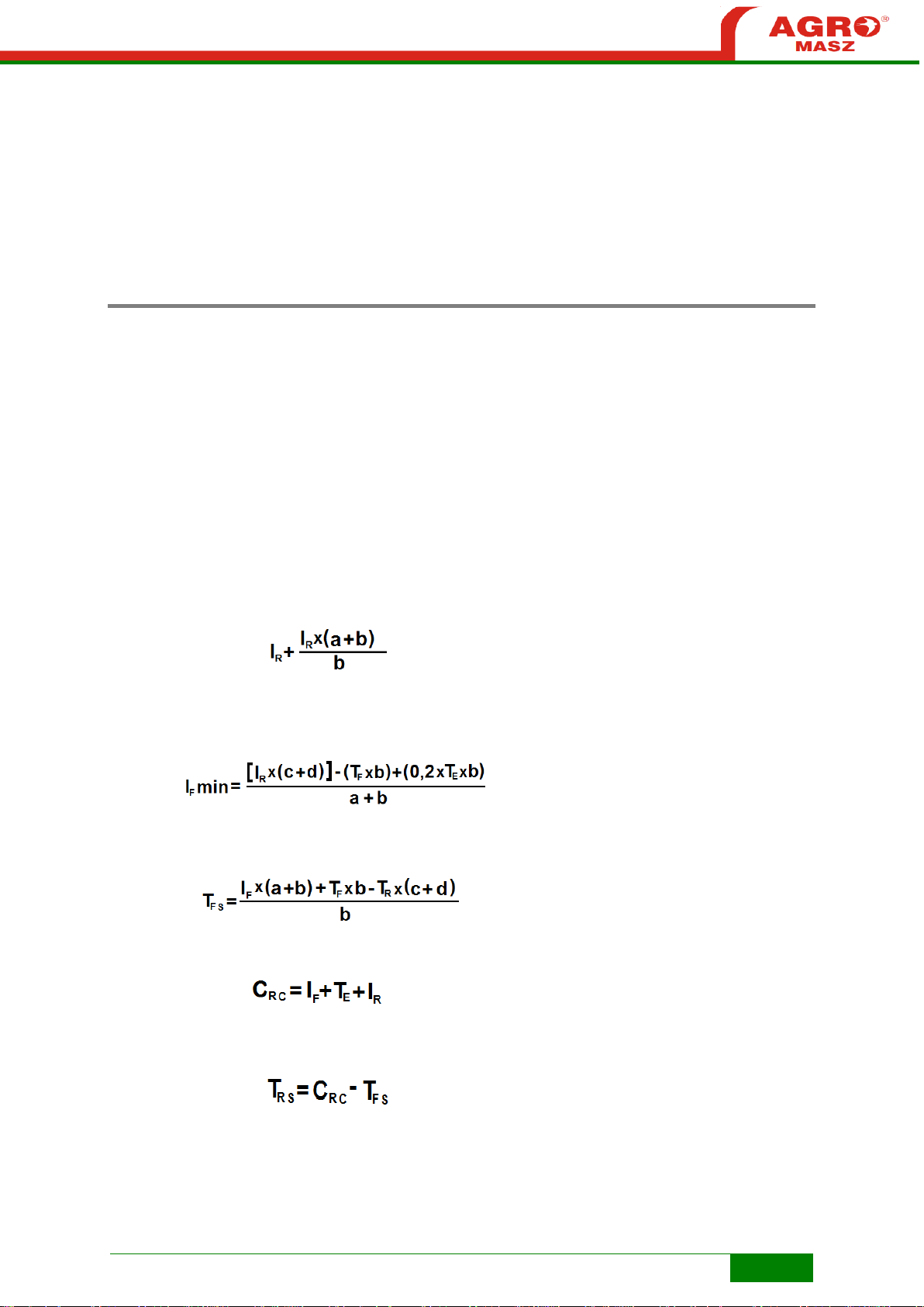
To calculate the required minimum front ballast, and also determine by how
many kilograms the load of the tractor's rear axle should be increased, in
order to ensure stability of the whole assembly, the user should know
parameters of the tractor and the plough applicable to the below
calculations.
Mounting of machines to the tractor cannot result in exceeding the maximum
permissible values, i.e. total mass of the whole tractor-plough assembly, load
of the front and rear axles, and tyre carrying capacity.
Below there are the most useful formulas to calculate maximum permissible
loads.
To calculate increase in load of the tractor's rear axle:
In order to verify the total stability, to calculate minimum mass of front ballast
weights I
the tractor overall weight, the below formula can be used:
in kg, allowing to achieve load of the front axle equal to 20% of
F,min
Formula to calculate the actual load of the front axle:
Formula to calculate the actual total weight:
Formula to calculate the actual load of the rear axle:
Page 26

26
CALCULATED
REAL VALUE
VALUE
ACCEPTABLE BY
TRACTOR
MANUFACTURER
UNIT OF
MEASURE
Minimum load of
tractor front
kg
Total weight of
tractor-plough
assembly
kg
Tractor's front axle
load
kg
Tractor's rear axle
load
kg
SAFETY
TE – tractor's overall weight (kg)
TF – front axle load of unloaded tractor (kg)
TR – rear axle load of unloaded tractor (kg)
IF – weight of front ballast weights (kg)
IR – weight of machine mounted at rear (kg)
a – distance between centre of gravity of front ballast weights and centre of
front axle (m)
b – tractor wheelbase (m)
c – distance between centre of rear axle and centre of ball joints of rear
linkage (m)
d – distance between centre of ball joints of rear linkage and centre of gravity
of mounted machine (m)
Enter calculations from formulas in the below table to compare them with
values specified by the tractor's manufacturer.
Calculated values cannot exceed the maximum permissible limits.
Page 27
27
PARAMETER
UNIT OF
MEASURE
PLOUGH POM2
PLOUGH POM3
Type mounted
mounted
Number of bodies
pcs 3 4
- distance between bodies on frame,
- height under frame,
- mouldboard type,
- ploughshare type,
- support wheel
mm
mm
850
700
semihelicoidal
zone tempered
200/60-14.5
850
700
semihelicoidal
zone tempered
200/60-14.5
Width of cut
m
0.50-0.80
0.75-1.20
Depth of cut (max)
cm
30
30
Dimensions:
- length
- width
- height
- frame profile
mm
mm
mm
mm
2400
1500
1550
100x100
3250
1700
1550
100x100
Weight
kg
510
720
Working speed
km/h
5-10
5-10
Performance
ha/h
0.25-0.40
0.40-0.60
Power demand
HP
40-60
60-80
Nominal pressure in hydraulic
system MPa
18
18
Acoustic pressure level
dB
L
pA
below 70
below 70
Skim coulter set
- -
Disk cutter for last body
- -
Openwork mouldboards
- -
Wheel shock absorber
- -
Rotation cylinder with memory
module
- -
Ruling cylinder
- -
GENERAL
VI. GENERAL INFORMATION
The plough, intended for sale, is delivered assembled by the manufacturer.
Plough bodies are equipped with sectional mouldboards, ploughshares with
bolted chisel, strips and landsides and skimmers to be mounted above
mouldboards for better coverage of plant residues. Mounting of plough body
core (frog) to plough beam enables plough body tilt angle adjustment. Before
the last body, a disk cutter is mounted for better slicing of furrow from
undisturbed soil.
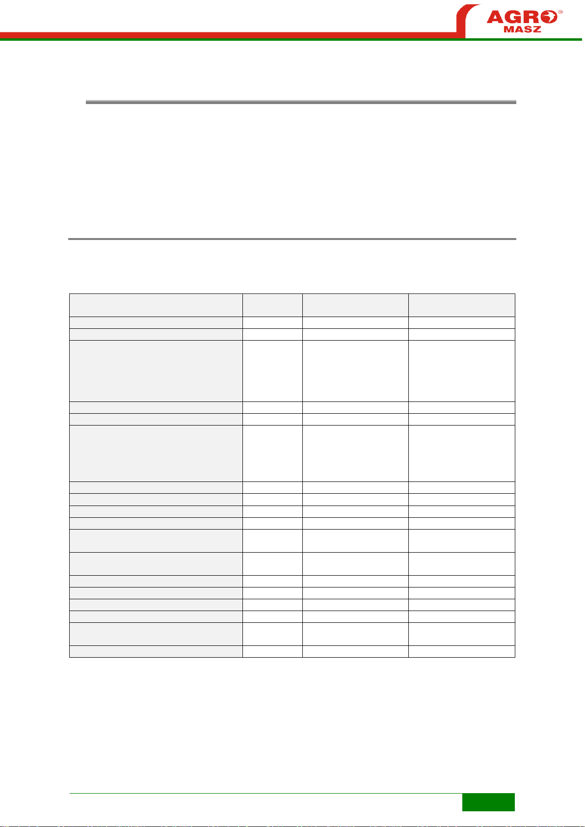
6.1. Technical data for POM ploughs
Information given in the table below is for reference only. Machine's ultimate
parameters depend on both the additional equipment and configuration.
Page 28

28
head
rotation
cylinder
firmer
support
plough
body
skim coulter
support foot
frame
ground following wheel
beam
mouldboard
firmer
holder
plough
beam
mounting
frog
blade
chisel
breast
landside
support
holder
GENERAL
6.2. Construction of plough
Overview of plough POM in version with skim coulters.
6.3. Constructional changes
Construction of a single body.
Equipment of your machine can slightly differ from equipment provided in
figures or in descriptions included in this instruction manual.
The manufacturer reserves the right to make further technical modifications
of the machine, relating to both its basic construction and additional
equipment, due to the adaptation to the ever developing technical level.
REMEMBER! All modifications and alterations of the plough made without a
written consent of the manufacturer are forbidden, or they can result in a
decrease of the machine's parameters.
Page 29

29
OPERATION
VII. MAINTENANCE AND SERVICE
Before working, it is necessary to carefully get acquainted with the
function and construction of the tractor's and plough's parts.
7.1. Preparation of the tractor to work with the plough
REMEMBER! In order to make proper adjustments of the below-described
sub-assemblies of the tractor, observe the provisions specified in the
instruction manual provided by the tractor manufacturer.
7.1.1. Tyres
In order to maintain proper service lifetime of the tyres and achieve optimum
driving properties, check and correct tyre pressure, if necessary. In
particular, it is essential to maintain the same pressure level in the tractor's
rear tyres. In difficult conditions, while observing the provisions of the
instruction manual of the tractor, it is recommended to add further ballast
weights to wheels or to fill up the tyres with a liquid. Air pressure in the tyres
must be accordingly not too high to ensure the optimum tractive force and
not too low so that the rims do not damage the tyres at the same time.
REMEMBER! In order to ensure equal working depth for the
plough, take care that pressure in the tractor's tyres is the same in right and
left tyres.
7.1.2. Wheel track
For ploughing, the wheel track is
measured as a space between
the internal surfaces of the
tractor's tyres. The distance
between the external edges of
front wheels should be equal to,
or slightly greater than, the
distance between rear wheels.
Page 30

30
OPERATION
7.1.3. Three-point linkage
The construction of the
three-point linkage is
based on the principle
that the tractor and the
mounted machine are
intended to operate as
an integral assembly.
The functionality of
such assembly depends
on a setting of the
upper link (1) and
lower links (2) adjusted
on hangers (3).
In order to facilitate the optimum arrangement of the plough, if the tractor
has several points for the attachment of the upper link, the said link should
be fixed at the top-most point.
Lower links should be set on the same height (x) by means of adjustment on
hangers. Hangers should be set so as to enable lowering of lower link to
approx. 30 cm below the plough's linkage axis and lifting of the plough onto
an adequate height for the plough's rotation and safe transport.
Regardless of whether the lower links are equipped with chains, telescopic
struts, or other side movement stabilisation system, the system should be
adjusted so that the mounted plough can move slightly sideways during work
and it does not tilt too much during transport.
7.1.4. Hydraulic system
The tractor should have 2
independent external
hydraulic sections – 2
pairs of push-in fittings
(1), i.e. two hydraulic
outputs of two-side action
to ensure plough's
rotation and two hydraulic
outputs of two-side action
for ruling cylinder
(option).
Page 31

31
OPERATION
7.1.5. Front axle load
The tractor must be
equipped with front
weights (1) to ensure
the optimum driving
properties, proper mass
distribution and equal
working depth of
ploughing.
The calculation
procedure of the
counterweight mass for
the plough as the ballast
weights mounted in front
of the tractor is discussed in the “Stability of the tractor-plough assembly”
sub-section, page 16.
ATTENTION! Attachment of the cultivating machine on the tractor
three-point linkage must not cause the maximum load parameters specified
by the tractor manufacturer to be exceeded.
7.2. Preparation of the plough
• Before work, check technical condition of the plough, and working parts and
hydraulic system in particular. Replace any damaged or worn parts causing
the plough's work quality to decrease.
• Check bolting connections, and tighten nuts, if any plays are found. After
about 3 hours of ploughing, tighten all bolts and nuts.
• Lubricate the plough in accordance with recommendations specified in the
lubrication table.
• Check the arrangement of plough bodies, and if there are no significant
differences between each particular body.
• Check whether adjustment screws turn without jamming.
• Check whether push-in fittings on the plough's hydraulic hoses match the
sockets on the tractor.
• Check the condition of hydraulic hoses (cannot be damaged) and
cleanliness of push-in fittings.
• Check the pressure in tyres of the transport wheel, which should be 350-425
kPa.
Page 32

32
OPERATION
7.2.1. Mounting the plough on the tractor
In order to attach the plough correctly and safely, the tractor should stand on
a firm and level ground.
While mounting the plough on the tractor proceed as follows:
• switch the tractor's hydraulic system into position adjustment,
• set the plough's latch bar in one of four positions and attach it on tractor's
lower links (possibly on ends of latch bar, attached on the plough, mount
ball-and-socket joints – depending what type of ends of three-point linkage
links the tractor is equipped with) and secure,
• reverse the tractor at a distance allowing connection of the latch bar to
forepart plates and the tractor's upper link to the plough's upper hanger,
• secure the suspension axle in forepart plates using pins (2) with cotters,
• attach the tractor's upper link and secure its pin. When ploughing the
attachment point for the plough's upper link should be higher than the
attachment point for the tractor's link,
• adjust the anti-roll bars of the tractor's lower links,
• connect the plough's hydraulic hoses to the tractor's external hydraulic
sections,
• unlock transport support,
• check the plough for lifting and lowering,
• perform a trial rotation of the plough to check whether during this operation
neither the support wheel nor the machine touches the ground.
WARNING! When mounting the plough on the tractor, in the three-
point linkage area, there is a risk of crushing!
Do not stand between the tractor and the machine!
Protect the tractor against rolling!
Page 33

33
OPERATION
7.3. Start of ploughing
The arrangements indicated below are essential, particularly if the plough is
operated for the very first time.
7.3.1. Upper attachment point
The plough can be
connected to the
end of the tractor's
upper link by
means of
permanent holes
(OS) or floating
holes (OP), which
additionally enable
the plough to lift
slightly whenever
a significant
resistance is
encountered.
Apart from that, it
is recommended
to use floating
holes for mounting, if the plough has 4 furrows or more.
If the upper link is to be connected to a floating hole (length-wise) on the
hanger, loosen the link so that when the plough is lowered, pin for the link is
relieved adjoining the hole's front end.
7.3.2. Spindles (bottle screws)
The internal
spindle (1) is used
for setting the
tractor-plough
hauling rope. If set
correctly, prevents
the plough's sliding,
and in turn provides
reduction in sliding
of the whole
tractor-plough
assembly, and fuel
consumption.
Page 34

34
OPERATION
When starting ploughing, in order to properly set the plough, note which
direction the tractor tends to veer to. If it turns towards the ploughed soil,
loosen the internal spindle, and if it turns towards unploughed field tighten
the internal spindle.
While external spindle (2) is used for changing of the furrow width. For
transport to the customer, it is often tightened to save space.
7.3.3. Bodies
principle as a hinge, then unscrew and put through the adjustment screw
(2), while moving the mounting with body accordingly and tighten the
screws. This needs to be done on mounting for each body in order to
maintain the same working width for all plough bodies.
An element
mounting each pair
of bodies (right and
left) to the frame
has holes for
working width
adjustment (from 1
to 4), for a body,
within approx. 32
cm and 44 cm. In
order to adjust the
setting, loosen
central screw (1),
with same working
end to the frame for all bodies should be the same. Once the adjustment is
completed, re-tighten fastening bolts (S1 and S2).
Each body has the
approach angle
adjustment. To
align all bodies and
set the same
angle, use
adjustment screw
(SR) at the back of
each body. To start
the adjustment,
loosen fastening
bolts (S1 and S2).
It is important that
the distance (x)
from the
ploughshare chisel
Page 35
35
OPERATION
However, if value of the angle of approach is too high, this can result in
undesired resistance and problems maintaining the same ploughing depth,
and finally, significant increase in fuel consumption.
When adjusting the body, do not loosen fastening bolts completely
to prevent detachment of elements of the body!
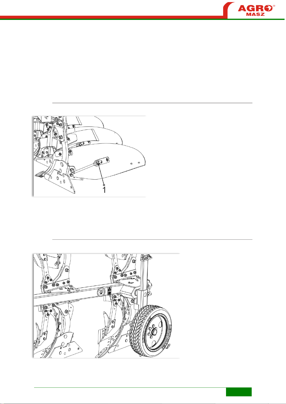
7.3.4. Mouldboards
Mouldboards are
made of tempered
steel, as they are
exposed to fast
wearing due to
contact with soil.
In order to produce
even furrows at
each passage, set
the approach angle
for all mouldboards
by means of
mouldboard
support screw (1).
In order to achieve optimum quality of the ploughing on the first use of the
plough, paint on the mouldboard, at the side which remains in contact with
soil when tilling, can be removed.
7.3.5. Support wheel
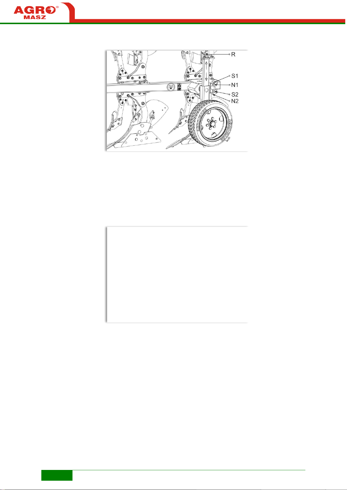
The plough is equipped with a standard universal support wheel.
Page 36
36
OPERATION
Wheel support has
a few-step vertical
adjustment,
separately for the
plough's right and
left side (screws
S1 and S2). In
connection with
the tractor's
hydraulic system,
used for lifting and
lowering of the
plough, the
adjustable support
wheel can be used
for ploughing
depth adjustment. The wheel, if properly adjusted, bears partial weight of the
plough, and thus prevents excess and uneven penetration of the plough into
soil. However, it should be noted that the plough's general weight should, as
far as possible, be borne on the tractor, so as not to cause too much of
sliding. Despite proper setting of the support wheel, the operator should
monitor the machine's working depth by means of the tractor's hydraulic
system, and take notice of variable conditions (operation on light or difficult
grounds).
The support wheel
mounting on the
frame, has
additional
adjustment (in four
positions A, B, C,
D) to align the
track of the
plough. When
setting the tractor-
plough hauling
rope, correct the
wheel
arrangement to
prevent side
sliding of the plough and damage to the whole support wheel assembly.
ATTENTION! Around the support wheel, areas of cutting and
crushing risk are present! Exercise particular caution when removing the
wheel in “transport / work” positions, and when setting the wheel working
position!
Check pressure in the plough's wheels regularly. Too high or too low
pressure during work or transport, can result in damage of the tyre, and even
the whole machine or cause an accident!
Page 37
37
OPERATION
7.3.6. Adjustment of vertical tilt
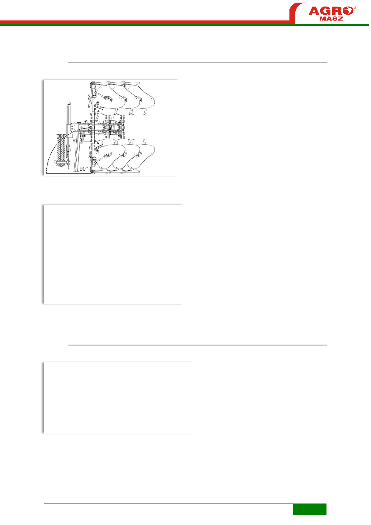
After setting of a desired
ploughing depth and
setting of the tractor so
that right or left wheels
are level on a furrow,
adjust proper working
angle for the whole
machine (vertical
adjustment). It is
desirable that in
ploughing position,
between the ground and
plough beams on the
bodies an angle of 90
(the setting can be checked by looking at the plough from its behind).
For vertical adjustment
use two adjustment
screws (L, P), located
on the plough's hanger
arms. They are used
for separate
adjustment of right and
left bodies.
In order to change the
setting of the screw for
one side of the plough,
lift the plough and
rotate it, and then
adjustment the screw,
rotate the plough again to starting point to continue the operation.
7.3.7. Adjustment of horizontal tilt
Once the first
furrow is completed,
correct the upper
link length, tilt,
furrow width, the
plough's working
depth and pressure
of the support
wheel. During work,
the plough's frame
always should be
parallel to the ground.
Page 38

38
OPERATION
7.4. Plough rotation
The plough's
rotary
mechanism is
based on twoside action
rotation
cylinder (1). The
cylinder is
mounted at the
back of hanger's
turret which
enables smooth
and safe
rotation.
External
spindle (2)
should be adjusted so that when the plough is lifted, the machine has a
sufficient clearance from the ground to ensure a collision-free full rotation,
taking into account also a change in the support wheel's position during this
procedure. If necessary, when adjustment of the spindle cannot provide a
sufficient amount of space for the plough's rotation, additionally change the
upper link's position on the hanger for higher.
Once the
plough's
rotation is
started from
the position
on right
bodies, the
two-side
action cylinder
will push the
plough to its
intermediate
position, and
then oil flow in
the cylinder is
automatically
changed,
while the plough is pushed to ploughing position on left bodies or the other
way round.
Plough in half-rotation position.
Before the plough's rotation is started, make sure within the
machine's range there are no personnel!
Page 39

39
OPERATION
7.5. Safety devices
The simplest in
use and the most
effective stone
protection device.
Each plough body
is protected with
shear bolts (s) of
adequate
hardness. These
bolts are mounted
in upper holes on
the plough beam
and holder
mounting the
whole body on the
frame. In lower
holes bolts of
greater hardness are provided, therefore once a stone is hit, an adequate
bolt is sheared, and the whole body is lifted up as on hinges.
Remember to use special bolts of adequate hardness. The
manufacturer uses shear bolts with hardness of 5.8.
Application of bolts of lower hardness, can lead to the need of replacing
them frequently, or deformation of the bolts which may damage of the
plough.
Also, use of bolts of too much hardness, can damage the machine. When
the body hits a stone, it is also possible that the bolt is not sheared, and e.g.
a ploughshare or other plough element can be subject to a damage.
Once the shear bolt is
sheared, at an adequate
point, the plough body
passes the obstacle by,
being lifted up, and then
the body gets back to the
working position.
To replace a sheared bolt:
• Carefully set the
body in its working position,
bearing in mind that it hangs on joint bolt (P), and protect it against
shifting,
• Remove remainders of the damaged bolt,
• Loosen bolt (P),
• Place and tighten new shear bolt (S),
• Tighten bolt (P).
Page 40

40
OPERATION
Keep a safe distance!
WARNING! Exercise particular caution when replacing shear bolt. Within the
area of protection of the plough body with shear bolt, there are cutting and
crushing risk points!
ATTENTION! Do not rotate the plough with released body! This may cause
damage to the machine!
During ploughing keep away from the area of plough body release!
Page 41

41
TRANSPORT
VIII. TRANSPORT
8.1. Delivery and unloading
If the machine is purchased directly from the manufacturer, the transport
conditions are determined by AGRO-MASZ, if no other arrangements are
made with the customer. The delivery time-limit is settled by the
manufacturer in consultation with the customer. The seller (manufacturer) is
responsible for the proper packaging and protection of the machine for the
time of transport. The manufacturer is also responsible for loading of the
machine for the needs of transport to the customer. However, the carrier is
responsible for the machine for the time of transport.
The plough POM is delivered assembled to the customer. Some subassemblies can be set in a transport position or disassembled. In this case
the sub-assemblies are installed by the authorised AGRO-MASZ or trading
partner’s employee at the customer’s site.
Conditions for unloading machine safely:
1. Depending on structure of a transport trailer, the plough POM can be
driven down once it's aggregated with a tractor or can be lifted by
means of a hoisting device (crane, fork-lift truck, etc.)
2. Loading and unloading of the machine and its assemblies should be
performed with a crane by personnel holding adequate qualifications.
3. The machine can be hoisted only by marked points (fixation points are
marked with decals) considering proper distribution of load and
stability of the lifted machine.
4. Check whether the hoisting device has adequate capacity and there
is no risk of the machine's falling.
5. Use only certified ropes, chains or belts of relevant strength.
6. Do not mount the machine directly onto the crane's hook and rather
use ropes, chains or belts.
7. When lifting the machine, keep ropes, chains or belts tensioned, so
as to prevent it from swinging which may cause an accident.
8. When lifting the machine with a crane, always pay attention to hoist
trajectory and remove any obstacles.
9. The whole area, where any machine's manoeuvring is to take place
and vehicle's setting location should be previously checked for any
possible "danger areas" and particularly for conductors, gas pipelines
or liquid hoses. If such “danger areas” are present, choose other
areas for manoeuvring.
10. All employees should keep proper safety distance, so in case of an
accidental falling of the machine, no person is injured.
Page 42

42
TRANSPORT
8.2. Transport – driving on public roads
Take care as the machine can swing beyond the outline of the
tractor at the corners!
Before transport, fix supports of the tractor's lower links to limit the sideways
movements of the machine!
For transport on public roads the machine is driven being lifted on the
tractor's three-point linkage.
For driving on public roads, according to valid regulations, the machine
should be equipped with lighting and warning plates.
After leaving the field, and before driving onto roads, clean the machine of
the soil.
8.2.1. Speed
Always keep in mind that the tractor's rear axle is significantly
loaded and its front section must be additionally loaded to keep proper
manoeuvrability of the assembly.
REMEMBER! Before work in the field, remember to remove lighting and
warning plates to prevent their damage.
Always adjust the speed to the road conditions and observe road traffic
regulations. The maximum permissible speed during transport of the plough
equipped with a universal support wheel on the roads in all conditions is 25
km/h.
Page 43

43
COMPONENT
NAME
NUMBER OF
LUBRICATION
POINTS
TYPE OF
GREASE
LUBRICATION
FREQUENCY
1, 2
Rotation bearing
1
ŁT-41
20h of operation
3
Mounting of
ground following
wheel bracket
1
ŁT-41
20h of operation
4, 5
Pins of framehanger joint
2
ŁT-41
20h of operation
6
Bottle screws
2
ŁT-41
Once a year
7
Tilt cylinder
joints
2
ŁT-41
50h of operation
MAINTENANCE
IX. MAINTENANCE
The machine can be repaired and serviced only by personnel with
proper knowledge and being familiar with the possible risk and instruction
manual!
To keep the plough in the best technical condition and its optimum service
lifetime, maintain its elements in accordance with the below-mentioned
schedule.
Apart from elements subject to regular lubrication, to keep the machine's
functionality, it is necessary to inspect:
• tightening of bolts and nuts connecting elements of the plough,
• technical condition of hydraulic hoses which, if apparent mechanical
damages or rubber porosity is found, should be replaced,
ATTENTION! It is forbidden to work under the raised plough
without its additional protection!
9.1. Lubrication
Proper care of the lubricated elements of the plough will prevent the
penetration of dirt or water into places between movable parts of the
machine, and as a consequence, will protect against its premature wear.
Lubricate until grease gets out from the lubrication point. Remove the excess
with a cloth to prevent accumulation of dirt on the grease.
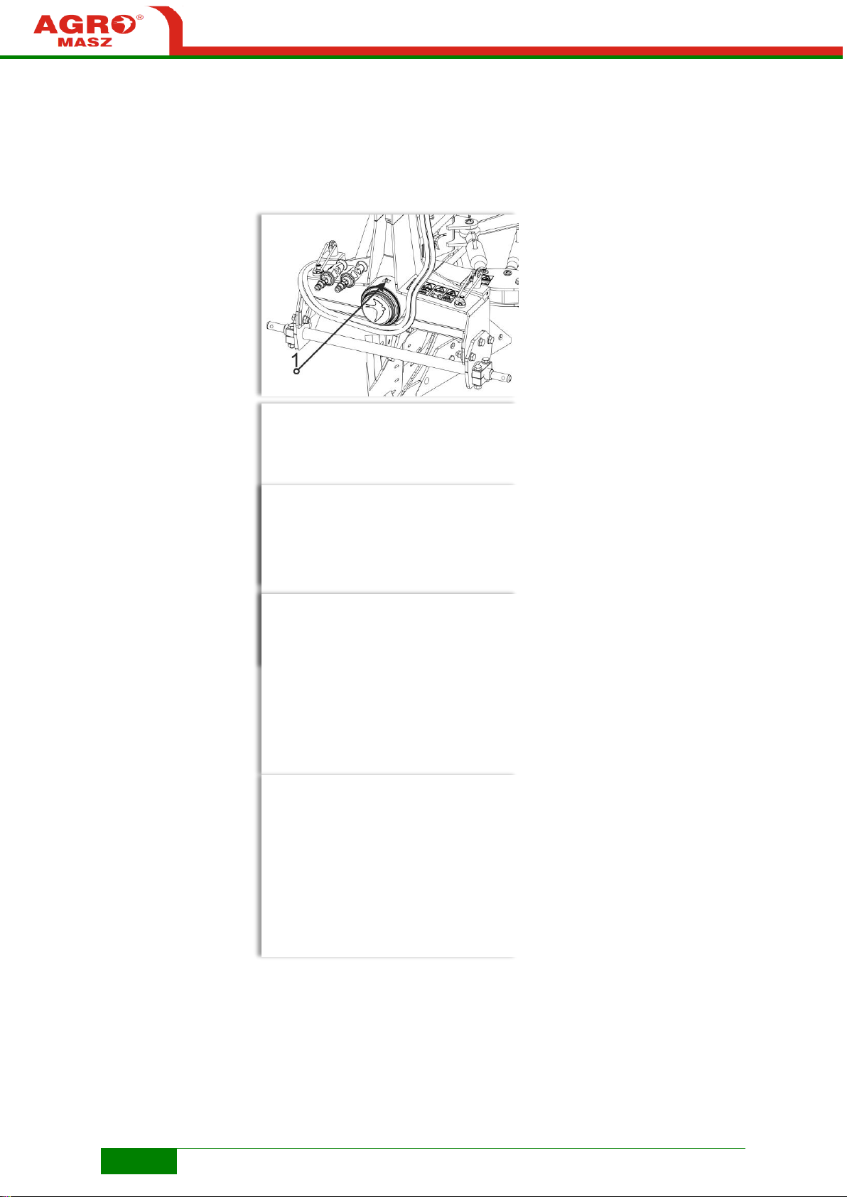
REMEMBER! Make sure that before the first use the rotation bearing is
greased abundantly (approx. 3L).
LUBRICATION PLAN
Page 44
44
MAINTENANCE
Rotation bearing
Mounting of ground following
wheel bracket
Pins of frame-hanger joint
Pins of frame-hanger joint
Page 45

45
Bottle screws
Tilt cylinder joints
REMEMBER! For maintenance, use adequate enriched grease! Use of a
grease of inadequate parameters can result in the faster wear of the plough
parts or their breakdown!
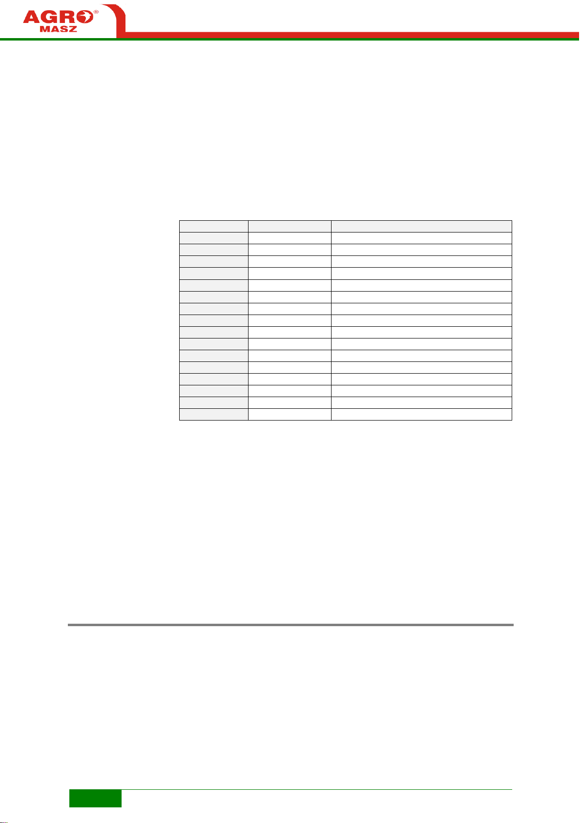
9.2. Bolt tightening
The machine is provided with bolts with hardness grade of 8.8, 10.9 and
12.9. The below table is intended to indicate the torque measured in Nm that
should be applied to bolts of particular sizes and hardness grades for
different sub-assemblies of the machine in order to ensure its proper
operation and protect against part loosening and breakdown. The table
includes most types of the bolts used in the machine.
REMEMBER! Suggested values provided in the table are given for reference
only.
Bolts and nuts can be oiled so as to provide their easier tightening (applying
less torque).
Page 46
46
SIZE
HARDNESS
TIGHTENING TORQUE (Nm)
M12
8.8
80-85
M14
8.8
137-145
M16
8.8
195-207
M20
8.8
380-410
M24
8.8
658-672
M30
8.8
1290-1332
M12
10.9
102-120
M14
10.9
178-198
M16
10.9
276-300
M20
10.9
542-590
M24
10.9
933-1005
M30
10.9
1820-1910
M12
12.9
135-145
M16
12.9
332-360
M20
12.9
648-712
M24
12.9
1105-1240
MAINTENANCE
REMEMBER! Damaged bolts should be replaced with new ones of the same
quality.
Control the tightening torque of bolts during operation!
Tighten all bolts and nuts after the first day of operation!
Tighten all bolts and nuts after the end of the working season!
ATTENTION! It is forbidden to use bolts with the parameters other
than applied by the manufacturer!
9.3. Instructions for proper operation
Even if settings of each particular element of the plough are correct, this will
not ensure a high quality of ploughing unless the whole machine is checked
for vertical and horizontal setting.
Page 47

47
Correct vertical setting of the plough.
Page 48
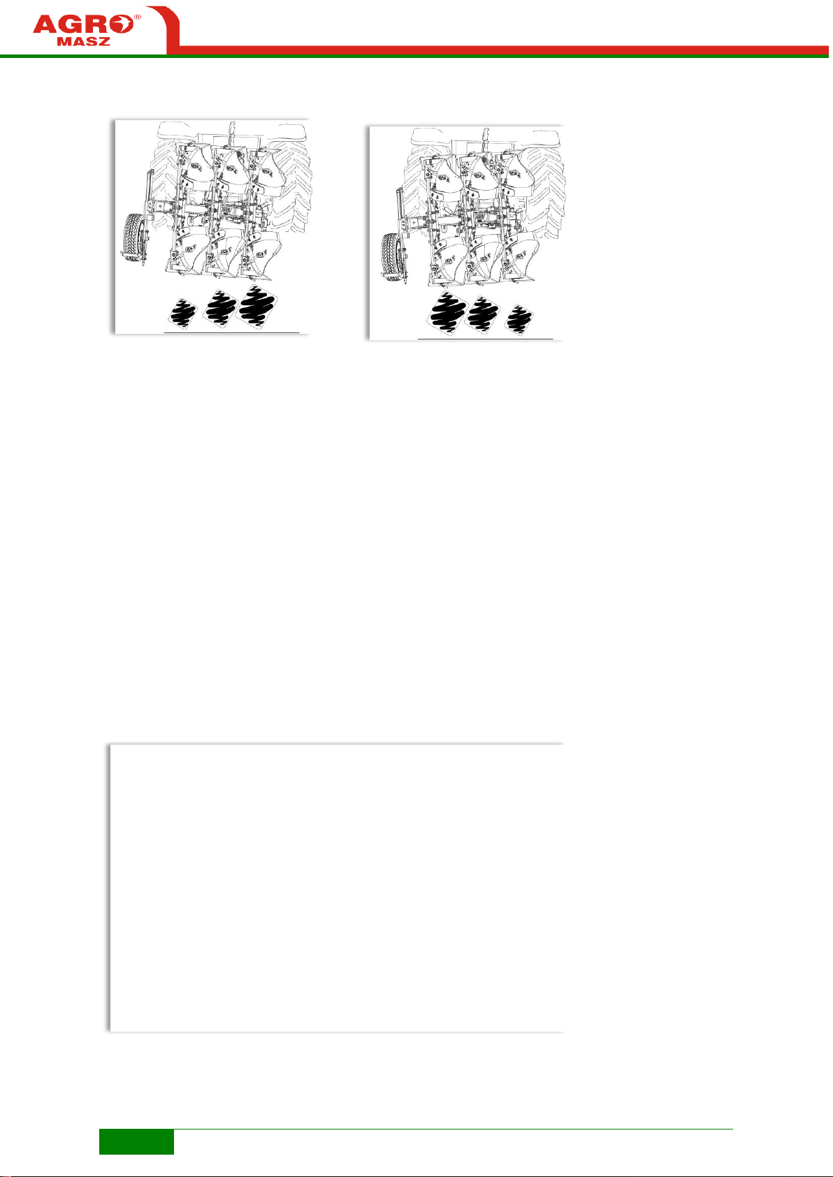
48
OPERATION
Incorrect vertical settings of the plough.
As far as the quality of work is concerned, it is important to have the depth
correctly set. Maximum working depth should not be greater than 2/3 of the
furrow width, which in normal soil conditions will allow to produce furrows
which are properly turned over and balanced.
Page 49

49
Correct horizontal setting of the plough.
Incorrect horizontal setting of the machine.
Page 50

50
OPERATION
Ploughing quality is significantly influenced by an apparently obvious matter
of turning on headlands. It is recommended to take turns using either of two
methods:
• Turn by 360o – when approaching the edge of the field, start the
plough lifting function at the same time turning maximally to the
ploughed part of the field, and shortly after that smoothly turn the
steering wheel maximally to the opposite direction, and then
approach the unploughed part again, turn and lower the plough.
• Three-point turn – lift the plough on headland, turning accordingly
towards the ploughed field, drive the tractor back to the unploughed
part and turn smoothly to get near and lower the plough.
Adjust working speed according to soil conditions, stony fields in particular,
cultivation of which, with too high working speed, may result in a major
damage to the machine.
Always try to drive as straight as possible. Careless driving (uneven
furrows), apart from deterioration in quality of ploughing, as consequence will
result in sudden load of the tractor and progressive increase in fuel
consumption.
It is not possible to carry out ploughing using only right or left bodies. Always
use left and right bodies alternatively. Bodies at both sides should wear
evenly, which in turn will produce a uniform furrow at both sides.
Always mark headlands (across the field, in particular), while using the last
plough body which will facilitate loosening of the tractor's upper link. A
headland should be of an adequate width, including length of the tractorplough assembly.
Page 51

51
MAINTENANCE
9.4. Detachment of plough
The plough always should be parked on a firm and level ground.
To safely detach the plough from the tractor:
• turn the plough to working position and lower it so it is supported with right
bodies on the ground,
• turn the tractor's engine off and remove the ignition key,
• set lever for hydraulic connector control valve in neutral position (to remove
pressure from the hoses) and disconnect the plough's hydraulic hoses,
• detach the upper link of the three-point linkage from the plough's hanger,
• unlock and lower support foot (1) of the plough,
• remove lower links from the plough's latch bar.
Page 52

52
MAINTENANCE
9.5. Storage
The machine should be cleaned on regular basis, taking particular care after
the end of the working season for a storing period between the working
seasons, which will affect its service lifetime. The plough can be cleaned by
means of compressed air or a pressure washer. However, the water jet
should not be directly pointed to the lubrication places and bearings.
The elements of the machine indicated in the lubrication table also should be
lubricated before every working season, after its end, as well as after every
washing of the machine (in particular after the use of pressure washer).
The preserved machine should be parked and stored on a firm and level
ground, with unfolded and secured support foot (the plough should not be
supported on the wheel), shielded from direct impact of weather conditions
(sun, rain, snow) which will protect metal elements without paint against rust,
and rubber elements against damage.
ATTENTION! Make sure children and animals have no access to
the machine.
Additionally, surfaces which lose paint coating due to work in contact with
soil, should be preserved with oil.
9.6. Replacement of parts
Parts, technical condition of which shows wear, should be replaced
immediately, so as to prevent other sub-assemblies against wear, which in
turn could cause deterioration in quality of work performed by the machine.
To maintain functions of the plough, it is essential to use original spare parts
only.
Before replacement of any parts, the plough should be set in transport
position and protected against falling down by means of an adequately
strong and stable support (e.g. a thick metal support or a wooden beam). It
is also necessary to turn off the tractor engine, engage the parking brake
and protect the tractor wheels with additional supports. It is recommended to
clean the area of the machine, maintenance of which is to be performed.
Only after it is certain that the plough is stable, replacement of worn or
damaged parts can be performed.
Elements of the plough, working in a direct contact with the soil, i.e.
ploughshares, ploughshare chisels, mouldboards, and other parts of plough
bodies and shear bolts, are exposed to the fastest wear.
Chisels (ploughshare blades) are elements the construction of which
enables reversing them, if one end is worn significantly.
Page 53

53
MALFUNCTION
POSSIBLE CAUSE
REPAIR ACTION
Oil leaks from
hydraulic hose fitting
Soiling of seal area
Thoroughly clean
internal and external
side of the plough's
and the tractor's
fittings
Damaged seals on
quick couplings
Replace quick
coupling end
Loose nut connecting
push-in fitting to
hydraulic hose
Tighten quick coupling
nut
Tractor tends to turn to
one side
Uneven setting of
protective means to
stabilise tractor lower
links
Adjust setting of link
stabilisers
Incorrectly adjusted
plough
Correct settings of
particular elements of
plough (refer to
“Maintenance and
service”)
MAINTENANCE
Ploughshares should be replaced in good time before section where the
chisel is bolted is affected by wear. However a ploughshare can be
recovered, if its wear allows for this.
Mouldboards should be replaced together with supports, if there is a
deterioration in dumping of a produced furrow, or eventually, if the element
starts to get deformed.
It is forbidden to perform maintenance works of the plough without
providing an additional protection against falling down, shifting or releasing
of its parts!
Use protective clothing (gloves, goggles, etc.) in order to protect against
sharp parts of the machine. Working elements in contact with the soil can be
particularly sharp. Their improper operation can result in personal injury!
Protect skin against direct contact with greases and oils!
Prevent penetration of lubricants and oils into the soil!
Use only tools in proper technical condition!
9.7. Defects and their elimination
The below table presents the possible defects during operation and most
often incorrect arrangements of the machine, causing unintended faster
wear of the plough and the tractor.
Page 54

54
MALFUNCTION
POSSIBLE CAUSE
REPAIR ACTION
Tractor front section is
lifted
Improper additional
loading of tractor front
section in relation to
plough's weight
Mount more front axis
weights on tractor
Fill front tyres with
liquid (if provided by
the tractor
manufacturer)
Plough does not
penetrate into soil
Upper link on tractor's
three-point linkage is
too loose
Tighten upper link to
shorten
Link is mounted to
high on plough's turret
Re-attach upper link
on plough's lower
attachment hole
Plough “jumps”
causing uneven
passage
Plough's weight is
distributed in excess
on support wheel
Adjust support wheel
setting to distribute
part of plough's weight
onto tractor
Plough body protecting
bolt (peg) is sheared
too often
Use of bolt with
inadequate diameter
or hardness
Mount original bolts
with adequate
hardness
Uneven ploughing on
the right and on the left
Improper vertical
setting of the plough
Adjust setting screws
(see “Adjustment of
vertical tilt”)
Different settings of
approach angle for
right and left
mouldboards
Adjust mouldboards
position
Uneven pressure in
tractor's rear tyres
Adjust pressure
according to the tractor
manufacturer's
instructions
Furrows are not turned
over completely
Set furrow width is too
narrow related to
ploughing depth
Increase furrow width
(refer to “Plough
bodies – Fig. Change
of furrow width”)
Furrows are uneven
on the same passage
Mouldboards are not
set parallel
Adjust mouldboards to
be parallel
Skim coulters are set
for various depths
(plough optional
version)
Adjust skim coulters
higher / lower, all at
equal height
Improperly adjusted
disk cutters (plough
optional version)
Adjust furrow width
and cutter setting
MAINTENANCE
Page 55

55
MAINTENANCE
9.8. Environmental protection
When the machine is significantly worn, as a result of the expiry of its service
lifetime, it should be utilised by a specialist company, in accordance with the
applicable environmental protection regulations.
Worn and damaged parts of the machine, replaced with the new ones,
should be dealt in a special way, as well. Such parts should be stored on the
farm in a specially isolated place, protected against access of people and
animals, and periodically delivered to the collection points (metal scrap
points).
Plastic parts (hydraulic hoses, tyres) should be delivered to separate
collection points for recycling purposes.
9.9. Noise and vibrations
The machine does not pose a health risk to the operator, because the noise
level / level of emitted acoustic pressure at the workplace, corrected by the
characteristics A, does not exceed 70dB (A).
There is no vibration hazard while using the plough, either.
The operator's workplace is the tractor's cabin, appropriately and
ergonomically shaped and cushioned.
Page 56

56
NOTEBOOK
NOTES
Page 57

57
INDEX
INDEX
Page 58

58
WARRANTY
X. WARRANTY CERTIFICATE
Any defects under warranty should be notified directly to the manufacturer at
+48 661 076 457.
For proper warranty service, in addition to the afore-mentioned notification,
the machine's user should submit photographs of the machine showing the
defect at: [email protected].
10.1. Warranty terms
1) The “user”, as referred herein, means any natural or legal person purchasing
agricultural equipment; the “seller” – a trade unit delivering equipment to the
user, the manufacturer – a maker of agricultural equipment.
2) Before work, the user should carefully get acquainted with this instruction
manual in order to avoid unnecessary breakdowns, as failure to observe
rules for proper operation results in reduction of the machine's efficiency and
loss of warranty rights.
3) The manufacturer guarantees its products against faults in materials or
production.
4) Faults or damages to the plough found within 12 months from the date of
purchase shall be removed free of charge at the Purchaser.
5) Faults or damages should be submitted personally, in writing or by
telephone. Warranty repairs are performed by the manufacturer.
6) If it is necessary to perform 4 warranty repairs within the warranty period,
and the product still fails to function properly, the purchaser is entitled to
have the product replaced with a new defect-free one or have the money
returned.
7) Upon completion of the repair, the manufacturer must submit a warranty
claim within 14 days.
8) The purchaser bears costs of technical evaluation – when the manufacturer
finds that the claimed product is defect-free and it is confirmed by an expert
opinion.
9) The manufacturer has the right to cancel the warranty, if within the warranty
period the machine was used not as intended, and any unauthorised
technical modifications or repairs were carried out.
10) The warranty does not cover the removal of damages caused by the user,
• removal of damages due to modifications or alterations of the product not
agreed with the manufacturer (design modifications),
• removal of damages caused by random or other events, for which the
manufacturer shall not be held responsible,
• removal of damages caused due to the use of the machine not as intended
or against provisions of the instruction manual,
• replacement of ploughshares, ploughshare chisels, breasts and
mouldboards, shear bolts, landsides, and other parts, wear and tear of which
can occur before the end of warranty period.
The above warranty terms are valid in Poland and apply to the purchase of
the machine by the user residing in Poland.
Page 59

59
MACHINE INFORMATION
Plough symbol
Factory number
Date of sale
Manufacturer's
signature and
stamp
Seller's signature
and stamp
N
o
.
SCOPE OF REPAIRS
DATE, REPAIR
CONTRACTOR'S
SIGNATURE STAMP
1
2
WARRANTY
10.2. Warranty table
ATTENTION! When the product is purchased, request the seller to fill in
exactly the warranty certificate, specifying the date and place of sale and
have the data confirmed with the seller’s stamp and signature.
Otherwise the purchaser may lose his / her warranty rights. The warranty
certificate, if not filled in, filled in illegibly or corrected, is invalid.
10.3. List of service works
Page 60

60
3
SCOPE OF REPAIRS
DATE, REPAIR
CONTRACTOR'S
SIGNATURE STAMP
4
5
WARRANTY
Page 61

61
PARTS
XI. PARTS CATALOGUE
Spare parts can be purchased at the point where the machine was sold, or at the machine's
manufacturer.
When ordering spare parts include the following data:
• machine symbol, year of manufacture, factory number (see data plate),
• catalogue part designation,
• reference number,
• quantity,
• exact address and phone number of orderer.
Using the catalogue, find the machine's part to be ordered in the figure and determine its
designation and catalogue number specified in the table of contents and corresponding reference
number.
Page 62

62
Fig. R1
PLM0015 Plough POM 3+1 (pictograms)
LIST OF PARTS
NO.
QUANTITY
REFERENCE NUMBER
DESCRIPTION
1 1 EW00060
Warning pictogram - Read the Manual
2 1 EW00061
Warning pictogram - Stop the engine before any
servicing
3 1 EW00063
Warning pictogram - Risk of crushing of the
limbs by working elements of the machine or
cutting by sharp edges
4 1 EW00068
Warning pictogram - Stay of personnel between
the tractor and the machine mounted is
prohibited
5 1 EW00260
Warning pictogram - Risk of crushing of the
body by structural elements. Mount the
support.
6 1 EW00062
Warning pictogram - Do not reach into crushing
area
7 1 EW00067
Warning pictogram - Stay of personnel in a close
proximity to the machine mounted is prohibited
8 1 PL01857
Sticker Speed limit
9 2 EW00066
Information pictogram - Sling fixation point
PARTS
Page 63

63
Fig. R2
PLM0015 Plough POM 3+1
LIST OF PARTS
NO.
QUANTITY
REFERENCE NUMBER
DESCRIPTION
1 1 PL01321
Hitch with turntable POM
2 3 PL00794
Link pin dia25.5xL105
3 3 EL00044
Spring peg dia10xL45
4 1 PL01485
Connector
5 2 PL01487
Rotary plough POM body with mounting
6 1 PL01488
Rotary plough POM body with mounting
7 2 EW00194
Rubber plug 100x100
8 1 PL01525
Ground-following wheel mechanism side frame
100x100
9 1 PL01540
Bottle screw - ruling POM2
10 1 PL00789
Link 470mm
11 1 PL01544
Foot
12 1 PL01739
Hinge POM complete
13 1 PL01774-02
Frame POM3
14 1 EW00004
Cotter with clip dia10
15 1 EW00391
Plastic plug 50x50
Page 64
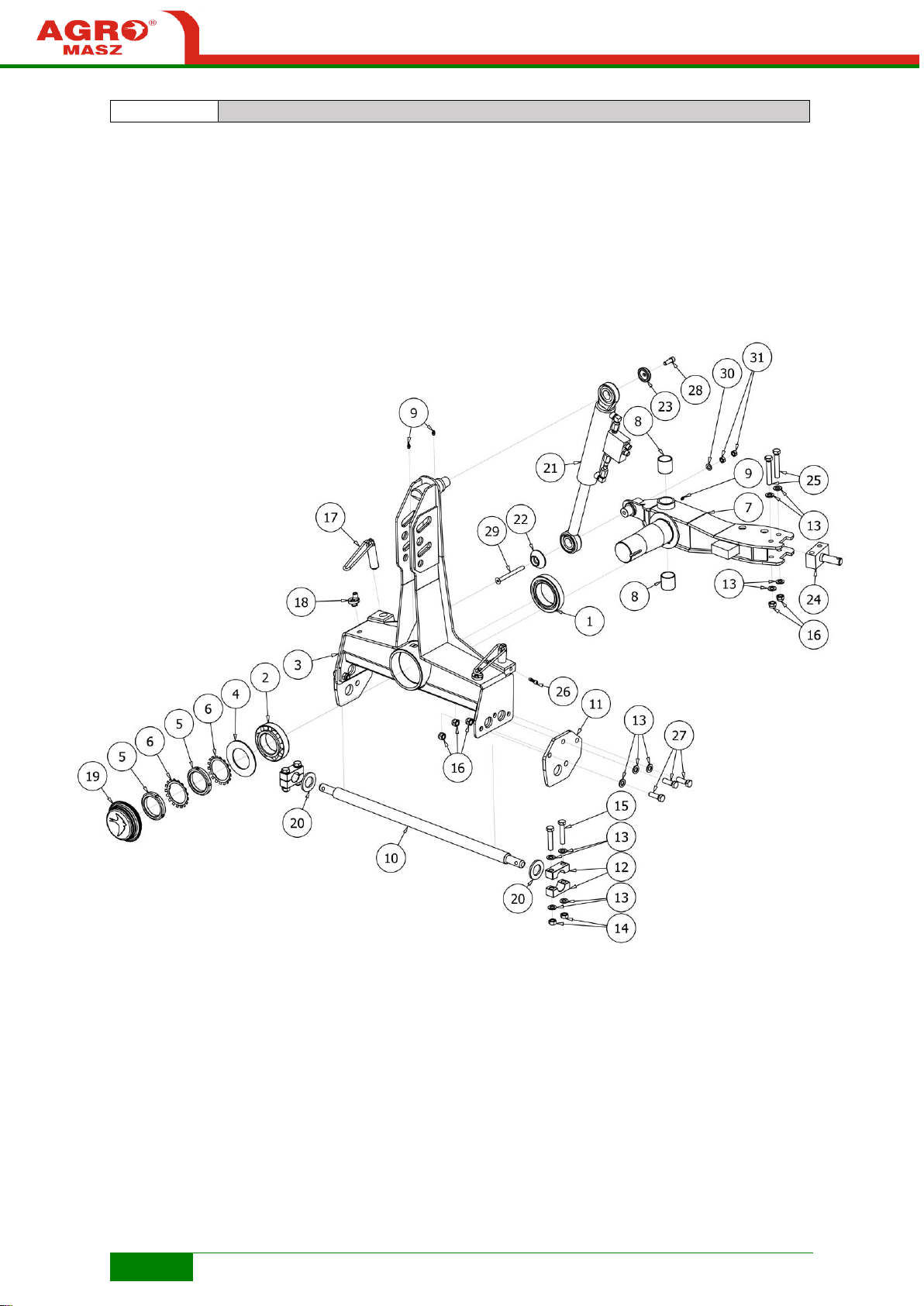
64
Fig. R3
PL01321 Hitch with turntable POM
Page 65
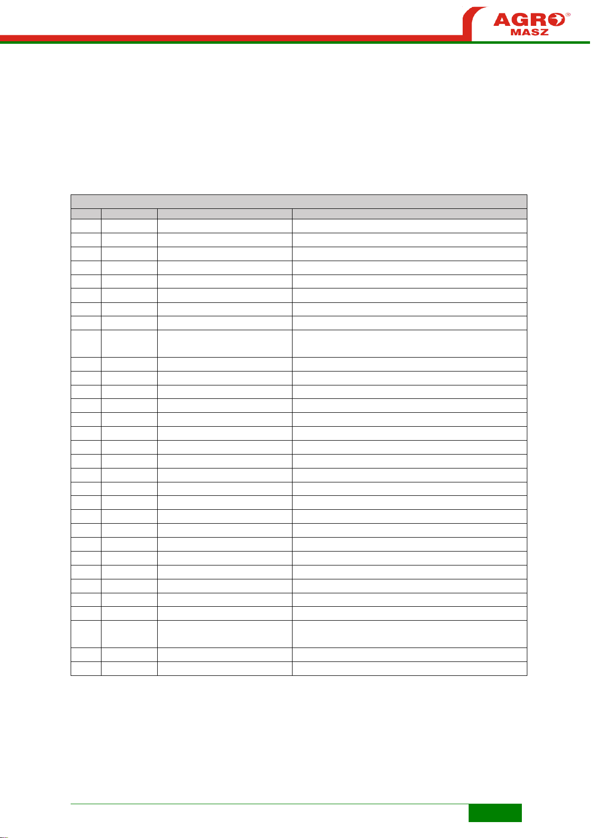
65
LIST OF PARTS
NO.
QUANTITY
REFERENCE NUMBER
DESCRIPTION
1 1 EL00060
Tapered roller bearing 32018
2 1 EL00061
Tapered roller bearing 32216
3 1 PL01324
Hitch POM
4 1 PL01325
Dust protection
5 2 EL00058
Bearing nut KM16
6 2 EL00059
Bearing washer MB16
7 1 PL01327
Turntable POM
8 2 PL01351
Sliding sleeve 45x50
9 3 EL00020
Grease nipple Type A DIN 71412 - AM8 x 1 conical
short
10 1 PL01345
Spindle 40 dia36 POM
11 2 PL01342
Adapter hitch
12 4 PL01498
Spindle lock POM
13
18
P16/O
Flat washer M16 zinc plated
14 4 N16/10/0
Flat washer M16 10 zinc plated
15 4 S16x80/8.8/O
Bolt M16x80 8.8 zinc-plated
16 8 NS16/O
Locknut M16 8 zinc plated
17 2 PL02416
Rotation adjustment with knob
18 2 PL01267
Spring lock
19 1 PL01746
Turntable plug POM
20 2 BT02026
Washer M41 zinc plated
21 1 PL01406
Hydraulic cylinder SMT2AM.63x36x240 + valve
22 1 PL00839
Lock - socket dia35
23 1 PL00226
Cylinder protection upper
24 1 PL00040
Foot holder
25 2 S16x100/8.8/O
Bolt M16x100 8.8 zinc-plated
26 2 PL01760
Rotation angle adjustment lock
27 6 S16x50/8.8/O
Bolt M16x50 8.8 zinc-plated
28 1 SI12x35/8.8/O
Hexagon socket bolt M12x35 8.8 zinc plated
29 1 SW12x140/8.8/O
Countersunk bolt with hexagonal socket M12x140
10.9
30 1 P12/O
Flat washer M12 zinc plated
31 2 N12/8.8/O
Flat washer M12 8.8 zinc plated
Page 66
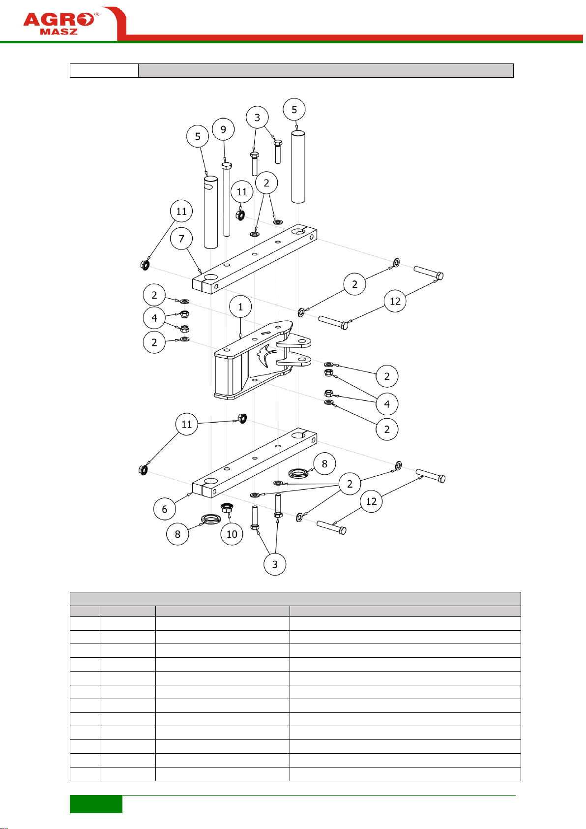
66
Fig. R4
PL01739 Hinge POM complete
LIST OF PARTS
NO.
QUANTITY
REFERENCE NUMBER
DESCRIPTION
1 1 PL01734
POM hinge reinforcement
2
12
P16/O
Flat washer M16 zinc plated
3 4 S16x70/8.8/O
Bolt M16x70 8.8 zinc-plated
4 4 NS16/O
Locknut M16 8 zinc plated
5 2 PL01745
Pin dia45
6 1 PL01743
Hinge flat POM
7 1 PL01732
Hinge flat POM
8 2 EL00043
Bearing nut KM09
9 1 S20x1.5x250/10.9/O
Bolt M20x1.5x250 10.9 zinc plated
10 1 NK20x1.5/10/O
Flange nut M20x1.5 10 zinc plated
11 4 NK16x1.5/10/O
Flange nut M16x1.5 10 zinc plated
12 4 S16x1.5x100/10.9/O
Bolt M16x1.5x100 10.9 zinc plated
Page 67
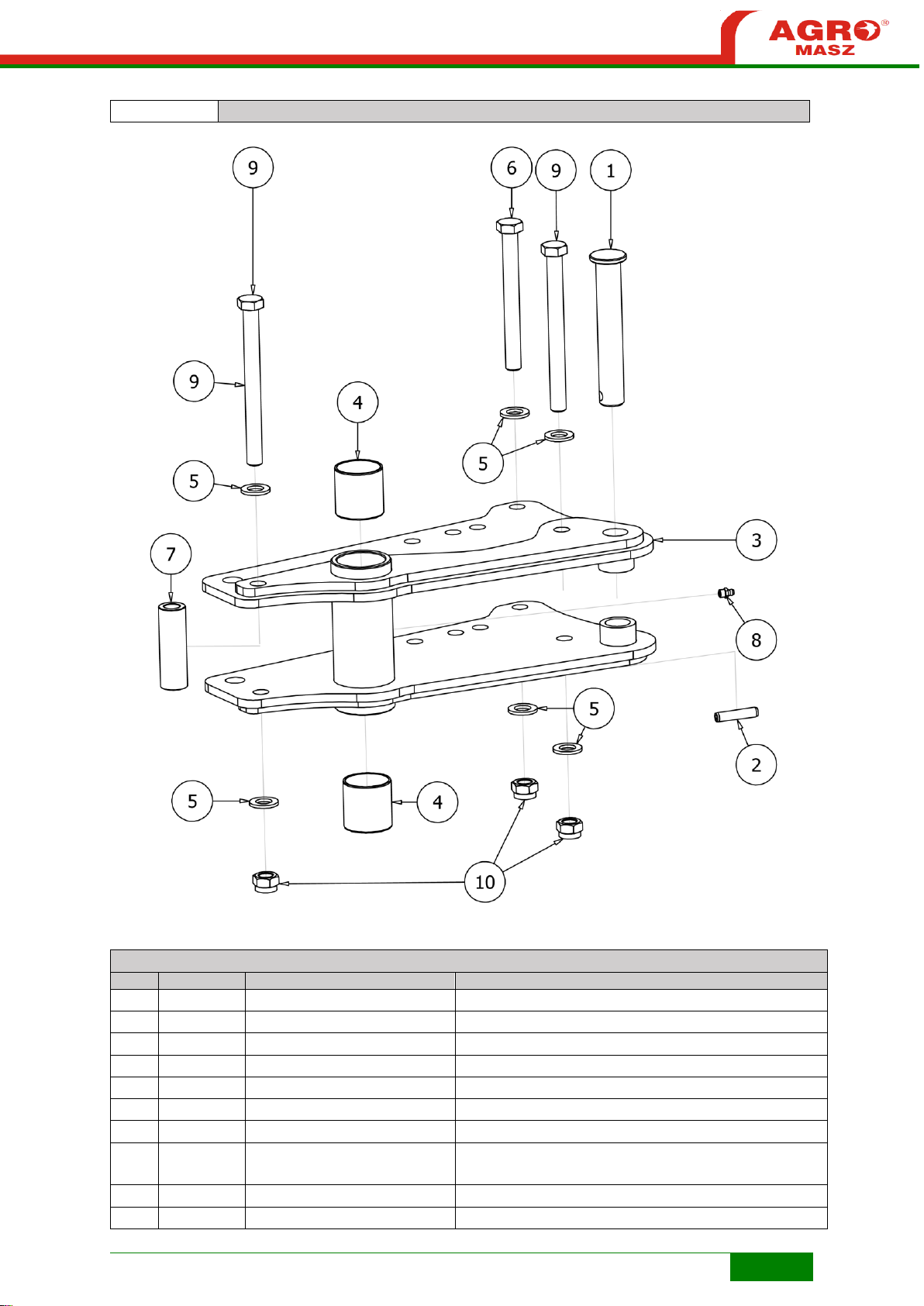
67
Fig. R5
PL01485 Coupling
LIST OF PARTS
NO.
QUANTITY
REFERENCE NUMBER
DESCRIPTION
1 1 PL01483
Pin dia25xL157
2 1 EL00044
Spring peg dia10xL45
3 1 PL01486
Connector
4 2 PL01351
Sliding sleeve 45x50
5 6 P16/O
Flat washer M16 zinc plated
6 1 S16x150/8.8/O
Bolt M16x150 8.8 zinc-plated
7 1 PL01495
Sleeve 16x28x89
8 1 EL00020
Grease nipple Type A DIN 71412 - AM8 x 1 conical
short
9 2 S16x170/8.8/O
Bolt M16x170 8.8 zinc-plated
10 3 NS16/O
Locknut M16 8 zinc plated
Page 68

68
Fig. R6
PL01487 Rotary plough POM body with mounting
LIST OF PARTS
NO.
QUANTITY
REFERENCE NUMBER
DESCRIPTION
1 1 PL01476
Second pair of bodies
2 1 PL01477
Pocket holder lower
3 1 PL01478
Pocket holder upper
4 2 P20/O
Flat washer M20 zinc plated
5 1 S20x150/8.8/O
Bolt M20x150 8.8 zinc-plated
6 1 NS20/O
Locknut M20 zinc plated
7
22
P16/O
Flat washer M16 zinc plated
8 4 S16x40/8.8/O
Bolt M16x40 8.8 zinc-plated
9
10
NS16/O
Locknut M16 8 zinc plated
10 1 N16/10/0
Flat washer M16 10 zinc plated
11 1 PL01518
Spacer dia20xL31.5
12 2 S16x140/8.8/O
Bolt M16x140 8.8 zinc plated
13 4 S16x75/8.8/O
Bolt M16x75 8.8 zinc-plated
14 1 PL01558-01
Reinforcement
Page 69
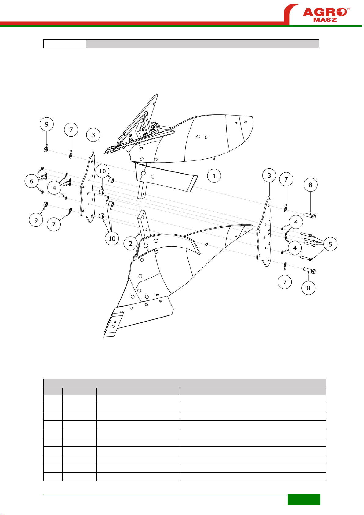
69
Fig. R7
PL01476 Rotary plough POM body
LIST OF PARTS
NO.
QUANTITY
REFERENCE NUMBER
DESCRIPTION
1 1 PL01443
Right frog complete POM
2 1 PL01449
Left frog complete POM
3 2 PL01457
Pocket vertical plate
4 8 P12/O
Flat washer M12 zinc plated
5 4 S12x70/8.8/O
Bolt M12x70 8.8 zinc-plated
6 4 N12/5.8/O
Flat washer M12 5.8 zinc plated
7 4 P20/O
Flat washer M20 zinc plated
8 2 S20x70/8.8/O
Bolt M20x70 8.8 zinc-plated
9 2 NS20/O
Locknut M20 zinc plated
10 5 PL01472
Spacer
Page 70
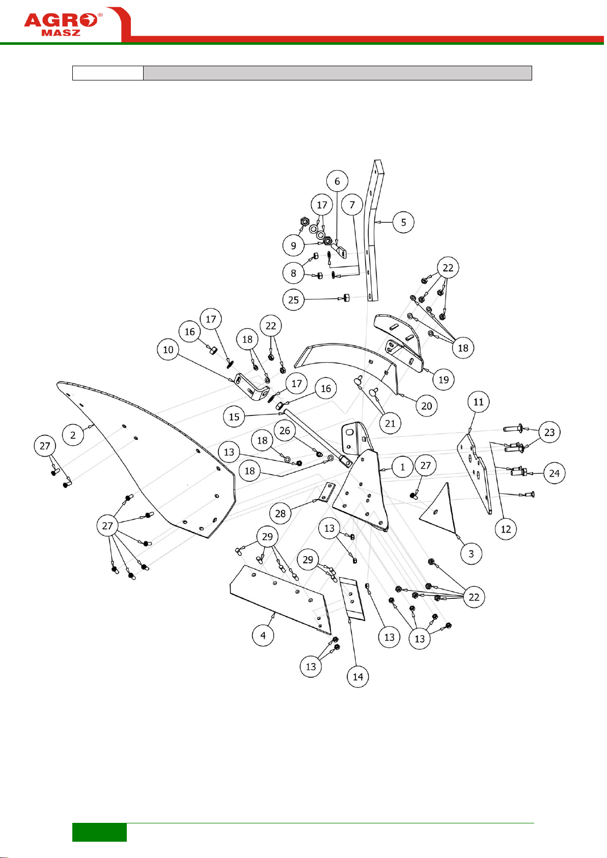
70
Fig. R8
PL01443 Right frog complete POM
Page 71
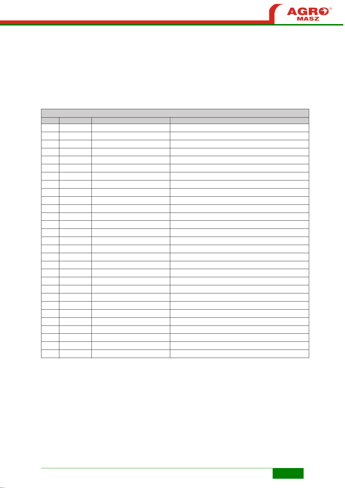
71
LIST OF PARTS
NO.
QUANTITY
REFERENCE NUMBER
DESCRIPTION
1 1 PL01436
Frog right PJL
2 1 PL01391
Mouldboard right 14"
3 1 PL01431
Breast right 14"
4 1 PL01429
Ploughshare right 14''
5 1 PL01444
Plough beam POM
6 1 PO.ET.00021
Angle adjustment screw
7 2 P16/O
Flat washer M16 zinc plated
8 2 N16/10/0
Flat washer M16 10 zinc plated
9 2 N20/8.0/C
Flat washer M20 8.0 black
10 1 PO.WG.00029
Support mounting
11 1 PL00871
Landside POL 2015
12 3 SP12x35/8.8/O
Plough bolt M12x35 8.8 zinc plated
13
10
N12/5.8/O
Flat washer M12 5.8 zinc plated
14 1 PL00342
Chisel right
15 1 PO.WG.00030
Board support
16 2 NS20/O
Locknut M20 zinc plated
17 4 P20/O
Flat washer M20 zinc plated
18 8 P12/O
Flat washer M12 zinc plated
19 1 PL01563
Trash board holder POM
20 1 PL01223
Trash board right 2016
21 2 SZ12x35/8.8/O
Coach bolt M12x35 8.8 zinc plated
22
11
N12/8.8/C
Flat washer M12 8,8 black
23 2 SZ16x70/8.8/O
Coach bolt M16x70 8.8 zinc plated
24 1 S20x50/8.8/O
Bolt M20x50 8.8 zinc-plated
25 1 N20/8.8/O
Nut M20 8.8 zinc plated
26 1 S12x35/8.8/O
Bolt M12x35 8.8 zinc-plated
27 9 PL02848
Plough bolt M12x35 12.9
28 1 PL00728
Ploughshare coupling with mouldboard
29 6 PL00785
Chisel bolt M12x40
Page 72
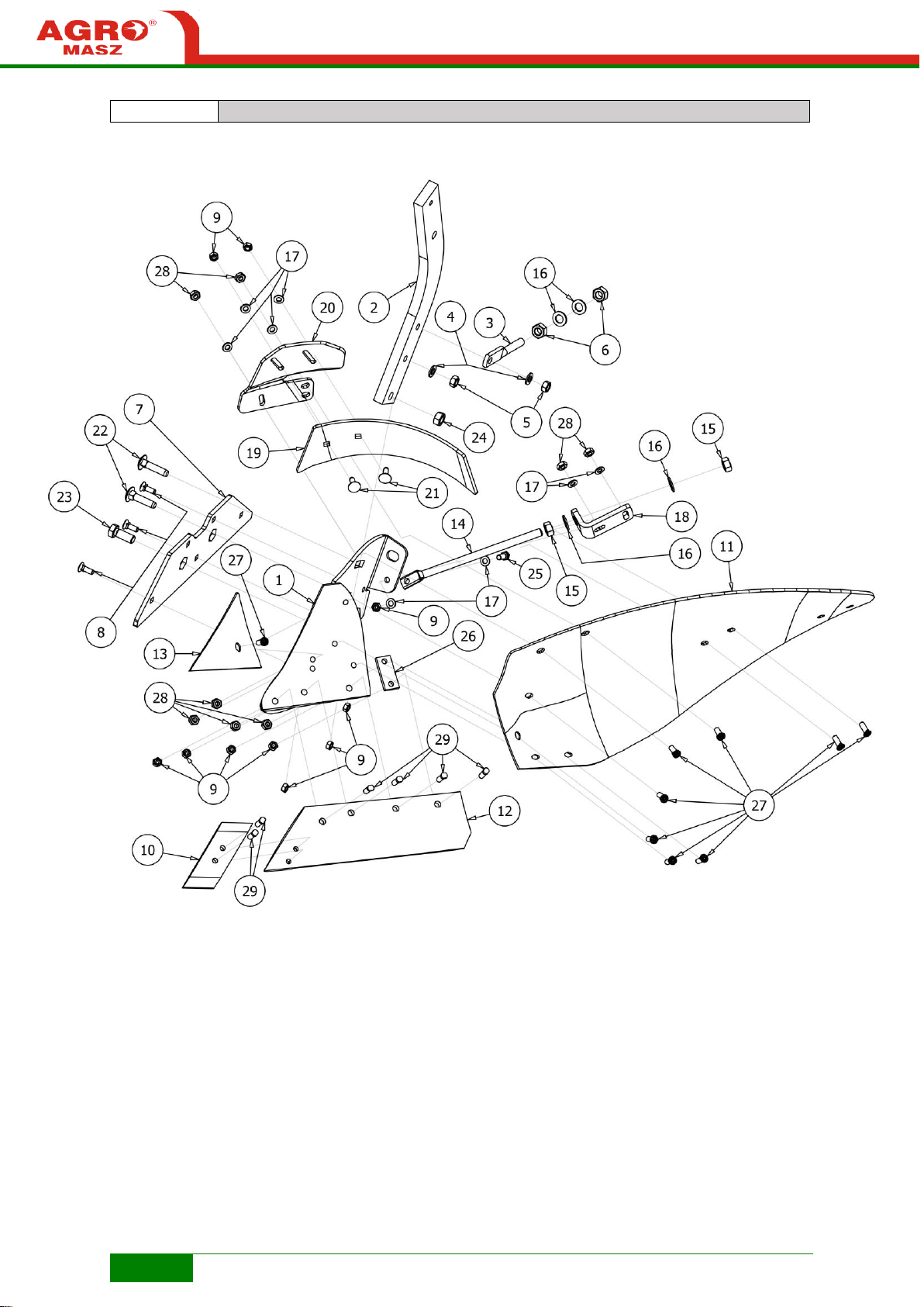
72
Fig. R9
PL01449 Left frog complete POM
Page 73
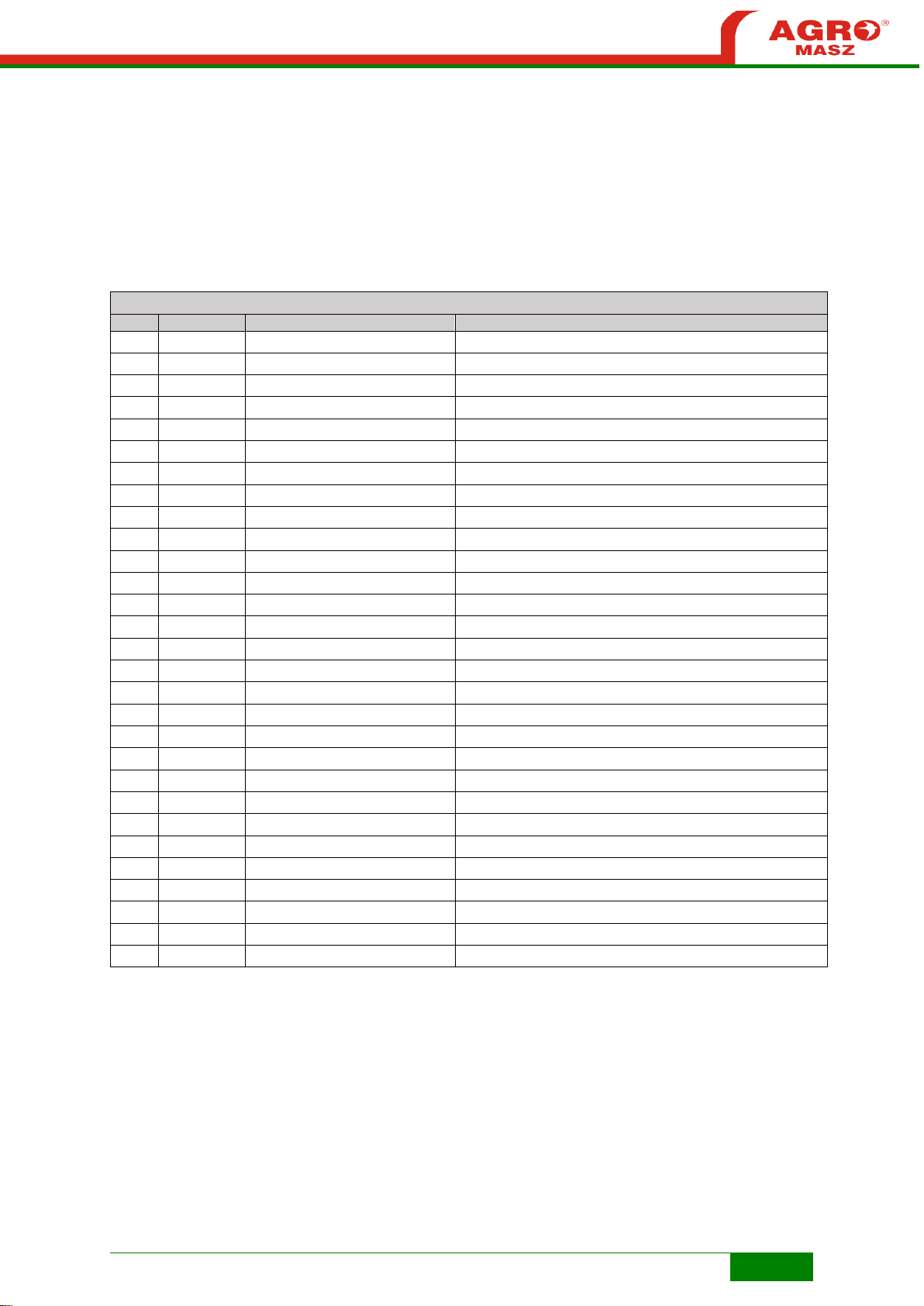
73
LIST OF PARTS
NO.
QUANTITY
REFERENCE NUMBER
DESCRIPTION
1 1 PL01448
Left frog
2 1 PL01444
Plough beam POM
3 1 PO.ET.00021
Angle adjustment screw
4 2 P16/O
Flat washer M16 zinc plated
5 2 N16/10/0
Flat washer M16 10 zinc plated
6 2 N20/8.0/C
Flat washer M20 8.0 black
7 1 PL00871
Landslide POL 2015
8 3 SP12x35/8.8/O
Plough bolt M12x35 8.8 zinc plated
9
12
N12/5.8/O
Flat washer M12 5.8 zinc plated
10 1 PL00343
Chisel left
11 1 PL01404
Mouldboard left 14''
12 1 PL01430
Ploughshare left 14''
13 1 PL01433
Breast left 14''
14 1 PO.WG.00030
Board support
15 2 NS20/O
Locknut M20 zinc plated
16 4 P20/O
Flat washer M20 zinc plated
17 8 P12/O
Flat washer M12 zinc plated
18 1 PO.WG.00029
Support mounting
19 1 PL01579
Trash board left 2016
20 1 PL01578
Trash board holder POM
21 2 SZ12x35/8.8/O
Coach bolt M12x35 8.8 zinc plated
22 2 SZ16x70/8.8/O
Coach bolt M16x70 8.8 zinc plated
23 1 S20x50/8.8/O
Bolt M20x50 8.8 zinc-plated
24 1 N20/8.8/O
Nut M20 8.8 zinc plated
25 1 S12x35/8.8/O
Bolt M12x35 8.8 zinc-plated
26 1 PL00728
Ploughshare coupling with mouldboard
27 9 PL02848
Plough bolt M12x35 12.9
28 9 N12/8.8/C
Flat washer M12 8.8 black
29 6 PL00785
Chisel bolt M12x40
Page 74

74
Fig. R13
PL01525 Ground-following wheel mechanism side frame 100x100
Page 75
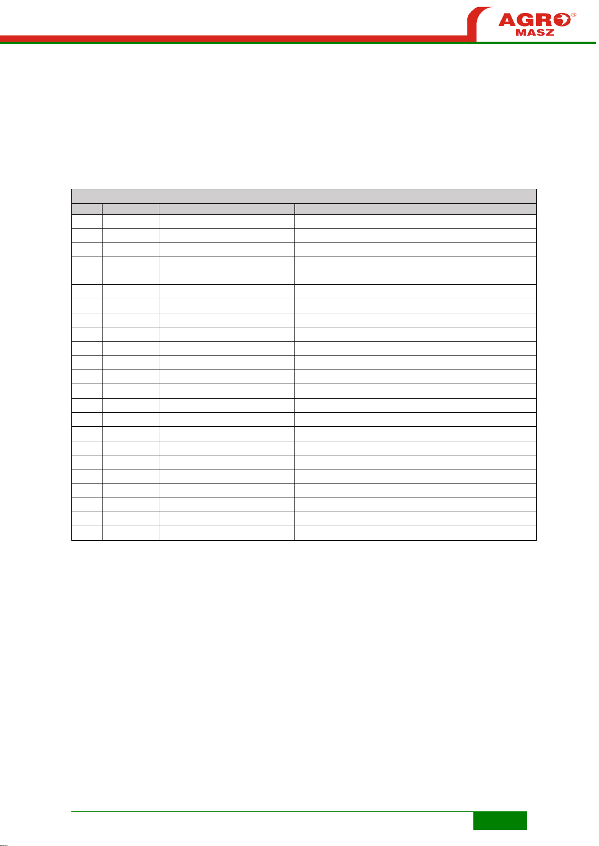
75
LIST OF PARTS
NO.
QUANTITY
REFERENCE NUMBER
DESCRIPTION
1 1 PL01523
Wheel mounting
2 1 PL01297
Mechanism for flat
3 2 S20x60/8.8/O
Bolt M20x60 8.8 zinc-plated
4 1 EL00020
Grease nipple Type A DIN 71412 - AM8 x 1 conical
short
5 1 PZ.EM.00003
Rim with tyre PZ40 PJ
6 1 PL01528
Wheel hub POM complete
7
16
P16/O
Flat washer M16 zinc plated
8 6 S16x45/8.8/O
Bolt zinc plated M16x45 grade 8.8
9 7 NS16/O
Locknut M16 8 zinc plated
10 2 NS20/O
Locknut M20 zinc plated
11 2 PL01243
Bearing washer MB09
12 2 EL00043
Bearing nut KM09
13 1 S16x110/8.8/O
Bolt M16x110 8.8 zinc plated
14 1 PL01298
Wheel arm
15 1 PL01301
Threaded rod mounting
16 1 PL01304
Threaded rod Tr 20x4
17 2 S16x40/8.8/O
Bolt M16x40 8.8 zinc-plated
18 1 PL01310
Washer 16x32.2x6
19 1 PL01311
Thread head
20 1 PL01312
Rotation lock
21 1 PL01267
Spring lock
22 1 EL00070
Dowel pin d6xL32
Page 76
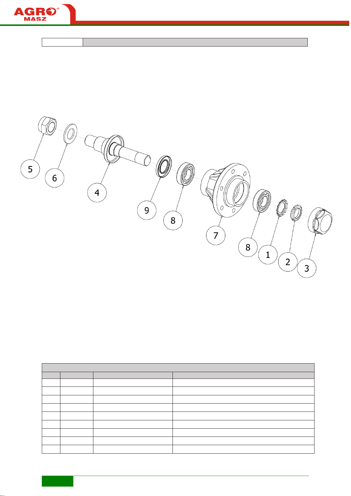
76
Fig. R14
PL01528 Wheel hub POM
LIST OF PARTS
NO.
QUANTITY
REFERENCE NUMBER
DESCRIPTION
1 1 EL00018
Bearing washer MB6
2 1 EL00019
Bearing nut KM6
3 1 PL00454
Hub dust nut
4 1 PL01527
Wheel axle POM
5 1 NS30/O
Locknut M30 zinc plated
6 1 P30/O
Flat washer M30 zinc plated
7 1 SI00916
Housing of maintenance-free hub (SR, PJ, PZ, POM)
8 2 EL00016
Tapered roller bearing 30206
9 1 EL00017
O-ring DIN 3760 - A - 35 x 62 x 7 - NBR
 Loading...