

Page 1
Threat Analysis Reporter
®
QUICK START
GUIDE
Model: TAR
MSA-004-004
Release: 1.1.15 / Updated: 02.29.08
Page 2

8e6 enterprise Filter Quick start Guide
© 2008 8e6 Technologies. All rights reserved.
This document may not, in whole or in part, be copied, photocopied, reproduced, translated, or reduced to any electronic medium or machine readable form without prior written consent from 8e6 Technologies.
Every effort has been made to ensure the accuracy of this document. However, 8e6 Technologies makes no war-
ranties with respect to this documentation and disclaims any implied warranties of merchantability and tness for a
particular purpose. 8e6 Technologies shall not be liable for any error or for incidental or consequential damages in
connection with the furnishing, performance, or use of this manual or the examples herein. The information in this
documentation is subject to change without notice.
The R3000 products have been tested and found to comply with the limits for a Class A digital device, pursuant to
part 15 of the FCC Rules. These limits are designed to provide reasonable protection against harmful interference
when the equipment is operated in a commercial environment. This equipment generates, uses, and can radiate radio
frequency energy and, if not installed and used in accordance with the instruction manual, may cause harmful interference to radio communications. Operation of this equipment in a residential area is likely to cause harmful interference in which case the user will be required to correct the interference at his own expense.
Trademarks
Other product names mentioned in this manual may be trademarks or registered trademarks of their respective companies and are the sole property of their respective manufacturers.
Part# TAR-MSAul-QSG-080229
ii 8e6 ThreaT analysis reporTer Quick sTarT Guide
Page 3

Contents
threat analysis reporter introduCtion ....................................................1
About this Document ....................................................................................................................2
Conventions Used in this Document ........................................................................................... 2
serviCe information .................................................................................. 3
preliminary setup proCedures ................................................................. 4
Unpack the Unit from the Carton .................................................................................................4
Select a Site for the Server ...........................................................................................................5
Rack Mount the Server ..................................................................................................................6
Check the Power Supply .............................................................................................................15
General Safety Information .........................................................................................................16
install the server ..................................................................................19
Step 1: Initial Setup Procedures ................................................................................................19
Step 1A: Step-by-Step Setup Procedures .................................................................................19
Step 2: Wizard Setup Procedures ..............................................................................................35
ConClusion ............................................................................................. 47
led indiCators and Buttons ...................................................................48
MSA Units .....................................................................................................................................48
regulatory speCifiCations and disClaimers .............................................49
Declaration of the Manufacturer or Importer ............................................................................49
appendix: optional ethernet tap installation ........................................ 51
Preliminary Setup Procedures ...................................................................................................51
Install the Ethernet Tap Unit .......................................................................................................52
index .......................................................................................................54
8e6 ThreaT analysis reporTer Quick sTarT Guide iii
Page 4

iv 8e6 ThreaT analysis reporTer Quick sTarT Guide
Page 5

threat analysis reporter introduCtion
Thank you for choosing to evaluate the 8e6 Technologies Threat Analysis Reporter. This
product addresses user-generated Web threats such as excessive use of bandwidth
and inappropriate Internet usage, and provides network administrators tools to monitor
such threats so management can enforce corporate Internet usage policies.
Working in conjunction with 8e6’s R3000 Enterprise Filter, the Threat Analysis Reporter
translates end user Internet activity from the R3000’s logs into dynamic graphical snap-
shots of network Internet trafc. Using remediation tools in the console, administrators
and management can then manage and control user-generated Web threats in real
time.
8e6 ThreaT analysis reporTer Quick sTarT Guide 1
Page 6
About this Document
This document is divided into the following sections:
Introduction - This section is comprised of an overview of the Threat Analysis Re-
•
porter product and how to use this document
Service Information - This section provides 8e6 Technologies contact information
•
Preliminary Setup Procedures - This section includes instructions on how to physi-
•
cally set up the Threat Analysis Reporter unit in your network environment
Install the Server - This section explains how to congure the Threat Analysis Re-
•
porter
Conclusion - This section indicates that the quick start steps have been completed
•
LED Indicators and Buttons - This section explains how to read LED indicators
•
and use LED buttons for troubleshooting the unit
Regulatory Specications and Disclaimers - This section cites safety and emis-
•
sions compliance information for the TAR model referenced in this document
Appendix: Optional Ethernet Tap Installation - This appendix explains how to
•
install the optional Ethernet Tap device on your network for bandwidth monitoring
Index - An alphabetized list of some topics included in this document
•
Conventions Used in this Document
The following icons are used throughout this document to call attention to important
information pertaining to handling, operation, and maintenance of the server; safety and
preservation of the equipment, and personal safety:
NOTE: The “note” icon is followed by additional information to be consid-
ered.
WARNING: The “warning” icon is followed by information alerting you to a
potential situation that may cause damage to property or equipment.
CAUTION: The “caution” icon is followed by information warning you that a
situation has the potential to cause bodily harm or death.
2 8e6 ThreaT analysis reporTer Quick sTarT Guide
Page 7

serviCe information
The user should not attempt any maintenance or service on the unit beyond the procedures outlined in this document.
Any initial hardware setup problem that cannot be resolved at your internal organization should be referred to an 8e6 Technologies solutions engineer or technical support
representative.
8e6 Corporate Headquarters (USA)
Local : 714.282.6111
Domestic US : 1.888.786.7999
International : +1.714.282.6111
8e6 Taiwan
Taipei Local : 2397-0300
Domestic Taiwan : 02-2397-0300
International : 886-2-2397-0300
Procedures
When calling 8e6 Technologies regarding a problem, please provide the representative
the following information:
Your contact information.
•
Serial number or original order number.
•
Description of the problem.
•
Network environment in which the unit is used.
•
State of the unit before the problem occurred.
•
Frequency and repeatability of the problem.
•
Can the product continue to operate with this problem?
•
Can you identify anything that may have caused the problem?
•
8e6 ThreaT analysis reporTer Quick sTarT Guide 3
Page 8
preliminary setup proCedures
Unpack the Unit from the Carton
Inspect the packaging container for evidence of mishandling during transit. If the packaging container is damaged, photograph it for reference.
Carefully unpack the unit from the carton and verify that all accessories are included.
Save all packing materials in the event that the unit needs to be returned to 8e6 Technologies.
The carton should contain the following items:
1 Threat Analysis Reporter unit
•
1 AC Power Cord
•
1 Serial Port Cable
•
1 CAT-5E Crossover Cable
•
Rack Mount Brackets (2)
•
1 End User License Agreement (EULA)
•
1 envelope containing a CD-ROM with a PDF of the Threat Analysis Reporter User
•
Guide. The latest version of the user guide can be obtained from our Web site at
http://www.8e6.com/docs/tar_ug.pdf.
NOTES: A coupler is included in the carton if a three-foot CAT-5E crossover
cable is packaged with your unit instead of a 14-foot CAT-5E crossover cable.
Inspect the server and accessories for damage. If the contents appear damaged, le a
damage claim with the carrier immediately.
WARNING: To avoid danger of suffocation, do not leave plastic bags used for
packaging the server or any of its components in places where children or infants
may play with them.
4 8e6 ThreaT analysis reporTer Quick sTarT Guide
Page 9

Select a Site for the Server
The server operates reliably within normal ofce environmental limits. Select a site that
meets the following criteria:
Clean and relatively free of excess dust.
•
Well-ventilated and away from sources of heat, with the ventilating openings on the
•
server kept free of obstructions.
Away from sources of vibration or physical shock.
•
Isolated from strong electromagnetic elds and noise caused by electrical devices
•
such as elevators, copy machines, air conditioners, large fans, large electric motors,
radio and TV transmitters, and high-frequency security devices.
Access space provided so the server power cord can be unplugged from the power
•
supply or the wall outlet—this is the only way to remove the AC power cord from the
server.
Clearance provided for cooling and airow: Approximately 30 inches (76.2 cm) in the
•
back and 25 inches (63.5 cm) in the front.
Located near a properly earthed, grounded, power outlet.
•
8e6 ThreaT analysis reporTer Quick sTarT Guide 5
Page 10
Rack Mount the Server
Rack Setup Precautions
Warning:
Before rack mounting the server, the physical environment should be set up to safely accommodate the server. Be sure that:
The weight of all units in the rack is evenly distributed. Mounting of the equipment in
•
the rack should be such that a hazardous condition is not achieved due to uneven
mechanical loading.
The rack will not tip over when the server is mounted, even when the unit is fully
•
extended from the rack.
For a single rack installation, stabilizers are attached to the rack.
•
For multiple rack installations, racks are coupled together.
•
Reliable earthing of rack-mounted equipment is maintained at all times. Particular
•
attention should be given to supply connections other than direct connections to the
branch circuit (e.g. use of power strips).
A power cord will be long enough to t into the server when properly mounted in the
•
rack and will be able to supply power to the unit.
The connection of the server to the power supply will not overload any circuits. Con-
•
sideration should be given to the connection of the equipment to the supply circuit
and the effect that overloading of the circuits might have on overcurrent protection
and supply wiring. Appropriate consideration of equipment nameplate ratings should
be used when addressing this concern.
The server is only connected to a properly rated supply circuit. Reliable earthing
•
(grounding) of rack-mounted equipment should be maintained.
The air ow through the server’s fan or vents is not restricted. Installation of the
•
equipment in a rack should be such that the amount of air ow required for safe operation of the equipment is not compromised.
The maximum operating ambient temperature does not exceed 104°F (40°C). If
•
installed in a closed or multi-unit rack assembly, the operating ambient temperature
of the rack environment may be greater than room ambient. Therefore, consideration
should be given to installing the equipment in an environment compatible with the
maximum ambient temperature (Tma) specied by the manufacturer.
WARNING: Extend only one component at a time. Extending two or more
components simultaneously may cause the rack to become unstable
6 8e6 ThreaT analysis reporTer Quick sTarT Guide
Page 11
Rack Mount Instructions
Optional: Install the Chassis Rails
NOTE: If your chassis does not come with chassis rails, please follow the
procedure listed on the last page of this sub-section to install the unit directly into
the rack.
CAUTION: Please make sure that the chassis covers and chassis rails are
installed on the chassis before you install the chassis into the rack. To avoid
personal injury and property damage, please carefully follow all the safety steps
listed below:
Before installing the chassis rails:
• Close the chassis using the chassis cover.
• Unplug the AC power cord(s).
• Remove all external devices and connectors.
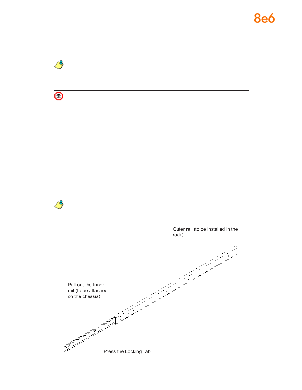
1. Included in the shipping package are a pair of rail assemblies. In each rail assembly,
locate the inner rail and the outer rail.
2. Press the locking tab to release the inner rail from its locking position and pull out
the inner rail from the rail assembly.
NOTE: The inner rails are to be attached to the chassis and the outer rails
are to be installed in the rack.
8e6 ThreaT analysis reporTer Quick sTarT Guide 7
Page 12
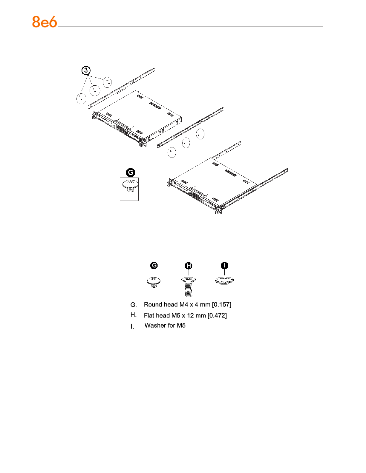
3. Locate the three holes on each side of the chassis and locate the three correspond-
ing holes on each of the inner rail.
4. Attach an inner rail to each side of the chassis and secure the inner rail to the chas-
sis by inserting three Type G screws through the holes on each side of the chassis
and the inner rail. (See the diagram below for a description of the Type G screw.)
5. Repeat the above steps to install the other rail on the chassis.
8 8e6 ThreaT analysis reporTer Quick sTarT Guide
Page 13
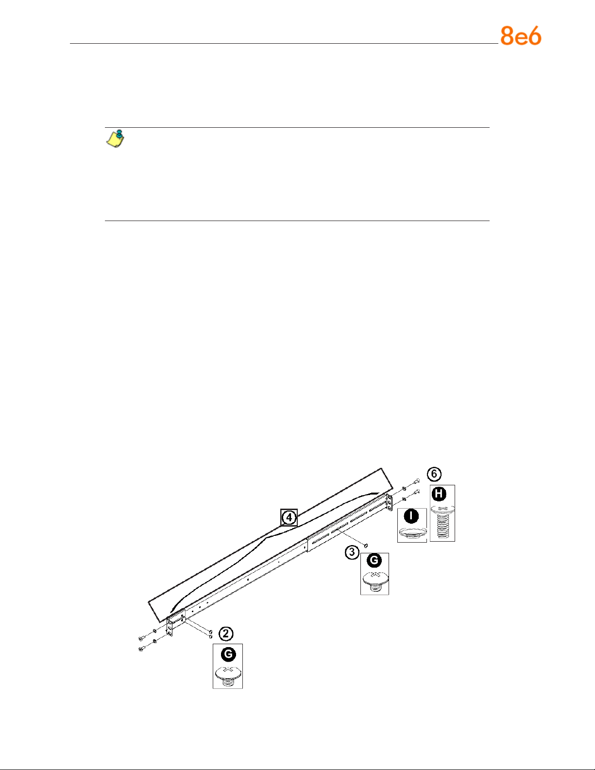
Optional: Install the Traditional UP Racks
After you have installed the inner rails on the chassis, you are ready to install the outer
rails of rail assemblies to the rack.
NOTE: The rails are designed to t in the racks with the depth of 28” to 33”.
• Determine the placement of each component in the rack before you install the
rails.
• Install the heaviest server components on the bottom of the rack rst, and
then work up.
1. In the package, locate a pair of front (short) and rear (long) brackets. Please note
that the brackets are marked with Up/Front Arrows (front) and Up/Rear arrows (rear).
2. Secure the front (short) bracket (marked with the Up/Front arrows) to the outer rail
with two Type G screws. (See the previous page for a description of the Type G
screw.)
3. Attach the rear (long) bracket to the other end of the outer rail and secure the rear
(long) bracket to the outer rail with a Type G screw as shown below.
4. Measure the depth of your rack and adjust the length of the rails accordingly.
5. Repeat the same steps to install the other outer rail on the chassis.
6. Secure both outer rail assemblies to the rack with Type H screws and Type I washers. (See the previous page for descriptions of Type H and Type I hardware components.)
8e6 ThreaT analysis reporTer Quick sTarT Guide 9
Page 14
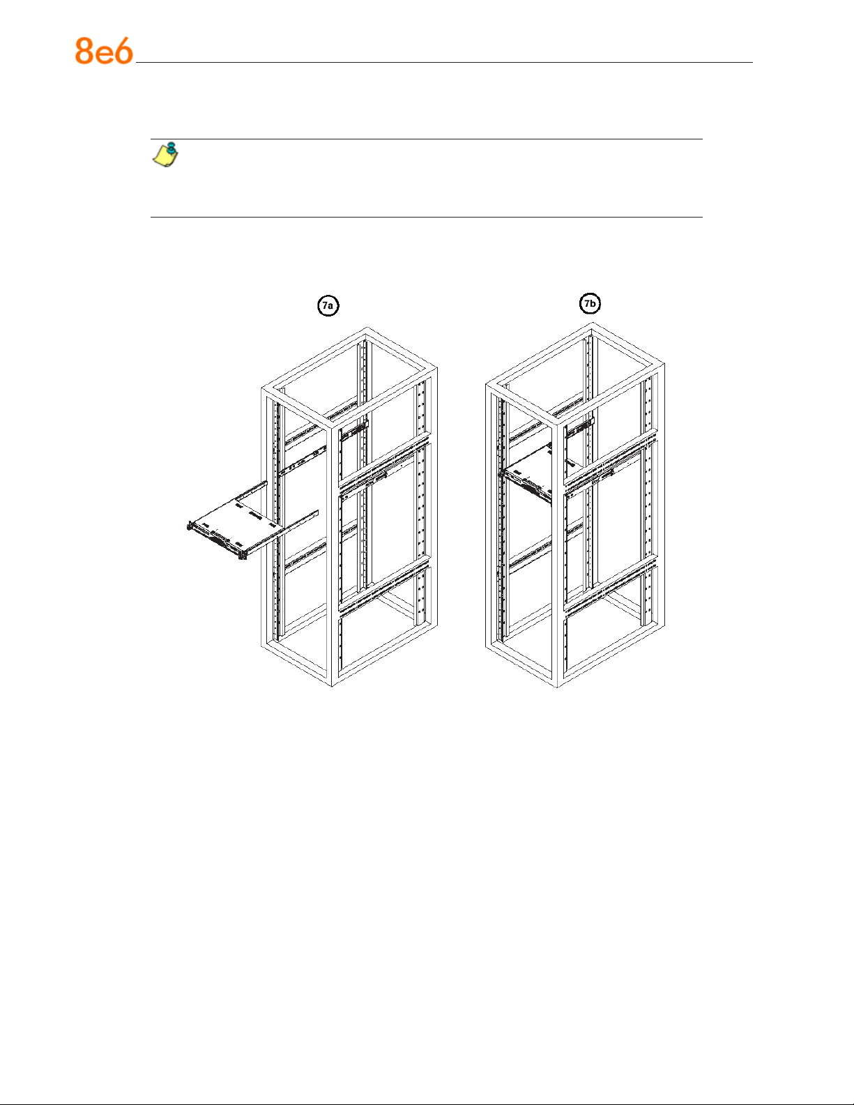
7. Slide the chassis into the rack as shown below.
NOTE: The chassis may not slide into the rack smoothly or easily when installed
the rst time. Some adjustment to the slide assemblies might be needed for easy
installation.
8. You will need to release the safety taps on both sides of the chassis in order to completely remove the chassis out of the rack.
10 8e6 ThreaT analysis reporTer Quick sTarT Guide
Page 15
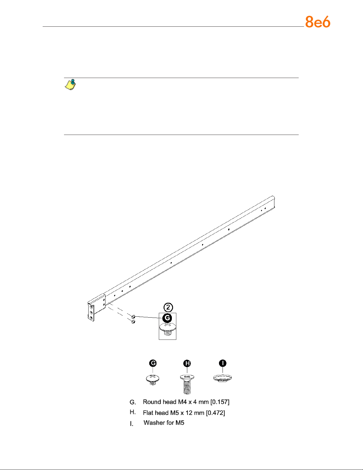
Optional: Install the Open Racks
After you have installed the inner rails on the chassis, you are ready to install the outer
rails of rail assemblies to the rack.
NOTE: The rails are designed to t in the racks with the depth of 28” to 33”.
• Determine the placement of each component in the rack before you install the
rails.
• Install the heaviest server components on the bottom of the rack rst, and
then work up.
1. In the package, locate a pair of front (short) and rear (long) brackets. Please note
that the brackets are marked with Up/Front Arrows (front) and Up/Rear arrows (rear).
2. Secure the front (short) bracket (marked with the Up/Front arrows) to the outer rail
with two Type G screws as shown below.
8e6 ThreaT analysis reporTer Quick sTarT Guide 11
Page 16
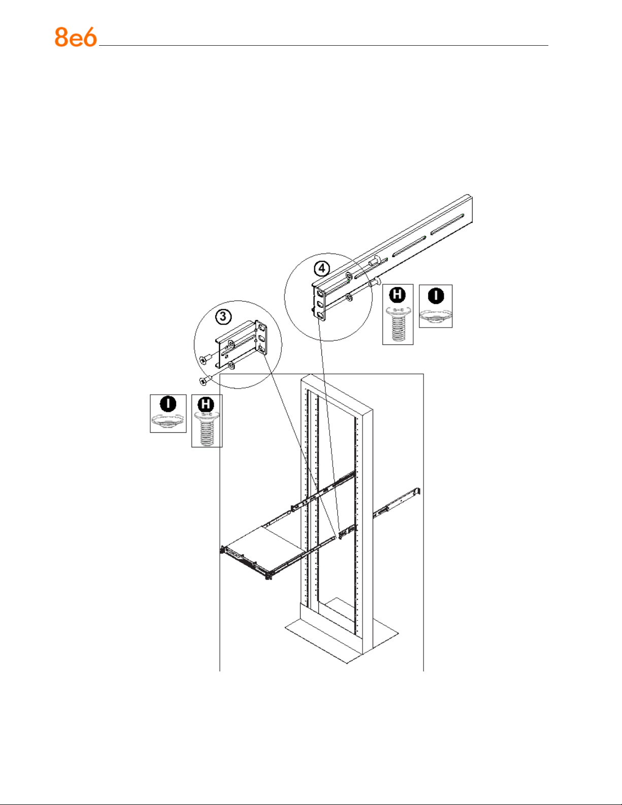
3. Attach the front (short) bracket to the front end of the rack, and secure it to the rack
with two Type H screws and Type I washers as shown below. (See the previous page
for descriptions of Type H and Type I hardware components.)
4. Attach the rear (long) bracket to the rear end of the rack, and secure it to the rack
with two Type H screws and Type I washers as shown below. Repeat the same steps
to install the other outer rail to the other side of rack.
5. Measure the depth of your rack and adjust the length of the rails accordingly. Then,
secure the rails to the chassis with Type G screws.
12 8e6 ThreaT analysis reporTer Quick sTarT Guide
Page 17
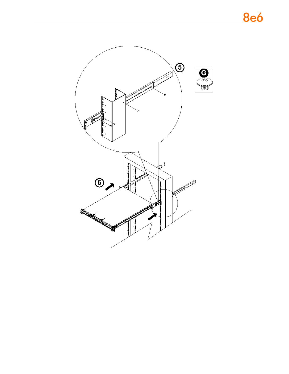
6. Slide the inner rails which are attached to the chassis into the outer rails on the rack.
8e6 ThreaT analysis reporTer Quick sTarT Guide 13
Page 18
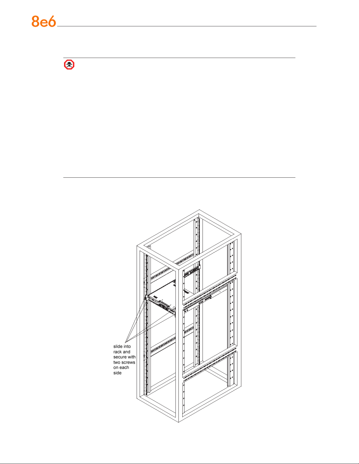
Install the Chassis into the Rack
CAUTION: Before installing the chassis into the rack:
• Make sure that the rack is securely anchored onto an unmovable surface or
structure before installing the chassis into the rack.
• Unplug power cord(s) of the rack before installing the chassis into the rack.
• Make sure that the system is adequately supported. Make sure that all the
components are securely fastened to the chassis to prevent components falling off from the chassis.
• The rack assembly should be properly grounded to avoid electric shock.
• The rack assembly must provide sufcient airow to the chassis for proper
cooling.
• Please make sure that all components and all chassis covers are properly installed in the chassis before you install the chassis into the racks; otherwise,
out-of-warranty damage may occur.
Slide the chassis into the rack and secure it with two screws on each side of the rack as
shown in the picture.
14 8e6 ThreaT analysis reporTer Quick sTarT Guide
Page 19
Check the Power Supply
This server is equipped with a universal power supply that handles 100-240 V, 50/60 Hz.
A standard power cord interface (IEC 950) facilitates power plugs that are suitable for
most European, North American, and Pacic Rim countries.
Power Supply Precautions
Warning:
Use a regulating uninterruptible power supply (UPS) to protect the server from power
•
surges, voltage spikes and to keep the server operating in case of a power failure.
In geographic regions that are susceptible to electrical storms, 8e6 highly recom-
•
mends plugging the AC power cord for the server into a surge suppressor.
Use appropriately rated extension cords or power strips only.
•
Allow power supply units to cool before touching them.
•
8e6 ThreaT analysis reporTer Quick sTarT Guide 15
Page 20
General Safety Information
Server Operation and Maintenance Precautions
Warning:
Observe the following safety precautions during server operation and maintenance:
WARNING: If the server is used in a manner not specied by the manufacturer,
the protection provided by the server may be impaired.
WARNING: 8e6 Technologies is not responsible for regulatory compliance
of any server that has been modied. Altering the server’s enclosure in any way
other than the installation operations specied in this document may invalidate the
server’s safety certications.
CAUTION: Never pile books, papers, or other objects on the chassis, drop it,
or subject it to pressure in any other way. The internal circuits can be damaged,
and the battery may be crushed or punctured. Besides irreparable damage to the
unit, the result could be dangerous heat and even re.
CAUTION: There are no user-serviceable components inside the chassis.
The chassis should only be opened by qualied service personnel. Never disassemble, tamper with, or attempt to repair the server. Doing so may cause smoke,
re, electrical shock, serious physical injury, or death.
Do not insert objects through openings in the chassis. Doing so could result in a
•
short circuit that might cause a re or an electrical shock.
Do not operate the server in an explosive atmosphere, in the presence of ammable
•
gases.
To ensure proper cooling, always operate the server with its covers in place. Do not
•
block any openings on the chassis. Do not place the server near a heater.
Always exit the software application properly before turning off the server to ensure
•
data integrity.
Do not expose the server to rain or use near water. If liquids of any kind should leak
•
into the chassis, power down the server, unplug it, and contact 8e6 Technologies
technical support.
Disconnect power from the server before cleaning the unit. Do not use liquid or aero-
•
sol cleaners.
16 8e6 ThreaT analysis reporTer Quick sTarT Guide
Page 21
AC Power Cord and Cable Precautions
Warning:
The AC power cord for the server must be plugged into a grounded, power outlet.
•
Do not modify or use a supplied AC power cord if it is not the exact type required in
•
the region where the server will be installed and used. Replace the cord with the correct type.
Route the AC power cord and cables away from moving parts and foot trafc.
•
Do not allow anything to rest on the AC power cord and cables.
•
Never use the server if the AC power cord has been damaged.
•
Always unplug the AC power cord before removing the unit for servicing.
•
Electrical Safety Precautions
Warning:
Heed the following safety precautions to protect yourself from harm and the server from
damage:
CAUTION: Dangerous voltages associated with the 100-240 V AC power supply
are present inside the unit. To avoid injury or electrical shock, do not touch exposed
connections or components while the power is on.
To prevent damage to the server, read the information in this document for selection
•
of the proper input voltage.
Do not wear rings or wristwatches when troubleshooting electrical circuits.
•
To avoid re hazard, use only the specied fuse(s) with the correct type number, volt-
•
age, and current ratings. Only qualied service personnel should replace fuses.
Qualied service personnel should be properly grounded when servicing the unit.
•
Qualied service personnel should perform a safety check after any service is per-
•
formed.
8e6 ThreaT analysis reporTer Quick sTarT Guide 17
Page 22
Motherboard Battery Precautions
Caution:
The battery on the motherboard should not be replaced without following instructions
provided by the manufacturer. Only qualied service personnel should replace batteries.
The battery contains energy and, as with all batteries, a malfunction can cause heat,
smoke, or re, release toxic materials, or cause burns. Do not disassemble, puncture,
drop, crush, bend, deform, submerge or modify the battery. Do not incinerate or expose
to heat above 140°F (60°C).
There is a danger of explosion if the battery on the motherboard is installed upside
down, which will reverse its polarities.
CAUTION: DANGER OF EXPLOSION IF BATTERY IS INCORRECTLY REPLACED.
REPLACE ONLY WITH THE SAME OR EQUIVALENT TYPE RECOMMENDED BY
THE MANUFACTURER. DISPOSE OF THE USED BATTERIES ACCORDING TO THE
MANUFACTURER’S INSTRUCTIONS.
ATTENTION: IL Y A DANGER D’EXPLOSION S’IL Y A REPLACEMENT INCORRECT
DE LA BATTERIE, REMPLACER UNIQUEMENT AVEC UNE BATTERIE DU MÊME
TYPE OU D’UN TYPE ÉQUIVALENT RECOMMANDÉ PAR LE CONSTRUCTEUR.
METTRE AU REBUT LES BATTERIES USAGÉES CONFORMÊMENT AUX INSTRUCTIONS DU FABRICANT.
18 8e6 ThreaT analysis reporTer Quick sTarT Guide
Page 23
install the server
Step 1: Initial Setup Procedures
This step requires you to link the workstation to the Threat Analysis Reporter. You have
the option of using the text-based step-by-step setup procedures described in Step 1A.
Step-by-Step Setup Requirements
Threat Analysis Reporter unit with AC power cord
•
either one of two options:
•
PC monitor with AC power cord and keyboard, or
•
PC laptop computer with HyperTerminal and serial port cable (and USB DB9 se-
•
rial adapter, if there is no serial port on your laptop)
NOTE: Before installing the Threat Analysis Reporter server, the R3000 server
to be used with this server must already be installed and running software version
2.0.10 or higher.
Go to Step 1A to execute Step-by-Step Setup Procedures.
Step 1A: Step-by-Step Setup Procedures
Link the Workstation to the Threat Analysis Reporter
Monitor and Keyboard Setup
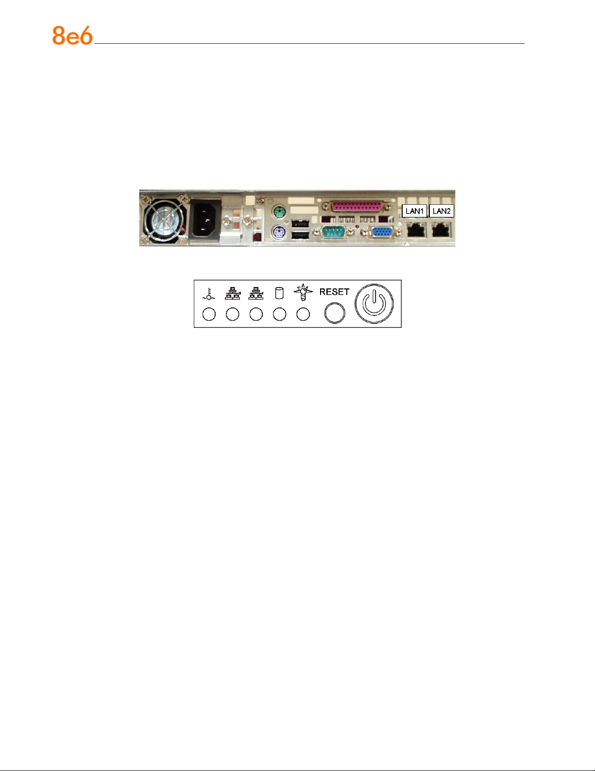
A. Connect the PC monitor and keyboard cables to the rear of the chassis (see Fig. 1).
B. Turn on the PC monitor.
C. Power on the Threat Analysis Reporter by dropping down the face plate and pressing
the large button at the right of the front panel (see Fig. 2).
Once the Threat Analysis Reporter is powered up, proceed to the Step-by-Step Initial
Setup Procedures instructions.
8e6 ThreaT analysis reporTer Quick sTarT Guide 19
Page 24
Serial Console Setup
A. Using the serial port cable (and USB DB9 serial adapter, if necessary), connect the
laptop to the rear of the chassis (see Fig. 1).
B. Power on the laptop.
C. Power on the Threat Analysis Reporter by pressing the large button on the front
panel (see Fig. 2).
Fig. 1 - Portion of chassis rear
Fig. 2 - Diagram of chassis front panel, power button at far right
Once the Threat Analysis Reporter is powered up, proceed to the instructions for HyperTerminal Setup Procedures.
20 8e6 ThreaT analysis reporTer Quick sTarT Guide
Page 25
HyperTerminal Setup Procedures
If using a serial console, follow these procedures to create a HyperTerminal session on
the serial console.
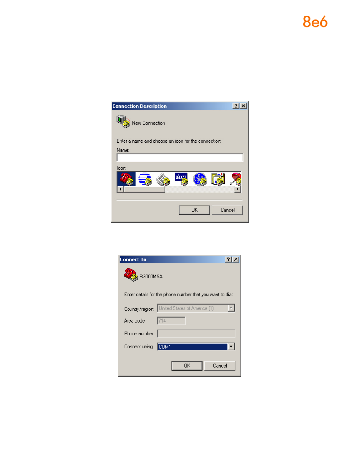
A. Launch HyperTerminal by going to Start > Programs > Accessories > Communica-
tions > HyperTerminal:
B. In the Connection Description dialog box, enter any session Name, and then click
OK to open the Connect To dialog box:
8e6 ThreaT analysis reporTer Quick sTarT Guide 21
Page 26
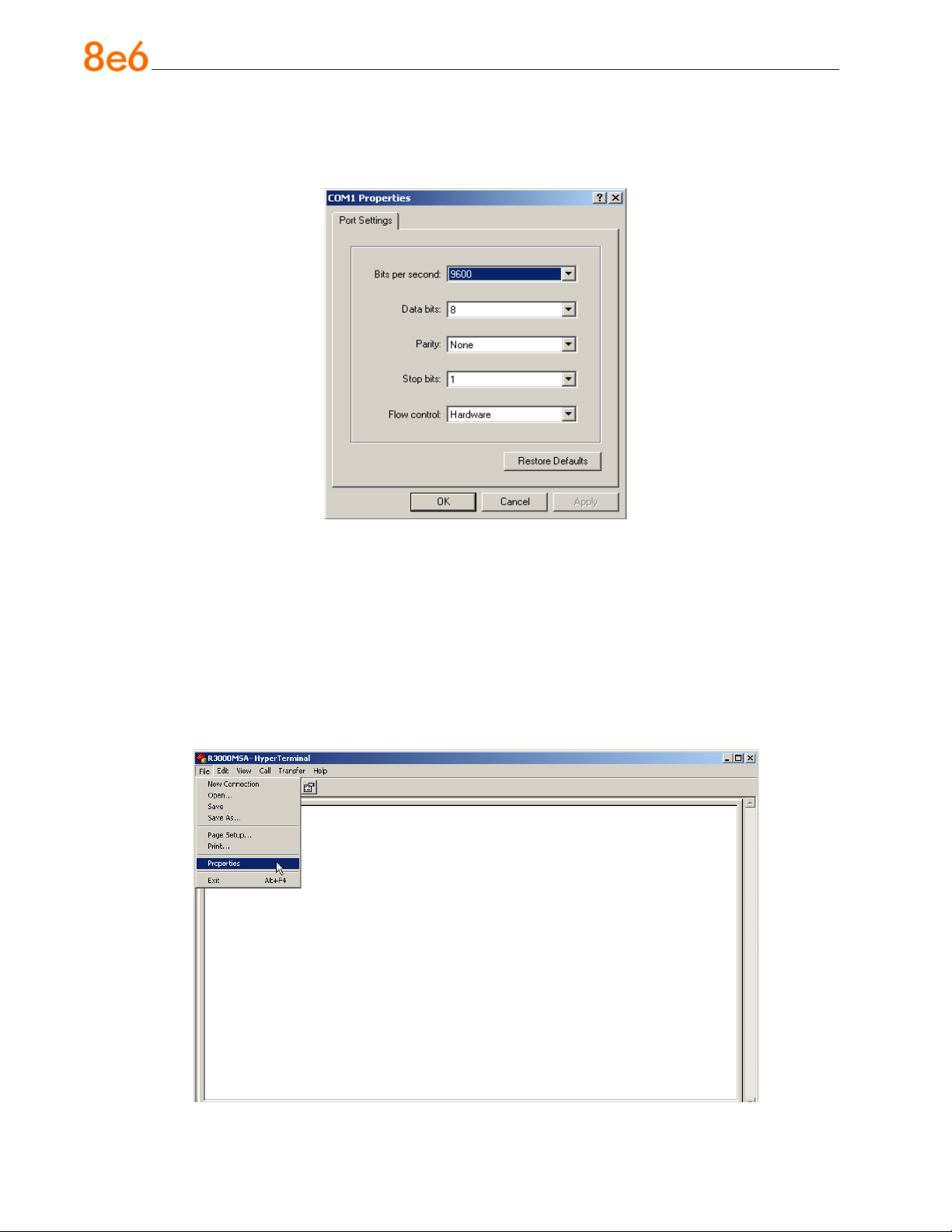
C. At the Connect using eld, select the COM port assigned to the serial port on the
laptop (probably “COM1”), and then click OK to open the Properties dialog box, displaying the Port Settings tab:
D. Specify the following session settings:
Bits per second: 9600
•
Data bits: 8
•
Parity: None
•
Stop bits: 1
•
Flow control: Hardware
•
E. Click OK to connect to the HyperTerminal session:
22 8e6 ThreaT analysis reporTer Quick sTarT Guide
Page 27
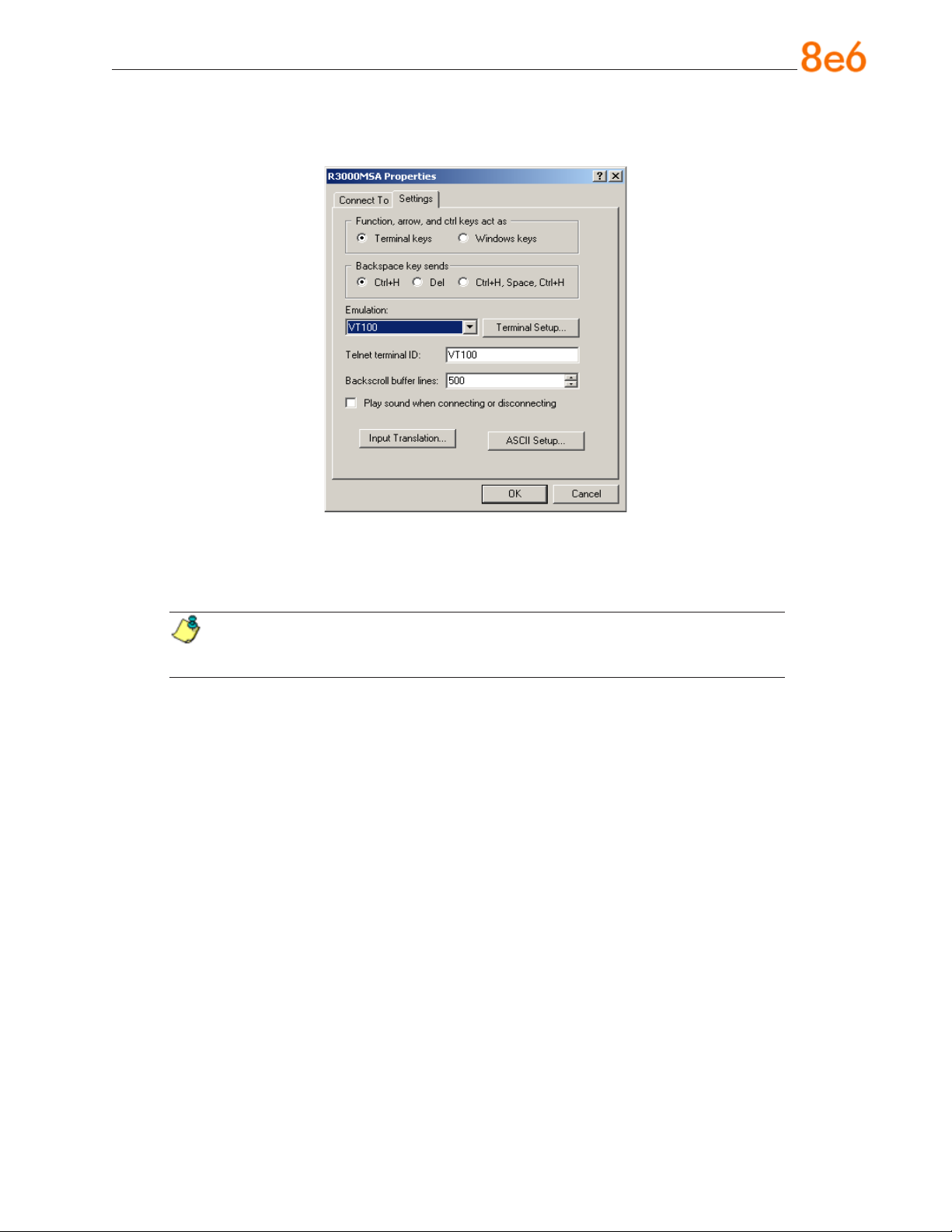
F. In the HyperTerminal session window, go to File > Properties to open the Properties
dialog box, displaying the Connect To and Settings tabs:
G. Click the Settings tab, and at the Emulation menu select “VT100”.
H. Click OK to close the dialog box, and to go to the login screen.
NOTE: If using a HyperTerminal session, the login screen will display with
black text on a white background.
8e6 ThreaT analysis reporTer Quick sTarT Guide 23
Page 28
Step-by-Step Initial Setup Procedures
For these step-by-step setup procedures, you will need your network administrator to
provide you the LAN 1 and LAN 2 IP address and subnet mask, gateway IP address,
DNS server IP address(es), host name of the server, and IP address for the Web interface (if using a NAT device).
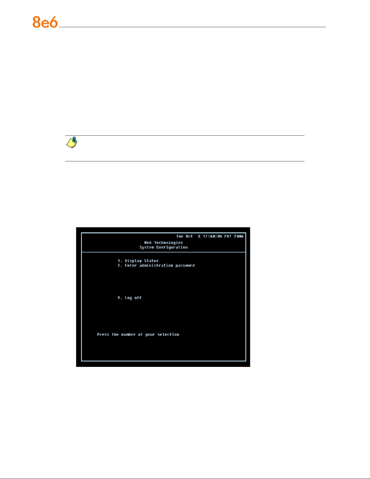
Login screen, password prompts
The login screen displays after powering on the Threat Analysis Reporter unit using a
monitor and keyboard, or after creating a HyperTerminal session.
NOTE: If the screensaver currently displays on your screen, press the Enter
key to display the login screen.
A. At the login prompt, type in menu.
B. Press the Enter key to display the Password prompt.
C. At the Password prompt, type in the following: #s3tup#r3k
D. Press Enter to display the System Conguration screen:
24 8e6 ThreaT analysis reporTer Quick sTarT Guide
Page 29
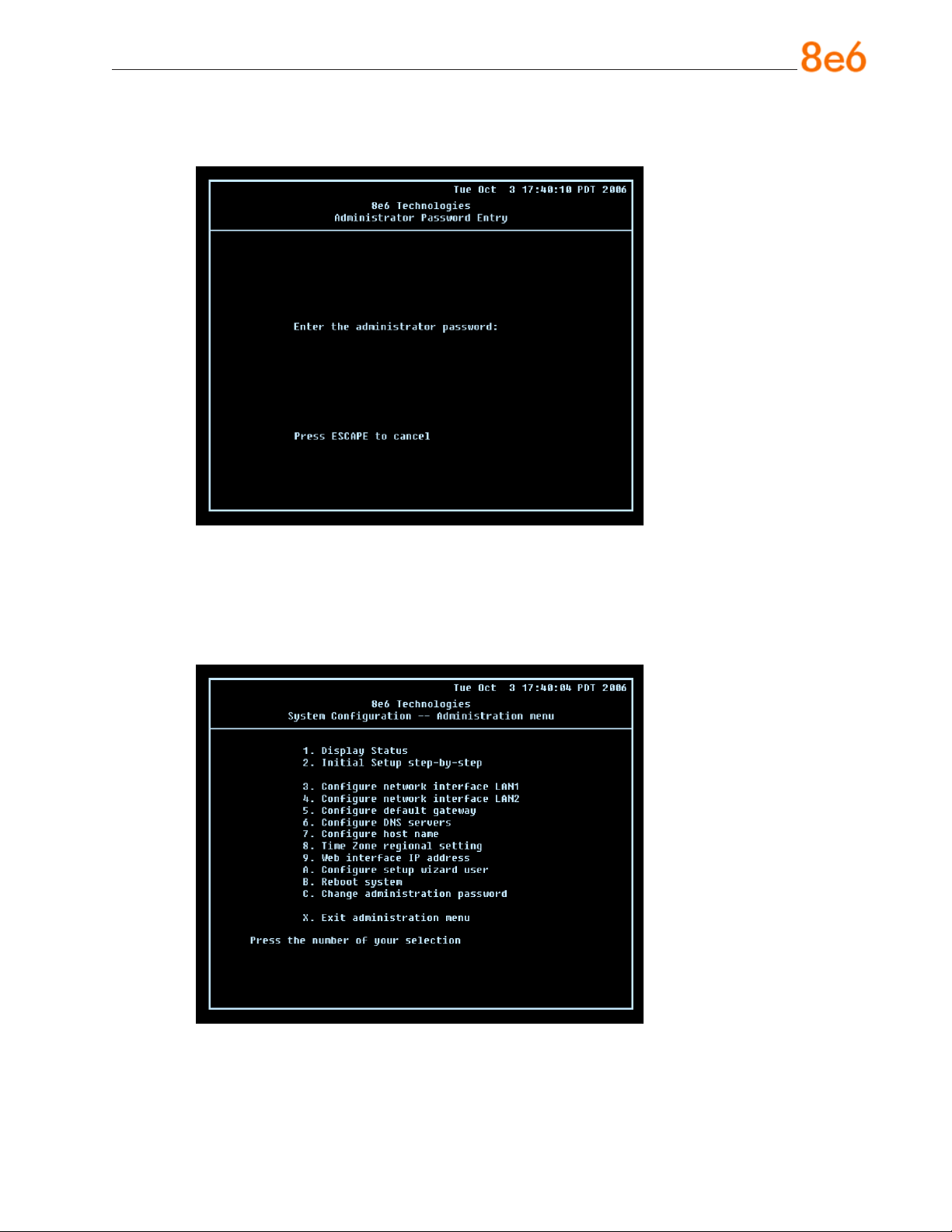
E. At the Press the number of your selection prompt, press 2 to display the Adminis-
trator Password Entry screen:
F. At the Enter the administrator password prompt, re-enter your password:
#s3tup#r3k
G. Press Enter to display the Administration menu where you can begin the step-by-
step initial setup process using the conguration screens:
H. At the Press the number of your selection prompt, press 2 to select the “Initial
Setup step-by-step” process. This process takes you to the Congure Network Interface screen.
8e6 ThreaT analysis reporTer Quick sTarT Guide 25
Page 30
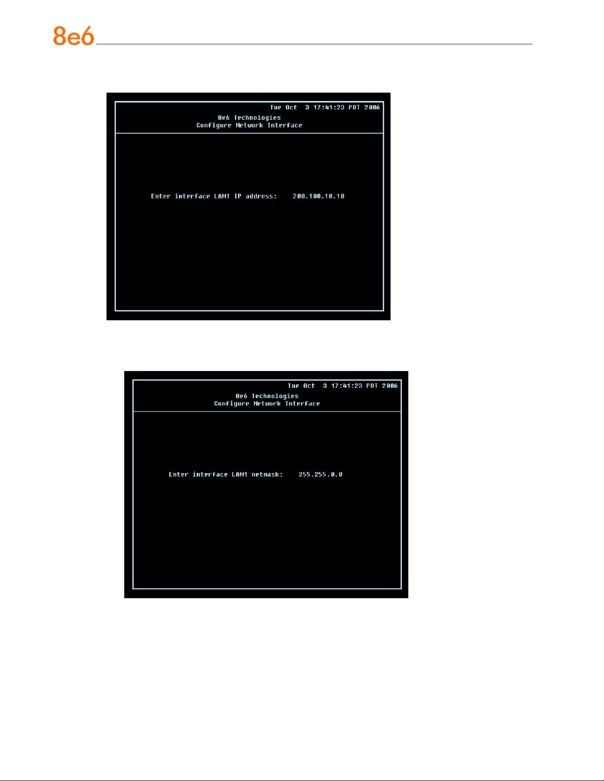
Congure Network Interface screen
A. At the Enter interface LAN1 (eth0) IP address eld, enter the IP address for the
LAN 1 (Ethernet 0) interface, and then press Enter to go to the next screen.
B. At the Enter interface LAN1 (eth0) netmask eld, enter the subnet mask for the
LAN 1 (Ethernet 0) interface using the dotted decimals notation format. Press Enter
to display the conrmation prompt.
26 8e6 ThreaT analysis reporTer Quick sTarT Guide
Page 31
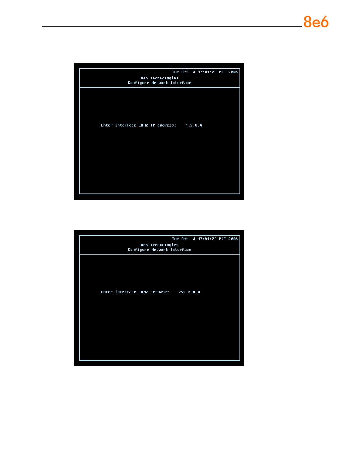
C. Press Y for “Yes” to conrm and save your entries for the LAN1 (eth0) interface, and
to go to the next screen.
D. At the Enter interface LAN2 (eth1) IP address eld, enter the IP address for the
LAN 2 (Ethernet 1) interface, and then press Enter to go to the next screen.
E. At the Enter interface LAN2 (eth1) netmask eld, using the dotted decimals nota-
tion format, enter the subnet mask for the LAN 2 (Ethernet 1) interface. Press Enter
to display the conrmation prompt.
F. Press Y for “Yes” to conrm and save your entries for the eth1 interface, and to go to
the Congure default gateway screen.
8e6 ThreaT analysis reporTer Quick sTarT Guide 27
Page 32
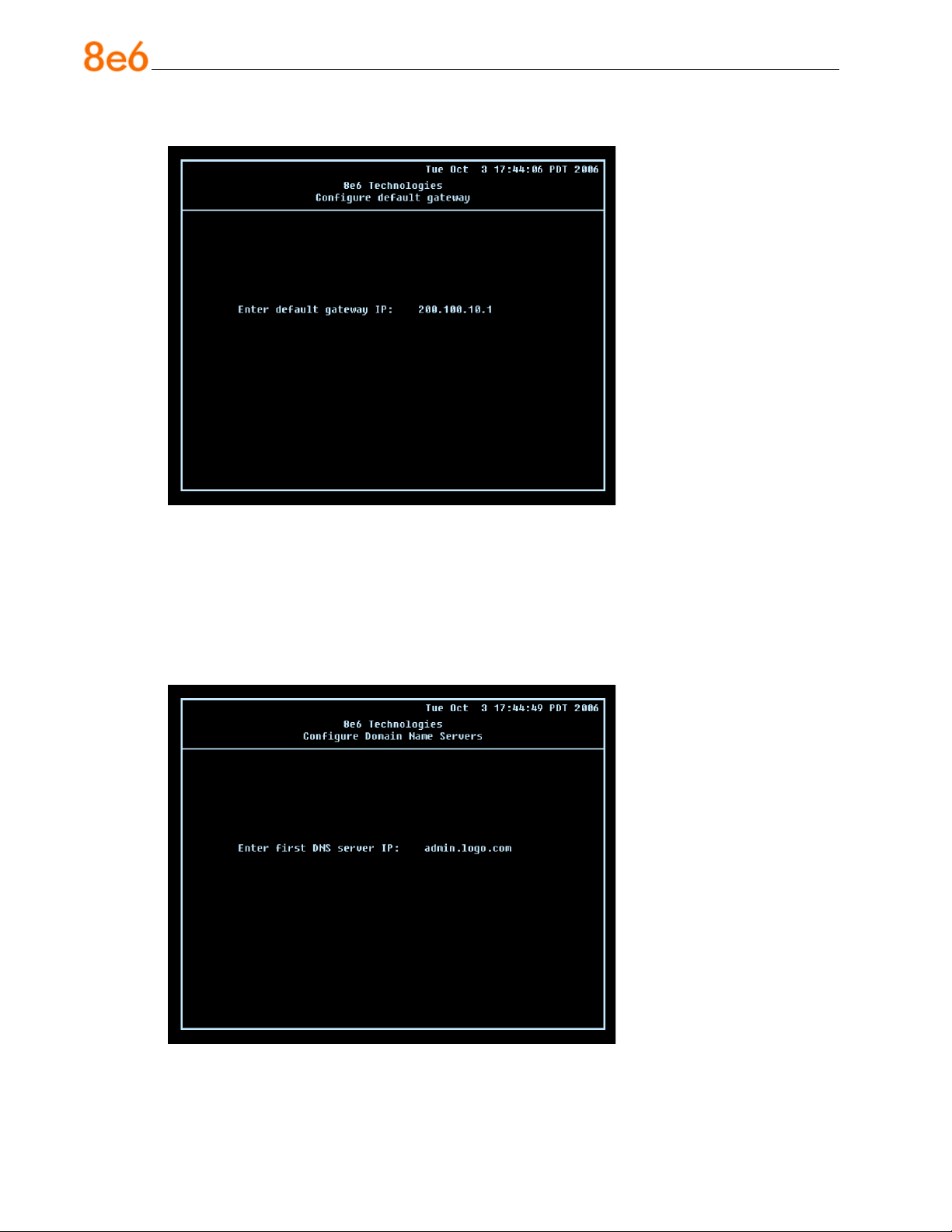
Congure default gateway screen
A. At the Enter default gateway IP eld, enter the IP address for the default gateway.
Press Enter to display the conrmation prompt.
B. Press Y for “Yes” to conrm and save your entry for the gateway IP address, and to
go to the Congure Domain Name Servers screen.
Congure Domain Name Servers screen
28 8e6 ThreaT analysis reporTer Quick sTarT Guide
Page 33
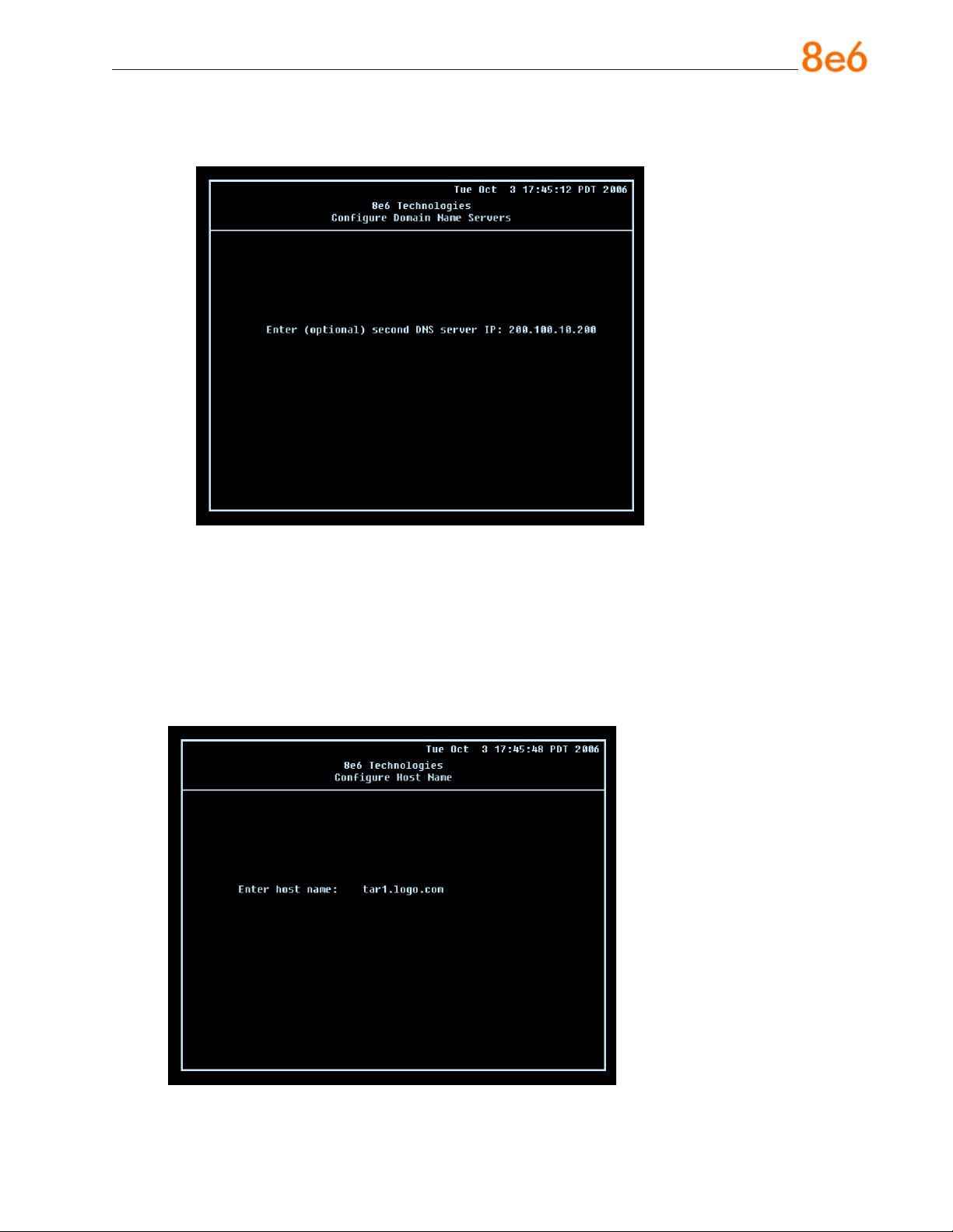
A. At the Enter rst DNS server IP eld, enter the IP address for the primary Domain
Name Server. Press Enter to go to the next screen.
B. At the Enter (optional) second DNS server IP eld, if you have a secondary Do-
main Name Server you wish to use, enter the IP address for that server. Press Enter
to display the conrmation prompt.
C. Press Y for “Yes” to conrm and save your entries for the domain name servers, and
to go to the Congure Host Name screen.
Congure Host Name screen
8e6 ThreaT analysis reporTer Quick sTarT Guide 29
Page 34
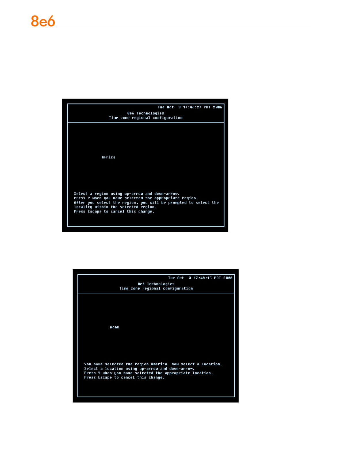
A. At the Enter host name eld, enter the host name of the server. Press Enter to dis-
play the conrmation prompt.
B. Press Y for “Yes” to conrm and save your entry for the host name, and to go to the
Time zone regional conguration screen.
Time zone regional conguration screen
A. Use the up and down arrows in your keyboard to select your region. After selecting
your locality, press Y for “Yes” to conrm and save your regional selection, and to go
to the next screen:
30 8e6 ThreaT analysis reporTer Quick sTarT Guide
Page 35
B. Use the up and down arrows in your keyboard to select your region. After selecting
your locality, press Y for “Yes” to conrm and save your regional selection, and to go
to the Congure Wizard user screen.
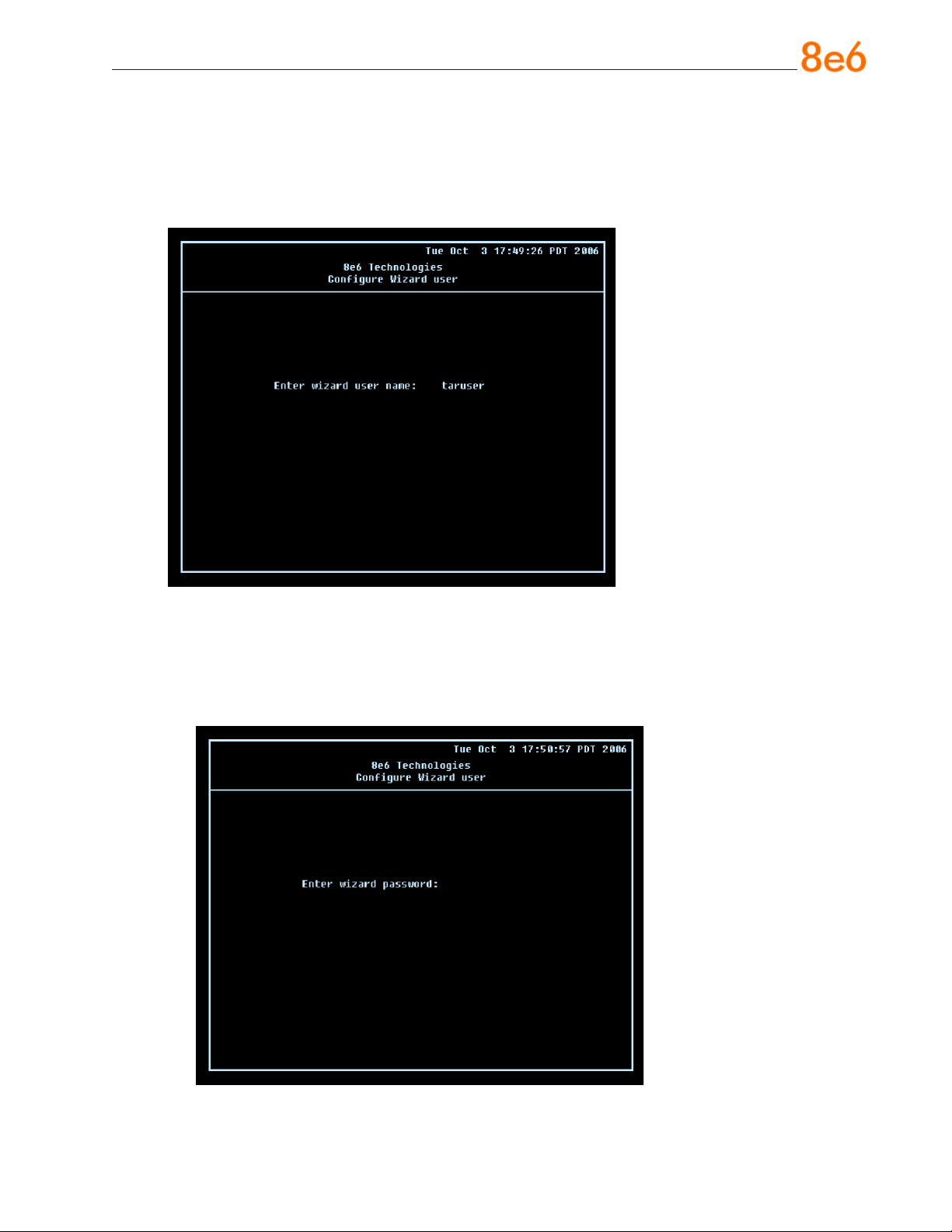
Congure Wizard user screen
A. At the Enter wizard user name eld, enter the username that will be used to access
the setup wizard in the Threat Analysis Reporter interface. Press Enter to display the
conrmation prompt.
B. Press Y for “Yes” to conrm and save your entry and to go to the next screen.
8e6 ThreaT analysis reporTer Quick sTarT Guide 31
Page 36
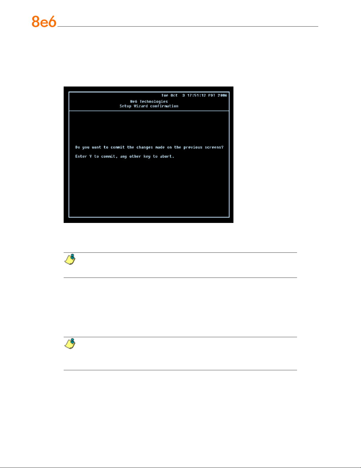
C. At the Enter wizard password eld, enter the password that will be used to access
the setup wizard in the Threat Analysis Reporter interface. Press Y for “Yes” to con-
rm and save your entry and to go to the Setup Wizard Conrmation screen.
Setup Wizard Conrmation screen
Press Y for “Yes” to save all your wizard entries and to return to the Administration
menu.
NOTE: When saving your entries, there may be a 4-10 second delay before
the Administration menu displays.
Administration menu
After making all entries using the step-by-step initial setup process, you will return to the
Administration menu. Press X to return to the System Conguration screen. Or, to verify
the status of the Threat Analysis Reporter and review the entries you made using the
wizard, press 1 to view the System Status screen.
NOTE: Changing your password using option C, “Change administration password”, will change the password for the console menu but not the Threat Analysis
Reporter console login screen.
32 8e6 ThreaT analysis reporTer Quick sTarT Guide
Page 37
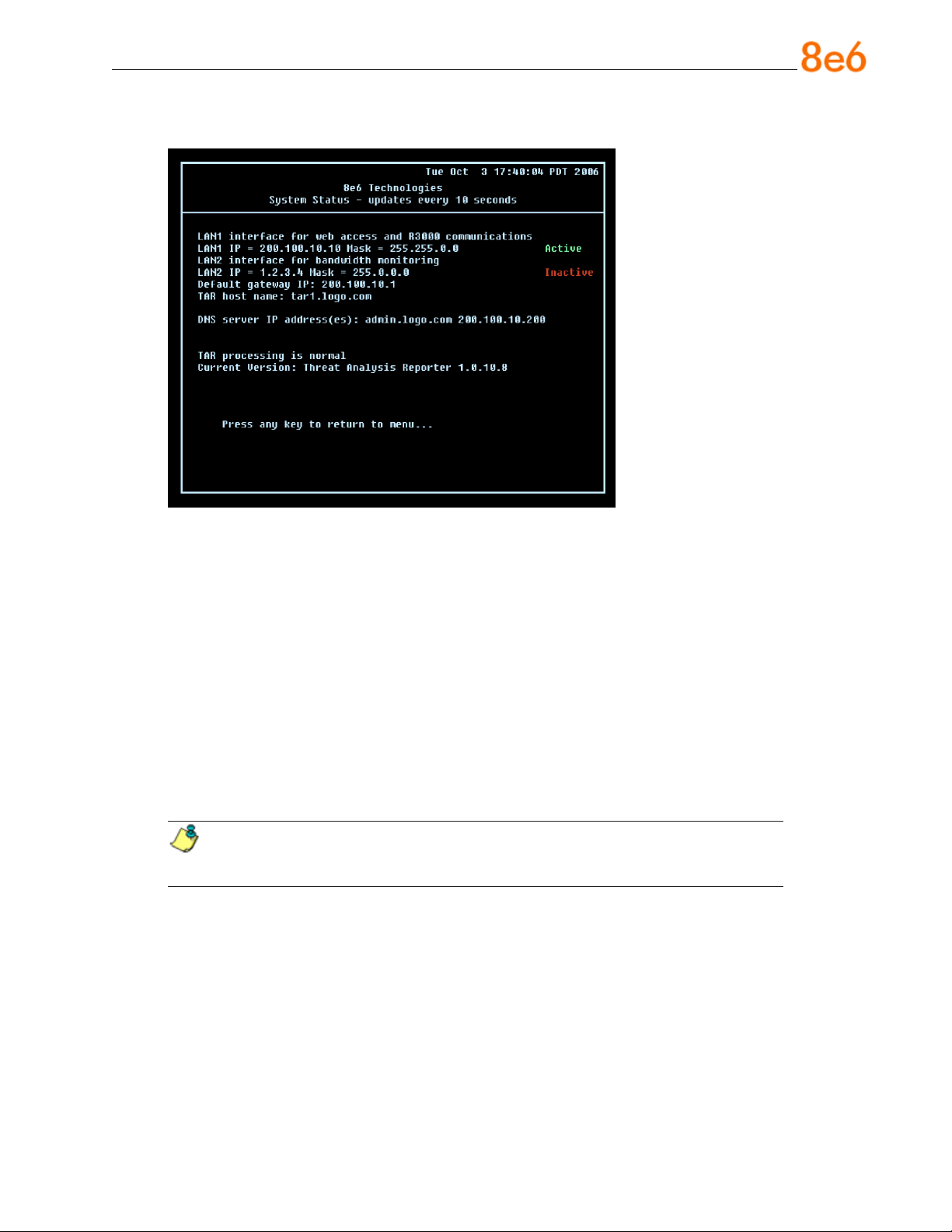
System Status Screen
The System Status screen contains the following information:
LAN1 (eth0) interface for web access and R3000 communications: LAN1 (eth0)
•
IP address and netmask specied in screen 3 (Congure Network Interface), and
current status (“Active” or “Inactive”)
LAN2 (eth1) interface for bandwidth monitoring: LAN2 (eth1) IP address and
•
netmask specied in screen 4 (Congure Network Interface), and current status
(“Active” or “Inactive”)
Default gateway IP address specied in screen 5 (Congure default gateway)
•
Congure host name specied in screen 7 (Congure Host Name)
•
DNS server IP address(es) specied in screen 6 (Congure Domain Name Servers)
•
Current status of the Threat Analysis Reporter
•
Current Version of the Threat Analysis Reporter software
•
NOTE: Modications can be made at any time by returning to the specic
screen of the wizard.
Log Off, Disconnect the Peripherals
A. After completing the wizard setup procedures, return to the System Conguration
screen and press 9 to log out.
B. Disconnect the peripherals from the Threat Analysis Reporter.
C. Proceed to Physically Connect the Unit to the Network.
8e6 ThreaT analysis reporTer Quick sTarT Guide 33
Page 38
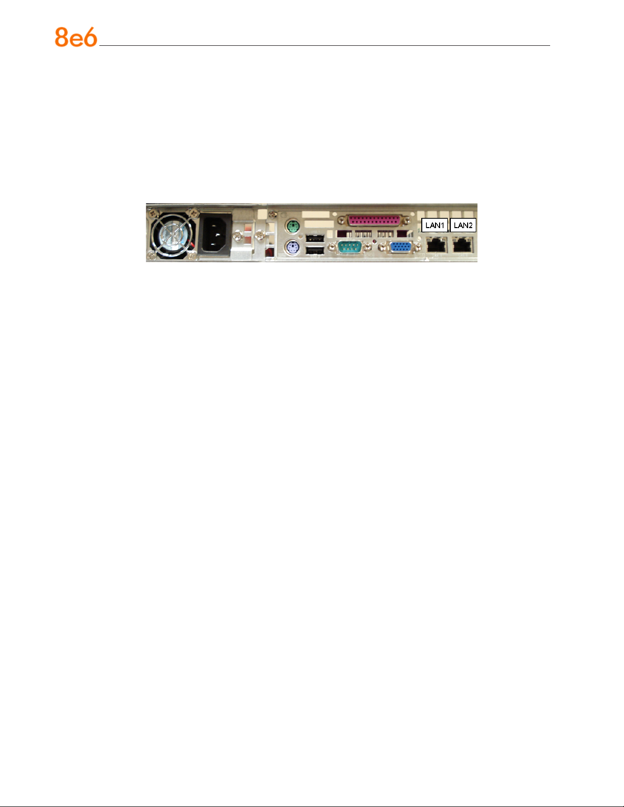
Physically Connect the Unit to the Network
After performing initial setup procedures for the Threat Analysis Reporter, the unit should
be physically connected to the network. This step requires a standard CAT-5E cable to
connect the unit to the network. An additional CAT-5E cable is required if the Ethernet
Tap unit will be installed for bandwidth monitoring.
A. Plug one end of a standard CAT-5E cable into the Threat Analysis Reporter’s LAN 1
port, the port on the left.
Portion of chassis rear
B. Plug the other end of the CAT-5E cable into an open port on the network switch.
Bandwidth Management
If you choose to install the Ethernet Tap for bandwidth monitoring, you will need to connect it to the Threat Analysis Reporter at this point. Refer to Appendix A at the end of this
document for instructions on how to connect the Ethernet Tap unit.
34 8e6 ThreaT analysis reporTer Quick sTarT Guide
Page 39
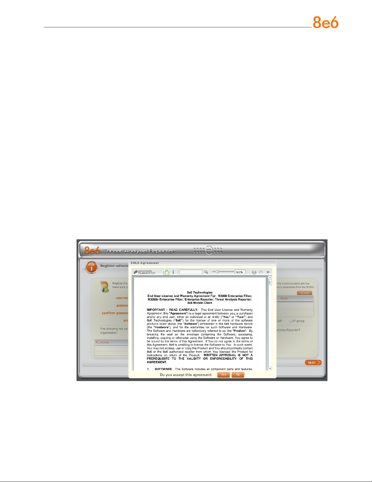
Step 2: Wizard Setup Procedures
For this step, you will need your network administrator to provide you the following information:
IP range and netmask of machines on the network the Threat Analysis Reporter
•
server will be monitoring
R3000 IP address, port number to be used between the R3000 and Threat Analysis
•
Reporter, and type of authentication method to be used (IP group or LDAP)
8e6 Enterprise Reporter server IP address and server name, if an ER unit is con-
•
nected to the R3000
Access the Threat Analysis Reporter Administrator Console
A. Launch Internet Explorer.
B. In the address eld, type in http://x.x.x.x:8080/8e6tar/wizard.html (in which “x.x.x.x”
represents the eth0 IP address entered in the Connect Network Interface screen
of the Step-by-Step Initial Setup Procedures). In our example, this entry would be:
http://200.100.10.10:8080/8e6tar/wizard.html.
C. Click Go to open the Threat Analysis Reporter interface and the EULA Agreement
dialog box:
8e6 ThreaT analysis reporTer Quick sTarT Guide 35
Page 40
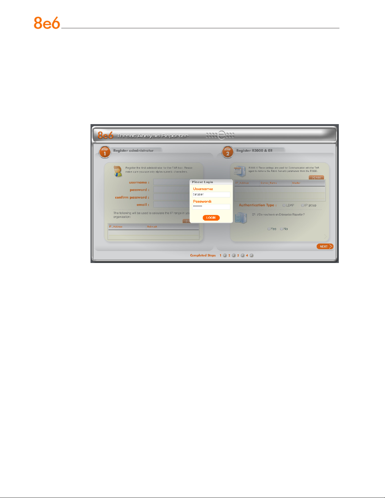
D. After reading the End User License Agreement, you have the option to do either of
the following:
Click No to close both the EULA Agreement dialog box and the Threat Analysis
•
Reporter interface. You will not be able to enable the Threat Analysis Reporter for
use in your environment.
Click Yes to close the EULA Agreement dialog box and to open the Login dialog
•
box:
Proceed to the next sub-section: Log in to the Threat Analysis Reporter Adminis-
trator Console.
Log in to the Threat Analysis Reporter Administrator Console
A. In the Username eld of the Login dialog box, type in the username specied in the
Congure Wizard user screen of the Step-by-Step Initial Setup Procedures. In our
example, this entry would be: taruser.
B. In the Password eld, type in the password specied in the Congure Wizard user
screen of the Step-by-Step Initial Setup Procedures.
C. Click LOGIN to close the login dialog box and to go to Step 1 of wizard setup pro-
cedures in the Threat Analysis Reporter Administrator console (see Step 1: Register
administrator).
36 8e6 ThreaT analysis reporTer Quick sTarT Guide
Page 41
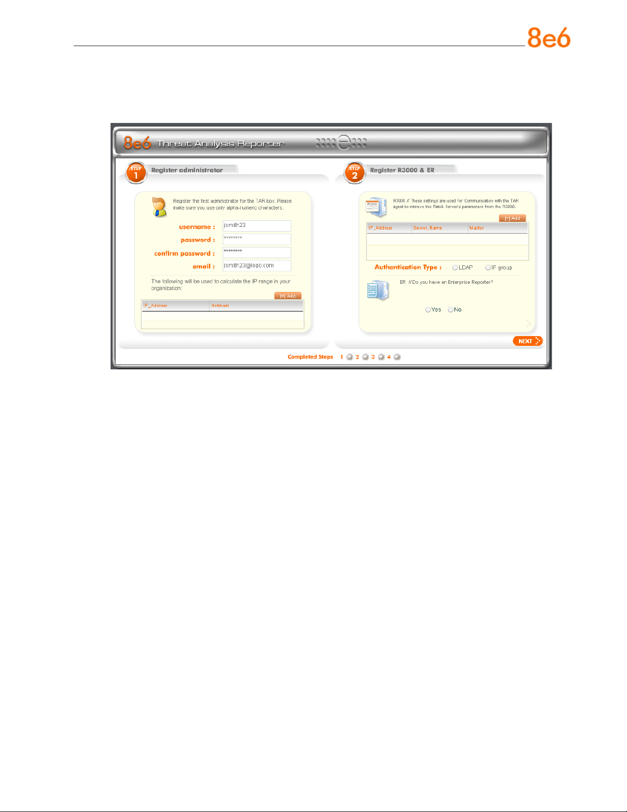
Step 1: Register administrator
Step 1 is performed in the left side of the rst screen of the wizard:
A. Enter the username the global administrator will use when logging into the Threat
Analysis Reporter Administrator console. The global administrator has the highest
level of permissions in the Threat Analysis Reporter interface.
B. Enter the password to be used with that username, and enter the same password
again in the conrm password eld.
C. Enter the email address of the global administrator, who will be notied via email
when gauges reach their specied upper threshold limits.
8e6 ThreaT analysis reporTer Quick sTarT Guide 37
Page 42
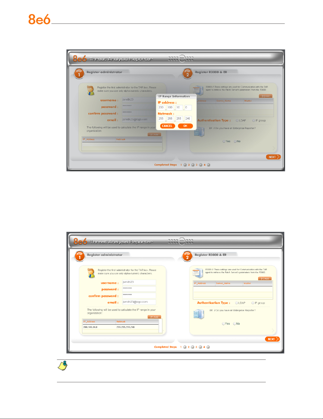
D. Click the [+] Add tab beow to open the IP Range Information dialog box:
E. Enter the IP address range for the bandwidth the Threat Analysis Reporter will moni-
tor.
F. Enter the Netmask for the IP range to be monitored, using the dotted decimals nota-
tion format.
G. Click OK to close the dialog box and to display your entries in the list box:
NOTE: Additional IP address ranges can be included by clicking the [+] Add
tab again and making the entries described in steps E through G above.
38 8e6 ThreaT analysis reporTer Quick sTarT Guide
Page 43
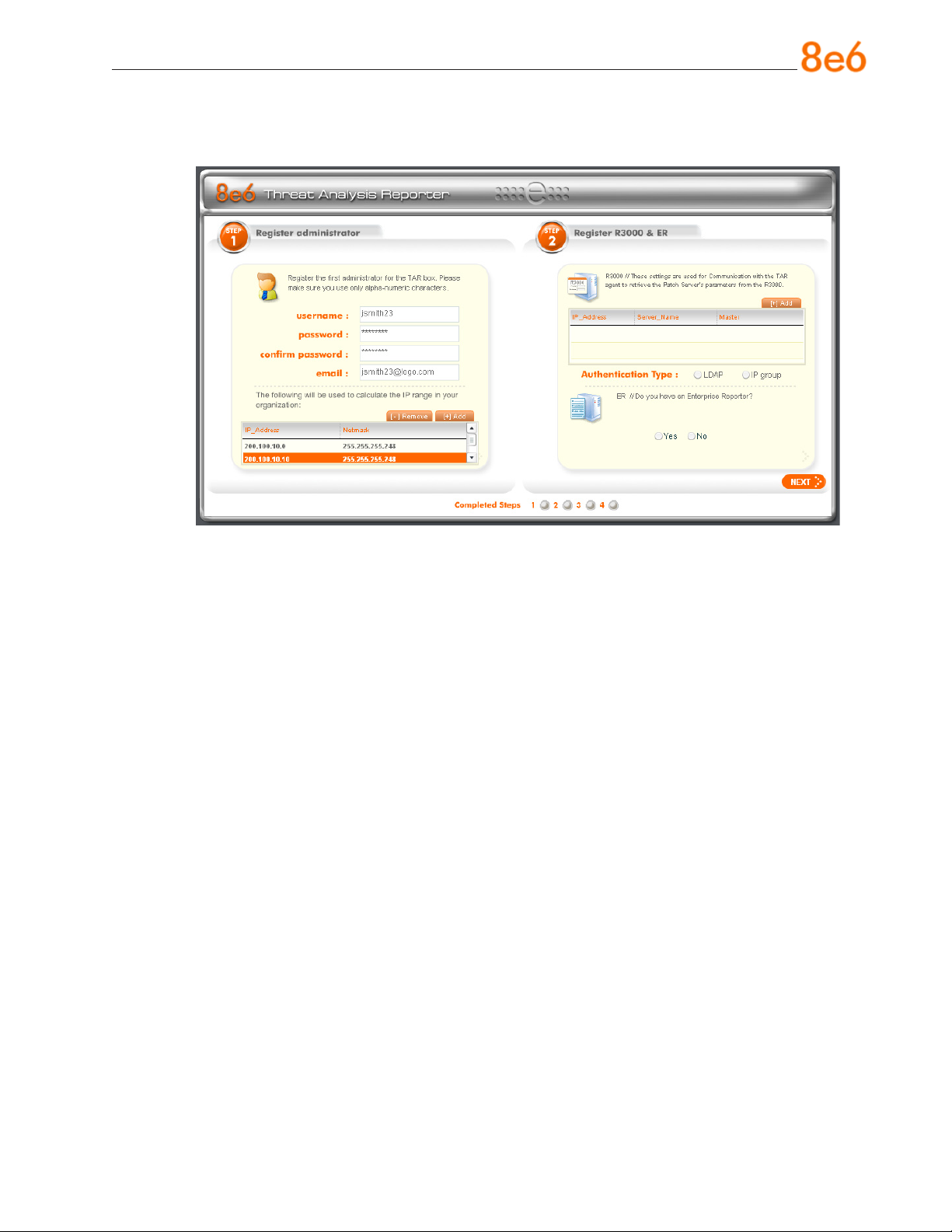
To modify an IP address range, double-click the entry in the list box to highlight it and
to display the [-] Remove tab to the left of the [+] Add tab:
To modify the entries made for the IP address range, click the [+] Add tab to re-
•
open the IP Range Information dialog box and edit information, as necessary.
Click OK to close the dialog box and to display the modied information in the list
box.
To remove the entry for the IP address range from the list box, click the [-] Re-
•
move tab. Click the [+] Add tab to open the IP Range Information dialog box and
make new entries for the IP address range.
8e6 ThreaT analysis reporTer Quick sTarT Guide 39
Page 44
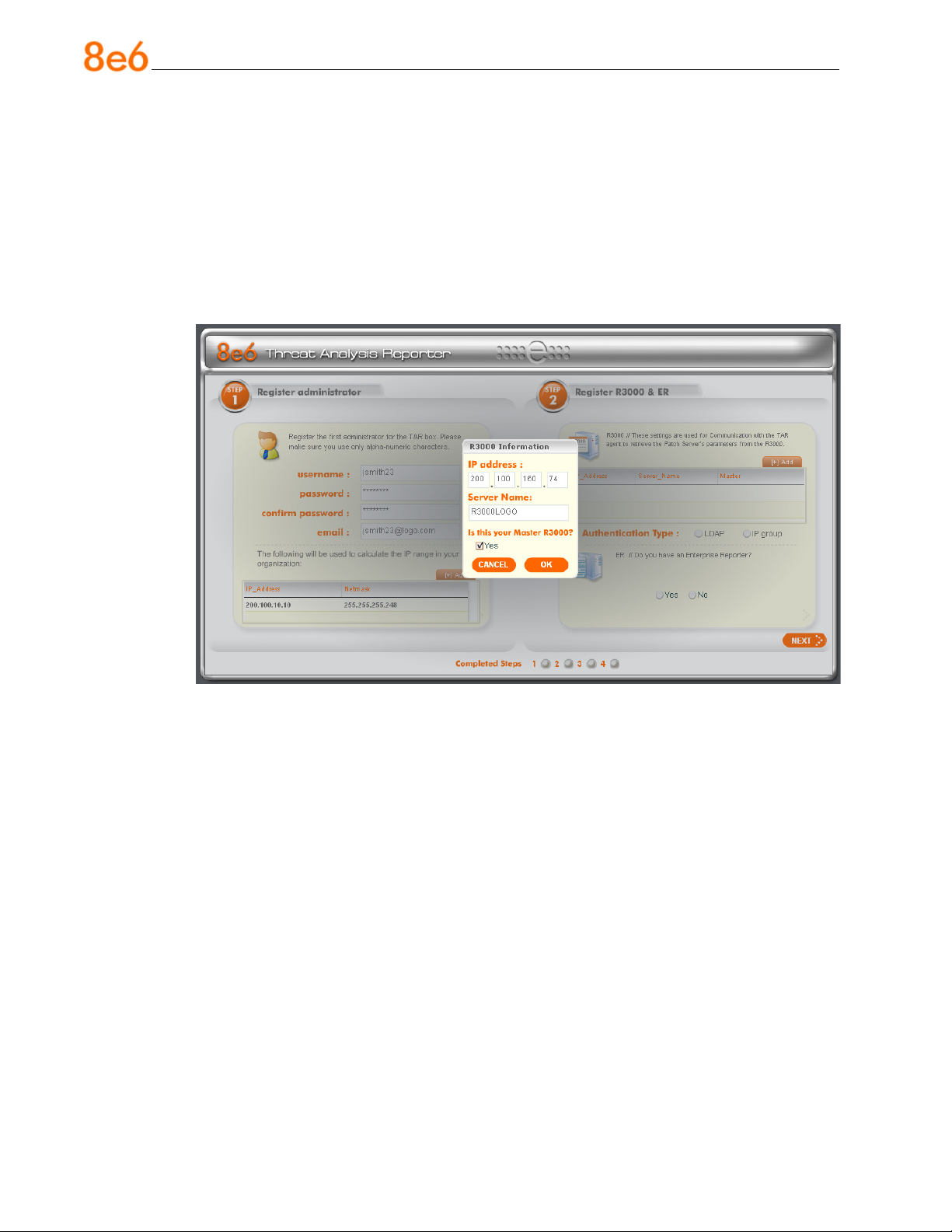
Step 2: Register R3000 & ER
Step 2 is performed in the right side of the rst screen of the wizard.
R3000:
Specify information for the R3000 to be used with the Threat Analysis Reporter:
A. Click the [+] Add tab above the R3000 list box to open the R3000 Information dialog
box:
B. Enter the IP address of the R3000 server to be used with the Threat Analysis Re-
porter. In our example, this is: 200.100.160.74, which is the Ethernet 1 IP address of
the R3000 server.
C. Enter the Server Name of the R3000 to be used with the Threat Analysis Reporter,
which is any name you wish to associate with that R3000. In our example, this is:
R3000LOGO.
D. Respond to the question “Is this your Master R3000?” by clicking the “Yes” checkbox,
if this R3000 will be designated the master R3000 to be associated with the Threat
Analysis Reporter. Otherwise, leave the checkbox blank.
40 8e6 ThreaT analysis reporTer Quick sTarT Guide
Page 45
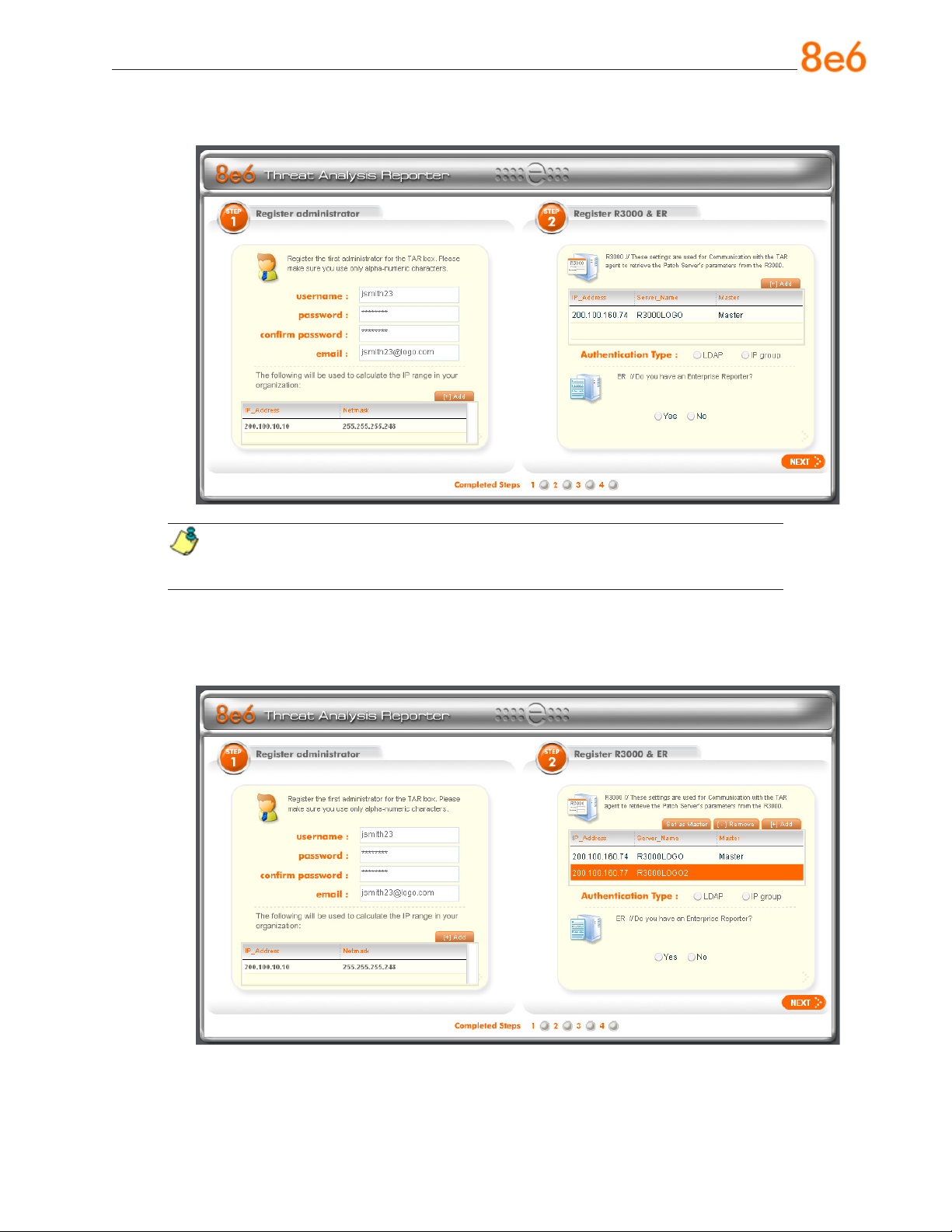
E. Click OK to close the dialog box and to display your entries in the list box:
NOTE: Additional R3000 servers can be included by clicking the [+] Add tab
again and making the entries described in steps A through E above.
To modify an R3000 entry, double-click the R3000 entry in the list box to highlight it
and to display the Set as Master tab and the [-] Remove tab to the left of the [+] Add
tab:
8e6 ThreaT analysis reporTer Quick sTarT Guide 41
Page 46
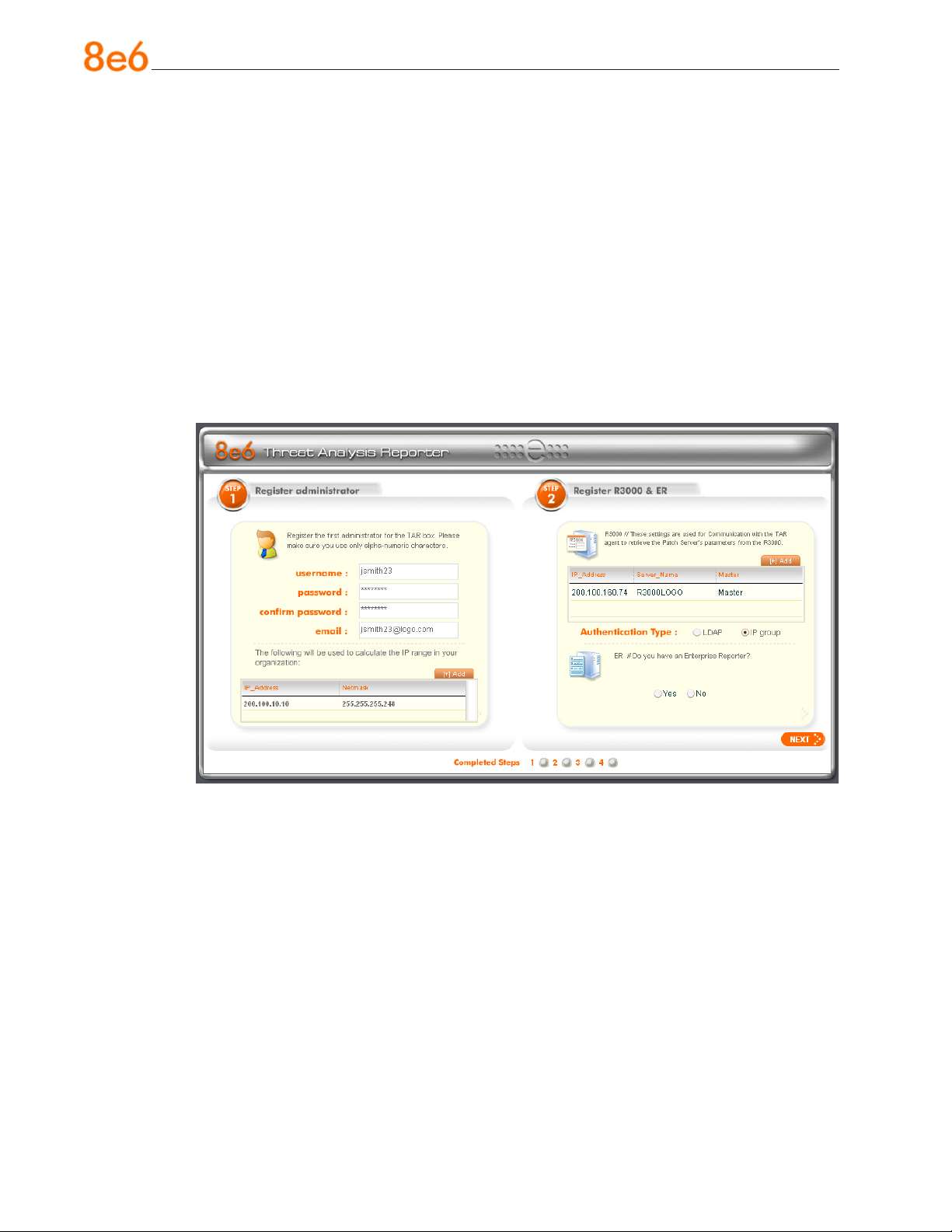
To modify the IP address and Server Name for the R3000 server, click the [+]
•
Add tab to re-open the R3000 Information dialog box, and edit information as
necessary. Click OK to close the dialog box and to display the modied information in the list box.
To designate an R3000 as the Master R3000 server, click the entry for the R3000
•
server in the list box to highlight it, and then click the Set as Master tab to display
“Master” in the Master column for that entry in the list box.
To remove the entry for the R3000 server from the list box, click the [-] Remove
•
tab.
F. Specify the User Authentication method to be used for monitoring activity on the
Threat Analysis Reporter server: “LDAP” or “IP group”:
42 8e6 ThreaT analysis reporTer Quick sTarT Guide
Page 47
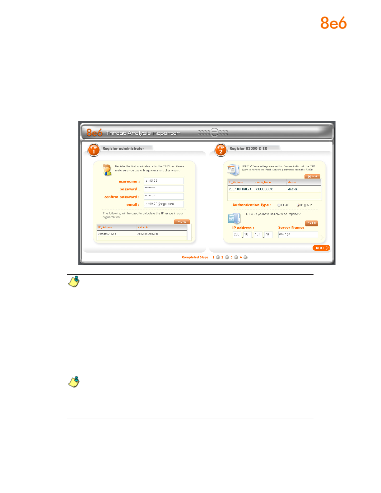
ER:
Respond to the question “Do you have an Enterprise Reporter?” by clicking the radio
button corresponding to either “Yes” or “No”.
If “No” was selected, click NEXT > at the bottom right of the screen to go to Step 3.
•
If “Yes” was selected, the IP address and Server Name elds display in place of the
•
radio buttons. The < Back button displays above the Server Name eld.
NOTE: To change your answer from “Yes” to “No,” click the < Back button to
re-display the question “Do you have an Enterprise Reporter?”
A. Enter the IP address of the ER server to be used with the Threat Analysis Re-
porter. In our example, this is: 200.10.101.76.
B. Enter the Server Name of the ER server to be used with the Threat Analysis
Reporter. In our example, this is: er4logo.
C. Click NEXT > at the bottom right of the screen to go to Step 3.
NOTE: Upon clicking NEXT > the wizard will verify whether the settings made
in Step 1 and Step 2 are correct. If there is an error in any entry made, an orange
asterisk ashes beside the eld in which the error was made. Correct the error and
click NEXT > again to go to Step 3.
8e6 ThreaT analysis reporTer Quick sTarT Guide 43
Page 48
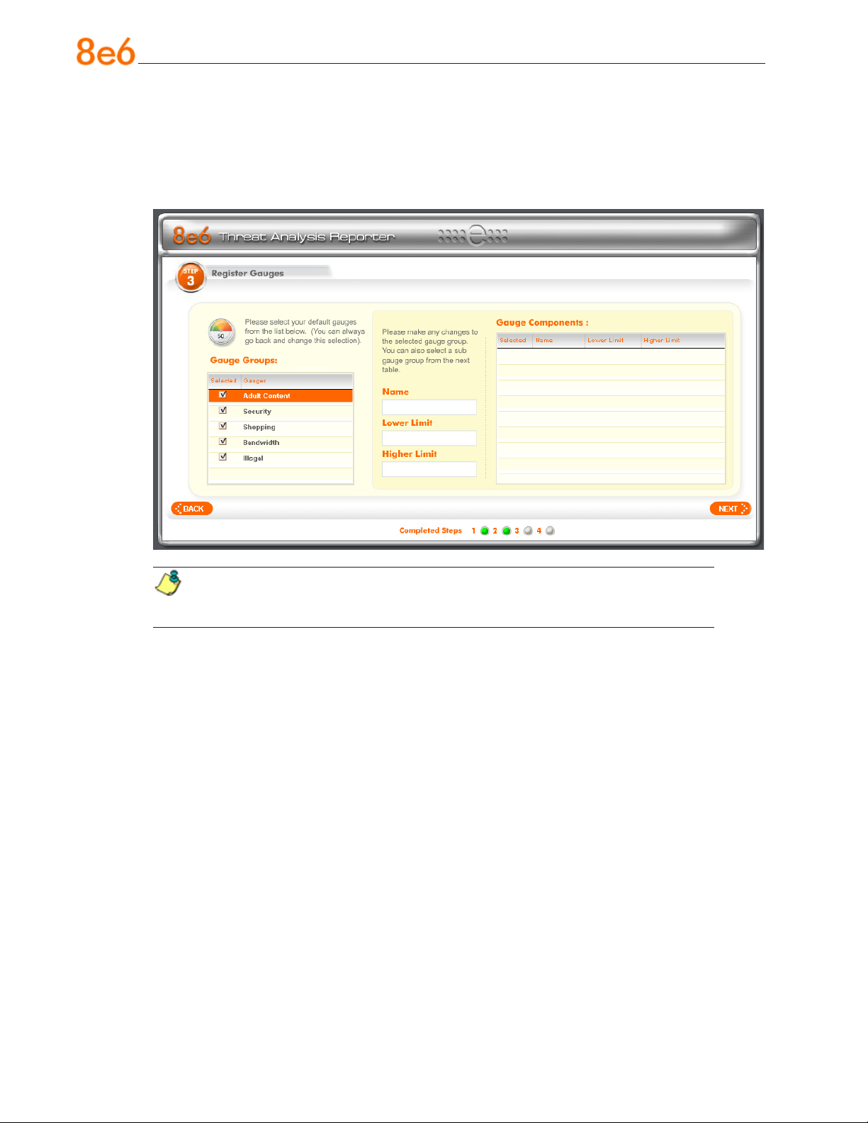
Step 3: Register Gauges
Step 3 requires you to specify settings for default gauges to be monitored by the Threat
Analysis Reporter. These gauges will display in the Threat Analysis Reporter interface
upon logging into the Administrator console.
NOTE: Return to Step 1 or Step 2 by clicking the < BACK button in the lower
left corner of this wizard screen.
Specify Gauge Groups to be Monitored
By default, all Gauges displayed in this wizard screen (Adult Content, Security, Shopping, Bandwidth, Illegal) are selected for monitoring. To deselect a gauge from the
Gauge Groups list, remove the checkmark by clicking the checkbox in the Selected
column corresponding to that gauge.
44 8e6 ThreaT analysis reporTer Quick sTarT Guide
Page 49
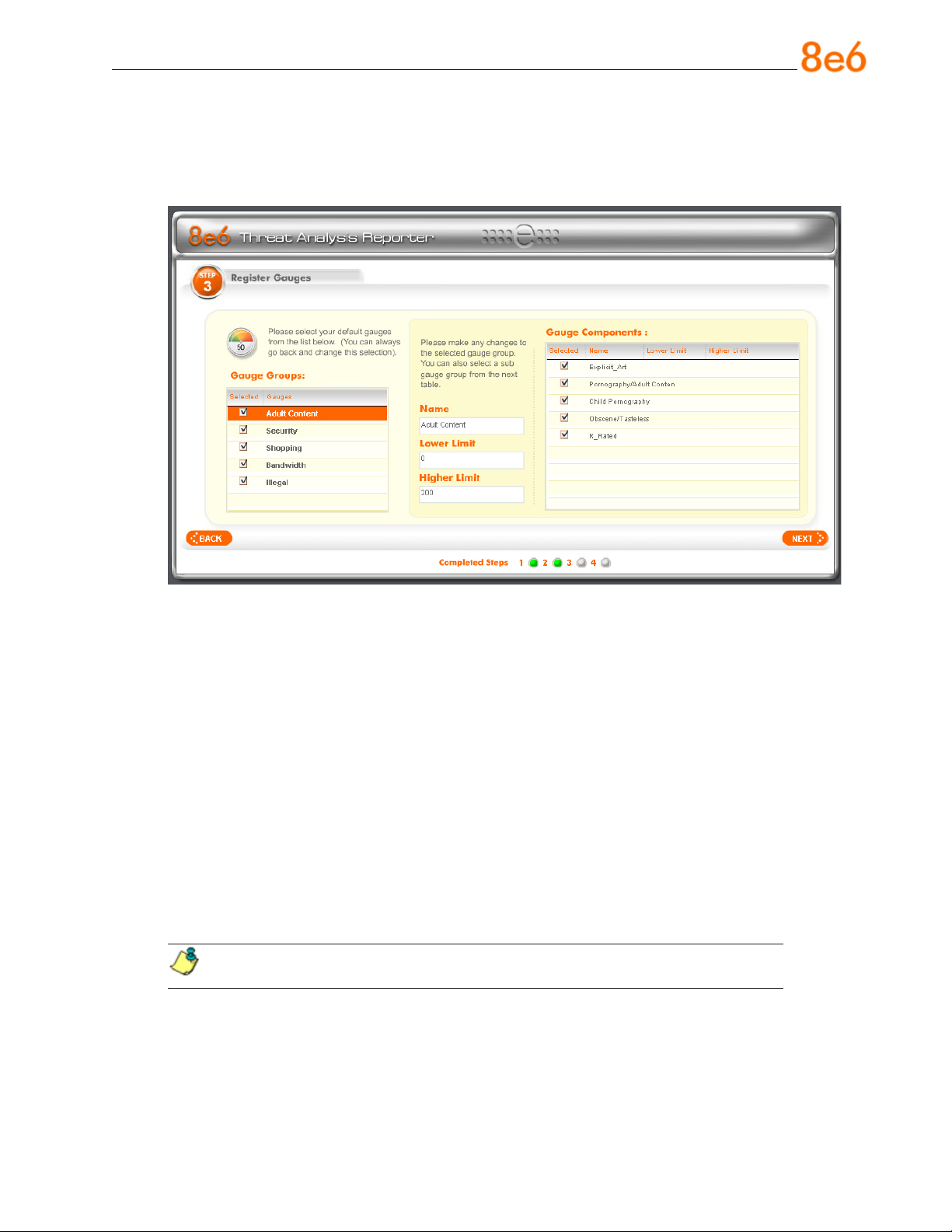
View, Edit Gauge Components
To view gauge components for a specied gauge, highlight and double-click the gauge
name to populate the the elds to the right of the Gauge Groups list box.
The following gauge criteria can be edited:
Name: The displayed gauge name to be used in the interface can be modied by
•
making an entry in this eld.
Lower Limit: The default amount (“0” or zero) that will represent the lower end of the
•
gauge can be adjusted to accommodate the type of activity to be monitored on your
network.
Higher Limit: The default amount (“200”) that will represent the higher end of the
•
gauge can be adjusted to accommodate the type of activity to be monitored on your
network.
Gauge Components: To remove a gauge component, go to the Selected column
•
and click the checkmark in the checkbox corresponding to the component to be
removed.
NOTE: The settings saved in this step can be modied later in the interface.
Click NEXT > at the bottom right of the screen to go to Step 4.
8e6 ThreaT analysis reporTer Quick sTarT Guide 45
Page 50
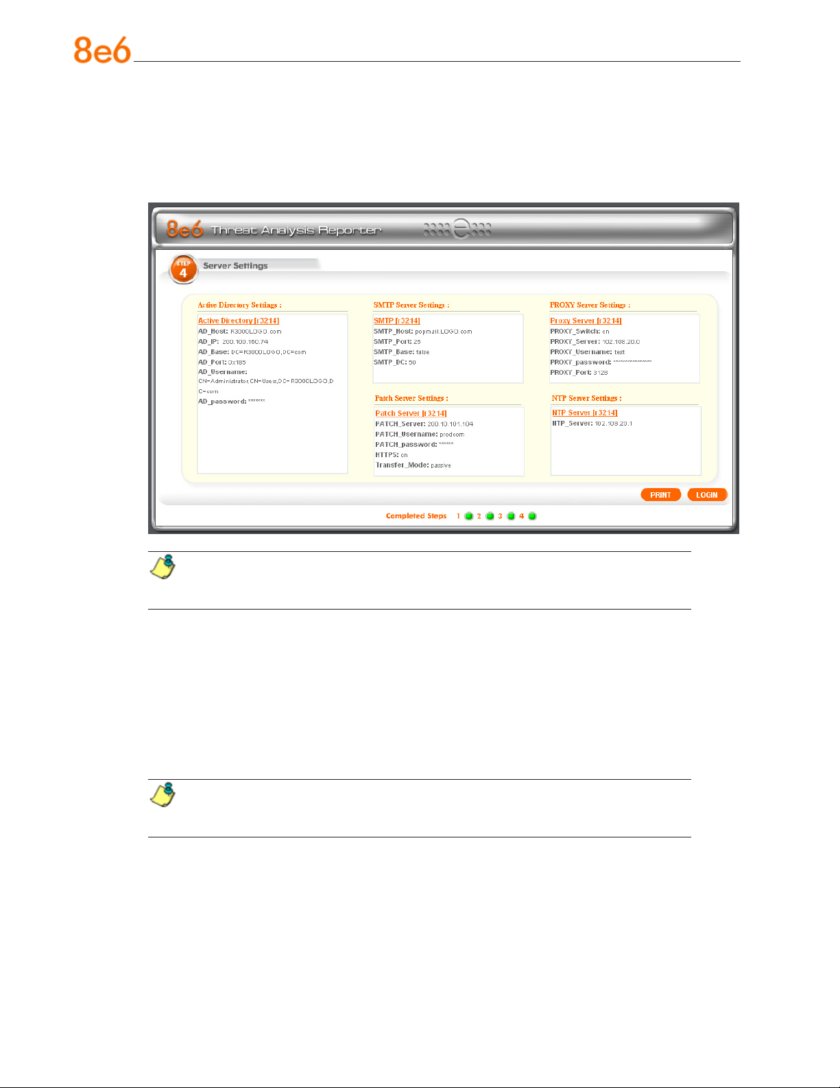
Step 4: Server Settings
In Step 4, the following R3000 server information displays: Active Directory Settings,
SMTP Server Settings, Patch Server Settings, PROXY Server Settings, NTP Server Settings:
NOTE: Return to Step 3 by clicking the < BACK button in the lower left corner
of this wizard screen.
After reviewing the information in this screen, the following actions can now be performed:
To print this information, click the Print button.
•
To save all settings entered during the wizard process, click Save. After your infor-
•
mation is saved, the login dialog box of the Threat Analysis Reporter interface displays, and you can begin using the application.
NOTE: To shut down the Threat Analysis Reporter server, press the power
button on the front of the unit to turn off the machine.
46 8e6 ThreaT analysis reporTer Quick sTarT Guide
Page 51

ConClusion
Congratulations; you have completed the Threat Analysis Reporter quick start procedures. Now that the Threat Analysis Reporter is running on your network, the next step
is to set up user groups or administrator groups. You will set up and congure gauges
thereafter.
Obtain the latest Threat Analysis Reporter User Guide from our Web site at http://
www.8e6.com/docs/tar_ug.pdf.
8e6 ThreaT analysis reporTer Quick sTarT Guide 47
Page 52
led indiCators and Buttons
MSA Units
Front LED Indicators and Buttons for Hardware Status Monitoring
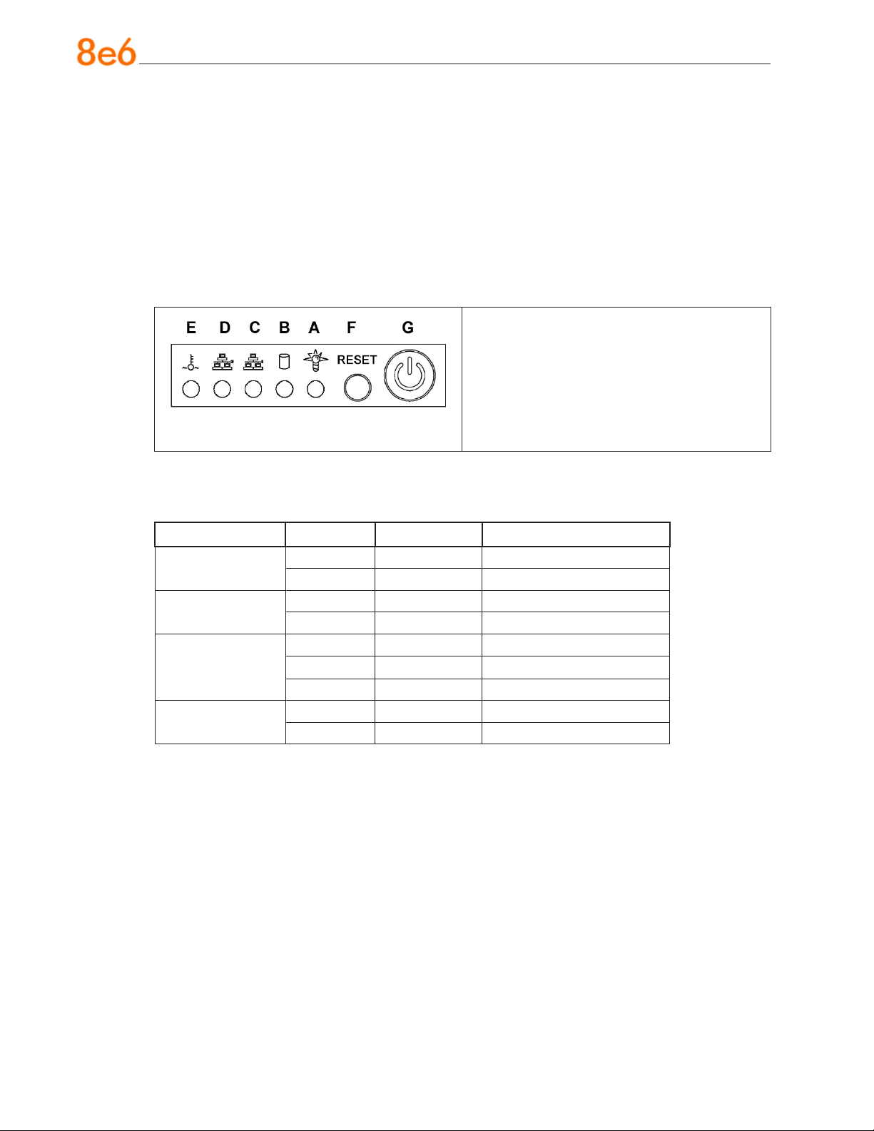
LED indicators and buttons for hardware status monitoring display on the front panel,
located on the right side of the chassis (see diagram below).
LED Indicator Key Button Key
A = Power F = Reset
B = HDD Activity G = Power
C = LAN 1
D = LAN 2
Chassis control panel
LED indicators alert you to the status of a feature on the unit while buttons let you perform a function on the unit.
LED Indicator Color Condition Description
Power Green On System On
Off System Off
HDD Amber Blinking HDD Activity
Off No HDD Activity
LAN 1 & LAN 2 Green On Link Connected
Blinking LAN Activity
Off Disconnected
Overheat Red On System Overheated
Off System Normal
E = Overheat
48 8e6 ThreaT analysis reporTer Quick sTarT Guide
Page 53
regulatory speCifiCations and disClaimers
Declaration of the Manufacturer or Importer
Safety Compliance
USA: UL 60950-1 2nd ed. 2007
Europe: Low Voltage Directive (LVD) 2006/95/EC to CB Scheme EN 60950: 2006
International: UL/CB to IEC 60950-1:2006
Electromagnetic Compatibility (EMC)
USA: FCC CFR 47 Part 15, Veried Class A Limit
Canada: IC ICES-003 Class A Limit
Europe: EMC Directive, 2004/108/EC & Low Voltage Directive (LVD) 2006/95/EC
Federal Communications Commission (FCC) Class A Notice (USA)
This equipment has been tested and found to comply with the limits for a Class A digital device, pursuant to part 15 of the FCC Rules. These limits are designed to provide
reasonable protection against harmful interference when the equipment is operated in a
commercial environment. This equipment generates, uses, and can radiate radio frequency energy and, if not installed and used in accordance with the instruction manual,
may cause harmful interference to radio communications. Operation of this equipment
in a residential area is likely to cause harmful interference in which case the user will be
required to correct the interference at his own expense.
FCC Declaration of Conformity
Model: MSA-004-004
Electromagnetic Compatibility Class A Notice
Industry Canada Equipment Standard for Digital Equipment (ICES-003)
8e6 ThreaT analysis reporTer Quick sTarT Guide 49
Page 54
EC Declaration of Conformity
European Community Directives Requirement (CE)
Declaration of Conformity
Manufacturer’s Name: 8e6 Technologies
Manufacturer’s Address: 828 W. Taft Avenue
Orange, CA 92865
Application of Council Directive(s): Low Voltage • 2006/95/EC
EMC • 2004/108/EC
Standard(s): Safety • EN60950: 2006
EMC • EN55022: 2006
• EN55024: 1998 +A2:2003
• EN61000-3-2: 2000
• EN61000-3-3: 2001
Product Name(s): Internet Appliance
Product Model Number(s): MSA-004-004
Year in which conformity is declared: 2008
All hardware components supplied in this unit’s
shipping carton are certied by our vendors to be
RoHS compliant.
I, the undersigned, hereby declare that the equipment specied above conforms to the
above Directive(s) and Standard(s).
Location: Orange, CA, USA Signature:
Date: January 21, 2008 Full Name: Gregory P. Smith
Position: Director of Engineering Operations
50 8e6 ThreaT analysis reporTer Quick sTarT Guide
Page 55

tap installation
appendix: optional ethernet tap installation
This appendix pertains to the optional installation of the Ethernet Tap unit for bandwidth
monitoring.
Preliminary Setup Procedures
Unpack the Ethernet Tap Unit from the Box
Open the NetOptics Ethernet Tap box and verify that all accessories are included. Save
all packing materials in the event that the unit needs to be returned to 8e6 Technologies.
The NetOptics box should contain the following items:
1 NetOptics 10/100BaseT Tap
•
2 Power Supply units
•
2 AC Power cords
•
2 Crossover cables
•
2 Straight through cables
•
1 Installation Guide
•
Other Required Installation Items
In addition to the contents of the NetOptics box, you will need the following item to install
the Ethernet Tap unit:
1 Standard CAT-5E cable
•
Inspect the box for damage. If the contents appear damaged, le a damage claim with
the carrier immediately.
8e6 ThreaT analysis reporTer Quick sTarT Guide 51
Page 56
tap installation
Install the Ethernet Tap Unit
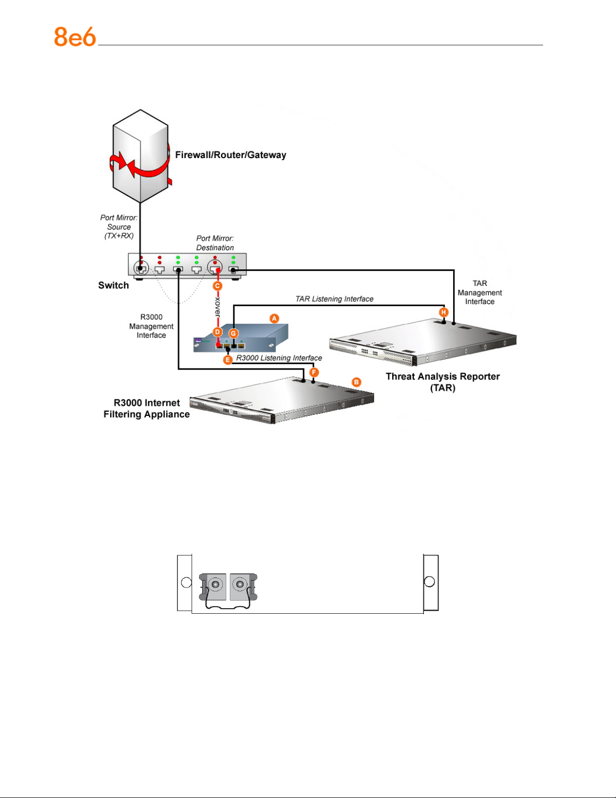
Diagram showing TAR Ethernet Tap installation on the network
This step is a continuation from Physically Connect the Unit to the Network in Step 1A
or following setup in Step 1B. The procedures outlined in this step require the use of a
CAT-5E cable.
A. Provide power to the Ethernet Tap by connecting both power cords from the unit to
the power source.
AC power in rear panel of NetOptics 10/100BaseT Tap
B. If a designated source R3000 (to be used with the Threat Analysis Reporter) is al-
ready installed on the network, disconnect the cable that connects this R3000 to the
switch.
If the designated R3000 has not yet been installed, disregard this sub-step and pro-
ceed to sub-step C.
52 8e6 ThreaT analysis reporTer Quick sTarT Guide
Page 57
tap installation
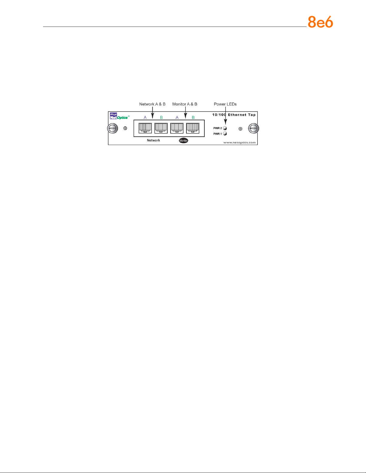
C. Using a crossover cable, connect one end to the Switch’s port congured to be the
destination port of the Port Mirror.
If adding a Threat Analysis Reporter to an existing installation, this port would be the
port that was originally occupied by the listening interface of the R3000.
D. Connect the other end of the crossover cable to the Ethernet Tap’s Network A port.
Ports in front panel of NetOptics 10/100BaseT Tap
E. Using a straight through cable, connect one end to the Ethernet Tap’s Network B
port.
F. Connect the other end of the straight through cable to the R3000’s listening interface.
G. Using the second straight through cable, connect one end to the Ethernet Tap’s
Monitor A port.
H. Connect the other end of the second straight through cable to the Threat Analysis
Reporter’s listening interface.
Proceed to Step 2: Wizard Setup Procedures of the Threat Analysis Reporter installation
instructions.
8e6 ThreaT analysis reporTer Quick sTarT Guide 53
Page 58

index
C
crossover cable 51, 53
E
EMC 49, 50
F
FCC 49
H
HyperTerminal Setup 21
I
ICES-003 49
Install TAP 51
L
Login screen 24
LVD 49
M
MSA 20, 48, 50
P
Power Supply Precautions 15
R
R3000 1, 19, 35, 40, 41, 42, 46, 52, 53
Rack Setup Precautions 6
RoHS compliant 50
S
serial port cable 19, 20
U
UL 49
54 8e6 ThreaT analysis reporTer Quick sTarT Guide
Page 59

8e6 Corporate Headquarters (USA):
828 West Taft Avenue Orange, CA 92865-4232 • Tel: 714.282.6111 or 888.786.7999
Fax: 714.282.6116 (Sales/Technical Support) • 714.282.6117 (General Ofce)
Satellite Ofce:
8e6 Taiwan: 7 Fl., No. 1, Sec. 2, Ren-Ai Rd., Taipei 10055, Taiwan, R.O.C.
Tel: 886-2-2397-0300 • Fax: 886-2-2397-0306
 Loading...