

Arecont Vision MDD-WMT, AV10655DN-08, AV10655DN-28, AV10655DN-NL, AV6655DN-08 Installation Manual
...Page 1

MicroDome® Duo
4 Megapixel
AV4655DN-08
AV4655DN-28
AV4655DN-NL
4 Megapixel WDR
AV4656 DN-08
AV4656DN -28
AV4656DN-NL
AV6655DN-08
AV6655DN-28
AV6655DN-NL
6 Megapixel WDR
AV6656DN-08
AV6656DN-28
AV6656DN-NL
AV10655DN-08
AV10655DN-28
AV10655DN-NL
Installation Manual
Models:
6 Megapixel
10 Megapixel
Page 2

Microdome Duo® Installation Manual
Contents
Models ................................................................................................................................................... 1
Package Content ................................................................................................................................... 3
Warranty Information ............................................................................................................................. 4
Camera Overview .................................................................................................................................. 5
Surface Installation ................................................................................................................................ 6
Drop Ceiling Mount Adapter Plate Installation ........................................................................................ 8
MDD-CAP Installation ............................................................................................................................ 9
MDD-CMT/WMT Pendant Mount and Wall Mount Installation...............................................................10
MDD-FMA Flush Mount Installation ......................................................................................................11
Pan and Tilt Adjustment ........................................................................................................................14
Lens Replacement ................................................................................................................................15
Usage of Ethernet cable other than included M/F PoE cable. ...............................................................16
Connecting Digital I/O ...........................................................................................................................17
AUX I/O use case example ...................................................................................................................18
OUTPUT Relay Control and Function ...................................................................................................19
INPUT Alarm Control and Detection .....................................................................................................20
Camera Power Up using PoE ................................................................................................ ...............22
Use of Auxiliary Power..........................................................................................................................23
Camera Discovery, Setup, and Configuration .......................................................................................24
Network Protocols ................................................................................................................................25
General Remote Focus.........................................................................................................................26
AV IP Utility Focus Tab .........................................................................................................................28
Administration and Password Setting ...................................................................................................29
Reset to Factory Default .......................................................................................................................30
Troubleshooting ....................................................................................................................................31
Support .................................................................................................................................................32
Page | 2 support@arecontvision.com
Page 3

Microdome Duo® Installation Manual
CAUTION!
1. Do not attempt to service a damaged unit yourself. Refer all servicing to qualified service personnel.
2. Wiring methods shall be in accordance with the National Electrical Code/NFPA 70/ANSI, and with all
local codes and authorities having jurisdiction. Wiring should be UL Listed and/or Recognized wire
suitable for the application.
3. Always use hardware e.g. screws, anchors, bolts, locking nuts etc. which are compatible with mounting
surface and of sufficient length and construction to insure a secure mount.
Package Content
This equipment should be unpacked and handled with care. The original packaging is the safest container in
which to transport the unit and can be used if returning the unit for service. The packaging contains:
One (1) Arecont Vision Camera with Mounting Adapter Plate installed.
One (1) Drop Ceiling Mount Plate Adapter
One (1) I/O Cable
One (1) M-F CAT-5E Network Patch Cable with grommet (installed)
Blind Grommet
Standard Grommet
Grommet Insertion Tool
One (1) Security L-key
One (1) CD with Manual and Software
One (1) Mounting Template (Drop Ceiling/Surface Mount)
Four (4) Mounting Screws (#6x1” for wood or sheet metal)
Four (4) Mounting Dry Wall Anchors
Four (4) Ceiling Mount Mounting Screws #6-32 PPH UNC 1.0” LG.
Four (4) Box Mount Mounting Screws #8-32 UNC PTH 0.5” LG. (Low profile head)
One (1) Flat-head screwdriver
One (1) Philips head screwdriver
Page | 3 support@arecontvision.com
Page 4

Microdome Duo® Installation Manual
Warranty Information
Global (3 Year) Limited Warranty
ARECONT VISION warrants to Purchaser (and only Purchaser) (the “Limited Warranty”), that: (a) each
Product shall be free from material defects in material and workmanship for a period of thirty-six (36) months
from the date of shipment (the “Warranty Period”); (b) during the Warranty Period, the Products will materially
conform with the specification in the applicable documentation; (c) all licensed programs accompanying the
Product (the “Licensed Programs”) will materially conform with applicable specifications. Notwithstanding the
preceding provisions, ARECONT VISION shall have no obligation or responsibility with respect to any Product
that (i) has been modified or altered without ARECONT VISION’s written authorization; (ii) has not been used
in accordance with applicable documentation; (iii) has been subjected to unusual stress, neglect, misuse,
abuse, improper storage, testing or connection; or unauthorized repair; or (iv) is no longer covered under the
Warranty Period. ARECONT VISION MAKE NO WARRANTIES OR CONDITIONS, EXPRESS, IMPLIED,
STATUTORY OR OTHERWISE, OTHER THAN THE EXPRESS LIMITED WARRANTIES MADE BY
ARECONT VISION ABOVE, AND ARECONT VISION HEREBY SPECIFICALLY DISCLAIMS ALL OTHER
EXPRESS, STATUTORY AND IMPLIED WARRANTIES AND CONDITIONS, INCLUDING THE IMPLIED
WARRANTIES OF MERCHANTABILITY, FITNESS FOR A PARTICULAR PURPOSE, NON-INFRINGEMENT
AND THE IMPLIED CONDITION OF SATISFACTORY QUALITY. ALL LICENSED PROGRAMS ARE
LICENSED ON AN “AS IS” BASIS WITHOUT WARRANTY. ARECONT VISION DOES NOT WARRANT THAT
(I) THE OPERATION OF THE PRODUCTS OR PARTS WILL BE UNINTERRUPTED OR ERROR FREE; (II)
THE PRODUCTS OR PARTS AND DOCUMENTATION WILL MEET THE END USERS’ REQUIREMENTS;
(III) THE PRODUCTS OR PARTS WILL OPERATE IN COMBINATIONS AND CONFIGURATIONS
SELECTED BY THE END USER; OTHER THAN COMBINATIONS AND CONFIGURATIONS WITH PARTS
OR OTHER PRODUCTS AUTHORIZED BY ARECONT VISION OR (IV) THAT ALL LICENSED PROGRAM
ERRORS WILL BE CORRECTED.
For RMA and Advance Replacement information visit http://www.arecontvision.com
Page | 4 support@arecontvision.com
Page 5

Microdome Duo® Installation Manual
Camera Overview
The MicroDome Duo multi-sensor, multi-megapixel 2-dome cameras provide users with professional
surveillance experience for a variety of network surveillance requirements.
The MicroDome Duo multi-megapixel cameras series feature a choice of 4-, 6- or 10-megapixel resolution
options, including 4- and 6-megapixel WDR options.
These remote focus true day/night cameras are available with a choice of lenses including 2.8mm, 8mm or no
lens options.
For added flexibility, users can place both individual three-axis lens gimbals independently in any direction
These cameras are ideal for indoor and outdoor use and deliver excellent low light imaging.
Regardless of time-of-day, this camera is ideal for applications with challenging lighting conditions. The series
combines a day/night mechanical IR cut filter for the highest image quality at any time of day. For applications
with bright or over saturated lighting conditions, optional wide dynamic range delivers up to 100dB at full
resolution and is available on select 4 and 6MP models. For applications with poor low lighting conditions,
Binning Mode increases the camera’s low light performance by combining pixels so that more light can be
collected.
MicroDome Duo cameras are designed for demanding environments. They are rated IP 66 for dust and water
ingress protection and rated IK-10 for vandal resistance.
The cameras offer advanced streaming capabilities and is designed on an efficient H.264 encoding platform
capable of delivering high quality video without straining the network. Power can be supplied via a single
Power-over-Ethernet compliant network cable or with power from a 12-48V DC/24V AC power supply.
The camera's interface allows for an intuitive, fast, and easy configuration; while the Free AV IP Utility tool
allows users to quickly configure multiple cameras at one time. The MicroDome Duo is PSIA (Physical Security
Interoperability Alliance) compliant, providing interoperability between network video products regardless of
manufacturer.
Page | 5 support@arecontvision.com
Page 6
Microdome Duo® Installation Manual
Surface Installation
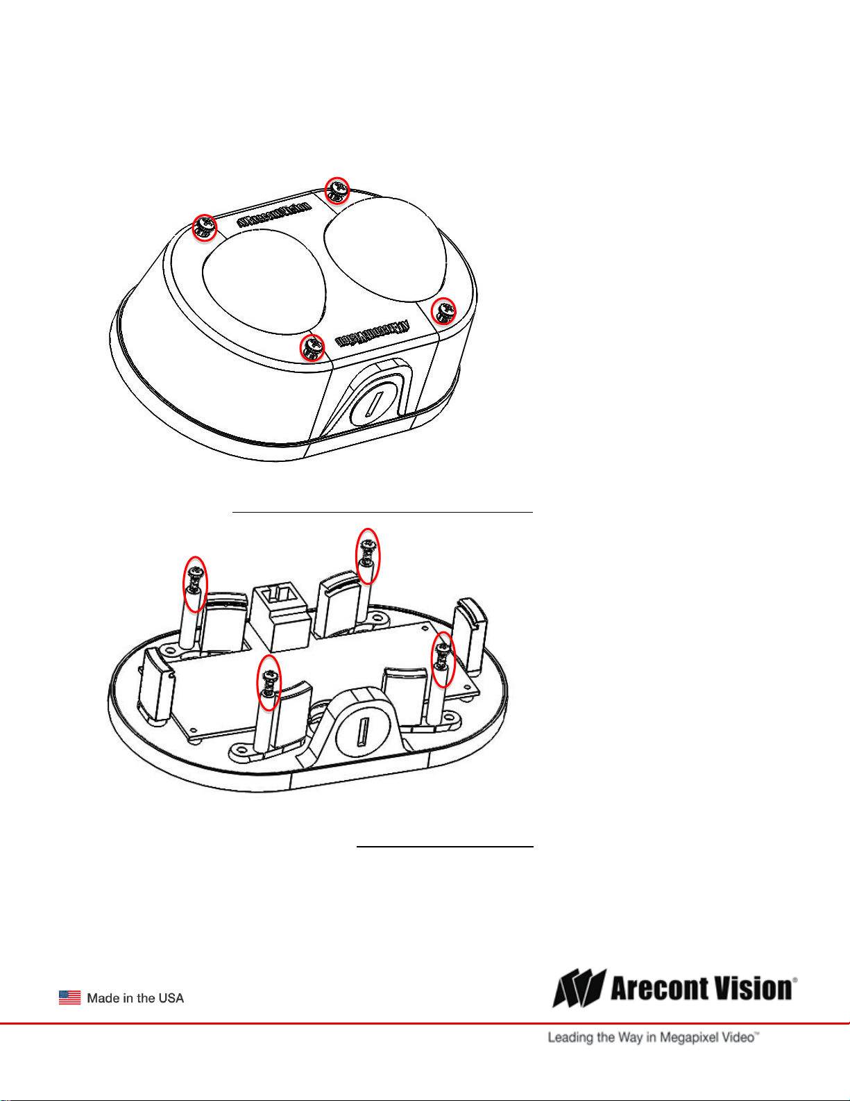
1. Determine a secure location to mount the camera.
2. Use the supplied security L-key, to loosen the four (4) screws which secure the cover.
PIC. 1
3. Remove the cover. Do not remove screws from the dome cover.
4. Use Phillips screwdriver to loosen the four (4) screws securing the camera to adapter plate.
PIC. 2 (some parts removed for clarity)
5. Separate Camera from Adapter Plate Do not remove the screws.
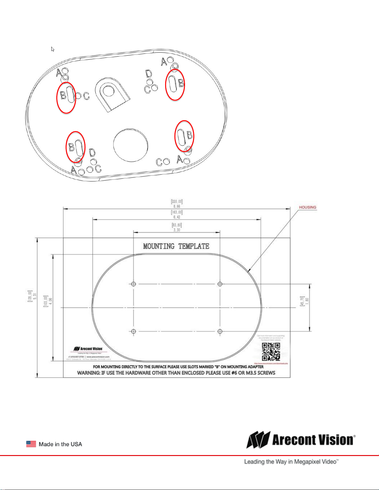
6. Use Surface Mount template and cable location to create mounting provisions for the camera.
7. Mount Adapter Plate by installing mounting hardware in 4 slots “B” in adapter plate
Page | 6 support@arecontvision.com
Page 7
Microdome Duo® Installation Manual
PIC. 3
8. Re-attach camera to adapter plate (Reverse step 4 and 5)
9. Re-attach cover to camera (Reverse step 2 and 3)
Page | 7 support@arecontvision.com
PIC 4
Page 8
Microdome Duo® Installation Manual
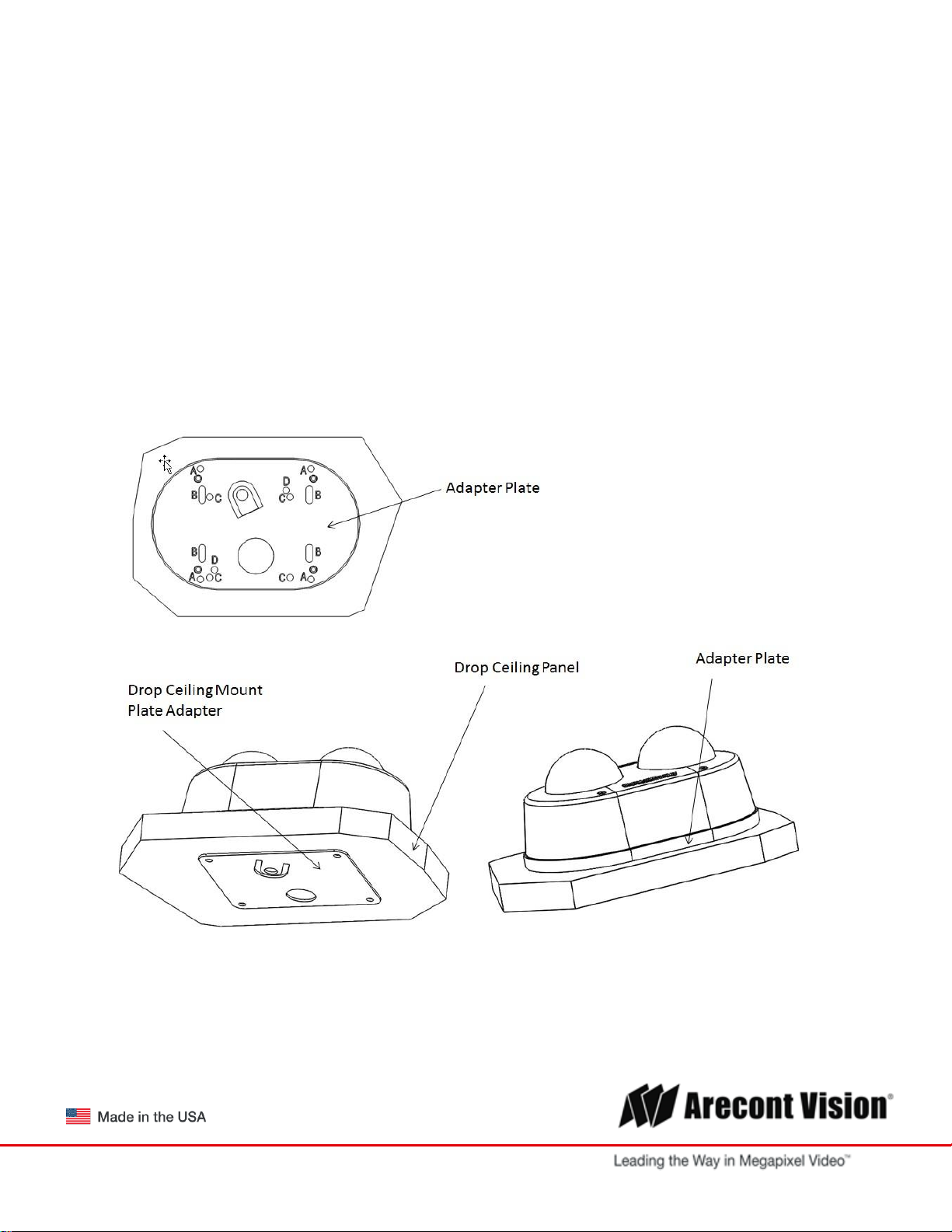
Drop Ceiling Mount Adapter Plate Installation
Repeat step 1-5 of Surface Installation (See Pic. 1-3)
6. Use template and cable location to create mounting provisions for the Plate. Use 3/16” drill bits for four
mounting holes in Drop Ceiling Panel.
7. Using enclosed #6-32 screws attach enclosed Drop Ceiling Mount Plate Adapter and Adapter Plate
onto opposite sides of Drop Ceiling Panel, so the panel is “sandwiched” between Adapter Plate and
Drop Ceiling Mount Plate Adapter. Use 4 slots “B” in Adapter Plate.
8. Re-attach camera to adapter plate (Reverse step 4 and 5)
9. Re-attach cover to camera (Reverse step 2 and 3)
10. Re-install the Drop Ceiling Panel and plug Customer Ethernet cable into female end of Camera
Ethernet cable.
Page | 8 support@arecontvision.com
PIC. 5
Page 9
Microdome Duo® Installation Manual
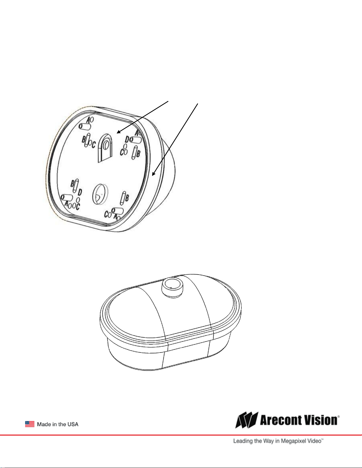
MDD-CAP Installation
Repeat step 1-5 of Surface Installation (See Pic. 1-3)
6. Insert Adapter Plate into the Cap and attach it to the cap, using the 4 screws through 4 “A” holes using
enclosed #6-32 screws.
Adapter Plate Cap
PIC 6.
7. Re-attach camera to adapter plate (Reverse step 4 and 5)
8. Re-attach cover to camera (Reverse step 2 and 3)
PIC. 7
Page | 9 support@arecontvision.com
Page 10
Microdome Duo® Installation Manual
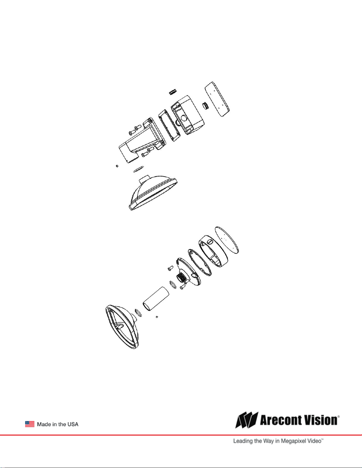
MDD-CMT/WMT Pendant Mount and Wall Mount Installation
Assembly (Pic. 7) can be used with wall mount or ceiling mount
Use MCD-CMT and MCD-WMT installation instructions for reference.
PIC 8
PIC. 9
Page | 10 support@arecontvision.com
Page 11

Microdome Duo® Installation Manual
MDD-FMA Flush Mount Installation
Note: MDD-FMA is designed for indoor use only. Grommet use is recommended.
1. Use template to cut the ceiling plate and create mounting provisions for the Flush Mount Ceiling Panel.
PIC. 10
2. Use the supplied security L-key, to loosen the four (4) screws which secure the cover on camera. (See
Pic. 1). Remove the cover.
3. Install Flush Mount Cover and tighten the four (4) screws which secure the Flush Mount Cover to
camera.
Page | 11 support@arecontvision.com
PIC. 11
Page 12

Microdome Duo® Installation Manual
4. Plug PoE cable (not shown for clarity)
5. Hold all four latches as shown on PIC. 12
PIC. 12
6. Insert camera into cutout prepared in step 1
PIC. 13
Page | 12 support@arecontvision.com
Page 13

Microdome Duo® Installation Manual
PIC. 14
7. Undo 4 screws shown and remove both Rings and Bubbles.
PIC. 15
Bubbles
Rings
8. Adjust Pan and Tilt for both modules as shown on page 14.
9. Re-attach Rings and Bubbles and tighten 4 screws from step 7.
Page | 13 support@arecontvision.com
Page 14

Microdome Duo® Installation Manual
Pan and Tilt Adjustment
1. Use the supplied security L-key, to loosen the four (4) screws which secure the cover. See Pic. 1.
2. Remove the cover.
3. Adjust the pan and tilt of each camera module to obtain the desired field of view.
Do not to press the remote focus motor against the sides of camera module when adjusting the field of
view (Pic. 5).
PIC. 16
4. Lock the camera head in place by tightening at least two of the three set-screws with the supplied flat-
head screwdriver. Do not over torque the screws (Pic. 8)
5. Re-attach cover to camera.
Page | 14 support@arecontvision.com
PIC. 17
Page 15

Microdome Duo® Installation Manual
Lens Replacement
1. Use the supplied security L-key, to loosen the four (4) screws which secure the cover. (See Pic. 1).
Remove the cover.
PIC. 18
2. Manually turn the lens counter clockwise, this may take several turns.
3. Screw the replacement lens clockwise until you feel some resistance and hit a hard stop.
4. Repeat for another camera module if necessary
Page | 15 support@arecontvision.com
Page 16

Microdome Duo® Installation Manual
Usage of Ethernet cable other than included M/F PoE cable.
1. Insert CAT 5E cable into Grommet Installation Tool as shown on Pic. 19.
2. If intend to use AC/DC power to power up the camera, insert the wire (not supplied) into grommet. See
instructions on page 23 for cable preparation.
3. If intend to use I/O cable, insert the supplied cable into grommet.
4. Insert Ethernet Cable with Tool on it into the Grommet as shown. Make sure the Grommet is installed
from the correct side.
5. Remove Grommet Installation Tool
Page | 16 support@arecontvision.com
PIC. 19
Page 17

Microdome Duo® Installation Manual
Electrical Characteristics
MIN
MAX
PIN
I/O CABLE WIRE COLOR
Input Voltage (V)
(Measured between “+” and “–“ terminals)
ON
2.9
6.3 3 WHITE (OUT +)
OFF
0
1.3 4 BLACK (OUT -)
Output Current (mA)
(Measured between “+” and “–“ terminals)
Applied Voltage Range: 0-80V
ON - 50 1 ORANGE (OUT +)
OFF
-
0.1
2
YELLOW (OUT -)
GROUND
5
GREEN
Connecting Digital I/O
1. To use digital I/O use 5-wire pigtail cable (included) and plug it into I/O connector (Pic 13). The color
coding is shown in Table 1 below
PIC. 20
5-Pin I/O Connector PoE Connector AC/DC Connector
Table 1.
The output consists of an optically coupled solid state relay (SSR) and the input has an optocoupler. Both the
SSR and optocoupler have an isolation voltage of 1500 VRMS between the external terminals and internal
camera circuitry. The input is further protected with a serial 250Ω resistor and a debouncing circuit.
Page | 17 support@arecontvision.com
Page 18

Microdome Duo® Installation Manual
Arecont Vision AUX I/O
ALARM
IN-
S
D
G
ALARM
OUT+
ALARM
OUT-
+
120V
100mA
(max)
-
+
Normally
Open/Close
-
0-12VDC
50mA
(max)
+
-
ALARM
IN+
3.3VO
GND
ALARM-OUT
ALARM-IN
250Ω
AUX I/O use case example
Page | 18 support@arecontvision.com
Page 19

Microdome Duo® Installation Manual
IN+ IN- GNDOUT+ OUT-
0-120VDC
100mA
(max)
+
-
Output Control
Terminals
External Status
Camera Status
Max Voltage
Max Current
OUT+ & OUT-
OPEN
OFF
120V
-
CLOSED
ON
-
100mA
OUTPUT Relay Control and Function
The camera has an output for activating an external device. The camera supports both transient and
continuous relay operation. You can operate the relay during an active connection using the API command set.
Typical applications include turning on lights or activating doors and locks.
Relay wiring with power source to the camera
Camera output can be turned on|off with the following command:
http://camera_ip/set?auxout=(“on”|“off”)
The following table shows the output control and electrical characteristics:
Page | 19 support@arecontvision.com
Page 20

Microdome Duo® Installation Manual
IN+ IN- GNDOUT+ OUT-
IN+
IN-
Open /
Close
IN+ IN- IN+ IN-
IN+
IN-
IN+
IN-
Normally Open Normally Closed
Input Unsupervised Alarms
Terminals
External
Status
Camera
Status
IN+ & IN-
OPEN
ON
CLOSE
OFF
INPUT Alarm Control and Detection
The input optocoupler supports two ways to connect external unsupervised alarms to Arecont Vision camera.
Only one of the following two schemes should be used at any given time.
OPTION-1: UNSUPERVISED ALARM DETECTION
In this scheme the IN+ & IN- terminals can be used for external signaling devices, such as door contacts or
motion detectors. Both normally open and normally closed devices are supported as shown below
The diagram below illustrates the unsupervised alarm conditions:
The following table shows how camera detects unsupervised alarms:
Camera status can be read with the following command:
http://camera_ip/get?auxin
OPTION-2: INPUT VOLTAGE DETECTION
Page | 20 support@arecontvision.com
Page 21

Microdome Duo® Installation Manual
IN+ IN- GNDOUT+ OUT-
0-12VDC
50mA
(max)
+
-
Input Voltage Detection
Terminals
External
Status
Camera
Status
Voltage
Range
Current
Range
IN- &
GND
OFF
ON
0-1V
0-2mA
ON
OFF
2-12V
10-50mA
In this scheme the IN- & GND terminals can be tied to an external power source. The camera can detect a
range of voltage to trigger an internal alarm on|off condition.
The following table shows the input voltage range and electrical characteristics:
The status of the camera can be read with the following command:
http://camera_ip/get?auxin
Page | 21 support@arecontvision.com
Page 22

Microdome Duo® Installation Manual
LED
Status
Description
Yellow
Flashing
Link has been established.
Solid
Normal Operation.
Green
Flashing
Camera has been accessed. Normal operation.
Solid
N/A
None
None
No Connection.
Camera Power Up using PoE
This product should be installed by a qualified service technician in accordance with the National Electrical
Code (NEC 800 CEC Section 60) or applicable local code. Make sure that your installation of wires complies
with Electrical Code of the local government where the camera is installed and no bare wires are exposed.
1. Remove cover from the camera as described on page 6.
2. Plug one end of Ethernet cable into female end of pre-installed camera Ethernet cable.
3. Plug opposite end of Ethernet cable into PoE port on 100Mbps Poe switch, Cat 5e or Cat 6 cables are
recommended.
4. Observe the yellow and green lights on Main Board PoE connector for connection status
Page | 22 support@arecontvision.com
Page 23

Microdome Duo® Installation Manual
Use of Auxiliary Power
1. If the camera is powered by a separate outside AC or DC power source, run the wire (not supplied)
through the grommet and connect the power cable to the 4-position connector on the Main Board. (see
Page 17 and 18 for illustration and detailed instructions)
2. The Poke-Home connector requires 18 AWG to 24 AWG wire (solid or stranded).
3. Please refer to picture below for more information on cable preparation and use
NOTE: Wiring methods shall be in accordance with the National Electrical Code/NFPA 70/ANSI, and with all
local codes and authorities having jurisdiction. Wiring should be UL Listed and/or Recognized wire suitable for
the application.
Page | 23 support@arecontvision.com
Page 24

Microdome Duo® Installation Manual
Camera Discovery, Setup, and Configuration
For camera discovery and setup, the AV IP Utility is recommended. The software can be
found on the CD included with your camera or at:
http://www.arecontvision.com/softwares.php.
The AV IP Utility has the ability to provide multiple discovery options, including broadcast and
multicast, check the status of a camera, change camera settings, import and export camera
settings via a .csv file, and update firmware and/or hardware from virtually anywhere with a
network connection.
Whether used for large installations that require an update to multiple settings, or smaller
installations where only one camera needs changed, the AV IP Utility tool is efficient and
convenient for mass or single camera uploads.
The AV IP Utility tool is compatible with all Arecont Vision megapixel cameras. The user
manual for the software is included on the CD that comes with your camera or available on
our website.
Page | 24 support@arecontvision.com
Page 25

Microdome Duo® Installation Manual
Network Protocols
The Arecont Vision MicroDome Duo cameras support RTSP, RTP/TCP, RTP/UDP, HTTP,
DHCP, TFTP, QoS, IP version 4 (IPv4) and IP version 6 (IPv6).
RTSP Cameras communicate with video management systems over Real Time Streaming
Protocol. Do not change the RTSP port unless you are sure your VMS does not use the
default setting.
RTP/TCP The Real-time Protocol/Transmission Control Protocol is best suited for
applications that require high reliability, and transmission time is relatively less critical.
RTP/UDP The Real-time Protocol/User Datagram Protocol is used for live unicast video,
especially when it is important to always have an up-to-date video stream, even if some
images are dropped.
HTTP The Hypertext Transfer Protocol is an application protocol for data transmission.
The HTTP interface on a camera allows users to connect to it with a web browser and
a GUI interface.
DHCP The Dynamic Host Configuration Protocol allows network administrators to centrally
manage and automate the assignment of IP addresses. DHCP should only be enabled if
using dynamic IP address assignment.
TFTP The Trivial File Transfer Protocol is a protocol used for file management and transfer.
On a camera the TFTP is used to receive commands or to stream video. TFTP lacks security
features.
QoS Quality of Service can assign a higher priority for a given type of IP traffic. A QoS-aware
network prioritizes network traffic and provides greater network reliability by controlling the
amount of bandwidth an application may use.
ONVIF – The Open Network Video Interface is a protocol specific to IP cameras that provides a
common interface for all camera manufacturers. ONVIF is an industry wide standard for camera
configuration, discovery, user authentication, security, event notification, and video streaming.
IPv4 The MicroDome Duo supports the IPv4 internet-layer protocol for packet-switched
internetworking across multiple IP networks. IPv4 uses 32-bit addressing which allows for
devices and users on the internet for routing traffic.
Page | 25 support@arecontvision.com
Page 26

Microdome Duo® Installation Manual
General Remote Focus
1.
To control the remote focus via the web interface, double click the camera within the AV IP Utility
(Figure 1) or open your preferred web browser and type the camera’s IP address (Figure 2).
NOTE: For supporting H.264 streaming on a webpage, the recommended browsers are Internet Explorer and
Firefox.
Figure 1: Double click via AV IP Utility
Figure 2: Type the camera IP address
2.
Scroll to the Focus Tab section.
NOTE: Additional information regarding the Arecont Vision® web interface is found separately in the AV IP
Utility Web Browser Manual via the Arecont Vision website.
3. Click the “Select Channel” and choose channel 1 (Please see image below)
4. Click the Full-range Focus button. The camera begins to autofocus with the lens stopping at the best
overall point of focus. When the focus area turns to Green, the autofocus is complete.
Page | 26 support@arecontvision.com
Page 27

Microdome Duo® Installation Manual
5. Please complete the same action for Channel 2 by following steps 2 to 5.
Page | 27 support@arecontvision.com
Page 28

Microdome Duo® Installation Manual
Menu
Feature
Description
Manual
Focus: +20,
+5, +1, -20,
-5, -1
Numbers indicate the level of focusing in order to adjust the field-of-view.
To set-up a focus area (if necessary), draw a rectangle with the mouse
(by left-clicking and dragging the mouse to a desired zoom size). To
automatically adjust focus, choose “Full-range Focusing” or “Short-range
Focusing” depending on the image clarity.
Full-range
Focus
Best for scenes that are completely out of focus. The camera
automatically scans the full focus range of the scene to find the best
focus position.
Short-range
Focus
Best for scenes that are slightly of out of focus. The camera quickly finetunes for a precise focus position.
Stop
Stops any command in progress.
Focus Aid
The higher the focus aid value means the more the lens is required to focus.
If the focus window box illuminates GREEN, the lens has reached its optimal
focus level.
If the focus window box illuminates RED, the lens is having difficulty reaching an
optimal focus level.
If the focus window box illuminates YELLOW, the focusing of the lens remains
unchanged.
If the focus window box illuminates GREY, the focusing of the lens has been
completed.
Select
Channel
Allows user to change settings of each channel. All the parameter settings in
“Settings” Menu only apply to the selected channel.
AV IP Utility Focus Tab
Page | 28 support@arecontvision.com
Page 29

Microdome Duo® Installation Manual
Administration and Password Setting
Administration is the place to set a password. Arecont Vision cameras support two levels of password-
protected access control. Camera authentication is compatible with RFC-2068 HTTP 1.1 and is supported by
all standard browsers and video surveillance software.
A. There are two types of users with the following reserved names:
admin – full access to all camera settings and live video.
viewer –viewing access only to live video.
Setting and removing the passwords is the privilege of the admin user, while the viewer can only use the
existing password, but not change it. Factory defaults erase all current passwords for both the admin and the
viewer. A newly shipped camera has no password protection and allows full anonymous access from the
network. In case the admin password has not been set, the camera has full anonymous access from the
network, even if the viewer password has been set.
B. Access control setup consists of three steps:
1. Set admin password (using http commands or using the camera’s web page, see below).
2. Log-in using the admin password and set the viewer password.
3. Communicate the viewer password to the users.
NOTE: The Password accepts a 16 character ASCII but cannot contain white space or following illegal
symbols: # % & ` “ ‘ < >.
In order to delete viewer password, log-in as admin and change the viewer password to a reserved password
empty – this would restore the full anonymous access to the camera. The admin user can change the viewer
password at any time, even without knowing the current viewer password.
NOTE: If the admin password has been set and forgotten, it can only be erased by AV IP Utility using key file.
Please contact Arecont Vision technical support to obtain the key file required to perform this function.
Page | 29 support@arecontvision.com
Page 30

Microdome Duo® Installation Manual
Reset to Factory Default
Press and hold the Reset Button, release it after 10 seconds. See picture below for approximate switch
position on board. The camera has been reset to the factory default.
If the camera is not connected to DHCP server, the camera will use Link-local address.
The Reset to Factory Default can be done via camera Web interface or AV IP Utility.
NOTE: Additional information regarding the Arecont Vision® web interface can be found separately in the AV
IP Utility Web Browser Manual via the Arecont Wision website http://www.arecontvision.com
Approx. Switch Position (board top view)
Page | 30 support@arecontvision.com
Page 31

Microdome Duo® Installation Manual
Troubleshooting
Before troubleshooting, visit http://www.arecontvision.com/ to ensure your camera has the most current
firmware version.
Page | 31 support@arecontvision.com
Page 32

Microdome Duo® Installation Manual
Support
1. Arecont Vision FAQ Page Located at ArecontVision.com
2. Check the following before you call:
Restore camera to factory default with AV200 or the camera webpage.
Upgrade to the latest firmware by visiting ArecontVision.com.
Isolate the camera on a dedicated network and test with AV200.
Swap the “troubled” camera with a known good camera to see if the problem follows the camera or
stays at the location.
3. Contact Arecont Vision Technical Support one of three ways:
1. Online Portal: Support.ArecontVision.com
2. Phone: 1.818.937.0700 (option #1)
3. Email: support@arecontvision.com
Page | 32 support@arecontvision.com
 Loading...