

Arecont Vision D4SO-AV2115DNv1-3312, D4SO-AV2115v1-3312, D4SO-AV5115DNv1-3312, D4SO-AV5115v1-3312 Installation Manual
Page 1
Arecont Vision D4SO Outdoor Dome Series Installation Manual
0 | Page
Page 2
Arecont Vision D4SO Outdoor Dome Series Installation Manual
G F E
C A D
D4SO Outdoor Dome Installation Manua l
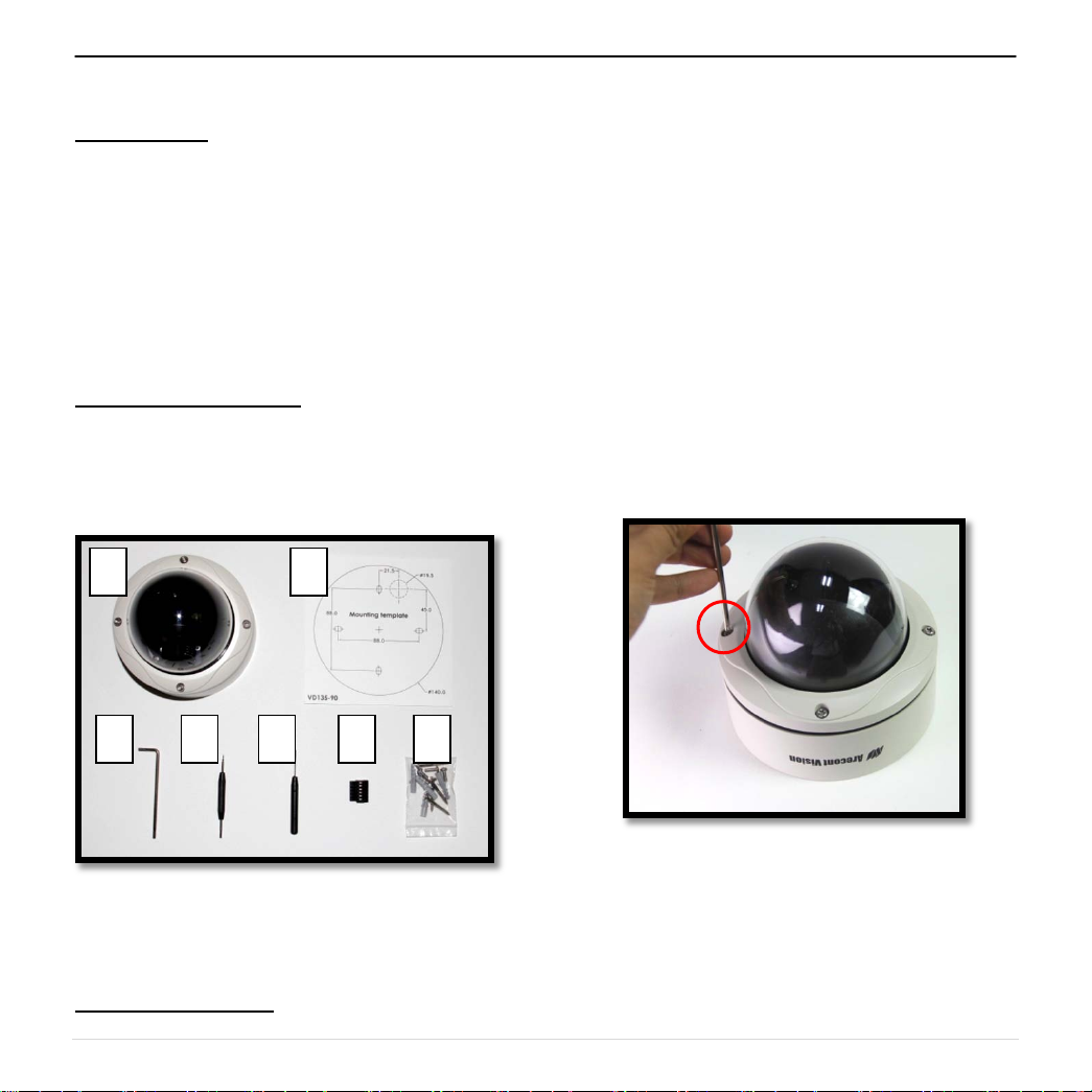
Inside the box:
A. Arecont Vision D4SO Dome Camera
B. Mounting template
C. Security L-key
D. One double sided hex key
E. One single sided hex key
F. 6-position external power & IO plug
G. Pack of four (4) wood screws and four (4)
dry wall anchors
Not included but needed:
• #1 Phillips head screw driver
• #2 Phillips head screw driver
• Small Flat Head screw driver
B
1. Remove camera and hardware from the
box.
2. Using the Mounting Template, prepare
the mounting provisions for camera
installation. NOTE: the 19.5mm diameter
hole on the Mounting template is where
the Ethernet cable will be exiting the
D4SO, align accordingly. If using the
side conduit hole, please see step 7
below.
3. Using Security L-key, loosen the four (4)
screws securing the dome cover (Image
2). Remove vandal resistant dome
cover. NOTE: Do not remove screws
from the dome cover.
Image 1
Mounting the Camera:
Image 2
1 | Page
Page 3

Arecont Vision D4SO Outdoor Dome Series Installation Manual
4. Run Ethernet cable through the hole on the
bottom of D4SO and plug it into the RJ45 port
on Arecont Vision’s compact MegaVideo®
camera. (Image 3) . NOTE: If the camera will
be powered via PoE, please skip to step 5.
Image 3
5. If the camera is powered by an outside power
supply, run power wires through the hole and
connect power wires to appropriate contacts
of 6-postion connector using small flat screw
driver and connect 6-position plug to camera
as shown in Image 4-1.
Note: Please make sure the polarity of the
AC/DC input on the camera match the way
wires are installed in connec tor shown in
Image 4-2.
Image 4-1
Image 4-2
6. Align the holes in the camera with the
prepared holes on the mounting surface.
Attach the camera to the mounting surface
with the wood screws or any optional
hardware suitable for the mounting surface.
2 | Page
Page 4

Arecont Vision D4SO Outdoor Dome Series Installation Manual
Gimbal Base
U Bracket
7. If you are using the side conduit opening,
remove the conduit plug by first removing the
socket set screw using one of provided Allen
keys (Image 5).
Image 5
Adjusting the Tilt and Pan:
8. To adjust the tilt, use a #1 Phillips screwdriver
to loosen the screw on the side of the U
bracket 1/4 turn (Image 6). CAUTION: Do not
remove the screw!
9. Adjust lens tilt as required and tighten the
screw. CAUTION: To properly install camera,
the U bracket needs to be installed between
the dome BASE and camera Bubble shown
in Image 7
Image 7
10. To adjust the pan, hold and turn the U bracket
as shown in Image 8.
0°
90°
Screw
Image 6
Pan=360°
Image 8
3 | Page
Page 5

Arecont Vision D4SO Outdoor Dome Series Installation Manual
B
A
Adjusting the Focus:
11. To focus the lens, loosen the three set screws
as shown in Image 9 and adjust each as
needed. A adjusts the zoom, B adjusts the
iris, C adjusts the focus.
Note: Adjust zoom first then focus!
Note: For more information on proper
focusing technique, please watch the
“Focusing Arecont Vision Megapixel
Cameras” Best Practices Training Video at
www.youtube.com/ArecontVision.
12. Secure the dome cover to the camera.
13. Tighten the set screw on the dome cover.
14. Rotate bubble to align camera with slot in
camera shield.
15. Remove the protective film from the camera
dome. NOTE: be cautious not to scratch the
vandal dome cover.
C
Image 9
4 | Page
 Loading...