

Page 1

SurroundVideo® Omni G3
SurroundVideo® OmniG3
Installation Manual
Models:
12 Megapixel
AV12375RS
AV12376RS
Installation Manual
20 Megapixel
AV20375RS
Page 2

SurroundVideo® Omni G3
Installation Manual
Contents
Package Contents ............................................................................................................................................ 3
Camera Overview ............................................................................................................................................. 6
General Installation ........................................................................................................................................... 7
Surface Mounting .........................................................................................................................................11
Wall Mounting...............................................................................................................................................18
Pendant Mounting .......................................................................................................................................20
Pole Mounting ..............................................................................................................................................22
Corner Mounting .........................................................................................................................................24
Electrical Box Adapter ................................................................................................................................26
Auxiliary I/O Functions ....................................................................................................................................27
Camera Power Up ...........................................................................................................................................31
Camera Discovery, Setup, and Configuration ...............................................................................................34
Network Protocols............................................................................................................................................34
Camera Preset Configurations .......................................................................................................................35
Home Position/ 360 Degree Preset Configuration ....................................................................................39
180/270 Degree Preset Configuration .......................................................................................................40
Create Custom Preset Configuration .........................................................................................................41
General Remote Focus, Pan, Tilt, Zoom .......................................................................................................44
AV IP Utility Focus/ Pan/ Tilt/ Zoom Tab .......................................................................................................45
Mounting Templates ........................................................................................................................................47
Support .............................................................................................................................................................48
Page | 2 support@arecontvision.com
+1.818.937.0700 877.CAMERA.8 www.arecontvision.com avsales@arecontvision.com
Page 3
SurroundVideo® Omni G3
Installation Manual
CAUTION!
1. Do not attempt to service a damaged unit yourself. Refer all servicing to qualified service
personnel.
2. Wiring methods shall be in accordance with the National Electrical Code/NFPA 70/ANSI, and
with all local codes and authorities having jurisdiction. Wiring should be UL Listed and/or
Recognized wire suitable for the application.
3. Always use hardware e.g. screws, anchors, bolts, locking nuts etc. which are compatible with
mounting surface and of sufficient length and construction to insure a secure mount.
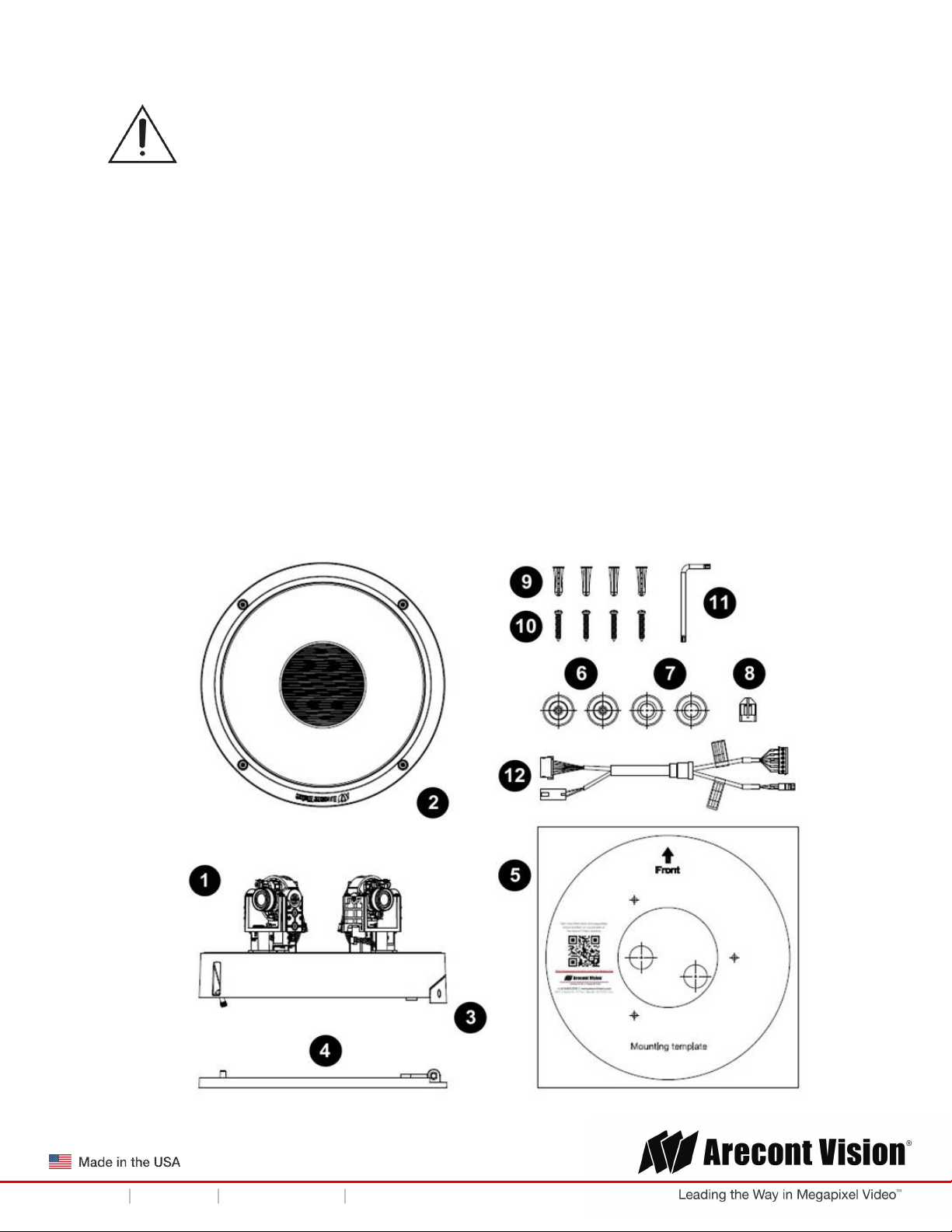
Package Contents
This equipment should be unpacked and handled with care. The original packaging is the safest
container in which to transport the unit and can be used if returning the unit for service. The packaging
contains:
Page | 3 support@arecontvision.com
+1.818.937.0700 877.CAMERA.8 www.arecontvision.com avsales@arecontvision.com
Page 4
SurroundVideo® Omni G3
Reference #
Description
Installation Manual
1 1x SurroundVideo® Omni G3
2
3
4
5
6
7
8
9
10
11
12
1x Dome Cover
1x Hinge Cover
1x Mounting Plate
1x Mounting template
2x Grommet with Through Hole
2x Grommet without Through Hole
1x Insertion Tool
4x PA4X25mm Drywall/ Masonry Mounting Anchors
4x PA4X25mm Wood/ Metal Sheet Screw
1x Security L-key
1x auxiliary power cable/ I/O Cable
1x CD with Manual and Software
Page | 4 support@arecontvision.com
+1.818.937.0700 877.CAMERA.8 www.arecontvision.com avsales@arecontvision.com
Page 5

SurroundVideo® Omni G3
Installation Manual
Warranty Information
Global (3 Year) Limited Warranty
ARECONT VISION warrants to Purchaser (and only Purchaser) (the “Limited Warranty”), that: (a) each
Product shall be free from material defects in material and workmanship for a period of thirty-six (36)
months from the date of shipment (the “Warranty Period”); (b) during the Warranty Period, the
Products will materially conform with the specification in the applicable documentation; (c) all licensed
programs accompanying the Product (the “Licensed Programs”) will materially conform with applicable
specifications. Notwithstanding the preceding provisions, ARECONT VISION shall have no obligation or
responsibility with respect to any Product that (i) has been modified or altered without ARECONT
VISION’s written authorization; (ii) has not been used in accordance with applicable documentation; (iii)
has been subjected to unusual stress, neglect, misuse, abuse, improper storage, testing or connection;
or unauthorized repair; or (iv) is no longer covered under the Warranty Period. ARECONT VISION
MAKE NO WARRANTIES OR CONDITIONS, EXPRESS, IMPLIED, STATUTORY OR OTHERWISE,
OTHER THAN THE EXPRESS LIMITED WARRANTIES MADE BY ARECONT VISION ABOVE, AND
ARECONT VISION HEREBY SPECIFICALLY DISCLAIMS ALL OTHER EXPRESS, STATUTORY AND
IMPLIED WARRANTIES AND CONDITIONS, INCLUDING THE IMPLIED WARRANTIES OF
MERCHANTABILITY, FITNESS FOR A PARTICULAR PURPOSE, NON-INFRINGEMENT AND THE
IMPLIED CONDITION OF SATISFACTORY QUALITY. ALL LICENSED PROGRAMS ARE LICENSED
ON AN “AS IS” BASIS WITHOUT WARRANTY. ARECONT VISION DOES NOT WARRANT THAT (I)
THE OPERATION OF THE PRODUCTS OR PARTS WILL BE UNINTERRUPTED OR ERROR FREE;
(II) THE PRODUCTS OR PARTS AND DOCUMENTATION WILL MEET THE END USERS’
REQUIREMENTS; (III) THE PRODUCTS OR PARTS WILL OPERATE IN COMBINATIONS AND
CONFIGURATIONS SELECTED BY THE END USER; OTHER THAN COMBINATIONS AND
CONFIGURATIONS WITH PARTS OR OTHER PRODUCTS AUTHORIZED BY ARECONT VISION
OR (IV) THAT ALL LICENSED PROGRAM ERRORS WILL BE CORRECTED.
The SurroundVideo Omni G3 motors are meant to be used for setup purposes or moving to preset
positions no more than one time per day. Excessive use will void the warranty. This camera is not
meant to be used as a traditional PTZ (pan tilt zoom) speed dome camera.
For RMA and Advance Replacement information visit http://www.arecontvision.com
Page | 5 support@arecontvision.com
+1.818.937.0700 877.CAMERA.8 www.arecontvision.com avsales@arecontvision.com
Page 6

SurroundVideo® Omni G3
Installation Manual
Camera Overview
The SurroundVideo® Omni G3, next generation multi-sensor, multi-megapixel camera was built to
withstand evolving customer change-requirements. The unique, future-proof, remote setup platform of
the SurroundVideo Omni G3 provides organizations of all sizes the flexibility to deploy a security
system that truly matches their video surveillance needs now; and again if requirements change in the
future. With its ground-breaking flexibility such as the ability to remotely move each of the four sensors
around the Omni track, the pan and tilt capabilities of the gimbals for an increased range of motion
when positioning the sensors, and the ability to remotely zoom and focus the lenses for a customized
field of view, the SurroundVideo Omni G3 provides customers with the confidence in a future-proof
investment. The SurroundVideo Omni G3 changes when you do.
The SurroundVideo Omni G3 multi-megapixel camera series features a choice of 12- or 20-megapixel
resolution options. These cameras provide an all-in-one solution for capturing wide area video
surveillance while maximizing the field-of-view and reducing the total number of cameras required
saving installers time and end users money.
Regardless of time-of-day, this camera is ideal for applications with challenging lighting conditions. The
series combines a day/night mechanical IR cut filter for the highest image quality at any time of day. For
applications with bright or over saturated lighting conditions, optional wide dynamic range delivers up to
100dB at full resolution and is available on select 12MP models. For applications with poor low lighting
conditions, Binning Mode increases the camera’s low light performance by combining pixels so that
more light can be collected.
SurroundVideo Omni G3 includes SNAPstream™ (Smart Noise Adaptation and Processing) technology
to reduce bandwidth without impacting image quality. Once mounted, the operator can quickly zoom,
focus and position the camera remotely, eliminating the need to adjust the camera on-site. No more
hassle individually installing multiple cameras to cover a wide area, manually focusing lenses, or risk
missing critical information.
SurroundVideo Omni G3 is designed for demanding environments. Subjected and certified to rigorous
dust and water tests, the IP66 rating, and its extended operating temperature range make it ideal for
outdoor applications. The IK-10 rated, rugged dome housing is perfect for deterring vandals since it can
withstand the equivalent of 55 kg (120 lbs) of force.
The camera offers advanced streaming capabilities and is designed on an efficient H.264 encoding
platform capable of delivering high quality video without straining the network. Power can be supplied
via a single Power-over-Ethernet compliant network cable or with power from a12-24V DC/24V AC
power supply.
The camera's interface allows for an intuitive, fast, and easy configuration; while the Free AV IP Utility
tool allows users to quickly configure multiple cameras at one time.
Page | 6 support@arecontvision.com
+1.818.937.0700 877.CAMERA.8 www.arecontvision.com avsales@arecontvision.com
Page 7
SurroundVideo® Omni G3
Installation Manual
General Installation
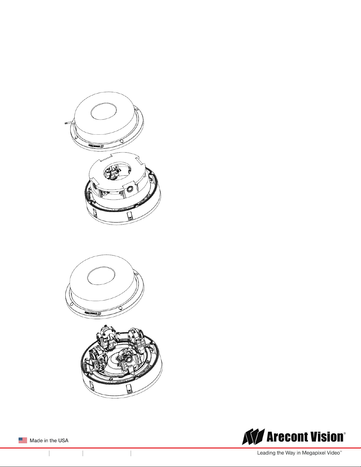
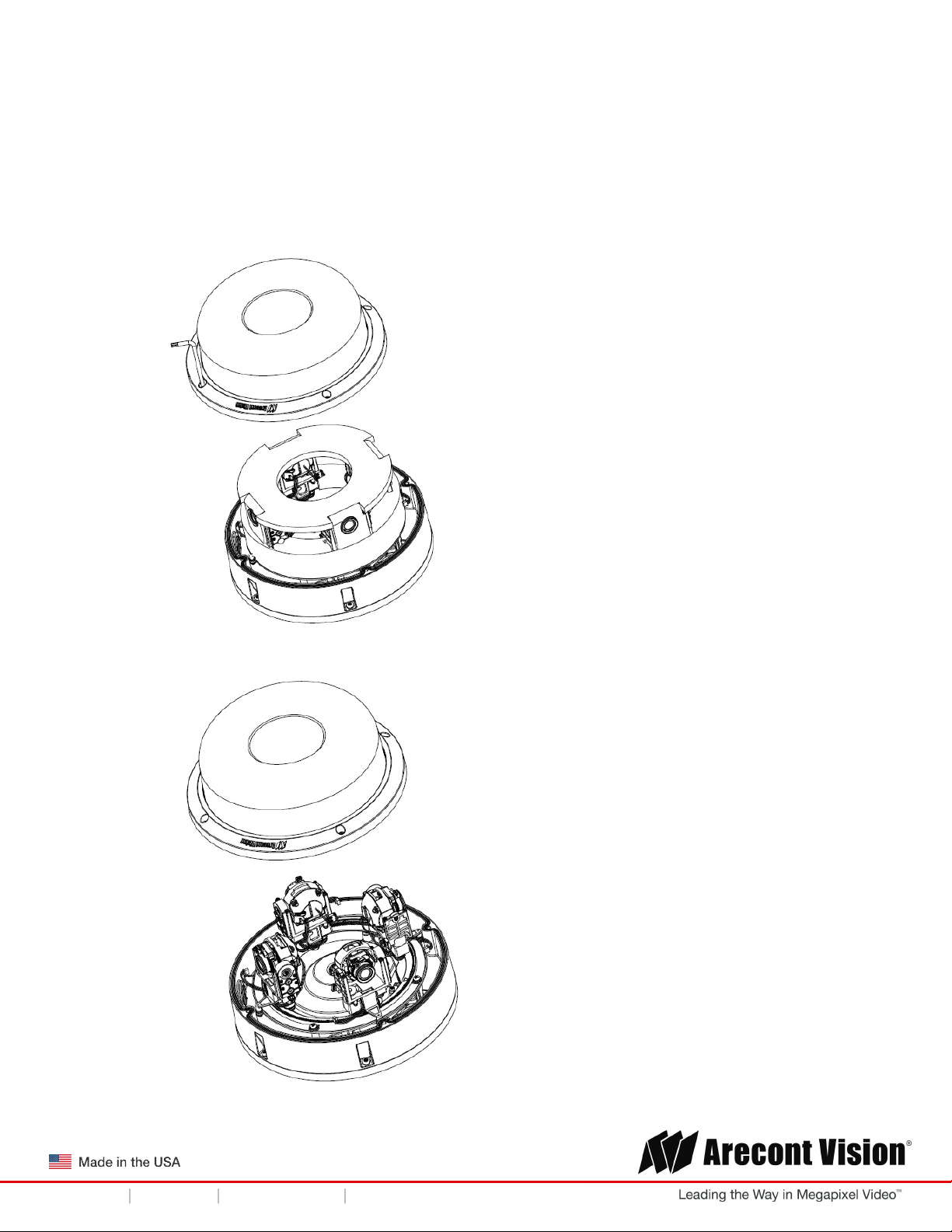
1. Determine a secure location to mount the camera.
2. Using the supplied security L-key loosens the four (4) screws securing the dome cover.
3. Remove the dome cover and protective foam. Do not remove screws from the dome cover.
Page | 7 support@arecontvision.com
+1.818.937.0700 877.CAMERA.8 www.arecontvision.com avsales@arecontvision.com
Page 8
SurroundVideo® Omni G3
Installation Manual
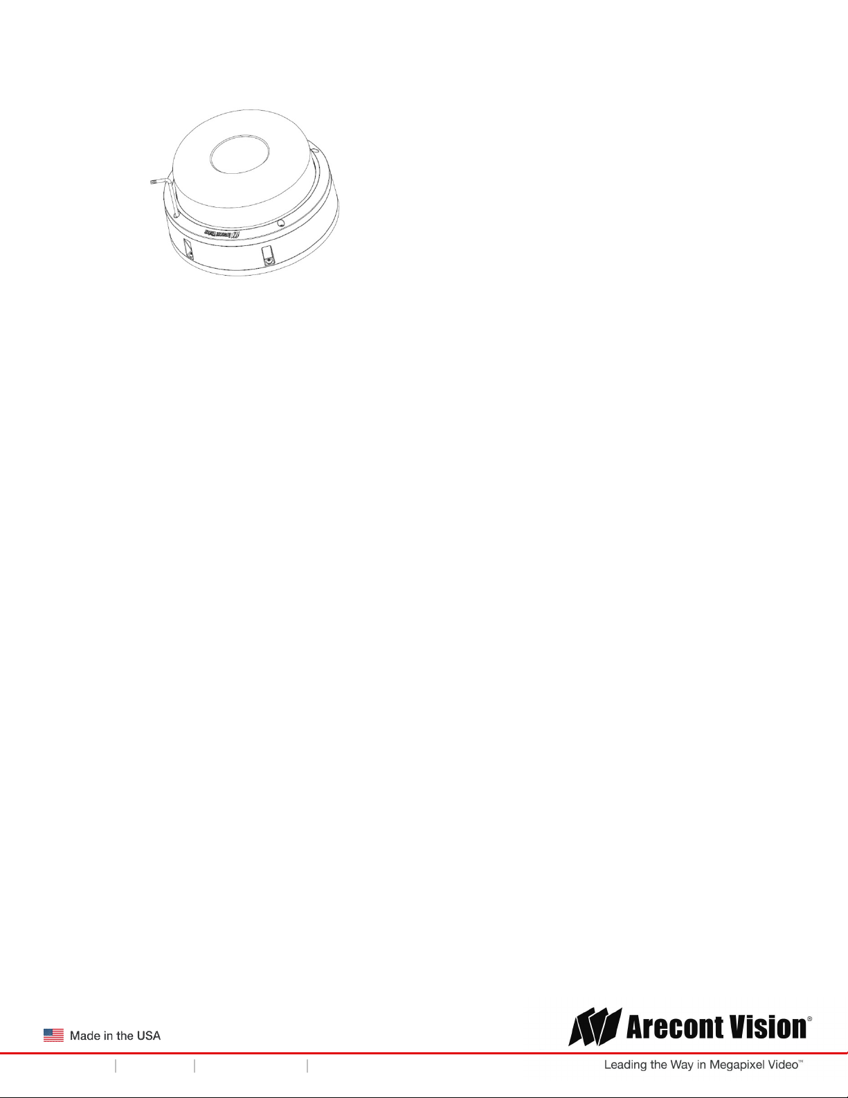
4. Re-attach the dome cover to the camera.
The SurroundVideo® Omni G3 camera has been designed to provide installers with flexible
mounting options for ceilings, walls, poles or corners.
NOTE: When mounting the camera outdoors or in a wet environment, use of the supplied
grommet is required. Ensure the grommet properly seats flush with the camera housing to
create a water-tight seal.
Page | 8 support@arecontvision.com
+1.818.937.0700 877.CAMERA.8 www.arecontvision.com avsales@arecontvision.com
Page 9
SurroundVideo® Omni G3
3
Installation Manual
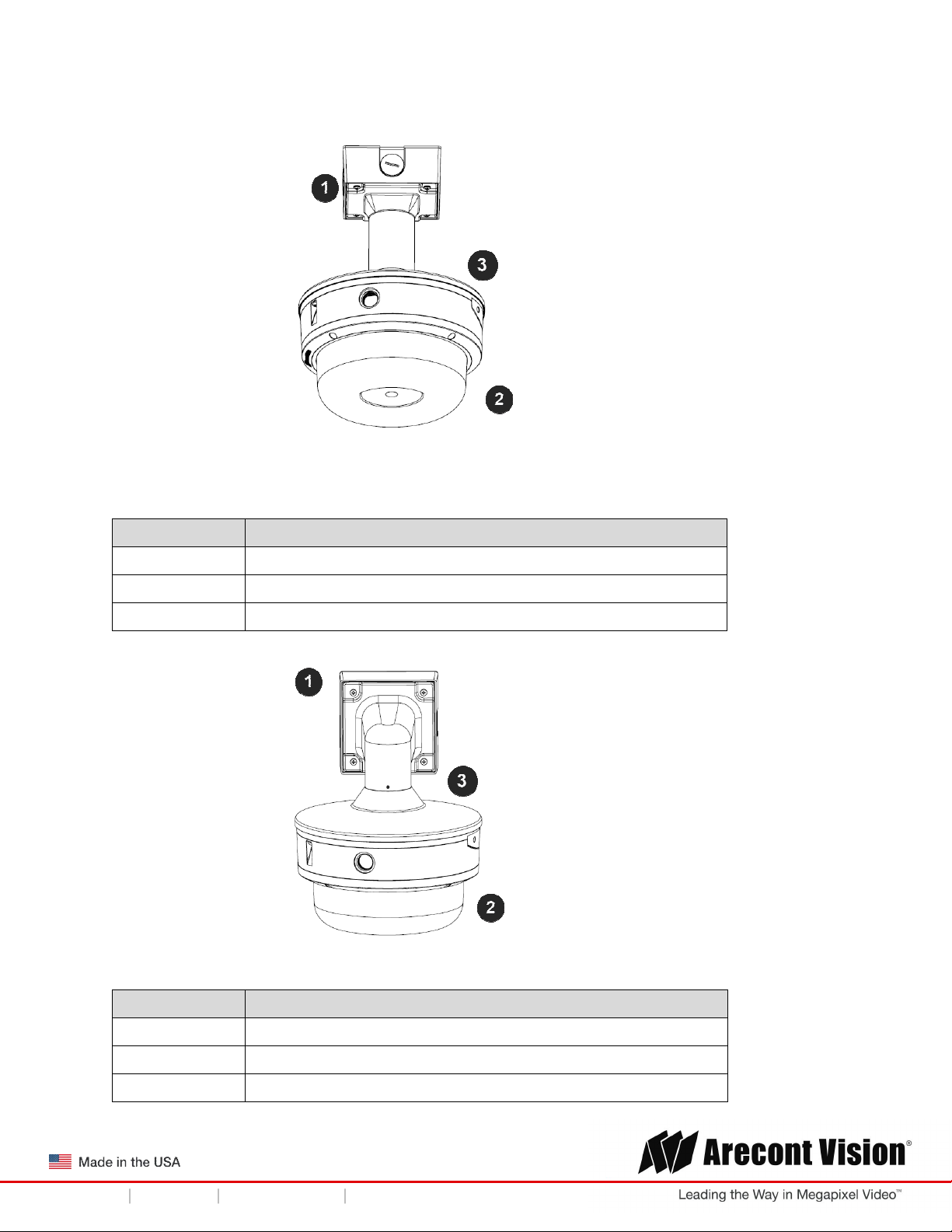
Ensure you have the proper compatible Arecont Vision mounting accessories prior to starting your
installation:
Pendant mount
Reference # Pendant Mount Components Required
1 Pendant mount (AV-PMJB) with integrated junction box
2
3
Wall mount
SurroundVideo® Omni G3 camera
SO3-CAP mounting cap
Reference # Wall Mount Components Required
1 Wall mount (AV-WMJB) with integrated junction box
2
Page | 9 support@arecontvision.com
+1.818.937.0700 877.CAMERA.8 www.arecontvision.com avsales@arecontvision.com
SurroundVideo® Omni G3 camera
SO3-CAP mounting cap
Page 10
SurroundVideo® Omni G3
Installation Manual
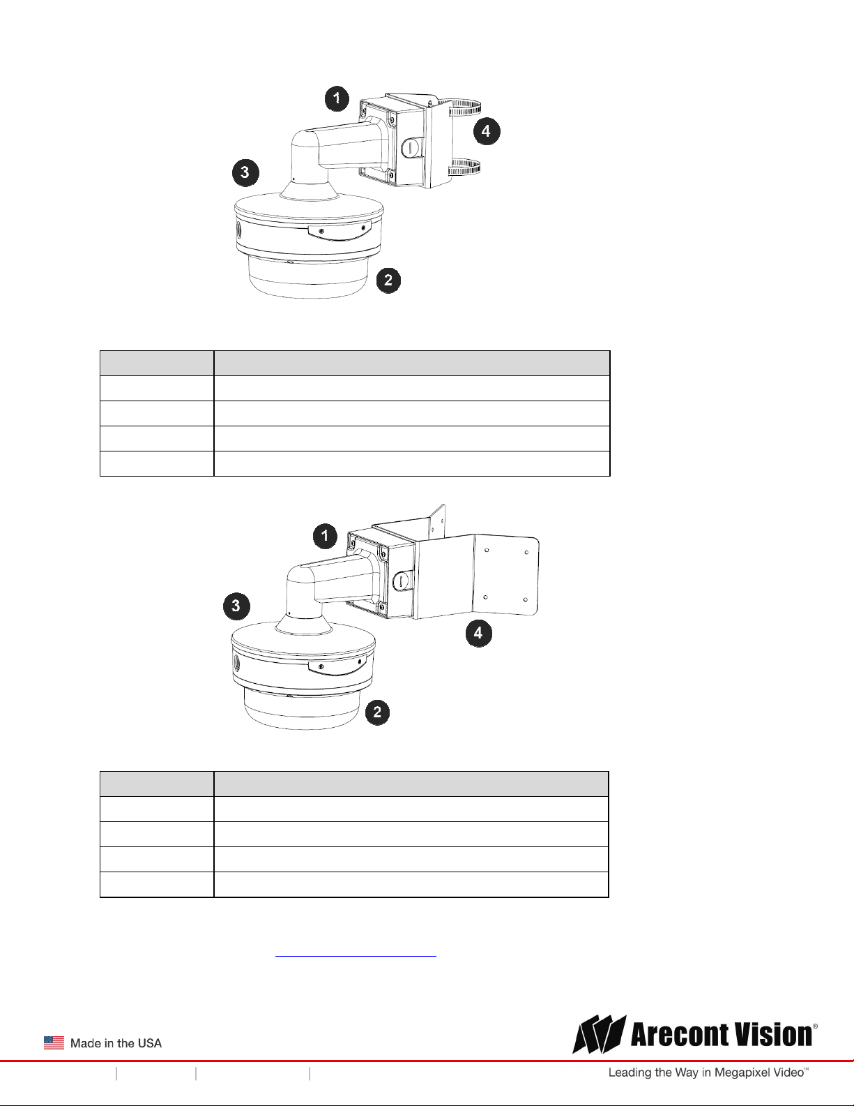
Pole mount
Reference # Pole Mount Components Required
1 Wall mount (AV-WMJB) with integrated junction box
2
3
4 AV-PMA pole mount adapter
Corner mount
Reference # Corner Mount Components Required
1 Wall mount (AV-WMJB) with integrated junction box
SurroundVideo® Omni G3 camera
SO3-CAP mounting cap
2
3
4 AV-CRMA corner mount adapter
4. Use the Arecont Vision software AV IP Utility located on the CD, QR code on the box, or available for
download at our website (www.arecontvision.com) for camera discovery and setup (see Instruction
Manual located on the CD or available on our website).
Page | 10 support@arecontvision.com
+1.818.937.0700 877.CAMERA.8 www.arecontvision.com avsales@arecontvision.com
SurroundVideo® Omni G3 camera
SO3-CAP mounting cap
Page 11
SurroundVideo® Omni G3
Installation Manual
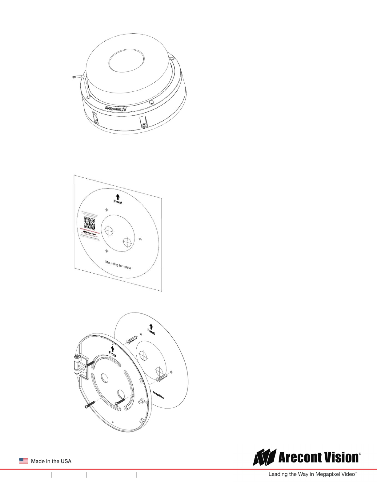
Surface Mounting
The SurroundVideo® Omni G3 camera can be directly attached onto hard ceilings.
1. Use the template, anchors, and screws provided.
2. Using the supplied security L-key loosens the four (4) screws securing the dome cover.
3. Remove the protective foam and discard.
4. Re-attach the dome cover to the camera.
Page | 11 support@arecontvision.com
+1.818.937.0700 877.CAMERA.8 www.arecontvision.com avsales@arecontvision.com
Page 12
SurroundVideo® Omni G3
Installation Manual
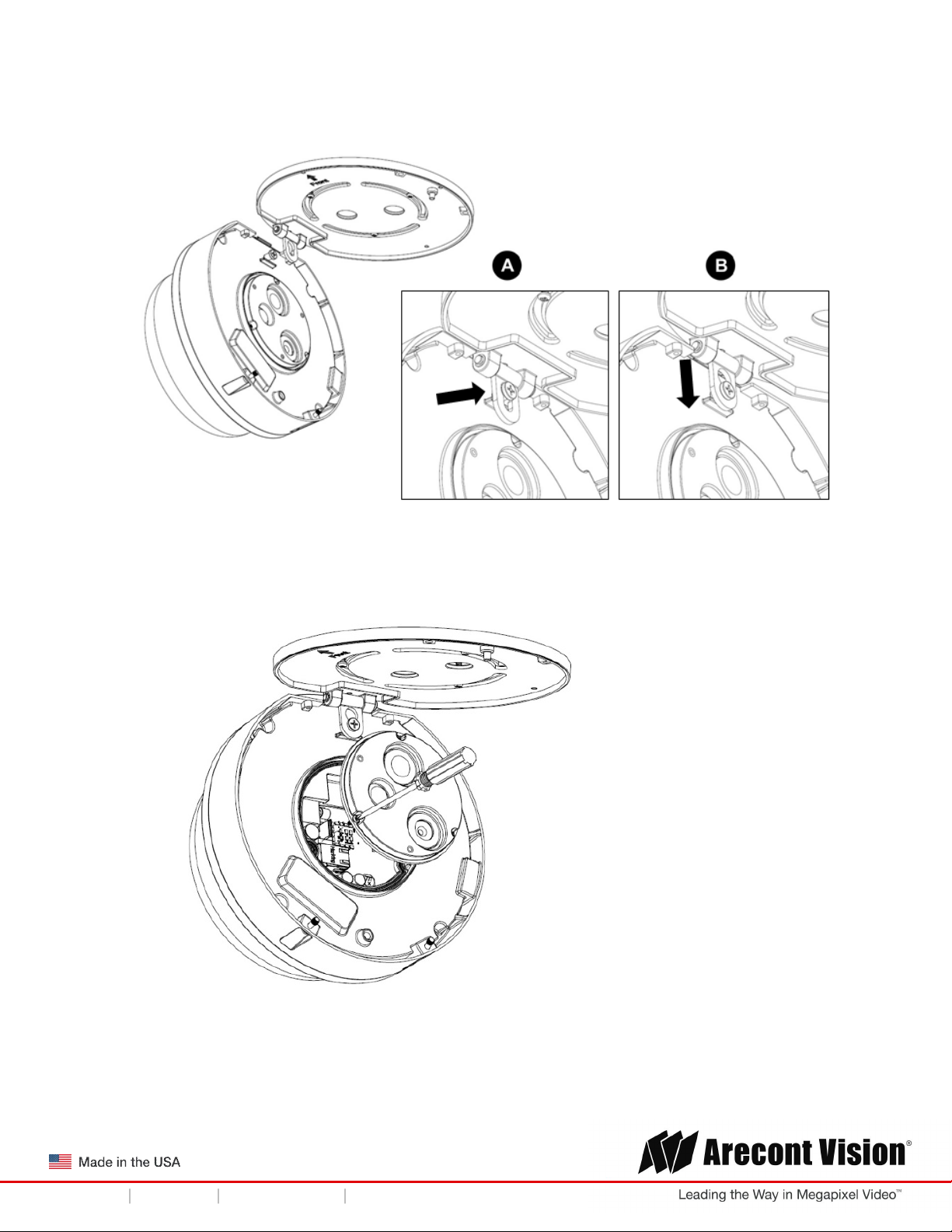
5. If presets will be used for 180°, 270°, or 360° configurations, orient the camera such that the
arrow, denoting the front of the camera, is pointing towards the center of the desired field of
view.
6. Attach the mounting plate to the ceiling using the supplied mounting hardware.
Page | 12 support@arecontvision.com
+1.818.937.0700 877.CAMERA.8 www.arecontvision.com avsales@arecontvision.com
Page 13
SurroundVideo® Omni G3
Installation Manual
7. Attach the camera to the mounting plate as shown in the image below. The camera will
“hang” from the hinge once properly attached.
8. Use a Phillips head screwdriver to loosen the three (3) screws on main housing cover to
access the network port.
Page | 13 support@arecontvision.com
+1.818.937.0700 877.CAMERA.8 www.arecontvision.com avsales@arecontvision.com
Page 14
SurroundVideo® Omni G3
Installation Manual
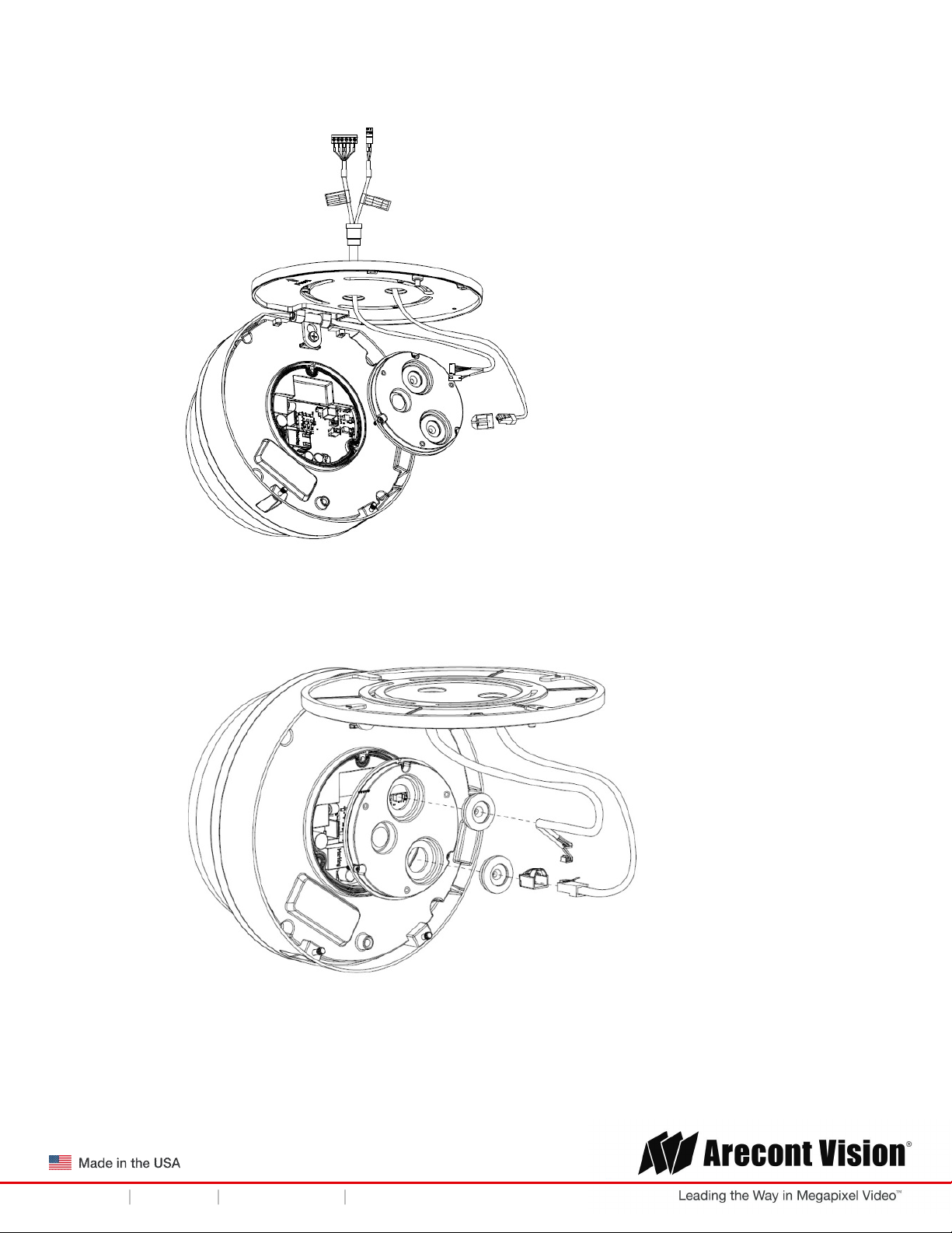
9. Run the Ethernet Cable (and the supplied power cable/ I/O cable,if necessary) through the
cable entry holes on the mounting plate.
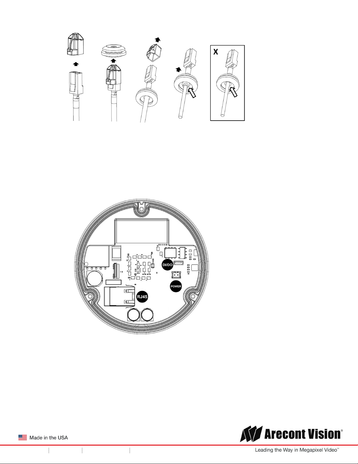
10. Prepare the network cable (and the supplied power cable/ I/O cable,if necessary) with the
supplied grommets by using insertion tool or terminate the RJ-45 connector to the cable after
passing through the grommet.
Page | 14 support@arecontvision.com
+1.818.937.0700 877.CAMERA.8 www.arecontvision.com avsales@arecontvision.com
Page 15
SurroundVideo® Omni G3
Installation Manual
NOTE: When mounting the camera outdoors or in a wet environment, use of the supplied
grommet is required. Ensure the grommet properly seats flush with the camera housing to
create a water-tight seal.
11. Connect the network cable (and the supplied power cable/ I/O cable, if necessary) to the
corresponding connectors inside the camera.
12. Align the holes on main housing cover with the holes on mounting plate, and install the main
housing cover back on to the camera.
Page | 15 support@arecontvision.com
+1.818.937.0700 877.CAMERA.8 www.arecontvision.com avsales@arecontvision.com
Page 16

SurroundVideo® Omni G3
Installation Manual
NOTE: If using the side connection of the NPT port, you need to install the supplied grommet
without a through hole on the main housing cover, and remove the cap covering the side
entrance, otherwise; leave the cap in place. If using the NPT port, always use Teflon tape
around the threads to ensure proper sealing. The conduit fits ¾” NPT standard.
13. Use the supplied security L-key to attach the camera to the mounting plate.
14. Swing the camera up into place and use a Phillips head screwdriver to the camera to the
mount plate. Use caution to not bend or pinch the cables during this step.
15. Secure the cover plate as shown in the image below.
Page | 16 support@arecontvision.com
+1.818.937.0700 877.CAMERA.8 www.arecontvision.com avsales@arecontvision.com
Page 17

SurroundVideo® Omni G3
Installation Manual
16. To configure the camera, reference the camera discovery, set-up and configuration section.
CAUTION! The captive screws must be used to properly secure the dome cover and
camera housing. Failure to use the captive fastener may result in serious injury. When
mounting the dome cover to the camera housing, ensure that the gasket is properly seated
and not folded. Failure to do so may result in water and dust ingress. Water damage from
improper installation is not covered by the warranty!
Page | 17 support@arecontvision.com
+1.818.937.0700 877.CAMERA.8 www.arecontvision.com avsales@arecontvision.com
Page 18

SurroundVideo® Omni G3
Installation Manual
Wall Mounting
For a proper wall mount installation, the AV-WMJB wall mount and SO3-CAP wall mount cap are
required (sold separately).
1. Using the Mounting template, prepare the mounting provisions for the camera installation.
2. Connect SO3-CAP cap and wall mount.
NOTE: The thread size for Top shield, pendant pole and mount is 1.5” NPT.
3. Attach the wall mount to the wall using the four drywall screws provided or any optional
hardware suitable for the mounting surface.
4. Run the Ethernet Cable and outside power cable (if necessary) through the supplied rubber
gasket and then through the wall mount. Ensure the gasket is seated properly.
5. Follow the Step#2 to Stpe#4 from Surface mount installation on P.11 and P.12.
6. If presets will be used for 180°, 270°, or 360° configurations, orient the camera such that the
arrow, denoting the front of the camera, is pointing towards the center of the desired field of
view.
7. Attach the mounting plate to the SO3-CAP with the supplied screws.
Page | 18 support@arecontvision.com
+1.818.937.0700 877.CAMERA.8 www.arecontvision.com avsales@arecontvision.com
Page 19

SurroundVideo® Omni G3
Installation Manual
8. Follow the Step#7 to Stpe#15 from Surface mount installation on P.13 to P.16.
9. To configure the camera, reference the camera discovery, set-up and configuration section.
CAUTION! The captive screws must be used to properly secure the dome cover and
camera housing. Failure to use the captive fastener may result in serious injury. When
mounting the dome cover to the camera housing, ensure that the gasket is properly seated
and not folded. Failure to do so may result in water and dust ingress. Water damage from
improper installation is not covered by the warranty!
Page | 19 support@arecontvision.com
+1.818.937.0700 877.CAMERA.8 www.arecontvision.com avsales@arecontvision.com
Page 20

SurroundVideo® Omni G3
Installation Manual
Pendant Mounting
For a proper pendant mount installation, the AV-PMJB pendant mount and SO3-CAP mounting cap
are required (sold separately).
1. Using the mounting template, prepare the mounting provisions for the camera installation.
2. Connect SO3-CAP, pendant pole and mount together.
NOTE: The thread size of top shield, pendant pole and mount is 1.5” NPT.
3. Attach the pendant mount to the ceiling using the four wood screws provided or any optional
hardware suitable for the mounting surface.
4. Run the Ethernet Cable and outside power cable (if necessary) through the supplied rubber
gasket and then through the pendant. Ensure the gasket is seated properly.
5. Follow the Step#2 to Stpe#4 from Surface mount installation on P.11 and P.12.
6. If presets will be used for 180°, 270°, or 360° configurations, orient the camera such that the
arrow, denoting the front of the camera, is pointing towards the center of the desired field of
view.
7. Attach the mounting plate to the SO3-CAP with the supplied screws.
Page | 20 support@arecontvision.com
+1.818.937.0700 877.CAMERA.8 www.arecontvision.com avsales@arecontvision.com
Page 21

SurroundVideo® Omni G3
Installation Manual
8. Follow the Step#7 to Stpe#15 from Surface mount installation on P.13 to P.16.
9. To configure the camera, reference the camera discovery, set-up and configuration section.
CAUTION! The captive screws must be used to properly secure the dome cover and
camera housing. Failure to use the captive fastener may result in serious injury. When
mounting the dome cover to the camera housing, ensure that the gasket is properly seated
and not folded. Failure to do so may result in water and dust ingress. Water damage from
improper installation is not covered by the warranty!
Page | 21 support@arecontvision.com
+1.818.937.0700 877.CAMERA.8 www.arecontvision.com avsales@arecontvision.com
Page 22

SurroundVideo® Omni G3
+1.818.937.0700 877.CAMERA.8
www.arecontvision.com
avsales@arecontvision.com
1 Remove conduit plug
Installation Manual
Pole Mounting
For a pole mount installation, the AV-WMJB wall mount, AV-PMA pole mount, and SO3-CAP mount
cap are required (sold separately).
1. Using the mounting template, prepare the mounting provisions for the camera installation.
2. Connect the wall mount cap and wall mount.
3. Attach the Junction Box Adapter to the Pole Mount Adapter as shown in Figure 1.
4. Remove the conduit plug on the junction box adapter and connect ¾” NPT conduit to the
junction box adapter (Figure 1).
Figure 1: Attach conduit to AV-JBA junction box adapter
Reference # Description
2
Connect ¾” NPT conduit to junction box adapter
(ensure use of water seal tape)
NOTE: Use silicon or water pipe seal tape to make sure no water leakage between conduit
pipe and junction box adapter.
5. Run the Ethernet cable and outside power cable (if necessary) through the supplied rubber
gasket and then through the Junction Box Adapter and AV-WMJB, Wall Mount Adapter. Ensure
the gasket is seated properly.
6. Attach the Wall Mount Adapter (AV-WMJB) to the Pole Mount Adapter (AV-PMA) as shown in
Figure 2.
Page | 22 support@arecontvision.com
+1.818.937.0700 877.CAMERA.8 www.arecontvision.com avsales@arecontvision.com
Page 23

SurroundVideo® Omni G3
Reference #
Description
1 Steel straps with compression screws
2 AV-WMJB wall mount
AV-PMA pole mount
Installation Manual
Figure 2: Attach wall mount adapter to pole mount adapter
3
4
7. Use the supplied two Steel Straps to attach the Pole Mount Adapter to the pole and tighten the
compression screws as shown in Figure 2.
8. To attach the camera to the Wall Mount Adapter (AV-WMJB), reference the Installation and Wall
Mounting section.
9. To configure the camera, reference the camera discovery, set-up and configuration section.
5
CAUTION! The captive screws must be used to properly secure the dome cover and
camera housing. Failure to use the captive fastener may result in serious injury. When
mounting the dome cover to the camera housing, ensure that the gasket is properly seated
and not folded. Failure to do so may result in water and dust ingress. Water damage from
improper installation is not covered by the warranty!
SO3-CAP mount cap
Apply Teflon water seal tape to the thread of ¾” NPT
pipe to avoid water leakage
Page | 23 support@arecontvision.com
+1.818.937.0700 877.CAMERA.8 www.arecontvision.com avsales@arecontvision.com
Page 24

SurroundVideo® Omni G3
Reference #
Description
1 Remove conduit plug
Installation Manual
Corner Mounting
For a corner mount installation, the AV-WMJB wall mount, AV-CRMA corner mount, and MDCAP mount cap are required (sold separately).
1. Using the Mounting template, prepare the mounting provisions for the camera installation.
2. Connect the wall mount cap and wall mount.
3. Attach the Junction Box Adapter to the Corner Mount Adapter as shown in Figure 1.
4. Remove the conduit plug on the junction box adapter and connect ¾” NPT conduit to the
junction box adapter as shown in Figure 1.
Figure 1: Attach conduit to SV-JBA junction box adapter
Connect ¾” NPT conduit to junction box adapter
NOTE: Use silicon or water pipe seal tape to make sure no water leakage between conduit pipe
and junction box adapter.
5. Run the Ethernet cable and outside power cable (if necessary) through the supplied rubber
gasket and then through the Junction Box Adapter and AV-WMJB, Wall Mount Adapter. Ensure
the gasket is seated properly.
6. Attach the Wall Mount Adapter (AV-WMJB) to the Corner Mount Adapter (AV-CRMA) as shown
in Figure 2.
2
(ensure use of water seal tape)
Page | 24 support@arecontvision.com
+1.818.937.0700 877.CAMERA.8 www.arecontvision.com avsales@arecontvision.com
Page 25

SurroundVideo® Omni G3
Reference #
Description
1 Attach corner mount adapter to exterior 90 corner wall
2 AV-WMJB wall
mount
3 SO3
-
CAP mount cap
5 AV-CRMA corner mount adapter
Installation Manual
Figure 2: Attach corner mount adapter to exterior corner wall
Apply Teflon water seal tape to the thread of ¾” NPT
6
7. Using the screws provided (or other hardware), attach the Corner Mount Adapter to an exterior
90 degree corner wall.
8. To attach the camera to the Wall Mount Adapter (AV-WMJB), reference the Installation and Wall
Mounting section.
9. To configure the camera, reference the camera discovery, set-up and configuration section.
CAUTION! The captive screws must be used to properly secure the dome cover and
camera housing. Failure to use the captive fastener may result in serious injury. When
mounting the dome cover to the camera housing, ensure that the gasket is properly seated
and not folded. Failure to do so may result in water and dust ingress. Water damage from
improper installation is not covered by the warranty!
Page | 25 support@arecontvision.com
+1.818.937.0700 877.CAMERA.8 www.arecontvision.com avsales@arecontvision.com
pipe to avoid water leakage
Page 26

SurroundVideo® Omni G3
Installation Manual
Electrical Box Adapter
The AV-EBAS and AV-EBAR electrical box adapter are used to attach the camera to a common
single, double or square electrical box.
1. Using the supplied machine screws from AV-EBAS or AV-EBAR, match the mounting holes on
the mounting plate with the threaded holes on the electrical box. Ensure every threaded hole is
matched with a mounting hole.
2. Attach the electrical box adapter to the user supplied electrical box.
Page | 26 support@arecontvision.com
+1.818.937.0700 877.CAMERA.8 www.arecontvision.com avsales@arecontvision.com
Page 27

SurroundVideo® Omni G3
Installation Manual
Auxiliary I/O Functions
The auxiliary input and output are accessible after removing dome cover as shown in Figure 1.
Figure 1
The output consists of an optically coupled solid state relay (SSR) and the input has an optocoupler.
Both the SSR and optocoupler have an isolation voltage of 1500 VRMS between the external terminals
and internal camera circuitry. The input is further protected with a serial 250Ω resistor and a
debouncing circuit.
Figure 2: AUX I/O use case example
Page | 27 support@arecontvision.com
+1.818.937.0700 877.CAMERA.8 www.arecontvision.com avsales@arecontvision.com
Page 28

SurroundVideo® Omni G3
External
Camera
Max
Max
Installation Manual
OUTPUT Relay Control and Function
The camera has an output for activating an external device. The camera supports both transient and
continuous relay operation. You can operate the relay during an active connection using the API
command set. Typical applications include turning on lights or activating doors and locks.
IN+ IN- GNDOUT+ OUT-
Figure 3: Relay wiring with power source to the camera
Camera output can be turned on|off with the following command:
http://camera_ip/set?auxout=(“on”|“off”)
The following table shows the output control and electrical characteristics:
Output Control
Terminals
OUT+ &
OUT- OPEN OFF 120V -
CLOSED ON - 100mA
Status
Status
Voltage
Current
Page | 28 support@arecontvision.com
+1.818.937.0700 877.CAMERA.8 www.arecontvision.com avsales@arecontvision.com
Page 29

SurroundVideo® Omni G3
External
Camera
Installation Manual
INPUT Alarm Control and Detection
The input optocoupler supports two ways to connect external unsupervised alarms to Arecont Vision
camera. Only one of the following two schemes should be used at any given time.
OPTION-1: UNSUPERVISED ALARM DETECTION
In this scheme the IN+ & IN- terminals can be used for external signaling devices, such as door
contacts or motion detectors. Both normally open and normally closed devices are supported as shown
in Figure 4:
Figure 4
Figure 5 illustrates the unsupervised alarm conditions:
Figure 5
The following table shows how camera detects unsupervised alarms:
Input Unsupervised Alarms
Terminals
IN+ & IN- OPEN ON
CLOSE OFF
Camera status can be read with the following command:
http://camera_ip/get?auxin
Status
Status
Page | 29 support@arecontvision.com
+1.818.937.0700 877.CAMERA.8 www.arecontvision.com avsales@arecontvision.com
Page 30

SurroundVideo® Omni G3
External
Camera
Voltage
Current
Installation Manual
OPTION-2: INPUT VOLTAGE DETECTION
In this scheme the IN- & GND terminals can be tied to an external power source. The camera can
detect a range of voltage to trigger an internal alarm on|off condition.
Figure 6
The following table shows the input voltage range and electrical characteristics:
Input Voltage Detection
Terminals
IN- &
GND OFF ON 0-1V 0-2mA
ON OFF 2-12V 10-50mA
The status of the camera can be read with the following command:
http://camera_ip/get?auxin
Status
Status
Range
Range
Page | 30 support@arecontvision.com
+1.818.937.0700 877.CAMERA.8 www.arecontvision.com avsales@arecontvision.com
Page 31

SurroundVideo® Omni G3
Reference #
Description
Installation Manual
Camera Power Up
This product should be installed by a qualified service technician in accordance with the
National Electrical Code (NEC 800 CEC Section 60) or applicable local code.
1. Connect the camera to a PoE port on 100Mbps network PoE switch using an Ethernet cable as
shown in the image below.
1 PoE Connector
2. If the camera is powered by an outside power supply, 12~24VDC or 24VAC, connect the power
cable.
3. Connect the PoE switch to your computer’s network port using an Ethernet cable.
Page | 31 support@arecontvision.com
+1.818.937.0700 877.CAMERA.8 www.arecontvision.com avsales@arecontvision.com
Page 32

SurroundVideo® Omni G3
Installation Manual
Auxiliary Power
If the camera is powered by a separate outside AC or DC power source, run the supplied power
cable through the access hole on the camera housing and connect the power cable to the 2position connector on the main camera board. The approximate location of the 2-position
connector is circled below.
NOTE: Cameras using auxiliary power with 802.1x enabled may need to manually power cycle the
camera to reconnect to the network.
CAUTION! Make the connections inside a watertight compartment. Isolate unused power
wires individually.
After connections are made, ensure that the watertight compartment is tightly closed and
cables and conduits are properly sealed to prevent ingress of water.
Page | 32 support@arecontvision.com
+1.818.937.0700 877.CAMERA.8 www.arecontvision.com avsales@arecontvision.com
Page 33

SurroundVideo® Omni G3
LED
Status
Description
Installation Manual
NOTE: A yellow LED on the rear of the camera illuminates after a few seconds.
The flashing yellow LED indicates that a link to your computer has been established.
A green LED will blink when the camera has been accessed.
Flashing Link has been established.
Yellow
Solid Normal Operation.
Flashing Camera has been accessed. Normal operation.
Green
Solid N/A
None None No Connection.
NOTE: Wiring methods shall be in accordance with the National Electrical Code/NFPA 70/ANSI, and
with all local codes and authorities having jurisdiction. Wiring should be UL Listed and/or Recognized
wire suitable for the application.
Page | 33 support@arecontvision.com
+1.818.937.0700 877.CAMERA.8 www.arecontvision.com avsales@arecontvision.com
Page 34

SurroundVideo® Omni G3
Installation Manual
System Requirements
Computer with Windows XP/Vista/7 operating system, network access, and Microsoft Internet Explorer
web browser version 9.0 or later (32-bit).
Camera Discovery, Setup, and Configuration
For camera discovery and setup, the AV IP Utility is recommended. The software can be found on the
CD included with your camera or at: http://www.arecontvision.com/softwares.php.
The AV IP Utility has the ability to provide multiple discovery options, including broadcast and multicast,
check the status of a camera, change camera settings, import and export camera settings via a .csv
file, and update firmware and/or hardware from virtually anywhere with a network connection.
Whether used for large installations that require an update to multiple settings, or smaller installations
where only one camera needs changed, the AV IP Utility tool is efficient and convenient for mass or
single camera uploads.
The AV IP Utility tool is compatible with all Arecont Vision® megapixel cameras. The user manual for
the software is included on the CD that came with your camera or available on our website.
Network Protocols
The Arecont Vision SurroundVideo® Omni G3 cameras support RTSP, RTP/TCP, RTP/UDP, HTTP,
DHCP, TFTP, QoS, IP version 4 (IPv4), and 802.1x.
RTSP – Cameras communicate with video management systems over Real Time Streaming Protocol.
Do not change the RTSP port unless you are sure your VMS does not use the default setting.
RTP/TCP – The Real-time Protocol/Transmission Control Protocol is best suited for applications that
require high reliability, and transmission time is relatively less critical.
RTP/UDP – The Real-time Protocol/User Datagram Protocol is used for live unicast video, especially
when it is important to always have an up-to-date video stream, even if some images are dropped.
HTTP – The Hypertext Transfer Protocol is an application protocol for distributed, collaborative,
hypermedia information systems.
DHCP – The Dynamic Host Configuration Protocol allows network administrators to centrally manage
and automate the assignment of IP addresses. DHCP should only be enabled if using dynamic IP
address notification, or if the DHCP can update a DNS server.
TFTP – The Trivial File Transfer Protocol is a simple, lock-step, File Transfer Protocol which allows a
client to get from or put a file onto a remote host. TFTP lacks security and most of the advanced
features offered by more robust file transfer protocols such as File Transfer Protocol.
Page | 34 support@arecontvision.com
+1.818.937.0700 877.CAMERA.8 www.arecontvision.com avsales@arecontvision.com
Page 35

SurroundVideo® Omni G3
Installation Manual
QoS – Quality of Service guarantees a certain level of a specified resource to selected traffic on a
network. A QoS-aware network prioritizes network traffic and provides a greater network reliability by
controlling the amount of bandwidth an application may use.
IPv4 – The MicroDome G2 supports the IPv4 internet-layer protocol for packet-switched
internetworking across multiple IP networks. IPv4 uses 32-bit addressing which allows for devices and
users on the internet for routing traffic.
802.1x – The IEEE 802.1x standard provides a general method for authentication and authorization in
IEEE-802 networks. Authentication is carried out via the authenticator, which checks the transmitted
authentication information using an authentication server and approves or denies access to the offered
services (LAN, VLAN or WLAN) accordingly.
Camera Preset Configurations
The Arecont Vision SurroundVideo® Omni G3 cameras support three predifined camera preset
configurations: 180 degree, 270 degree, and 360 degree. Also, the cameras support two custom preset
configurations.
- Home position
Four camera modules will move to the positions as the image shown in below. All four modules
zoom out to widest angle, and tilt up to zero degree.
Page | 35 support@arecontvision.com
+1.818.937.0700 877.CAMERA.8 www.arecontvision.com avsales@arecontvision.com
Page 36

SurroundVideo® Omni G3
Installation Manual
- 180 degree preset configuration
Four camera modules will move to the positions as the image shown in below. CH1/2/3 zoom in
to 60 degree H-FOV, and tilt down to 37 degree. CH4 zooms out to widest angle, and tilt down
to 135 degree.
- 270 degree preset configuration
Four camera modules will move to the positions as the image shown in below. CH1/2/3 zoom in
to 90 degree H-FOV, and tilt down to 37 degree. CH4 zooms out to widest angle, and tilt down
to 135 degree.
Page | 36 support@arecontvision.com
+1.818.937.0700 877.CAMERA.8 www.arecontvision.com avsales@arecontvision.com
Page 37

SurroundVideo® Omni G3
Installation Manual
- 360 degree preset configuration
Four camera modules will move to the positions as the image shown in below. All four modules
zoom in to 90 degree H-FOV, and tilt down to 37 degree.
- Custom preset configuration
User could define custom pan/tilt/zoom positions as the image shown in below.
1.
To control the camera preset configurations via the web interface, double click the camera
within the AV IP Utility (Figure 1) or open your preferred web browser and type the camera’s IP
address (Fig 2).
NOTE: For H.264 streaming support on a webpage, the recommended browsers are Internet
Explorer and Firefox.
Page | 37 support@arecontvision.com
+1.818.937.0700 877.CAMERA.8 www.arecontvision.com avsales@arecontvision.com
Page 38

SurroundVideo® Omni G3
Installation Manual
Figure 1: Double click via AV IP Utility
Figure 2: Type the camera IP address
2.
Click Presets Tab
NOTE: SurroundVideo® Omni G3 cameras are not to be used as traditional high speed PTZ cameras.
The motorized movement of the camera gimbals is meant for setup and configuration only. Movement
of the modules more than one time per day will void the warranty.
NOTE: Module CH2 will not pass the FRONT position shown on the mounting plate. This is to avoid
cable routing problems.
NOTE: Modules will stop moving once they hit the neighbor module during pan movement in either
direction
NOTE: Live video is disabled during pan/tilt adjustment.
NOTE: Additional information regarding the Arecont Vision® web interface is found separately in the AV
IP Utility Web Browser Manual via the Arecont Vision website.
Page | 38 support@arecontvision.com
+1.818.937.0700 877.CAMERA.8 www.arecontvision.com avsales@arecontvision.com
Page 39

SurroundVideo® Omni G3
Installation Manual
Home Position/ 360 Degree Preset Configuration
1. In the “Preset buttons” section, click “Home” or “360”
2. To make an adjustment to all 4 camera modules (without having to select each camera module
individually) you can select “1-4” from the drop down menu.
3.
To individually adjust each camera module, select the “Focus/PTZ” tab.
Page | 39 support@arecontvision.com
+1.818.937.0700 877.CAMERA.8 www.arecontvision.com avsales@arecontvision.com
Page 40

SurroundVideo® Omni G3
Installation Manual
NOTE: SurroundVideo® Omni G3 cameras are not to be used as traditional high speed PTZ cameras.
The motorized movement of the camera gimbals is meant for setup and configuration only. Movement
of the modules more than one time per day will void the warranty.
NOTE: Module CH2 will not pass the FRONT position shown on the mounting plate. This is to avoid
cable routing problems.
NOTE: Modules will stop moving once they hit the neighbor module during pan movement in either
direction
NOTE: Live video is disabled during pan/tilt adjustment.
NOTE: Additional information regarding the Arecont Vision® web interface is found separately in the AV
IP Utility Web Browser Manual via the Arecont Vision website.
180/270 Degree Preset Configuration
1. In the “Preset buttons” section, click “180” or “270”
2. To make an adjustment to the entire panoramic configuration (without having to select each
camera module individually) you can select “1/2/3” from the drop down menu. Doing this will
allow you to modify.
Page | 40 support@arecontvision.com
+1.818.937.0700 877.CAMERA.8 www.arecontvision.com avsales@arecontvision.com
Page 41

SurroundVideo® Omni G3
Installation Manual
3. To individually adjust each camera module, select the “Focus/PTZ” tab.
NOTE: SurroundVideo® Omni G3 cameras are not to be used as traditional high speed PTZ cameras.
The motorized movement of the camera gimbals is meant for setup and configuration only. Movement
of the modules more than one time per day will void the warranty.
NOTE: Module CH2 will not pass the FRONT position shown on the mounting plate. This is to avoid
cable routing problems.
NOTE: Modules will stop moving once they hit the neighbor module during pan movement in either
direction
NOTE: Live video is disabled during pan/tilt adjustment.
NOTE: Additional information regarding the Arecont Vision® web interface is found separately in the AV
IP Utility Web Browser Manual via the Arecont Vision website.
Create Custom Preset Configuration
1. In “Preset buttons” section, click “Create Preset 1” or “Create Preset 2”
Page | 41 support@arecontvision.com
+1.818.937.0700 877.CAMERA.8 www.arecontvision.com avsales@arecontvision.com
Page 42

SurroundVideo® Omni G3
Installation Manual
2. To adjust Focus/Pan/Tilt/Zoom positions for individual module or all four modules together via
Channel Selects.
3. Once having desired position for each module, click “Save Preset 1” or “Save Preset 2”
4.
Click “User Preset 1” or “User Preset 2” to get the saved custom preset configuration
Page | 42 support@arecontvision.com
+1.818.937.0700 877.CAMERA.8 www.arecontvision.com avsales@arecontvision.com
Page 43

SurroundVideo® Omni G3
Installation Manual
NOTE: SurroundVideo® Omni G3 cameras are not to be used as traditional high speed PTZ cameras.
The motorized movement of the camera gimbals is meant for setup and configuration only. Movement
of the modules more than one time per day will void the warranty.
NOTE: Module CH2 will not pass the FRONT position shown on the mounting plate. This is to avoid
cable routing problems.
NOTE: Modules will stop moving once they hit the neighbor module during pan movement in either
direction
NOTE: Live video is disabled during pan/tilt adjustment.
NOTE: Additional information regarding the Arecont Vision® web interface is found separately in the AV
IP Utility Web Browser Manual via the Arecont Vision website.
Page | 43 support@arecontvision.com
+1.818.937.0700 877.CAMERA.8 www.arecontvision.com avsales@arecontvision.com
Page 44

SurroundVideo® Omni G3
Installation Manual
General Remote Focus, Pan, Tilt, Zoom
1. To control the remote focus, pan, tilt, or zoom via the web interface, double click the camera
within the AV IP Utility (Figure 1) or open your preferred web browser and type the camera’s IP
address (Fig 2).
NOTE: For supporting H.264 streaming on a webpage, the recommended browsers are Internet
Explorer and Firefox.
Figure 1: Double click via AV IP Utility
Figure 2: Type the camera IP address
2.
Click Focus/PTZ Tab
3. Select the channel you would like to adjust focus, pan, tilt, or zoom
5. Follow the instruction from the table below to adjust Focus/Pan/Tilt/Zoom positions for each
individual module
Page | 44 support@arecontvision.com
+1.818.937.0700 877.CAMERA.8 www.arecontvision.com avsales@arecontvision.com
Page 45

SurroundVideo® Omni G3
Installation Manual
AV IP Utility Focus/ Pan/ Tilt/ Zoom Tab
Menu Feature Description
Manual Focus:
+20, +5, +1, -20, -5, -1
Full-range Focus
Short-range Focus
Stop Stops any command in progress.
Manual Pan:
+20, +10, +5, +1, -20, -10, -5,
-1
Manual Tilt:
+20, +10, +5, +1, -20, -10, -5,
-1
Manual Zoom:
+20, +5, +1, -20, -5, -1
Numbers indicate the level of Focusing in order to adjust
the field-of-view.
Best for scenes that are completely out of focus. The
camera automatically scans the full focus range of the
scene to find the best focus position.
Best for scenes that are slightly of out of focus. The
camera quickly fine-tunes for a precise focus position.
Numbers indicate the level of Pan in order to adjust the
field-of-view.
Numbers indicate the level of Tilt in order to adjust the
field-of-view.
Numbers indicate the level of Zooming in order to adjust
the field-of-view.
NOTE: SurroundVideo® Omni G3 cameras are not to be used as traditional high speed PTZ cameras.
The motorized movement of the camera gimbals is meant for setup and configuration only. Movement
of the modules more than one time per day will void the warranty.
NOTE: Module CH2 will not pass the FRONT position shown on the mounting plate. This is to avoid
cable routing problems.
NOTE: Modules will stop moving once they hit the neighbor module during pan movement in either
direction
Page | 45 support@arecontvision.com
+1.818.937.0700 877.CAMERA.8 www.arecontvision.com avsales@arecontvision.com
Page 46

SurroundVideo® Omni G3
Installation Manual
NOTE: Live video is disabled during pan/tilt adjustment.
NOTE: Additional information regarding the Arecont Vision® web interface is found separately in the AV
IP Utility Web Browser Manual via the Arecont Vision website.
Page | 46 support@arecontvision.com
+1.818.937.0700 877.CAMERA.8 www.arecontvision.com avsales@arecontvision.com
Page 47

SurroundVideo® Omni G3
Mounting Templates
Installation Manual
Page | 47 support@arecontvision.com
+1.818.937.0700 877.CAMERA.8 www.arecontvision.com avsales@arecontvision.com
Page 48

SurroundVideo® Omni G3
Support
1. Arecont Vision FAQ Page Located at ArecontVision.com
2. Check the following before you call:
Restore camera to factory default with AV200 or the camera webpage.
Upgrade to the latest firmware by visiting ArecontVision.com.
Isolate the camera on a dedicated network and test with AV200.
Swap the “troubled” camera with a known good camera to see if the problem follows the
camera or stays at the location.
3. Contact Arecont Vision Technical Support one of three ways:
1. Online Portal: Support.ArecontVision.com
2. Phone: 1.818.937.0700 (option #1)
3. Email: support@arecontvision.com
4. Use the Arecont Vision software AV IP Utility located on the CD, QR code on the box, or
available for download at our website (www.arecontvision.com) for camera discovery and setup
(see Instruction Manual located on the CD or available on our website).
Installation Manual
Page | 48 support@arecontvision.com
+1.818.937.0700 877.CAMERA.8 www.arecontvision.com avsales@arecontvision.com
 Loading...