

Arecont Vision AV1125IRv1x, AV2125DNv1x, AV2125IRv1x, AV3125DNv1x, AV3125IRv1x User Manual
...Page 1
Arecont Vision MegaView
TM
v1 Installation Manual
0 | Page
Page 2
Arecont Vision MegaView
D
A
B
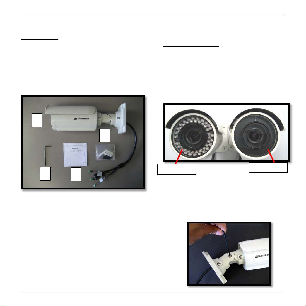
IR version
DN version
TM
v1 Installation Manual
MegaViewTM v1 Installation Manual
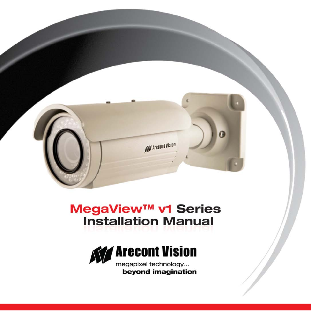
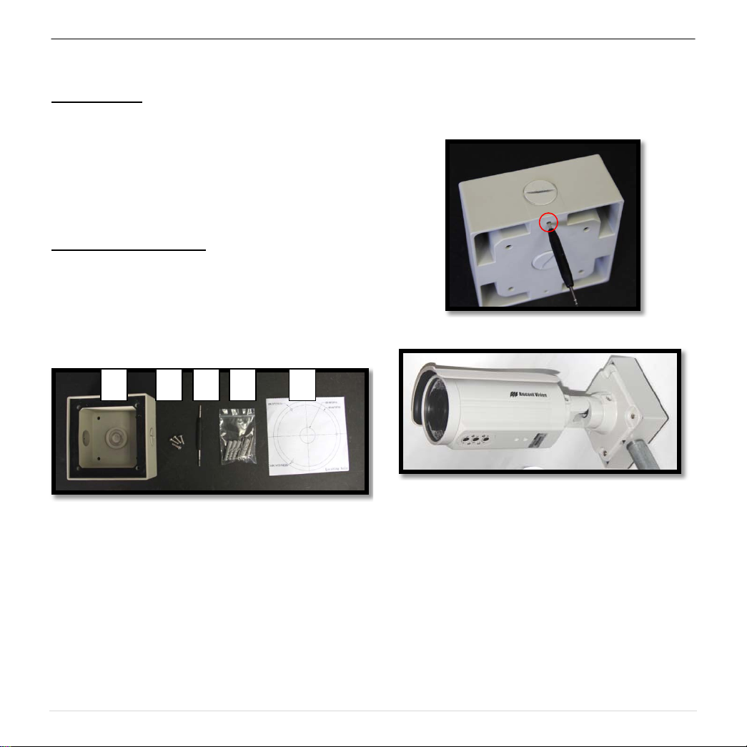
Inside the box:
A. Arecont Vision MegaView
B. Pack of four (4) wood screws and four (4)
dry wall anchors
C. Security L-key
D. Mounting Template
TM
v1
C
Image 1
Not included but needed:
Mounting the Camera:
1. Remove camera and hardware from the box.
NOTE : MegaView
versions, DN and IR, shown in image 2. Both
versions have motorized day night switcher
but only IR version supports an IR LED ring.
2. Use the Mounting Template to prepare the
mounting provisions for camera installation.
3. Use the security L-key to adjust
MegaView
position. ( Image 3)
TM
TM
v1 is available in two
Image 2
v1 bracket to appropriate
• #1 Phillips head screw driver
• #2 Phillips head screw driver
1 | Page
Page 3
Arecont Vision MegaView
Digital In
Auxiliary Power
PoE RJ45
°
360
°
°
TM
v1 Installation Manual
Image 3
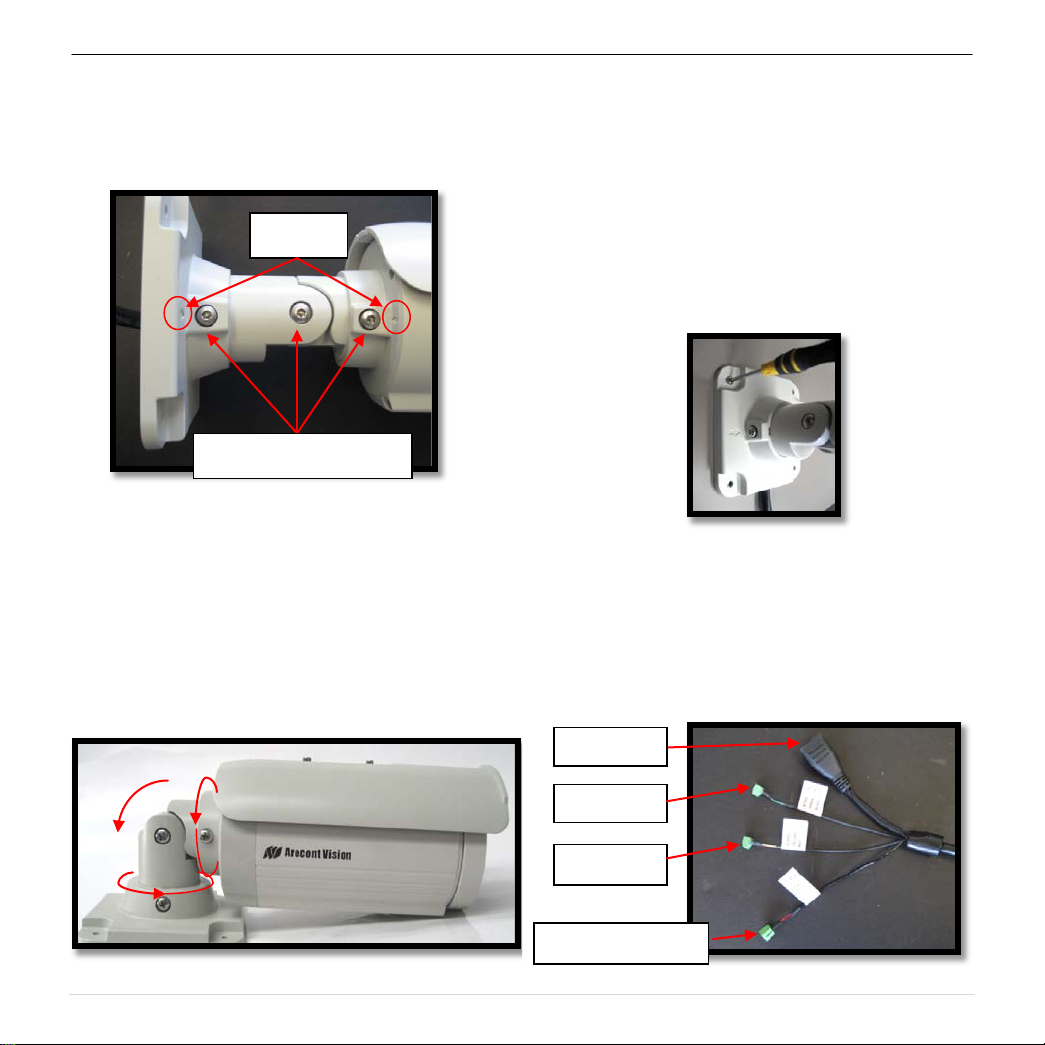
CAUTION: Only adjust the screws with an
arrow pointing to them on the bracket base
and camera body (Image 4)
Arrow
Adjustable Screws
Image 4
NOTE : Bracket screws are all security
screws that are tamper-resistant.
NOTE : Bracket with 3 axes enables easy
installation in any location, including 360°
camera body rotation, 90° tilt, 360° bracket
rotation. (image 5)
4. Align the holes in the camera with the
prepared holes on the mounting surface.
Attach the camera to the mounting surface
with the wood screws or any other hardware
that fits the mounting application. (im age 6)
NOTE: Use junction box adapter, SV-JBA, to
ensure a water tight installation as shown in
Page 5. Use of silicon does not guarantee a
water resistant install.
Image 6
5. Plug Ethernet cable into the MegaView
PoE Female RJ45 connector. (Image 7)
NOTE: MegaView
solution to power the camera, IR illuminator
and fan.
TM
v1 is a total PoE class 3
TM
v1
90
360
Image 5
Digital Out
Image 7
2 | Page
Page 4
Arecont Vision MegaView
Electrical
Output current (mA)
Yellow
Digital OUT +
Red
Digital OUT –
Green
Digital IN +
Black
Digital IN -
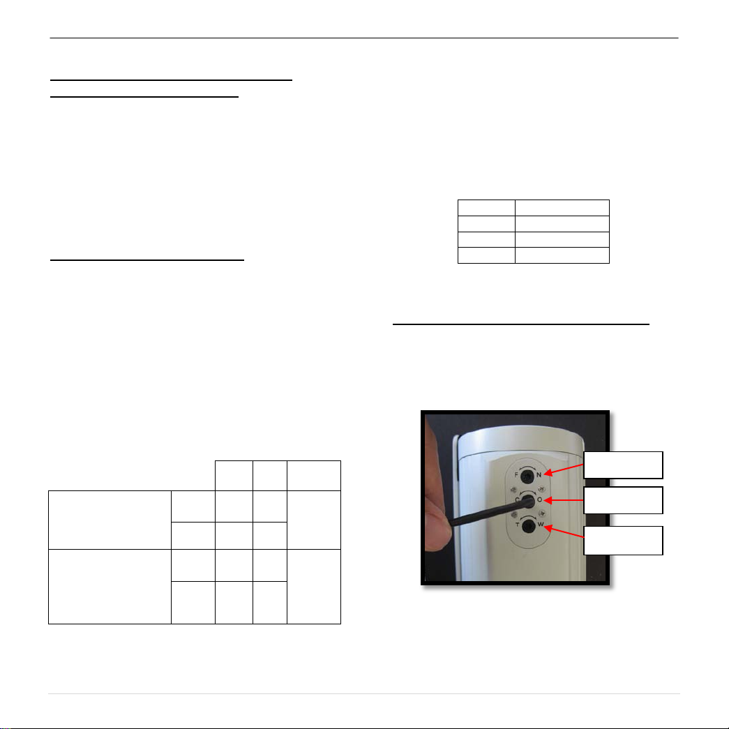
Iris
Zoom
Focus
TM
v1 Installation Manual
Optional: Connecting External Power for
Camera, IR Illuminator and Fan.
6. To use the external power, 12-48VDC or
24VAC, to power on camera, IR illuminator
and fan, connect external power with pigtail
cable connector (Image 7)
NOTE: MegaView
TM
v1 cameras contain fan
which is always on.
Optional: Connecting Digital I/O:
7. To use digital I/O, connect digital I/O with
pigtail cable connector. (Image 7)
NOTE: MegaView
TM
v1 DN version supports
both digital input and output; IR version only
supports digital input.
NOTE: Table 1 shows electrical
characteristics and Table 2 shows cable color
for digital in and out.
Characteristics:
Input voltage (V)
(measured between
+ and – terminals)
OFF 0 1.3
Min Max Camera
ON 2.9 6.3
IR & DN
Versions
NOTE: Both the input and the output are electrically
isolated from the rest of the camera’s electrical
circuitry via general-purpose photo couplers. The
input is additionally protected with a serial 250 Ohm
resistor, and a debouncing circuit. Dur atio n of
any input signal should be at least 5 ms to comply
with the requirements of the debouncing circuit.
Table 2
Adjusting the Focus, Iris and Field of View:
8. To adjust focus, iris and field of view, use
security L -key to adjust external lens screws
shown in Image 8.
(measured between
+ and – terminals)
Applied Voltage
Rage: 0 - 80V
ON - 50
OFF - 0.1
Table 1
DN
version
Only
Image 8
3 | Page
Page 5
Arecont Vision MegaView
TM
v1 Installation Manual
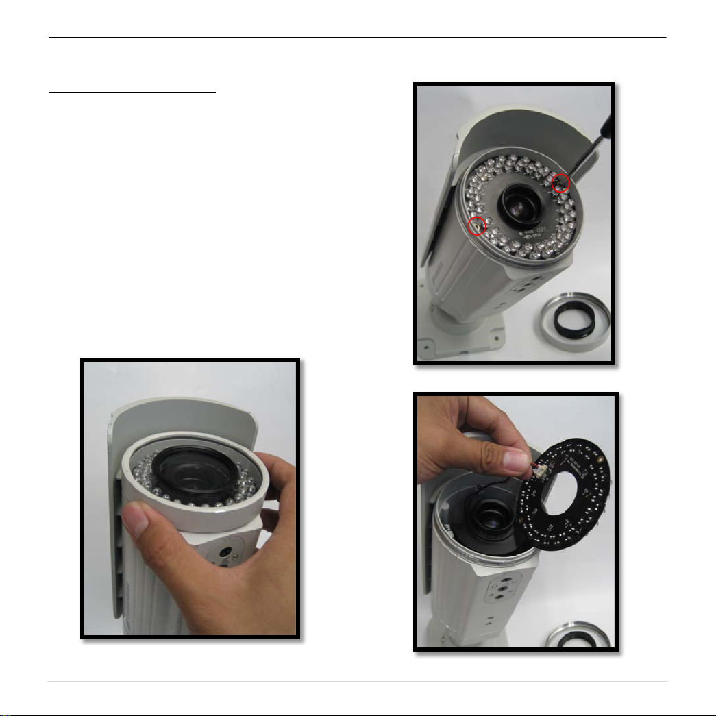
Replacing the IR LED board:
9. Unscrew glass ring (Image 9)
10. Use Phillips screwdriver to remove IR LED
board (Image 10)
11. To replace IR LED board, unplug cable and
replace new IR LED board (Image 11)
NOTE: Only MegaView
accommodate a replacement IR LED board.
IR LED Board cannot be added to DN
version.
NOTE: IR LED board part number: M00009416
TM
v1 IR version can
Image 10
Image 9
Image 11
4 | Page
Page 6

Arecont Vision MegaView
SV-JBA
Recommended!
TM
v1 Installation Manual
Important Note
Correct installation for outdoor application of MegaView™ v1
Correct Installation:
Please install the MegaView™ v1 with
junction box adapter (SV-JBA) to avoid risk of
water leakage in outdoor applications as
shown in Image 12.
MegaView
Im age 12
Note: Please see how to install SV-JBA on page 6.
Incorrect Installation:
Attaching the MegaView™ v1 directly onto a
wall surface may result in water leakage, see
Image 13.
Not Recommended!
Image 13
NOTE: Water damage from improper installation is
not covered by the warranty!
5 | Page
Page 7
Arecont Vision MegaView
B C A D E
TM
v1 Installation Manual
MegaView™v1 Junction Box Adapter (SV-JBA) Installation Instruction
Inside the box:
A. Junction Box Adapter
B. Pack of four (4) machine screws
C. One double sided hex key
D. Pack of four (4) wood screws and four (4)
dry wall anchors
E. Mounting Template
Not included but needed:
• #2 Phillips head screw driver
• ¾” NPT Conduit (if necessary)
NOTE: SV-JBA is same unit used for MegaDome
2 wall mount and SurroundVideo
®
wall mount
hardware suitable for the mounting
surface.
®
Image 15
Image 14
1. Remove Junction Box and hardware from
the box
2. Remove the conduit plug by first removing
the socket set screw using one of provided
hex keys shown in Image 15
3. Attach Junction Box Adapter to the wall
using drywall screws or any optional
4. Connect ¾” NPT Conduit to Junction Box
5. Run Ethernet Cable and outside power cable
6. Attach Megaview™ v1 to Junction Box
Image 16
Adapter shown in Image 16.
(if necessary) through the Junction Box
Adapter and connect to Megaview™ v1 pigtail
cable.
Adapter as shown in Image 16.
6 | Page
Page 8
Arecont Vision MegaView
MegaView™ v1
A
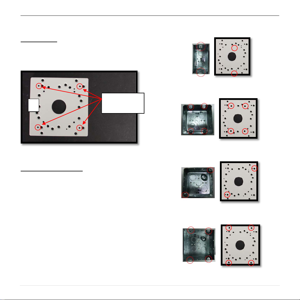
MegaView™v1 Electrical Box Adapter (SV-EBA) Installation Instructions
Inside the box:
A. Electrical Box Adapter
B. Pack of four (4) machine screws
TM
v1 Installation Manual
Bracket holes
Image 18-1 Single gang box
Not included but needed:
• #2 Phillips head screw driver
• Common Electrical Box, such as single
NOTE: SV-EBA also works with MD-WMT2, SVWMT and D4S-WMT
1. Remove Electrical Box Adapter and hardware
from the box.
2. Attach MegaView™ v1 bracket to Electrical
Box Adapter.
3. Attach Electrical Box Adapter to Electrical Box.
Image 17
gang box, double gang box, or square
electrical boxes shown in Image 18-1~4.
Image 18-2 Double gang box
Image 18-3 Square box
Image 16-4 Square box
7 | Page
Page 9

Arecont Vision MegaView
A B C
D
E
Compression
Screws
MegaView™v1 Pole Mount Adapter (MD-PMA) Installation Instructions
Inside the box:
A. Pole Mount Adapter
B. 2x Compression Fittings
C. 2x Small Steel Straps
D. 2x Large Steel Straps
E. Pack of four (4) machine screws
Not included but needed:
• #2 Phillips head screw driver
TM
v1 Installation Manual
3. Use the supplied two Steel Straps to attach the
Pole Mount Adapter to the pole and tighten
the compression screws as shown in Image
21.
4. To adjust MegaView™v1 bracket, please
reference “Mounting the Camera”, if needed.
NOTE: MD-PMA also works with MD-WMT2, SVWMT and D4S-WMT
1. Remove Pole Mount Adapter, steel Straps
2. Attach MegaView™ v1 bracket to Pole Mount
Image 19
and hardware from the box.
Adapter as shown in Image 20.
Image 20
Image 21
7 | Page
Page 10
Arecont Vision MegaView
A
B C D
Wall
Adapter
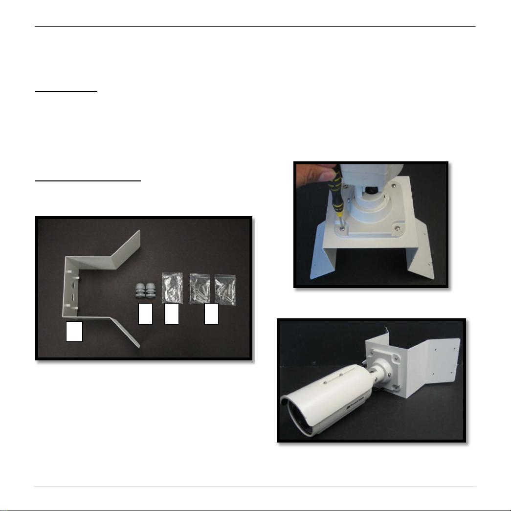
MegaView™v1 Corner Mount Adapter (MD-CRMA) Installation Instructions
TM
v1 Installation Manual
Inside the box:
A. Corner Mount Adapter
B. 2x Compression Fittings
C. Pack of four (4) machine scre ws
D. 2x Packs of four (4) wood screws and four
(4) dry wall anchors
Not included but needed:
• #2 Phillips head screw driver
Image 22
3. Using the screws provided (or other hardware)
to attach the Corner Mount Adapter to an
exterior 90° corner wall as shown in Image 22.
4. To adjust MegaView™ bracket, please
reference “Mounting the Camera”, if needed.
Image 23
NOTE: MD-CRMA also works with MD-WMT2, SVWMT and D4S-WMT
1. Remove Corner Mount Adapter and hardware
from the box.
2. Attach MegaView™ bracket to Corner Mount
Adapter as shown in Image 23.
Image 24
9 | Page
Page 11

Arecont Vision MegaView
TM
v1 Installation Manual
9 | Page
 Loading...