

Page 1
+1.818.937.0700 www.arecontvision.com avsales@arecontvision.com
1080p
5MP
AV02CLD-100
AV05CLD-100
®
Contera
Outdoor Dome
Installation Manual
Page 2

Contera Outdoor Dome | Installation Manual
Table of Contents
About Our Warranty ................................................................................................................................... 3
Global (3 Year) Limited Warranty ............................................................................................................ 3
Camera Overview ....................................................................................................................................... 4
Package Contents ...................................................................................................................................... 5
Installation .................................................................................................................................................. 6
Surface Mount...................................................................................................................................... 10
Wall Mount ........................................................................................................................................... 12
Pendant Mount .................................................................................................................................... 14
Pole Mount ........................................................................................................................................... 16
Corner Mount ....................................................................................................................................... 18
Electrical Box Adapter .......................................................................................................................... 20
SD Card ............................................................................................................................................... 20
Adjusting the Pan, Tilt and Focus ......................................................................................................... 21
Camera Power Up.................................................................................................................................... 23
Alarm I/O Functions .................................................................................................................................. 24
Audio Kit AV-1AK Installation Instructions ................................................................................................. 25
Reset to Factory Default ........................................................................................................................... 26
Camera Discovery, Setup, and Configuration ........................................................................................... 27
Camera Discovery ................................................................................................................................ 27
Web Interface Navigation ..................................................................................................................... 28
Zoom and Focus .................................................................................................................................. 30
Image ................................................................................................................................................... 31
Video & Audio ...................................................................................................................................... 36
Network ............................................................................................................................................... 39
Privacy Mask ........................................................................................................................................ 44
Event .................................................................................................................................................... 45
System Options .................................................................................................................................... 50
Administration ...................................................................................................................................... 51
About ................................................................................................................................................... 53
2
Page 3

Contera Outdoor Dome | Installation Manual
About Our Warranty
Global (3 Year) Limited Warranty
ARECONT VISION warrants to Purchaser (and only Purchaser) (the “Limited Warranty”), that: (a) each
Product shall be free from material defects in material and workmanship for a period of thirty-six (36) months
from the date of shipment (the “Warranty Period”); (b) during the Warranty Period, the Products will materially
conform with the specification in the applicable documentation; (c) all licensed programs accompanying the
Product (the “Licensed Programs”) will materially conform with applicable specifications. ARECONT VISION
warrants to Purchaser (and only Purchaser) (the “Limited Warranty”), that: (a) each Product shall be free from
material defects in material and workmanship for a period of thirty-six (36) months from the date of shipment
(the “Warranty Period”); (b) during the Warranty Period, the Products will materially conform with the
specification in the applicable documentation; (c) all licensed programs accompanying the Product (the
“Licensed Programs”) will materially conform with applicable specifications.
ARECONT VISION warrants to Purchaser (and only Purchaser) (the “Limited Warranty”), that: (a) each
Product shall be free from material defects in material and workmanship for a period of thirty-six (36) months
from the date of shipment (the “Warranty Period”); (b) during the Warranty Period, the Products will materially
conform with the specification in the applicable documentation; (c) all licensed programs accompanying the
Product (the “Licensed Programs”) will materially conform with applicable specifications.
During the Warranty Period, the Products will materially conform with the specification in the applicable
documentation; (c) all licensed programs accompanying the Product (the “Licensed Programs”) will materially
conform with applicable specifications.
3
Page 4

Contera Outdoor Dome | Installation Manual
Contera Outdoor Dome IP Megapixel Cameras
Camera Overview
The Contera
optimum performance. The Contera Outdoor Dome combines a day/night mechanical IR cut filter with an
integrated motorized remote focus and zoom precision iris (P-iris) lens for excellent, optimal image quality.
Regardless of the time of day, the Contera Outdoor Dome is prepared for any lighting condition. For
applications with poor lighting conditions, Enhanced WDR™ (wide dynamic range) at 120dB provides the
best visual balance to shaded and bright light conditions.
For clear color images in low-light, NightView™ offers strong low-light sensitivity for capturing details in
extremely poor-lit scenes. Built-in Smart IR LED illumination automatically adjusts output in response to the
distance of an object in view to prevent over-exposure when the object is very close to the camera. Arecont
Vision® was the first to bring H.264 to the mainstream market and recently developed SNAPstream™
(Smart Noise Adaptation and Processing) technology for reducing bandwidth without impacting image
quality. Today we are proud to offer our next generation H.265 with SNAPstream+™ smart codec capable of
delivering high quality video while saving over 50% of the data rate to reduce or prevent strain on the
network.
The SD card slot supports up to 256GB of storage capacity for convenient onboard storage. The camera’s
power can be supplied via a Power-over- Ethernet (PoE - IEEE 802.3af) compliant network cable connection.
The Contera Outdoor Dome is IP66 rated for both indoor and outdoor applications. All models feature an
impact resistant cast-aluminum housing capable of withstanding the equivalent of 55 kg (120 lbs) of force.
®
Outdoor Dome megapixel camera features 1080p and 5-megapixel (MP) resolution for
The Contera Outdoor Dome is ONVIF (Open Network Video Interface Forum) Profile S and G compliant,
providing interoperability between network video products regardless of manufacturer.
4
Page 5
Contera Outdoor Dome | Installation Manual
CAUTION!
Description
QTY
1. Do not attempt to service a damaged unit yourself. Refer all servicing to qualified service personnel.
2. Wiring methods shall be in accordance with the National Electrical Code/NFPA 70/ANSI, and with all
local codes and authorities having jurisdiction. Wiring should be UL Listed and/or Recognized wire
suitable for the application.
3. Always use hardware e.g. screws, anchors, bolts, locking nuts etc. which are compatible with mounting
surface and of sufficient length and construction to insure a secure mount.
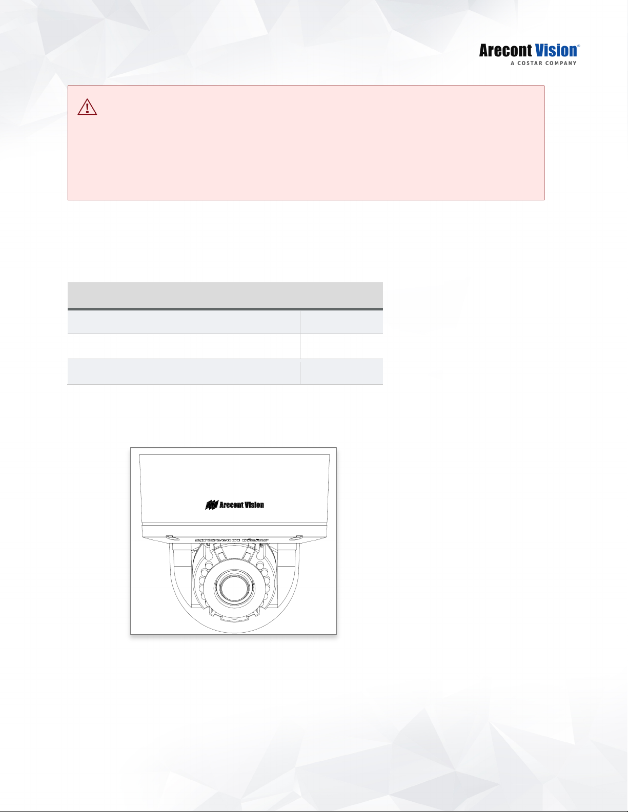
Package Contents
AV02CLD-100/ AV05CLD-100 IP camera 1
Mounting Template 1
Accessory Pack 1
•
AV02CLD-100/ AV05CLD-100
5
Page 6
Contera Outdoor Dome | Installation Manual
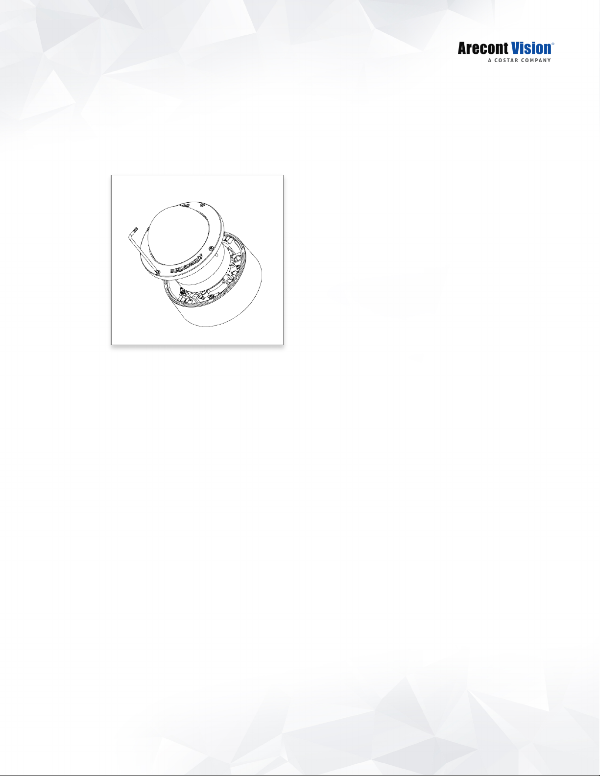
Installation
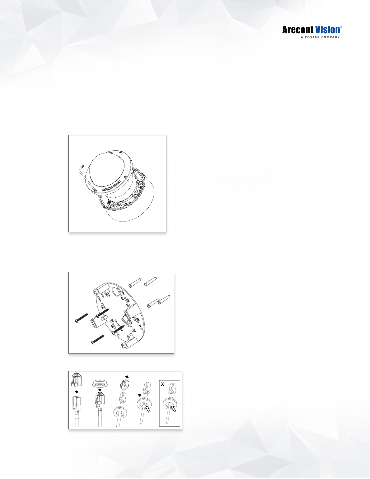
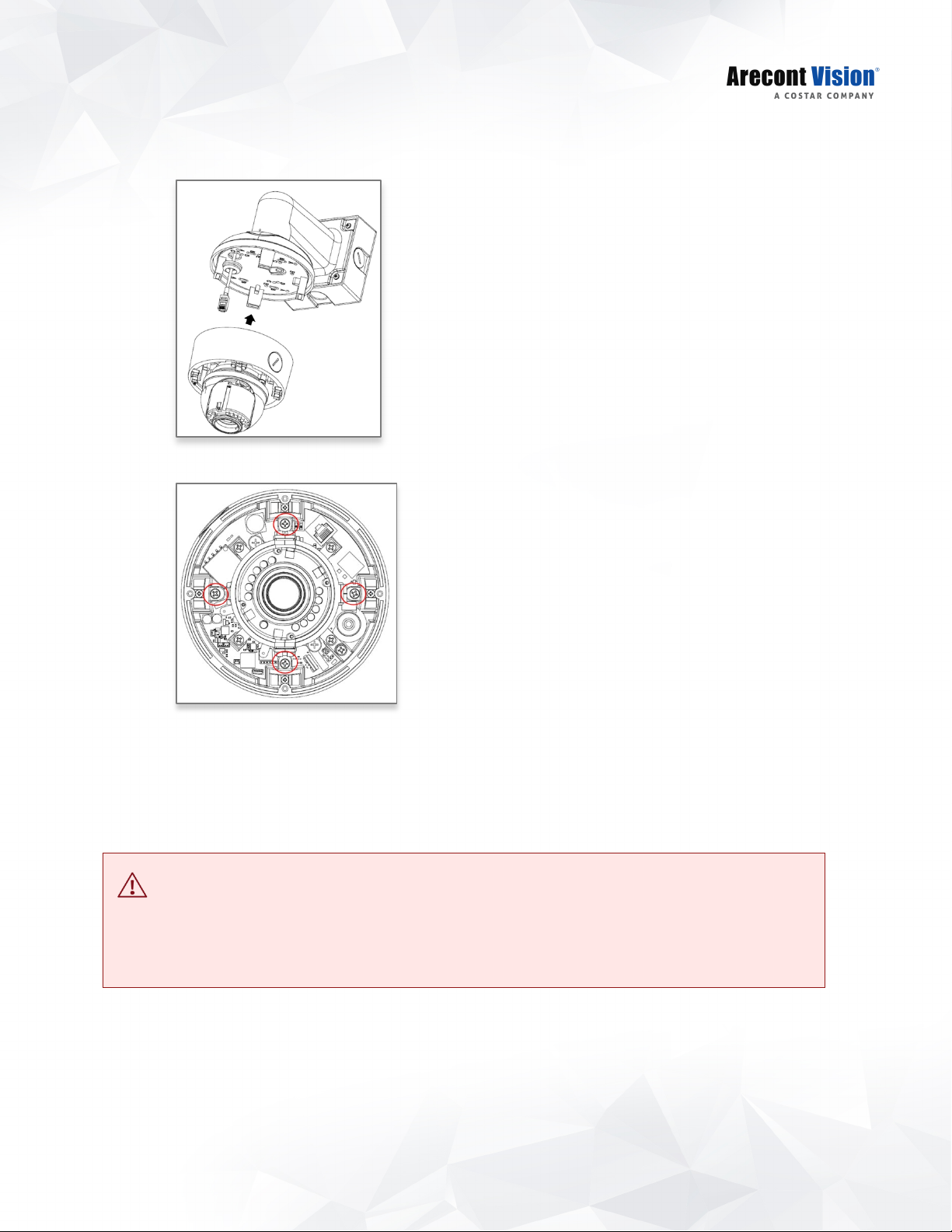
1. Determine a secure location to mount the camera.
2. Use the supplied security L-key, to loosen the four (4) screws securing the dome cover.
3. Remove the dome cover and protective foam. Do not remove screws from the dome cover.
®
The Contera
options such as ceilings, walls, poles or corners.
Outdoor Dome camera has been designed to provide installers with flexible mounting
NOTE: When mounting the camera outdoors or in a wet environment, use of supplied
grommet is recommended. Ensure the grommet properly seated flush with the camera
housing.
NOTE: The camera is suggested to be covered by a minimum 5.6” (14cm) overhang eave.
6
Page 7
Contera Outdoor Dome | Installation Manual
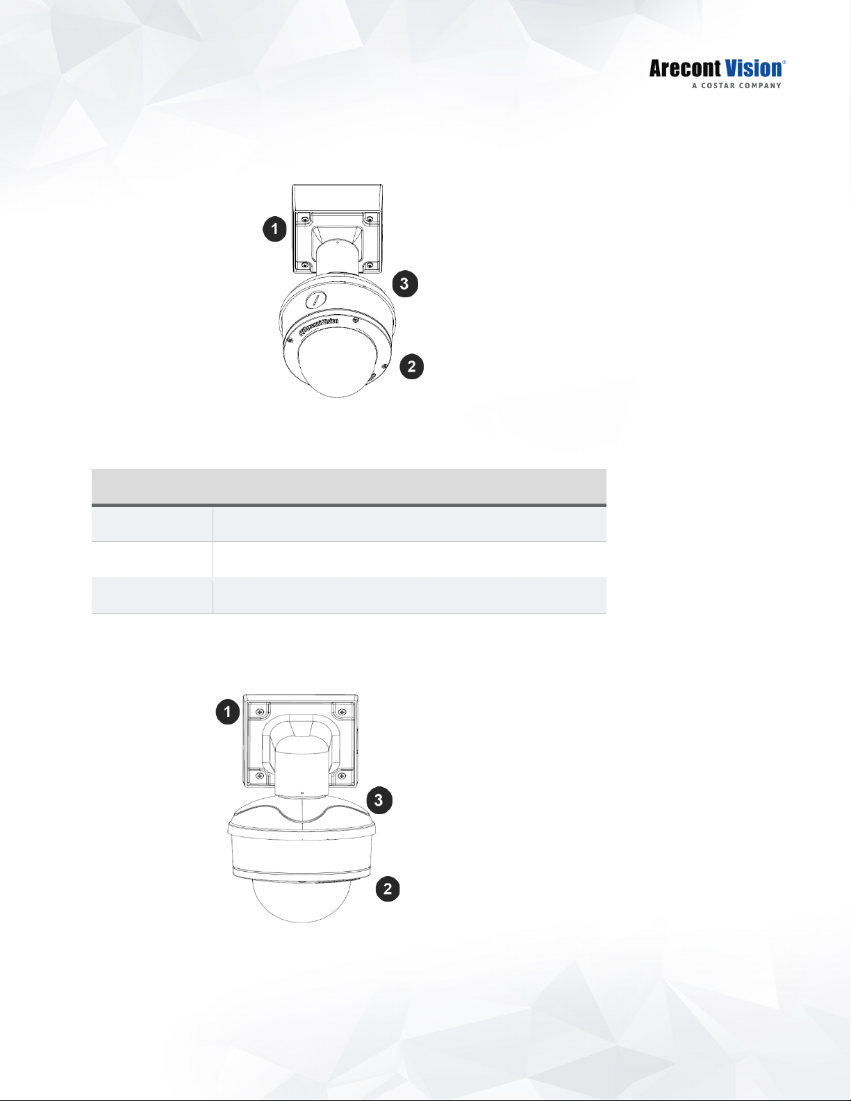
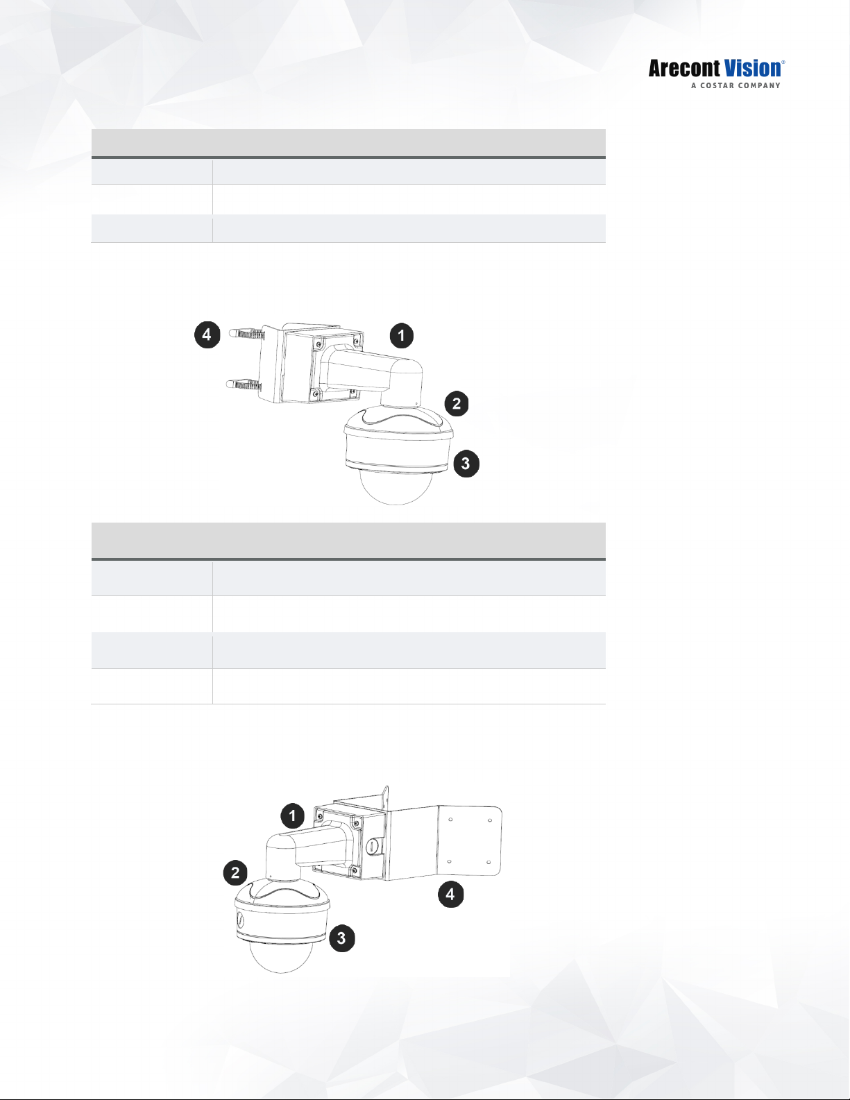
Reference #
Pendant Mount Components Required
Ensure you have the proper compatible mounting parts prior to starting your installation:
Pendant mount
1 Pendant mount (AV-PMJB) with integrated junction box
2 Contera® Outdoor Dome camera
3 MD-CAP-W mounting cap
Wall mount
7
Page 8
Contera Outdoor Dome | Installation Manual
Reference #
Wall Mount Components Required
1
Wall mount (AV-WMJB-W) with integrated junction box
2
Contera® Outdoor Dome camera
3
MD-CAP-W mounting cap
Reference #
Pole Mount Components Required
Pole mount
1 Wall mount (AV-WMJB-W) with integrated junction box
2 MD-CAP-W mounting cap
3 Contera® Outdoor Dome camera
4 AV-PMA corner mount adapter
Corner mount
8
Page 9

Contera Outdoor Dome | Installation Manual
Reference #
Corner Mount Components Required
1 Wall mount (AV-WMJB-W) with integrated junction box
2 MD-CAP-W mounting cap
3 Contera® Outdoor Dome camera
4 AV-CRMA corner mount adapter
9
Page 10
Contera Outdoor Dome | Installation Manual
Surface Mount
The Contera® Outdoor Dome camera can be directly attached onto hard ceilings or walls including wood,
plastic, metal and concrete.
1. Use the template, anchors, and screws provided to prepare the mounting provisions for the camera
installation.
2. Use the supplied security L-key, to loosen the four (4) tamper resistant screws securing the dome
cover. Do not remove screws from the dome cover.
3. Remove the protective foam and discard.
4. Install four supplied dry wall anchors using the supplied mounting template.
5. Align four supplied screws (4pcs #8-16 1¼” tapping screws) with the dry wall anchors and screw
mounting plate into place.
6. Prepare the network cable with the supplied grommet and insertion tool.
10
Page 11
Contera Outdoor Dome | Installation Manual
CAUTION!
NOTE: When mounting the camera outdoors or in a wet environment, use of supplied grommet is
recommended. Ensure the grommet is properly seated flush with the camera housing.
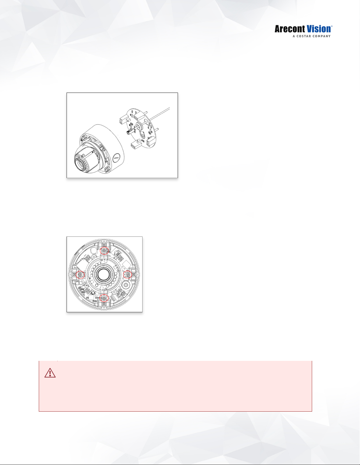
7. Align the hole on the camera with the hole on mounting plate, and install the grommet on camera
housing.
NOTE: If using the side connection of the NPT port, you need to install the supplied grommet
without a through hole on the camera housing, and remove the cap covering the side entrance,
otherwise; leave the cap in place. If using the NPT port, always use Teflon tape around the threads
to ensure proper sealing. The conduit fits ¾” NPT standard. Ensure NPT port is facing downward.
8. Fasten securely four captive screws.
9. Attach the Dome Cover to the Contera
screws.
10. To configure the camera, reference the camera discovery, set-up and configuration section.
The captive screws must be used to properly secure the dome cover and camera housing. Failure to use the
captive fastener may result in serious injury. When mounting the dome cover to the camera housing, ensure
that the gasket is properly seated and not folded. Failure to do so may result in water and dust ingress.
Water damage from improper installation is not covered by the warranty!
®
Outdoor Dome camera and fasten securely four captive
11
Page 12
Contera Outdoor Dome | Installation Manual
Wall Mount
For a proper wall mount installation, the AV-WMJB-W wall mount and MD-CAP-W wall mount cap are
required (sold separately). A wall mount should only be attached onto hard ceilings including wood, plastic,
metal, and concrete.
1. Using the Mounting template, prepare the mounting provisions for the camera installation.
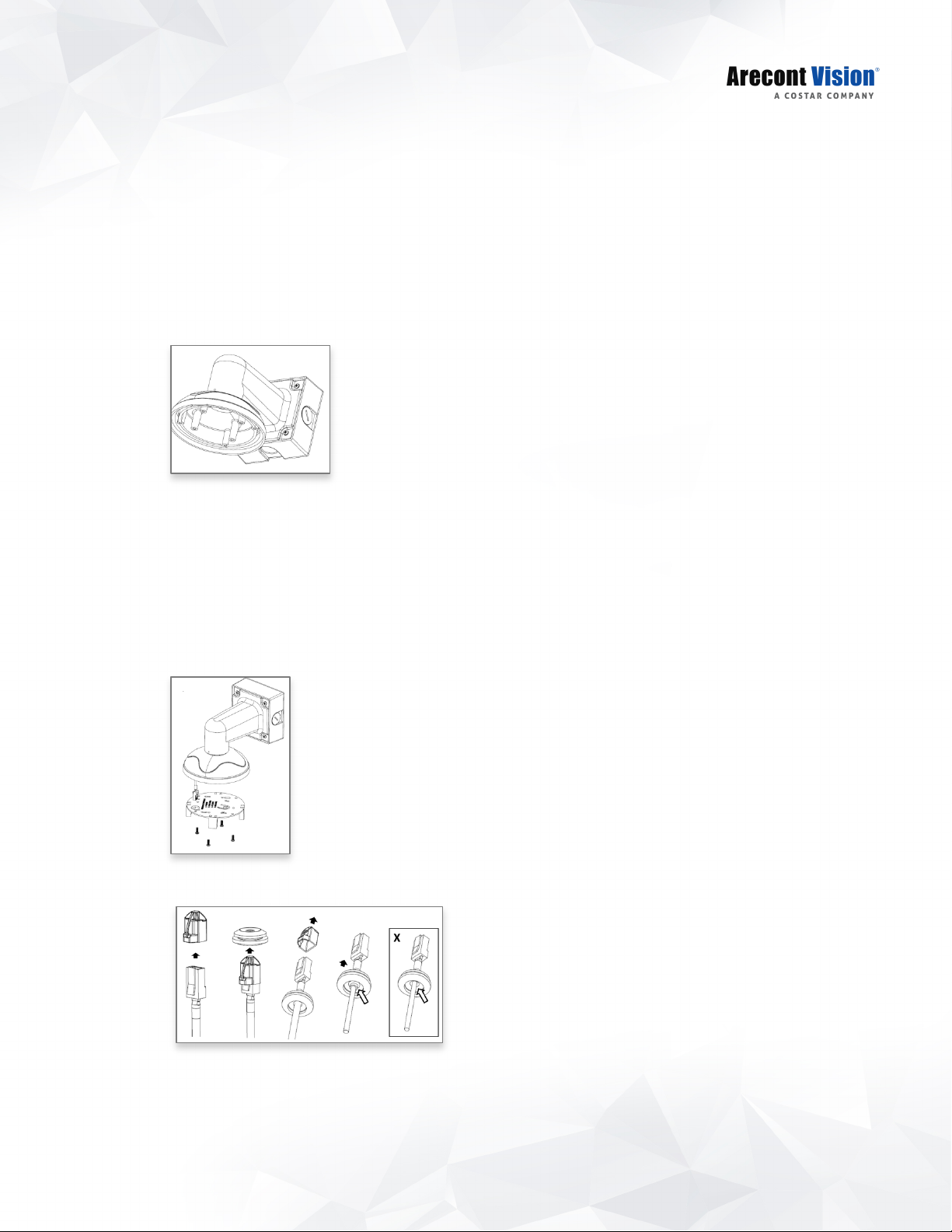
2. Connect wall mount cap and wall mount.
NOTE: The thread size for Top shield, pendant pole and mount is 1.5” NPT.
3. Attach the wall mount to the wall using the four drywall screws provided or any optional hardware
suitable for the mounting surface.
4. Run the Ethernet Cable and outside power cable (if necessary) through the supplied rubber gasket
and then through the wall mount. Ensure the gasket is seated properly.
5. Attach the mounting plate to the MD-CAP-W with the supplied screws.
6. Prepare the network cable with the supplied grommet and insertion tool.
NOTE: When mounting the camera outdoors or in a wet environment, use of supplied grommet is
recommended. Ensure the grommet is properly seated flush with the camera housing.
12
Page 13
Contera Outdoor Dome | Installation Manual
CAUTION!
7. Align the hole on the camera with the hole on mounting plate, and install the grommet on camera
housing.
8. Fasten securely four captive screws.
9. Attach the Dome Cover to the Contera
screws.
10. To configure the camera, reference the camera discovery, set-up and configuration section.
The captive screws must be used to properly secure the dome cover and camera housing. Failure to use the
captive fastener may result in serious injury. When mounting the dome cover to the camera housing, ensure
that the gasket is properly seated and not folded. Failure to do so may result in water and dust ingress.
Water damage from improper installation is not covered by the warranty!
®
Outdoor Dome camera and fasten securely four captive
13
Page 14
Contera Outdoor Dome | Installation Manual
Pendant Mount
For a proper pendant mount installation, the AV-PMJB pendant mount and MD-CAP-W mounting cap are
required (sold separately). A pendant mount should only be attached onto hard ceilings including wood,
plastic, metal, and concrete.
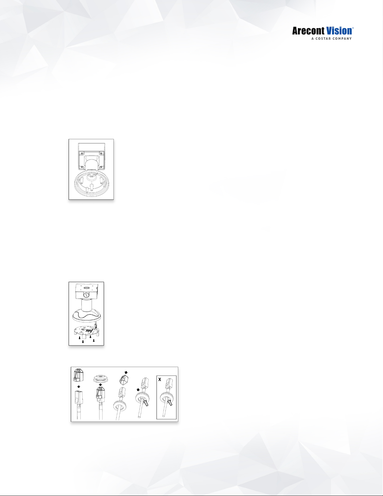
1. Using the Mounting template, prepare the mounting provisions for the camera installation.
2. Connect the cap, pendant pole and mount together.
NOTE: The thread size for Top shield, pendant pole and mount is 1.5” NPT.
3. Attach the pendant mount to the ceiling using the four wood screws provided or any optional
hardware suitable for the mounting surface.
4. Run the Ethernet Cable and outside power cable (if necessary) through the supplied rubber gasket
and then through the wall mount. Ensure the gasket is seated properly.
5. Attach the mounting plate to the MD-CAP-W with the supplied screws.
6. Prepare the network cable with the supplied grommet and insertion tool.
NOTE: When mounting the camera outdoors or in a wet environment, use of supplied grommet is
recommended. Ensure the grommet is properly seated flush with the camera housing.
14
Page 15

Contera Outdoor Dome | Installation Manual
CAUTION!
7. Align the hole on the camera with the hole on mounting plate, and install the grommet on camera
housing.
8. Fasten securely four captive screws.
9. Attach the Dome Cover to the Contera
screws.
10. To configure the camera, reference the camera discovery, set-up and configuration section.
The captive screws must be used to properly secure the dome cover and camera housing. Failure to use the
captive fastener may result in serious injury. When mounting the dome cover to the camera housing, ensure
that the gasket is properly seated and not folded. Failure to do so may result in water and dust ingress.
Water damage from improper installation is not covered by the warranty!
®
Outdoor Dome camera and fasten securely four captive
15
Page 16
Contera Outdoor Dome | Installation Manual
Reference #
Description
Pole Mount
For a pole mount installation, the AV-WMJB-W wall mount, AV-PMA pole mount, and MD-CAP-W
mount cap are required (sold separately). A pole mount should only be attached onto hard ceilings
including wood, plastic, metal, and concrete.
1. Using the Mounting template, prepare the mounting provisions for the camera installation.
2. Connect the wall mount cap and wall mount.
3. Attach the Junction Box Adapter to the Pole Mount Adapter.
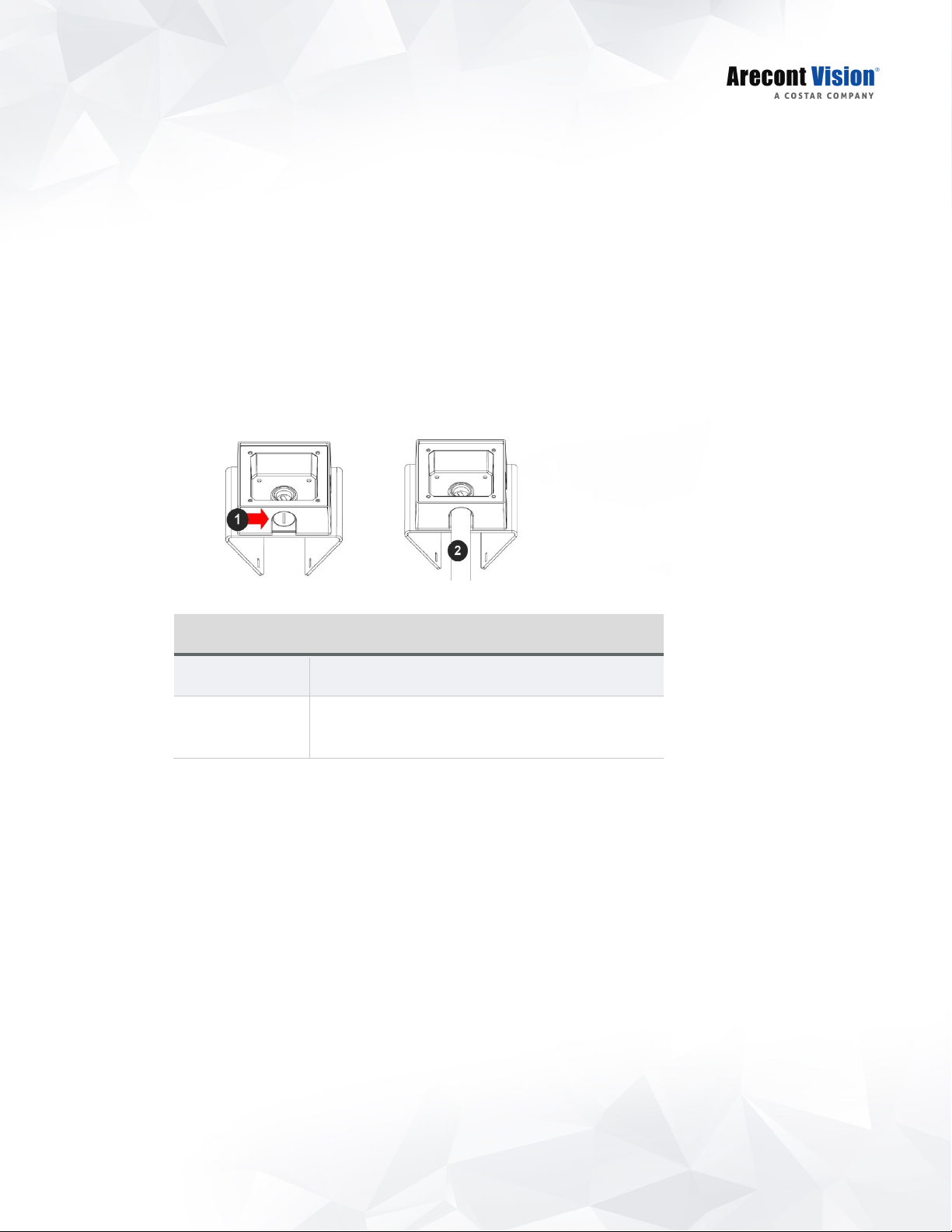
4. Remove the conduit plug on the junction box adapter and connect ¾” NPT conduit to the junction
box adapter.
1 Remove conduit plug
2 Connect ¾” NPT conduit to junction box adapter
(ensure use of water seal tape)
NOTE: Use silicon or water pipe seal tape to make sure no water leakage between conduit
pipe and junction box adapter.
5. Run the Ethernet cable and outside power cable (if necessary) through the Junction Box Adapter.
Ensure the gasket is seated properly.
6. Attach the Wall Mount Adapter (AV-WMJB-W) to the Pole Mount Adapter (AV-PMA) .
16
Page 17

Contera Outdoor Dome | Installation Manual
CAUTION!
Reference #
Description
1 Steel straps with compression screws
2 AV-WMJB-W wall mount
3 MD-CAP-W mount cap
4 Conduit pipe
5 AV-PMA pole mount adapter
6 Apply Teflon water seal tape to the thread of ¾” NPT pipe to
avoid water leakage
7. Use the supplied two Steel Straps to attach the Pole Mount Adapter to the pole and tighten the
compression screws.
8. To attach the camera to the Wall Mount Adapter (AV-WMJB-W), reference the Installation and Wall
Mount section.
9. To configure the camera, reference the camera discovery, set-up and configuration section.
The captive screws must be used to properly secure the dome cover and camera housing.
Failure to use the captive fastener may result in serious injury. When mounting the dome cover to the camera
housing, ensure that the gasket is properly seated and not folded. Failure to do so may result in water and
dust ingress. Water damage from improper installation is not covered by the warranty!
17
Page 18

Contera Outdoor Dome | Installation Manual
Reference #
Description
Corner Mount
For a corner mount installation, the AV-WMJB-W wall mount, AV-CRMA corner mount, and MD-CAP-W
mount cap are required (sold separately). A corner mount should only be attached onto hard corner surfaces
including wood, plastic, metal, and concrete.
1. Using the Mounting template, prepare the mounting provisions for the camera installation.
2. Connect the wall mount cap and wall mount.
3. Attach the Junction Box Adapter to the Corner Mount Adapter.
4. Remove the conduit plug on the junction box adapter and connect ¾” NPT conduit to the junction
box adapter.
1 Remove conduit plug
2 Connect ¾” NPT conduit to junction box adapter
(ensure use of water seal tape)
NOTE: Use silicon or water pipe seal tape to make sure no water leakage between conduit
pipe and junction box adapter.
5. Run the Ethernet cable and outside power cable (if necessary) through the Junction Box Adapter.
Ensure the gasket is seated properly.
6. Attach the Wall Mount Adapter (AV-WMJB-W) to the Corner Mount Adapter (AV-CRMA).
18
Page 19

Contera Outdoor Dome | Installation Manual
CAUTION!
Reference #
Description
1 Attach corner mount adapter to exterior 90 corner wall
2 AV-WMJB wall mount
3 MD-CAP-W mount cap
4 Conduit pipe
5 AV-CRMA corner mount adapter
6 Apply Teflon water seal tape to the thread of ¾” NPT pipe to
avoid water leakage
7. Using the screws provided (or other hardware), attach the Corner Mount Adapter to an exterior 90
degree corner wall.
8. To attach the camera to the Wall Mount Adapter (AV-WMJB), reference the Installation and Wall
Mount section.
9. To configure the camera, reference the camera discovery, set-up and configuration section.
The captive screws must be used to properly secure the dome cover and camera housing.
Failure to use the captive fastener may result in serious injury. When mounting the dome cover to the camera
housing, ensure that the gasket is properly seated and not folded. Failure to do so may result in water and
dust ingress. Water damage from improper installation is not covered by the warranty!
19
Page 20

Contera Outdoor Dome | Installation Manual
Electrical Box Adapter
The mounting plate is used to attach the camera to a common single, double or square electrical box.
1. Using the supplied machine screws, match the mounting holes on the electrical box adapter with the
threaded holes on the electrical box. Ensure every threaded hole is matched with a mounting hole.
2. Attach the electrical box adapter to the user supplied electrical box.
SD Card
Insert an SD card (user supplied) into the SD card slot until it locks in place. The location of the SD card slot
is located on the main board. The SD card can only be set-up via the Web Interface.
Note: Upon insertion or removal of an SD card, the camera must be rebooted.
20
Page 21

Contera Outdoor Dome | Installation Manual
Adjusting the Pan, Tilt and Focus
1. Remove the dome cover by loosening the captive fasteners with the supplied security L-key
screwdriver
2. Power on the camera to adjust the pan, tilt and focus.
3. Remove the shroud from the camera gimbal.
4. Adjust the pan, and tilt/ rotate the lens module to obtain the desired field of view.
21
Page 22

Contera Outdoor Dome | Installation Manual
5. To configure the zoom/focus function, reference the “Zoom and Focus” section of the camera
discovery, set-up and configuration.
6. Install the shroud back on the camera gimbal
22
Page 23

Contera Outdoor Dome | Installation Manual
CAUTION!
CAUTION!
LED
Status
Description
Slow Flashing
Normal operation
Camera Power Up
This product should be installed by a qualified service technician in accordance with the National
Electrical Code (NEC 800 CEC Section 60) or applicable local code. Wiring methods shall be in accordance
with the National Electrical Code/NFPA 70/ANSI, and with all local codes and authorities having jurisdiction.
Wiring should be UL Listed and/or Recognized wire suitable for the application.
Make the connections inside a watertight compartment. Isolate unused power wires individually.
After connections are made, ensure that the watertight compartment is tightly closed and cables and
conduits are properly sealed to prevent ingress of water.
1. Connect the camera to a PoE port on 100Mbps network PoE switch using an Ethernet cable.
2. If the camera is powered by an outside power supply, connect the power wires from the external
power supply (12~48VDC or 24VAC) to the power connector.
3. Connect the PoE switch to your computer’s network port using an Ethernet cable.
Green
None None No Connection
Quick Flashing Link has been established
23
Page 24

Contera Outdoor Dome | Installation Manual
Alarm In (Wet Contact)
Alarm Out (Wet Contact)
V sense
V sense
I sense
Alarm I/O Functions
Connect the Alarm In (DI) connector to the alarm input sensor, and connect Alarm Out (DO) connector to the
alarm output signal. To avoid any damaged, please follow the specification of the part as below:
4.2V±30% 0-80V 50mA (max)
24
Page 25

Contera Outdoor Dome | Installation Manual
Audio Kit AV-1AK Installation Instructions
(Accessory Sold Separately)
1. Run the audio cable connection jack cables through the hole on the bottom of the camera and
connect them to the connectors on the circuit board.
2. Connect the line-in signal to LINEIN (Line In), and connect an active speaker with a built-in amplifier
to LOUT (Line Out) via the in-line jack.
3. Enable Audio function on the camera web interface.
25
Page 26

Contera Outdoor Dome | Installation Manual
Reset to Factory Default
4. Press and hold the reset button for 2 to 5 seconds and release the reset button. The camera has
been reset to the factory default except the network settings.
5. Press and hold the reset button for more than 5 seconds and release the reset button. The camera
has been reset to the factory.
6. Or, user can reset the camera to factory default via camera web interface or AV IP Utility
26
Page 27

Contera Outdoor Dome | Installation Manual
Camera Discovery, Setup, and Configuration
For camera discovery and setup, the AV IP Utility is recommended. The software can be found on the CD
included with your camera or at: http://www.arecontvision.com/softwares.php
The AV IP Utility has the ability to provide multiple discovery options, including broadcast and multicast,
check the status of a camera, change camera settings, import and export camera settings via a .csv file, and
update firmware and/or hardware from virtually anywhere with a network connection.
Whether used for large installations that require an update to multiple settings, or smaller installations where
only one camera needs changed, the AV IP Utility tool is efficient and convenient for mass or single camera
uploads.
®
The AV IP Utility tool is compatible with all Contera
on the CD that came with your camera or available on our website.
cameras. The user manual for the software is included
Camera Discovery
1. Locate and double click the AV IP Utility shortcut on the desktop.
2. When the AV IP Utility is launched, it will automatically search the Contera cameras on the network.
Or, you can also manually search cameras by clicking “Discovery (Multicast)”
3.
You can access the camera web user interface by typing the camera IP address on the preferred
web browser.
27
Page 28

Contera Outdoor Dome | Installation Manual
Web Interface Navigation
The entire menu categories are located on the top of the web interface, and clicking on any one of the
buttons will cause left side of the page to jump to the settings section for the selected button.
The following are the camera settings available on the top of the web interface:
The following are the camera settings available on the top of the web interface:
•
Image
•
Basic Image Settings
•
WDR (Wide Dynamic Range) Settings
•
IR Control
•
OSD (On-Screen Display)
•
ROI (Regions of Interest)
•
Zoom and Focus
•
Zoom/ Focus Control
•
Video & Audio
•
Main Stream Configuration
•
Sub Stream Configuration
•
Third Stream Configuration
•
Audio
•
Network
•
IP Assignment
•
QoS (Quality of Service)
•
UPnP (Universal Plug and Play)
•
RTSP (Real Time Streaming Protocol)
•
DDNS (Dynamic DNS)
•
SNMP (Simple Network Management Protocol)
•
SSL (Secure Sockets Layer)
•
FTP (File Transfer Protocol)
•
802.1x
•
Privacy Mask
•
Event
•
Motion Detection
•
Alarm Handler
•
Digital I/O
•
Tamper Detection
•
FTP Upload Handler
•
SMTP (Simple Mail Transfer Protocol) Notification
•
Network Storage
28
Page 29

Contera Outdoor Dome | Installation Manual
•
System Options
•
Firmware Upgrade
•
Reboot & Restore Settings
•
Date/Time
•
Administration
•
Administrator settings
•
Viewer Management
•
About
•
Support
29
Page 30

Contera Outdoor Dome | Installation Manual
Menu
Feature
Description
Zoom and Focus
Manual Zoom/ Focus:
+20, +5, +1, -20, -5, -1
Enable Auto Focus Zoom Camera will do Auto Focus after changing zoom lens
Full-range Focus Best for scenes that are completely out of focus. The
Short-range Focus Best for scenes that are slightly of out of focus. The
Stop Stops any command in progress.
Reset Zoom and Focus
Position
Numbers indicate the level of Zooming/ focusing in
order to adjust the field-of-view.
group position.
camera automatically scans the full focus range of the
scene to find the best focus position.
camera quickly fine-tunes for a precise focus position.
Resets Zoom and Focus lens groups to zero position
30
Page 31

Contera Outdoor Dome | Installation Manual
Menu
Feature
Description
Image
Brightness
Sharpness
Saturation Controls the color saturation of the image.
Controls the overall brightness of the camera image
and works in conjunction with the exposure controls to
maintain the image brightness.
Controls sharpness and edge definition of the image.
Setting this to lower levels may make overall image
appear a bit softer while causing lines and edges in the
image to look smoother.
Contrast
Hue
Rotate Image:
0, 90, 180, 270
Mirror Image:
Flip Vertically
Flip Horizontally
Auto White Balance Checkbox enables the automatic white balance feature
Manually controls Gamma level (affects the overall
luminance of the image).
Configures the overall hue of the image, the range is 0
~ 100. Increasing the value will adjust the image hue
towards red. Decreasing the value will adjust the image
hue towards blue.
Digitally rotates image 0°, 90°, 180°, or 270°.
Flips the image horizontally (flip left-to-right) or vertically
(flip top-to- bottom). They can be selected at the same
time.
of camera, which will automatically remove unrealistic
color cast so that white color is rendered white in the
image.
31
Page 32

Contera Outdoor Dome | Installation Manual
Menu
Feature
Description
Auto
HDR
Turn off in low light
Turn off in B/W
DWDR
Auto detects bright backlight, glare or high contrast
lighting and automatically selects the WDR level.
Note: WDR enabled will decrease the FPS of 5MP
camera.
Manually adjusts the intensity of backlight
compensation.
Note: WDR enabled will decrease the FPS of 5MP
camera.
Disables WDR backlight compensation when the light
levels drop for better nighttime image quality.
Disables WDR backlight compensation when the
camera is in night mode for better nighttime image
quality.
Digital WDR (DWDR) is to enhance dark areas by
adjusting the gamma value. This will not impact FPS of
5MP camera.
LDR Will not combine long and short exposures into one
frame, resulting in better low light performance.
Auto Exposure Automatically adjusts illumination and exposure values.
Stream Profiles:
Balance Mode
-Slow Shutter
Quality Mode
Balanced Mode: Limits exposure time from 0.1ms to
66ms. The camera will keep highest FPS when Slow
Shutter is unchecked.
Quality Mode: Limits exposure time from 0.1ms to
200ms.
reducing noise and motion blur under most lighting
conditions, but with an increase in motion blur under
low light conditions.
This mode is a good compromise between
32
Page 33

Contera Outdoor Dome | Installation Manual
Moonlight Mode
Custom Exposure Mode
Lighting Compensation
Frequency:
50hz, 60hz, Custom
Moonlight Mode: Limits exposure time from 20ms to
500ms. This mode produces the best image quality
under very low light conditions with the least amount of
image noise. The trade-off is in favor of low noise at
the expense of high motion blur.
Custom Exposure Mod: Enables manual setting of
exposure time between 1 and 80ms. Shorter exposure
times reduces motion blur for applications such as
monitoring fast moving objects and reading license
plates. The trade-off is an increased level of noise. It is
recommended that this mode be used only when there
is constant scene illumination sufficient to provide a
quality image.
Prevents flicker caused by the power line frequency of
lighting. Chooses 50Hz for Europe and China and
60Hz for US and Japan. This parameter will have no
effect when the dominate light is sunlight. Or, user can
select frequency between 5Hz and 255Hz. It will be
enabled when user select “Custom”.
Day/Night Mode
Automatic
Day
Night
Schedule Day Mode
IR control:
Smart IR
On
Off
IR Level
Automatic: Enables the camera to automatically switch
from day mode to night mode. User can define the
switching level from Day to Night or Night to Day.
Day: Forces the camera to stay in day mode.
Night: Forces the camera to stays in night mode.
Schedule Day Mode: User defined times that the
camera remains in night mode.
Smart IR: Automatically adjusts output in response to
the distance of an object in view to prevent
overexposure when the object is very close to the
camera.
On/ Off: Manually turns on or off the IR LED array.
IR Level: Manually adjusts the IR intensity.
33
Page 34

Contera Outdoor Dome | Installation Manual
Transparent
Defog Level Compensates for fog or clouds in the scene in the
scene.
Camera Name Specifies a name for the camera. The maximum length
is 32 characters.
Background
Translucent
Text Color Options are Black, White, Green, or Yellow.
Text Overlay
Off
Date/Time
Camera Name
Camera Name +
Date/Time
Custom Text
Configures the background color of the text overlay.
The options are Translucent (light grey) or Transparent.
There are four content positions (Top Left, Top Right,
Bottom Left and Bottom Right) to display the text
overlay.
Date/ Time: Displays the current date/time. It will force
the camera to synchronize the date/time information.
Camera Name: Displays the camera name you set.
Camera Name + Date/Time: Displays both camera
name and date/time information.
Custom Text: Displays a customized text.
ROI (Regions of Interest) ROI (Regions of Interest) is used to select which areas
will be monitored and recorded with higher image
quality while using lower image quality for other nonROI zones to save bandwidth and storage.
To setup the ROI:
1. Select Main Stream or Sub Stream
2. Enable zones (up to five zones) and select the
desired quality level (High, Medium, or Low).
3. Create the ROI by dragging the mouse over the
live image
4. Press Save Area or Del Area.
34
Page 35

Contera Outdoor Dome | Installation Manual
35
Page 36

Contera Outdoor Dome | Installation Manual
Menu
Feature
Description
Video & Audio
Show Video Type:
Disable Video
MJPEG over HTTP
H.264 over RTP/UDP
Disable Video: Disables live video on the screen.
MJPEG over HTTP: This radio button is the default
browser display option. No plug in is required as most
browsers can decode MJPEG images.
H.264 over RTP/UDP: Displays video using H.264. If
viewing this way for the first time you will see the
following prompt to download the necessary browser
plug –in to display the video in the browser using this
compression.
Fit Video to Window
Control Video with Mouse
No Control
PTZ
ROI Exposure Reference
Scales the full field of view image to fit the browser
window. When in default unselected images will be
displayed in the browser at VGA resolution.
Radio buttons control various functions using the
mouse to select them on screen.
Whichever function is selected can be controlled by left
clicking in the image with the mouse and dragging to
select an image region relevant to the corresponding
control function.
No Control: Disables mouse control of these functions.
PTZ: Zooms in the selected region. Double clicks on
the image will restore the image to default.
ROI Reference: Creates a custom exposure reference
using the selected region to customize backlight.
36
Page 37

Contera Outdoor Dome | Installation Manual
Controls the image size and image cropping features.
Resolution:
Left
Top
Right
Bottom
Left, Top, Right, and Bottom numeric fields set custom
image size cropping and crop area coordinates in
pixels. Supported values are 0 to maximum resolution
in pixels (maximum varies based on the sensor
resolution being cropped)
Video Compression:
H.265
H.264
Resolution
Enable SNAPstream+TM
Variable Bitrate
Radio buttons to select the desired compression.
Radio buttons to select the desired resolution.
Options vary based on the sensor resolution being
used.
Enables the SNAPstream+ feature on camera. This
feature utilizes both Smart GOP and Smart ROI to
reduce bitrate without impacting the image quality.
Smart GOP sets
no moving objects are detected.
Smart ROI will increase the bitrate of moving objects
and make them clearer.
Maintains the Quality setting configured. There may be
variation in the bit rate output from the camera using
this mode.
GOP to automatically increase when
Maximum Bitrate
Maintains variable bit rate control and maintains the
bitrate under the rate limit you set to. It can be set from
64 kbps to 8000 kbps.
37
Page 38

Contera Outdoor Dome | Installation Manual
H.264 image quality setting for variable bit rate control.
Setting a lower value results in higher image quality,
H.264 Quality
Frames Per Seconds
GOP Length
higher value results in lower image quality.
Frame rate adjustment for the camera video stream.
Note: For 5MP models, FPS will be up to 50% of
specified FPS if WDR is enabled.
Note: For 5MP models, if both main and sub stream
set to full resolution, the maximum FPS of the main
stream is up to 15 FPS.
Specifies how many frames between two consecutive
I-Frames.
Video Compression:
MPJEG
Resolution
Frames Per Seconds
Quality:
Low
Mid
High
Audio In
Audio Out
Volume:
High
Middle
Low
The third stream is designed for the live view on web
interface, and the only option of Video Compression is
MPJEG.
The third stream is designed for the live view on web
interface, and the only option of Resolution is VGA.
Frame rate adjustment for the camera video stream.
Adjusts the compression level for JPEG images
Enables the Audio In/ Audio Out features on the
camera.
Specifies the volume level of Audio In/ Audio Out: High,
Middle, or Low.
38
Page 39

Contera Outdoor Dome | Installation Manual
Menu
Feature
Description
Network
DHCP: If checked, the camera will attempt to obtain its
IP address from the DHCP server available on the
network.
IP Assignment:
DHCP
IP Address
Subnet Mask
Default Gateway
Port:
HTTP
Second HTTP Port
HTTPs
Port:
Primary DNS
Secondary DNS
IP Address: Sets the current IP address of the camera.
Subnet Mask: Once set, the camera will use these
mask bits to determine if a destination is from a
different network
Default Gateway: Once set, the camera will use send
traffic to the specified gateway if the destination is on a
different network
HTTP: The port default is 80. It is used to access the
camera via the web browser.
Second HTTP port: Sets an alternative HTTP port. This
port can be useful when the standard HTTP port (80) is
not appropriate for this camera.
HTTPs: The port default is 443. It can be used when
you use HTTPs.
Configures the Primary and Secondary DNS.
IPv6 Settings:
Enable IPv6
IPv6 Address
Address Prefix
Default Route
Router Advertisement
DNS
Enable IPv6: Enables IPv6 function.
Manually configures IPv6 address, Address prefix,
Default route, and DNS server address.
Router Advertisement: Enables Router Advertisement
39
Page 40

Contera Outdoor Dome | Installation Manual
Enable QoS
Video QoS
Management DSCP
Enable UPnP
Port
Enable RTSP Unicast
Stream
Enable RTSP Stream
metadata
Enables quality of service.
Sets DSCP value for video traffic.
Sets DSCP value for non-video traffic.
Enables Universal Plug and Play function.
Configures the port number for stream 1 to stream 3.
The range is 554/1025~65535.
Enables RTSP Unicast for stream 1(Main stream),
stream 2(Sub Stream), and stream 3(Third Stream)
Enables RTSP stream metadata for stream 1(Main
stream), stream 2(Sub Stream), and stream 3(Third
Stream)
Path
Link for external media
players
Enable RTSP Multicast
Stream
Always Multicast
Video IP
Video Port
Configures the pathname for each stream.
Copies the link from here for external media players
Enables RTSP Multicast stream for stream 1(Main
stream), stream 2(Sub Stream), and stream 3(Third
Stream)
Enables the video streams to start multicast steaming
without using RTCP
Configures the multicast address and the port number
to stream video.
40
Page 41

Contera Outdoor Dome | Installation Manual
Audio IP
Audio Port
Meta IP
Meta Port
Path
TTL
Enable DDNS
Host Name
Configures the multicast address and the port number
to stream audio.
*This function is supported depends on models.
Configures the multicast address and the port number
to the HTML meta.
Configures the URL address of the video stream.
Configures the time-to-live threshold of the multicast
datagram before it is discarded by the router.
Enables DDNS service
Specifies the Host name registered with the DDNS
server
DDNS Sever
User Name
Password
Password Confirmation
No SNMP Sever
Selects one of the pubic DDNS severs from the
dropdown menu. Options are DynDNS, NO-IP, and
Twi-DNS.
Specifies the user name of the DDNS account.
Specifies the password of the DDNS account.
Confirms the password of the DDNS account.
Disables SNMP function
SNMP v2c
Enables SNMP version 2 support
41
Page 42

Contera Outdoor Dome | Installation Manual
Install New Certificate
Community String
Trap Configuration:
Address
Community String
SNMP v3
SNMP User
Authentication
Password
Privacy
Password
Specifies the name of the community to access to
SNMP information.
Specifies the destination IP address to send SNMP
trap messages.
Enables SNMP version 3 support.
Specifies the user name of the SNMP v3.
Selects one of the Authentication modes from the
dropdown menu. Options are None, MD5, and SHA.
Specifies the Password for the Authentication.
Selects one of the encryption methods for SNMP v3
from the dropdown menu. Options are DES and AES.
Specifies the Password for the encryption.
Trap Configuration:
Address
Download MIB
Specifies the destination IP address to send SNMP
trap messages.
Clicks to download MIB file for SNMP.
Mode:
Disable
Optional
Certificate
CA Certificate
Client Certificate
Disable: Support for HTTP only.
Optional: Support for HTTP and HTTPs both.
Shows the current status of the Certificate
1. Locate CA Certificate and Client Certificate and
click Upload.
2. Click Install New Certificate to upload the
Certificate.
42
Page 43

Contera Outdoor Dome | Installation Manual
Password
Enable
Confirm
Max. Connection
Protocol
Enables FTP access to the camera.
Note: This function is only available when a SD card is
installed. You can access files in the SD card via FTP.
Specifies and confirms the password to access the
FTP.
Specifies the maximum number of FTP connections to
the IP camera.
The default is None to disable 802.1 x functions. You
can select one of the protocol options from the
dropdown menu. The supported protocols are EAP-
MD5, EAP-TLS, EAP-TTLS or EAP-PEAP.
After the protocol has been selected, manually
configures the username, password and other required
information.
43
Page 44

Contera Outdoor Dome | Installation Manual
Menu
Feature
Description
Privacy Mask
Enable Privacy Mask Creates a privacy mask on the image so the selected
areas will not be visible.
44
Page 45

Contera Outdoor Dome | Installation Manual
Menu
Feature
Description
Event
Enable Turns on and off on-camera motion detection
Extend Enables the extended motion detection and motion
detection zones increase from default 64 to 1024 for
enhanced motion detection sensitivity.
Zone Size Adjusts the size of motion detection zones.
Detail Sets the size of each zone displayed by the motion
detection grid contains sub zones the number of which
is set by the zone size setting up to 32x32 (pixels). This
setting configures the sensitivity of the motion
detection to the size of objects in the image moving
through the zone. Higher values will trigger motion only
for larger objects moving through the zone, lower
values will cause detection of smaller objects in the
zone (increasing sensitivity to smaller size objects
moving through the image).
*This function is supported
depends on models.
Level Threshold Sets the sensitivity to brightness changes between
dark and light objects within each grid zone. As an
example “Detail” will set the size of the object detected
within the zone, “level” sets the duration that
movement must be maintained to trigger motion
detection. Lower settings can increase false motion
alarms caused by image noise, higher settings will
require more movement to trigger a motion event.
Motion Sensitivity Sets the sensitivity to sudden overall brightness
changes in the image.
Enable Alarm Detection Enables Alarm Detection (Alarm In) function.
45
Page 46

Contera Outdoor Dome | Installation Manual
Alarm Schedule Configures the alarm schedule by holding down the
mouse button and clicking the time block to enable the
schedule settings on the selected time. A light blue
color on the time block indicates that the alarm
schedule is enabled, while a light grey color indicates
that the alarm schedule is disabled.
Alternatively, you can manually enter numbers to
configure the hours and minutes from start to end for
all weekdays.
S: Click “S” to set up a 24-hour schedule for a
particular day.
D: Click “D” to clear the previous schedule for a
particular day.
Trigger Alarm Detection When a signal is detected from Alarm in, the Alarm out
will be triggered.
Trigger Motion Detection When a motion detection event is detected, the Alarm
out will be triggered.
Trigger Tamper Detection When a tamper detection event is detected, the Alarm
out will be triggered.
*This function is supported
depends on models.
Type Selects the type: N.O (Normal Open) or N.C (Normal
Close)
Off Time Specifies the alarm duration
Enable Tampering
Detection
Tampering Schedule Configures the alarm schedule by holding down the
Enables Tampering Detection function.
mouse button and clicking the time block to enable the
schedule settings on the selected time. A light blue
color on the time block indicates that the alarm
schedule is enabled, while a light grey color indicates
that the alarm schedule is disabled.
Alternatively, you can manually enter numbers to
configure the hours and minutes from start to end for
all weekdays.
S: Click “S” to set up a 24-hour schedule for a
particular day.
D: Click “D” to clear the previous schedule for a
particular day.
46
Page 47

Contera Outdoor Dome | Installation Manual
Host Address: Specifies the host name or IP address
Host Address: Specifies the host name or IP address
Sensitivity Configures the sensitivity level of Tampering Detection:
High, Medium, and Low.
Remote Server
Host Address
Port
Username
Password
FTP Upload Handler
Enable Trigger Event
SMTP Notification Handler From: Specifies the email address of the sender
of the FTP server.
Port: Specifies the port number of the FTP server.
Username: Specifies the login username of the FTP
server.
Password: Specifies the login password of the FTP
server.
Enables and selects a desired trigger source. The
options are Trigger Alarm Detection*, Trigger Motion
Detection, Trigger Tampering Alarm, and Trigger
Scheduled.
*This function is supported depends on models.
Selects a desired trigger source. The options are
Trigger Alarm Detection, Trigger Motion Detection, and
Trigger Tampering Alarm.
SMTP Server
Host Address
Port
Username
Password
Authentication
Recipient List Specifies the email address to send the email when
of the SMTP server.
Port: Specifies the port number of the SMTP server.
Username: Specifies the login username of the SMTP
server.
Password: Specifies the login password of the SMTP
server.
Authentication: Specifies the authentication mode of
the SMTP sever. The options are NO_AUTH,
SMTP_PLAIN, LOGIN and TLS_TLS.
selected events are triggered by Alarm, Motion, or
Tamper. A maximum of 10 email addresses can be
configured.
47
Page 48

Contera Outdoor Dome | Installation Manual
Login Certificate Specifies the login Username and Password for the
network storage sever.
Recipient Setup
Network Storage Status
Network Address
Folder Name
Record Type
Mount and Remove
Network Storage
Network Storage Status: Displays the current status of
the connection with the network storage server.
( not_mounted or ok)
Network Address: Specifies the IP address of the
network storage server.
Folder Name: Specifies the folder name on the network
storage server.
Recoding Type: Specifies the desired action when an
event is triggered. The options are Snapshot and
Video.
Mount: Sets up a network connection with the network
storage server. All the video recordings or snapshots
from event triggers will be uploaded to the network
storage server. After the setting is complete, the
Network Storage Status field will display “ok”.
Remove: Deletes the previous setting. After the setting
is removed, the Network Storage Status field will
display “not_mounted”.
Network Storage Handler Enables and selects a desired trigger source. The
options are Trigger Alarm Detection*, Trigger Motion
Detection, Trigger Tampering Alarm, and Trigger
Scheduled.
*This function is supported depends on models.
Enable Enables and selects a desired trigger source. The
options are Trigger Alarm Detection*, Trigger Motion
Detection, Trigger Tampering Alarm, and Manual
Record.
*This function is supported depends on models.
48
Page 49

Contera Outdoor Dome | Installation Manual
SD Card Information
Available Storage
Format SD Card
Usage
Status
Overwrite when storage full
Record Type
Available Storage: Displays the available storage of the
SD card if it is installed.
Format SD Card: Erases all the data stored on the SD
Card.
Usage: Displays the total storage that has been used
now.
Status: Displays the status whether the SD card is
installed or not. ( not_mounted or ok)
Overwrite when storage full: Enables overwriting the
SD card if the storage is full.
Recoding Type: Specifies the desired action to record
a stream. The options are Snapshot and Video.
49
Page 50

Contera Outdoor Dome | Installation Manual
Menu
Feature
Description
NTP Server: Synchronizes the date/time information
System Options
Firmware Upgrade Clicks Browse to choose the firmware upgrade file,
Download Log Records all the status information of the camera in list
and then clicks Upgrade.
format. Downloads the log file to the computer as a
text file.
Note: The log file is protected by a password. Please
contact with Arecont Vision technical support team.
Reboot & Restore Settings
Reboot the Camera
Restore Factory Default
Settings Except Network
Settings
Restore to Factory Default
Settings
Get Time from
NTP Server
Computer System
Reboot the Camera: Reboots the camera.
Restore Factory Default Settings Except Network
Settings: Restores all settings to factory default except
the network settings.
Restore to Factory Default Settings: Restores all
settings to factory default.
with defined NTP server. After setting up the desired
Time zone and NTP Server, clicks Apply NTP Server
Configuration.
Note: Please make sure set up appropriate gateway
before configuring the NTP server.
Computer System: Synchronizes the date/time
information with current computer’s date/time. Once
this option selected, clicks Update Time from the
computer.
Time Zone Specifies the country/ city of the time zone from the
drop down menu.
NTP Server Specifies the desired NTP server
50
Page 51

Contera Outdoor Dome | Installation Manual
Menu
Feature
Description
Administration
Access Control Passwords can be up to 16 letters, digits and symbols,
excluding following symbols for passwords without
encoding # % & ' " < > / [ ] { } _ ( ) = . + ,
Administrator
Username
Admin Password
Confirmation
Set/ Erase
Username: The username of Administrator is admin
and cannot be changed.
Admin: full access to all camera settings and live video.
Admin Password: Specifies the password
administrator.
Confirmation: Re-enters the password for the
password validation.
Set/ Erase: Saves or removes the password.
Note: If admin password was set but has been lost, it
can be erased by AV IP Utility using the key file.
Please contact Arecont Vision technical support to
obtain the key file required to perform this function. Or,
if the camera has a reset button, you can also reset to
Factory default for removing the password.
for the
51
Page 52

Contera Outdoor Dome | Installation Manual
Viewer Management
User List
User Name
Viewer Password
Confirmation
Access Level
Set/ Erase
User List: Displays current user accounts created on
the camera. Clicks New User/ Delete User to create or
remove a user account.
User Name: Specifies the user name. It must be at
least five and up to sixteen characters.
Viewer Password: Specifies the password for the
viewer.
Confirmation: Re-enters the password for the
password validation.
Access Level: Defines the authorization level for the
user: Admin or Viewer.
Set/ Erase: Save or removes the password.
52
Page 53

Contera Outdoor Dome | Installation Manual
Menu
Feature
Description
Menu
Feature
Description
About
About Displays the information of the camera: Model Name,
Firmware, Serial Number, and MAC Address.
Support
Support Provides several useful hyperlinks for users who would
like to get more information of the camera.
53
Page 54

+1.818.937.0700 www.arecontvision.com avsales@arecontvision.com
Rev 001.001
© 2018 Arecont Vision
All rights reserved. No part of this publication may be reproduced by any
means without written permission from Arecont Vision.
The information in this publication is believed to be accurate in all
respects. However, Arecont Vision cannot assume responsibility for any
consequences resulting from the use thereof.
The information contained herein is subject to change without notice.
Revisions or new editions to this publication may be issued to
incorporate such changes.
Page 55

Mounting Template
E
E
E
165mm
E
165mm
 Loading...