


 Loading...
12Gb/s SAS RAID Cards
ARC-1883 Series
(PCIe 3.0 to 12Gb/s SAS RAID Controllers)
User Manual
Version: 1.4
Issue Date: July, 2016
Copyright and Trademarks
The information regarding products in this manual is subject to change without prior notice and does not represent a commitment on the part of the vendor, who assumes no liability or responsibility for any errors that may appear in this manual. All brands and trademarks are the properties of their respective owners. This manual contains materials protected under International Copyright Conventions. All rights reserved. No part of this manual may be reproduced in any form or by any means, electronic or mechanical, including photocopying, without the written permission of the manufacturer and the author.
FCC Statement
This equipment has been tested and found to comply with the limits for a Class B digital device, pursuant to part 15 of the FCC Rules. These limits are designed to provide reasonable protection against interference in a residential installation. This equipment generates, uses, and can radiate radio frequency energy and, if not installed and used in accordance with the instructions, may cause harmful interference to radio communications. However, there is no guarantee that interference will not occur in a particular installation.
Manufacturer’s Declaration for CE Certification
We confirm ARC-1883 has been tested and found compliant with the requirements in the council directive relating to the EMC Directive
2004/108/EC. Regarding to the electromagnetic compatibility, the following standards were applied:
EN 55022: 2006, Class B |
EN 55024:1998+A1:2001=A2:2003 |
EN 61000-3-2: 2006 |
IEC61000-4-2: 2001 |
EN 61000-3-3: 1995+A1: 2001+A2: 2005 |
IEC61000-4-3: 2006 |
|
IEC61000-4-4: 2004 |
|
IEC61000-4-5: 2005 |
|
IEC61000-4-6: 2006 |
|
IEC61000-4-8: 2001 |
|
IEC61000-4-11: 2004 |
|
Contents |
|
1. Introduction............................................................... |
10 |
|
1.1 |
Overview........................................................................ |
10 |
1.2 |
Features......................................................................... |
12 |
2. Hardware Installation................................................ |
16 |
|
2.1 |
Before You First Installing................................................. |
16 |
2.2 |
Board Layout.................................................................. |
16 |
2.3 |
Installation..................................................................... |
22 |
2.4 |
SAS Cables..................................................................... |
31 |
2.4.1 Mini SAS HD SFF-8643 to 4xSATA Cable ........................ |
31 |
|
2.4.2 Mini SAS HD SFF-8643 to 4xSFF-8482 Cable................... |
32 |
|
2.4.3 Mini SAS HD SFF-8643 Cable........................................ |
32 |
|
2.4.4 Mini SAS HD SFF-8644 Cable ....................................... |
33 |
|
2.5 |
LED Cables..................................................................... |
33 |
2.6 |
Hot-plug Drive Replacement.............................................. |
37 |
2.6.1 Recognizing a Drive Failure........................................... |
37 |
|
2.6.2 Replacing a Failed Drive............................................... |
37 |
|
2.7 |
Summary of the installation.............................................. |
38 |
3. McBIOS RAID Manager............................................... |
41 |
|
3.1 |
Starting the McBIOS RAID Manager.................................... |
41 |
3.2 |
McBIOS RAID manager..................................................... |
42 |
3.3 |
Configuring Raid Sets and Volume Sets............................... |
43 |
3.4 |
Designating Drives as Hot Spares...................................... |
43 |
3.5 |
Using Quick Volume /Raid Setup Configuration..................... |
44 |
3.6 |
Using Raid Set/Volume Set Function Method........................ |
45 |
3.7 |
Main Menu ..................................................................... |
47 |
3.7.1 Quick Volume/Raid Setup............................................. |
48 |
|
3.7.2 Raid Set Function........................................................ |
52 |
|
3.7.2.1 Create Raid Set ..................................................... |
53 |
|
3.7.2.2 Delete Raid Set...................................................... |
54 |
|
3.7.2.3 Expand Raid Set..................................................... |
55 |
|
3.7.2.4 Offline Raid Set...................................................... |
56 |
|
3.7.2.5 Activate Raid Set.................................................... |
57 |
|
3.7.2.6 Create Hot Spare................................................... |
58 |
|
3.7.2.7 Delete Hot Spare.................................................... |
58 |
|
3.7.2.8 Rescue Raid Set .................................................... |
59 |
|
3.7.2.9 Raid Set Information............................................... |
60 |
|
3.7.3 Volume Set Function.................................................... |
60 |
|
3.7.3.1 Create Volume Set (0/1/10/3/5/6)............................ |
61 |
• Volume Name................................................................. |
63 |
• Capacity........................................................................ |
64 |
• Stripe Size..................................................................... |
66 |
• SCSI ID......................................................................... |
67 |
• Cache Mode................................................................... |
68 |
• Write Protect.................................................................. |
68 |
• Tag Queuing................................................................... |
69 |
3.7.3.2 Create Raid30/50/60 (Volume Set 30/50/60)............. |
69 |
3.7.3.3 Delete Volume Set.................................................. |
70 |
3.7.3.4 Modify Volume Set.................................................. |
71 |
3.7.3.5 Check Volume Set.................................................. |
73 |
3.7.3.6 Stop Volume Check................................................ |
73 |
3.7.3.7 Display Volume Set Info.......................................... |
73 |
3.7.4 Physical Drives........................................................... |
74 |
3.7.4.1 View Drive Information .......................................... |
75 |
3.7.4.2 Create Pass-Through Disk........................................ |
75 |
3.7.4.3 Modify Pass-Through Disk........................................ |
76 |
3.7.4.4 Delete Pass-Through Disk........................................ |
76 |
3.7.4.5 Set Disk To Be Failed.............................................. |
76 |
3.7.4.7 Identify Selected Drive............................................ |
77 |
3.7.4.6 Activate Failed Disk................................................ |
77 |
3.7.4.8 Identify Enclosure.................................................. |
78 |
3.7.5 Raid System Function.................................................. |
78 |
3.7.5.1 Mute The Alert Beeper............................................ |
79 |
3.7.5.2 Alert Beeper Setting............................................... |
79 |
3.7.5.3 Change Password................................................... |
80 |
3.7.5.4 JBOD/RAID Function............................................... |
81 |
3.7.5.5 Background Task Priority......................................... |
82 |
3.7.5.6 SATA NCQ Support................................................. |
82 |
3.7.5.7 HDD Read Ahead Cache.......................................... |
83 |
3.7.5.8 Volume Data Read Ahead........................................ |
84 |
3.7.5.9 Hdd Queue Depth Setting........................................ |
84 |
3.7.5.10 Empty HDD Slot LED............................................. |
85 |
3.7.5.11 Controller Fan Detection........................................ |
86 |
3.7.5.12 Auto Activate Raid Set........................................... |
86 |
3.7.5.13 Disk Write Cache Mode.......................................... |
87 |
3.7.5.14 Write Same Support.............................................. |
87 |
3.7.5.15 Capacity Truncation.............................................. |
88 |
3.7.6 More System Functions................................................ |
89 |
3.7.6.1 Smart Option For HDD............................................ |
89 |
3.7.6.2 Smart Polling Interval............................................. |
90 |
3.7.6.3 Hot Plugged Disk For Rebuilding............................... |
91 |
|
3.7.7 HDD Power Management.............................................. |
92 |
|
3.7.7.1 Stagger Power On.................................................. |
92 |
|
3.7.7.2 Time to Hdd Low Power Idle ................................... |
93 |
|
3.7.7.3 Time To Low RPM Mode .......................................... |
94 |
|
3.7.7.4 Time To Spin Down Idle Hdd ................................... |
94 |
|
3.7.8 Ethernet Configuration ................................................ |
95 |
|
3.7.8.1 DHCP Function....................................................... |
95 |
|
3.7.8.2 Local IP address..................................................... |
96 |
|
3.7.8.3 HTTP Port Number.................................................. |
97 |
|
3.7.8.4 Telnet Port Number................................................. |
97 |
|
3.7.8.5 SMTP Port Number................................................. |
98 |
|
3.7.8.6 Ethernet Address.................................................... |
98 |
|
3.7.9 Alert By Mail Config .................................................... |
99 |
|
3.7.10 View System Events.................................................. |
99 |
|
3.7.11 Clear Events Buffer.................................................. |
100 |
|
3.7.12 Hardware Monitor.................................................... |
100 |
|
3.7.13 System Information................................................. |
101 |
|
4. Driver Installation.................................................... |
102 |
|
4.1 |
Creating the Driver Diskettes.......................................... |
102 |
4.2 |
Driver Installation for Windows........................................ |
104 |
4.2.1 Installing Windows on a RAID Volume.......................... |
104 |
|
4.2.2 Installing Controller on an Existing Windows ................ |
105 |
|
4.2.3 Uninstall controller from Windows .............................. |
107 |
|
4.3 |
Driver Installation for Linux............................................. |
107 |
4.4 |
Driver Installation for FreeBSD........................................ |
108 |
4.5 |
Driver Installation for Solaris........................................... |
109 |
4.6 |
Driver Installation for Mac OS X....................................... |
109 |
4.6.1 Installation Procedures.............................................. |
109 |
|
4.6.2 Making Volume Sets Available to Mac OS X................... |
112 |
|
5. ArcHTTP Proxy Server Installation........................... |
114 |
|
5.1 |
For Windows................................................................. |
115 |
5.2 |
For Linux...................................................................... |
116 |
5.3 |
For FreeBSD.................................................................. |
118 |
5.4 |
For Solaris 10 ............................................................... |
118 |
5.5 |
For Mac OS X................................................................ |
119 |
5.6 |
ArcHTTP Configuration.................................................... |
119 |
6. Web Browser-based Configuration .......................... |
124 |
|
6.1 |
Start-up McRAID Storage Manager .................................. |
124 |
• Start-up from Windows/Mac Local Administration ........ |
125 |
|
• Start-up from Local Administration .............................. |
125 |
|
• Start-up from Ethernet Port (Out-of-Band) .................. |
126 |
6.2 McRAID Storage Manager............................................... |
127 |
6.3 Main Menu ................................................................... |
128 |
6.4 Quick Function.............................................................. |
128 |
6.5.1 Create Raid Set ....................................................... |
129 |
6.5.2 Delete Raid Set......................................................... |
130 |
6.5.3 Expand Raid Set....................................................... |
130 |
6.5.4 Offline Raid Set......................................................... |
131 |
6.5.5 Rename Raid Set...................................................... |
132 |
6.5.6 Activate Incomplete Raid Set...................................... |
132 |
6.5.7 Create Hot Spare...................................................... |
133 |
6.5.8 Delete Hot Spare...................................................... |
134 |
6.5.9 Rescue Raid Set........................................................ |
134 |
6.6 Volume Set Functions..................................................... |
135 |
6.6.1 Create Volume Set (0/1/10/3/5/6) ............................. |
135 |
6.6.2 Create Raid30/50/60 (Volume Set 30/50/60)................ |
140 |
6.6.3 Delete Volume Set.................................................... |
141 |
6.6.4 Modify Volume Set.................................................... |
141 |
6.6.4.1 Volume Growth.................................................... |
142 |
6.6.4.2 Volume Set Migration............................................ |
143 |
6.6.4.3 Volume Write Protection........................................ |
143 |
6.6.5 Check Volume Set..................................................... |
144 |
6.6.6 Schedule Volume Check............................................. |
144 |
6.6.7 Stop Volume Set Check.............................................. |
145 |
6.6.8 Download Volume Key File.......................................... |
145 |
6.7 Physical Drive ............................................................... |
146 |
6.7.1 Create Pass-Through Disk.......................................... |
146 |
6.7.2 Modify Pass-Through Disk........................................... |
146 |
6.7.3 Delete Pass-Through Disk........................................... |
147 |
6.7.4 Clone Disk............................................................... |
147 |
6.7.4.1 Clone And Replace................................................ |
148 |
6.7.4.2 Clone Only ......................................................... |
149 |
6.7.5 Abort Cloning........................................................... |
149 |
6.7.6 Set Disk To Be Failed................................................. |
149 |
6.7.7 Activate Failed Disk................................................... |
149 |
6.7.8 Identify Enclosure..................................................... |
150 |
6.7.9 Identify Drive........................................................... |
150 |
6.8 System Controls............................................................ |
151 |
6.8.1 System Config.......................................................... |
151 |
• System Beeper Setting.................................................. |
151 |
• Background Task Priority................................................ |
151 |
• JBOD/RAID Configuration............................................... |
151 |
• SATA NCQ Support........................................................ |
152 |
• HDD Read Ahead Cache................................................. |
152 |
• Volume Data Read Ahead .............................................. |
152 |
• HDD Queue Depth ....................................................... |
152 |
• Empty HDD Slot LED..................................................... |
152 |
• CPU Fan Detection........................................................ |
153 |
• SES2 Support............................................................... |
153 |
• Max Command Length................................................... |
153 |
• Auto Activate Incomplete Raid........................................ |
153 |
• Disk Write Cache Mode.................................................. |
153 |
• Write Same For Initialization.......................................... |
154 |
• Hot Plugged Disk For Rebuilding...................................... |
154 |
• PCIE Gen3................................................................... |
154 |
• Disk Capacity Truncation Mode....................................... |
154 |
• Smart Option For HDD................................................... |
155 |
• Smart Polling Interval.................................................... |
155 |
6.8.2 Advanced Configuration............................................. |
156 |
6.8.3 HDD Power Management............................................ |
161 |
6.8.3.1 Stagger Power On Control..................................... |
161 |
6.8.3.2 Time to Hdd Low Power Idle ................................. |
162 |
6.8.3.3 Time To Hdd Low RPM Mode .................................. |
162 |
6.8.3.4 Time To Spin Down Idle HDD................................. |
162 |
6.8.3.5 SATA Power Up In Standby ................................... |
162 |
6.8.4 Ethernet Configuration .............................................. |
163 |
6.8.5 Alert By Mail Configuration ....................................... |
164 |
6.8.6 SNMP Configuration................................................... |
165 |
6.8.7 NTP Configuration .................................................... |
165 |
6.8.8 View Events/Mute Beeper........................................... |
166 |
6.8.9 Generate Test Event.................................................. |
167 |
6.8.10 Clear Events Buffer.................................................. |
167 |
6.8.11 Modify Password..................................................... |
167 |
6.8.12 Update Firmware .................................................... |
168 |
6.9 Information.................................................................. |
169 |
6.9.1 Raid Set Hierarchy.................................................... |
169 |
6.9.1.1 Hdd Xfer Speed.................................................... |
169 |
6.9.2 SAS Chip Information................................................ |
170 |
6.9.3 System Information.................................................. |
171 |
6.9.4 Hardware Monitor..................................................... |
171 |
Appendix A .................................................................. |
172 |
Upgrading Flash ROM Update Process.................................... |
172 |
Appendix B................................................................... |
176 |
Flash-based Backup Module (ARC-1883-BAT/CAP)................... |
176 |
Appendix C................................................................... |
181 |
Battery Backup Module (ARC-6120BA-T121-12G).................... |
181 |
Appendix D.................................................................. |
185 |
SNMP Operation & Installation.............................................. |
185 |
Appendix E................................................................... |
196 |
Event Notification Configurations......................................... |
196 |
A. Device Event.............................................................. |
196 |
B. Volume Event............................................................. |
197 |
C. RAID Set Event........................................................... |
197 |
D. Hardware Monitor Event............................................... |
198 |
Appendix F................................................................... |
199 |
RAID Concept..................................................................... |
199 |
RAID Set.......................................................................... |
199 |
Volume Set...................................................................... |
199 |
Ease of Use Features......................................................... |
200 |
• Foreground Availability/Background Initialization............... |
200 |
• Online Array Roaming.................................................... |
200 |
• Online Capacity Expansion............................................. |
200 |
• Online Volume Expansion............................................... |
203 |
High availability.................................................................. |
203 |
• Global/Local Hot Spares................................................... |
203 |
• Hot-Swap Disk Drive Support........................................... |
204 |
• Auto Declare Hot-Spare .................................................. |
204 |
• Auto Rebuilding.............................................................. |
205 |
• Adjustable Rebuild Priority............................................... |
205 |
High Reliability.................................................................... |
206 |
• Hard Drive Failure Prediction............................................ |
206 |
• Auto Reassign Sector...................................................... |
206 |
• Consistency Check.......................................................... |
207 |
Data Protection................................................................... |
208 |
• Battery Backup .............................................................. |
208 |
• Recovery ROM................................................................ |
208 |
Appendix G.................................................................. |
209 |
Understanding RAID........................................................... |
209 |
RAID 0............................................................................ |
209 |
RAID 1............................................................................ |
210 |
RAID 10(1E)..................................................................... |
211 |
RAID 3............................................................................ |
211 |
RAID 5............................................................................ |
212 |
RAID 6............................................................................ |
213 |
RAID x0........................................................................... |
213 |
JBOD............................................................................... |
214 |
Single Disk (Pass-Through Disk).......................................... |
214 |

INTRODUCTION
1. Introduction
This section presents a brief overview of the 12Gb/s SAS RAID controller, ARC-1883 series. (PCIe 3.0 to 12Gb/s SAS RAID controllers)
1.1 Overview
The 12Gb/s SAS interface supports both 12Gb/s SAS disk drives for data-intensive applications and 6Gb/s SATA drives for low-cost bulk storage of reference data. The ARC-1883 family includes 8 ports low profile as well as 12/16/24 internal ports with additional 4 external ports models. The ARC-1883LP/1883i/1883x support eight 12Gb/s SAS ports via one internal & one external/two internal/two external Mini SAS HD connector. The ARC-1883ix-12/16/24 attaches directly to SATA/SAS midplanes with 3/4/6 Mini SAS HD
SFF-8643 internal connector or increase capacity using one additional Mini SAS HD SFF-8644 external connector. When used with 12Gb/s SAS expanders, the controller can provide up to (256) devices through one or more 12Gb/s SAS JBODs, making it an ideal solution for enterprise-class storage applications that called for maximum configuration flexibility.
ARC-1883i/LP/x 12Gb/s RAID controllers are low-profile PCIe cards, ideal for 1U and 2U rack-mount systems. These controllers utilize the same RAID kernel that has been field-proven in existing external RAID controller products, allowing Areca to quickly bring stable and reliable PCIe 3.0 12Gb/s SAS RAID controllers to the market.
Unparalleled Performance for 12Gb/s SAS
The 12Gb/s SAS RAID controllers raise the standard to higher performance levels with several enhancements including new high performance 1.2 GHz dual core ROC processor, a DDR3-1866 memory architecture and high performance PCIe 3.0 interface bus interconnection. The low profile controllers by default support on-board 2G of ECC DDR3-1866 SDRAM memory. ARC-1883ix-12/16/24 RAID controllers each include one 240-pin DIMM socket with default 2GB
DDR3-1866, single rank, 1Rx8, upgrade to 8GB or 8GB DDR31600, dual rank, 2Rx8, ECC SDRAM. The 12Gb/s SAS is designed for backward compatibility with 6Gb/s and 3Gb/s SAS/SATA hard
10
INTRODUCTION
drives. Regardless of the drive speed, 12Gb/s SAS RAID controllers will provide maximum read/write performance improvements for the most performance-hungry database and IT applications.
The ARC-1883ix includes one 12Gb/s SAS expander that incorporates the latest enhancements in SAS along with new LSI DataBolt bandwidth optimizer technology. This is designed to help facilitate the industry transition to 12Gb/s SAS-enabled systems by allowing users to take advantage of 12Gb/s speeds while utilizing existing 6Gb/s drives and backplanes. Using DataBolt, the ARC-1883ix buffers 6Gb/s data and then transfers it out to the host at 12Gb/s speeds in order to match the bandwidth between faster hosts and slower SAS or SATA devices
Unsurpassed Data Availability
Designed and leveraged with Areca’s existing high performance RAID solution, ARC-1883 provides superior levels performance and enterprise level data protection for the most demanding nextgeneration server and storage environments. It supports the hardware RAID 6 engine to allow two HDDs failures without impact the existing data and performance. It allows users to hot swap drive in the event of a drive failure with zero downtime. The optional flashbased backup module provides power to transfer the cache data from the SDRAM memory to the NAND flash memory if it contains data not yet written to the drives when power is lost. ARC-1883 also supports traditional Lithium-ion (Li-ion) battery backup module (BBM) to protect cached data on RAID adapters. Board-level hardware encryption manages any kinds of drives attached to ARC-
1883 controller cards for higher levels of security. API code supports for third-party Enterprise Key Management systems to easy integrate and manage encryption function.
Maximum Interoperability
The 12Gb/s SAS RAID controller support broad operating system including Windows, Linux (Open Source), FreeBSD (Open Source),
Solaris (Open Source), Mac, VMware and more, along with key system monitoring features such as enclosure management (SES- 2, SMP, & SGPIO) and SNMP function. Our products and technology are based on extensive testing and validation process; leverage
11

INTRODUCTION
ARC-1880/1882 series controller field-proven compatibility with operating systems, motherboards, applications and device drivers.
Easy RAID Management
The controllers contain an embedded McBIOS RAID manager that can access via hot key at M/B BIOS boot-up screen. This pre-boot McBIOS RAID manager can use to simplify the setup and management of RAID controller. The controller firmware also contains a browser-based McRAID storage manager which can be accessed through the Ethernet port or ArcHTTP proxy server in Windows, Linux, FreeBSD and more environments. The McRAID storage manager allows local and remote for all storage configuration and management needs from standard web browser. The ArcSAP quick manager can scan for multiple RAID units in the local and remote systems and provide an effective mechanism to configure and monitor your RAID units.
1.2 Features
Controller Architecture
•Dual core RAID-on-Chip (ROC) 1.2GHz processor
•PCIe 3.0 x8 lane host interface
•2GB on-board DDR3-1866 SDRAM with ECC (ARC-1883i/LP/x)
•One 240-pin DIMM socket for 2GB(default) DDR3-1866, 1RX8, ECC module (ARC-1883ix-12/16/24)
-up to 4GB or 8GB DDR3-1866, 1RX8, Unbuffered/Registered
ECC module or
-up to 4GB or 8GB DDR3-1600, 2RX8, Unbuffered/Registered
ECC module
•Write-through or write-back cache support
•Support up to 4/8/12/16/24 internal or 4/8 external 12Gb/s SAS ports
•Multi-adapter support for large storage requirements
•BIOS boot array support for greater fault tolerance
•Supports up to 256 SATA or SAS devices using SAS expanders
•Boot support for the uEFI host BIOS
•DataBolt™ Bandwidth Optimizer for balance faster host and slower SAS or SATA devices. (for ARC-1883ix)
•Redundant flash image for controller availability
12

INTRODUCTION
•Support flash-based or battery backup module (FBM/BBM) ready
(optional)
•RoHS compliant
RAID Features
•RAID level 0, 1, 10(1E), 3, 5, 6, 30, 50, 60, Single Disk or JBOD
•Multiple RAID 0 and RAID 10(1E) support (RAID 00 and
RAID100)
•Multiple RAID selection
•Configurable stripe size up to 1024KB
•Support HDD firmware update
•Online array roaming
•Online RAID level/stripe size migration
•Online capacity expansion and RAID level migration simultaneously
•Online volume set growth
•Instant availability and background initialization
•Support global and dedicated hot spare
•Automatic drive insertion/removal detection and rebuilding
•Support for native 4K and 512 byte sector SAS and SATA devices
•Multiple pairs SSD/HDD disk clone function
•SSD automatic monitor clone (AMC) support
•Controller level hardware encryption support
•Support intelligent power management to save energy and extend service life
Monitors/Notification
•System status indication through global HDD activity/fault connector, individual activity/fault connector, LCD/I2C connector and alarm buzzer
•SMTP support for email notification
•SNMP support for remote manager
•Enclosure management (SES-2, SMP and SGPIO) ready
RAID Management
• Field-upgradeable firmware in flash ROM
In-Band Manager
•Hot key "boot-up" McBIOS RAID manager via M/B BIOS
•Web browser-based McRAID storage manager via ArcHTTP proxy server for all operating systems
•Support Command Line Interface (CLI)
13

INTRODUCTION
•API library for customer to write manager utility
•Single Admin Portal (ArcSAP) quick manager utility
Out-of-Band Manager
•Firmware-embedded web browser-based McRAID storage manager, SMTP manager, SNMP agent and Telnet function via Ethernet port
•API library for customer to write manager utility
•Support push button and LCD display panel (optional)
Operating System
•Windows 10/8/Server 2012/7/2008/Vista/XP/2003
•Linux
•FreeBSD
•VMware (Driver 6.x support CLI in-band management utility)
•Solaris 10/11 x86/x86_64
•Mac OS X 10.4.x or higher
(For latest supported OS listing visit http://www.areca.com.tw)
12Gb/s SAS RAID Controllers
Model Name |
ARC-1883i |
|
ARC-1883LP |
|
ARC-1883x |
|
|
|
|
||
I/O Processor |
Dual Core RAID-on-Chip 1.2GHz |
||||
|
|
|
|
||
Form Factor (H x L) |
|
Low Profile: 64.4 x 169.5 mm |
|
||
|
|
|
|
|
|
Host Bus Type |
|
|
PCIe 3.0 x 8 Lanes |
|
|
|
|
|
|
|
|
Driver Connector |
2xSFF-8643 |
|
1xSFF-8643 |
|
2xSFF-8644 |
|
|
|
1xSFF-8644 |
|
|
|
|
|
|
||
Drive Support |
Up to 256 12Gb/s SAS or 6Gb/s and 3Gb/s SAS/SATA HDDs |
||||
|
|
||||
FBM/BBM Support |
ARC-1883-CAP / ARC-1883-BAT / ARC-6120BA-T121-12G |
||||
|
|
||||
RAID Level |
0, 1, 1E, 3, 5, 6, 10, 30, 50, 60, Single Disk, JBOD |
||||
|
|
||||
On-Board Cache |
2GB on-board DDR3-1866 SDRAM |
||||
|
|
|
|
|
|
Management Port |
|
|
In-Band: PCIe |
|
|
|
Out-of-Band: BIOS, LCD, LAN Port |
||||
|
|
||||
Enclosure Ready |
Individual Activity/Faulty Header, SGPIO, SMP, SES-2 |
||||
|
|
|
|
|
|
14

INTRODUCTION
12Gb/s SAS RAID Controllers
Model Name |
ARC-1883ix-12 |
|
ARC-1883ix-16 |
|
ARC-1883ix-24 |
|
|
|
|
||
I/O Processor |
Dual Core RAID-on-Chip 1.2GHz |
||||
|
|
|
|
||
Form Factor (H x L) |
|
Full Height: 98.4 x 254 mm |
|
||
|
|
|
|
|
|
Host Bus Type |
|
|
PCIe 3.0 x 8 Lanes |
|
|
|
|
|
|
|
|
Driver Connector |
3xSFF-8643 |
|
4xSFF-8643 |
|
6xSFF-8643 |
|
1xSFF-8644 |
|
1xSFF-8644 |
|
1xSFF-8644 |
|
|
|
|
||
Drive Support |
Up to 256 12Gb/s SAS or 6Gb/s and 3Gb/s SAS/SATA HDDs |
||||
|
|
||||
FBM/BBM Support |
ARC-1883-CAP (support cache 2GB)/ |
||||
|
ARC-1883-BAT (support cache 2GB, 4GB or 8GB)/ |
||||
|
|
ARC-6120BA-T121-12G |
|
||
|
|
||||
RAID Level |
0, 1, 1E, 3, 5, 6, 10, 30, 50, 60, Single Disk, JBOD |
||||
|
|
||||
On-Board Cache |
One 240-pin DIMM socket for 2GB(default) DDR3-1866, 1RX8, |
||||
|
ECC module |
|
|
|
|
|
- up to 4GB or 8GB DDR3-1866, 1RX8, Unbuffered/Registered |
||||
|
ECC module or |
|
|
|
|
|
- up to 4GB or 8GB DDR3-1600, 2RX8, Unbuffered/Registered |
||||
|
ECC module |
|
|
|
|
|
|
|
|
|
|
Management Port |
|
|
In-Band: PCIe |
|
|
|
Out-of-Band: BIOS, LCD, LAN Port |
||||
|
|
||||
Enclosure Ready |
Individual Activity/Faulty Header, SGPIO, SMP, SES-2 |
||||
|
|
|
|
|
|
15

HARDWARE INSTALLATION
2. Hardware Installation
This section describes the procedures for installing the 12Gb/s SAS RAID controllers.
2.1 Before You First Installing
Thanks for purchasing the 12Gb/s SAS RAID controller as your RAID data storage subsystem. This user manual gives simple step-by-step instructions for installing and configuring the 12Gb/s
SAS RAID controller. To ensure personal safety and to protect your equipment and data, reading the following information package list carefully before you begin installing.
Package Contents
If your package is missing any of the items listed below, contact your local dealers before you install. (Disk drives and disk mounting brackets are not included)
•1 x 12Gb/s SAS RAID controller in an ESD-protective bag
•1 x Installation CD – containing driver, relative software, an electronic version of this manual and other related manual
•1 x User manual
•Adapter convert two 4 pin peripheral power cables into a PCI-E power cable (ARC-1883ix only)
•1 x Low-profile bracket
Note:
Low-profile bracket has included on the low profile board shipping package.
2.2 Board Layout
The controller can support a family included 8 ports models as well as industry-first 8/12/16/24 internal ports with additional 4 external ports. This section provides the board layout and connector/ jumper for the 12Gb/s SAS RAID controller.
16
HARDWARE INSTALLATION
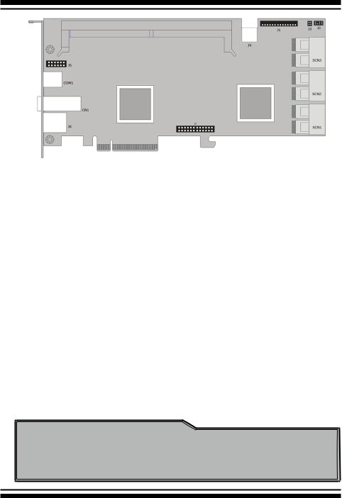
Figure 2-1, ARC-1883ix-12/16/24 Top View
Connector |
Type |
Description |
|
|
|
|
|
1. |
(J1) |
Flash-based/Battery Backup Module Connector |
14-pin box header |
|
|
|
|
2. |
(J2) |
I2C/LCD Connector |
7-pin header |
3. |
(J3) |
Global Fault/Activity LED |
4-pin header |
4. |
(J4) |
PCI-E Power Connector |
6-pin header |
5. |
(J5) |
Manufacture Purpose Port |
12-pin header |
|
|
|
|
6. |
(J6) |
Ethernet Port |
RJ45 |
|
|
|
|
7. |
(J7) |
Individaul Fault LED Header |
24-pin header |
|
|
|
|
8. |
(COM1) |
RS232 Port for CLI to configure the expander |
RJ11 connector |
|
|
functions on the RAID controller (*1) |
|
9. |
(CN1) |
Mini SAS HD 25-28 Ports (External) |
SFF-8644 |
|
|
|
|
10. (SCN1) |
Mini SAS HD 1-8 Ports (Internal) |
SFF-8643 |
|
11. (SCN2) |
Mini SAS HD 9-16 Ports (Internal) |
SFF-8643 |
|
|
|
|
|
12. (SCN3) |
Mini SAS HD 17-24 Ports (Internal) |
SFF-8643 |
|
|
|
|
|
Table 2-1, ARC-1883ix-12/16/24 Connectors
Note:
You can download the ARC1882ix_1883ix Expander-CLI.PDF manual from “http://www.areca.com.tw/support/main.htm” to view and set expander configuration.
17
HARDWARE INSTALLATION
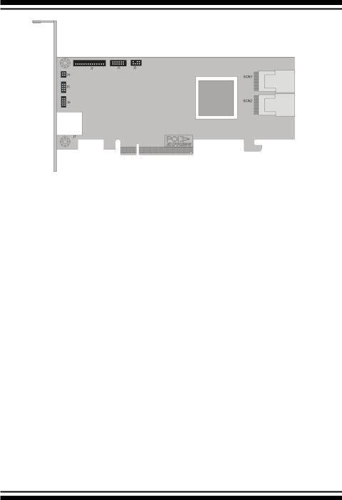
Figure 2-2, ARC-1883i Top View
Connector |
Type |
Description |
|
|
|
|
|
1. |
(J1) |
Manufacture Purpose Port |
12-pin header |
|
|
|
|
2. |
(J2) |
Flash-based/Battery Backup Module Connector |
14-pin box header |
|
|
|
|
3. |
(J3) |
I2C/LCD Connector |
7-pin header |
4. |
(J4) |
Global Fault/Activity LED |
4-pin header |
|
|
|
|
5. |
(J5) |
Individual Activity (HDD) LED Header |
4-pin header |
|
|
|
|
6. |
(J6) |
Individual Fault LED Header |
4-pin header |
|
|
|
|
7. |
(J7) |
Ethernet Port |
RJ45 |
|
|
|
|
8. |
(SCN1) |
Mini SAS HD 1-4 Ports (Internal) |
SFF-8643 |
|
|
|
|
9. |
(SCN2) |
Mini SAS HD 5-8 Ports (Internal) |
SFF-8643 |
|
|
|
|
Table 2-2, ARC-1883i Connectors
18

HARDWARE INSTALLATION
Figure 2-3, ARC-1883LP Top View
Connector |
|
Type |
Description |
|
|
|
|
|
|
1. |
(J1) |
Manufacture Purpose Port |
12-pin box header |
|
|
|
|
|
|
2. |
(J2) |
Flash-based/Battery Backup Module Connector |
14-pin header |
|
|
|
|
|
|
3. |
(J3) |
Global Fault/Activity LED |
4-pin header |
|
|
|
|
|
|
4. |
(J4) |
Individual Fault/Activity LED Header |
8-pin header |
|
|
|
|
|
|
5. |
(J5) |
I2C/LCD Connector |
7-pin header |
|
6. |
(SCN1) |
Mini SAS HD 5-8 |
Ports (External) |
SFF-8644 |
|
|
|
|
|
7. |
(SCN2) |
Mini SAS HD 1-4 |
Ports (Internal) |
SFF-8643 |
|
|
|
|
|
8. |
(J6) |
Ethernet Port |
|
RJ45 |
|
|
|
|
|
Table 2-3, ARC-1883LP Connectors
19
HARDWARE INSTALLATION
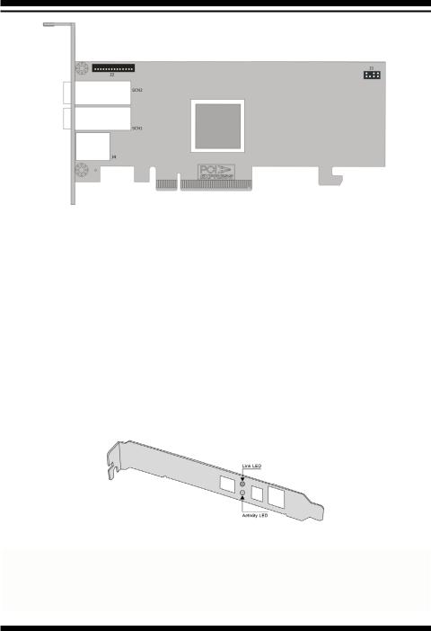
Figure 2-4, ARC-1883x Top View
Connector |
Type |
Description |
|
|
|
|
|
1. |
(J2) |
Flash-based/Battery Backup Module Connector |
14-pin box header |
|
|
|
|
2. |
(J3) |
I2C/LCD Connector |
7-pin header |
3. |
(J4) |
Ethernet Port |
RJ45 |
|
|
|
|
4. |
(SCN1) |
Mini SAS HD 5-8 Ports (External) |
SFF-8644 |
|
|
|
|
5. |
(SCN2) |
Mini SAS HD 1-4 Ports (External) |
SFF-8644 |
|
|
|
|
Table 2-4, ARC-1883x Connectors
The following table describes the ARC-1883ix external port Mini SAS HD SFF-8644 link/activity LED behavior.
LED |
Status |
|
|
Link LED |
When the link LED is lit that indicates the link LED is connected. |
(Green light) |
|
|
|
Activity LED |
The activity LED is lit that indicates the adapter is active. |
(Blue light) |
|
|
|
|
|
20
HARDWARE INSTALLATION
Tools Required
An ESD grounding strap or mat is required. Also required are standard hand tools to open your system’s case.
System Requirement
The 12Gb/s SAS RAID controller can be installed in an universal PCIe slot and requires a motherboard that:
ARC-1883 series 12Gb/s SAS RAID controller requires:
•Comply with the PCIe 3.0 x8 lanes
It can work on the PCIe 3.0 x1, x4, x8, and x16 signal with x8 or x16 mechanical slot M/B.
•Backward-compatibe with PCIe 1.0/2.0
Installation Tools
The following items may be needed to assist with installing the
12Gb/s SAS RAID controller into an available PCIe expansion slot.
•Small screwdriver
•Host system hardware manuals and manuals for the disk or enclosure being installed
Personal Safety Instructions
Use the following safety instructions to help you protect your computer system from potential damage and to ensure your own personal safety.
•Always wear a grounding strap or work on an ESD-protective mat.
•Before opening the system cover, turn off power switches and unplug the power cords. Do not reconnect the power cords until you have replaced the covers.
Electrostatic Discharge
Static electricity can cause serious damage to the electronic components on this 12Gb/s SAS RAID controller. To avoid damage
21

HARDWARE INSTALLATION
caused by electrostatic discharge, observe the following precautions:
•Do not remove the 12Gb/s SAS RAID controller from its antistatic packaging until you are ready to install it into a computer case.
•Handle the 12Gb/s SAS RAID controller by its edges or by the metal mounting brackets at its each end.
•Before you handle the 12Gb/s SAS RAID controller in any way, touch a grounded, anti-static surface, such as an unpainted portion of the system chassis, for a few seconds to discharge any built-up static electricity.
Warning:
High voltages may be found inside computer equipment. Before installing any of the hardware in this package or removing the protective covers of any computer equipment, turn off power switches and disconnect power cords. Do not reconnect the power cords until you have replaced the covers.
2.3 Installation
Use the instructions below to install a 12Gb/s SAS RAID controller.
Step 1. Unpack
Unpack and remove the 12Gb/s SAS RAID controller from the package. Inspect it carefully, if anything is missing or damaged, contact your local dealer.
Step 2. Power PC/Server Off
Turn off computer and remove the AC power cord. Remove the system’s cover. For the instructions, please see the computer system documentation.
Step 3. Check Memory Module (ARC-1883ix only)
Be sure of the cache memory module is present and seated firmly in the 240-pin DIMM socket for ARC1883ix-12/16/24 models. The
22
HARDWARE INSTALLATION
physical memory configuration for ARC-1883ix series is one 240pin DIMM socket for 2GB(default) up to 8GB DDR3-1866, 1Rx8, ECC module or 8GB, DDR3-1600, 2Rx8, ECC module.
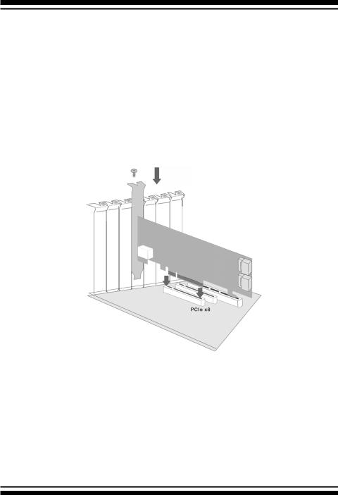
Step 4. Install the 12Gb/s SAS RAID Controllers
To install the 12Gb/s SAS RAID controller, remove the mounting screw and existing bracket from the rear panel behind the selected PCIe 3.0 slot. Align the gold-fingered edge on the card with the selected PCIe 3.0 slot. Press down gently but firmly to ensure that the card is properly seated in the slot, as shown in Figure 2-5.
Then, screw the bracket into the computer chassis. ARC-1883 series controllers require a PCIe 3.0 x8 slot for better performance.
Figure 2-5, Insert into a PCIe Slot
Step 5. Mount the Drives
You can connect the SAS/SATA drives to the controller through direct cable and backplane solutions. In the direct connection, SAS/ SATA drives are directly connected to 12Gb/s SAS RAID controller PHY port with SAS/SATA cables. The 12Gb/s SAS RAID controller can support up to 28 PHY ports. Remove the front bezel from the computer chassis and install the cages or SAS/SATA drives in the computer chassis. Loading drives to the drive tray if cages are
23

HARDWARE INSTALLATION
installed. Be sure that the power is connected to either the cage backplane or the individual drives.
In the backplane solution, SAS/SATA drives are directly connected to 12Gb/s SAS system backplane or through an expander board.
The number of SAS/SATA drives is limited to the number of slots available on the backplane. Some backplanes support daisy chain expansion to the next backplanes. The 12Gb/s SAS RAID controller can support daisy-chain up to 8 enclosures. The maximum drive no. is 256 devices through 8 enclosures. The following figure shows how to connect the external Mini SAS HD SFF-8644 cable from the 12Gb/s SAS RAID controller that has external connectors to the external drive boxes or drive enclosures.
Figure 2-6, Connecting to Drive Enclosure
The following table shows the maximum number of 12Gb/s SAS
RAID controller supported:
|
Disks/Enclosure |
Expander |
Disks/Controller |
Volume |
|
|
|
|
|
Max No. |
128 |
12 |
256 |
128 |
|
|
|
|
|
Note:
The maximum no. is 32 disk drives included in a single RAID set.
24

HARDWARE INSTALLATION
Step 6. Install SAS Cable
This section describes how to cable a controller to the drive or backplane.
Figure 2-7, Connecting to HDD
Figure 2-8, Connecting to Backplane
25

HARDWARE INSTALLATION
Step 7. Connect Power to the Controller (ARC-1883ix only)
There is a 6-pin PCI-E connector on the ARC-1883ix labelled J4.
You must plug in a PSU’s PCI-E cable at all times to supply enough stable power for the controller.
Figure 2-9, Connect Direct from Power Supply
If your power supply doesn’t have a 6 pin PCI-E power cable then you can use the adapter to convert two 4 pin peripheral power cables into a PCI-E power cable. If you use an adapter then be sure to plug the 4 pin peripheral power connectors into separate power cables coming from the power supply.
26

HARDWARE INSTALLATION
Figure 2-10, Connect through HDD/CD Cable
Step 8. Install the LED Cable (Optional)
The preferred I/O connector for server backplanes is the Mini SAS
HD SFF-8643 connector. This connector has eight signal pins to support four SAS/SATA drives and six pins for the SGPIO (Serial
General Purpose Input/Output) side-band signals. The SGPIO bus is used for efficient LED management and sensing drive locate status. See SFF 8485 for the specification of the SGPIO bus. For backplane without enclosure SGPIO support, please refer to section 2.5 LED cables for fault/activity LED cable installation.
LED Management: The backplane may contain LEDs to indicate drive status. Light from the LEDs could be transmitted to the outside of server by using light pipes mounted on the SAS drive tray. A small microcontroller on the backplane, connected via the SGPIO bus to a 12Gb/s SAS RAID controller, could control the LEDs. Activity: blinking 5 times/second and Fault: lit
27
HARDWARE INSTALLATION
Drive Locate: The location of a drive may be detected by sensing the voltage level of one of the pre-charge pins before and after a drive is installed.
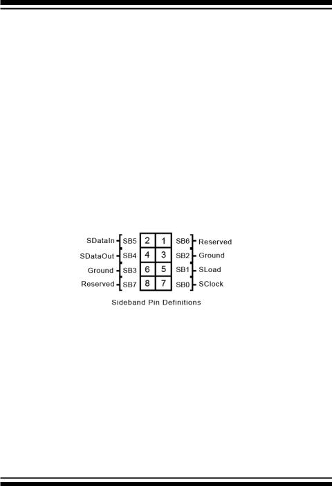
The following signals define the SGPIO assignments for the Mini SAS HD SFF-8643 in the 12Gb/s SAS RAID controller.
Pin |
Description |
Pin |
Description |
SideBand0 |
SClock (Clock signal) |
SideBand1 |
SLoad (Last clock of a bit |
|
|
|
stream) |
SideBand2 |
Ground |
SideBand3 |
Ground |
|
|
|
|
SideBand4 |
SDataOut (Serial data |
SideBand5 |
SDataIn (Serial data input bit |
|
output bit stream) |
|
stream) |
SideBand6 |
Reserved |
SideBand7 |
Reserved |
|
|
|
|
The Mini SAS HD SFF-8643 to 4xSATA with sideband cable follows the SFF-8448 specification. The SFF-8448 sideband signals cable is reserved for the backplane with header on it. The following signal defines the sideband connector which can work with Areca sideband cable on its Mini SAS HD SFF-8643 to 4xSATA cable.
The sideband header is located at backplane. For SGPIO to work properly, please connect the 8-pin sideband cable to the sideband header as shown above.
Step 9. Adding a FBM/BBM Backup Module (Optional)
Please refer to Appendix B and Appendix C of the user manual for installing the flash-based/battery backup module (FBM/BBM) in your 12Gb/s SAS RAID controller.
Step 10. Re-check Fault LED Cable Connections (Optional)
Be sure that the proper failed drive channel information is displayed by the fault LEDs. An improper connection will light the
28

HARDWARE INSTALLATION
wrong LED which causes the user to hot swap the wrong drive. This could result in failure and loss of system data.
Step 11. Power up the System
Thoroughly check the installation, reinstall the computer cover, and reconnect the power cord cables. Turn on the power switch at the rear of the computer (if equipped) and then press the power button at the front of the host computer.
Step 12. Install the Controller Driver
For a new system:
•Driver installation usually takes places as part of operating system installation. Please refer to Chapter 4 “Diver Installation” of the user manual for the detailed installation procedure.
In an existing system:
•To install the controller driver into the existing operating system.
For the detailed installation procedure, please refer to the Chapter 4 “Driver Installation” of the user manual.
Step 13. Install ArcHTTP Proxy Server
The 12Gb/s SAS RAID controller firmware has embedded the web-browser McRAID storage manager. ArcHTTP proxy server will launch the web-browser McRAID storage manager. It provides all of the creation, management and monitor 12Gb/s SAS RAID controller status. Please refer to the Chapter 5 of the user manual for the detail ArcHTTP Proxy Server Installation. For SNMP agent function, please refer to Appendix D of the user manual.
Step 14. Configure Volume Set
The controller configures RAID functionality through the McBIOS
RAID manager. Please refer to Chapter 3 of the user manual, McBIOS RAID Manager, for the detail. The RAID controller can also be configured through the McRAID storage manager with ArcHTTP proxy server installed or through on-board LAN port and LCD module (refer to LCD manual). For McRAID storage manager option, please refer to Chapter 6 of the user manual, Web Browser-Based
Configuration.
29

HARDWARE INSTALLATION
Step 15. Determining the Boot Sequences
For PC system:
12Gb/s SAS RAID controller is a bootable controller. If your system already contains a bootable device with an installed operating system, you can set up your system to boot a second operating system from the new controller. To add a second bootable controller, you may need to enter setup of motherboard BIOS and change the device boot sequence so that the new RAID controller heads the list. If the system BIOS setup does not allow this change, your system may be not configurable to allow the 12Gb/s SAS RAID controller to act as a second boot device.
For Intel-based Mac system:
Areca controller has supported the EFI BIOS on the PCIe 3.0 12Gb/s SAS RAID controller. You have other alternatively to add volumes on the Intel-based Mac bootable device listing. You can follow the following procedures to add 12Gb/s SAS RAID controller on the Mac bootable device listing.
1.Set the BIOS selection in System Controls: Advance Configuration to “EFI” option for Intel-based MacPro boot.
2.Download OS X Mavericks and DiskMaker X. Follow the DiskMaker X to make a bootable OS X Mavericks USB install drive.
3.Restart your Mac and after you hear the chime sound, press the Option (Alt) key until you see the option to choose the flash drive to boot from.
4.Follow the on-screen prompts to complete Areca Volume Upgrade and Clean Install of OS X Mavericks. Power up the Intel-based Mac and Areca volume will be added in the bootable device automatically.
30
Loading...