

Areca ARC-1203-4i operation manual

6Gb/s SATA RAID Cards
ARC-1203 series
(PCIe 2.0 to 6Gb/s SATA RAID Controllers)
User Manual
Version: 1.1
Issue Date: April, 2019

Copyright and Trademarks
The information regarding products in this manual is subject to change
without prior notice and does not represent a commitment on the part
of the vendor, who assumes no liability or responsibility for any errors
that may appear in this manual. All brands and trademarks are the
properties of their respective owners. This manual contains materials
protected under International Copyright Conventions. All rights
reserved. No part of this manual may be reproduced in any form or by
any means, electronic or mechanical, including photocopying, without
the written permission of the manufacturer and the author.
FCC Statement
This equipment has been tested and found to comply with the limits for a Class B digital device, pursuant to part 15 of the FCC Rules.
These limits are designed to provide reasonable protection against interference in a residential installation. This equipment generates, uses,
and can radiate radio frequency energy and, if not installed and used
in accordance with the instructions, may cause harmful interference to
radio communications. However, there is no guarantee that interference will not occur in a particular installation.
Manufacturer’s Declaration for CE Certication
We conrm ARC-1203 series has been tested and found compliant with
the requirements in the council directive relating to the EMC Directive
2004/108/EC. Regarding to the electromagnetic compatibility, the following standards were applied:
EN 55022: 2006, Class B
EN 61000-3-2: 2006
EN 61000-3-3: 1995+A1: 2001+A2: 2005
EN 55024:1998+A1:2001=A2:2003
IEC61000-4-2: 2001
IEC61000-4-3: 2006
IEC61000-4-4: 2004
IEC61000-4-5: 2005
IEC61000-4-6: 2006
IEC61000-4-8: 2001
IEC61000-4-11: 2004

Contents
1. Introduction .............................................................. 10
1.1 Overview ....................................................................... 10
1.2 Features ........................................................................ 12
2. Hardware Installation ............................................... 15
2.1 Before You First Installing................................................. 15
2.2 Board Layout .................................................................. 16
2.3 Installation ..................................................................... 17
2.4 SATA Cables ...................................................................23
2.4.1 Internal Min SAS 4i to SATA Cable ...............................23
2.4.2 Internal Min SAS 4i (SFF-8087) to Internal Min SAS 4i (SFF-
8087) cable ....................................................................... 24
2.5 LED Cables ..................................................................... 25
2.6 Summary of the installation .............................................. 29
3. McBIOS RAID Manager .............................................. 32
3.1 Starting the McBIOS RAID Manager ................................... 32
3.2 McBIOS RAID manager .................................................... 33
3.3 Conguring Raid Sets and Volume Sets .............................. 34
3.4 Designating Drives as Hot Spares ...................................... 34
3.5 Using Quick Volume /Raid Setup Conguration .................... 35
3.6 Using Raid Set/Volume Set Function Method ....................... 36
3.7 Main Menu .................................................................... 38
3.7.1 Quick Volume/Raid Setup ............................................ 39
3.7.2 Raid Set Function ....................................................... 43
3.7.2.1 Create Raid Set .................................................... 44
3.7.2.2 Delete Raid Set ..................................................... 45
3.7.2.3 Expand Raid Set .................................................... 46
3.7.2.4 Ofine Raid Set ..................................................... 47
3.7.2.5 Activate Incomplete Raid Set ...................................48
3.7.2.6 Create Hot Spare ................................................... 49
3.7.2.7 Delete Hot Spare ................................................... 49
3.7.2.8 Rescue Raid Set ...................................................50
3.7.2.9 Raid Set Information .............................................. 51
3.7.3 Volume Set Function ................................................... 51
• Volume Name ................................................................ 54
• Raid Level ..................................................................... 55
• Capacity ....................................................................... 55
• Stripe Size .................................................................... 57
• SCSI ID ........................................................................ 58

• SCSI LUN ...................................................................... 58
• Cache Mode .................................................................. 59
• Write Protect ................................................................. 59
• Tag Queuing .................................................................. 60
3.7.3.2 Create Raid30/50/60 (Volume Set 30/50/60) ............ 60
3.7.3.3 Delete Volume Set .................................................61
3.7.3.4 Modify Volume Set ................................................. 62
3.7.3.4.1 Volume Growth ................................................. 62
3.7.3.4.2 Volume Set Migration ........................................ 63
3.7.3.5 Check Volume Set ..................................................64
3.7.3.6 Stop Volume Set Check ..........................................64
3.7.3.7 Display Volume Set Info. ........................................ 64
3.7.4 Physical Drives ........................................................... 65
3.7.4.1 View Drive Information .......................................... 65
3.7.4.2 Create Pass-Through Disk ....................................... 66
3.7.4.3 Modify Pass-Through Disk ....................................... 67
3.7.4.4 Delete Pass-Through Disk ....................................... 67
3.7.4.5 Set Disk To Be Failed .............................................. 68
3.7.4.6 Activate Failed Disk ................................................ 68
3.7.4.7 Identify Selected Drive ........................................... 69
3.7.4.8 Identify Enclosure .................................................. 69
3.7.5 Raid System Function .................................................70
3.7.5.1 Mute The Alert Beeper ............................................ 70
3.7.5.2 Alert Beeper Setting ............................................... 71
3.7.5.3 Change Password .................................................. 71
3.7.5.4 JBOD/RAID Function .............................................. 72
3.7.5.5 Background Task Priority ........................................ 72
3.7.5.6 Maximum SATA Mode ............................................. 73
3.7.5.7 HDD Read Ahead Cache .......................................... 74
3.7.5.8 Volume Data Read Ahead ........................................ 74
3.7.5.9 Empty HDD Slot LED .............................................. 75
3.7.5.10 Auto Activate Raid Set .......................................... 76
3.7.5.11 Disk Write Cache Mode ......................................... 76
3.7.5.12 Write Same Support ............................................. 77
3.7.5.13 Capacity Truncation .............................................. 77
3.7.6 More System Functions ............................................... 78
3.7.6.1 Smart Option For HDD............................................ 79
3.7.6.2 Smart Polling Interval.............................................79
3.7.6.3 Hot Plugged Disk For Rebuilding ..............................80
3.7.7 HDD Power Management ............................................. 81
3.7.7.1 Stagger Power On .................................................. 82
3.7.7.2 Time To Hdd Low Power Idle ................................... 83

3.7.7.3 Time To Low RPM Mode ......................................... 83
3.7.7.4 Time To Spin Down Idle Hdd .................................. 84
3.7.8 Ethernet Conguration ............................................... 84
3.7.8.1 DHCP Function ...................................................... 84
3.7.8.2 Local IP address .................................................... 85
3.7.8.3 HTTP Port Number ................................................. 86
3.7.8.4 Telnet Port Number ................................................ 86
3.7.8.5 SMTP Port Number ................................................. 87
3.7.8.6 Ethernet Address ................................................... 88
3.7.9 Alert By Mail Cong ................................................... 88
3.7.10 View System Events .................................................. 89
3.7.11 Clear Events Buffer ................................................... 89
3.7.12 Hardware Monitor ..................................................... 90
3.7.13 System Information .................................................. 90
4. Driver Installation ..................................................... 91
4.1 Creating the Driver Diskettes ............................................ 91
4.2 Driver Installation for Windows ......................................... 92
4.2.1 Installing Windows on a RAID Volume ...........................92
4.2.2 Installing Controller on an Existing Windows .................. 94
4.2.3 Uninstall controller from Windows ................................. 95
4.3 Driver Installation for Linux .............................................. 96
4.4 Driver Installation for FreeBSD .......................................... 96
4.5 Driver Installation for Solaris ............................................ 97
4.6 Driver Installation for Mac X ............................................. 97
4.6.1 Installation Procedures ................................................ 98
4.6.2 Making Volume Sets Available to Mac OS X .................. 100
5. ArcHTTP Proxy Server Installation .......................... 102
5.1 For Windows................................................................. 103
5.2 For Linux ..................................................................... 108
5.3 For FreeBSD ................................................................. 110
5.4 For Solaris 10 ............................................................... 110
5.5 For Mac OS X ................................................................ 110
5.6 ArcHTTP Conguration ................................................... 111
6. Web Browser-based Conguration ......................... 116
6.1 Start-up McRAID Storage Manager ................................. 116
• Start-up from Windows/Mac Local Administration ............... 117
• Start-up McRAID Storage Manager from Linux/
FreeBSD/Solaris Local Administration ............................... 117
• Start-up from Ethernet Port (Out-of-Band) ....................... 118
6.2 McRAID Storage Manager ............................................... 119
6.3 Main Menu .................................................................. 120

6.4 Quick Function .............................................................. 120
6.5 Raid Set Functions ........................................................ 121
6.5.1 Create Raid Set ....................................................... 121
6.5.2 Delete Raid Set ........................................................ 122
6.5.3 Expand Raid Set ....................................................... 122
6.5.4 Ofine Raid Set ........................................................ 123
6.5.5 Rename Raid Set ...................................................... 124
6.5.6 Activate Incomplete Raid Set ..................................... 124
6.5.7 Create Hot Spare ..................................................... 125
6.5.8 Delete Hot Spare ...................................................... 126
6.5.9 Rescue Raid Set ....................................................... 126
6.6 Volume Set Functions .................................................... 127
6.6.1 Create Volume Set (0/1/10/3/5/6) ............................. 127
6.6.2 Create Raid 30/50/60 (Volume Set 30/50/60) .............. 130
6.6.3 Delete Volume Set .................................................... 131
6.6.4 Modify Volume Set .................................................... 132
6.6.4.1 Volume Growth ................................................... 132
6.6.4.2 Volume Set Migration ........................................... 133
6.6.5 Check Volume Set .................................................... 134
6.6.6 Schedule Volume Check ............................................ 134
6.6.7 Stop Volume Set Check ............................................. 135
6.7 Security Function .......................................................... 136
6.7.1 Create SED RAID Set ............................................... 136
6.7.2 Delete SED RAID Set ............................................... 137
6.7.3 Delete ISE RAID Set ................................................ 137
6.7.4 Security Key Setup ................................................... 138
6.7.4.1 SED Key Management-Creation ............................. 138
6.7.4.2 SED Key Management-Modication ........................ 139
6.7.5 Import Security Key .................................................. 140
6.7.6 Erase Failed Disk ...................................................... 141
6.7.7 RevertSP ................................................................. 141
6.8 Physical Drive .............................................................. 142
6.8.1 Create Pass-Through Disk .......................................... 142
6.8.2 Modify Pass-Through Disk .......................................... 142
6.8.3 Delete Pass-Through Disk .......................................... 143
6.8.4 Clone Disk ............................................................... 143
6.8.4.1 Clone And Replace ............................................... 144
6.8.4.2 Clone Only ......................................................... 145
6.8.5 Abort Cloning ........................................................... 145
6.8.6 Set Disk To Be Failed ................................................ 145
6.8.7 Activate Failed Disk .................................................. 145
6.8.8 Identify Enclosure .................................................... 146

6.8.9 Identify Drive .......................................................... 146
6.9 System Controls ........................................................... 147
6.9.1 System Cong ......................................................... 147
• System Beeper Setting ................................................. 147
• JBOD/RAID Conguration .............................................. 147
• Max SATA Mode Supported ............................................ 148
• HDD Read Ahead Cache ................................................ 148
• Volume Data Read Ahead ............................................. 148
• Empty HDD Slot LED .................................................... 148
• Max Command Length .................................................. 149
• Auto Activate Incomplete Raid ....................................... 149
• Disk Write Cache Mode ................................................. 149
• Write Same For Initialization .......................................... 149
• Hot Plugged Disk For Rebuilding ..................................... 149
• Disk Capacity Truncation Mode ....................................... 150
• Smart Option For HDD .................................................. 150
• Smart Polling Interval ................................................... 151
6.9.2 Advanced Conguration ............................................. 151
• TLER Setting ............................................................... 152
• Timeout Setting ........................................................... 152
• Number of Retries ........................................................ 152
• Buffer Threshold .......................................................... 152
• Amount of Read Ahead ................................................. 153
• Read Ahead Count ........................................................ 153
• Read Ahead Requests ................................................... 153
• Number of AV Stream ................................................... 153
• Optimize AV Recording .................................................. 154
• Read Performance Margin .............................................. 154
• Write Performance Margin ............................................. 154
• Read And Discard Parity Data ........................................ 155
• BIOS Selection............................................................. 155
6.9.3 HDD Power Management ........................................... 156
• Stagger Power On Control ............................................. 156
• Time To Hdd Low Power Idle ......................................... 157
• Time To Spin Down Idle HDD ......................................... 157
• SATA Power Up In Standby ........................................... 157
6.9.4 Ethernet Conguration ............................................. 157
• DHCP Function ............................................................. 158
• Local IP address ........................................................... 158
• Gateway IP address ...................................................... 159
• Subnet Mask ............................................................... 159
• HTTP Port Number ........................................................ 159

• Telnet Port Number ...................................................... 159
• SMTP Port Number ....................................................... 159
6.9.5 Alert By Mail Conguration ....................................... 159
6.9.6 SNMP Conguration .................................................. 160
6.9.7 NTP Conguration .................................................... 160
• NTP Sever Address ....................................................... 161
• Time Zone ................................................................... 161
• Automatic Daylight Saving............................................. 161
6.9.8 View Events/Mute Beeper .......................................... 162
6.9.9 Generate Test Event ................................................. 162
6.9.10 Clear Events Buffer ................................................. 163
6.9.11 Modify Password ..................................................... 163
6.9.12 Update Firmware ................................................... 164
6.10 Information ................................................................ 165
6.10.1 Raid Set Hierarchy .................................................. 165
6.10.2 System Information ................................................ 165
6.10.3 Hardware Monitor ................................................... 166
Appendix A ................................................................. 167
Upgrading Flash ROM Update Process .................................... 167
A-1 Overview ................................................................... 167
A-2 Upgrading Firmware Through McRAID Storage Manager ... 168
A-3 Upgrading Firmware Through nash DOS Utility .............. 169
A-4 Upgrading Firmware Through CLI .................................. 170
Appendix B .................................................................. 171
Battery Backup Module (ARC-6120BA-T121-12G) .................... 171
Appendix C .................................................................. 175
SNMP Operation & Installation .............................................. 175
C-1 Overview ................................................................... 175
C-2 SNMP Denition .......................................................... 175
C-3 SNMP Installation ....................................................... 176
C-3-1 Using ArcHTTP ....................................................... 178
C-3-2 Using Onboard NIC Installation ................................ 178
C-3-3 Using In-band PCIe + SNMP extension agent Installation
.................................................................................... 180
C-3-4 SNMP Extension Agent Installation .......................... 181
C-3-4-1 Windows .......................................................... 181
C-3-4-2 Linux .............................................................. 184
C-3-4-3 FreeBSD .......................................................... 185
Appendix D .................................................................. 186
Appendix E .................................................................. 190
Self-Encrypting Disk (SED) Encryption ................................. 190

Appendix F .................................................................. 196
RAID Concept .................................................................... 196
RAID Set ......................................................................... 196
Volume Set ...................................................................... 196
Ease of Use Features ......................................................... 197
• Foreground Availability/Background Initialization .............. 197
• Online Array Roaming ................................................... 197
• Online Capacity Expansion ............................................. 197
• Online RAID Level and Stripe Size Migration .................... 199
• Online Volume Expansion .............................................. 200
High Availability ............................................................... 200
• Global/Local Hot Spares ................................................ 200
• Hot-Swap Disk Drive Support ......................................... 201
• Auto Declare Hot-Spare ............................................... 201
• Auto Rebuilding ........................................................... 202
• Adjustable Rebuild Priority ............................................. 202
High Reliability ................................................................. 203
• Hard Drive Failure Prediction .......................................... 203
• Auto Reassign Sector .................................................... 203
• Consistency Check ....................................................... 204
Data Protection ................................................................ 205
• Battery Backup ........................................................... 205
• Recovery ROM ............................................................. 205
Appendix G .................................................................. 206
Understanding RAID .......................................................... 206
RAID 0 ............................................................................ 206
RAID 1 ............................................................................ 207
RAID 10(1E) .................................................................... 208
RAID 3 ............................................................................ 208
RAID 5 ............................................................................ 209
RAID 6 ............................................................................ 210
RAID x0 .......................................................................... 210
JBOD .............................................................................. 211
Single Disk (Pass-Through Disk) ......................................... 211
Summary of RAID Levels ................................................... 212

INTRODUCTION
1. Introduction
This section presents a brief overview of the 6Gb/s SATA RAID controller, ARC-1203-4i/8i. (PCIe 2.0 to 6Gb/s SATA RAID controllers)
1.1 Overview
The ARC-1203-4i/8i internal PCIe 2.0 host RAID controllers are a
cost-effective solutions for connecting up to 4/8 6Gb/s SATA peripheral devices. The RAID controllers are based on the same RAID
kernel of eld-proven internal/external RAID controller and same
device driver architecture with widely used 3Gb/s and 6Gb/s SAS/
SATA RAID controller. Applications that benet most features from
these controllers include NAS, server RAID solutions, web servers,
near-line backup, security systems and streaming applications.
ARC-1203 series support directly attached 4/8 internal 6Gb/s SATA
ports via 1/2 SFF-8087 connector.
The ARC-1203 series 6Gb/s RAID controllers are low-prole PCI
cards, ideal for 1U and 2U rack-mount systems. These controllers
utilize the same RAID kernel that has been eld-proven in existing
external RAID controller products, allowing Areca to quickly bring
stable and reliable PCIe 2.0 6Gb/s SATA RAID controllers to the
market.
Unparalleled Flexibility
Embedded with ARM-based storage I/O processor makes those
products a pure hardware RAID controller and raise the standard
to higher performance levels with several enhancements including
6Gb/s SATA ports, on-board 1GB SDRAM memory and high per-
formance PCIe 2.0 x8 lane host interface bus interconnection. The
ARC-1203 series RAID card with a dedicated processor and cache
memory that ofoads the parity calculations from the CPU, as this
means you can pair it with a slow, lower power processor, the cost
to benet ratio for this cost-effective RAID adapter is negligible.
With several port conguration options 4 internal and 8 internal
ARC-1203 series RAID can be easily integrated into a variety of
hardware and software platforms, and are ideal for cost-effective,
high-capacity NAS, DVR and cold storage market.
10

INTRODUCTION
Unsurpassed Data Availability
As storage capacities continue to rapidly increase, users need
greater level of disk drive fault tolerance, which can be implemented without doubling the investment in disk drives. The RAID
6 can offer fault tolerance greater that RAID 1 or RAID 5 but only
consumes the capacity of 2 disk drives for distributed parity data.
Areca entry-level RAID controllers incorporate onboard storage processors to deliver true hardware RAID. Hardware RAID cards have
their own local RAID processor onboard, plus dedicated onboard
cache for full hardware ofoading of RAID-processing functions.
The ability of hardware RAID controllers to rebuild an array in the
event of a drive failure is superior to what software RAID controllers offer.
The ARC-1203 series 6Gb/s SATA RAID controllers can also provide
RAID levels 0, 1, 1E, 3, 5, 6, 10, 30, 50, 60, Single Disk or JBOD
for maximum conguration exibility. Its high data availability and
protection derives from Areca Technology’s advanced features: On-
line RAID Capacity Expansion, Array Roaming, Online RAID Level /
Stripe Size Migration, Global Online Spare, Automatic Drive Failure
Detection, Automatic Failed Drive Rebuilding, Disk Hot-Swap, Online Background Rebuilding, Instant Availability/Background Initialization, Auto Reassign Sector, Redundant Flash Image and Battery Backup Module. The optional battery backup module provides
power to the cache if it contains data not yet written to the drives
when power is lost.
Maximum Interoperability
The ARC-1203 series 6Gb/s SATA RAID adapters support broad
operating system including Windows 10/8/server 2012/2008/Vis-
ta/2003/XP(64-bit), Linux (Open Source), FreeBSD (Open Source),
VMware, Solaris (Open Source), Mac and more, along with key
system monitoring features such as enclosure management (Serial
bus & SGPIO) and SNMP function. Our products and technology are
based on extensive testing and validation process; same as Areca
3Gb/s and 6Gb/s SAS/SATA RAID adapter eld-proven compatibil-
ity with operating systems, motherboards, applications and device
drives.
11

INTRODUCTION
Easy RAID Management
The controllers contain an embedded McBIOS RAID manager that
can access via hot key at M/B BIOS boot-up screen. This pre-boot
McBIOS RAID manager can use to simplify the setup and manage-
ment of RAID controller. The controller rmware also contains a
browser-based McRAID storage manager which can be accessed
through the Ethernet port or ArcHttp proxy server in Windows,
Linux, FreeBSD and more environments. The McRAID storage man-
ager allows local and remote to create and modify RAID set, volume set, and monitor RAID status from standard web browser. The
ArcSAP quick manager can scan for multiple RAID units in the local
and remote systems and provide an effective mechanism to congure and monitor your RAID units.
1.2 Features
Controller Architecture
• ARM_based 1066MHz storage I/O processor
• 1GB on-board DDR3-1066 SDRAM with ECC protection
• PCIe 2.0 x4 lanes host interface
• Support up to 4/8 x 6Gb/s SATA HDDs/SSD
• Multi-adapter support for large storage requirements
• BIOS boot support for greater fault tolerance
• BIOS PnP (plug and play) and BBS (BIOS boot specication)
support
• Boot support for the uEFI host BIOS
• NVRAM for RAID event & transaction log
• Redundant ash image for controller availability
• Battery Backup Module (BBM) ready (optional)
• RoHS compliant
RAID Features
• RAID level 0, 1, 10(1E), 3, 5, 6, 30, 50, 60, Single Disk or JBOD
• Multi-level RAID 0 and RAID 10 (R00 and R100)
• Support up to 1MB stripe size
• Multiple RAID selection
• Online array roaming
• Online RAID level/stripe size migration
• Online capacity expansion and RAID level migration simultane-
ously
12

INTRODUCTION
• Online volume set growth
• Instant availability and background initialization
• Support global and dedicated hot spare
• Automatic drive insertion/removal detection and rebuilding
• Greater than 2TB capacity per disk drive support
• Greater than 2TB per volume set (64-bit LBA support)
• SED (self-encrypting drives) function support
• Support intelligent power management to save energy and ex-
tend service life
• Support for native 4K and 512 byte sector SATA devices
• Multiple pairs SSD/HDD disk clone function
• SSD automatic monitor clone (AMC) support
• Support HDD rmware update
Monitors/Notication
• System status indication through global HDD activity/fault con-
nector, individual fault connector, LCD/serial bus connector an d
alarm buzzer
• SMTP support for email notication
• SNMP support for remote manager
• Enclosure management (Serial bus & SGPIO) ready
RAID Management
• Field-upgradeable rmware in ash ROM
In-Band Manager
• Hot key "boot-up" McBIOS RAID manager via M/B BIOS
• Web browser-based McRAID storage manager via ArcHTTP proxy
server for all operating systems
• Support Command Line Interface (CLI)
• API library for customer to write manager utility
• Single Admin Portal (ArcSAP) quick manager utility
Out-of-Band Manager
• Firmware-embedded web browser-based McRAID storage manager, SMTP manager, SNMP agent and Telnet function via Ethernet port
• Out-of-Band API sample and functional code for customer to
quickly customize its AP
• Support push button and LCD display panel (optional)
13
INTRODUCTION
Operating System
• Windows 10/8/2012/7/2008/Vista/XP(64-bit)/2003
• Linux
• FreeBSD
• VMware (Driver 6.x support CLI in-band management utility)
• Solaris 10/11 x86/x86_64
• Mac OS 10.5.x or higher
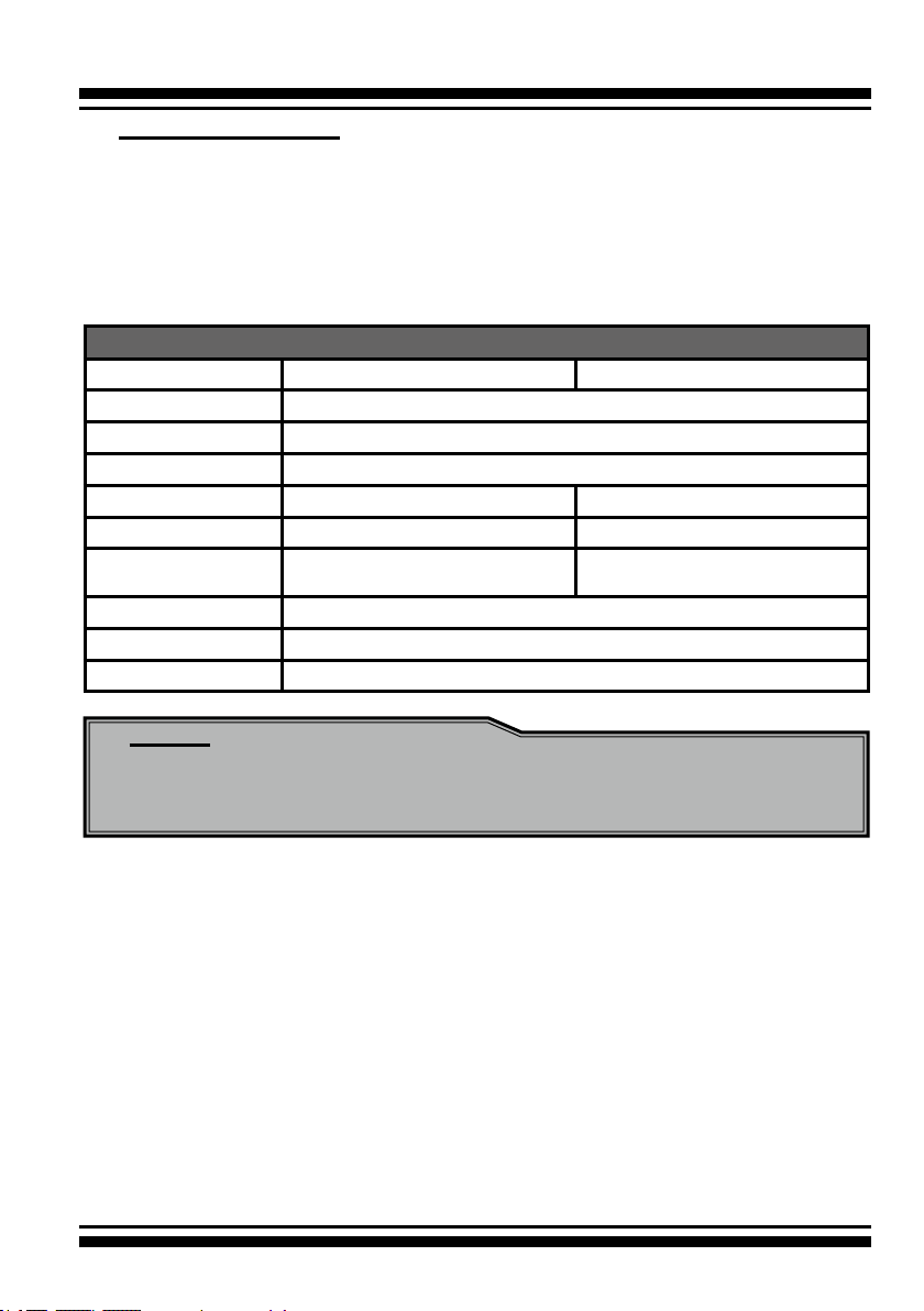
6Gb/s SATA RAID controllers
Model name ARC-1203-4i ARC-1203-8i
I/O Processor ARM_based 1066MHz storage I/O processor
Form Factor (H x L) Low Prole: 64.4 x 168 mm
Host Bus Type PCIe 2.0 x4 Lanes
Driver Connector 1xSFF-8087 2xSFF-8087
Drive Support Up to 4 x 6Gb/s SATA HDDs/SSD Up to 8 x 6Gb/s SATA HDDs/SSD
RAID Level 0, 1, 1E, 3, 5, 6, Single Disk, and
JBOD
On-Board Cache 1GB on-board DDR3-1066 SDRAM with ECC protection
Management Port In-Band: PCIe / Out-of-Band: LCD, and LAN Port
Enclosure Ready Individual Faulty Header, SGPIO, and Serial bus
0, 1, 1E, 3, 5, 6, 10, 30, 50, 60,
Single Disk, and JBOD
Note:
Low-prole bracket has included on the low prole board shipping
package.
14

INTRODUCTION
2. Hardware Installation
This section describes the procedures for installing the 6Gb/s SATA RAID
controllers.
2.1 Before You First Installing
Thanks for purchasing the 6Gb/s SATA RAID controller as your
RAID data storage subsystem. This user manual gives simple step-
by-step instructions for installing and conguring the 6Gb/s SATA
RAID controller. To ensure personal safety and to protect your
equipment and data, reading the following information package list
carefully before you begin installing.
Package Contents
If your package is missing any of the items listed below, contact your local dealers before you install. (Disk drives and disk
mounting brackets are not included)
• 1 x 6Gb/s SATA RAID controller in an ESD-protective bag
• 1 x Installation CD – containing driver, relative software, an elec-
tronic version of this manual and other related manual
• 1 x Quick start guide
• 1 x Low-prole bracket
System Requirement
The 6Gb/s SATA RAID controller can be installed in an universal
PCIe slot and requires a motherboard that:
ARC-1203 series 6Gb/s SATA RAID controller requires:
• Comply with the PCIe 2.0 x4 lanes
It can work on the PCIe 2.0 x1, x4 and x8 signal with x4 or x8
slot M/B.
• Backward-compatibe with PCIe 1.0
15
HARDWARE INSTALLATION
2.2 Board Layout
The RAID controllers can support a family SATA interface included
4/8 internal ports with 6Gb/s capability. This section provides the
board layout and connector/jumper for the 6Gb/s SATA RAID controller.
Figure 2-1, ARC-1203-4i/8i 6Gb/s SATA RAID controller
Connector Type Description
1. (J1) Manufacture Purpose Port 14-pin header
2. (J2) Battery Backup Module Connector 14-pin box header
3. (J3) I2C/LCD Connector 7-pin header
4. (J4) Global Fault/Activity LED 4-pin header
5. (J5) Individual Activity LED (1-8 Ports) Header 8-pin header
6. (J6) Individual Fault LED (1-8 Ports) Header 8-pin header
7. (J7) Ethernet port RJ45
8. (SCN1) SATA 1-4 Ports SFF-8087
9. (SCN2) SATA 5-8 Ports (for ARC-1203-8i) SFF-8087
Table 2-1, ARC-1203-4i/8i connectors
16

HARDWARE INSTALLATION
2.3 Installation
Use the following instructions below to install a PCIe 2.0 6Gb/s
SATA RAID controller.
Step 1. Unpack
Unpack and remove the PCIe 2.0 6Gb/s SATA RAID controller from
the package. Inspect it carefully, if anything is missing or damaged,
contact your local dealer.
Step 2. Power PC/Server Off
Turn off computer and remove the AC power cord. Remove the system’s cover. For the instructions, please see the computer system
documentation.
Step 3. Install the PCIe 6Gb/s SATA RAID Cards
To install the 6Gb/s SATA RAID controller, remove the mounting
screw and existing bracket from the rear panel behind the selected
PCIe 2.0 slot. Align the gold-ngered edge on the card with the
selected PCIe 2.0 slot. Press down gently but rmly to ensure that
the card is properly seated in the slot, as shown on Figure 2-2.
Then, screw the bracket into the computer chassis. ARC-1203 series controllers require a PCIe 2.0 x4/x8 slot.
Figure 2-2, Insert into a
PCIe slot
17

HARDWARE INSTALLATION
Step 4. Mount the Drives
You can connect the SATA drives to the controller through direct
cable and backplane solutions. In the direct connection, SATA
drives are directly connected to 6Gb/s SATA RAID controller port
with SATA cables. The 6Gb/s SATA RAID controller can support up
to 8 ports. Remove the front bezel from the computer chassis and
install the cages or SATA drives in the computer chassis. Loading
drives to the drive tray if cages are installed. Be sure that the
power is connected to either the cage backplane or the individual
drives.
In the backplane solution, SATA drives are directly connected
to 6Gb/s SATA system backplane. The number of SATA drives is
limited to the number of slots available on the system backplane.
Step 5. Install SATA Cable
This section describes SATA cable how to connect on controller.
18
Figure 2-3, Connecting to HDD

HARDWARE INSTALLATION
Figure 2-4, Connecting to Backplane
Step 6. Install the LED Cable (Optional)
The preferred I/O connector for server backplanes is the internal
SFF-8087 connector. This connector has eight signal pins to sup-
port four SATA drives and six pins for the SGPIO (Serial General
Purpose Input/Output) side-band signals. The SGPIO bus is used
for efcient LED management and for sensing drive Locate status.
See SFF 8485 for the specication of the SGPIO bus. For backplane
without SGPIO supporting, Please refer to Section 2.6 LED cables
for fault/activity LED cable installation.
LED Management: The backplane may contain LEDs to indicate
drive status. Light from the LEDs could be transmitted to the outside of the server by using light pipes mounted on the SATA drive
tray. A small microcontroller on the backplane, connected via the
SGPIO bus to a 6Gb/s SATA RAID controller, could control the LEDs.
Activity: blinking 5 times/second and Fault: solid illuminated
Drive Locate Circuitry: The location of a drive may be detected by
sensing the voltage level of one of the pre-charge pins before and
after a drive is installed.
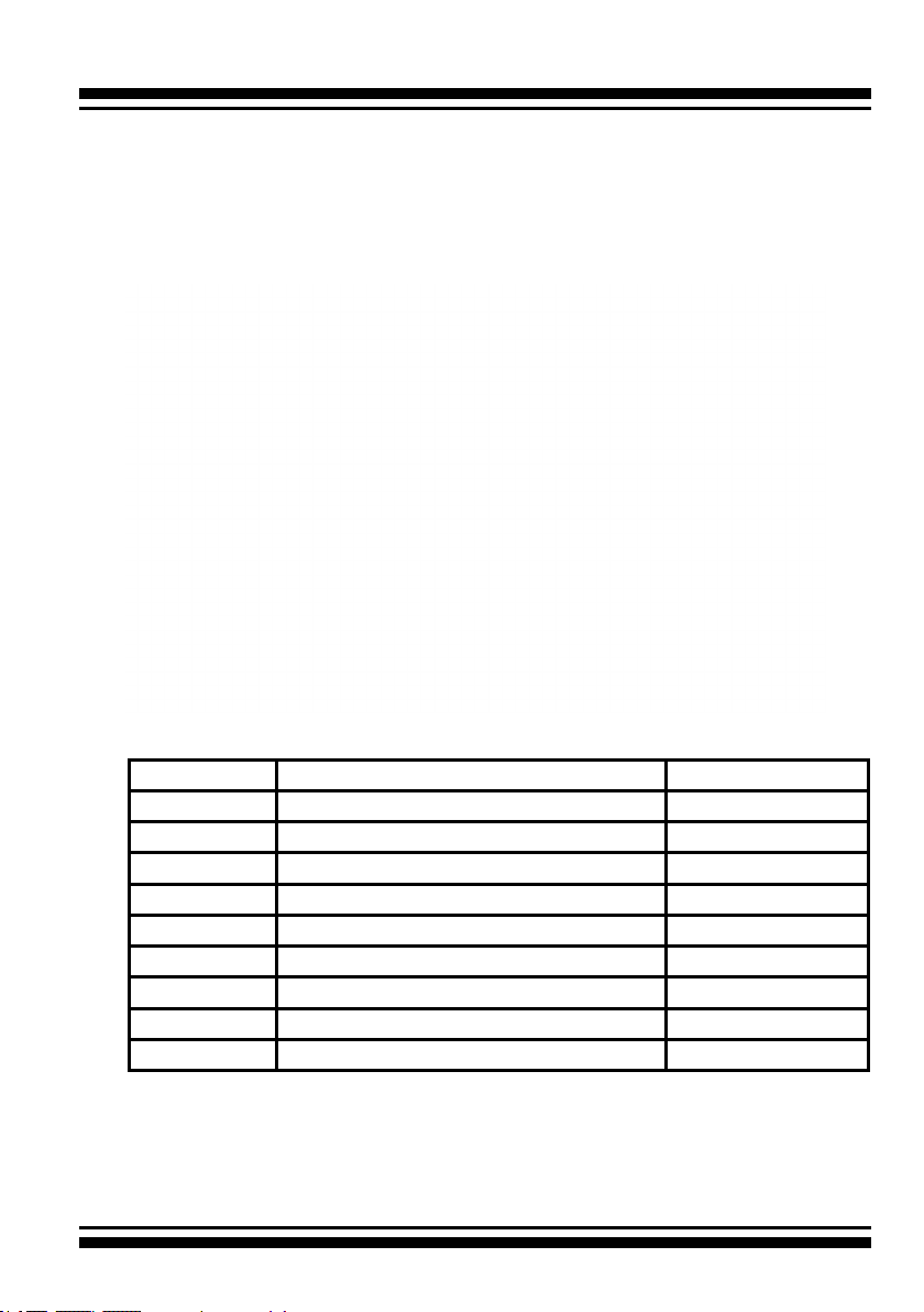
The following signals dene the SGPIO assignments for the Min
SAS 4i internal connector (SFF-8087) in the 6Gb/s SATA RAID controller.
19

HARDWARE INSTALLATION
PIN Description PIN Description
SideBand0 SClock (Clock signal) SideBand1 SLoad (Last clock of a bit stream)
SideBand2 Ground SideBand3 Ground
SideBand4 SDataOut (Serial data
output bit stream)
SideBand6 Reserved SideBand7 Reserved
Step 7. Adding a Battery Backup Module (Optional)
Please refer to Appendix B Battery Backup Module (ARC-6120BA-
T121) for installing the BBM in your 6Gb/s SATA RAID controller.
Step 8. Re-check Fault LED Cable Connections (Optional)
Be sure that the proper failed drive channel information is displayed by the fault LEDs. An improper connection will tell the user
to ‘‘Hot Swap’’ the wrong drive. This can result in removing the
wrong disk (one that is functioning properly) from the controller.
This can result in failure and loss of system data.
SideBand5 SDataIn (Serial data input bit
stream)
Step 9. Power up the System
Throughly check the installation, reinstall the computer cover, and
reconnect the power cord cables. Turn on the power switch at the
rear of the computer (if equipped) and then press the power button
at the front of the host computer.
Step 10. Install the Controller Driver
For a new system:
• Driver installation usually takes places as part of operating sys-
tem installation. Please refer to Chapter 4 “Diver Installation” for
the detailed installation procedure.
For an existing system:
• To install the controller driver into the existing operating system.
For the detailed installation procedure, please refer to the Chapter 4, “Driver Installation”.
20

HARDWARE INSTALLATION
Step 11. Install ArcHTTP Proxy Server
The ARC-1203 rmware has embedded the web-browser McRAID
storage manager. ArcHTTP proxy server will launch the web-
browser McRAID storage manager. It provides all of the creation,
management and monitor ARC-1203 series RAID controller status.
Please refer to the Chapter 5 for the detail “ArcHTTP Proxy Server
Installation”. For SNMP agent function, please see the “SNMP
Operation & Installation” section in the Appendix C of the user
manual.
Step 12. Congure Volume Set
With Areca series RAID cards, there are 4 methods to manage your
ARC-1203 series RAID controller. It can be congured by using the
LCD with keypad, McBIOS RAID manager (terminal emulation) or
McRAID storage manager (via LAN port and ArcHTTP proxy utility).
• Method 1: Internal PCIe Connection (McBIOS RAID Manager)
The ARC-1203 series RAID controller can be congured via a
BIOS start up McBIOS manager. The McBIOS RAID manager is
rmware-based and is used to congure RAID sets and volume
sets. Because the utility resides in the ARC-1203 series RAID
controller rmware, operation is independent of any operating
systems on your computer. For additional information on using
the BIOS on-screen to congure the RAID subsystem see the
Chapter 3 of “BIOS Conguration” of the user manual.
• Method 2: Internal PCIe Connection (McRAID Storage Manager)
You’re now ready to use the McRAID storage manager to set up
RAID volumes. Your ARC-1203 series RAID controller can be congured by using McRAID storage manager (launched by ArcHTTP
proxy server). ARC-1203 RAID controller has embedded the TCP/
IP & web browser-based RAID manager in the rmware. User can
use the standard web browsers to manage the RAID controller
using ArcHTTP proxy server installed. For additional information
on using the McRAID storage manager to congure the RAID controller see the Chapter 6 of “Web Browser-Based Conguration”
of the user manual.
• Method 3: LAN Port Connection (McRAID Storage Manager)
The ARC-1203 RAID controller has embedded the TCP/IP & web
21

HARDWARE INSTALLATION
browser-based RAID manager in the rmware. User can remote
manage the RAID controller without adding any user specic soft-
ware (platform independent) via standard web browsers directly
connected to the 10/100Mbits RJ45 LAN port. For additional information on using the LAN port to congure the RAID subsystem
see the Chapter 6 of “Web Browser-Based Conguration” of the
user manual.
• Method 4: Front LCD Panel with Keypad (Optional)
You can use LCD front panel and keypad function to simply create
the RAID volume. The LCD status panel also informs you of the
disk array’s current operating status at a glance. For additional
information on using the LCD to congure the RAID controller see
the ARC1000_LCD manual on the shipping CD. The LCD provides
a system of screens with areas for information, status indication,
or menus. The LCD screen displays up to two lines at a time of
menu items or other information.
Step 13. Format, Partition and Mount the ARC-1203 RAID
Controller Volumes
After the volume set is ready for system accesses, it needs to be
partitioned, formatted, and mounted by the operating system.
There are various steps, depending on what operating system you
are using (Windows, Linux, FreeBSD or Mac, etc.). Detailed steps
for each operating system are provided on their disk utility. After
that, the ARC-1203 series RAID controller can be fully used.
Step 14. Determining the Boot Sequences
The ARC-1203 series RAID controller is a bootable device. You can
use it as primary boot drive or secondary storage drive. If your
system already contains a bootable device with an installed operating system, you can set up your system to boot a second operating
system from the new ARC-1203 series RAID controller volume.
For PC system:
To add a second bootable controller, you may need to enter setup
of motherboard BIOS and change the device boot sequence so that
the new ARC-1203 series RAID controller volume heads the list. If
the system BIOS setup does not allow this change, your system
22

HARDWARE INSTALLATION
may be not congurable to allow the new ARC-1203 RAID controller volume to act as a second boot device.
For Apple Mac Pro system:
Areca controller has supported the uEFI BIOS on the PCIe 2.0
6Gb/s SATA RAID controller. You have other alternatively to add
volumes on the Intel-based Mac bootable device listing. You can
follow the following procedures to add 6Gb/s SATA RAID controller
on the Mac bootable device listing.
1. Set the BIOS selection in System Controls: Advance Congura-
tion to “uEFI” option for Intel_based MacPro boot.
2. Ghost (such as Carbon Copy Cloner ghost utility) the Mac OS X
system disk on the Intel-based Mac to the external 6Gb/s SATA
RAID controller volume set. Carbon Copy Cloner is an archival
type of back up software. You can take your whole Mac OS X
system and make a carbon copy or clone to Areca volume simi lar as an other hard drive.
3. Power up Intel-based Mac, it will take about 30 seconds for con-
troller rmware ready. Areca volume will be added in the
bootable device automatically.
2.4 SATA Cables
You can connect the end devices to each other through direct
cables or through the SATA backplane connections. The following is
an example of some internal SATA cables.
2.4.1 Internal Min SAS 4i to SATA Cable
The Min SAS 4i to SATA cables are used for connection between
the 6Gb/s SATA RAID controller internal connectors and connectors on the SATA disk drives or SAS/SATA connector backplane.
The 6Gb/s SATA controllers have 1-4 Min SAS 4i (SFF-8087)
internal connectors, each of them can support up to four SATA
drives.
These controllers can be installed in a server RAID enclosure with
standard SATA/SAS connectors backplane. The following diagram
23

HARDWARE INSTALLATION
shows the picture of Min SAS 4i to 4*SATA cables. Backplane
supports SGPIO header can leverage the SGPIO function on the
6Gb/s SATA RAID controller through the sideband cable.
Figure 2-5, SFF-8087 to 4x SATA cable
The SFF-8448 sideband signals cable is reserved for the backplane with header on it.
2.4.2 Internal Min SAS 4i (SFF-8087) to Internal Min SAS 4i (SFF-8087) cable
The 6Gb/s SATA RAID controllers have 1-4 Min SAS 4i internal
SFF-8087 connectors, each of them can support up to four SATA
signals. These controllers can be installed in a server RAID enclosure with Min SAS 4i internal connectors backplane. This Min SAS
4i cable has eight signal pins to support four SATA drives and six
pins for the SGPIO (Serial General Purpose Input/Output) sideband signals. The SGPIO bus is used for efcient LED management and for sensing drive Locate status.
Figure 2-6, SFF-8087 cable
24
HARDWARE INSTALLATION
2.5 LED Cables
There is no SGPIO supported in the most of old version SATA
backplane. The 6Gb/s SATA controller also provides two kinds of
alternative LED cable header to support the fault/activity status
for those backplanes. The global indicator connector is used by the
server/desktop system global indicator LED.
The following electronics schematic is the 6Gb/s SATA RAID controller logical of fault/activity header. The signal from EPLD CTL
output pin is cathode (-) side.
The following diagrams and descriptions describe each type of connector.
Note:
A cable for the global indicator comes with your computer
system. Cables for the individual drive LEDs may come with a
drive cage, or you may need to purchase them.
A: Individual Fault LED and Global Activity/Fault Indicator
Connector
Most of the backplanes have supported the HDD activity from
the HDD. The 6Gb/s SATA RAID controller also provides the fault
activity for fault LED. Connect the cables for the drive fault LEDs
between the backplane of the cage and the respective connector on
the 6Gb/s SATA RAID controller.
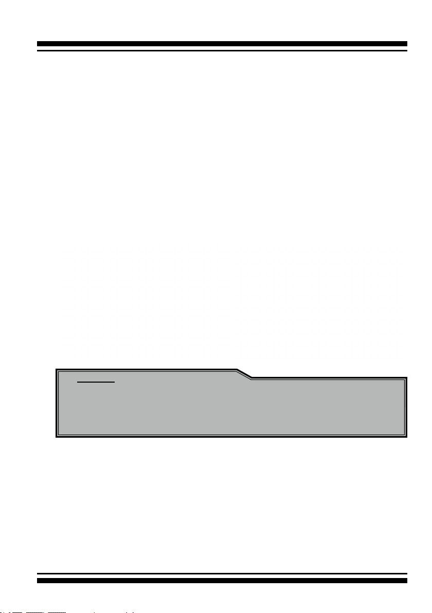
The following table is the fault LED signal behavior.
25

HARDWARE INSTALLATION
LED Normal Status Problem Indication
Fault LED 1. When the fault LED is
solid illuminated, there
is no disk present.
2. When the fault LED is
off, then disk is present
and status is normal.
If the system will use only a single global indicator, attach the LED
to the two pins of the global activity/fault connector. The global
fault pin pair connector is the overall fault signal. This signal will
light up in any disk drive failure.
1. When the fault LED is slow blinking (2
times/sec), that disk drive has failed
and should be hot-swapped immediately.
2. When the activity LED is illuminated
and fault LED is fast blinking (10 times/
sec) there is rebuilding activity on that
disk drive.
26
Figure 2-7, ARC-1203-4i/8i LED Indicator Connector
Figure 2-8, ARC-1203-12i/16i LED Indicator Connector
HARDWARE INSTALLATION
B: Areca Serial Bus Connector
The serial bus connector can add optional accessories to add
RAID controller more functions. You can connect this interface to
Areca LCD module for information, status indication, or menus
or Card LED indicator for status message. This interface can
also cascade to another Areca serial bus accessories for the
additional status display.
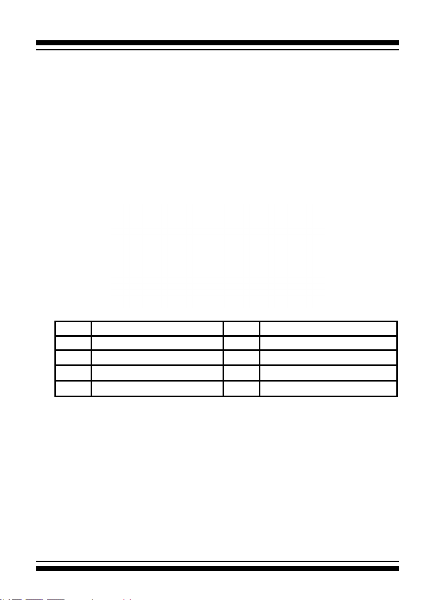
The following picture and table is the serial bus signal name description for the LCD/I2C Module Connector (J3).
PIN Description PIN Description
1 Power (+5V) 2 GND
3 LCD Module Interrupt 4 Protect Key
5 LCD Module Serial Data 6 Fault/Activity Clock
7 Fault/Activity Serial Data 8 LCD Module Clock
You can use one optional LCD front panel and keypad function to
simply create the RAID volume. The LCD status panel also informs
you the disk array’s current operating status at a glance. The LCD
conguration is described in a separate manual: RAID Card_LCD
manual. The LCD housed in a 5¼-inch half-height or 3.5-inch
canister.
27

HARDWARE INSTALLATION
Figure 2-9, Connect to LCD Status Panel
You can use one optional Card LED indicator connected serial bus
interface to display fault/activity status on I/O bracket or 3.5-inch
canister. This LED provides indications about the operational state
of the HDD on the RAID controller.
28
Figure 2-10, Connect to LED Indicator

HARDWARE INSTALLATION
2.6 Summary of the installation
The ow chart below describes the installation procedures for 6Gb/s
SATA RAID controllers.
These procedures includes hardware installation, the creation and
conguration of a RAID volume through the McBIOS/McRAID manager, OS installation and installation of 6Gb/s SATA RAID controller
software.
The software components congure and monitor the 6Gb/s SATA
RAID controllers as following table.
Conguration Utility Operating System Supported
McBIOS RAID Manager OS-Independent
McRAID Storage Manager
(Via ArcHTTP proxy server)
McRAID Storage Manager
(Via Ethernet port)
SAP Monitor (Single Admin Portal to
scan for multiple RAID units in the net-
work, via ArcHTTP proxy server)
SNMP Manager Console Integration Windows 10/8/2012/7/2008/Vista/
Windows 10/8/2012/7/2008/Vista/
XP(64-bit)/2003, Linux, FreeBSD, Solaris and Mac
OS-Independent
Windows 10/8/2012/7/2008/Vista/
XP(64-bit)/2003
XP(64-bit)/2003, Linux and FreeBSD
29

HARDWARE INSTALLATION
McRAID Storage Manager
Before launching the rmware-embedded web browser, McRAID
storage manager through the PCIe bus, you need rst to install the
ArcHTTP proxy server on your server system. If you need additional
information about installation and start-up of this function, see the
McRAID Storage Manager section in Chapter 6 of the user manual.
ArcHTTP Proxy Server
ArcHTTP has to be installed for GUI RAID console (MRAID storage
manager) to run. It is used to launch the web browser McRAID
storage manager. It also runs as a service or daemon in the background that allows capturing of events for mail and SNMP traps no-
tication. If you need additional information about installation and
start-up of this function, see the ArcHTTP Proxy Server Installation
section in Chapter 5 of the user manual.
CLI Utility
CLI (Command Line Interface) lets you set up and manage RAID
controller through a command line interface. CLI performs many
tasks at the command line. You can download CLI manual from
Areca website or software CD <CDROM>\DOCS directory.
SNMP Manager Console Integration
There are two ways to transport SNMP data on the ARC-1203 RAID
controller: in-band PCIe host bus interface or out-of-band builtin LAN interface. Enter the “SNMP Tarp IP Address” option on the
rmware-embedded SNMP conguration function for user to select
the SNMP data agent-side communication from the out-of-band
built-in LAN interface. To use in-band PCIe host bus interface, keep
blank on the “SNMP Tarp IP Address” options.
• Out of Band-Using LAN Port Interface
Out-of-band interface refers to transport SNMP data of 6Gb/s
SATA controllers from a remote station connected to the
controller through a network cable. Before launching the SNMP
manager on the clinet, you need rstly to enable the rmware-
embedded SNMP agent function and no additional agent
30
 Loading...