

Areca ARC-1203-2i operation manual

6Gb/s SATA RAID Cards
ARC-1203 - 2 ports
(PCIe 2.0 to 6Gb/s SATA RAID Controllers)
User Manual
Version: 1.1
Issue Date: April, 2019

Copyright and Trademarks
The information regarding products in this manual is subject to change
without prior notice and does not represent a commitment on the part
of the vendor, who assumes no liability or responsibility for any errors
that may appear in this manual. All brands and trademarks are the
properties of their respective owners. This manual contains materials
protected under International Copyright Conventions. All rights
reserved. No part of this manual may be reproduced in any form or by
any means, electronic or mechanical, including photocopying, without
the written permission of the manufacturer and the author.
FCC Statement
This equipment has been tested and found to comply with the limits for a Class B digital device, pursuant to part 15 of the FCC Rules.
These limits are designed to provide reasonable protection against interference in a residential installation. This equipment generates, uses,
and can radiate radio frequency energy and, if not installed and used
in accordance with the instructions, may cause harmful interference to
radio communications. However, there is no guarantee that interference will not occur in a particular installation.
Manufacturer’s Declaration for CE Certication
We conrm ARC-1203-2I has been tested and found compliant with
the requirements in the council directive relating to the EMC Directive
2004/108/EC. Regarding to the electromagnetic compatibility, the following standards were applied:
EN 55022: 2006, Class B
EN 61000-3-2: 2006
EN 61000-3-3: 1995+A1: 2001+A2: 2005
EN 55024:1998+A1:2001=A2:2003
IEC61000-4-2: 2001
IEC61000-4-3: 2006
IEC61000-4-4: 2004
IEC61000-4-5: 2005
IEC61000-4-6: 2006
IEC61000-4-8: 2001
IEC61000-4-11: 2004

Contents
1. Introduction .............................................................. 10
1.1 Overview ....................................................................... 10
1.2 Features ........................................................................ 12
2. Hardware Installation ............................................... 14
2.1 Before You First Installing................................................. 14
2.2 Board Layout .................................................................. 14
2.3 Installation ..................................................................... 18
2.4 Summary of the installation .............................................. 26
3. McBIOS RAID Manager .............................................. 29
3.1 Starting the McBIOS RAID Manager ................................... 29
3.2 McBIOS RAID manager .................................................... 30
3.3 Conguring Raid Sets and Volume Sets .............................. 31
3.4 Designating Drives as Hot Spares ...................................... 31
3.5 Using Quick Volume /Raid Setup Conguration .................... 32
3.6 Using Raid Set/Volume Set Function Method ....................... 33
3.7 Main Menu .................................................................... 35
3.7.1 Quick Volume/Raid Setup ............................................ 36
3.7.2 Raid Set Function ....................................................... 40
3.7.2.1 Create Raid Set .................................................... 41
3.7.2.2 Delete Raid Set ..................................................... 42
3.7.2.3 Expand Raid Set .................................................... 43
3.7.2.4 Ofine Raid Set ..................................................... 44
3.7.2.5 Activate Incomplete Raid Set ...................................45
3.7.2.6 Create Hot Spare ................................................... 46
3.7.2.7 Delete Hot Spare ................................................... 46
3.7.2.8 Rescue Raid Set ...................................................47
3.7.2.9 Raid Set Information .............................................. 48
3.7.3 Volume Set Function ................................................... 48
3.7.3.1 Create Volume Set (0/1) .........................................49
• Volume Name ................................................................ 51
• Raid Level ..................................................................... 52
• Capacity ....................................................................... 52
• Stripe Size .................................................................... 54
• SCSI ID ........................................................................ 55
• SCSI LUN ...................................................................... 55
• Cache Mode .................................................................. 56
• Write Protect ................................................................. 56
• Tag Queuing .................................................................. 57

3.7.3.2 Delete Volume Set .................................................57
3.7.3.3 Modify Volume Set ................................................. 58
3.7.3.3.1 Volume Growth ................................................. 58
3.7.3.3.2 Volume Set Migration ........................................ 59
3.7.3.4 Check Volume Set ..................................................60
3.7.3.5 Stop Volume Set Check ..........................................60
3.7.3.6 Display Volume Set Info. ........................................ 61
3.7.4 Physical Drives ........................................................... 61
3.7.4.1 View Drive Information .......................................... 62
3.7.4.2 Create Pass-Through Disk ....................................... 62
3.7.4.3 Modify Pass-Through Disk ....................................... 63
3.7.4.4 Delete Pass-Through Disk ....................................... 63
3.7.4.5 Set Disk To Be Failed .............................................. 64
3.7.4.6 Activate Failed Disk ................................................ 64
3.7.4.7 Identify Selected Drive ........................................... 65
3.7.4.8 Identify Enclosure .................................................. 65
3.7.5 Raid System Function .................................................66
3.7.5.1 Mute The Alert Beeper ............................................ 66
3.7.5.2 Alert Beeper Setting ............................................... 67
3.7.5.3 Change Password .................................................. 67
3.7.5.4 JBOD/RAID Function .............................................. 68
3.7.5.5 Background Task Priority ........................................ 68
3.7.5.6 Maximum SATA Mode ............................................. 69
3.7.5.7 HDD Read Ahead Cache .......................................... 70
3.7.5.8 Volume Data Read Ahead ........................................ 70
3.7.5.9 Empty HDD Slot LED .............................................. 71
3.7.5.10 Auto Activate Raid Set .......................................... 72
3.7.5.11 Disk Write Cache Mode ......................................... 72
3.7.5.12 Write Same Support ............................................. 73
3.7.5.13 Capacity Truncation .............................................. 73
3.7.6 More System Functions ............................................... 74
3.7.6.1 Smart Option For HDD............................................ 75
3.7.6.2 Smart Polling Interval.............................................75
3.7.6.3 Hot Plugged Disk For Rebuilding ..............................76
3.7.7 HDD Power Management ............................................. 77
3.7.7.1 Stagger Power On .................................................. 78
3.7.7.2 Time To Hdd Low Power Idle ................................... 79
3.7.7.3 Time To Low RPM Mode ......................................... 79
3.7.7.4 Time To Spin Down Idle Hdd .................................. 80
3.7.8 Alert By Mail Cong ................................................... 80
3.7.9 View System Events ................................................... 81
3.7.10 Clear Events Buffer ................................................... 81

3.7.11 Hardware Monitor ..................................................... 82
3.7.12 System Information .................................................. 82
4. Driver Installation ..................................................... 83
4.1 Creating the Driver Disk ................................................... 83
4.2 Driver Installation for Windows ......................................... 84
4.2.1 Installing Windows on a RAID Volume ...........................84
4.2.2 Installing Controller on an Existing Windows .................. 86
4.2.3 Uninstall controller from Windows ................................. 87
4.3 Driver Installation for Linux .............................................. 88
4.4 Driver Installation for FreeBSD .......................................... 88
4.5 Driver Installation for Solaris ............................................ 89
4.6 Driver Installation for Mac X ............................................. 89
4.6.1 Installation Procedures ................................................ 90
4.6.2 Making Volume Sets Available to Mac OS X .................... 92
5. ArcHTTP Proxy Server Installation ............................ 94
5.1 For Windows................................................................... 95
5.2 For Linux ..................................................................... 100
5.3 For FreeBSD ................................................................. 102
5.4 For Solaris 10 ............................................................... 102
5.5 For Mac OS X ................................................................ 102
5.6 ArcHTTP Conguration ................................................... 103
6. Web Browser-based Conguration ......................... 108
6.1 Start-up McRAID Storage Manager ................................. 108
• Start-up from Windows/Mac Local Administration .............. 109
• Start-up McRAID Storage Manager from Linux/
FreeBSD/Solaris Local Administration .............................. 109
6.2 McRAID Storage Manager ............................................... 110
6.3 Main Menu .................................................................. 111
6.4 Quick Function .............................................................. 111
6.5 Raid Set Functions ........................................................ 112
6.5.1 Create Raid Set ....................................................... 112
6.5.2 Delete Raid Set ........................................................ 113
6.5.3 Expand Raid Set ....................................................... 113
6.5.4 Ofine Raid Set ........................................................ 114
6.5.5 Rename Raid Set ...................................................... 115
6.5.6 Activate Incomplete Raid Set ..................................... 115
6.5.7 Create Hot Spare ..................................................... 116
6.5.8 Delete Hot Spare ...................................................... 117
6.5.9 Rescue Raid Set ....................................................... 117
6.6 Volume Set Functions .................................................... 118
6.6.1 Create Volume Set (0/1) .......................................... 118

6.6.2 Delete Volume Set .................................................... 121
6.6.3 Modify Volume Set .................................................... 122
6.6.3.1 Volume Growth ................................................... 122
6.6.3.2 Volume Set Migration ........................................... 123
6.6.4 Check Volume Set .................................................... 124
6.6.5 Stop Volume Set Check ............................................. 124
6.7 Security Function .......................................................... 125
6.7.1 Create SED RAID Set ............................................... 125
6.7.2 Delete SED RAID Set ............................................... 126
6.7.3 Delete ISE RAID Set ................................................ 126
6.7.4 Security Key Setup ................................................... 127
6.7.4.1 SED Key Management-Creation ............................. 127
6.7.4.2 SED Key Management-Modication ........................ 128
6.7.5 Import Security Key .................................................. 129
6.7.6 Erase Failed Disk ...................................................... 130
6.7.7 RevertSP ................................................................. 130
6.8 Physical Drive .............................................................. 131
6.8.1 Create Pass-Through Disk .......................................... 131
6.8.2 Modify Pass-Through Disk .......................................... 131
6.8.3 Delete Pass-Through Disk .......................................... 132
6.8.4 Clone Disk ............................................................... 133
6.8.4.1 Clone And Replace ............................................... 134
6.8.4.2 Clone Only ......................................................... 134
6.8.5 Abort Cloning ........................................................... 134
6.8.6 Set Disk To Be Failed ................................................ 134
6.8.7 Activate Failed Disk .................................................. 135
6.8.8 Identify Enclosure .................................................... 135
6.8.9 Identify Drive .......................................................... 136
6.9 System Controls ........................................................... 137
6.9.1 System Cong ......................................................... 137
• System Beeper Setting ................................................. 137
• JBOD/RAID Conguration .............................................. 137
• Max SATA Mode Supported ............................................ 138
• HDD Read Ahead Cache ................................................ 138
• Volume Data Read Ahead ............................................. 138
• Empty HDD Slot LED .................................................... 138
• Max Command Length .................................................. 139
• Auto Activate Incomplete Raid ....................................... 139
• Disk Write Cache Mode ................................................. 139
• Write Same For Initialization .......................................... 139
• Hot Plugged Disk For Rebuilding ..................................... 139
• Disk Capacity Truncation Mode ....................................... 140

• Smart Option For HDD .................................................. 140
• Smart Polling Interval ................................................... 141
6.9.2 Advanced Conguration ............................................. 141
• TLER Setting ............................................................... 142
• Timeout Setting ........................................................... 142
• Number of Retries ........................................................ 142
• Buffer Threshold .......................................................... 142
• Amount of Read Ahead ................................................. 143
• Read Ahead Count ........................................................ 143
• Read Ahead Requests ................................................... 143
• Number of AV Stream ................................................... 143
• Optimize AV Recording .................................................. 144
• Read Performance Margin .............................................. 144
• Write Performance Margin ............................................. 144
• Read And Discard Parity Data ........................................ 145
• BIOS Selection............................................................. 145
6.9.3 HDD Power Management ........................................... 146
• Stagger Power On Control ............................................. 146
• Time To Hdd Low Power Idle ......................................... 147
• Time To Spin Down Idle HDD ......................................... 147
• SATA Power Up In Standby ........................................... 147
6.9.4 View Events/Mute Beeper .......................................... 147
6.9.5 Generate Test Event ................................................. 148
6.9.6 Clear Events Buffer ................................................... 148
6.9.7 Modify Password ...................................................... 149
6.9.8 Update Firmware ..................................................... 150
6.10 Information ................................................................ 150
6.10.1 Raid Set Hierarchy .................................................. 150
6.10.2 System Information ................................................ 151
6.10.3 Hardware Monitor ................................................... 151
Appendix A ................................................................. 152
Upgrading Flash ROM Update Process .................................... 152
A-1 Overview ................................................................... 152
A-2 Upgrading Firmware Through McRAID Storage Manager ... 153
A-3 Upgrading Firmware Through nash DOS Utility .............. 154
A-4 Upgrading Firmware Through CLI .................................. 155
Appendix B .................................................................. 156
Battery Backup Module (ARC-6120BA-T121-12G) .................... 156
Appendix C .................................................................. 160
SNMP Operation & Installation .............................................. 160
C-1 Overview ................................................................... 160

C-2 SNMP Denition .......................................................... 160
C-3 SNMP Installation ....................................................... 161
C-3-1 Using ArcHTTP ....................................................... 162
C-3-2 Using In-band PCIe + SNMP extension agent Installation
.................................................................................... 163
C-3-3 SNMP Extension Agent Installation .......................... 164
C-3-3-1 Windows .......................................................... 165
C-3-3-2 Linux .............................................................. 168
C-3-3-3 FreeBSD .......................................................... 168
Appendix D .................................................................. 170
Appendix E .................................................................. 174
Self-Encrypting Disk (SED) Encryption ................................. 174
Appendix F .................................................................. 180
RAID Concept .................................................................... 180
RAID Set ......................................................................... 180
Volume Set ...................................................................... 180
Ease of Use Features ......................................................... 181
• Foreground Availability/Background Initialization .............. 181
• Online Array Roaming ................................................... 181
• Online Capacity Expansion ............................................. 181
• Online RAID Level and Stripe Size Migration .................... 183
• Online Volume Expansion .............................................. 184
High Availability ............................................................... 184
• Global/Local Hot Spares ................................................ 184
• Hot-Swap Disk Drive Support ......................................... 185
• Auto Declare Hot-Spare ............................................... 185
• Auto Rebuilding ........................................................... 186
• Adjustable Rebuild Priority ............................................. 186
High Reliability ................................................................. 187
• Hard Drive Failure Prediction .......................................... 187
• Auto Reassign Sector .................................................... 187
Data Protection ................................................................ 188
• Battery Backup ........................................................... 188
• Recovery ROM ............................................................. 189
Appendix G .................................................................. 190
Understanding RAID .......................................................... 190
RAID 0 ............................................................................ 190
RAID 1 ............................................................................ 191
JBOD .............................................................................. 192
Single Disk (Pass-Through Disk) ......................................... 192
Summary of RAID Levels ................................................... 192


INTRODUCTION
1. Introduction
This section presents a brief overview of the 6Gb/s SATA RAID controller, ARC-1203-2I. (PCIe 2.0 to 6Gb/s SATA RAID controller)
1.1 Overview
The Areca ARC-1203-2I SATA RAID host adapter is a PCIe 2.0 x1
bus to 6Gb/s SATA disk array host adapter. It provides two SATA lll
ports on a single controller. It is used the same RAID kernel of its
eld-proven 6Gb/s, and 12Gb/s SAS RAID controller and uses the
same drivers and management tools to help keep implementation
and maintenance costs low. When properly congured, the SATA
RAID adapter can provide a high degree of performance and fault
tolerance with data mirroring for maximum protection. The ARC1203-2I is the industry’s most compelling 2-port 6Gb/s SATA RAID
solution which economically delivers fullfeatured true hardware
RAID to desktop and workstations as well as entry-level servers.
Unparalleled Performance
The SATA RAID controllers raise the standard to higher performance levels with several enhancements including high-perfor-
mance 1066MHz storage processor, a new DDR3-1066 memory
architecture, and 6Gb/s SATA lll ports in a high performance PCIe
2.0 x1 bus interconnection. The ARC-1203-2I default supports
on-board 512MB DDR3-1066 SDRAM memory. The test result is
against overall performance compared to other standard SATA host
adapter.
Unsurpassed Data Availability
With Areca entry-level RAID controllers incorporate onboard storage processors to deliver true hardware RAID. Hardware RAID
cards have their own local RAID processor onboard, plus dedicated
onboard cache for full hardware ofoading of RAID-processing
functions. The ability of hardware RAID controllers to rebuild an
array in the event of a drive failure is superior to what software
RAID controllers offer.
10

INTRODUCTION
The ARC-1203-2I RAID adapters can provide RAID levels 0, 1,
Single Disk and JBOD RAID for maximum conguration exibility.
Its high data availability and protection derives from Areca Technol-
ogy’s advanced features: Online RAID Capacity Expansion, Array
Roaming, Online RAID Level / Stripe Size Migration, Global Online
Spare, Automatic Drive Failure Detection, Automatic Failed Drive
Rebuilding, Disk Hot-Swap, Online Background Rebuilding, Instant
Availability/Background Initialization and Auto Reassign Sector.
During the adapter rmware upgrade ash process, it is possible
for a problem to occur resulting in corruption of the controller
rmware. With our redundant ash image feature the adapter will
revert back to the last known version of rmware and continue operating. This reduces the risk of system failure due to rmware
crash. The optional battery backup module provides power to the
cache if it contains data not yet written to the drives when power is
lost.
Maximum Interoperability
The Areca ARC-1203-2I is a half length low prole SATA lll RAID
controller. It supports broad operating system including Windows
10/8/Server 2012(R2)/7/2008(R2)/Vista/Server 2003/XP(64-bit),
RedHat Linux, SuSE Linux, FreeBSD, Solaris, Mac OS and more,
along with key system monitor-ing features such as SMTP, and
SNMP function.
Easy RAID Management
The BIOS contains an embedded McBIOS RAID manager that can
access via hot key at BIOS boot-up screen. This pre-boot RAID
manager can use to simplify the setup and management of RAID
adapter. The adapter rmware also contains and browser-based
McRAID storage manager that can access through the ArcHTTP
Proxy Server. The McRAID manager allows local and remote to
create and modify RAID set, volume set, and monitor RAID status
from standard web browser. API software components and CLI also
support for the RAID manager. The Single Admin Portal (ArcSAP)
quick manager can support one application to scan multiple RAID
units in the local and remote for easy installation, conguration and
operation.
11

INTRODUCTION
1.2 Features
Controller Architecture
• ARM_based 1066MHz storage I/O processor
• 512MB on-board DDR3-1066 SDRAM with ECC protection
• PCIe 2.0 x1 bus
• Support up to 2 x 6Gb/s SATA HDDs/SSD
• Write-through or write-back cache support
• Multi-adapter support for large storage requirements
• BIOS boot support for greater fault tolerance
• BIOS PnP (plug and play) and BBS (BIOS boot specication)
support
• NVRAM for RAID event & transaction log
• Boot support for the uEFI host BIOS
• Redundant ash image for controller availability
• RoHS compliant
• Battery backup module (BBM) ready (optional)
• Disk activity/fault LED on bracket
RAID Features
• RAID level 0, 1, Single Disk and JBOD
• Congurable stripe size up to 1024KB
• Multiple RAID selection
• Online array roaming
• Online RAID level/stripe size migration
• Online capacity expansion and RAID level migration simultane-
ously
• Instant availability and background initialization
• Automatic drive insertion/removal detection and rebuilding
• Greater than 2TB capacity per disk drive support
• SED (self-encrypting drives) function support
• Support intelligent power management to save energy and ex-
tend service life
• Support for native 4K and 512 byte sector SATA devices
• Support HDD rmware update
Monitors/Notication
• System status indication through global HDD activity/fault con-
nector, individual fault connector, LCD/serial bus connector an d
alarm buzzer
• SMTP support for email notication
• SNMP support for remote manager
12
INTRODUCTION
RAID Management
• Field-upgradeable rmware in ash ROM
In-Band Manager
• Hot key "boot-up" McBIOS RAID manager via M/B BIOS
• Web browser-based McRAID storage manager via ArcHTTP proxy
server for all operating systems
• Support Command Line Interface (CLI)
• API library for customer to write monitor utility
• Single Admin Portal (SAP) monitor utility
Out-of-Band Manager
• Push Button and LCD display panel (optional)
Operating System
• Windows 10/8/2012/7/2008/Vista/XP(64-bit)/2003
• Linux
• FreeBSD
• VMware
• Solaris 10/11 x86/x86_64
• Mac OS X 10.5 / macOS 10.12 or higher
6Gb/s SATA RAID controllers
Model name ARC-1203-2i
I/O Processor ARM_based 1066MHz storage I/O processor
Form Factor (H x L) Low Prole: 64.4 x 134 mm
Host Bus Type PCIe 2.0 x1 bus
Driver Connector 2 x SATA lll
Drive Support Up to 2 x 6Gb/s SATA HDDs/SSD
RAID Level 0,1, Single Disk and JBOD
On-Board Cache 512MB on-board DDR3-1066 SDRAM with ECC protection
Management Port In-Band: PCIe / Out-of-Band: Push Button and LCD
Note:
Low-prole bracket has included on the low prole board
shipping package.
13

HARDWARE INSTALLATION
2. Hardware Installation
This section describes the procedures for installing the 6Gb/s SATA RAID
controllers.
2.1 Before You First Installing
Thanks for purchasing the 6Gb/s SATA RAID controller as your
RAID data storage subsystem. This user manual gives simple step-
by-step instructions for installing and conguring the 6Gb/s SATA
RAID controller. To ensure personal safety and to protect your
equipment and data, reading the following information package list
carefully before you begin installing.
Package Contents
If your package is missing any of the items listed below, contact your local dealers before you install. (Disk drives and disk
mounting brackets are not included)
• 1 x ARC-1203-2I RAID controller in an ESD-protective bag
• 1 x Installation CD – containing driver, relative software, an elec-
tronic version of this manual and other related manual
• 2 x SATA interface cables
• 1 x Quick start guide
• 1 x Low-prole bracket
2.2 Board Layout
The RAID controllers can support a family SATA interface included 2
internal ports with 6Gb/s capability. This section provides the board
layout and connector/jumper for the 6Gb/s SATA RAID controller.
14

HARDWARE INSTALLATION
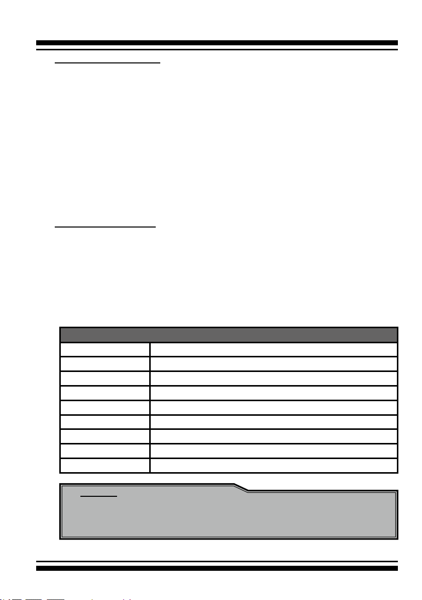
Front Side
Back Side
Figure 2-1, ARC-1203-2i 6Gb/s SATA RAID controller
Connector Type Description
1. (J1) Battery Backup Module Connector 14-pin wafer connector
2. (J2) Global Fault/Activity LED Header 4-pin header
3. (J3) Individual Fault/Activity LED Header 4-pin header
4. (J4) I2C/LCD Connector 7-pin header
5. (J5) Manufacture Purpose Port 14-pin header
6. (SCN1) SATA Port 1 (CH2) SATA III
7. (SCN2) SATA Port 0 (CH1) SATA III
8. (D3) Fault/Activity LED (for CH1) Bi-color DIP
9. (D4) Fault/Activity LED (for CH2) Bi-color DIP
Table 2-1, ARC-1203-2i connectors
15

HARDWARE INSTALLATION
Tools Required
An ESD grounding strap or mat is required. Also required are stan-
dard hand tools to open your system’s case.
System Requirement
The 6Gb/s SATA RAID controller can be installed in an universal
PCIe slot and requires a motherboard that:
ARC-1203-2i 6Gb/s SATA RAID controller requires:
• Comply with the PCIe 2.0 x1 lane
• Backward-compatibe with PCIe 1.0
The SATA RAID controller may be connected to up to 2 cables.
Optional cables are required to connect any drive activity LEDs and
fault LEDs on the enclosure to the SATA RAID controller.
Installation Tools
The following items may be needed to assist with installing the 6Gb/s
SATA RAID controller into an available PCIe expansion slot.
• Small screwdriver
• Host system hardware manuals and manuals for the disk or enclo-
sure being installed.
Personal Safety Instructions
Use the following safety instructions to help you protect your
computer system from potential damage and to ensure your own
personal safety.
• Always wear a grounding strap or work on an ESD-protective
mat.
• Before opening the system cover, turn off power switches and
unplug the power cords. Do not reconnect the power cords until
you have replaced the covers.
16
HARDWARE INSTALLATION
Electrostatic Discharge
Static electricity can cause serious damage to the electronic components on this 6Gb/s SATA RAID controller. To avoid damage
caused by electrostatic discharge, observe the following precautions:
• Do not remove the 6Gb/s SATA RAID controller from its anti-static packaging until you are ready to install it into a computer case.
• Handle the 6Gb/s SATA RAID controller by its edges or by the
metal mounting brackets at its each end.
• Before you handle the 6Gb/s SATA RAID controller in any way,
touch a grounded, anti-static surface, such as an unpainted portion of the system chassis, for a few seconds to discharge any
built-up static electricity.
Warning:
High voltages may be found inside computer equipment. Before installing any of the hardware in this package or removing the protective covers of any computer equipment, turn off
power switches and disconnect power cords. Do not reconnect
the power cords until you have replaced the covers.
17

HARDWARE INSTALLATION
2.3 Installation
Use the following instructions below to install a PCIe 2.0 6Gb/s
SATA RAID controller.
Step 1. Unpack
Unpack and remove the PCIe 2.0 6Gb/s SATA RAID controller from
the package. Inspect it carefully, if anything is missing or damaged,
contact your local dealer.
Step 2. Power PC/Server Off
Turn off computer and remove the AC power cord. Remove the sys-
tem’s cover. For the instructions, please see the computer system
documentation.
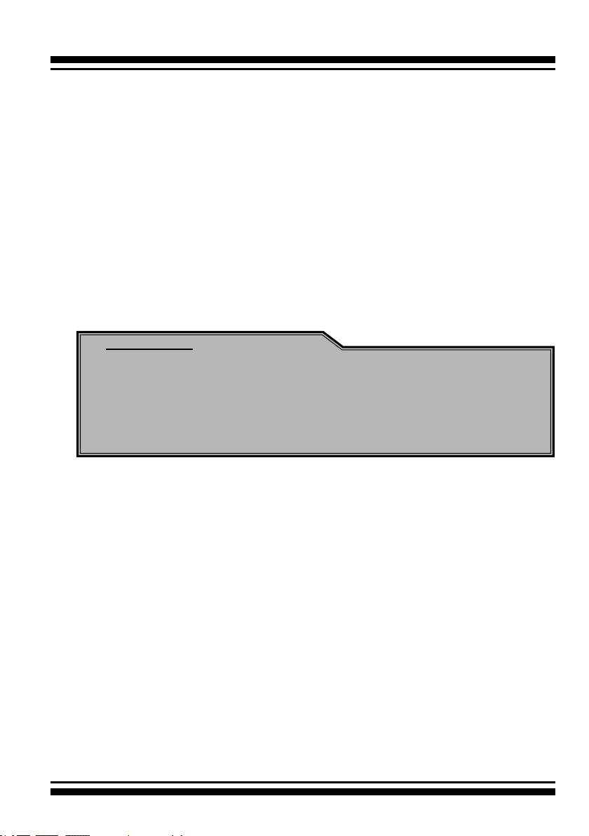
Step 3. Install the PCIe 6Gb/s SATA RAID Cards
To install the 6Gb/s SATA RAID controller, remove the mounting
screw and existing bracket from the rear panel behind the selected
PCIe 2.0 slot. Align the gold-ngered edge on the card with the
selected PCIe 2.0 slot. Press down gently but rmly to ensure that
the card is properly seated in the slot, as shown on Figure 2-2.
Then, screw the bracket into the computer chassis.
18
Figure 2-2, Insert into a
PCIe slot

HARDWARE INSTALLATION
Step 4. Mount the Drives
You can connect the SATA drives to the controller through direct
cable. In the direct connection, SATA drives are directly connected
to 6Gb/s SATA RAID controller port with SATA cables. The 6Gb/s
SATA RAID controller can support up to 2 ports. Remove the front
bezel from the computer chassis and install the cages or SATA
drives in the computer chassis. Loading drives to the drive tray
if cages are installed. Be sure that the power is connected to the
individual drives.
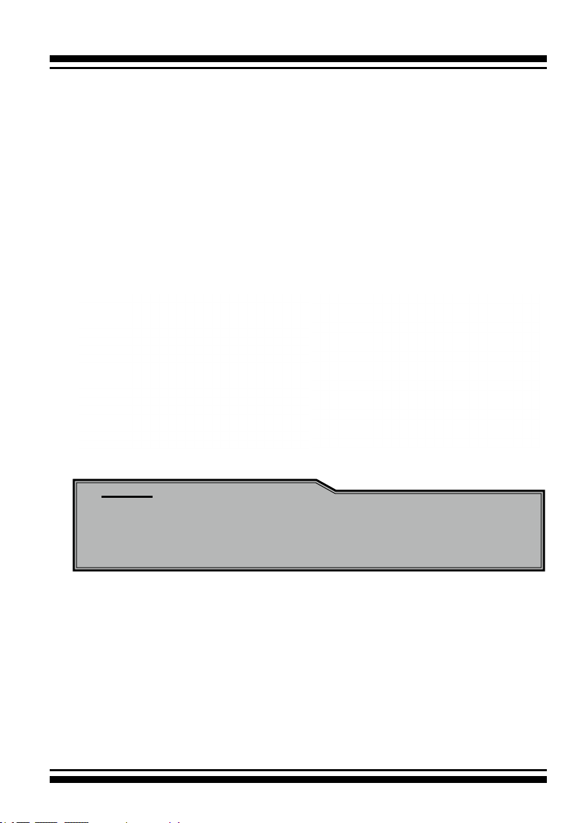
Step 5. Connect the SATA Cable
ARC-1203-2I controller has two SATA internal connectors. If you
have not yet connected your SATA cables, use the cables included
with your kit to connect the controller to the SATA hard drives.
The cable connectors are all identical, so it does not matter which
end you connect to your controller, SATA hard drive, or cage backplane SATA connector.
Figure 2-3, SATA Cable
Note:
The SATA cable connectors must match your HDD cage.
For example: Channel 1 of RAID controller connects to channel 1 of HDD cage, channel 2 of RAID controller connects to
channel 2 of HDD cage, and follow this rule.
19
HARDWARE INSTALLATION
Step 6. Install the LED Cable (Optional)
The 6Gb/s SATA controller provides LED cable header to support
the fault/activity status. The global indicator connector is used by
the server/desktop system global indicator LED.
The following electronics schematic is the 6Gb/s SATA RAID controller logical of fault/activity header. The signal from EPLD CTL
output pin is cathode (-) side.
The following diagrams and descriptions describe each type of connector.
Note:
A cable for the global indicator comes with your computer
system. Cables for the individual drive LEDs may come with a
drive cage, or you may need to purchase them.
A: Individual Fault LED and Global Activity/Fault Indicator
Connector
The 6Gb/s SATA RAID controller provides the connector for fault/
activity LED . Connect the cables for the fault/activity LEDs and the
respective connector on the 6Gb/s SATA RAID controller.
The following table is the fault/activity LED signal behavior.
20

HARDWARE INSTALLATION
LED Normal Status Problem Indication
HDD (Activity)
LED
Fault LED When the fault LED is solid
If the system will use only a single global indicator, attach the LED
to the two pins of the global activity/fault connector. The global
fault pin pair connector is the overall activity/fault signal.
When the activity (HDD)
LED is illuminated, there
is I/O activity on that disk
drive. When the activity
LED is dark, there is no
activity on that disk drive.
illuminated, there is no
disk present and When the
fault LED is off, that disk
is present and status is
normal.
When the "Identify Drive"
is selected, the selected
drive fault LED will blank.
N/A
When the fault LED is slow blinking (2 times/sec), that indicate
disk drive has failed and should be
hot-swapped immediately.
When the activity (HDD) LED is
illuminated and fault LED is fast
blinking (10 times/sec) that indicate there is rebuilding activity on
the disk drive.
Figure 2-4, ARC-1203-2i individual Fault/Activity LED
for each channel drive and global indicator
connector for computer case.
21
HARDWARE INSTALLATION
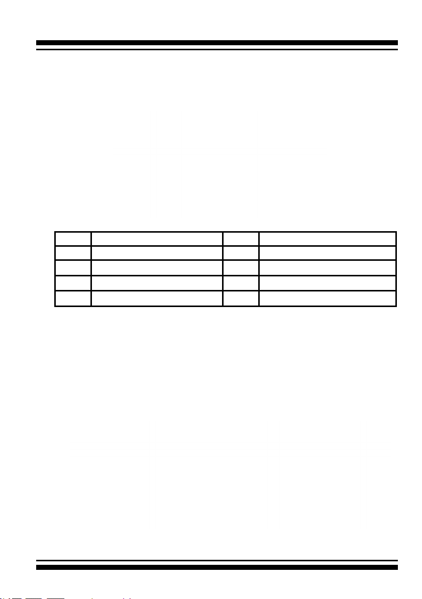
B: Areca Serial Bus Connector
The following picture and table is the serial bus signal name description for the LCD/I2C Module Connector (J4).
PIN Description PIN Description
1 Power (+5V) 2 GND
3 LCD Module Interrupt 4 Protect Key
5 LCD Module Serial Data 6 Fault/Activity Clock
7 Fault/Activity Serial Data 8 LCD Module Clock
22
You can use one optional LCD front panel and keypad function
to simply create the RAID volume. The LCD status panel also
informs you the disk array’s current operating status at a glance.
The LCD conguration is described in a separate manual: RAID
Card_LCD manual. The LCD housed in a 5¼-inch half-height or
3.5-inch canister.
Figure 2-5, Connect to LCD Status Panel

HARDWARE INSTALLATION
Step 7. Adding a Battery Backup Module (Optional)
Please refer to Appendix B Battery Backup Module (ARC-6120BA-
T121) for installing the BBM in your 6Gb/s SATA RAID controller.
Step 8. Re-check Fault LED Cable Connections (Optional)
Be sure that the proper failed drive channel information is displayed by the fault LEDs. An improper connection will tell the user
to ‘‘Hot Swap’’ the wrong drive. This can result in removing the
wrong disk (one that is functioning properly) from the controller.
This can result in failure and loss of system data.
Step 9. Power up the System
Throughly check the installation, reinstall the computer cover, and
reconnect the power cord cables. Turn on the power switch at the
rear of the computer (if equipped) and then press the power button
at the front of the host computer.
Step 10. Install the Controller Driver
For a new system:
• Driver installation usually takes places as part of operating sys-
tem installation. Please refer to Chapter 4 “Diver Installation” for
the detailed installation procedure.
For an existing system:
• To install the controller driver into the existing operating system.
For the detailed installation procedure, please refer to the Chapter 4, “Driver Installation”.
Step 11. Install ArcHTTP Proxy Server
The ARC-1203-2I rmware has embedded the web-browser
McRAID storage manager. ArcHTTP proxy server will launch the
web-browser McRAID storage manager. It provides all of the cre-
ation, management and monitor ARC-1203-2I RAID controller
status. Please refer to the Chapter 5 for the detail “ArcHTTP Proxy
Server Installation”. For SNMP agent function, please see the
“SNMP Operation & Installation” section in the Appendix C of the
user manual.
23

HARDWARE INSTALLATION
Step 12. Congure Volume Set
With Areca series RAID cards, there are 4 methods to manage your
ARC-1203-2I RAID controller. It can be congured by using the
LCD with keypad, McBIOS RAID manager (terminal emulation) or
McRAID storage manager (via ArcHTTP proxy utility).
• Method 1: Internal PCIe Connection (McBIOS RAID Manager)
The ARC-1203-2I RAID controller can be congured via a BIOS
start up McBIOS manager. The McBIOS RAID manager is rmware-based and is used to congure RAID sets and volume sets.
Because the utility resides in the ARC-1203-2I RAID controller
rmware, operation is independent of any operating systems
on your computer. For additional information on using the BIOS
on-screen to congure the RAID subsystem see the Chapter 3 of
“BIOS Conguration” of the user manual.
• Method 2: Internal PCIe Connection (McRAID Storage Manager)
You’re now ready to use the McRAID storage manager to set up
RAID volumes. Your ARC-1203-2I RAID controller can be cong-
ured by using McRAID storage manager (launched by ArcHTTP
proxy server). ARC-1203-2I RAID controller has embedded the
TCP/IP & web browser-based RAID manager in the rmware.
User can use the standard web browsers to manage the RAID
controller using ArcHTTP proxy server installed. For additional
information on using the McRAID storage manager to congure
the RAID controller see the Chapter 6 of “Web Browser-Based
Conguration” of the user manual.
• Method 3: Front LCD Panel with Keypad (Optional)
You can use LCD front panel and keypad function to simply create
the RAID volume. The LCD status panel also informs you of the
disk array’s current operating status at a glance. For additional
information on using the LCD to congure the RAID controller see
the ARC1000_LCD manual on the shipping CD. The LCD provides
a system of screens with areas for information, status indication,
or menus. The LCD screen displays up to two lines at a time of
menu items or other information.
24

HARDWARE INSTALLATION
Step 13. Format, Partition and Mount the ARC-1203-2I RAID
Controller Volumes
After the volume set is ready for system accesses, it needs to be
partitioned, formatted, and mounted by the operating system.
There are various steps, depending on what operating system you
are using (Windows, Linux, FreeBSD or Mac, etc.). Detailed steps
for each operating system are provided on their disk utility. After
that, the ARC-1203-2I RAID controller can be fully used.
Step 14. Determining the Boot Sequences
The ARC-1203-2I RAID controller is a bootable device. You can use
it as primary boot drive or secondary storage drive. If your system already contains a bootable device with an installed operating
system, you can set up your system to boot a second operating
system from the new ARC-1203-2I RAID controller volume.
For PC system:
To add a second bootable controller, you may need to enter setup
of motherboard BIOS and change the device boot sequence so that
the new ARC-1203-2I RAID controller volume heads the list. If the
system BIOS setup does not allow this change, your system may
be not congurable to allow the new ARC-1203-2I RAID controller
volume to act as a second boot device.
For Apple Mac Pro system:
Areca controller has supported the EFI BIOS on the PCIe 2.0 6Gb/s
SATA RAID controller. You have other alternatively to add volumes
on the Intel-based Mac bootable device listing. You can follow the
following procedures to add 6Gb/s SATA RAID controller on the Mac
bootable device listing.
1. Set the BIOS selection in System Controls: Advance Congura-
tion to “EFI” option for Intel-based MacPro boot.
2. Download OS X Mavericks and DiskMaker X. Follow the Disk-
Maker X to make a bootable OS X Mavericks USB install drive.
3. Restart your Mac and after you hear the chime sound, press
the Option (Alt) key until you see the option to choose the
ash drive to boot from.
25

HARDWARE INSTALLATION
4. Follow the on-screen prompts to complete Areca Volume
Upgrade and Clean Install of OS X Mavericks. Power up the
Intel-based Mac and Areca volume will be added in the
bootable device automatically.
2.4 Summary of the installation
The ow chart below describes the installation procedures for 6Gb/s
SATA RAID controllers.
These procedures includes hardware installation, the creation and
conguration of a RAID volume through the McBIOS/McRAID manager, OS installation and installation of 6Gb/s SATA RAID controller
software.
The software components congure and monitor the 6Gb/s SATA
RAID controllers as following table.
Conguration Utility Operating System Supported
McBIOS RAID Manager OS-Independent
McRAID Storage Manager
(Via ArcHTTP proxy server)
SAP Monitor (Single Admin Portal to
scan for multiple RAID units in the net-
work, via ArcHTTP proxy server)
SNMP Manager Console Integration Windows 10/8/2012/7/2008/Vista/
Windows 10/8/2012/7/2008/Vista/
XP(64-bit)/2003, Linux, FreeBSD, So-
laris and Mac
Windows 10/8/2012/7/2008/Vista/
XP(64-bit)/2003
XP(64-bit)/2003, Linux and FreeBSD
26

HARDWARE INSTALLATION
McRAID Storage Manager
Before launching the rmware-embedded web browser, McRAID
storage manager through the PCIe bus, you need rst to install the
ArcHTTP proxy server on your server system. If you need additional
information about installation and start-up of this function, see the
McRAID Storage Manager section in Chapter 6 of the user manual.
ArcHTTP Proxy Server
ArcHTTP has to be installed for GUI RAID console (MRAID storage
manager) to run. It is used to launch the web browser McRAID
storage manager. It also runs as a service or daemon in the background that allows capturing of events for mail and SNMP traps no-
tication. If you need additional information about installation and
start-up of this function, see the ArcHTTP Proxy Server Installation
section in Chapter 5 of the user manual.
CLI Utility
CLI (Command Line Interface) lets you set up and manage RAID
controller through a command line interface. CLI performs many
tasks at the command line. You can download CLI manual from
Areca website or software CD <CDROM>\DOCS directory.
SNMP Manager Console Integration
There are two ways to transport SNMP data on the ARC-1203-2I
RAID controller: in-band PCIe host bus interface or out-of-band
built-in LAN interface. Enter the “SNMP Tarp IP Address” option on
the rmware-embedded SNMP conguration function for user to select the SNMP data agent-side communication from the out-of-band
built-in LAN interface. To use in-band PCIe host bus interface, keep
blank on the “SNMP Tarp IP Address” options.
• In-Band-Using PCIe Host Bus Interface
In-band interface refers to management of the SNMP data of
6Gb/s SATA controllers from a PCIe host bus. In-band interface is
simpler than out-of-band interface for it requires less hardware in
its conguration.Since the 6Gb/s SATA RAID controller is already
installed in the host system, no extra connection is necessary.
27

HARDWARE INSTALLATION
Just load the necessary in-band Areca SNMP extension agent
for the controllers. Before launching the SNMP agent in the
sever, you need rst to enable the rmware-embedded SNMP
community conguration and install Areca SNMP extension agent
in your server system. If you need additional information about
installation and start-up the function, see the SNMP Operation &
Installation section in the Appendix C of the user manual.
Single Admin Portal (ArcSAP) Monitor
This utility can scan for multiple RAID units in the local and remote
systems and provide an effective mechanism to congure and
monitor your RAID units. For additional information, see the utility
manual (ArcSAP) in the packaged CD or download it from the web
site http://www.areca.com.tw
28
BIOS CONFIGURATION
3. McBIOS RAID Manager
The system mainboard BIOS automatically congures the following
6Gb/s SATA RAID controller parameters at power-up:
• I/O Port Address
• Interrupt Channel (IRQ)
• Controller ROM Base Address
Use McBIOS RAID manager to further congure the 6Gb/s SATA RAID
controller to suit your server hardware and operating system.
3.1 Starting the McBIOS RAID Manager
This section explains how to use the McBIOS RAID manager to
congure your RAID system. The McBIOS RAID manager is de-
signed to be user-friendly. It is a menu-driven program, residing
in the rmware, which allows you to scroll through various menus
and sub-menus and select among the predetermined conguration
options.
When starting a system with a 6Gb/s SATA RAID controller installed, it will display the following message on the monitor during
the start-up sequence (after the system BIOS startup screen but
before the operating system boots):
ARC-1203-2I PCIEx4/5.0G RAID Controller - DRAM: 1024(MB) / #Channels: 2
BIOS: V1.23 / Date: 2015-12-10 - F/W: V1.52 / Date: 2015-11-10
Bus/Dev/Fun= 8/0/0, I/0-Port=FBEA0000h, IRQ=10, BIOS=CA00 : 0h
ID-LUN=00-0, Vol=”Areca ARC-1203-VOL#000R001”, Size=3.6 (TB)
ID-LUN=00-1, Vol=”Areca ARC-1203-VOL#001R001”, Size=3.6 (TB)
RAID controller BIOS not installed
Press <Tab/F6> to enter SETUP menu. 9 second(s) left <ESC to Skip>..
The McBIOS RAID manager message remains on your screen for
about nine seconds, giving you time to start the conguration
menu by pressing Tab or F6. If you do not wish to enter conguration menu, press ESC to skip conguration immediately. When
activated, the McBIOS RAID manager window appears showing a
selection dialog box listing the 6Gb/s SATA RAID controllers that
are installed in the system. The legend at the bottom of the screen
shows you what keys are enabled for the windows.
29
BIOS CONFIGURATION
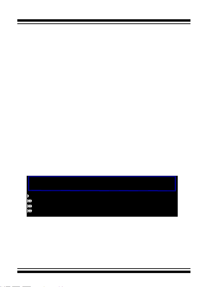
Areca Technology Corporation RAID Setup <V1.56, 2012/12/24>
Select An Adapter To Congure
( 001/ 0/0) I/O=28000000h, IRQ = 9
ArrowKey Or AZ:Move Cursor, Enter: Select, **** Press F10 (Tab) to Reboot ****
Use the Up and Down arrow keys to select the controller you want
to congure. While the desired controller is highlighted, press the
Enter key to enter the main menu of the McBIOS RAID manager.
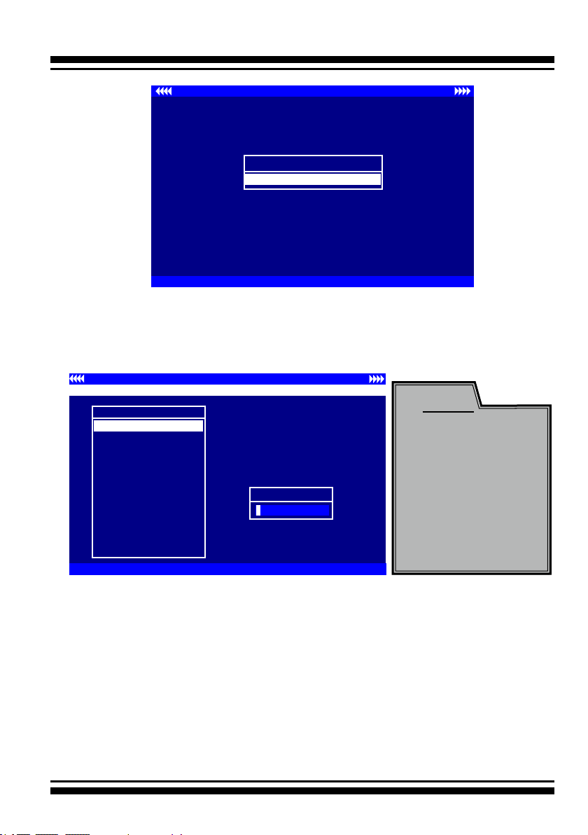
I/O Port Addr : 28000000h, F2(Tab): Select Controller, F10: Reboot System
ArrowKey Or AZ:Move Cursor, Enter: Select, ESC: Escape, L:Line Draw, X: Redraw
Areca Technology Corporation RAID Controller
Main Menu
Quick Volume/Raid Setup
Raid Set Function
Volume Set Function
Physical Drives
Raid System Function
More System Functions
Hdd Power Management
Ethernet Conguration
Alert By Mail Cong
View System Events
Clear Event Buffer
Hardware Monitor
System information
Verify Password
Note:
The manufacture
default password is
set to 0000; this
password can be
modied by selecting
Change Password
in the Raid System
Function section.
3.2 McBIOS RAID manager
The McBIOS RAID manager is rmware-based and is used to congure RAID sets and volume sets. Because the utility resides in the
6Gb/s SATA RAID controller rmware, operation is independent of
any operating systems on your computer. This utility can be used
to:
• Create RAID sets,
• Expand RAID sets,
30
 Loading...