


ARC-1110/1120/1130/1160/1170
( 4/8/12/16/24-port PCI-X SATA RAID Adapter )
ARC-1110ML/1120ML/1130ML/1160ML
( 4/8-port Innband connector and 12/16-port Multi-lane
connector PCI-X SATA RAID Adapter )
ARC-1210/1220/1230/1260/1280
( 4/8/12/16/24-port PCI-Express SATA RAID Adapter )
ARC-1230ML/1260ML/1280ML
(12/16/24-port PCI-Express SATA RAID Adapter)
SATA RAID Cards
USER Manual
Version: 3.2
Issue Date: August, 2006

Microsoft WHQL Windows Hardware Compatibility
Test
ARECA is committed to submitting products to the Microsoft Windows
Hardware Quality Labs (WHQL), which is required for participation in the
Windows Logo Program. Successful passage of the WHQL tests results
in both the “Designed for Windows” logo for qualifying ARECA PCI-X and
PCI-Express SATA RAID controllers and a listing on the Microsoft Hardware Compatibility List (HCL).
Copyright and Trademarks
The information of the products in this manual is subject to change
without prior notice and does not represent a commitment on the part
of the vendor, who assumes no liability or responsibility for any errors
that may appear in this manual. All brands and trademarks are the
properties of their respective owners. This manual contains materials
protected under International Copyright Conventions. All rights
reserved. No part of this manual may be reproduced in any form or by
any means, electronic or mechanical, including photocopying, without
the written permission of the manufacturer and the author. All inquiries
should be addressed to ARECA Technology Corp.
FCC STATEMENT
This equipment has been tested and found to comply with the limits for
a Class B digital device, pursuant to part 15 of the FCC Rules. These
limits are designed to provide reasonable protection against interference in a residential installation. This equipment generates, uses, and
can radiate radio frequency energy and, if not installed and used in accordance with the instructions, may cause harmful interference to radio
communications. However, there is no guarantee that interference will
not occur in a particular installation.

Contents
1. Introduction .............................................................. 10
1.1 Overview ....................................................................... 10
1.2 Features ........................................................................ 12
1.3 RAID Concept ................................................................. 15
1.3.1 RAID Set ................................................................... 15
1.3.2 Volume Set ................................................................15
1.3.3 Ease of Use Features ................................................. 16
1.3.3.1 Instant Availability/Background Initialization ............ 16
1.3.3.2 Array Roaming ..................................................... 16
1.3.3.3 Online Capacity Expansion ..................................... 17
1.3.3.4 Online RAID Level and Stripe Size Migration ............. 19
1.3.3.5 Online Volume Expansion ........................................ 19
1.4 High availability .............................................................. 20
1.4.1 Global Hot Spares ...................................................... 20
1.4.2 Hot-Swap Disk Drive Support ....................................... 21
1.4.3 Auto Declare Hot-Spare .............................................. 21
1.4.4 Auto Rebuilding ......................................................... 21
1.4.5 Adjustable Rebuild Priority ........................................... 22
1.5 High Reliability ................................................................23
1.5.1 Hard Drive Failure Prediction ........................................ 23
1.5.2 Auto Reassign Sector .................................................. 23
1.5.3 Consistency Check ...................................................... 24
1.6 Data Protection ............................................................... 24
1.6.1 BATTERY BACKUP ...................................................... 24
1.6.2 RECOVERY ROM ......................................................... 25
1.7 Understanding RAID ........................................................ 25
1.7.1 RAID 0 ...................................................................... 25
1.7.2 RAID 1 ...................................................................... 26
1.7.3 RAID 1E .................................................................... 27
1.7.4 RAID 3 ...................................................................... 27
1.7.5 RAID 5 ...................................................................... 28
1.7.6 RAID 6 ...................................................................... 29
2. Hardware Installation ............................................... 31
2.1 Before Your begin Installation ........................................... 31
2.2 Board Layout .................................................................. 32
2.3 Installation ..................................................................... 37
3. McBIOS RAID Manager .............................................. 53

3.1 Starting the McBIOS RAID Manager ................................... 53
3.2 McBIOS Conguration manager ......................................... 54
3.3 Conguring Raid Sets and Volume Sets .............................. 55
3.4 Designating Drives as Hot Spares ...................................... 55
3.5 Using Quick Volume /Raid Setup Conguration .................... 56
3.6 Using RAID Set/Volume Set Function Method ...................... 57
3.7 Main Menu .................................................................... 59
3.7.1 Quick Volume/RAID Setup ........................................... 60
3.7.2 Raid Set Function ....................................................... 63
3.7.2.1 Create Raid Set .................................................... 64
3.7.2.2 Delete Raid Set ..................................................... 65
3.7.2.3 Expand Raid Set .................................................... 65
• Migrating ...................................................................... 66
3.7.2.4 Activate Incomplete Raid Set ................................... 67
3.7.2.5 Create Hot Spare ................................................... 68
3.7.2.6 Delete Hot Spare ................................................... 68
3.7.2.7 Raid Set Information .............................................. 69
3.7.3 Volume Set Function ................................................... 69
3.7.3.1 Create Volume Set ................................................. 70
• Volume Name ................................................................ 72
• Raid Level ..................................................................... 72
• Capacity ....................................................................... 73
• Strip Size ...................................................................... 74
• SCSI Channel ................................................................ 75
• SCSI ID ........................................................................ 75
• SCSI LUN ...................................................................... 76
• Cache Mode .................................................................. 76
• Tag Queuing .................................................................. 77
3.7.3.2 Delete Volume Set ................................................. 77
3.7.3.3 Modify Volume Set ................................................. 78
• Volume Growth .............................................................. 79
• Volume Set Migration ...................................................... 79
3.7.3.4 Check Volume Set .................................................. 80
3.7.3.5 Stop Volume Set Check .......................................... 80
3.7.3.6 Display Volume Set Info. ........................................ 81
3.7.4 Physical Drives ........................................................... 82
3.7.4.1 View Drive Information .......................................... 82
3.7.4.2 Create Pass-Through Disk ....................................... 83
3.7.4.3 Modify a Pass-Through Disk ..................................... 83
3.7.4.4 Delete Pass-Through Disk .......................................84
3.7.4.5 Identify Selected Drive ........................................... 84
3.7.5 Raid System Function ................................................. 85

3.7.5.1 Mute The Alert Beeper ........................................... 85
3.7.5.2 Alert Beeper Setting ............................................... 86
3.7.5.3 Change Password .................................................. 86
3.7.5.4 JBOD/RAID Function .............................................. 87
3.7.5.5 Background Task Priority ........................................ 88
3.7.5.6 Maximum SATA Mode ............................................. 88
3.7.5.7 HDD Read Ahead Cache ......................................... 89
3.7.5.8 Stagger Power On .................................................. 89
3.7.5.9 Empty HDD slot HDD .............................................90
3.7.5.10 HDD SMART Status Polling .................................... 91
3.7.5.11 Controller Fan Detection ....................................... 91
3.7.5.12 Disk Write Cache Mode ......................................... 92
3.7.5.13 Capacity Truncation .............................................. 92
3.7.6 Ethernet Conguration (12/16/24-port) ......................... 93
3.7.6.1 DHCP Function ...................................................... 94
3.7.6.2 Local IP address .................................................... 95
3.7.6.3 Ethernet Address ................................................... 96
3.7.7 View System Events ................................................... 96
3.7.8 Clear Events Buffer ..................................................... 97
3.7.9 Hardware Monitor ....................................................... 97
3.7.10 System Information .................................................. 97
4. Driver Installation ..................................................... 99
4.1 Creating the Driver Diskettes ............................................ 99
4.2 Driver Installation for Windows ....................................... 100
4.2.1 New Storage Device Drivers in Windows Server 2003 .... 100
4.2.2 Install Windows 2000/XP/2003 on a SATA RAID Volume 101
4.2.2.1 Installation procedures ......................................... 101
4.2.2.2 Making Volume Sets Available to Windows System ... 102
4.2.3 Installing controller into an existing Windows 2000/XP/2003
Installation ...................................................................... 103
4.2.3.1 Making Volume Sets Available to Windows System ... 104
4.2.4 Uninstall controller from Windows 2000/XP/2003 .......... 105
4.3 Driver Installation for Linux ............................................ 106
4.4 Driver Installation for FreeBSD ........................................ 106
4.5 Driver Installation for Solaris .......................................... 107
4.6 Driver Installation for Mac X ........................................... 107
5. ArcHttp Proxy Server Installation ........................... 108
5.1 For Windows................................................................. 109
5.2 For Linux ..................................................................... 110
5.3 For FreeBSD ................................................................. 111
5.4 For Solaris 10 X86 ......................................................... 111

5.5 For Mac OS 10.X ........................................................... 111
5.6 Email Notication .......................................................... 111
5.6.1 Start-up Mail Conguration for Local8Administration ..... 111
5.6.1.1 For Windows ....................................................... 111
5.6.1.2 For Linux/FreeBSD ............................................... 112
5.6.2 Start-up Mail Conguration for RemoteAdministration .... 112
• SMTP Server Conguration ............................................ 113
• Mail Address Congurations ........................................... 113
• Event Notication Congurations .................................... 113
A. Device Event .............................................................. 114
B. Volume Event ............................................................. 114
C. RaidSet Event ............................................................ 115
D. Hardware Event .......................................................... 115
6. Web Browser-based Conguration ......................... 116
6.1 Start-up McRAID Storage Manager ................................. 116
• Another method to start-up McRAID Storage Manager from
Windows Local Administration .......................................... 117
6.1.1 Through Ethernet port (Out-of-Band) ......................... 118
6.2 SATA RAID controller McRAID Storage Manager ................. 119
6.3 Main Menu .................................................................. 120
6.4 Quick Function .............................................................. 120
6.5 RaidSet Functions ......................................................... 121
6.5.1 Create Raid Set ....................................................... 121
6.5.2 Delete Raid Set ........................................................ 122
6.5.3 Expand Raid Set ....................................................... 123
6.5.4 Activate Incomplete Raid Set ..................................... 123
6.5.5 Create Hot Spare ..................................................... 124
6.5.6 Delete Hot Spare ...................................................... 124
6.5.7 Rescue Raid Set ....................................................... 124
6.6 Volume Set Functions .................................................... 125
6.6.1 Create Volume Set ................................................... 125
• Volume Name .............................................................. 126
• Raid Level .................................................................. 126
• Capacity ..................................................................... 126
• Greater Two TB Volume Support ..................................... 126
• Initialization Mode ........................................................ 127
• Strip Size .................................................................... 127
• Cache Mode ................................................................ 127
• SCSI Channel/SCSI ID/SCSI Lun .................................... 127
• Tag Queuing ................................................................ 127
6.6.2 Delete Volume Set .................................................... 128

6.6.3 Modify Volume Set .................................................... 128
6.6.3.1 Volume Set Migration ........................................... 128
6.6.4 Check Volume Set .................................................... 129
6.6.5 Stop VolumeSet Check .............................................. 130
6.7 Physical Drive .............................................................. 130
6.7.1 Create Pass-Through Disk .......................................... 130
6.7.2 Modify Pass-Through Disk .......................................... 131
6.7.3 Delete Pass-Through Disk .......................................... 132
6.8 System Controls ........................................................... 133
6.8.1 System Cong ......................................................... 133
• System Beeper Setting ................................................. 133
• Background Task Priority ............................................... 133
• JBOD/RAID Conguration .............................................. 133
• Maximun SATA Supported ............................................. 133
• HDD Read Ahead Cache ................................................ 133
• Stagger Power on ........................................................ 134
• Empty HDD Slot LED .................................................... 135
• HDD SMART Status Polling............................................. 135
• Disk Write Cache Mode ................................................. 136
• Disk Capacity Truncation Mode ....................................... 136
6.8.2 Ethernet Conguration (12/16/24-port) ....................... 137
6.8.3 Alert by Mail Conguration (12/16/24-port) ................ 138
6.8.4 SNMP Conguration (12/16/24-port) ........................... 139
• SNMP Trap Congurations ............................................. 140
• SNMP System Congurations ......................................... 140
• SNMP Trap Notication Congurations ............................. 140
6.8.5 NTP Conguration (12/16/24-port) ............................. 140
• NTP Sever Address ....................................................... 140
• Time Zone ................................................................... 141
• Automatic Daylight Saving............................................. 141
6.8.6 View Events/Mute Beeper .......................................... 141
6.8.7 Generate Test Event ................................................. 141
6.8.8 Clear Events Buffer ................................................... 142
6.8.9 Modify Password ...................................................... 142
6.8.10 Update Firmware ................................................... 143
6.9 Information .................................................................. 143
6.9.1 RaidSet Hierarchy ..................................................... 143
6.9.2 System Information .................................................. 143
6.9.3 Hardware Monitor ..................................................... 145
Appendix A ................................................................. 146
Upgrading Flash ROM Update Process .................................... 146

Upgrading Firmware Through McRAID Storage Manager ........... 146
Upgrading Entire Flash ROM ImageThrough Arcash DOS Utility 147
Appendix B .................................................................. 150
Battery Backup Module (ARC-1620-BAT) ................................ 150
BBM Components ........................................................... 150
BBM Specications .......................................................... 150
Installation .................................................................... 151
Battery Backup Capacity .................................................. 151
Operation ...................................................................... 152
Changing the Battery Backup Module ................................ 152
Appendix C .................................................................. 153
SNMP Operation & Denition ................................................ 153
Appendix D .................................................................. 160
General Troubleshooting Tips ............................................... 160
Appendix E .................................................................. 164
Technical Support ............................................................... 164
Glossary ...................................................................... 165
2TB .............................................................................. 165
Array ............................................................................ 165
ATA .............................................................................. 165
Auto Reassign Sector ..................................................... 165
Battery Backup Module .................................................... 166
BIOS ............................................................................ 166
Cache ........................................................................... 166
Consistency Check .......................................................... 166
Driver ........................................................................... 166
Hot Spare ...................................................................... 167
Hardware RAID versus Software RAID .............................. 167
Hot Swap ...................................................................... 167
NVRAM .......................................................................... 167
Parity ............................................................................ 167
PCI Express .................................................................. 167
PCI-X ........................................................................... 168
RAID ............................................................................ 168
Rebuild ......................................................................... 168
SATA (Serial ATA) ........................................................... 168
SMART .......................................................................... 169
SNMP ............................................................................ 169
Volume Set .................................................................... 169
Write-back ..................................................................... 169
Write-through ................................................................ 169

XOR-Engine ................................................................... 170

INTRODUCTION
10
1. Introduction
This section presents a brief overview of the SATA RAID Series controller cards, ARC-1110/1110ML/1120/1120ML/1130/1130ML/1160/
1160ML/1170 (4/8/12/16/24-port PCI-X SATA RAID Controllers) and
ARC-1210/1220/1230/1230/1230ML/1260/1260ML/1280/1280ML
(4/8/12/16/24-port PCI-Express SATA RAID Controllers).
1.1 Overview
The ARC-11xx and ARC-12xx Series of high-performance Serial ATA
RAID controllers support a maximum of 4, 8, 12, 16, or 24 SATAII peripheral devices (depending on model) on a single controller
card. The ARC-11xx Series are for the PCI-X bus and the ARC-12xx
Series are for the PCI-Express bus. When properly congured,
these SATA controllers can provide non-stop service with a high
degree of fault tolerance through the use Of RAID technology and
can also provide advanced array management features.
The 4 and 8 port SATA RAID controllers are low-prole PCI cards,
ideal for 1U and 2U rack-mount systems. These cards utilize the
same RAID kernel that has been eld-proven in existing external
RAID controller products, allowing Areca to quickly bring stable and
reliable RAID controllers to the market.
Unparalleled Performance
Areca RAID controllers provide reliable data protection for desktops, workstations, and servers. These cards set the standard with
enhancements that include a high-performance Intel I/O Processor, a new DDR333 memory architecture, and a high performance
PCI bus interconnection. SATA RAID 8/12/16/24-port controllers
with the Areca RAID 6 engine built-in can offer extreme-availability
RAID 6 functionality. This engine can concurrently computes two
parity blocks with performance very similar to RAID 5. The controllers by default support 256MB of ECC DDR333 SDRAM memory.
The 12/16/24 port controllers support one DDR333 SODIMM socket
that allows for upgrading up to 1GB of memory. The 12/16/24
port controllers support one DDR2-533 DIMM socket that allows
for upgrading up to 2GB of memory. The controllers use Marvell

INTRODUCTION
11
4/8 channel SATA PCI-X controller chips, which can simultaneously
communicate with the host system and read or write data on multiple drives.
Unsurpassed Data Availability
As storage capacity requirements continue to rapidly increase, users require greater levels of disk drive fault tolerance, which can be
implemented without doubling the investment in disk drives. RAID
1 (mirroring) provides high fault tolerance. However, half of the
drive capacity of the array is lost to mirroring, making it too costly
for most users to implement on large volume sets due to dobuling
the number of drives required. Users want the protection of RAID 1
or better with an implementation cost comparable to RAID 5. RAID
6 can offer fault tolerance greater than RAID 1 or RAID 5 but only
consumes the capacity of 2 disk drives for distributed parity data.
The 8/12/16/24-port RAID controllers provide RAID 6 functionality
to meet these demanding requirements.
The 4/8/12/16/24-port controllers also provide RAID levels 0, 1,
1E, 3, 5, and JBOD congurations. Its high data availability and
protection is derived from the following capabilities: Online RAID
Capacity Expansion, Array Roaming, Online RAID Level / Stripe
Size Migration, Dynamic Volume Set Expansion, Global Online
Spare, Automatic Drive Failure Detection, Automatic Failed Drive
Rebuilding, Disk Hot-Swap, Online Background Rebuilding and
Instant Availability/Background Initialization. During the controller
rmware ash upgrade process, it is possible that an error results
in corruption of the controller rmware. This could result in the device becoming non-functional. However, with our Redundant Flash
image feature, the controller will revert back to the last known
version of rmware and continue operating. This reduces the risk of
system failure due to rmware crashes.
Easy RAID Management
The SATA RAID controller utilizes built-in rmware with an embedded terminal emulation that can access via hot key at BIOS bootup screen. This pre-boot manager utility can be used to simplify
the setup and management of the RAID controller. The controller
rmware also contains a HTTP browser-based program that can be

INTRODUCTION
12
accessed through the ArcHttp Proxy Server function in Windows,
Linux and FreeBSD environments. This Web browser-based RAID
management utility allows both local and remote creation and
modication RAID sets, volume sets, and monitoring of RAID status
from standard web browsers.
1.2 Features
Adapter Architecture
• Intel IOP 331 I/O processor (ARC-11xx series)
• Intel IOP 332/IOP 333 I/O processor (ARC-12xx series)
• Intel 81341 I/O processor (ARC-12x0ML/1280)
• 64-bit/133MHz PCI-X Bus compatible
• PCI Express X8 compatible
• 256MB on-board DDR333 SDRAM with ECC protection (4/8-port)
• One SODIMM Socket with default 256 MB of DDR333 SDRAM
with ECC protection, upgrade to 1GB (12, 16 and 24-port cards
only)
• One DIMM Socket with default 256 MB of DDR2-533 SDRAM
with ECC protection, upgrade to 2GB(ARC-12xxML, ARC-1280)
• An ECC or non-ECC SDRAM module using X8 or X16 devices
• Support up to 4/8/12/16/24 SATA ll drives
• Write-through or write-back cache support
• Multi-adapter support for large storage requirements
• BIOS boot support for greater fault tolerance
• BIOS PnP (plug and play) and BBS (BIOS boot specication)
support
• Supports extreme performance Intel RAID 6 functionality
• NVRAM for RAID event & transaction log
• Battery backup module (BBM) ready (Depend on mother
board)
RAID Features
• RAID level 0, 1, 1E, 3, 5, 6 (R6 engine inside) and JBOD
• Multiple RAID selection
• Array roaming
• Online RAID level/stripe size migration
• Online capacity expansion RAID level migration simultaneously
• Online Volume set growth
• Instant availability and background initialization
• Automatic drive insertion / removal detection and rebuilding
• Greater than 2TB per volume set for 64-bit LBA

INTRODUCTION
13
• Redundant ash image for adapter availability
• Support S.M.A.R.T, NCQ and OOB Staggered Spin-up Capable
drives
Monitors/Notication
• System status indication through LED/LCD connector, HDD
activity/fault connector, and alarm buzzer
• SMTP support for email notication
• SNMP agent supports for remote SNMP Manager
• I2C Enclosure Management Ready (IOP 331/332/333)
• I2C & SGPIO Enclosure Management Ready (81341)
RAID Management
• Field-upgradeable rmware in ash ROM
• Ethernet port support on 12/16/24-port
In-Band Manager
• Hot key boot-up McBIOS RAID manager via BIOS
• Support controller’s API library, allowing customer to write cus tom AP
• Support Command Line Interface (CLI)
• Browser-based management utility via ArcHttp Proxy Server
• Single Admin Portal (SAP) monitor utility
• Disk Stress Test (DST) utility for production in Windows
Out-of-Band Manager
• Firmware-embedded Browser-based RAID manager, SMTP
manager, SNMP agent and Telnet function via Ethernet port
(for 12/16/24-port Adapter)
• Support controller’s API library for customer to write its own
AP (for 12/16/24-port Adapter)
• Push Button and LCD display panel
Operating System
• Windows 2000/XP/Server 2003
• Red Hat Linux
• SuSE Linux
• FreeBSD
• Novell Netware 6.5
• Solaris 10 X86/X86_64
• SCO Unixware 7.X.X
• Mac OS 10.X (no_bootable)
(For latest supported OS listing visit http://www.areca.com.tw)
INTRODUCTION
14
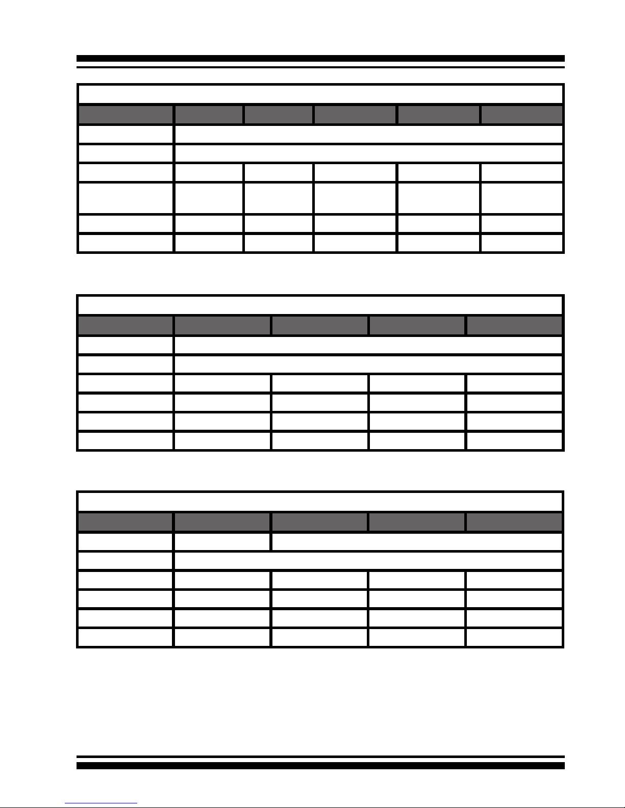
Internal PCI-X RAID Card Comparison (ARC-11XXML)
1110ML 1120ML 1130ML 1160ML
RAID processor IOP331
Host Bus Type PCI-X 133MHz
RAID 6 support N/A YES YES YES
Cache Memory 256MB 256MB One SODIMM One SODIMM
Drive Support 4 * SATA ll 8 * SATA ll 12 * SATA ll 16 * SATA ll
Disk Connector Innband Innband Multi-lane Multi-lane
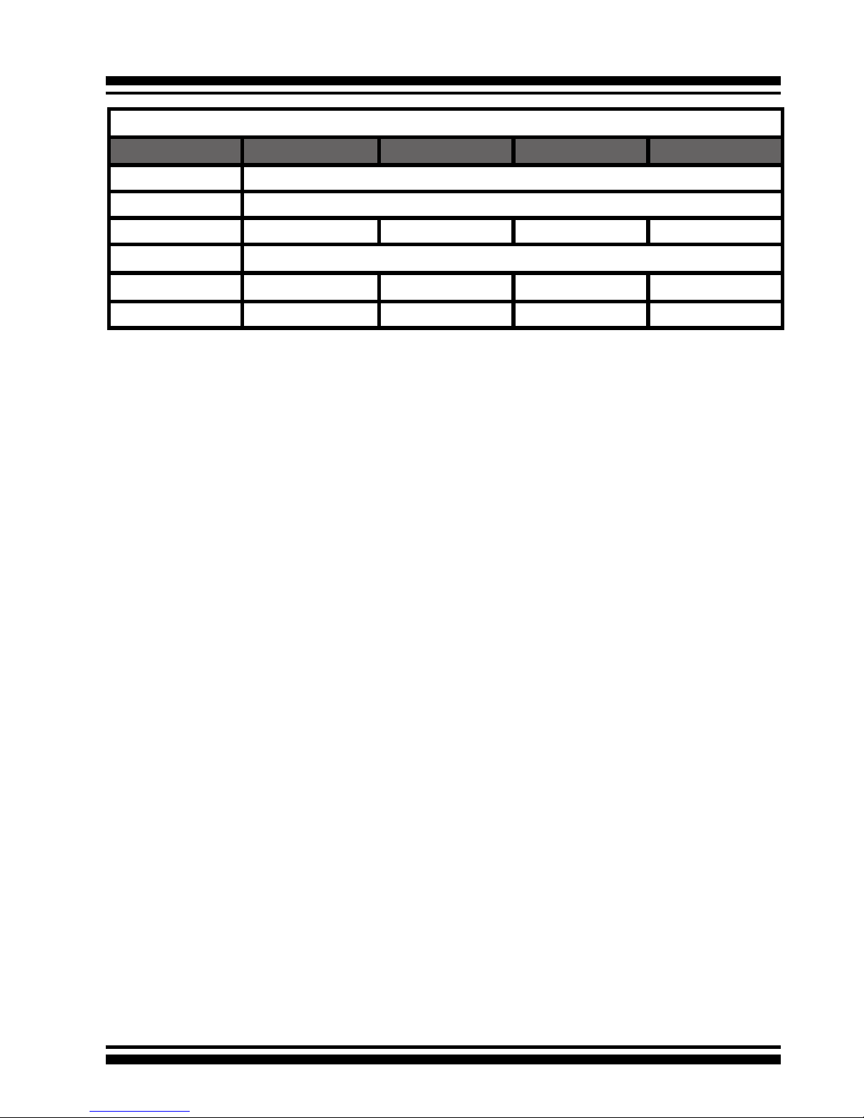
Internal PCI-Express RAID Card Comparison (ARC-12XX)
1210 1220 1230 1260
RAID processor IOP333
Host Bus Type PCI-Express X8
RAID 6 support N/A YES YES YES
Cache Memory 256MB 256MB One SODIMM One SODIMM
Drive Support 4 * SATA ll 8 * SATA ll 12 * SATA ll 16 * SATA ll
Disk Connector SATA SATA SATA SATA
IOP332
Internal PCI-X RAID Card Comparison (ARC-11XX)
1110 1120 1130 1160 1170
RAID processor IOP331
Host Bus Type PCI-X 133MHz
RAID 6 support N/A YES YES YES YES
Cache Memory 256MB 256MB One SO-
DIMM
One SO-
DIMM
One SO-
DIMM
Drive Support 4 * SATA ll 8 * SATA ll 12 * SATA ll 16 * SATA ll 24 * SATA ll
Disk Connector SATA SATA SATA SATA SATA
INTRODUCTION
15
1.3 RAID Concept
1.3.1 RAID Set
A RAID Set is a group of disks connected to a RAID controller. A
RAID Set contains one or more Volume Sets. The RAID Set itself
does not dene the RAID level (0, 1, 1E, 3, 5, 6, etc); the RAID
level is dened within each Volume Set. So, Volume Sets are contained within RAID Sets and the RAID Level is dened within the
Volume Set. If physical disks of different capacities are grouped
together in a RAID Set, then the capacity of the smallest disk will
become the effective capacity of all the disks in the RAID Set.
1.3.2 Volume Set
Each Volume Set is seen by the host system as a single logical
device (in other words, a single large virtual hard disk). A Volume
Set will use a specic RAID level, which will require one or more
physical disks (depending on the RAID level used). RAID level
refers to the level of performance and data protection of a Volume
Set. The capacity of a Volume Set can consume all or a portion
of the available disk capacity in a RAID Set. Multiple Volume Sets
can exist in a Raid Set.
For the SATA RAID controller, a volume set must be created either
on an existing RAID Set or on a group of available individual disks
(disks that are about to become part of a raid set). If there are
pre-existing RAID Sets with available capacity and enough disks
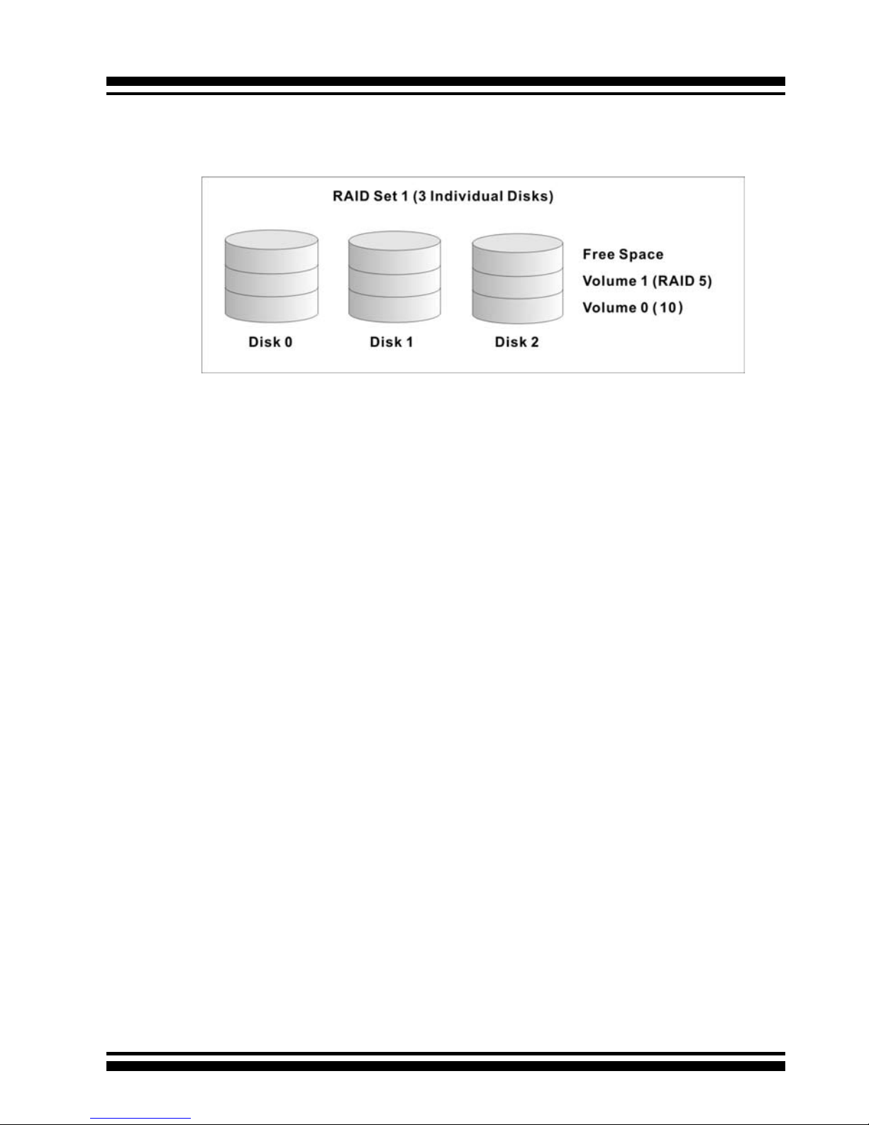
Internal PCI-Express RAID Card Comparison (ARC-12XX)
1230ML 1260ML 1280ML 1280
RAID processor IOP341
Host Bus Type PCI-Express X8
RAID 6 support YES YES YES YES
Cache Memory One DDR2 DIMM (Default 256MB, Upgrade to 2GB)
Drive Support 12 * SATA ll 16 * SATA ll 24 * SATA ll 24 * SATA ll
Disk Connector 3*Min SAS 4i 4*Min SAS 4i 6*Min SAS 4i 24*SATA
INTRODUCTION
16
for the desired RAID level, then the volume set can be created in
the existing raid set of the user’s choice.
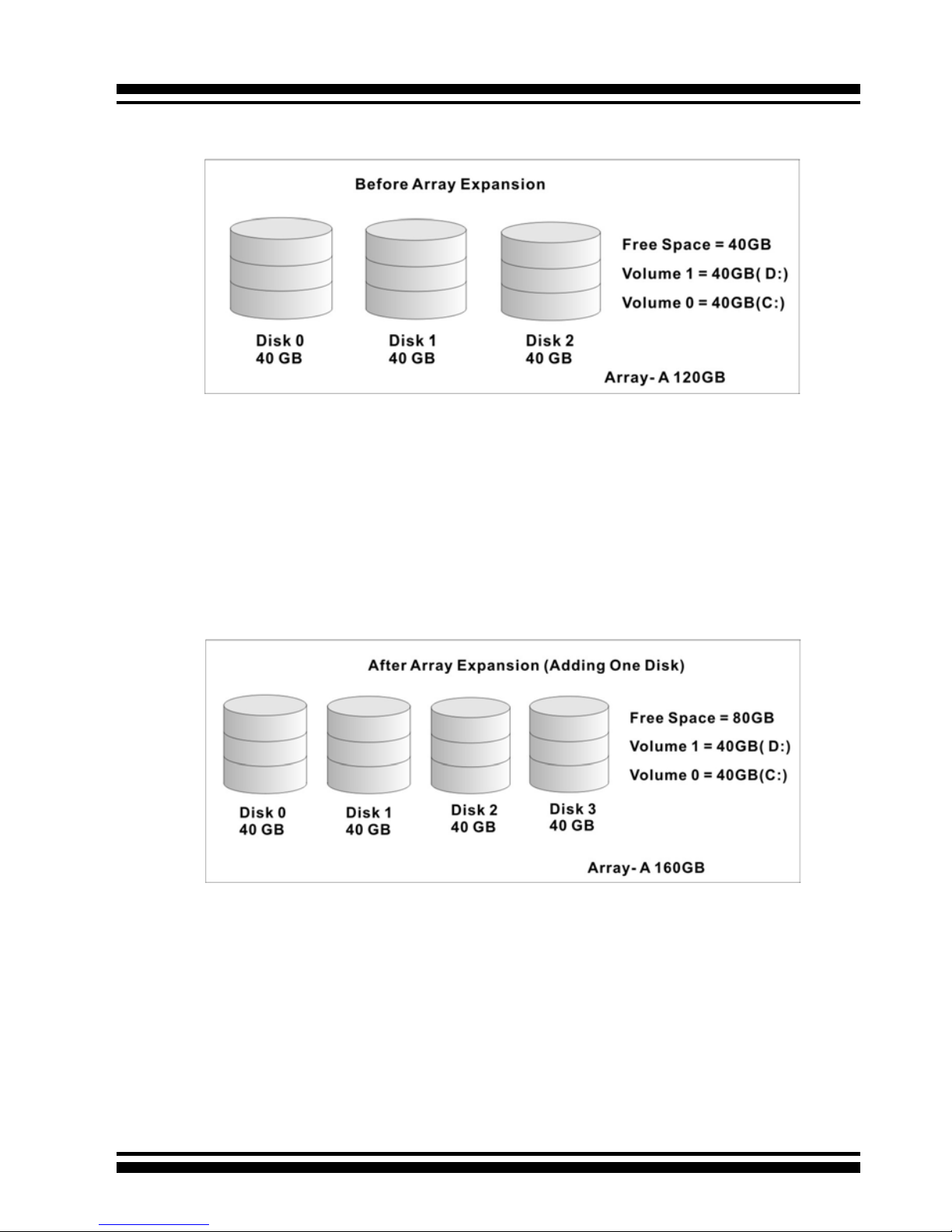
In the illustration, Volume 1 can be assigned a RAID 5 level of
operation while Volume 0 might be assigned a RAID 10 level of
operation. Alterantively, the Free Space can be used to create
Volume 2, which could then be set to use RAID Level 5.
1.3.3 Ease of Use Features
1.3.3.1 Instant Availability/Background Initialization
RAID 0 and RAID 1 volume sets can be used immediately after
creation because they do not create parity data. However, RAID
3, 5 and 6 volume sets must be initialized to generate parity
information. In Normal Initialization, the initialization proceeds
as a background task, and the volume set is fully accessible for
system reads and writes. The operating system can instantly
access the newly created arrays without requiring a reboot and
without waiting for initialization to complete. Furthermore, the
RAID volume set is protected against a single disk failure while
initialing. If using Fast Initialization, the initialization process
must be completed before the volume set is ready for system
accesses.
1.3.3.2 Array Roaming
The ARC-11xx/12xx RAID adapters store RAID conguration
information on the disk drives. The adapters therefor protect

INTRODUCTION
17
the conguration settings in the event of controller failure. Array
roaming allows the administrators the ability to move a completele raid set to another system without losing RAID conguration
information or data on that raid set. So, if a server fails, the raid
set disk drives can be moved to another server with an identical
RAID card and the disks can be inserted in any order.
1.3.3.3 Online Capacity Expansion
Online Capacity Expansion makes it possible to add one or more
physical drives to a volume set without interrupting server operation, eliminating the need to backup and restore after reconguration of the raid set. When disks are added to a raid set,
unused capacity is added to the end of the raid set. Then, data
on the existing volume sets (residing on the newly expanded
raid set) is redistributed evenly across all the disks. A contiguous block of unused capacity is made available on the raid set.
The unused capacity can be used to create additional volume
sets.
A disk, to be added to a Raid set, must be in normal mode (not
failed), free (not spare, in a raid set, or passed through to host)
and must have at least the same capacity as the smallest disk
capacity already in the Raid set.
Capacity expansion is only permitted to proceed if all volumes
on the Raid set are in the normal status. During the expansion
process, the volume sets being expanded can be accessed by
the host system. In addition, the volume sets with RAID levels
1, 1E, 3, 5 or 6 are protected against data loss in the event of
disk failure(s). In the case of disk failure, the volume set transitions from “migrating” state to “migrating+degraded“ state.
When the expansion is completed, the volume set would then
transition to “degraded” mode. If a global hot spare is present,
then it further transitions to the “rebuilding” state.
INTRODUCTION
18
The RAID subsystem controller redistributes the original volume
set over the original and newly added disks, using the same
fault-tolerance conguration. The unused capacity on the expand raid set can then be used to create an additional volume
set, with a different fault tolerance setting (if required by the
user.)
The RAID subsystem controller redistributes the original volume set over the original and newly added disks, using the
same fault-tolerance conguration. The unused capacity on the
expand raid set can then be used to create an additional volume sets, with a different fault tolerance setting if user need to
change.
The expansion process is illustrated as following gure.

INTRODUCTION
19
1.3.3.4 Online RAID Level and Stripe Size Migration
For those who wish to later upgrade to any RAID capabilities, a
system with Areca online RAID level/stripe size migration allows
a simplied upgrade to any supported RAID level without having
to reinstall the operating system.
ARC-11xx/12xx can migrate both the RAID level and stripe size
of an existing volume set, while the server is online and the
volume set is in use. Online RAID level/stripe size migration
can prove helpful during performance tuning activities as well
as when additional physical disks are added to the SATA RAID
controller. For example, in a system using two drives in RAID
level 1, it is possible to add a single drive and add capacity and
retain fault tolerance. (Normally, expanding a RAID level 1 array would require the addition of two disks). A third disk can be
added to the existing RAID logical drive and the array can then
be migrated from RAID level 1 to 5. The result would be parity
fault tolerance and double the available capacity without taking the system down. A forth disk could be added to migrate to
RAID level 6. It is only possible to migrate to a higher RAID level
by adding a disk; disks in an existing array can’t be recongured
for a higher RAID level without adding a disk.
Online migration is only permitted to begin If all volume to be
migrated are in the normal mode. During the migration process, the volume sets being migrated are accessed by the host
system. In addition, the volume sets with RAID levels 1, 1E,
3, 5 or 6 are protected against data loss in the event of disk
failure(s). In the case of disk failure, the volume set transitions
from migrating state to (migrating+degraded) state. When the
migration is completed, the volume set transitions to degraded
mode. If a global hot spare is present, then it further transitions
to rebuilding state.
1.3.3.5 Online Volume Expansion
Performing a volume expansion on the controller is the process
of growing only the size of the lastest volume. A more exible
option is for the array to concatenate an additional drive into the
RAID set and then expand the volumes on the y. This happens

INTRODUCTION
20
transparently while the volumes are online, but, at the end of
the process, the operating system will detect free space at after
the existing volume; the free space will not automatically be
incorporated into the existing operating system partition.
Windows, NetWare and other advanced operating systems support volume expansion, which enables you to incorporate the
additional free space within the volume into the operating system partition. The operating system partition is extended to
incorporate the free space so it can be used by the operating
system without creating a new operating system partition.
You can use the Diskpart.exe command line utility, included with
Windows Server 2003 or the Windows 2000 Resource Kit, to extend an existing partition into free space in the Dynamic disk.
Third-party software vendors have created utilities that can be
used to repartition disks without data loss. Most of these utilities
work ofine. Partition Magic is one such utility.
1.4 High availability
1.4.1 Global Hot Spares
A Global Hot Spare is an unused online available drive, which is
ready for replacing the failure disk. The Global Hot Spares is one
of the most important features that ARC-11xx/12xx RAID adapters provide to deliver a high degree of fault-tolerance. A global
Hot Spare is a spare physical drive that has been marked as a
global hot spare and therefore is not a member of any Raid set. If
a disk drive used in a RAID Volume Set fails, then the Global Hot
spare will automatically take its place and he data previously located on the failed drive is reconstructed on the Global Hot spare.
For this feature to work properly, the global hot spare must have
at least the same capacity as the drive it replaces. Global Hot
spares only work with RAID level 1, 1E, 3, 5, or 6 volume set. You
can congure up to three Global hot spares with ARC-11xx/12xx.
The Create Hot Spare option gives you the ability to dene a
INTRODUCTION
21
global hot spare disk drive. To effectively use the global hot
spare feature, you must always maintain at least one drive that
is marked as a global spare.
Important:
The hot spare must have at least the same capacity as the drive
it replaces.
1.4.2 Hot-Swap Disk Drive Support
The SATA RAID controller includes a protection circuit that supports the replacement of SATA hard disk drives without having
to shut down or reboot the system. A removable hard drive tray
can deliver “hot swappable” fault-tolerant RAID solutions at prices
much less than the cost of conventional SCSI hard disk SATA
RAID controllers. This feature provides advanced fault tolerant
RAID protection and “online” drive replacement.
1.4.3 Auto Declare Hot-Spare
If a disk drive is brought online into a system operating in degraded mode, ARC-11xx/12xx RAID adapters will automatically
declare the new disk as a spare and begin rebuilding the degraded volume. The Auto Declare Hot-Spare function requires that the
smallest drive contained within the volume set in which the failure
occurred.
In the normal status, the newly installed drive will be recongured
an online free disk. But, the newly-installed drive is automatically
assigned as a hot spare if any hot spare disk was used to rebuild
and without new installed drive replaced it. In this condition, the
Auto Declare Hot-Spare status will disappeared if the RAID subsystem has since powered off/on.
The Hot-Swap function can be used to rebuild disk drives in arrays
with data redundancy such as RAID level 1, 1E, 3, 5, and 6.

INTRODUCTION
22
1.4.4 Auto Rebuilding
If a hot spare is available, the rebuild starts automatically when
a drive fails. ARC-11xx/12xx RAID adapters automatically and
transparently rebuild failed drives in the background at user-denable rebuild rates.
If a hot spare is not available, the failed disk drive must be replaced with a new disk drive so that the data on the failed drive
can be automatically rebuilt and so that fault tolerance can be
maintained.
The ARC-11xx/12xx RAID adapters will automatically restart the
system and the rebuild process if the system is shut down or
powered off abnormally during a reconstruction procedure condition.
When a disk is Hot Swapped, although the system is functionally operational, the system may no longer be fault tolerant. Fault
tolerance will be lost until the removed drive is replaced and the
rebuild operation is completed.
During the automatic rebuild process, system activity will continue as normal, however, the system performance and fault tolerance will be affected.
1.4.5 Adjustable Rebuild Priority
Rebuilding a degraded volume incurs a load on the RAID subsystem. The ARC-11xx/12xx RAID adapters allow the user to select
the rebuild priority to balance volume access and rebuild tasks
appropriately. The Background Task Priority is a relative indication
of how much time the controller devotes to a background operation, such as rebuilding or migrating.
The RAID subsystem allows user to choose the task priority (Ultra
Low (5%), Low (20%), Medium (50%), High (80%)) to balance
volume set access and background tasks appropriately. For high
array performance, specify an Ultra Low value. Like volume initialization, after a volume rebuilds, it does not require a system
reboot.

INTRODUCTION
23
1.5 High Reliability
1.5.1 Hard Drive Failure Prediction
In an effort to help users avoid data loss, disk manufacturers are
now incorporating logic into their drives that acts as an "early
warning system" for pending drive problems. This system is called
SMART. The disk integrated controller works with multiple sensors
to monitor various aspects of the drive's performance, determines
from this information if the drive is behaving normally or not, and
makes available status information to RAID controller rmware
that probes the drive and look at it.
S.M.A.R.T. can often predict a problem before failure occurs.
Areca controllers will recognize a S.M.A.R.T. error code and notify
the administer of an impending hard drive failure.
1.5.2 Auto Reassign Sector
Under normal operation, even initially defect-free drive media can
develop defects. This is a common phenomenon. The bit density
and rotational speed of disks is increasing every year, and so is
the potential of problems. Usually a drive can internally remap
bad sectors without external help using cyclic redundancy check
(CRC) checksums stored at the end of each sector.
SATA drives perform automatic defect re-assignment for both
read and write errors. Writes are always completed - if a location
to be written is found to be defective, the drive will automatically
relocate that write command to a new location and map out the
defective location. If there is a recoverable read error, the correct data will be transferred to the host and that location will be
tested by the drive to be certain the location is not defective. If
it is found to have a defect, data will be automatically relocated,
and the defective location is mapped out to prevent future write
attempts.
In the event of an unrecoverable read error, the error will be
reported to the host and the location agged as potentially defective. A subsequent write to that location will initiate a sector test
and relocation should that location have a defect. Auto Reassign

INTRODUCTION
24
Sector does not affect disk subsystem performance because it
runs as a background task. Auto Reassign Sector discontinues
when the operating system makes a request.
1.5.3 Consistency Check
A consistency check is a process that veries the integrity of
redundant data. For example, performing a consistency check
of a mirrored drive assures that the data on both drives of the
mirrored pair is exactly the same. To verify RAID 3, 5 or 6 redundancy, a consistency check reads all associated data blocks, computes parity, reads parity, and veries that the computed parity
matches the read parity.
Consistency checks are very important because they detect and
correct parity errors or bad disk blocks in the drive. A consistency
check forces every block on a volume to be read, and any bad
blocks are marked; those blocks are not used again. This is critical and important because a bad disk block can prevent a disk
rebuild from completing. We strongly recommend that you run
consistency checks on a regular basis—at least once per week.
Note that consistency checks degrade performance, so you should
run them when the system load can tolerate it.
1.6 Data Protection
1.6.1 BATTERY BACKUP
Areca controllers are armed with a Battery Backup Module (BBM).
While a Uninterruptible Power Supply (UPS) protects most servers
from power uctuations or failures, a BBM provides an additional
level of protection. In the event of a power failure, a BBM supplies
power to retain data in the RAID controller’s cache, thereby permitting any potentially dirty data in the cache to be ushed out to
secondary storage when power is restored.
The batteries in the BBM are recharged continuously through a
trickle-charging process whenever the system power is on. The
batteries protect data in a failed server for up to three or four
days, depending on the size of the memory module. Under normal operating conditions, the batteries last for three years before

INTRODUCTION
25
replacement is necessary.
1.6.2 RECOVERY ROM
The RAID subsystem rmware is stored on the controller ash
ROM and is executed by the I/O processor. The rmware can also
be updated through the PCI-X/PCIe bus port or Ethernet port (if
equipped) without the need to replace any hardware chips. During the controller rmware upgrade ash process, it is possible for
a problem to occur resulting in corruption of the controller rmware. With our Redundant Flash image feature, the controller will
revert back to the last known version of rmware and continue
operating. This reduces the risk of system failure due to rmware
crash.
1.7 Understanding RAID
RAID is an acronym for Redundant Array of Independent Disks. It
is an array of multiple independent hard disk drives that provides
high performance and fault tolerance. The SATA RAID controller implements several levels of the Berkeley RAID technology.
An appropriate RAID level is selected when the volume sets are
dened or created. This decision should be based on the desired
disk capacity, data availability (fault tolerance or redundancy),
and disk performance. The following section discusses the RAID
levels supported by the SATA RAID controller.
The SATA RAID controller makes the RAID implementation and
the disks’ physical conguration transparent to the host operating stem. This means that the host operating system drivers and
software utilities are not affected, regardless of the RAID level
selected. Correct installation of the disk array and the controller requires a proper understanding of RAID technology and the
concepts.
1.7.1 RAID 0
RAID 0, also referred to as striping, writes stripes of data across
multiple disk drives instead of just one disk drive. RAID 0 does
not provide any data redundancy, but does offer the best high-

INTRODUCTION
26
speed data throughput. RAID 0 breaks up data into smaller blocks
and then writes a block to each drive in the array. Disk striping enhances performance because multiple drives are accessed
simultaneously; the reliability of RAID Level 0 is less because the
entire array will fail if any one disk drive fails, due to a lack of
redundancy.
1.7.2 RAID 1
RAID 1 is also known as “disk mirroring”; data written to one disk
drive is simultaneously written to another disk drive. Read performance may be enhanced if the array controller can, in parallel,
accesses both members of a mirrored pair. During writes, there
will be a minor performance penalty when compared to writing
to a single disk. If one drive fails, all data (and software applications) are preserved on the other drive. RAID 1 offers extremely
high data reliability, but at the cost of doubling the required data
storage capacity.
INTRODUCTION
27
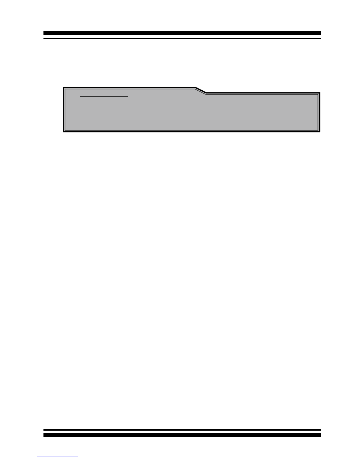
1.7.3 RAID 1E
RAID 1E is a combination of RAID 0 and RAID 1, combing stripping with disk mirroring. RAID Level 10 combines the fast performance of Level 0 with the data redundancy of Leve1 1. In
this conguration, data is distributed across several disk drives,
similar to Level 0, which are then duplicated to another set of
drive for data protection. RAID 1E has been traditionally implemented using an even number of disks, some hybrids can use an
odd number of disks as well. Illustration is an example of a hybrid RAID 1E array comprised of ve disks; A, B, C, D and E. In
this conguration, each strip is mirrored on an adjacent disk with
wrap-around. In fact this scheme - or a slightly modied version
of it - is often referred to as RAID 1E and was originally proposed
by IBM. When the number of disks comprising a RAID 1E is even,
the striping pattern is identical to that of a traditional RAID 1E,
with each disk being mirrored by exactly one other unique disk.
Therefore, all the characteristics for a traditional RAID 1E apply
to a RAID 1E when the latter has an even number of disks. Areca
RAID 1E offers a little more exibility in choosing the number of
disks that can be used to constitute an array. The number can be
even or odd.
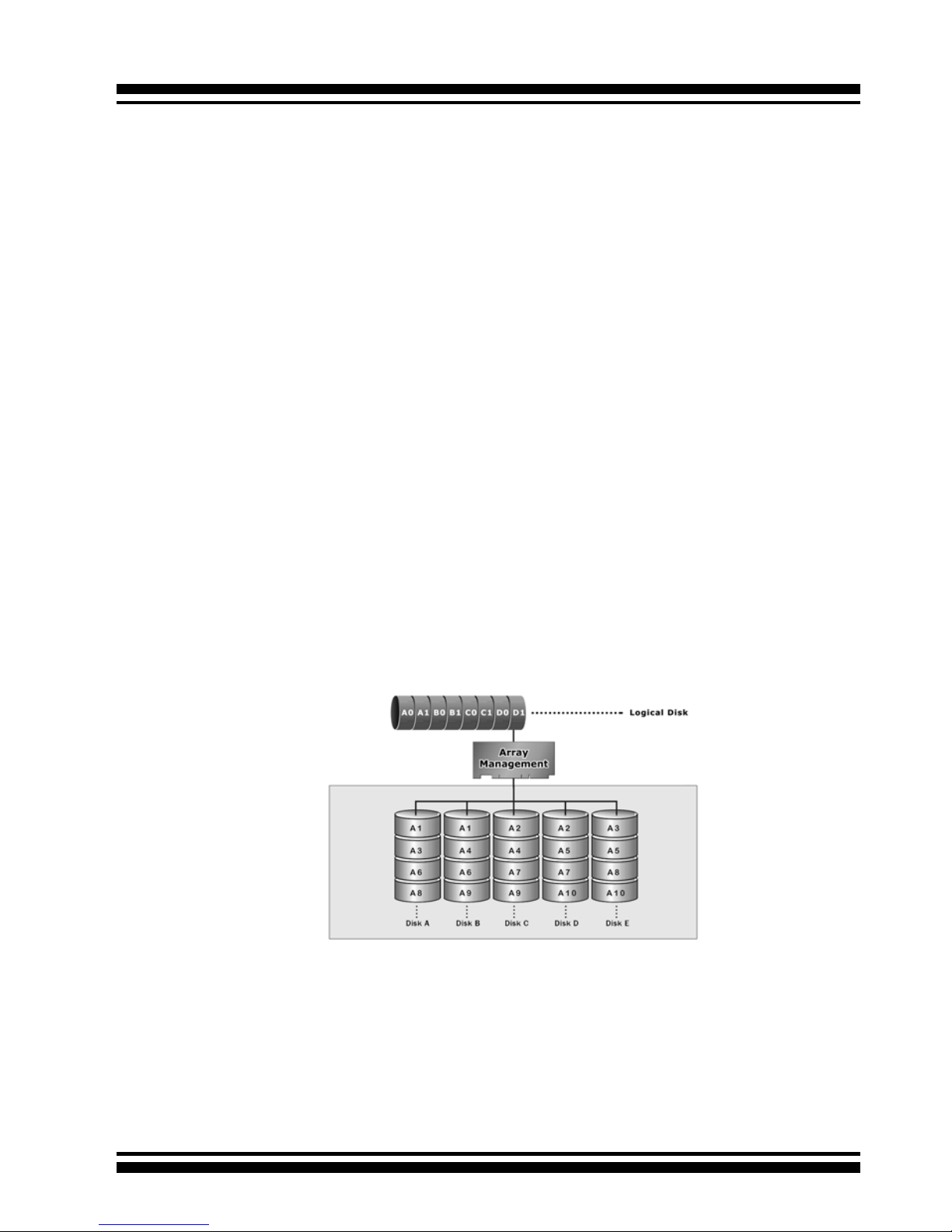
1.7.4 RAID 3
RAID 3 provides disk striping and complete data redundancy
though a dedicated parity drive. RAID 3 breaks up data into
smaller blocks, calculates parity by performing an exclusive-or
on the blocks, and then writes the blocks to all but one drive in
INTRODUCTION
28
1.7.5 RAID 5
RAID 5 is sometimes called striping with parity at byte level. In
RAID 5, the parity information is written to all of the drives in the
controllers rather than being concentrated on a dedicated parity
disk. If one drive in the system fails, the parity information can
be used to reconstruct the data from that drive. All drives in the
array system can be used for seek operations at the same time,
greatly increasing the performance of the RAID system. This
relieves the write bottleneck that characterizes RAID 4, and is the
primary reason that RAID 5 is more often implemented in RAID
arrays.
the array. The parity data created during the exclusive-or is then
written to the last drive in the array. If a single drive fails, data is
still available by computing the exclusive-or of the contents corresponding strips of the surviving member disk. RAID 3 is best
for applications that require very fast data- transfer rates or long
data blocks.
INTRODUCTION
29
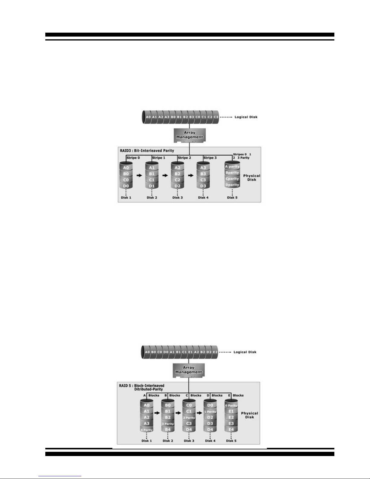
1.7.6 RAID 6
RAID 6 provides the highest reliability, but is not yet widely used.
It is similar to RAID 5, but it performs two different parity computations or the same computation on overlapping subsets of
the data. RAID 6 can offer fault tolerance greater than RAID 1 or
RAID 5 but only consumes the capacity of 2 disk drives for distributed parity data. RAID 6 is an extension of RAID 5 but uses a
second, independent distributed parity scheme. Data is striped on
a block level across a set of drives, and then a second set of parity is calculated and written across all of the drives.
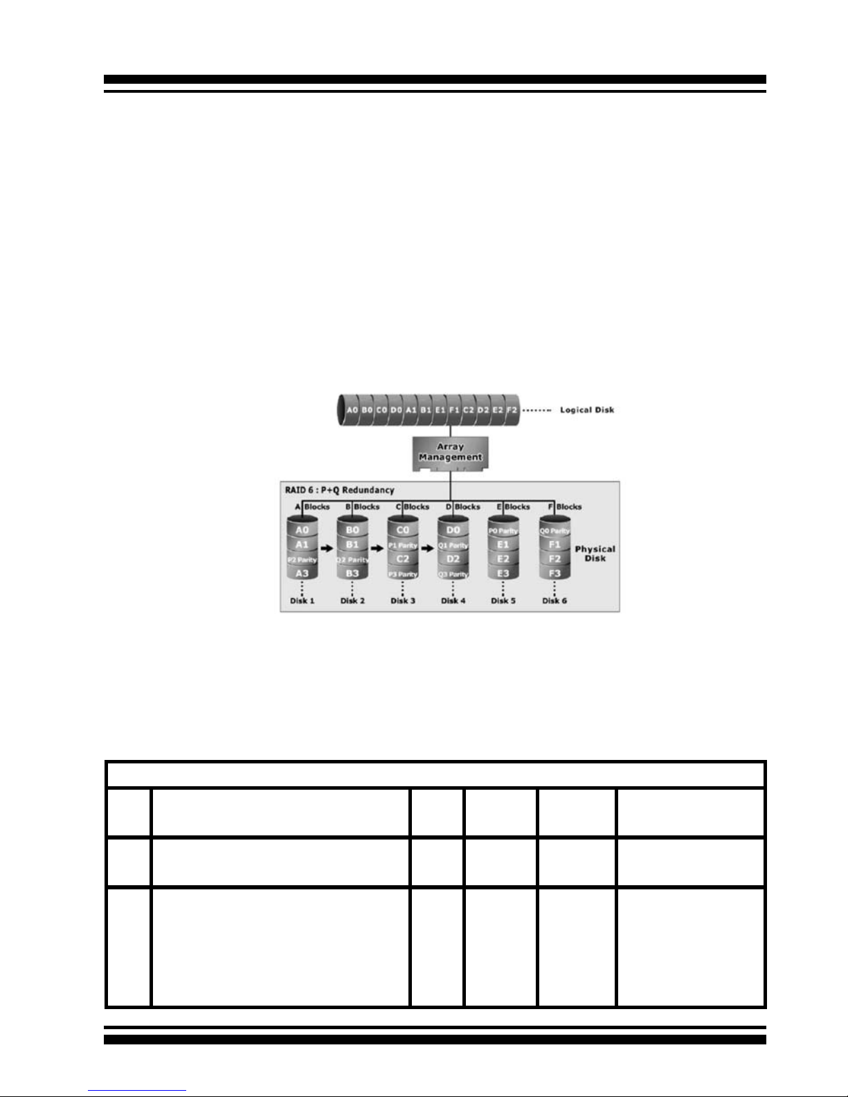
Summary of RAID Levels
The SATA RAID controller supports RAID Levels 0, 1, 1E, 3, 5 and 6.
The table below provides a summary of RAID levels.
Features and Performance
RAID
Level
Description Min.
Drives
Data
Reliability
Data
Transfer
Rate
I/O Request
Rates
0 Also known as stripping
Data distributed across multiple drives in
the array. There is no data protection.
1 No data
Protection
Very High Very High for
Both Reads and Writes
1 Also known as mirroring
All data replicated on N separated disks.
N is almost always 2.
This is a high availability solution, but due
to the 100% duplication, it is also a costly
solution. Half of drive capacity in array
devoted to mirroring.
2 Lower
than RAID
6;
Higher
than
RAID 3, 5
Reads are
higher
than a
single disk;
Writes
similar to a
single disk
Reads are twice as fast
as a single disk;
Write are similar to a
single disk.
INTRODUCTION
30
1E Also known Block-Interleaved Parity.
Data and parity information is subdivided
and distributed across all disks. Parity must
be the equal to the smallest disk capacity
in the array. Parity information normally
stored on a dedicated parity disk.
3 Lower
than RAID
6;
Higher
than
RAID 3, 5
Transfer
rates more
similar
to RAID
1 than
RAID 0
Reads are twice as fast
as a single disk;
Writes are similar to a
single disk.
3 Also known Bit-Interleaved Parity.
Data and parity information is subdivided
and distributed across all disks. Parity data
consumes the capacity of 1 disk drive.
Parity information normally stored on a
dedicated parity disk.
3 Lower
than RAID
1, 1E, 6;
Higher
than a
single
drive
Reads are
similar to
RAID 0;
Writes are
slower
than a
single disk
Reads are close to being twice as fast as a
single disk;
Writes are similar to a
single disk.
5 Also known Block-Interleaved Distributed
Parity.
Data and parity information is subdivided
and distributed across all disk. Parity data
consumes the capacity of 2 disk drive.
3 Lower
than RAID
1, 1E, 6;
Higher
than a
single
drive
Reads are
similar to
RAID 0;
Writes are
slower
than a
single disk
Reads are similar to
RAID 0;
Writes are slower than
a single disk.
6 RAID 6 provides the highest reliability. Sim-
ilar to RAID 5, but does two different parity
computations. RAID 6 offers fault tolerance
greater that RAID 1 or RAID 5. Parity data
consumes the capacity of 2 disk drives.
4 highest
reliability
Reads are
similar to
RAID 0;
Writes are
slower
than a
single disk
Reads are similar to
RAID 0;
Writes are slower than
a single disk.

HARDWARE INSTALLATION
31
2. Hardware Installation
This section describes the procedures for installing the ARC-11xx/12xx
series controllers.
2.1 Before Your begin Installation
Thanks for purchasing the SATA RAID Controller as your RAID data
storage and management system. This user guide gives simple
step-by-step instructions for installing and conguring the SATA
RAID Controller. To ensure personal safety and to protect your
equipment and data, carefully read the information following the
package content list before you begin installing.
Package Contents
If your package is missing any of the items listed below, contact
your local dealer before proceeding with installation (disk drives
and disk mounting brackets are not included):
ARC-11xx Series SATA RAID Controller
• 1 x PCI-X SATA RAID Controller in an ESD-protective bag
• 4/8/12/16/24 x SATA interface cables (one per port)
• 1 x Installation CD
• 1 x User Manual
ARC-11xxML/12xxML Series SATA RAID Controller
• 1 x PCI-X SATA RAID Controller in an ESD-protective bag
• 1 x Installation CD
• 1 x User Manual
ARC-12xx Series SATA RAID Controller
• 1 x PCI-Express SATA RAID Controller in an ESD-protective bag
• 4/8/12/16/24 x SATA interface cables (one per port)
• 1 x Installation CD
• 1 x User Manual

HARDWARE INSTALLATION
32
2.2 Board Layout
Follow the instructions below to install a PCI RAID Card into your
PC / Server.
Figure 2-1, ARC-1110/1120 (4/8-port PCI-X SATA RAID Controller)
Figure 2-2, ARC-1210/1220 (4/8-port PCI-Express SATA RAID Controller)

HARDWARE INSTALLATION
33
Figure 2-3, ARC-1110ML/1120ML (4/8-port PCI-X SATA RAID Controller)
Figure 2-4, ARC-1130/1160 (12/16-port PCI-X SATA RAID Controller)

HARDWARE INSTALLATION
34
Figure 2-5, ARC-1130ML/1160ML (12/16-port PCI-X SATA RAID
Controller)
Figure 2-6, ARC-1230/1260 (12/16-port PCI-EXpress SATA RAID
Controller)

HARDWARE INSTALLATION
35
Figure 2-7, ARC-1170 (24-port PCI-X SATA RAID Controller)
Figure 2-8, ARC-1280 (24-port PCI-Express SATA RAID Controller)

HARDWARE INSTALLATION
36
Tools Required
An ESD grounding strap or mat is required. Also required are standard hand tools to open your system’s case.
System Requirement
The controller can be installed in a universal PCI slot and requires
a motherboard that:
ARC-11xx series required one of the following:
• Complies with the PCI Revision 2.3 32/64-bit 33/66MHz, 3.3V.
• Complies with the PCI-X 32/64-bit 66/100/133 MHz, 3.3V.
ARC-12xx series requires:
• Complies with the PCI-Express X8
The SATA RAID controller may be connected to up to 4, 8, 12, 16,
or 24 SATA ll hard drives using the supplied cables.
Optional cables are required to connect any drive activity LEDs and
fault LEDs on the enclosure to the PCI SATA RAID controller.
Installation Tools
The following items may be needed to assist with installing the
Figure 2-9, ARC-1230ML/1260ML/1280ML (12/16/24-port PCI-Express SATA RAID Controller)

HARDWARE INSTALLATION
37
SATA RAID adapter into an available PCI expansion slot.
• Small screwdriver
• Host system hardware manuals and manuals for the disk or
enclosure being installed.
Personal Safety Information
To ensure personal safety as well as the safety of the equipment:
• Always wear a grounding strap or work on an ESD-protective
mat.
• Before opening the system cabinet, turn off power switches and
unplug the power cords. Do not reconnect the power cords until
you have replaced the covers.
Warning:
High voltages may be found inside computer equipment. Before
installing any of the hardware in this package or removing the
protective covers of any computer equipment, turn off power
switches and disconnect power cords. Do not reconnect the power
cords until you have replaced the covers.
Electrostatic Discharge
Static electricity can cause serious damage to the electronic components on this SATA RAID adapter. To avoid damage caused by
electrostatic discharge, observe the following precautions:
• Don’t remove the SATA RAID controller from its anti-static packaging until you are ready to install it into a computer case.
• Handle the SATA RAID Controller by its edges or by the metal
mounting brackets at its each end.
• Before you handle the SATA RAID controller in any way, touch a
grounded, anti-static surface, such as an unpainted portion of the
system chassis, for a few seconds to discharge any built-up static
electricity.
2.3 Installation
Follow the instructions below to install a PCI RAID Card into your
PC / Server.

HARDWARE INSTALLATION
38
Step 1. Unpack
Unpack and remove the PCI RAID card from the package. Inspect
it carefully, if anything is missing or damaged, contact your local
dealer.
Step 2. Power PC/Server Off
Turn off computer and remove the AC power cord. Remove the
system’s cover. See the computer system documentation for instruction.
Step 3. Install the PCI RAID Cards
To install the SATA RAID adapter, remove the mounting screw and
existing bracket from the rear panel behind the selected PCI slot.
Align the gold-ngered edge on the card with the selected PCI expansion slot. Press down gently but rmly to ensure that the card
is properly seated in the slot, as shown in Figure 2-10. Next, screw
the bracket into the computer chassis. 11xx cards can t in both
PCI (32-bit/3.3V) and PCI-X slots. It can get the best performance
installed in a 64-bit/133MHz PCI-X slot. 12xx cards require a PCIExpress 8X slot.
Figure 2-10, Insert PCI RAID Card into a PCI slot

HARDWARE INSTALLATION
39
Step 5 Connect the SATA cable
Model ARC-11XX and ARC-12XX cards have dual-layer SATA internal connectors. If you have not already connected your SATA
cables, use the cables included with your kit to connect the controller to the SATA hard drives.
The cable connectors are all identical, so it does not matter which
end you connect to your controller, SATA hard drive, or cage backplane SATA connector.
Figure 2-12, SATA Cable
Figure 2-11, Mount Cages & Drives
Step 4. Mount the Cages or Drives
Remove the front bezel from the computer chassis and install the
Cages or SATA Drives in the computer chassis. Loading drives to
the drive tray if cages are installed. Be sure that the power is connected to either the Cage backplane or the individual drives.
Note:
The SATA cable connectors must match your HDD cage.
For example: Channel 1 of RAID Card connects to channel 1
of HDD cage, channel 2 of RAID Card connects to channel 2 of
HDD cage, and follow this rule.

HARDWARE INSTALLATION
40
Step 5-3. Connect the Min SAS 4i to 4*SATA cable
Model ARC-1230ML/1260ML/1280ML have Min SAS 4i (SFF-8087)
internal connectors, each of them can support up to four SATA
drives. These adapters can be installed in a server RAID enclosure
with a standard SATA connector backplane. Min SAS 4i to SATA
cables are included in the ARC-1230ML/1260ML/1280ML package.
The following diagram shows the picture of MinSAS 4i to 4*SATA
cables.
Unpack and remove the PCI RAID cards. Inspect it carefully. If
anything is missing or damaged, contact your local dealer.
Figure 2-13, Multi-Lance Cable
Step 5-2. Connect the Multi-lance cable
Model ARC-11XXML has multi-lance internal connectors, each of
them can support up to four SATA drives. These adapters can be
installed in a server RAID enclosure with a Multi-lance connector
(SFF-8470) backplane. Multi-lance cables are not included in the
ARC-11XXML package.
If you have not already connected your Multi-lance cables, use the
cables included with your enclosure to connect your controller to
the Multi-lance connector backplane. The type of cable will depend
on what enclosure you have. The following diagram shows the picture of Multi-lane cable.
Unpack and remove the PCI RAID cards. Inspect it carefully. If anything is missing or damaged, contact your local dealer.

HARDWARE INSTALLATION
41
Figure 2-14, Min SAS 4i to 4*SATA
Step 5-4. Connect the Min SAS 4i to Multi-lance cable
Model ARC-1230ML/1260ML/1280ML have Min SAS 4i internal
connectors, each of them can support up to four SATA drives. These
adapters can be installed in a server RAID enclosure with a Multilance connector (SFF-8470) backplane. Multi-lance cables are not
included in the ARC-12XXML package.
If you have not already connected your Min SAS 4i to Multilance cables, buy the Min SAS 4i to Multi-lance cables to t your
enclosure. And connect your controller to the Multi-lance connector
backplane. The type of cable will depend on what enclosure you
have. The following diagram shows the picture of Min SAS 4i to
Multi-lance cable.
Unpack and remove the PCI RAID cards. Inspect it carefully. If
anything is missing or damaged, contact your local dealer.
Figure 2-15, Min SAS 4i to Multi-lance

HARDWARE INSTALLATION
42
Step 6 Install the LED cable (optional)
ARC-1XXX Series Fault/Activity Header Intelligent Electronics
Schematic
The intelligent LED controller outputs a low-level pulse to determine if status LEDs are attached to pin sets 1 and 2. This allows
automatic controller conguration of the LED output. If the logical
level is different between the st 2 sets of the HDD LED header
(LED attached to Set 1 but not Set 2), the controller will assign the
rst HDD LED header as the global indicator connector. Otherwise,
each LED output will show only individual drive status.
The SATA RAID controller provides three kinds of LED status connectors.
A: Global indicator connector, which lights when any drive is active.
B: Individual LED indicator connector, for each drive channel.
C: I2C connector, for SATA proprietary backplane enclosure.
D: SGPIO connector for SAS Backplane enclosure
The following diagrams and description describes each type of connector.

HARDWARE INSTALLATION
43
Note:
A cable for the global indicator comes with your computer system. Cables for the individual drive LEDs may come with a drive
cage, or you may need to purchase them.
Figure 2-16, ARC1110/1120/1210/1220
global LED connection
for Computer Case.
Figure 2-17, ARC1130/1160/1230/1260
global LED connection
for Computer Case.
A: Global Indicator Connector
If the system will use only a single global activity indicator, attach
the LED to the rst two pins of the connector. The following diagrams show the connector and pin locations.

HARDWARE INSTALLATION
44
Figure 2-20, ARC-1230ML/
1260ML/1280ML global LED
connection for Computer
Case.
Figure 2-19, ARC-1280
global LED connection for
Computer Case.
Figure 2-18, ARC-1170
global LED connection
for Computer Case.

HARDWARE INSTALLATION
45
LED Normal Status Problem Indication
Disk Activity When the activity LED is illu-
minated, there is I/O activity
on that disk drive. When the
LED is dark, there is no activity on that disk drive.
N/A
Fault LED When the fault LED is solid
illuminated, there is no disk
present.
When the Red LED is slow blinking
(2 times/sec), that disk drive has
failed and should be hot-swapped
immediately. When the Blue LED
is illuminated and Red LED is fast
blinking (10 times/sec) there is rebuilding activity on that disk drive.
B: Individual LED indicator connector
Connect the cables for the drive activity LEDs and fault LEDs between the backplane of the cage and the respective connector on
the SATA RAID controller. The following describes the fault/activity LED.
Figure 2-21, ARC1110/1120/1210/1220
Individual LED indicators connector, for each
channel drive.
Figure 2-22, ARC1130/1160/1230/1260
Individual LED indicators connector, for each
channel drive.

HARDWARE INSTALLATION
46
Figure 2-23, ARC-1170
Individual LED indicators
connector, for each channel drive.
Figure 2-24, ARC-1280
Individual LED indicators
connector, for each channel drive.
Figure 2-25, ARC-1230ML/
1260ML/1280ML Individual
LED indicators connector, for
each channel drive.

HARDWARE INSTALLATION
47
C: I2C Connector
You can also connect the I2C interface to a proprietary SATA
backplane enclosure. This can reduce the number of activity LED
and/or fault LED cables. The I2C interface can also cascade to another SATA backplane enclosure for the additional channel status
display.
Figure 2-26, Activity/Fault LED I2C connector connected between
SATA RAID Controller & SATA HDD Cage backplane.
Figure 2-27, Activity/Fault LED I2C connector connected between
SATA RAID Controller & 4 SATA HDD backplane.
Note:
Ci-Design has supported this feature in its 4-port 12-6336-05A
SATA ll backplane.

HARDWARE INSTALLATION
48
PIN Description PIN Description
1 power (+5V) 2 GND
3 LCD Module Interrupt 4 Fault/Activity Interrupt
5 LCD Module Serial Data 6 Fault/Activity clock
7 Fault/Activity Serial Data 8 LCD Module clock
The following is the I2C signal name description for LCD & Fault/Activity LED.
D: SGPIO Connector
The preferred I/O connector for server backplanes is the Min SAS
4i internal serial-attachment connector. This connector has eight
signal pins to support four SATA drives and six pins for the SGPIO
(Serial General Purpose Input/Output) side-band signals. The
SGPIO bus is used for efcient LED management and for sensing drive Locate status. See SFF 8485 for the specication of the
SGPIO bus.
The number of drives supported can be increased, by a factor of
four, by adding similar backplane to maximum of 24 drives (6
backplanes)
LED Management: The backplane may contain LEDs to indicate
drive status. Light from the LEDs could be transmitted to the outside of the server by using light pipes mounted on the SAS drive
tray. A small microcontroller on the backplane, connected via the
SGPIO bus to a ARC-1230ML/1260ML/1280ML SATA RAID controller, could control the LEDs. Activity: blinking 5 Times/Second
Fault: solid illuminated
Drive Locate Circuitry: The locate of a drive may be detected by
sensing the voltage level of one of the pre-charge pins before and

HARDWARE INSTALLATION
49
after a drive is installed. Fault (red) blinking 2 Times/Second.
The following signal denes the SGPIO assignments for the Min
SAS 4i connector in ARC-1230ML/1260ML/1280ML.
Step 7. Re-check the SATA HDD LED and Fault LED Cable
connections
Be sure that the proper failed drive channel information is displayed by the Fault and HDD Activity LEDs. An improper connection will will tell the user to ‘‘Hot Swap’’ the wrong drive. This can
result in removing the wrong disk (one that is functioning properly)
from the controller. This can result in failure and loss of system
data.
Step 8. Power up the System
Thoroughly check the installation, reinstall the computer cover, and
reconnect the power cord cables. Turn on the power switch at the
rear of the computer (if equipped) and then press the power button
at the front of the host computer.
Step 9. Congure volume set
The adapter congures RAID functionality through the McBIOS
RAID manager. Please reference Chapter 3, McBIOS RAID Man-
ager, for the detail regarding conguration. The RAID controller
can also be congured through the McRAID storage manager software utility after ArcHttp proxy server is installed. For this option,
please reference Chapter 6, Web Browser-Based Conguration.
Step 10. Install the controller driver
For a new system:
PIN Description PIN Description
SideBand0 SClock (Clock Signal) SideBand1 SLoad (Last clock of a bit
stream)
SideBand2 Ground SideBand3 Ground
SideBand4 SDataOut (Serial data
output bit stream)
SideBand5 SDataIn (Serial data input bit
stream)

HARDWARE INSTALLATION
50
• Driver installation usually takes places as part of operating system
installation. Please reference the Chapter 4 Diver Installation for the
detail installation procedure.
In an existing system:
• Install the controller driver into the existing operating system.
Please reference the Chapter 4, Driver Installation, for the detailed
installation procedure.
Step 11. Install ArcHttp proxy Server
The SATA RAID controller rmware has embedded the web-browser
RAID manager. ArcHttp Proxy driver will enable it. The Browserbased RAID manager provides all of the creation, management,
and monitor SATA RAID controller status. Please reference the
Chapter 5 for the detail ArcHtt proxy server installation. For SNMP
agent function, please reference Appendix C.
Step 12. Determining the Boot sequences
The SATA RAID controller is a bootable controller. If your system
already contains a bootable device with an installed operating system, you can set up your system to boot a second operating system from the new controller. To add a second bootable controller,
you may need to enter Setup and change the device boot sequence
so that the SATA RAID controller heads the list. If the system BIOS
Setup does not allow this change, your system may not be congurable to allow the SATA RAID controller to act as a second boot
device.
Summary of the installation
The ow chart below describes the installation procedures for SATA
Note:
Look for newest release versions of drivers for Linux and FreeBSD:
• See the Driver Library at http://www.areca.com.tw

HARDWARE INSTALLATION
51
Conguration Utility Operating System supported
McBIOS RAID Manager OS-Independent
McRAID Storage Manager
(Via Archttp proxy server)
Windows 2000/XP/2003, Linux, FreeBSD, NetWare, Unixware, Solaris and Mac
SAP Monitor (Single Admin portal to
scan for multiple RAID units in the network, Via ArcHttp Proxy Server)
Windows 2000/XP/2003
SNMP Manager Console Integration Windows 2000/XP/2003, Linux
FreeBSD
RAID controller. These procedures included hardware installation, the creation and conguration of a RAID volume through the
McBIOS, OS installation and installation of SATA RAID controller
software.
The software components congure and monitor the SATA RAID
controller via ArcHttp Proxy Server.
McRAID Storage Manager
Before launching the Firmware-embedded web server, McRAID
Storage manager, you need rst to install the ArcHttp Proxy Server
on your server system. If you need additional information about
installation and start-up of this function, see the McRAID Storage
Manager section in Chapter 6.
SNMP Manager Console Integration
• Out of Band-Using Ethernet port (12/16/24-port Adapter)
Before launching the Firmware-embedded SNMP agent in the

HARDWARE INSTALLATION
52
sever, you need rst to enable the Fireware-embedded SNMP
agent function and install the SNMP extension agent software
on your server system. If you need additional information about
installation and start-up this function, see the section 6.9.4 SNMP
Conguration (12/16/24-port)
• In-Band-Using PCI-X/PCIe Bus (4/8/12/16/24-port
Adapter)
Before launching the SNMP agent in the sever, you need rst to
enable the reware-embedded SNMP community conguration
and install Areca SNMP extension agent in your server system.
If you need additional information about installation and start-up
the function, see the SNMP operation & Installation section in the
Appendix C
Single Admin Portal (SAP) Monitor
This utility can scan for multiple RAID units on the network and
monitor the controller set status. It also includes a disk stress test
utility to identify marginal spec disks before the RAID unit is put
into a production environment.
For additional information, see the Utility manual in the packaged
CD-ROM or download it from the web site http://www.areca.
com.tw.

BIOS CONFIGURATION
53
3. McBIOS RAID Manager
The system mainboard BIOS automatically congures the following
SATA RAID controller parameters at power-up:
• I/O Port Address
• Interrupt channel (IRQ)
• Adapter ROM Base Address
Use McBIOS to further congure the SATA RAID adapter to suit your
server hardware and operating system.
3.1 Starting the McBIOS RAID Manager
This section explains how to use the McBIOS Setup Utility to congure your RAID system. The BIOS Setup Utility is designed to be
user-friendly. It is a menu-driven program, residing in the rmware, which allows you to scroll through various menus and submenus and select among the predetermined conguration options.
When starting a system with an SATA RAID controller installed, it
will display the following message on the monitor during the startup sequence (after the system bios startup screen but before the
operating system boots):
The McBIOS conguration manager message remains on your
screen for about nine seconds, giving you time to start the congure menu by pressing Tab or F6. If you do not wish to enter conguration menu, press <ESC> to skip conguration immediately.
When activated, the McBIOS window appears showing a selection
dialog box listing the SATA RAID controllers that are installed in the
system.
The legend at the bottom of the screen shows you what keys are
enabled for the windows.
I/O-Port=F3000000h, IRQ=11, BIOS ROM mapped at D000:0h
No BIOS disk Found, RAID Controller BIOS not installed!
Press <Tab/F6> to enter SETUP menu. 9 second(s) left <ESC to Skip>..
ARC-1xxx RAID Ctrl - DRAM: 128(MB) / #Channels: 8
BIOS: V1.00 / Date: 2004-5-13 - F/W: V1.31 / Date: 2004-5-31

BIOS CONFIGURATION
54
Areca Technology Corporation RAID Controller Setup <V1.0, 2004/05/20>
ArrowKey Or AZ:Move Cursor, Enter: Select, ** Select & Press F10 to Reboot**
Select An Adapter To Congure
( 3/14/ 0)I/O=DD200000h, IRQ = 9
Use the Up and Down arrow keys to select the adapter you want
to congure. While the desired adapter is highlighted, press the
<Enter> key to enter the Main Menu of the McBIOS Conguration
Utility.
3.2 McBIOS Conguration manager
The McBIOS conguration utility is rmware-based and is used to
congure raid sets and volume sets. Because the utility resides in
the SATA RAID controller rmware, operation is independent of any
operating systems on your computer. This utility can be used to:
• Create raid sets,
• Expand raid sets,
Controller I/O Port:F3000000h, F2: Select Controller, F10: Reboot System
ArrowKey Or AZ:Move Cursor, Enter: Select, ESC: Escape, L:Line Draw, X: Redraw
Areca Technology Corporation RAID Controller
Main Menu
Raid Set Function
Volume Set Function
Physical Drives
Raid System Function
Ethernet Conguration
View System Events
Clear Event Buffer
Hardware Monitor
System information
Quick Volume/Raid Setup
Verify Password
Note:
T h e m a n u f a c t u r e
default password is
se t t o 00 0 0; thi s
p a s s w o r d c a n b e
modied by selecting
Change Password
in the Raid System
Function section.

BIOS CONFIGURATION
55
3.4 Designating Drives as Hot Spares
Any unused disk drive that is not part of a RAID Set can be designated as a Hot Spare. The Quick Volume/Raid Setup conguration will add the spare disk drive and automatically display the
appropriate raid level from which the user can select. For the Raid
Set Function conguration option, the user can use the Create Hot
Spare option to dene the hot spare disk drive.
When a Hot Spare disk drive is being created using the Create Hot
Spare option (in the Raid Set Function), all unused physical devices
connected to the current controller appear:
Choose the target disk by selecting the appropriate check box.
Press the Enter key to select a disk drive, and press Yes in the
Create Hot Spare to designate it as a hot spare.
• Add physical drives,
• Dene volume sets,
• Modify volume sets,
• Modify RAID level/stripe size,
• Dene pass-through disk drives,
• Modify system functions, and
• Designate drives as hot spares.
3.3 Conguring Raid Sets and Volume Sets
You can congure RAID sets and volume sets with McBIOS RAID
manager automatically using Quick Volume/Raid Setup or manually
using Raid Set/Volume Set Function. Each conguration method requires a different level of user input. The general ow of operations
for RAID Set and Volume Set conguration is:
Step Action
1 Designate hot spares/pass-through drives (optional).
2 Choose a conguration method.
3 Create RAID sets using the available physical drives.
4 Dene Volume Sets using the space available in the RAID Set.
5 Initialize the Volume Sets and use Volume Sets (as logical drives) in the
host OS.

BIOS CONFIGURATION
56
3.5 Using Quick Volume /Raid Setup Con-
guration
Quick Volume / Raid Setup Conguration collects all available
drives and includes them in a RAID Set. The RAID Set you create
is associated with exactly one Volume Set. You will only be able
to modify the default RAID level, the stripe size, and the capacity
of the new Volume Set. Designating drives as Hot Spares is also
possible in the raid level selection option. The Volume Set default
settings will be:
Parameter Setting
Volume Name Volume Set # 00
SCSI Channel/SCSI ID/SCSI LUN 0/0/0
Cache Mode Write Back
Tag Queuing Yes
The default setting values can be changed after conguration is
complete. Follow the steps below to create arrays using the RAID
Set / Volume Set method:
Step Action
1 Choose Quick Volume /Raid Setup from the main menu. The available
RAID levels with hot spare for the current volume set drive are displayed.
2 It is recommend that you drives of the same capacity in a specic array.
If you use drives with different capacities in an array, all drives in the
raid set will be set to the capacity of the smallest drive in the raid set.
The numbers of physical drives in a specic array determines which RAID
levels that can be implemented in the array.
RAID 0 requires 1 or more physical drives.
RAID 1 requires at least 2 physical drives.
RAID 1+Spare requires at least 3 physical drives.
RAID (1+0) requires at least 4 physical drives.
RAID 3 requires at least 3 physical drives.
RAID 5 requires at least 3 physical drives.
RAID 3 +Spare requires at least 4 physical drives.
RAID 5 + Spare requires at least 4 physical drives.
RAID 6 requires at least 4 physical drives.
RAID 6 + Spare requires at least 5 physical drives.
Highlight the desired RAID level for the volume set and press the Enter
key to conrm.

BIOS CONFIGURATION
57
3.6 Using RAID Set/Volume Set Function
Method
In Raid Set Function, you can use the Create Raid Set Function to
generate a new RAID Set. In Volume Set Function, you can use
the Create Volume Set function to generate an associated volume
set and and conguration parameters.
If the current controller has unused physical devices connected,
you can choose the Create Hot Spare option in the Raid Set Function to dene a global hot spare. Select this method to congure
new raid sets and volume sets. The Raid Set/Volume Set Function
conguration option allows you to associate volume sets with partial and full RAID Sets.
3 The capacity for the current volume set is entered after highlighting the
desired RAID level and pressing the Enter key.
The capacity for the current volume set is displayed. Use the UP and
DOWN arrow keys to set the capacity of the volume set and press the
Enter key to conrm. The available stripe sizes for the current volume
set are then displayed.
4 Use the UP and DOWN arrow keys to select the current volume set
stripe size and press the Enter key to conrm. This parameter species
the size of the stripes written to each disk in a RAID 0, 1, 5 or 6 Volume
Set. You can set the stripe size to 4 KB, 8 KB, 16 KB, 32 KB, 64 KB, or
128 KB. A larger stripe size provides better read performance, especially
when the computer preforms mostly sequential reads. However, if the
computer preforms random read requests more often, choose a smaller
stripe size.
5 When you are nished dening the volume set, press the Enter key to
conrm the Quick Volume And Raid Set Setup function.
6 Foreground (Fast Completion) Press Enter key to dene fast initialization
or Selected the Background (Instant Available). In the background Initialization, the initialization proceeds as a background task, the volume
set is fully accessible for system reads and writes. The operating system
can instantly access to the newly created arrays without requiring a
reboot and waiting the initialization complete. In Fast Initialization, the
initialization proceeds must be completed before the volume set ready
for system accesses.
7 Initialize the volume set you have just congured.
8 If you need to add additional volume set, using main menu Create Vol-
ume Set function.

BIOS CONFIGURATION
58
Step Action
1 To setup the Hot Spare (option), choose RAID Set Function from the
main menu. Select the Create Hot Spare and press the Enter key to
dene the Hot Spare.
2 Choose RAID Set Function from the main menu. Select Create RAID Set
and press the Enter key.
3 The “Select a Drive For Raid Set” window is displayed showing the SATA
drives connected to the SATA RAID controller.
4 Press the UP and DOWN arrow keys to select specic physical drives.
Press the Enter key to associate the selected physical drive with the current RAID Set.
It is recommend that you drives of the same capacity in a specic array.
If you use drives with different capacities in an array, all drives in the
raid set will be set to the capacity of the smallest drive in the raid set.
The numbers of physical drives in a specic array determines which RAID
levels that can be implemented in the array.
RAID 0 requires 1 or more physical drives.
RAID 1 requires at least 2 physical drives.
RAID (1+0) requires at least 4 physical drives.
RAID 3 requires at least 3 physical drives.
RAID 5 requires at least 3 physical drives.
RAID 6 requires at least 4 physical drives.
5 After adding the desired physical drives to the current RAID Set, press
Yes to conrm the “Create Raid Set” function.
6 An “Edit The Raid Set Name” dialog box appears. Enter 1 to 15 alphanu-
meric characters to dene a unique identier for this new raid set. The
default raid set name will always appear as Raid Set. #. Press Enter to
nish the name editing.
7 Press the Enter key when you are nished creating the current RAID
Set. To continue dening another RAID set, repeat step 3. To begin volume set conguration, go to step 8.
8 Choose the Volume Set Function from the Main menu. Select Create
Volume Set and press the Enter key.
9 Choose a RAID set from the “Create Volume From Raid Set” window.
Press the Enter key to conrm the selection.
10 Choosing Foreground (Fast Completion) or Background (Instant Avail-
ability) initiation: during Background Initialization, the initialization
proceeds as a background task and the volume set is fully accessible for
system reads and writes. The operating system can instantly access the
newly created arrays without requiring a reboot and waiting for initialization complete. In Fast Initialization, the initialization must be completed
before the volume set is ready for system accesses. In Fast Initialization,
initiation is completed more quickly but volume access by the operating
system is delayed.
11 If space remains in the raid set, the next volume set can be congured.
Repeat steps 8 to 10 to congure another volume set.

BIOS CONFIGURATION
59
3.7 Main Menu
The main menu shows all functions that are available for executing
actions, which is accomplished by clicking on the appropriate link.
Note:
A user can use this method to examine the existing conguration. The “modify volume set conguration” method provides the
same functions as the “create volume set conguration” method.
In the volume set function, you can use “modify volume set” to
change all volume set parameters except for capacity (size).
Controller I/O Port:F3000000h, F2: Select Controller, F10: Reboot System
ArrowKey Or AZ:Move Cursor, Enter: Select, ESC: Escape, L:Line Draw, X: Redraw
Areca Technology Corporation RAID Controller
Main Menu
Raid Set Function
Volume Set Function
Physical Drives
Raid System Function
Ethernet Conguration
View System Events
Clear Event Buffer
Hardware Monitor
System information
Quick Volume/Raid Setup
Verify Password
Note:
The manufacture
default password is
set to 0000; this
password can be
modied by selecting
Change Password
in the Raid System
Function section.
Option Description
Quick Volume/Raid Setup Create a default conguration based on the number
of physical disk installed
Raid Set Function Create a customized raid set
Volume Set Function Create a customized volume set
Physical Drives View individual disk information
Raid System Function Setup the RAID system conguration
Ethernet Conguration Ethernet LAN setting (ARC-1x30/1x60/1x70 only)
View System Events Record all system events in the buffer
Clear Event Buffer Clear all information in the event buffer
Hardware Monitor Show the hardware system environment status
System Information View the controller system information

BIOS CONFIGURATION
60
This password option allows user to set or clear the raid controller’s
password protection feature. Once the password has been set, the
user can only monitor and congure the raid controller by providing
the correct password. The password is used to protect the internal
RAID controller from unauthorized entry. The controller will prompt
for the password only when entering the Main menu from the initial
screen. The RAID controller will automatically return to the initial
screen when it does not receive any command in twenty seconds.
3.7.1 Quick Volume/RAID Setup
“Quick Volume/RAID Setup” is the fastest way to prepare a RAID
Set and Volume Set. It requires only a few keystrokes to complete. Although disk drives of different capacity may be used in
the RAID Set, it will use the capacity of the smallest disk drive as
the capacity of all disk drives in the RAID Set. The “Quick Volume/RAID Setup” option creates a RAID set with the following
properties:
1. All of the physical drives are contained in one RAID set.
2. The RAID level, hot spare, capacity, and stripe size options
are selected during the conguration process.
3. When a single volume set is created, it can consume all or a
portion of the available disk capacity in this RAID set.
4. If you need to add an additional volume set, use the main
menu “Create Volume Set” function.
The total number of physical drives in a specic RAID Set determine the RAID levels that can be implemented within the RAID
Set. Select Quick Volume/RAID Setup from the main menu;
Controller I/O Port:F3000000h, F2: Select Controller, F10: Reboot System
ArrowKey Or AZ:Move Cursor, Enter: Select, ESC: Escape, L:Line Draw, X: Redraw
Areca Technology Corporation RAID Controller
Main Menu
Raid Set Function
Volume Set Function
Physical Drives
Raid System Function
Ethernet Conguration
View System Events
Clear Event Buffer
Hardware Monitor
System information
Quick Volume/Raid Setup
Total 4 Drives
Raid 0
Raid 1 + 0
Raid 1 + 0 + Spare
Raid 3
Raid 5
Raid 3 + Spare
Raid 5 + Spare
Raid 6

BIOS CONFIGURATION
61
all possible RAID level will be displayed on the screen.
If volume capacity will exceed 2TB, controller will show the
Greater 2 TB volume Support sub-menu.
Controller I/O Port:F3000000h, F2: Select Controller, F10: Reboot System
ArrowKey Or AZ:Move Cursor, Enter: Select, ESC: Escape, L:Line Draw, X: Redraw
Areca Technology Corporation RAID Controller
Main Menu
Raid Set Function
Volume Set Function
Physical Drives
Raid System Function
Ethernet Conguration
View System Events
Clear Event Buffer
Hardware Monitor
System information
Quick Volume/Raid Setup
Total 4 Drives
Raid 0
Raid 1 + 0
Raid 1 + 0 + Spare
Raid 3
Raid 5
Raid 3 + Spare
Raid 5 + Spare
Raid 6
Greater Two TB Volume Support
No
Use 64bit LBA
For Windows
For Windows
• No
It keeps the volume size with max. 2TB limitation.
• LBA 64
This option use 16 bytes CDB instead of 10 bytes. The maximum
volume capacity up to 512TB.
This option works on different OS which supports 16 bytes CDB.
such as :
Windows 2003 with SP1
Linux kernel 2.6.x or latter
• For Windows
It change the sector size from default 512 Bytes to 4k Bytes. the
maximum volume capacity up to 16TB.
This option works under Windows platform only. And it CAN NOT
be converted to Dynamic Disk, because 4k sector size is not a
standard format.
For more details please download PDF le from ftp://ftp.areca.
com.tw/RaidCards/Documents/Manual_Spec/Over2TB_
050721.zip

BIOS CONFIGURATION
62
Stripe size This parameter sets the size of the stripe written to
each disk in a RAID 0, 1, 5, or 6 logical drive. You can set the
stripe size to 4 KB, 8 KB, 16 KB, 32 KB, 64 KB, or 128 KB.
A larger stripe size produces better-read performance, especially
if your computer does mostly sequential reads. However, if you
A single volume set is created and consumes all or a portion of
the disk capacity available in this raid set. Dene the capacity
of volume set in the Available Capacity popup. The default value
for the volume set, which is 100% of the available capacity, is
displayed in the selected capacity. To enter a value less than the
available capacity, type the new value and press the Enter key
to accept this value. If the Volume Set uses only part of the RAID
Set capacity, you can use the Create Volume Set option in the
main menu to dene additional volume sets.
Controller I/O Port:F3000000h, F2: Select Controller, F10: Reboot System
ArrowKey Or AZ:Move Cursor, Enter: Select, ESC: Escape, L:Line Draw, X: Redraw
Areca Technology Corporation RAID Controller
Main Menu
Raid Set Function
Volume Set Function
Physical Drives
Raid System Function
Ethernet Conguration
View System Events
Clear Event Buffer
Hardware Monitor
System information
Quick Volume/Raid Setup
Total 4 Drives
Raid 0
Raid 1 + 0
Raid 1 + 0 + Spare
Raid 3
Raid 5
Raid 3 + Spare
Raid 5 + Spare
Raid 6
Available Capacity : 160.1GB
Selected Capacity : 160.1GB
Select Strip Size
4K
8K
16K
32K
128K
64K
Controller I/O Port:F3000000h, F2: Select Controller, F10: Reboot System
ArrowKey Or AZ:Move Cursor, Enter: Select, ESC: Escape, L:Line Draw, X: Redraw
Areca Technology Corporation RAID Controller
Main Menu
Raid Set Function
Volume Set Function
Physical Drives
Raid System Function
Ethernet Conguration
View System Events
Clear Event Buffer
Hardware Monitor
System information
Quick Volume/Raid Setup
Total 4 Drives
Raid 0
Raid 1 + 0
Raid 1 + 0 + Spare
Raid 3
Raid 5
Raid 3 + Spare
Raid 5 + Spare
Raid 6
Available Capacity : 160.1GB
Selected Capacity : 160.1GB

BIOS CONFIGURATION
63
3.7.2 Raid Set Function
Manual Conguration gives complete control of the RAID Set setting, but it will take longer to congure than “Quick Volume/Raid
Setup” conguration. Select “Raid Set Function” to manually congure the raid set for the rst time or delete existing RAID Sets
and recongure the RAID Set.
Controller I/O Port:F3000000h, F2: Select Controller, F10: Reboot System
ArrowKey Or AZ:Move Cursor, Enter: Select, ESC: Escape, L:Line Draw, X: Redraw
Areca Technology Corporation RAID Controller
Main Menu
Raid Set Function
Volume Set Function
Physical Drives
Raid System Function
Ethernet Conguration
View System Events
Clear Event Buffer
Hardware Monitor
System information
Quick Volume/Raid Setup
Total 4 Drives
Raid 0
Raid 1 + 0
Raid 1 + 0 +
Spare
Raid 3
Raid 5
Raid 3 + Spare
Raid 5 + Spare
Raid 6
Available Capacity : 160.1GB
Selected Capacity : 160.1GB
Select Strip Size
4K
8K
16K
32K
128K
64K
Create Vol/Raid Set
No
Yes
Controller I/O Port:F3000000h, F2: Select Controller, F10: Reboot System
ArrowKey Or AZ:Move Cursor, Enter: Select, ESC: Escape, L:Line Draw, X: Redraw
Areca Technology Corporation RAID Controller
Create Vol/Raid Set
No
Yes
Main Menu
Raid Set Function
Volume Set Function
Physical Drives
Raid System Function
Ethernet Conguration
View System Events
Clear Event Buffer
Hardware Monitor
System information
Quick Volume/Raid Setup
Total 4 Drives
Raid 0
Raid 1 + 0
Raid 1 + 0 + Spare
Raid 3
Raid 5
Raid 3 + Spare
Raid 5 + Spare
Raid 6
Available Capacity : 160.1GB
Selected Capacity : 160.1GB
Select Strip Size
4K
8K
16K
32K
128K
64K
Initialization Mode
Background (Instant Available)
Foreground (Faster Completeion)
are sure that your computer performs random reads more often,
select a smaller stripe size.
Press the Yes key in the Create Vol/Raid Set dialog box, the raid
set and volume set will start to initialize it.
Select Foreground (Faster Completion) or Background (Instant
Available) for initialization.

BIOS CONFIGURATION
64
Controller I/O Port:F3000000h, F2: Select Controller, F10: Reboot System
ArrowKey Or AZ:Move Cursor, Enter: Select, ESC: Escape, L:Line Draw, X: Redraw
Areca Technology Corporation RAID Controller
Main Menu
Quick Volume/Raid Setup
Volume Set Function
Physical Drives
Raid System Function
Ethernet Conguration
View System Events
Clear Event Buffer
Hardware Monitor
System information
Raid Set Function
3.7.2.1 Create Raid Set
To dene a RAID Set, follow the procedure below:
1. Select “Raid Set Function” from the main menu.
2. Select “Create Raid Set “ from the “Raid Set Function” dialog
box.
3. A “Select SATA Drive For Raid Set” window is displayed
showing the SATA drives connected to the current controller.
Press the UP and DOWN arrow keys to select specic physical
drives. Press the Enter key to associate the selected physical
drive with the current RAID Set. Repeat this step; the user can
add as many disk drives as are available to a single RAID Set.
When nished selecting SATA drives For Raid Set, press the Esc
key. A Create Raid Set conrmation screen appears, select the
Yes option to conrm it.
Controller I/O Port:F3000000h, F2: Select Controller, F10: Reboot System
ArrowKey Or AZ:Move Cursor, Enter: Select, ESC: Escape, L:Line Draw, X: Redraw
Areca Technology Corporation RAID Controller
Main Menu
Quick Volume/Raid Setup
Volume Set Function
Physical Drives
Raid System Function
Ethernet Conguration
View System Events
Clear Event Buffer
Hardware Monitor
System information
Raid Set Function
Raid Set Function
Delete Raid Set
Expand Raid Set
Activate Raid Set
Create Hot Spare
Delete Hot Spare
Raid Set Information
Create Raid Set
Select IDE Drives For Raid Set
[ ]Ch04| 80.0GBST380013AS
[ ]Ch05| 80.0GBST380013AS
[ ]Ch08| 80.0GBST380013AS
[*]Ch01| 80.0GBST380013AS

BIOS CONFIGURATION
65
4. An “Edit The Raid Set Name” dialog box appears. Enter 1 to
15 alphanumeric characters to dene a unique identier for the
RAID Set. The default RAID Set name will always appear as Raid
Set. #.
3.7.2.2 Delete Raid Set
To completely erase and recongure a raid set, you must rst
delete it and re-create the raid set. To delete a raid set, select
the raid set number that user want to delete in the Select Raid
Set to Delete screen. The Delete Raid Set dialog box appears,
then press Yes key to delete it. Warning, data on RAID set will
be lost if this option is used.
3.7.2.3 Expand Raid Set
Instead of deleting a raid set and recreating it with additional
Controller I/O Port:F3000000h, F2: Select Controller, F10: Reboot System
ArrowKey Or AZ:Move Cursor, Enter: Select, ESC: Escape, L:Line Draw, X: Redraw
Areca Technology Corporation RAID Controller
Main Menu
Quick Volume/Raid Setup
Volume Set Function
Physical Drives
Raid System Function
Ethernet Conguration
View System Events
Clear Event Buffer
Hardware Monitor
System information
Raid Set Function
Raid Set Function
Delete Raid Set
Expand Raid Set
Activate Raid Set
Create Hot Spare
Delete Hot Spare
Raid Set Information
Create Raid Set
Select IDE Drives For Raid Set
[ ]Ch04| 80.0GBST380013AS
[ ]Ch05| 80.0GBST380013AS
[ ]Ch08| 80.0GBST380013AS
[*]Ch01| 80.0GBST380013AS
Edit The Raid Set Name
aid Set # 00
R
Controller I/O Port:F3000000h, F2: Select Controller, F10: Reboot System
ArrowKey Or AZ:Move Cursor, Enter: Select, ESC: Escape, L:Line Draw, X: Redraw
Areca Technology Corporation RAID Controller
Main Menu
Quick Volume/Raid Setup
Volume Set Function
Physical Drives
Raid System Function
Ethernet Conguration
View System Events
Clear Event Buffer
Hardware Monitor
System information
Raid Set Function
Raid Set Function
Create Raid Set
Expand Raid Set
Activate Raid Set
Create Hot Spare
Delete Hot Spare
Raid Set Information
Delete Raid Set
Select Raid Set To Delete
Raid Set # 01
Raid Set # 00
Are you Sure?
No
Yes

BIOS CONFIGURATION
66
disk drives, the Expand Raid Set function allows the users to
add disk drives to the raid set that have already been created.
To expand a raid set:
Select the Expand Raid Set option. If there is an available disk,
then the Select SATA Drives For Raid Set Expansion screen appears.
Select the target Raid Set by clicking on the appropriate radio
button. Select the target disk by clicking on the appropriate
check box.
Press the Yes key to start expansion of the raid set.
The new additional capacity can be utilized by one or more
volume sets. Follow the instruction presented in the Volume Set
Function to modify the volume sets; operation system specic
utilities may be required to expand operating system partitions.
Note:
1. Once the Expand Raid Set process has started, user cannot
stop it. The process must be completed.
2. If a disk drive fails during raid set expansion and a hot
spare is available, an auto rebuild operation will occur after
the raid set expansion completes.
• Migrating
Controller I/O Port:F3000000h, F2: Select Controller, F10: Reboot System
ArrowKey Or AZ:Move Cursor, Enter: Select, ESC: Escape, L:Line Draw, X: Redraw
Areca Technology Corporation RAID Controller
Expand Raid Set
Main Menu
Quick Volume/Raid Setup
Volume Set Function
Physical Drives
Raid System Function
Ethernet Conguration
View System Events
Clear Event Buffer
Hardware Monitor
System information
Raid Set Function
Raid Set Function
Create Raid Set
Delete Raid Set
Expand Raid Set
Activate Raid Set
Create Hot Spare
Delete Hot Spare
Raid Set Information
Exp
Select Drives For Raid Set Expansion
[ ]Ch08| 80.0GBST380013AS
[*]Ch05| 80.0GBST380013AS
Are you Sure?
No
Yes

BIOS CONFIGURATION
67
Migration occurs when a disk is added to a Raid Set. Migration
status is displayed in the raid status area of the Raid Set information screen when a disk is being added to a raid set. Migrating status is also displayed in the associated volume status area
of the Volume Set Information when a disk is added to a raid
set.
3.7.2.4 Activate Incomplete Raid Set
The following screen is shows Raid Set Information after one of
its disk drive was removed in the power off state.
When one of the disk drives is removed in power off state, the
raid set state will change to Incomplete State. If a user wants to
continue to work while the SATA RAID controller is powered on,
the user can use the Activate Raid Set option to active the raid
set. After user selects this function, the Raid State will change to
Degraded Mode.
Controller I/O Port:F3000000h, F2: Select Controller, F10: Reboot System
ArrowKey Or AZ:Move Cursor, Enter: Select, ESC: Escape, L:Line Draw, X: Redraw
Areca Technology Corporation RAID Controller
Main Menu
Quick Volume/Raid Setup
Volume Set Function
Physical Drives
Raid System Function
Ethernet Conguration
View System Events
Clear Event Buffer
Hardware Monitor
System information
Raid Set Function
Raid Set Function
Create Raid Set
Delete Raid Set
Expand Raid Set
Activate Raid Set
Create Hot Spare
Delete Hot Spare
Raid Set Information
The Raid Set Information
Raid Set Name : Raid Set # 00
Member Disks : 4
Raid State : Migrating
Total Capacity : 160.1GB
Free Capacity : 144.1GB
Min Member Disk Size : 40.0GB
Member Disk Channels : 1234
Controller I/O Port:F3000000h, F2: Select Controller, F10: Reboot System
ArrowKey Or AZ:Move Cursor, Enter: Select, ESC: Escape, L:Line Draw, X: Redraw
Areca Technology Corporation RAID Controller
Main Menu
Quick Volume/Raid Setup
Volume Set Function
Physical Drives
Raid System Function
Ethernet Conguration
View System Events
Clear Event Buffer
Hardware Monitor
System information
Raid Set Function
Raid Set Function
Create Raid Set
Delete Raid Set
Expand Raid Set
Activate Raid Set
Create Hot Spare
Delete Hot Spare
Raid Set Information
Active Raid Set
The Raid Set Information
Raid Set Name : Raid Set # 00
Member Disks : 4
Raid State : Migrating
Total Capacity : 160.1GB
Free Capacity : 144.1GB
Min Member Disk Size : 40.0GB
Member Disk Channels : 1234

BIOS CONFIGURATION
68
3.7.2.5 Create Hot Spare
When you choose the Create Hot Spare option in the Raid Set
Function, all unused physical devices connected to the current
controller will result in the following:
Select the target disk by clicking on the appropriate check box.
Press the Enter key to select a disk drive and press Yes in the
Create Hot Spare to designate it as a hot spare.
The create Hot Spare option gives you the ability to dene a
global hot spare.
3.7.2.6 Delete Hot Spare
Select the target Hot Spare disk to delete by clicking on the appropriate check box.
Press the Enter keys to select a disk drive, and press Yes in the
‘Delete Hot Spare’ window to delete the hot spare.
Controller I/O Port:F3000000h, F2: Select Controller, F10: Reboot System
ArrowKey Or AZ:Move Cursor, Enter: Select, ESC: Escape, L:Line Draw, X: Redraw
Areca Technology Corporation RAID Controller
Main Menu
Quick Volume/Raid Setup
Volume Set Function
Physical Drives
Raid System Function
Ethernet Conguration
View System Events
Clear Event Buffer
Hardware Monitor
System information
Raid Set Function
Raid Set Function
Create Raid Set
Delete Raid Set
Expand Raid Set
Activate Raid Set
Create Hot Spare
Delete Hot Spare
Raid Set Information
Create Hot Spare
Select Drives For HotSpare, Max 3 HotSpare Supported
[ ]Ch08| 80.0GBST380013AS
[*]Ch05| 80.0GBST380013AS
Are you Sure?
No
Yes
Controller I/O Port:F3000000h, F2: Select Controller, F10: Reboot System
ArrowKey Or AZ:Move Cursor, Enter: Select, ESC: Escape, L:Line Draw, X: Redraw
Areca Technology Corporation RAID Controller
Delete Raid Set
Main Menu
Quick Volume/Raid Setup
Volume Set Function
Physical Drives
Raid System Function
Ethernet Conguration
View System Events
Clear Event Buffer
Hardware Monitor
System information
Raid Set Function
Raid Set Function
Create Raid Set
Delete Raid Set
Expand Raid Set
Activate Raid Set
Create Hot Spare
Delete Hot Spare
Raid Set Information
Delete Hot Spare
Select The HotSpare Device To be Deleted
[ ]Ch08| 80.0GBST380013AS
[*]Ch05| 80.0GBST380013AS
Are you Sure?
No
Yes

BIOS CONFIGURATION
69
3.7.2.7 Raid Set Information
To display Raid Set information, move the cursor bar to the desired Raid Set number, then press the Enter key. The Raid Set
Information will display.
You can only view information for the Raid Set in this screen.
3.7.3 Volume Set Function
Controller I/O Port:F3000000h, F2: Select Controller, F10: Reboot System
ArrowKey Or AZ:Move Cursor, Enter: Select, ESC: Escape, L:Line Draw, X: Redraw
Areca Technology Corporation RAID Controller
Main Menu
Quick Volume/Raid Setup
Raid Set Function
Volume Set Function
Physical Drives
Raid System Function
Ethernet Conguration
View System Events
Clear Event Buffer
Hardware Monitor
System information
Volume Set Function
Volume Set Function
Delete Volume Set
Modify Volume Set
Check Volume Set
StopVolume Check
Display Volume Info.
Create Volume Set
A Volume Set is seen by the host system as a single logical device; it is organized in a RAID level within the controller utilizing one or more physical disks. RAID level refers to the level of
data performance and protection of a Volume Set. A Volume Set
can consume all of the capacity or a portion of the available disk
capacity of a Raid Set. Multiple Volume Sets can exist on a Raid
Set. If multiple Volume Sets reside on a specied Raid Set, all
Controller I/O Port:F3000000h, F2: Select Controller, F10: Reboot System
ArrowKey Or AZ:Move Cursor, Enter: Select, ESC: Escape, L:Line Draw, X: Redraw
Areca Technology Corporation RAID Controller
Main Menu
Quick Volume/Raid Setup
Volume Set Function
Physical Drives
Raid System Function
Ethernet Conguration
View System Events
Clear Event Buffer
Hardware Monitor
System information
Raid Set Function
Raid Set Function
Create Raid Set
Delete Raid Set
Expand Raid Set
Activate Raid Set
Create Hot Spare
Delete Hot Spare
Raid Set Information
The Raid Set Information
Raid Set Name : Raid Set # 00
Member Disks : 4
Raid State : Normal
Total Capacity : 320.1GB
Free Capacity : 320.1GB
Min Member Disk Size : 80.0GB
Member Disk Channels : 1458

BIOS CONFIGURATION
70
volume sets will reside on all physical disks in the Raid Set. Thus
each Volume Set on the Raid Set will have its data spread evenly
across all the disks in the Raid Set rather than one volume set
using some of the available disks and another volume set using
other disks.
3.7.3.1 Create Volume Set
1. Volume sets of different RAID levels may coexist on the same
raid set.
2. Up to 16 volume sets in a raid set can be created by the
SATA RAID controller.
3. The maximum addressable size of a single volume set is not
limited to 2 TB as with other cards that support only 32-bit
mode.
To create a volume set, follow the following steps:
1. Select the Volume Set Function from the Main menu.
2. Choose the Create Volume Set from Volume Set Functions
dialog box screen.
3. The Create Volume From Raid Set dialog box appears. This
screen displays the existing arranged raid sets. Select the raid
set number and press the Enter key. The Volume Creation dialogue is displayed in the screen.
4. A window with a summary of the current volume set’s settings. The “Volume Creation” option allows user to select the
Volume name, capacity, RAID level, strip size, Disk Info, Cache
mode and tag queuing. The user can modify the default values in this screen; the modication procedures are in section
3.5.3.3.
Controller I/O Port:F3000000h, F2: Select Controller, F10: Reboot System
ArrowKey Or AZ:Move Cursor, Enter: Select, ESC: Escape, L:Line Draw, X: Redraw
Areca Technology Corporation RAID Controller
Main Menu
Quick Volume/Raid Setup
Raid Set Function
Volume Set Function
Physical Drives
Raid System Function
Ethernet Conguration
View System Events
Clear Event Buffer
Hardware Monitor
System information
Volume Set Function
Volume Set Function
Delete Volume Set
Modify Volume Set
Check Volume Set
StopVolume Check
Display Volume Info.
Create Volume Set
Create Volume From Raid Set
Raid Set # 01
Raid Set # 00

BIOS CONFIGURATION
71
5. After completing the modication of the volume set, press the
Esc key to conrm it. An Initialization screen is presented.
• Select Foreground (Faster Completion) for Faster Initialization of the selected volume set.
• Select Background (Instant Available) for Normal Initialization of the selected volume set.
6. Repeat steps 3 to 5 to create additional volume sets.
7. The initialization percentage of volume set will be displayed at
the button line.
Controller I/O Port:F3000000h, F2: Select Controller, F10: Reboot System
ArrowKey Or AZ:Move Cursor, Enter: Select, ESC: Escape, L:Line Draw, X: Redraw
Areca Technology Corporation RAID Controller
Create Volume From Raid Set
Raid Set # 01
Raid Set # 00
Main Menu
Quick Volume/Raid Setup
Raid Set Function
Volume Set Function
Physical Drives
Raid System Function
Ethernet Conguration
View System Events
Clear Event Buffer
Hardware Monitor
System information
Volume Set Function
Volume Set Function
Delete Volume Set
Modify Volume Set
Check Volume Set
StopVolume Check
Display Volume Info.
Create Volume Set
Volume Creation
Raid Level : 5
Capacity : 160.1GB
Stripe Size : 64K
SCSI Channel : 0
SCSI ID : 0
SCSI LUN : 0
Cache Mode : Write Back
Tag Queuing : Enabled
Volume Name : Volume Set # 00
Initialization Mode
Background (Instant Available)
Foreground (Faster Completion)

BIOS CONFIGURATION
72
The default volume name will always appear as Volume Set #.
You can rename the volume set providing it does not exceed
the 15 characters limit.
• Raid Level
• Volume Name
Set the RAID level for the Volume Set. Highlight Raid Level and
press <Enter>.
The available RAID levels for the current Volume Set are displayed. Select a RAID level and press the Enter key to conrm.
Controller I/O Port:F3000000h, F2: Select Controller, F10: Reboot System
ArrowKey Or AZ:Move Cursor, Enter: Select, ESC: Escape, L:Line Draw, X: Redraw
Areca Technology Corporation RAID Controller
Create Volume From Raid Set
Raid Set # 01
Raid Set # 00
Main Menu
Quick Volume/Raid Setup
Raid Set Function
Volume Set Function
Physical Drives
Raid System Function
Ethernet Conguration
View System Events
Clear Event Buffer
Hardware Monitor
System information
Volume Set Function
Volume Set Function
Delete Volume Set
Modify Volume Set
Check Volume Set
StopVolume Check
Display Volume Info.
Create Volume Set
Volume Creation
Raid Level : 5
Capacity : 160.1GB
Stripe Size : 64K
SCSI Channel : 0
SCSI ID : 0
SCSI LUN : 0
Cache Mode : Write Back
Tag Queuing : Enabled
Volume Name : Volume Set # 00
Edit The Volume Name
olume Set # 00
V
Controller I/O Port:F3000000h, F2: Select Controller, F10: Reboot System
ArrowKey Or AZ:Move Cursor, Enter: Select, ESC: Escape, L:Line Draw, X: Redraw
Areca Technology Corporation RAID Controller
Create Volume From Raid Set
Raid Set # 01
Raid Set # 00
Main Menu
Quick Volume/Raid Setup
Raid Set Function
Volume Set Function
Physical Drives
Raid System Function
Ethernet Conguration
View System Events
Clear Event Buffer
Hardware Monitor
System information
Volume Set Function
Volume Set Function
Delete Volume Set
Modify Volume Set
Check Volume Set
StopVolume Check
Display Volume Info.
Create Volume Set
Volume Creation
Volume Name : Volume Set # 00
Raid Level : 5
Capacity : 160.1GB
Stripe Size : 64K
SCSI Channel : 0
SCSI ID : 0
SCSI LUN : 0
Cache Mode : Write Back
Tag Queuing : Enabled
Raid Level : 5
Select Raid Level
0
0 + 1
3
6
5

BIOS CONFIGURATION
73
The maximum available volume size is the default value for the
rst setting. Enter the appropriate volume size to t your application. The capacity value can be increased or decreased by
the UP and DOWN arrow keys. The capacity of each volume
set must be less than or equal to the total capacity of the raid
set on which it resides.
If volume capacity will exceed 2TB, controller will show the
Greater 2 TB volume Support sub-menu.
Controller I/O Port:F3000000h, F2: Select Controller, F10: Reboot System
ArrowKey Or AZ:Move Cursor, Enter: Select, ESC: Escape, L:Line Draw, X: Redraw
Areca Technology Corporation RAID Controller
Main Menu
Quick Volume/Raid Setup
Raid Set Function
Volume Set Function
Physical Drives
Raid System Function
Ethernet Conguration
View System Events
Clear Event Buffer
Hardware Monitor
System information
Volume Set Function
Volume Set Function
Delete Volume Set
Modify Volume Set
Check Volume Set
StopVolume Check
Display Volume Info.
Create Volume Set
Create Volume From Raid Set
Raid Set # 01
Raid Set # 00
Volume Creation
Volume Name : Volume Set # 00
Raid Level : 5
Capacity : 160.1GB
Stripe Size : 64K
SCSI Channel : 0
SCSI ID : 0
SCSI LUN : 0
Cache Mode : Write Back
Tag Queuing : Enabled
Capacity : 160.1GB
Available Capacity : 160.1GB
Selected Capacity : 160.1GB
• Capacity
Controller I/O Port:F3000000h, F2: Select Controller, F10: Reboot System
ArrowKey Or AZ:Move Cursor, Enter: Select, ESC: Escape, L:Line Draw, X: Redraw
Areca Technology Corporation RAID Controller
Main Menu
Raid Set Function
Volume Set Function
Physical Drives
Raid System Function
Ethernet Conguration
View System Events
Clear Event Buffer
Hardware Monitor
System information
Quick Volume/Raid Setup
Total 4 Drives
Raid 0
Raid 1 + 0
Raid 1 + 0 + Spare
Raid 3
Raid 5
Raid 3 + Spare
Raid 5 + Spare
Raid 6
Greater Two TB Volume Support
No
Use 64bit LBA
For Windows
For Windows

BIOS CONFIGURATION
74
• Strip Size
This parameter sets the size of the segment written to each
disk in a RAID 0, 1, 5, or 6 logical drive. You can set the stripe
size to 4 KB, 8 KB, 16 KB, 32 KB, 64 KB, or 128 KB.
Controller I/O Port:F3000000h, F2: Select Controller, F10: Reboot System
ArrowKey Or AZ:Move Cursor, Enter: Select, ESC: Escape, L:Line Draw, X: Redraw
Areca Technology Corporation RAID Controller
Main Menu
Quick Volume/Raid Setup
Raid Set Function
Volume Set Function
Physical Drives
Raid System Function
Ethernet Conguration
View System Events
Clear Event Buffer
Hardware Monitor
System information
Volume Set Function
Volume Set Function
Delete Volume Set
Modify Volume Set
Check Volume Set
StopVolume Check
Display Volume Info.
Create Volume Set
Create Volume From Raid Set
Raid Set # 01
Raid Set # 00
Volume Creation
Volume Name : Volume Set # 00
Raid Level : 5
Capacity : 160.1GB
Stripe Size : 64K
SCSI Channel : 0
SCSI ID : 0
SCSI LUN : 0
Cache Mode : Write Back
Tag Queuing : Enabled
Stripe Size : 64K
• No
It keeps the volume size with max. 2TB limitation.
• LBA 64
This option use 16 bytes CDB instead of 10 bytes. The maximum
volume capacity up to 512TB.
This option works on different OS which supports 16 bytes CDB.
such as :
Windows 2003 with SP1
Linux kernel 2.6.x or latter
• For Windows
It change the sector size from default 512 Bytes to 4k Byetes. the
maximum volume capacity up to 16TB.
This option works under Windows platform only. And it CAN NOT
be converted to Dynamic Disk, because 4k sector size is not a
standard format.
For more details please download PDF file from ftp://ftp.
are ca .c om .t w/ Ra id Ca rd s/ Do cu ments/Manual_Spec/
Over2TB_050721.zip

BIOS CONFIGURATION
75
Controller I/O Port:F3000000h, F2: Select Controller, F10: Reboot System
ArrowKey Or AZ:Move Cursor, Enter: Select, ESC: Escape, L:Line Draw, X: Redraw
Areca Technology Corporation RAID Controller
Main Menu
Quick Volume/Raid Setup
Raid Set Function
Volume Set Function
Physical Drives
Raid System Function
Ethernet Conguration
View System Events
Clear Event Buffer
Hardware Monitor
System information
Volume Set Function
Volume Set Function
Delete Volume Set
Modify Volume Set
Check Volume Set
StopVolume Check
Display Volume Info.
Create Volume Set
Create Volume From Raid Set
Raid Set # 01
Raid Set # 00
Volume Creation
Volume Name : Volume Set # 00
Raid Level : 5
Capacity : 160.1GB
Stripe Size : 64K
SCSI Channel : 0
SCSI ID : 0
SCSI LUN : 0
Cache Mode : Write Back
Tag Queuing : Enabled
SCSI Channel : 0
Controller I/O Port:F3000000h, F2: Select Controller, F10: Reboot System
ArrowKey Or AZ:Move Cursor, Enter: Select, ESC: Escape, L:Line Draw, X: Redraw
Areca Technology Corporation RAID Controller
Main Menu
Quick Volume/Raid Setup
Raid Set Function
Volume Set Function
Physical Drives
Raid System Function
Ethernet Conguration
View System Events
Clear Event Buffer
Hardware Monitor
System information
Volume Set Function
Volume Set Function
Delete Volume Set
Modify Volume Set
Check Volume Set
StopVolume Check
Display Volume Info.
Create Volume Set
Create Volume From Raid Set
Raid Set # 01
Raid Set # 00
Volume Creation
Volume Name : Volume Set # 00
Raid Level : 5
Capacity : 160.1GB
Stripe Size : 64K
SCSI Channel : 0
SCSI ID : 0
SCSI LUN : 0
Cache Mode : Write Back
Tag Queuing : Enabled
SCSI ID : 0
• SCSI Channel
The SATA RAID controller function simulates a SCSI RAID controller. The host bus represents the SCSI channel. Choose the
SCSI Channel. A “Select SCSI Channel” dialog box appears; select the channel number and press the Enter key to conrm it.
• SCSI ID
Each device attached to the SATA card, as well as the card
itself, must be assigned a unique SCSI ID number. A SCSI
channel can connect up to 15 devices. It is necessar to assign a
SCSI ID to each device from a list of available SCSI IDs.

BIOS CONFIGURATION
76
Controller I/O Port:F3000000h, F2: Select Controller, F10: Reboot System
ArrowKey Or AZ:Move Cursor, Enter: Select, ESC: Escape, L:Line Draw, X: Redraw
Areca Technology Corporation RAID Controller
Main Menu
Quick Volume/Raid Setup
Raid Set Function
Volume Set Function
Physical Drives
Raid System Function
Ethernet Conguration
View System Events
Clear Event Buffer
Hardware Monitor
System information
Volume Set Function
Volume Set Function
Delete Volume Set
Modify Volume Set
Check Volume Set
StopVolume Check
Display Volume Info.
Create Volume Set
Create Volume From Raid Set
Raid Set # 01
Raid Set # 00
Volume Creation
Volume Name : Volume Set # 00
Raid Level : 5
Capacity : 160.1GB
Stripe Size : 64K
SCSI Channel : 0
SCSI ID : 0
SCSI LUN : 0
Cache Mode : Write Back
Tag Queuing : Enabled
SCSI LUN : 0
• SCSI LUN
Controller I/O Port:F3000000h, F2: Select Controller, F10: Reboot System
ArrowKey Or AZ:Move Cursor, Enter: Select, ESC: Escape, L:Line Draw, X: Redraw
Areca Technology Corporation RAID Controller
Main Menu
Quick Volume/Raid Setup
Raid Set Function
Volume Set Function
Physical Drives
Raid System Function
Ethernet Conguration
View System Events
Clear Event Buffer
Hardware Monitor
System information
Volume Set Function
Volume Set Function
Delete Volume Set
Modify Volume Set
Check Volume Set
StopVolume Check
Display Volume Info.
Create Volume Set
Create Volume From Raid Set
Raid Set # 01
Raid Set # 00
Volume Creation
Volume Name : Volume Set # 00
Raid Level : 5
Capacity : 160.1GB
Stripe Size : 64K
SCSI Channel : 0
SCSI ID : 0
SCSI LUN : 0
Cache Mode : Write Back
Tag Queuing : Enabled
Cache Mode : Write Back
Each SCSI ID can support up to 8 LUNs. Most SCSI controllers
treat each LUN as if it were a SCSI disk.
• Cache Mode
User can set the cache mode to either “Write-Through Cache”
or “Write-Back Cache”.

BIOS CONFIGURATION
77
Controller I/O Port:F3000000h, F2: Select Controller, F10: Reboot System
ArrowKey Or AZ:Move Cursor, Enter: Select, ESC: Escape, L:Line Draw, X: Redraw
Areca Technology Corporation RAID Controller
Main Menu
Quick Volume/Raid Setup
Raid Set Function
Volume Set Function
Physical Drives
Raid System Function
Ethernet Conguration
View System Events
Clear Event Buffer
Hardware Monitor
System information
Volume Set Function
Volume Set Function
Delete Volume Set
Modify Volume Set
Check Volume Set
StopVolume Check
Display Volume Info.
Create Volume Set
Create Volume From Raid Set
Raid Set # 01
Raid Set # 00
Volume Creation
Volume Name : Volume Set # 00
Raid Level : 5
Capacity : 160.1GB
Stripe Size : 64K
SCSI Channel : 0
SCSI ID : 0
SCSI LUN : 0
Cache Mode : Write Back
Tag Queuing : Enabled
Tag Queuing : Enabled
3.7.3.2 Delete Volume Set
To delete Volume set from a Raid Set, move the cursor bar to
the Volume Set Functions menu and select the Delete Volume
Set item, then press the Enter key. The “Volume Set Functions”
menu will show all Raid Set # items. Move the cursor bar to a
RAID Set number, then press the Enter key to show all Volume
Sets within that Raid Set. Move the cursor to the Volume Set
number that is to be deleted and press Enter to delete it.
Controller I/O Port:F3000000h, F2: Select Controller, F10: Reboot System
ArrowKey Or AZ:Move Cursor, Enter: Select, ESC: Escape, L:Line Draw, X: Redraw
Areca Technology Corporation RAID Controller
Main Menu
Quick Volume/Raid Setup
Raid Set Function
Volume Set Function
Physical Drives
Raid System Function
Ethernet Conguration
View System Events
Clear Event Buffer
Hardware Monitor
System information
Volume Set Function
Volume Set Function
Create Volume Set
Modify Volume Set
Check Volume Set
StopVolume Check
Display Volume Info.
Delete Volume Set
Delete Volume From Raid Set
Raid Set # 01
Raid Set # 00
Select Volume To Delete
Volume Set # 00
Delete Volume Set
No
Yes
• Tag Queuing
This option, when enabled, can enhance overall system performance under multi-tasking operating systems. The Command
Tag (Drive Channel) function controls the SCSI command tag
queuing support for each drive channel. This function should
normally remain enabled. Disable this function only when using
older drives that do not support command tag queuing.

BIOS CONFIGURATION
78
3.7.3.3 Modify Volume Set
Controller I/O Port:F3000000h, F2: Select Controller, F10: Reboot System
ArrowKey Or AZ:Move Cursor, Enter: Select, ESC: Escape, L:Line Draw, X: Redraw
Areca Technology Corporation RAID Controller
Main Menu
Quick Volume/Raid Setup
Raid Set Function
Volume Set Function
Physical Drives
Raid System Function
Ethernet Conguration
View System Events
Clear Event Buffer
Hardware Monitor
System information
Volume Set Function
Volume Set Function
Delete Volume Set
Modify Volume Set
Check Volume Set
StopVolume Check
Display Volume Info.
Create Volume Set
Use this option to modify Volume Set set conguration. To
modify Volume Set values from Raid Set system function, move
the cursor bar to the “Volume Set Functions” menu and select
the “Modify Volume Set” item, then press the Enter key. The
“Volume Set Functions” menu will show all Raid Set items. Move
the cursor bar to a Raid Set number item, then press the Enter
key to show all Volume Set items. Select the Volume Set from
the list to be changed, press the Enter key to modify it.
As shown, volume information can be modied at this screen.
Choose this option to display the properties of the selected Volume Set; all values can be modied except the capacity.
Controller I/O Port:F3000000h, F2: Select Controller, F10: Reboot System
ArrowKey Or AZ:Move Cursor, Enter: Select, ESC: Escape, L:Line Draw, X: Redraw
Areca Technology Corporation RAID Controller
Main Menu
Quick Volume/Raid Setup
Raid Set Function
Volume Set Function
Physical Drives
Raid System Function
Ethernet Conguration
View System Events
Clear Event Buffer
Hardware Monitor
System information
Volume Set Function
Volume Set Function
Create Volume Set
Delete Volume Set
t
Check Volume Set
StopVolume Check
Display Volume Info.
Modify Volume Set
Modify Volume From Raid Set
Raid Set # 01
Raid Set # 00
Select Volume To Modify
Volume Set # 00
Volume Modication
Raid Level : 6
Capacity : 160.1GB
Stripe Size : 64K
SCSI Channel : 0
SCSI ID : 0
SCSI LUN : 0
Cache Mode : Write Back
Tag Queuing : Enabled
Volume Name : Volume Set # 00

BIOS CONFIGURATION
79
Controller I/O Port:F3000000h, F2: Select Controller, F10: Reboot System
ArrowKey Or AZ:Move Cursor, Enter: Select, ESC: Escape, L:Line Draw, X: Redraw
Areca Technology Corporation RAID Controller
Main Menu
Quick Volume/Raid Setup
Raid Set Function
Volume Set Function
Physical Drives
Raid System Function
Ethernet Conguration
View System Events
Clear Event Buffer
Hardware Monitor
System information
Volume Set Function
Volume Set Function
Create Volume Set
Delete Volume Set
Modify Volume Set
Check Volume Set
StopVolume Check
Display Volume Info.
Display Volume Info in Raid
Raid Set # 01
Raid Set # 00
Select Volume To Display
Volume Set # 00
The Volume Set Information
Volume Set Name : Volume Set # 00
Raid Set Name : Raid Set # 00
Volume Capacity : 160.1GB
Volume State : Migration
SCSI CH/Id/Lun : 0/0/0
RAID Level : 6
Stripe Size : 64K
Member Disk : 4
Cache Attribute : Write-Back
Tag Queuing : Enabled
• Volume Growth
Use this option to expand a raid set when a disk is added to
the system. The additional capacity can be used to enlarge the
volume set size or to create another volume set. The “modify
volume set function” can support the “volume set expansion”
function. To expand the volume set capacity from the “raid set
system function”, move the cursor bar to the “volume set volume capacity” item and entry the capacity size. Select “Conrm
The Operation” and select on the “Submit” button to complete
the action. The volume set start to expand.
• Volume Set Migration
Migrating occurs when a volume set is migrating from one RAID
level to another, when a Volume set strip size changes, or when
a disk is added to a Raid Set. Migration status is displayed in
the volume status area of the “Volume Set Information” screen
when moving from one RAID level to another, when a Volume
set strip size changes, or when a disk is added to a Raid Set.
Note:
When you expand a volume capacity to greater than 2TB . Volume will used LBA64 mode by default, so please make sure of
your system support LBA64.

BIOS CONFIGURATION
80
Use this option to verify the correctness of the redundant data in
a volume set. For example, in a system with a dedicated parity
disk drive, a volume set check entails computing the parity of
the data disk drives and comparing those results to the contents
of the dedicated parity disk drive. To check Volume Set from
Raid Set system function, move the cursor bar to the Volume
Set Functions menu and select the Check Volume Set item, then
press the Enter key. The Volume Set Functions menu will show
all Raid Set number items. Move the cursor bar to an Raid Set
number item and then press the Enter key to show all Volume
Set items. Select the Volume Set to be checked from the list and
press Enter to select it. After completing the selection, the conrmation screen appears, presses Yes to start the check.
3.7.3.5 Stop Volume Set Check
Use this option to stop all of the Check Volume Set operations.
Controller I/O Port:F3000000h, F2: Select Controller, F10: Reboot System
ArrowKey Or AZ:Move Cursor, Enter: Select, ESC: Escape, L:Line Draw, X: Redraw
Areca Technology Corporation RAID Controller
Main Menu
Quick Volume/Raid Setup
Raid Set Function
Volume Set Function
Physical Drives
Raid System Function
Ethernet Conguration
View System Events
Clear Event Buffer
Hardware Monitor
System information
Volume Set Function
Volume Set Function
Create Volume Set
Delete Volume Set
Modify Volume Set
StopVolume Check
Display Volume Info.
Check Volume Set
Check Volume From Raid Set
Raid Set # 01
Raid Set # 00
Select Volume To Check
Volume Set # 00
Check The Volume ?
No
Yes
3.7.3.4 Check Volume Set

BIOS CONFIGURATION
81
3.7.3.6 Display Volume Set Info.
To display Volume Set information, move the cursor bar to the
desired Volume Set number and then press the Enter key. The
Volume Set Information will be shown. You can only view the
information of this Volume Set in this screen, not modify it.
Controller I/O Port:F3000000h, F2: Select Controller, F10: Reboot System
ArrowKey Or AZ:Move Cursor, Enter: Select, ESC: Escape, L:Line Draw, X: Redraw
Areca Technology Corporation RAID Controller
Main Menu
Quick Volume/Raid Setup
Raid Set Function
Volume Set Function
Physical Drives
Raid System Function
Ethernet Conguration
View System Events
Clear Event Buffer
Hardware Monitor
System information
Volume Set Function
Volume Set Function
Create Volume Set
Delete Volume Set
Modify Volume Set
Check Volume Set
StopVolume Check
Display Volume Info.
Display Volume Info in Raid
Raid Set # 01
Raid Set # 00
Select Volume To Display
Volume Set # 00
The Volume Set Information
Volume Set Name : Volume Set # 00
Raid Set Name : Raid Set # 00
Volume Capacity : 160.1GB
Volume State : Normal
SCSI CH/Id/Lun : 0/0/0
RAID Level : 6
Stripe Size : 64K
Member Disk : 4
Cache Attribute : Write-Back
Tag Queuing : Enabled

BIOS CONFIGURATION
82
3.7.4 Physical Drives
Choose this option from the Main Menu to select a physical disk
and perform the operations listed above.
3.7.4.1 View Drive Information
Controller I/O Port:F3000000h, F2: Select Controller, F10: Reboot System
ArrowKey Or AZ:Move Cursor, Enter: Select, ESC: Escape, L:Line Draw, X: Redraw
Areca Technology Corporation RAID Controller
Main Menu
Quick Volume/Raid Setup
Raid Set Function
Volume Set Function
Physical Drives
Raid System Function
Ethernet Conguration
View System Events
Clear Event Buffer
Hardware Monitor
System information
Physical Drive Information
Physical Drive Information
Create Pass-Through Disk
Modify Pass-Through Disk
Delete Pass-Through Disk
Identify Selected Drive
View Drive Information
Select IDE Drives For Raid Set
Ch04| 80.0GB|RaidSet Member|ST380013AS
Ch05| 80.0GB|RaidSet Member|ST380013AS
Ch08| 80.0GB|RaidSet Member|ST380013AS
Ch01| 80.0GB|RaidSet Member|ST380013AS
Ch01
Model Name : ST380013AS
Serial Number : 5JV944ZF
Firmware Rev. : 3.18
Disk Capacity : 80.0 GB
PIO Mode : Mode 4
Current UDMA : SATA150(6)
Supported UDMA : SATA150(6)
Device State : RaidSet Member
Timeout Count : 0
Media Errors : 0
SMART Read Error Rate : 200 (51)
SMART Spinup Time : 173 (21)
SMART Reallocation Count : 200 (140)
SMART Seek Error Rate : 200 (51)
SMART Spinup Retries : 100 (51)
SMART Calibration Retries : 100 (51)

BIOS CONFIGURATION
83
When you choose this option, the physical disks connected to
the SATA RAID controller are listed. Move the cursor to the desired drive and press Enter to view drive information.
3.7.4.2 Create Pass-Through Disk
A Pass-Through Disk is not controlled by the SATA RAID controller rmware and thus cannot be a part of a Volume Set. The
disk is available directly to the operating system as an individual
disk. It is typically used on a system where the operating system is on a disk not controlled by the SATA RAID controller rmware. The SCSI Channel, SCSI ID, SCSI LUN, Cache Mode, and
Tag Queuing must be specied to create a pass-through disk.
3.7.4.3 Modify a Pass-Through Disk
Use this option to modify Pass-Through Disk Attributes. To select
and modify a Pass-Through Disk from the pool of Pass-Through
Disks, move the cursor bar to the Physical Drive Function menu
and select the “Modify Pass-Through Drive” option and then
press the Enter key. The Physical Drive Function menu will show
all Raid Pass-Through Drive number options. Move the cursor
bar to the desired item and then press the Enter key to show all
Pass-Through Disk Attributes. Select the parameter from the list
to be changed and them press the Enter key to modify it.
Controller I/O Port:F3000000h, F2: Select Controller, F10: Reboot System
ArrowKey Or AZ:Move Cursor, Enter: Select, ESC: Escape, L:Line Draw, X: Redraw
Areca Technology Corporation RAID Controller
Main Menu
Quick Volume/Raid Setup
Raid Set Function
Volume Set Function
Physical Drives
Raid System Function
Ethernet Conguration
View System Events
Clear Event Buffer
Hardware Monitor
System information
Physical Drive Information
Physical Drive Information
View Drive Information
Modify Pass-Through Disk
Delete Pass-Through Disk
Identify Selected Drive
Create Pass-Throught
Select The Drive
Ch04| 80.0GB| Free |ST380013AS
Ch01| 80.0GB| Free |ST380013AS
Pass-Through Disk Attribute
SCSI ID : 0
SCSI LUN : 0
Cache Mode : Write Back
Tag Queuing : Enabled
SCSI Channel : 0
Create Pass-Through
No
Yes

BIOS CONFIGURATION
84
3.7.4.4 Delete Pass-Through Disk
To delete a Pass-through drive from the Pass-through drive pool,
move the cursor bar to the Physical Drive Function menu and
select the Delete Pass-Through Drive item, then press the Enter
key. The Delete Pass-Through conrmation screen will appear;
select Yes to delete it.
3.7.4.5 Identify Selected Drive
To prevent removing the wrong drive, the selected disk HDD
LED Indicator will light for physically locating the selected disk
when the Identify Selected Device is selected.
Controller I/O Port:F3000000h, F2: Select Controller, F10: Reboot System
ArrowKey Or AZ:Move Cursor, Enter: Select, ESC: Escape, L:Line Draw, X: Redraw
Areca Technology Corporation RAID Controller
Main Menu
Quick Volume/Raid Setup
Raid Set Function
Volume Set Function
Physical Drives
Raid System Function
Ethernet Conguration
View System Events
Clear Event Buffer
Hardware Monitor
System information
Physical Drive Information
Physical Drive Information
View Drive Information
Create Pass-Through Disk
Modify Pass-Through Disk
Identify Selected Drive
Delete Pass-Through
Select The Drive
Ch01| 80.0GB| Pass Through |ST380013AS
Delete Pass-Through
No
Yes
Controller I/O Port:F3000000h, F2: Select Controller, F10: Reboot System
ArrowKey Or AZ:Move Cursor, Enter: Select, ESC: Escape, L:Line Draw, X: Redraw
Areca Technology Corporation RAID Controller
Main Menu
Quick Volume/Raid Setup
Raid Set Function
Volume Set Function
Physical Drives
Raid System Function
Ethernet Conguration
View System Events
Clear Event Buffer
Hardware Monitor
System information
Physical Drive Information
Physical Drive Information
View Drive Information
Create Pass-Through Disk
Modify Pass-Through Disk
Delete Pass-Through Disk
Identify Selected Drive
Select The Drive
Ch04| 80.0GB|RaidSet Member|ST380013AS
Ch05| 80.0GB|RaidSet Member|ST380013AS
Ch08| 80.0GB| Pass Throught |ST380013AS
Ch01| 80.0GB|RaidSet Member|ST380013AS

BIOS CONFIGURATION
85
3.7.5 Raid System Function
To set the raid system function, move the cursor bar to the main
menu and select the “Raid System Function” item and then
press Enter key. The Raid System Function menu will show mul-
tiple items. Move the cursor bar to an item, then press Enter key
to select the desired function.
3.7.5.1 Mute The Alert Beeper
The Mute The Alert Beeper function item is used to control the
SATA RAID controller Beeper. Select yes and press the Enter
key in the dialog box to turn the beeper off temporarily. The
beeper will still activate on the next event.
Controller I/O Port:F3000000h, F2: Select Controller, F10: Reboot System
ArrowKey Or AZ:Move Cursor, Enter: Select, ESC: Escape, L:Line Draw, X: Redraw
Areca Technology Corporation RAID Controller
Main Menu
Quick Volume/Raid Setup
Raid Set Function
Volume Set Function
Physical Drives
Raid System Function
Ethernet Conguration
View System Events
Clear Event Buffer
Hardware Monitor
System information
Raid System Function
Raid System Function
Alert Beeper Setting
Change Password
JBOD/RAID Function
Background Task Priority
Maximum SATA Mode
HDD Read Ahead Cache
Stagger Power on
Empty HDD slot LED
HDD SMART Status Polling
Controller Fan Detection
Disk Write Cache Mode
Capacity Truncation
Mute The Alert Beeper
Mute Alert Beeper
No
Yes
Controller I/O Port:F3000000h, F2: Select Controller, F10: Reboot System
ArrowKey Or AZ:Move Cursor, Enter: Select, ESC: Escape, L:Line Draw, X: Redraw
Areca Technology Corporation RAID Controller
Main Menu
Quick Volume/Raid Setup
Raid Set Function
Volume Set Function
Physical Drives
Raid System Function
Ethernet Conguration
View System Events
Clear Event Buffer
Hardware Monitor
System information
Raid System Function

BIOS CONFIGURATION
86
3.7.5.2 Alert Beeper Setting
The Alert Beeper function item is used to Disabled or Enable the
SATA RAID controller alarm tone generator. Select “Disabled”
and press the Enter key in the dialog box to turn the beeper off.
3.7.5.3 Change Password
The manufacture default password is set to 0000. The
password option allows user to set or clear the password protection feature. Once the password has been set, the user can
monitor and congure the controller only by providing the cor-
Controller I/O Port:F3000000h, F2: Select Controller, F10: Reboot System
ArrowKey Or AZ:Move Cursor, Enter: Select, ESC: Escape, L:Line Draw, X: Redraw
Areca Technology Corporation RAID Controller
Main Menu
Quick Volume/Raid Setup
Raid Set Function
Volume Set Function
Physical Drives
Raid System Function
Ethernet Conguration
View System Events
Clear Event Buffer
Hardware Monitor
System information
Raid System Function
Raid System Function
Mute The Alert Beeper
Alert Beeper Setting
Change Password
JBOD/RAID Function
Background Task Priority
Maximum SATA Mode
HDD Read Ahead Cache
Stagger Power on
Empty HDD slot LED
HDD SMART Status Polling
Controller Fan Detection
Disk Write Cache Mode
Capacity Truncation
Alert Beeper Setting
Alert Beeper Setting
Enabled
Disabled
Controller I/O Port:F3000000h, F2: Select Controller, F10: Reboot System
ArrowKey Or AZ:Move Cursor, Enter: Select, ESC: Escape, L:Line Draw, X: Redraw
Areca Technology Corporation RAID Controller
Main Menu
Quick Volume/Raid Setup
Raid Set Function
Volume Set Function
Physical Drives
Raid System Function
Ethernet Conguration
View System Events
Clear Event Buffer
Hardware Monitor
System information
Raid System Function
Raid System Function
Mute The Alert Beeper
Alert Beeper Setting
Change Password
JBOD/RAID Function
Background Task Priority
Maximum SATA Mode
HDD Read Ahead Cache
Stagger Power on
Empty HDD slot LED
HDD SMART Status Polling
Controller Fan Detection
Disk Write Cache Mode
Capacity Truncation
Change Password
Enter New Password

BIOS CONFIGURATION
87
rect password. This feature is used to protect the internal RAID
system from unauthorized access. The controller will check the
password only when entering the Main menu from the initial
screen. The system will automatically go back to the initial
screen if it does not receive any command in 20 seconds.
To set or change the password, move the cursor to “Raid System
Function” screen, press the “Change Password” item. The “Enter
New Password” screen will appear.
To disable the password, only press Enter in both the “Enter
New Password” and “Re-Enter New Password” column. The existing password will be cleared. No password checking will occur
when entering the main menu.
3.7.5.4 JBOD/RAID Function
JBOD is an acronym for “just a Bunch Of Disks”. It represents
a volume set that is created by the concatenation of partitions
on the disk. The operating system can see all disks when the
JBOD option is selected. It is necessary to delete any RAID
set(s) on any disk(s) if switching from a RAID to a JBOD conguration.
Controller I/O Port:F3000000h, F2: Select Controller, F10: Reboot System
ArrowKey Or AZ:Move Cursor, Enter: Select, ESC: Escape, L:Line Draw, X: Redraw
Areca Technology Corporation RAID Controller
Main Menu
Quick Volume/Raid Setup
Raid Set Function
Volume Set Function
Physical Drives
Raid System Function
Ethernet Conguration
View System Events
Clear Event Buffer
Hardware Monitor
System information
Raid System Function
Raid System Function
Mute The Alert Beeper
Alert Beeper Setting
Change Password
JBOD/RAID Function
Background Task Priority
Maximum SATA Mode
HDD Read Ahead Cache
STagger Power on
Empty HDD slot LED
HDD SMART Status Polling
Controller Fan Detection
Disk Write Cache Mode
Capacity Truncation
JBOD/RAID Function
JBOD/RAID Function
JBOD
RAID

BIOS CONFIGURATION
88
3.7.5.5 Background Task Priority
The “Background Task Priority” is a relative indication of how
much time the controller devotes to a rebuild operation. The
SATA RAID controller allows the user to choose the rebuild priority (ultralow, low, normal, high) to balance volume set access
and rebuild tasks appropriately.
3.7.5.6 Maximum SATA Mode
The Controller can support up to SATA ll, which runs up to
300MB/s, twice as fast as SATA150. NCQ is a command protocol in Serial ATA that can only be implemented on native Serial
ATA hard drives. It allows multiple commands to be outstanding
within a drive at the same time. Drives that support NCQ have
an internal queue where outstanding commands can be dynami-
Controller I/O Port:F3000000h, F2: Select Controller, F10: Reboot System
ArrowKey Or AZ:Move Cursor, Enter: Select, ESC: Escape, L:Line Draw, X: Redraw
Areca Technology Corporation RAID Controller
Main Menu
Quick Volume/Raid Setup
Raid Set Function
Volume Set Function
Physical Drives
Raid System Function
Ethernet Conguration
View System Events
Clear Event Buffer
Hardware Monitor
System information
Raid System Function
Raid System Function
Mute The Alert Beeper
Alert Beeper Setting
Change Password
JBOD/RAID Function
Background Task Priority
Maximum SATA Mode
HDD Read Ahead Cache
Stagger Power on
Empty HDD slot LED
HDD SMART Status Polling
Controller Fan Detection
Disk Write Cache Mode
Capacity Truncation
Background Task Priority
Raid Rebuild Priority
UltraLow(5%)
Medium(50%)
High(80%)
Low(20%)
Controller I/O Port:F3000000h, F2: Select Controller, F10: Reboot System
ArrowKey Or AZ:Move Cursor, Enter: Select, ESC: Escape, L:Line Draw, X: Redraw
Areca Technology Corporation RAID Controller
Main Menu
Quick Volume/Raid Setup
Raid Set Function
Volume Set Function
Physical Drives
Raid System Function
Ethernet Conguration
View System Events
Clear Event Buffer
Hardware Monitor
System information
Raid System Function
Raid System Function
Mute The Alert Beeper
Alert Beeper Setting
Change Password
JBOD/RAID Function
Background Task Priority
Maximum SATA Mode
HDD Read Ahead Cache
Stagger Power on
Empty HDD slot LED
HDD SMART Status Polling
Controller Fan Detection
Disk Write Cache Mode
Capacity Truncation
Maximum SATA Mode
Maximum SATA Mode
SATA150
SATA150+NCQ
SATA300
SATA300+NCQ
SATA150+NCQ

BIOS CONFIGURATION
89
cally rescheduled or re-ordered, along with the necessary tracking mechanisms for outstanding and completed portions of the
workload. The RAID Controller allows the user to choose the
SATA Mode: SATA150, SATA150+NCQ, SATA300, SATA300+NCQ.
3.7.5.7 HDD Read Ahead Cache
Allow Read Ahead (Default: Enabled)—When Enabled, the drive’
s read ahead cache algorithm is used, providing maximum
performance under most circumstances.
3.7.5.8 Stagger Power On
In a PC system with only one or two drives, the power can supply enough power to spin up both drives simultaneously. But in
systems with more than two drives, the startup current from
spinning up the drives all at once can overload the power supply, causing damage to the power supply, disk drives and other
system components. This damage can be avoided by allowing
the host to stagger the spin-up of the drives. New SATA drives
have support staggered spin-up capabilities to boost reliability.
Staggered spin-up is a very useful feature for managing multiple
disk drives in a storage subsystem. It gives the host the ability to spin up the disk drives sequentially or in groups, allowing
the drives to come ready at the optimum time without straining
the system power supply. Staggering drive spin-up in a multiple
drive environment also avoids the extra cost of a power supply
designed to meet short-term startup power demand as well as
steady state conditions.
Controller I/O Port:F3000000h, F2: Select Controller, F10: Reboot System
ArrowKey Or AZ:Move Cursor, Enter: Select, ESC: Escape, L:Line Draw, X: Redraw
Areca Technology Corporation RAID Controller
Main Menu
Quick Volume/Raid Setup
Raid Set Function
Volume Set Function
Physical Drives
Raid System Function
Ethernet Conguration
View System Events
Clear Event Buffer
Hardware Monitor
System information
Raid System Function
Raid System Function
Mute The Alert Beeper
Alert Beeper Setting
Change Password
JBOD/RAID Function
Background Task Priority
Maximum SATA Mode
HDD Read Aead Cache
Stagger Power on
Empty HDD slot LED
HDD SMART Status Polling
Controller Fan Detection
Disk Write Cache Mode
Capacity Truncation
HDD Read Ahead Cache
HDD Read Ahead Cache
Enabled
Disable Maxtor
Disabled
Enabled

BIOS CONFIGURATION
90
3.7.5.9 Empty HDD slot HDD
From firmware version 1.39 date: 04/01/2006 or later, the
rmware has added the "Empty HDD Slot LED" option to setup
the Failed LED light "ON "or "OFF". When each slot has a power
LED for the HDD installed identify, user can set this option to
"OFF". Choose this option "ON", the failed LED light will ash
red light; if no HDD installed.
Areca has supported the xed value staggered power up function in its previous version rmware. But from rmware version
1.39, Areca RAID controller has included the option for customer
to select the disk drives sequentially stagger power up value.
The values can be selected from 0.4ms to 6ms per step which
powers up one drive.
Controller I/O Port:F3000000h, F2: Select Controller, F10: Reboot System
ArrowKey Or AZ:Move Cursor, Enter: Select, ESC: Escape, L:Line Draw, X: Redraw
Areca Technology Corporation RAID Controller
Main Menu
Quick Volume/Raid Setup
Raid Set Function
Volume Set Function
Physical Drives
Raid System Function
Ethernet Conguration
View System Events
Clear Event Buffer
Hardware Monitor
System information
Raid System Function
Raid System Function
Mute The Alert Beeper
Alert Beeper Setting
Change Password
JBOD/RAID Function
Background Task Priority
Maximum SATA Mode
HDD Read Aead Cache
STagger Power on
Empty HDD slot LED
HDD SMART Status Polling
Controller Fan Detection
Disk Write Cache Mode
Capacity Truncation
Stagger Power On
Stagger Power On
0.4
0.7
1.0
1.5
.
.
6.0
Controller I/O Port:F3000000h, F2: Select Controller, F10: Reboot System
ArrowKey Or AZ:Move Cursor, Enter: Select, ESC: Escape, L:Line Draw, X: Redraw
Areca Technology Corporation RAID Controller
Main Menu
Quick Volume/Raid Setup
Raid Set Function
Volume Set Function
Physical Drives
Raid System Function
Ethernet Conguration
View System Events
Clear Event Buffer
Hardware Monitor
System information
Raid System Function
Raid System Function
Mute The Alert Beeper
Alert Beeper Setting
Change Password
JBOD/RAID Function
Background Task Priority
Maximum SATA Mode
HDD Read Aead Cache
STagger Power on
Empty HDD slot LED
HDD SMART Status Polling
Controller Fan Detection
Disk Write Cache Mode
Capacity Truncation
Empty HDD slot HDD
Empty HDD slot LED
On
OFF
ON

BIOS CONFIGURATION
91
Controller I/O Port:F3000000h, F2: Select Controller, F10: Reboot System
ArrowKey Or AZ:Move Cursor, Enter: Select, ESC: Escape, L:Line Draw, X: Redraw
Areca Technology Corporation RAID Controller
Main Menu
Quick Volume/Raid Setup
Raid Set Function
Volume Set Function
Physical Drives
Raid System Function
Ethernet Conguration
View System Events
Clear Event Buffer
Hardware Monitor
System information
Raid System Function
Raid System Function
Mute The Alert Beeper
Alert Beeper Setting
Change Password
JBOD/RAID Function
Background Task Priority
Maximum SATA Mode
HDD Read Ahead Cache
Stagger Power on
HDD SMART Status Polling
Controller Fan Detection
Disk Write Cache Mode
Capacity Truncation
HDD SMART Status Polling
HDD SMART Status Polling
Disabled
Enabled
3.7.5.10 HDD SMART Status Polling
An external RAID enclosure has the hardware monitor in the
dedicated backplane that can report HDD temperature status
to the controller. However, PCI cards do not use backplanes if
the drives are internal to the main server chassis. The type of
enclosure cannot report the HDD temperature to the controller.
For this reason, HDD SMART Status Polling was added to enable
scanning of the HDD temperature function in the version 1.36
date: 2005-05-19 (and later). It is necessary to enable “HDD
SMART Status Polling” function before SMART information is
accessible. This function is disabled by default.
The following screen shot shows how to change the BIOS setting
to enable the Polling function.
3.7.5.11 Controller Fan Detection
Included in the product box is a field replaceable passive
heatsink to be used only if there is enough airow to adequately
cool the passive heat sink.
The “Controller Fan Detection” function is available in the
version 1.36 date: 2005-05-19 and later for preventing the
Buzzer warning. When using the passive heatsink, disable the
“Controller Fan Detection” function through this BIOS setting.
The following screen shot shows how to change the BIOS setting
to disable the beeper function. (This function is not available
in the Web Browser setting.)

BIOS CONFIGURATION
92
Controller I/O Port:F3000000h, F2: Select Controller, F10: Reboot System
ArrowKey Or AZ:Move Cursor, Enter: Select, ESC: Escape, L:Line Draw, X: Redraw
Areca Technology Corporation RAID Controller
Main Menu
Quick Volume/Raid Setup
Raid Set Function
Volume Set Function
Physical Drives
Raid System Function
Ethernet Conguration
View System Events
Clear Event Buffer
Hardware Monitor
System information
Raid System Function
Raid System Function
Mute The Alert Beeper
Alert Beeper Setting
Change Password
JBOD/RAID Function
Background Task Priority
Maximum SATA Mode
HDD Read Ahead Cache
Stagger Power on
Empty HDD slot LED
HDD SMART Status Polling
Controller Fan Detection
Disk Write Cache Mode
Capacity Truncation
Controller Fan Detection
Controller Fan Detection
Disabled
Enabled
3.7.5.12 Disk Write Cache Mode
User can set the “Disk Write Cache Mode” to Auto, Enabled, or
Disabled. Enabled increases speed, Disabled increases reliability.
3.7.5.13 Capacity Truncation
ARECA RAID controllers use drive truncation so that drives from
different vendors are more likely to be usable as spares for one
another. Drive truncation slightly decreases the usable capac-
Controller I/O Port:F3000000h, F2: Select Controller, F10: Reboot System
ArrowKey Or AZ:Move Cursor, Enter: Select, ESC: Escape, L:Line Draw, X: Redraw
Areca Technology Corporation RAID Controller
Main Menu
Quick Volume/Raid Setup
Raid Set Function
Volume Set Function
Physical Drives
Raid System Function
Ethernet Conguration
View System Events
Clear Event Buffer
Hardware Monitor
System information
Raid System Function
Raid System Function
Mute The Alert Beeper
Alert Beeper Setting
Change Password
JBOD/RAID Function
Background Task Priority
Maximum SATA Mode
HDD Read Ahead Cache
Stagger Power on
Empty HDD slot LED
HDD SMART Status Polling
Controller Fan Detection
Disk Write Cache Mode
Capacity Truncation
Disk Write Cache Mode
Disk Write Cache Mode
Auto
Enabled
Disabled
Enabled

BIOS CONFIGURATION
93
Main Menu
Quick Volume/Raid Setup
Raid Set Function
Volume Set Function
Physical Drives
Raid System Function
Ethernet Conguration
View System Events
Clear Event Buffer
Hardware Monitor
System information
Raid System Function
Controller I/O Port:F3000000h, F2: Select Controller, F10: Reboot System
ArrowKey Or AZ:Move Cursor, Enter: Select, ESC: Escape, L:Line Draw, X: Redraw
Areca Technology Corporation RAID Controller
ity of a drive that is used in redundant units. The controller
provides three truncation modes in the system conguration:
Multiples Of 10G, Multiples Of 1G, and No Truncation.
Multiples Of 10G: If you have 120 GB drives from different
vendors; chances are that the capacity varies slightly. For example, one drive might be 123.5 GB, and the other 120 GB. Areca
drive Truncation mode Multiples Of 10G uses the same capacity for both of these drives so that one could replace the other.
Multiples Of 1G: If you have 123 GB drives from different vendors; chances are that the capacity varies slightly. For example,
one drive might be 123.5 GB, and the other 123.4 GB. Areca
drive Truncation mode Multiples Of 1G uses the same capacity
for both of these drives so that one could replace the other.
No Truncation: It does not truncate the capacity. Within the
subsystem, the SCSI chip acts as a target and 5 SATA ll buses
are connected to the drive.
3.7.6 Ethernet Conguration (12/16/24-port)
Use this feature to set the controller Ethernet port conguration.
It is not necessary to create reserved disk space on any hard disk
for the Ethernet port and HTTP service to function; these functions are built into the controller rmware.
Raid System Function
Mute The Alert Beeper
Alert Beeper Setting
Change Password
JBOD/RAID Function
Background Task Priority
Maximum SATA Mode
HDD Read Ahead Cache
Stagger Power on
Empty HDD slot LED
HDD SMART Status Polling
Controller Fan Detection
Disk Write Cache Mode
Capacity Truncation
Capacity Truncation
Truncate Disk Capacity
To Multiples of 10G
To Multiples of 1G
Disabled
To Multiples of 1G

BIOS CONFIGURATION
94
Controller I/O Port:F3000000h, F2: Select Controller, F10: Reboot System
ArrowKey Or AZ:Move Cursor, Enter: Select, ESC: Escape, L:Line Draw, X: Redraw
Areca Technology Corporation RAID Controller
Main Menu
Quick Volume/Raid Setup
Raid Set Function
Volume Set Function
Physical Drives
Raid System Function
Ethernet Conguration
View System Events
Clear Event Buffer
Hardware Monitor
System information
Ethernet Conguration
3.7.6.1 DHCP Function
DHCP (Dynamic Host Conguration Protocol) allows network administrators centrally manage and automate the assignment of
IP (Internet Protocol) addresses on a computer network. When
using the TCP/IP protocol (Internet protocol), it is necessary for
a computer to have a unique IP address in order to communicate to other computer systems. Without DHCP, the IP address
must be entered manually at each computer system. DHCP lets
a network administrator supervise and distribute IP addresses
from a central point. The purpose of DHCP is to provide the
automatic (dynamic) allocation of IP client congurations for a
specic time period (called a lease period) and to minimize the
Controller I/O Port:F3000000h, F2: Select Controller, F10: Reboot System
ArrowKey Or AZ:Move Cursor, Enter: Select, ESC: Escape, L:Line Draw, X: Redraw
Areca Technology Corporation RAID Controller
Main Menu
Quick Volume/Raid Setup
Raid Set Function
Volume Set Function
Physical Drives
Raid System Function
Ethernet Conguration
View System Events
Clear Event Buffer
Hardware Monitor
System information
Ethernet Conguration
Ethernet Conguration
DHCP Function : Enable
Local IP Address : 192.168.001.100
Ethernet Address : 00.04.D9.7F.FF.FF
DHCP Function : Enable
Select DHCP Setting
Enabled
Disabled

BIOS CONFIGURATION
95
work necessary to administer a large IP network. To manually
congure the IP address of the controller, move the cursor bar
to the Main menu “Ethernet Conguration Function” item and
then press the Enter key. The “Ethernet Conguration” menu
appears on the screen. Move the cursor bar to DHCP Function
item, then press Enter key to show the DHCP setting. Select
the “Disabled’ or ‘Enabled” option to enable or disable the DHCP
function. If DHCP is disabled, it will be necessary to manually
enter a static IP address that does not conict with other devices on the network.
3.7.6.2 Local IP address
If you intend to set up your client computers manually (no
DHCP), make sure that the assigned IP address is in the same
range as the default router address and that it is unique to your
private network. However, it is highly recommend to use DHCP
if that option is available on your network. An IP address allocation scheme will reduce the time it takes to set-up client computers and eliminate the possibilities of administrative errors
and duplicate addresses. To manually congure the IP address
of the controller, move the cursor bar to the Main menu Ethernet
Conguration Function item and then press the Enter key. The
Ethernet Conguration menu appears on the screen. Move the
cursor bar to Local IP Address item, then press the Enter key to
show the default address setting in the RAID controller. You can
then reassign the static IP address of the controller.
Controller I/O Port:F3000000h, F2: Select Controller, F10: Reboot System
ArrowKey Or AZ:Move Cursor, Enter: Select, ESC: Escape, L:Line Draw, X: Redraw
Areca Technology Corporation RAID Controller
Main Menu
Quick Volume/Raid Setup
Raid Set Function
Volume Set Function
Physical Drives
Raid System Function
Ethernet Conguration
View System Events
Clear Event Buffer
Hardware Monitor
System information
Ethernet Conguration
Ethernet Conguration
DHCP Function : Enable
Local IP Address : 192.168.001.100
Ethernet Address : 00.04.D9.7F.FF.FF
Local IP Address : 192.168.001.100
Edit The local IP Address
92.168.001.100
1

BIOS CONFIGURATION
96
Controller I/O Port:F3000000h, F2: Select Controller, F10: Reboot System
ArrowKey Or AZ:Move Cursor, Enter: Select, ESC: Escape, L:Line Draw, X: Redraw
Areca Technology Corporation RAID Controller
Main Menu
Quick Volume/Raid Setup
Raid Set Function
Volume Set Function
Physical Drives
Raid System Function
Ethernet Conguration
View System Events
Clear Event Buffer
Hardware Monitor
System information
Ethernet Conguration
Ethernet Conguration
DHCP Function : Enable
Local IP Address : 192.168.001.100
Ethernet Address : 00.04.D9.7F.FF.FF
Ethernet Address : 00.04.D9.7F.FF.FF
3.7.6.3 Ethernet Address
A MAC address stands for “Media Access Control” address and is
unique to every single ethernet device. On an Ethernet LAN, it’s
the same as your Ethernet address. When you’re connected to
a local network from the RAID controller Ethernet port, a correspondence table relates your IP address to the RAID controller’s
physical (MAC) address on the LAN.
3.7.7 View System Events
To view the SATA RAID controller’s information, move the cursor bar to the main menu and select the “View Events” link, then
press the Enter key. The SATA RAID controller’s events screen
appear.
Controller I/O Port:F3000000h, F2: Select Controller, F10: Reboot System
ArrowKey Or AZ:Move Cursor, Enter: Select, ESC: Escape, L:Line Draw, X: Redraw
Areca Technology Corporation RAID Controller
Main Menu
Quick Volume/Raid Setup
Raid Set Function
Volume Set Function
Physical Drives
Raid System Function
Ethernet Conguration
View System Events
Clear Event Buffer
Hardware Monitor
System information
Raid System Function
Time Device Event Type ElapseTime Errors
2004-1-1 12:00:00 H/W Monitor Raid Powered On
2004-1-1 12:00:00 H/W Monitor Raid Powered On
2004-1-1 12:00:00 H/W Monitor Raid Powered On

BIOS CONFIGURATION
97
Choose this option to view the system events information: Timer,
Device, Event type, Elapsed Time, and Errors. The RAID system
does not have a real time clock. The Time information is the relative time from the SATA RAID controller powered on.
3.7.8 Clear Events Buffer
Use this feature to clear the entire events buffer.
3.7.9 Hardware Monitor
To view the RAID controller’s hardware monitor information, move
the mouse cursor to the main menu and click the “Hardware
Monitor” link. The Hardware Information screen appears.
The Hardware Monitor Information provides the temperature and
fan speed (I/O Processor fan) of the PCI SATA RAID controller.
3.7.10 System Information
Choose this option to display Main processor, CPU Instruction
cache and data cache size, rmware version, serial number,
controller model name, and the cache memory size. To check the
system information, move the cursor bar to System Information
Controller I/O Port:F3000000h, F2: Select Controller, F10: Reboot System
ArrowKey Or AZ:Move Cursor, Enter: Select, ESC: Escape, L:Line Draw, X: Redraw
Areca Technology Corporation RAID Controller
Main Menu
Quick Volume/Raid Setup
Raid Set Function
Volume Set Function
Physical Drives
Raid System Function
Ethernet Conguration
View System Events
Clear Event Buffer
Hardware Monitor
System information
System Information
The Hardware Monitor
Fan Speed (RPM) : 2178
Battery Status : Not Installed
HDD #1 Temp. : -HDD #2 Temp. : -HDD #3 Temp. : 48
HDD #4 Temp. : -HDD #5 Temp. : -HDD #6 Temp. : 49
HDD #7 Temp. : -HDD #8 Temp. : --

BIOS CONFIGURATION
98
Controller I/O Port:F3000000h, F2: Select Controller, F10: Reboot System
ArrowKey Or AZ:Move Cursor, Enter: Select, ESC: Escape, L:Line Draw, X: Redraw
Areca Technology Corporation RAID Controller
Main Menu
Quick Volume/Raid Setup
Raid Set Function
Volume Set Function
Physical Drives
Raid System Function
Ethernet Conguration
View System Events
Clear Event Buffer
Hardware Monitor
System information
System Information
The System Information
Main Processor : 500MHz IOP331
CPU ICache Size : 32KB
CPU DCache Size : 32KB/Write Back
System Memory : 128MB/333MHz
Firmware Version : V1.31 2004-5-31
BOOT ROM Version : V1.34 2004-9-29
Serial Number : 1100-2116-6633
Controller Name : ARC-1120
item, then press Enter key. All relevant controller information
will be displayed.

DRIVER INSTALLATION
99
4. Driver Installation
This chapter describes how to install the SATA RAID controller driver to
your operating system. The installation procedures use the following
terminology:
Installing operating system on the SATA Volume
If you have a new drive conguration without an operating system
and want to install operating system on a disk drive managed by the
SATA RAID Controller. The driver installation is a part of the operating system installation.
Installing SATA RAID controller into an existing operating
system
The computer has an existing operating system installed and the
SATA RAID controller is being installed as a secondary controller.
Have all required system hardware and software components on
hand before proceeding with the setup and installation.
Materials required:
• Microsoft Windows 2000/XP/2003, or Linux, or FreeBSD installation
CD-ROM
• SATA RAID Controller Diver CD-ROM
• SATA RAID controller
4.1 Creating the Driver Diskettes
The CD-ROM disc shipped with the SATA RAID controller is a selfbooting CD. In order to created driver diskettes for Windows,
Linux, and FreeBSD installation drivers, your system is required to
support booting from the CD-ROM.
If you do not have the CD-ROM disc with the package, contact your
local dealer or you can also download the latest version drivers for
Windows 2000/XP/2003, Linux, and freeBSD from the ARECA web
site at http://www.areca.com.tw
The following steps are required to create the Driver diskettes:

DRIVER INSTALLATION
100
1. The computer system BIOS must be set to boot-up from the CDROM.
2. Insert the SATA Controller Driver CD disc into the CD-ROM drive.
3. The system will boot-up from CD-ROM Drive; to create the driver diskettes, select the “SATA RAID controller Driver Diskette
Make Utility”, and a screen with several choices will be displayed.
4. Move the highlight bar to the “Create Driver Disk” entry and
press Enter.
5. The screen queries the SATA RAID controller support driver
database and displays a list of available drivers. Move the highlight
bar to the correct driver entry and press Enter to select.
6. The next screen will show “Please insert a formatted dis-
kette into drive A:!! Press any key to continue”. Insert the
formatted diskette in drive “A” and press any key to continue.
7. The window will display the driver building message: ”Now is
writing to Cylinder…” as it copies the image le from the CDROM to Driver Diskette.
8. The “Write Complete !!” message will display when the driver
diskette ready.
The driver diskette is now made. Proceed to the following instruction for installation procedures.
4.2 Driver Installation for Windows
The SATA RAID controller can be used with Microsoft Windows
2000, Windows XP, and Windows Server 2003. Windows 2003 64bit for AMD Opteron is also supported. The SATA RAID controllers
support SCSI Miniport and StorPort Drivers for Windows Server
2003.
4.2.1 New Storage Device Drivers in Windows
Server 2003
 Loading...