

Page 1
GB
VITROCERAMIC HOB - User instructions
CZ
SKLOKERAMICKÁ VARNÁ DESKA - Návod k použití
SK
SKLOKERAMICKÁ VARNÁ DOSKA - Návod na použitie
PL
CERAMICZNA PŁYTA GRZEJNA - instrukcja obsługi
GR
ΥΑΛΟΚΕΡΑΜΙΚΗ ΕΠΙΦΑΝΕΙΑ - Οδηγίεσ χρήσησ
RUS
СТЕКЛОКЕРАМИЧЕСКАЯ ВАРОЧНАЯ ПАНЕЛЬ - Инструкции по эксплуатации
H
ÜVEGKERÁMIA FŐZŐLAP - Használati útmutató
UA
СКЛОКЕРАМІЧНА ПОВЕРХНЯ – Інструкції з користування
STIKLO KERAMIKOS KAITLENTËSTIKLO KERAMIKOS KAITLENTË
STIKLO KERAMIKOS KAITLENTË – Instrukcija naudotojui
STIKLO KERAMIKOS KAITLENTËSTIKLO KERAMIKOS KAITLENTË
LT
Page 2

Page 3
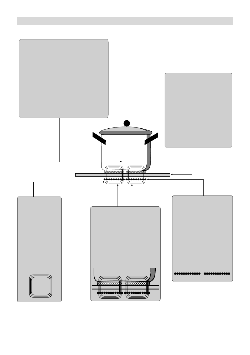
FIG. 1
- Pan with ferromagnetic base
- Hrnec se dnem z feromagnetického materiálu
- Hrniec s dnom z feromagnetického materiálu
- Naczynie ze spodem wykonanym z materiału o
właściwościach ferromagnetycznych
- Κατσαρλα µε βάση απ σιδηροµαγνητικ υλικ
- Кастрюля с дном из ферромагнитного материала
- Ferromágneses aljú edény
- Каструля з дном із феромагнету
- Indas feromagnetiniu pagrindu
- Glass-ceramic cooker top
- Sklokeramická varná deska
- Sklokeramická varná doska
- Ceramiczna płyta grzejna
- Υαλοκεραµική επιφάνεια
- Ветрокерамическая варочная панель
- Üvegkerámia főzőlap
- Склокерамічна поверхня
- Stiklo keramikos viryklës pavirðius
- Magnetic field
- Magnetické pole
- Magnetické pole
- Pole magnetyczne
- Μαγνητικ πεδίο
- Магнитное поле
- Mágneses tér
- Магнітне поле
- Magnetinis laukas
- Generator
- Generátor
- Generátor
- Generator
- Γεννήτρια
- Генератор
- Generátor
- Генератор
- Generatorius
- 3 -
- Archimedean spiral coil
- Cívka ve tvaru Archimedovy spirály
- Cievka v tvare Archimedovej špirály
- Cewka w formie spirali Archimedesa
- Πηνίο σπιράλ του Αρχιµήδη
- Спиральная катушка Архимеда
- Arkhimédészi fűtőspirál
- Котушка з архімедовою спіраллю
- Archimedo spiralës ritë
Page 4
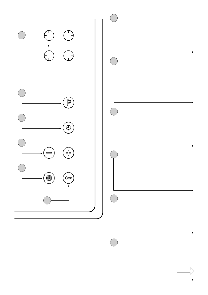
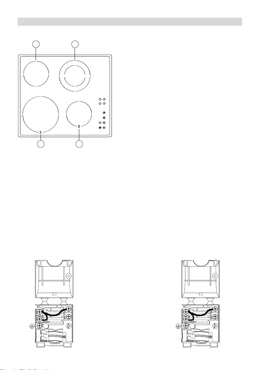
FIG.2
B
F
E
C
A
- Selection of the cooking area
B
- Volba varné zóny
- Voľba varnej zóny
- Wybór pola grzejnego
- Επιλογή τησ περιοχήσ µαγειρέµατοσ
- Сектор варочной зоны
- A főzőfelület kiválasztása
- Вибір зони приготування їжі
- Virimo vietos pasirinkimas
- Power intensifier (Booster)
F
- Zesilovač výkonu (Booster)
- Zosilňovač výkonu (Booster)
- Włączanie funkcji zwiększania mocy (funkcja
Booster)
- Ενισχυτήσ ισχύοσ (Βooster)
- Ускоритель нагрева (вольтодобавочное
устройство)
- Teljesítménynövelő (Booster)
- Підсилювач потужності (Бустер)
- Ákaitinimo greitintuvas (Booster)
- Timer
E
- Časovač
- Časovač
- Minutnik
- Timer
- Таймер
- Időzítés
- Таймер
- Laikmatis
- Temperature adjustment keys
C
- Tlačítka regulace teploty
- Tlačidlá regulácie teploty
- Przyciski regulacji temperatury
- Κουµπιά ρύθµισησ θερµοκρασίασ
- Кнопки регуляции температуры
- Hőmérséklet-szabályozó gombok
- Кнопки регулювання температури
- Temperatûros reguliavimo mygtukai
- ON/OFF
D
A
- ZAPNUTÍ / VYPNUTÍ
- ZAPNUTIE / VYPNUTIE
- WŁ./WYŁ.
- ON / OFF
- ВКЛ./ВЫКЛ.
- BE / KI
- Ввімкн/Вимкн
- ON / OFF (ájungimo/iðjungimo)
D
- Key
- Tlačítko se symbolem klíče
- Tlačidlo so symbolom kľúča
- Przycisk blokady
- Κουµπί κλειδιού
- Кнопка-ключ
- Gyermekzár gomb
- Кнопка з ключем
- Uþrakinimo Mygtukas
- 4 -
Page 5
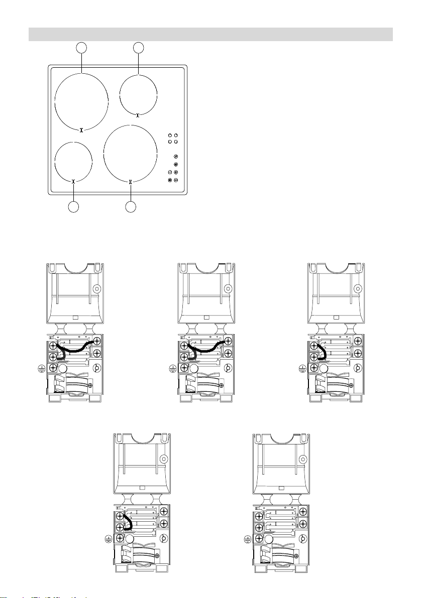
FIG.3A
4i
1 1
1. Cooking by INDUCTION area
1. INDUKČNÍ varné zóny
BOOSTER
1 1
FIG.3B
220-240V~ H05V2V2-F 3G 2.5mm
L
N
1. INDUKČNÉ varné zóny
1. Pola grzejne INDUKCYJNE
1. Ζώνεσ µαγειρέµατοσ µε ΕΠΑΓΩΓΗ
1. ИНДУКЦИОННЫЕ конфорки
1. INDUKCIÓS főzőfelületek
1. Зони нагрівання за допомогою ІНДУКЦІЇ
1. Indukcines kaitvietes
2
220-240V2~ H05V2V2-F 3G 2.5mm
2
380-415V2N~ H05V2V2-F 3G 2.5mm
L
1
L
2
L
1
L
N
2
2
220-240V3~ H05V2V2-F 3G 2.5mm
L
2
L
L
1
3
2
380-415V3N~ H05V2V2-F 3G 2.5mm
L
2
L
1
- 5 -
L
N
2
3
Page 6
2i
FIG.4A
2 2
BOOSTER
1.Cooking by INDUCTION area
2. Cooking by RADIATION area
1. INDUKČNÍ varné zóny
2. VYZAŘOVACÍ varné zóny
1. INDUKČNÉ varné zóny
2. VYŽAROVACIE varné zóny
1. Pola grzejne INDUKCYJNE
2. Pola SZYBKOGRZEJNE
1. Ζώνεσ µαγειρέµατοσ µε ΕΠΑΓΩΓΗ
2. ΑΚΤΙΝΟΒΟΛΕΣ περιοχέσ µαγειρέµατοσ
1. ИНДУКЦИОННЫЕ конфорки
2. Нагревательные зоны
1. INDUKCIÓS főzőfelületek
2. SUGÁRZÓ főzőfelületek
1 1
1. Зони нагрівання за допомогою ІНДУКЦІЇ
2. Зони нагрівання за допомогою ВИПРОМІНЮВАННЯ
1. Indukcines kaitvietes
2. Hi-light kaitinimo elementai
FIG.4B
220-240V~ H05V2V2-F 3G 2.5mm
L
N
2
220-240V2~ H05V2V2-F 3G 2.5mm
2
L1
L2
- 6 -
Page 7
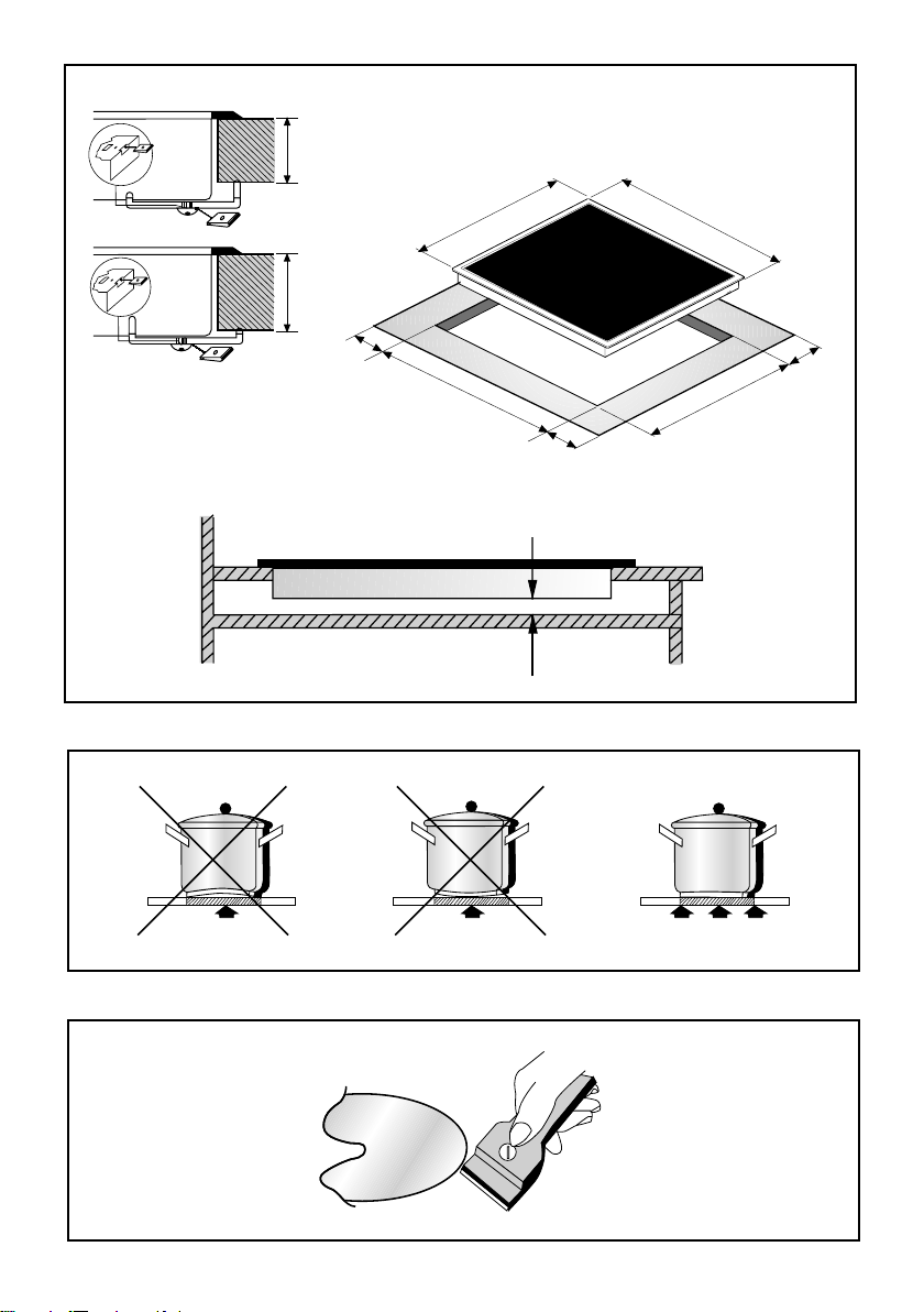
FIG.5
A
30 mm
40 mm
Min
C
50
510
560 - 750
Min
50
25
min.
580 - 770
490
B
53.5
Min
FIG.6
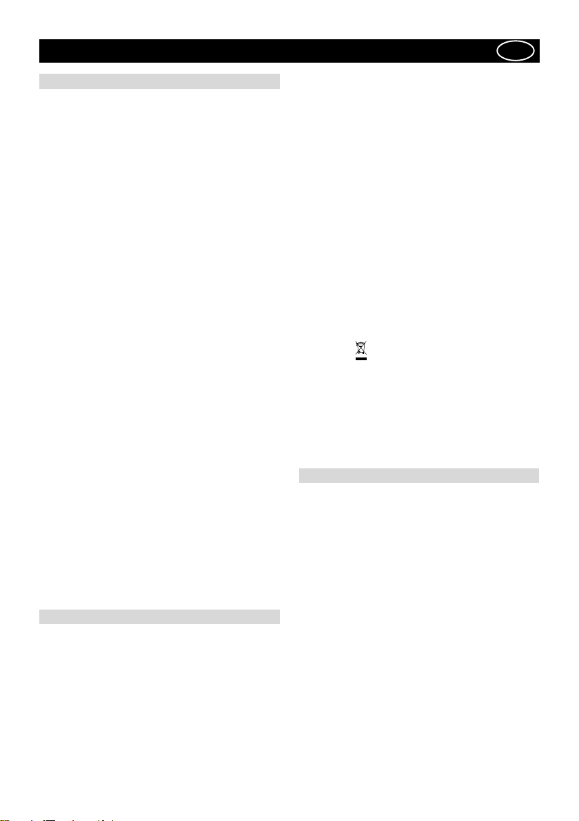
FIG.7
- 7 -
Page 8
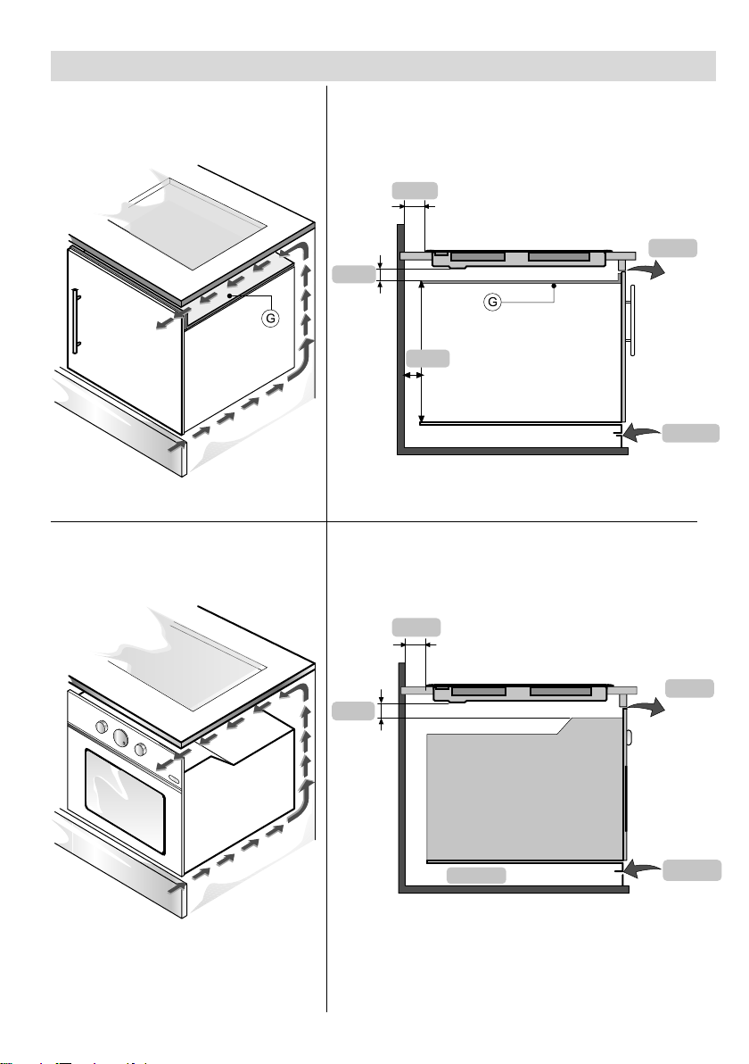
FIG.8 A FIG.8 B
25mm
FIG.9 A FIG.9 B
50 mm
4 mm
80 mm
500 x 10
40mm
- 8 -
50 mm
500 x 50
4 mm
500 x 10
Page 9
ENGLISH
GB
GENERAL
Carefully read the contents of this leaflet since it provides important instructions regarding safety of installation, use and maintenance.
Keep the leaflet for possible future consultation. All the
operations relating to installation (electrical connections)
must be carried out by specialised personnel in conformity with the regulations in force.
1.1 THE PRINCIPLE OF INDUCTION
The system of cooking by induction is based on the
physical phenomenon of magnetic induction.
The fundamental feature of this system is direct transfer
of heat energy from the generator to the pan without
intermediate means (different from traditional cooker tops
see fig.1).
1.2 ADV ANT AGES
If you compare your electric cooker tops, with the
induction cooker top, the result will be:
- Safer: low temperature on the glass surface
- Quicker: brief heating times.
- More precise: the top reacts immediately to your
commands
- More efficient: 90% of the energy absorbed is tran-
sformed into heat.
1.3 COOKING VESSELS fig.6
Cooking by induction uses magnetism to generate heat.
The vessels must therefore contain iron.
Check if the vessel material is magnetic using a magnet.
Important:
T o prev ent permanent damage to the cooker surface, do
not use:
- pans with bases that are not perfectly flat.
- metal pans with enamelled bases.
- Do not use pans with rough bases as they may scratch
the hob’s surface
For best results use pans of the same diameter as the
induction plate, so that they can be recognised by the
magnetic sensor.
SAFETY WARNINGS
This apparatus is not suitable for use by children or
persons who need supervision.
Do not allow children to play with the apparatus.
Before using the induction cooker top it is important to
check that the apparatus is compatible with anyone who
has a pacemaker and active surgical implants.
IMPORTANT
- metal objects such as knives, forks, spoons or lids
must not be placed on the cooker surface as they can
get hot.
- after use, switch the cooker off using the control device
and do not rely on the pan detector.
- avoid liquid spilling, therefore to boil or heat liquids
reduce the heat supply.
- do not leave the heating elements switched on with
empty vessels or without vessels.
- when you have finished cooking, switch off the relative
resistance using the control indicated below.
- never use aluminium foil for cooking, or never place
products wrapped in aluminium foil onto the cooking
surface. The aluminium would melt and damage your
apparatus irreversibly.
- Never heat a tin or can of food without opening it – it
could explode! This warning applies to hobs of all types.
A TTENTION: Steam cleaner s must not be used.
A TTENTION: If the surface is crac ked, switch the apparatus off to prevent electric shocks
This appliance conforms to the European Directive EC/
2002/96, Waste Electrical and Electronic Equipment
(WEEE). By making sure that this appliance is disposed
of in a suitable manner, the user is helping to prevent
potential damage to the environment or to public health.
The symbol on the product or on the accompanying
paperwork indicates that the appliance should not be
treated as domestic waste, but should be delivered to a
suitable electric and electronic appliance recycling
collection point. Follow local guidelines when disposing
of waste. For more information on the treatment, re-use
and recycling of this product, please contact your local
authority, domestic waste collection service or the shop
where the appliance was purchased.
INST ALLA TION INSTR UCTIONS
These instructions address specialised installers and
serve as a guide for installation, adjustment and maintenance in conformity with the laws and regulations in
force.
POSITIONING (fig.5)
The appliance is made for fixing into a worktop, as shown
in the relevant figure. Apply the supplied sealant to the
entire perimeter of the hob and insert it into the fitment
hole (for sizing see fig. 5B).
Fix the appliance into the worktop with the 4 stays, rotating them according to the top’s depth (fig. 5A).
If the underside of the appliance will be accessible after
installation, a separator panel G (fig. 8A) will need to be
mounted maintaining the distances shown (fig. 8B).
If the appliance is installed over an oven the panel is not
necessary (fig. 9A - 9B).
IMPORTANT: if there is an oven under the induction hob
it is advisable for it to have a cooling fan.
Do not use the induction hob while PYROLITIC cleaning is
in process.
WARNING: to allow the circulation of as much fresh air as
- 9 -
Page 10

necessary, there must be at least 40 mm between the
induction hob module and any appliance installed under it
(fig. 9B).
In any event, adequate aeration must be provided.
T o allow fresh air circulation there must be openings in the
kitchen furniture (fig. 8A-9A) of the sizes indicated in fig.
8B-9B.
ELECTRICAL CONNECTIONS (Fig.3B - Fig.4B)
Before making the electrical connections, check that:
- the ground cable is 2 cm longer than the other cables;
- the system ratings meet the ratings indicated on the
identification plate fixed on the lower part of the worktop;
- the system is fitted with efficient earthing compliant
to the laws and regulations in force.
Earthing is obligatory by law.
If the domestic appliance is not fitted with a cable and/
or relevant plug, use material suited to the absorption
value indicated on the identification plate and the operating temperature. At no point must the cable reach a
temperature 50°C higher than room temperature.
If wishing to make a direct connection to the mains, an
omnipolar switch must be interposed with a minimum
opening of 3 mm between the contacts and suited to the
load indicated on the plate and conform to the regulations in force (the yellow/green ground conductor must
not be interrupted by the switch). When the appliance
has been installed, the omnipolar switch must be easily
reachable.
USE AND MAINTENANCE
USE (Fig.2)
Press key A to switch the cooker top on.
Press one of the keys in section B corresponding to the
cooking area you intend to use.
Select cooking power using the + / - keys in section C
(number 9 on the display corresponds to the maximum
temperature and 1 to the minimum).
You can disconnect the cooking area by pressing the
symbols + and - at the same time.
To prevent use or cleaning of the cooker surface by
children, it is possible to block all functions by pressing
the D key.
If the small hotplate is equipped with an extended hotplate ring then the second zone will activate when the
corresponding knob P is touched and held for 3 seconds (fig. 2 F).
At this point the hotplate will be ignited and the temperature may be regulated using the - or + knobs.
BOOSTER:
The appliance is supplied with a Booster (only in the
cooking area indicated in fig.3A – 4A), on the basis of
the model you own.
To activate the Booster, switch the interested cooking
area on at any power level and press key P (fig. 2F). This
allows to reach higher temperatures in a short time disbursing the maximum power possible. Once the function
is activated a red LED and a P will appear on the display
for ten minutes. After this time the cooking area will
automatically return to power level 9.
If the Booster is activated at the same time in other
parts of the cooking area, the power will be slightly
lessened until the end of functioning.
Timer:
The timer can be used for any selected area.
Select the area where you want to use the timer and
then, by pressing the E key, activate the timer and using
+ and - choose the cooking time.
Once cooking time is over, the timer switches off the
area and deactivates the selection.
An acoustic signal can be heard for 30 seconds indicating
the end of timer activation.
IMPORTANT: To avoid damage to the electronic circuitry,
the hob is equipped with a safety device to prevent
overheating.
Should this cut in, wait until the hob has cooled down
before using it again.
MAINTENANCE
Remove any residues of food and drops of grease from
the cooking surface using the special scraper supplied
on request (Fig.7)
Clean the heated area as thoroughly as possible using
SIDOL, ST AHLFIX or similar products and a cloth/paper ,
then rinse with water and dry with a clean cloth.
Using the special scraper (optional) immediately remove
any fragments of aluminium and plastic material that
have unintentionally melted on the heated cooking area
or residues of sugar or food with a high sugar content
(Fig.7). In this way, any damage to the cooktop surface
is prevented.
Under no circumstances use abrasive sponges or irritating chemical detergents such as oven sprays or stain
removers.
THE MANUFA CTURER DECLINES ALL RESPONSIBILITY FOR EVENTUAL DAMAGES CAUSED BY BREACHING THE ABOVE WARNINGS.
- 10 -
Page 11

ČESKY
ZÁKLADNÍ ÚDAJE
Přečtěte si pozorně obsah tohoto návodu, protože je
zdrojem důležitých pokynů týkajících se bezpečnosti
instalace, použití a údržby. Návod uschovejte pro jakoukoli
další konzultaci. Všechny operace související s instalací
(elektrické zapojení) musí být provedeny specializovaným
personálem v souladu s platnými normami.
1.1 PRINCIP INDUKCE
Indukční varný systém využívá fyzikální jev magnetické
indukce.
Základní vlastností tohoto systému je přímý přenos energie z generátoru na hrnec (na rozdíl od klasických varných
desek - obr. 1).
1.2 VÝHODY
Při srovnání s elektrickými varnými deskami je vaše
indukční varná deska:
- Bezpečnější: nižší teplota na skleněném povrchu
- Rychlejší: kratší doby potřebné k ohřátí jídla.
- Přesnější: varná deska okamžitě reaguje na vaše příkazy
- Účinnější: 90% přijaté energie se promění na teplo.
1.3 NÁDOBY NA VAŘENÍ - obr.6
Indukční vaření využívá magnetismus pro vytváření tepla.
Použité nádoby proto musí obsahovat železo. To, zda je
příslušný hrnec magnetický, můžete zjistit použitím
jednoduchého magentu.
Dùležitá informace:
Aby se zabránilo trvalému poškození povrchu desky,
nepoužívejte:
- nádoby s nedokonale rovným povrchem.
- kovové nádoby se smaltovaným povrchem
- nepoužívejte nádoby s drsným povrchem, aby se zabránilo
poškrábání plochy varné desky.
Ve snaze o dosažení co nejlepších výsledků doporučujeme
používat hrnce s průměrem odpovídajícím indukční plotně,
aby byla umožněna identifikace ze strany magnetického
snímače.
BEZPEČNOSTNÍ POKYNY
Toto zařízení není vhodné k použití dětmi nebo
nesvéprávnými osobami.
Dávejte pozor, aby si děti se zařízením nehrály.
Pro uživatele kardiostimulátorů a aktivních zařízení je
důležité před použitím indukční varné desky zkontrolovat,
zda jej jejich stimulátor kompatibilní se zařízením.
DŮLEŽITÁ INFORMACE
- magnetické předměty jako nože, vidličky nebo víka se
nesmí klást na povrch varné desky, protože by mohlo dojít
k jejich ohřevu.
- Po použití vypněte varnou desku prostřednictvím
ovládacího zařízení a nespoléhejte se pouze na snímač
kontroly přítomnosti hrnců.
- zabraňte úniku tekutiny, a proto při uvádění tekutin do
varu nebo při jejich ohřevu snižte přívod tepla.
- nenechávejte topné články zapnuté, když jsou na nich
uložené prázdné hrnce nebo pánve nebo když na nich
nejsou uložené žádné nádoby.
- po ukončení vaření vypněte příslušnou zónu
prostřednictvím níže uvedeného ovládacího prvku.
- k vaření nikdy nepoužívejte alobalovou fólii a také nikdy
neklaďte přímo na varnou desku produkty zabalené do
alobalu. Došlo by k rozpuštění hliníku a trvalému poškození
vašeho zařízení.
- Nikdy neohřívejte konzervu ani plechovou nádobu
obsahující potraviny bez jejího předchozího otevření. mohla
by explodovat! Toto upozornění platí také pro všechny
ostatní druhy varných desek.
UPOZORNĚNÍ: K čištění zařízení se nesmí používat parní
čistič.
UPOZORNĚNÍ: Když je povrch prasklý, vypněte zařízení,
abyste zabránili případnému zásahu elektrickým
proudem.
Toto zařízení je označeno v souladu s Evropskou směrnicí
2002/96/ES, Waste Electrical and Electronic Equipment
(WEEE). Tím, že se uživatel ujistí o správné likvidaci
tohoto výrobku, přispívá k předcházení případným
negativním následkům na životní prostředí a na zdraví.
Symbol
poukazuje na to, že se s tímto výrobkem nesmí zacházet
jako s běžným domovním odpadem, ale musí se odeslat
do vhodné sběrny určené pro recyklaci elektrických a
elektronických zařízení. Zařízení se musíte zbavit
v souladu s místními předpisy pro likvidaci
odpadu.Podrobnější informace o zacházení s tímto
výrobkem, jeho opětovným použitím a recyklací můžete
získat, když se obrátíte na příslušný místní úřad, sběrnou
službu domovního odpadu nebo obchod, ve kterém jste
výrobek zakoupili.
na výrobku nebo na přiložené dokumentaci
POKYNY K INSTALACI
Tyto pokyny jsou určeny pro specializovaného instalatéra
a slouží jako návod pro instalaci, regulaci a údržbu
v souladu s platnými zákony a normami.
UMÍSTĚNÍ (Obr.5)
Tento elektrický spotřebič byl vyroben tak, aby se dal
zasunout do pracovní plochy způsobem znázorněným
na specifickém obrázku.
Podél otvoru v pracovní ploše připravte uzavírací materiál
a vložte do otvoru samotnou varnou desku (rozměry
výřezu jsou uvedeny na obr. 5B).
Zajistěte elektrický spotřebič na pracovní ploše
prostřednictvím 4 držáků; držáky natočte potřebným
způsobem s ohledem na tloušťku samotné plochy (obr. 5A).
Když je po instalaci spodní část zařízení přístupná, je
třeba provést montáž oddělovacího panelu G (Pbr.8A)
za dodržení uvedených vzdáleností (Obr. 8B).
Když je zařízení nainstalováno nad sporákem, panel
- 11 -
CZ
Page 12

není potřebný (Obr. 9A – 9B)
DŮLEŽITÁ INFORMACE: když je sporák umístěn pod
indukční varnou deskou, je vhodné, aby byl vybaven
chladicím ventilátorem.
Nepoužívejte indukční varnou deku během použití
PYROLYTICKÉHO čištění.
UPOZORNĚNÍ: aby byla umožněna cirkulace co největšího
možného množství vzduchu, je třeba dodržet minimální
vzdálenost 40 mm mezi modulem a jakýmkoli jiným
zařízením nainstalovaným pod úrovní indukční varné desky
(obr.9 B). V každém případě je třeba umožnit vhodnou
ventilaci.
Aby byla umožněna cirkulace čerstvého vzduchu, musí
být v kuchyňské lince zhotoveny otvory (obr.8A – 9A) za
dodržení kvót uvedených na obr. 8B-9B.
ELEKTRICKÉ ZAPOJENÍ (Obr.3B - Obr.4B)
Před provedením elektrického zapojení se ujistěte, že:
- elektrický kabel uzemnění je o 2 cm delší než ostatní
kabely;
- vlastnosti rozvodu odpovídají pokynům uvedeným na
identifikačním štítku, který se nachází na spodní straně
pracovní plochy.
- je rozvod vybaven funkčním uzemněním odpovídajícím
platným normám a zákonným nařízením.
Uzemnění je povinné a tato povinnost vyplývá ze zákona.
V případě, že elektrický spotřebič není vybaven kabelem
a/nebo příslušnou zástrčkou, použijte materiál vhodný
pro příkon uvedený na identifikačním štítku a pro danou
provozní teplotu. Teplota nesmí v žádném místě
přesáhnout hodnotu o 50°C vyšší, než je teplota prostředí.
V případě přímého připojení k elektrickému rozvodu je
třeba mezi spotřebič a rozvod zapojit omnipolární vypínač
s minimální vzdáleností kontaktů 3mm, vhodný pro zátěž
uvedenou na štítku a odpovídající platným normám
(žlutozelený zemnicí vodič nesmí být přerušen
přepínačem).
Po ukončení instalace zařízení musí být omnipolární
vypínač lehce přístupný.
POUŽITÍ A ÚDRŽBA
POUŽITÍ (Obr.2)
Zapněte zařízení stisknutím tlačítka A.
Stiskněte jedno z tlačítek volby B odpovídající varné
zóně, kterou hodláte použít.
S použitím tlačítek zvolte požadovaný varný výkon
+ / - volby C (číslo 9 na displeji odpovídá maximální
teplotě a číslo 1 minimální).
Varná zóna může být vyloučena současným stisknutím
symbolů + a -.
Abyste zabránili použití nebo čištění povrchu desky dětmi,
je možné zablokovat všechny funkce tlačítkem se
symbolem klíče D.
Když je varná deska vybavena 2 zónami ohřevu, za účelem
její aktivace držte prst po dobu přibližně 3 sekund nad
odpovídajícím tlačítkem P (obr. 2 F). Nyní je možné zvýšit
nebo snížit teplotu prostřednictvím tlačítek + nebo -.
Booster:
Na základě modelu, který vlastníte, je zařízení vybaveno
(pouze ve varné zóně označené obr.3A - 4A) Boosterem.
Jeho aktivace se provádí zapnutím příslušné varné zóny
při libovolném výkonu a stisknutím tlačítka P (obr.2 F).
To umožní dosažení vyšší teploty v průběhu kratší doby
s použitím maximálního možného výkonu. Po aktivaci
dané funkce se rozsvítí červená LED a na displeji se
zobrazí P na dobu 10 minut, po jejichž uplynutí se varná
zóna automaticky vrátí na úroveň výkonu 9.
Když je Booster aktivován současně také u jiných
varných zón, dojde na nich k lehkému poklesu výkonu,
který bude trvat až do ukončení používání dané funkce.
Časovač:
Pro každou zvolenou zónu je možné použít časovač.
Zvolte zónu, ve které si přejete použít časovač.
Stiskněte tlačítko E a prostřednictvím tlačítek + a - zvolte
požadovanou dobu vaření.
Po uplynutí nastavené doby vaření časovač vypne danou
zónu a zruší volbu.
Po dobu 30 sekund bude aktivní akustický signál
poukazující na uplynutí doby nastavené časovačem.
DŮLEŽITÁ INFORMACE: Aby se zabránilo poškození
elektronických obvodů, je systém vybaven bezpečnostní
ochranou proti přehřátí.
V případě jejího zásahu vyčkejte před opětovným
použitím varné desky na její ochlazení.
ÚDRŽBA
Speciální škrabkou dodávanou na přání (Obr.7) odstraňte
případné zbytky jídla a kapky tuku z varné plochy .
Co nejlépe vyčistěte ohřátý prostor; použijte SIDOL,
STAHLFIX nebo podobné produkty a čisticí papír, následně
opláchněte vodou a osušte čistým hadrem.
Prostřednictvím speciální škrabky (volitelné příslušenství)
okamžitě odstraňte z ohřátého prostoru zbytky
alobalových folií a plastového materiálu, které se zde
náhodně zachytily, nebo zbytky cukru a jídel se zvýšeným
obsahem cukru (Obr.7). Tímto způsobem je možné
zabránit všem druhům poškození povrchu varné desky.
K čištění varné desky se v žádném případě nesmí
používat abrazivní houby ani leptavé chemické produkty,
jako např. sprej nebo přípravky na odstranění skvrn.
VÝROBCE NEPONESE ŽÁDNOU ODPOVĚDNOST
V PŘÍPADĚ NEDODRŽENÍ VÝŠE UVEDENÝCH
BEZPEČNOSTNÍCH POKYNŮ.
- 12 -
Page 13

SLOVENSKY
ZÁKLADNÉ ÚDAJE
Prečítajte si pozorne obsah tohto návodu, pretože je
zdrojom dôležitých pokynov, týkajúcich sa bezpečnosti,
inštalácie, použitia a údržby. Návod uschovajte pre
akúkoľvek ďalšiu konzultáciu. Všetky operácie súvisiace
s inštaláciou (elektrické zapojenie) musia byť vykonané
špecializovaným personálom v súlade s platnými
normami.
1.1 PRINCÍP INDUKCIE
Indukční varný systém využíva fyzikálny jav magnetickej
indukcie.
Základnou vlastnosťou tohto systému je priamy prenos
energie z generátora na hrniec (na rozdiel od klasických
varných dosiek - obr. 1).
1.2 VÝHODY
Pri porovnaní s elektrickými varnými doskami je vaša
indukčná varná doska:
- Bezpečnejšia: nižšia teplota na sklenom povrchu
- Rýchlejšia: kratšie doby potrebné na ohriatie jedla.
- Presnejšia: Varná doska okamžite reaguje na vaše
príkazy
- Účinnejšia: 90% prijatej energie sa premení na teplo.
1.3 NÁDOBY NA VARENIE - obr.6
Indukčné varenie využíva magnetizmus na vytváranie
tepla. Použité nádoby preto musia obsahovať železo. To,
či je príslušný hrniec magnetický, môžete zistiť s použitím
jednoduchého magnetu.
Dôležitá informácia:
Aby sa zabránilo trvalému poškodeniu povrchu dosky,
nepoužívajte:
- nádoby s nedokonale rovným povrchom.
- kovové nádoby so smaltovaným povrchom
- nepoužívajte nádoby s drsným povrchom, aby sa
zabránilo poškrabaniu plochy varnej dosky.
V snahe o dosiahnutie čo najlepších výsledkov,
odporúčame používať hrnce s priemerom odpovedajúcim
indukčnej platni, aby bola umožnená identifikácia zo
strany magnetického snímača.
BEZPEČNOSTNÉ POKYNY
Nie je vhodné, aby toto zariadenie používali deti alebo
nesvojprávne osoby.
Dávajte pozor, aby sa deti so zariadením nehrali.
Pre užívateľov srdcových strojčekov a aktívnych
zariadení je dôležité pred použitím indukčnej varnej dosky
skontrolovať, či je ich stimulátor kompatibilný so
zariadením.
DÔLEŽITÁ INFORMÁCIA
- magnetické predmety ako nože, vidličky alebo veká
nesmú byť kladené na povrch varnej dosky, pretože by
mohlo dôjsť k ich ohrevu.
- Po použití vypnite varnú dosku prostredníctvom
ovládačov a nespoliehajte sa len na snímač kontroly
SK
prítomnosti hrncov.
- zabráňte úniku tekutín - pri uvádzaní tekutín do varu,
alebo pri ich ohreve, znížte teplotu ohrevu.
- nenechávajte ohrievacie články zapnuté, keď sú na
nich uložené prázdne hrnce alebo panvice, alebo keď na
nich nie sú uložené žiadne nádoby.
- po ukončení varenia vypnite príslušnú zónu
prostredníctvom následne uvedeného ovládacieho prvku.
- na varenie nikdy nepoužívajte alobalovú fóliu a takisto
nikdy neklaďte priamo na varnú dosku produkty zabalené
do alobalu. Došlo by k roztopeniu hliníka a trvalému
poškodeniu vášho zariadenia.
- Nikdy neohrievajte neotvorenú konzervu alebo plechovú
nádobu s potravinami: mohla by vybuchnúť! Toto
upozornenie platí aj pre všetky ostatné druhy varných
dosiek.
UPOZORNENIE: Na čistenie zariadenia nesmie byť
použitý parný čistič.
UPOZORNENIE: Keď je povrch prasknutý, vypnite
zariadenie, aby ste zabránili prípadnému zásahu
elektrickým prúdom.
Toto zariadenie je označené v súlade s Európskou
smernicou 2002/96/ES Waste Electrical and Electronic
Equipment (WEEE). Uistením sa o správnom spôsobe
likvidácie tohto výrobku sa užívateľ podieľa na
predchádzaní možným negatívnym následkom pre životné
prostredie a pre zdravie. Symbol na výrobku alebo
v dokumentácii, ktorá je k nemu priložená, poukazuje
na to, že s týmto výrobkom nesmie byť narábané ako
s domovým odpadom, ale musí byť odovzdaný do vhodnej
zberne pre recykláciu elektrických a elektronických
zariadení. Je potrebné sa ho zbaviť v súlade s miestnymi
predpismi pre likvidáciu odpadu. Za účelom získania
podrobnejších informácií týkajúcich sa spracovania,
opätovného použitia a recyklácie tohoto výrobku sa
obráťte na vhodný úrad s miestnou pôsobnosťou, službu
zberu domového odpadu alebo obchod, kde bol tento
výrobok zakúpený.
POKYNY NA INŠTALÁCIU
Tieto pokyny sú určené pre špecializovaného inštalatéra
a slúžia ako návod na inštaláciu, reguláciu a údržbu
v súlade s platnými zákonmi a normami.
UMIESTNENIE (Obr.5)
Tento elektrický spotrebič bol vyrobený tak, aby mohol
byť vložený do pracovnej plochy, spôsobom znázorneným
na príslušnom obrázku.
Po obvode otvoru v pracovnej ploche pripravte tesniaci
materiál a vložte do otvoru samotnú varnú dosku (rozmery
výrezu sú uvedené na obr. 5B).
Zaistite elektrický spotrebič na pracovnej ploche
prostredníctvom 4 držiakov ich natočením príslušným
spôsobom, s ohľadom na hrúbku samotnej dosky (obr. 5A).
Keď je po inštalácii spodná časť zariadenia prístupná, je
potrebné vykonať montáž oddeľovacieho panelu G
(Pbr.8A) za dodržania uvedených vzdialeností (Obr. 8B).
- 13 -
Page 14

Keď je zariadenie nainštalované nad sporákom, panel
nie je potrebný (Obr. 9A - 9B)
DÔLEŽITÁ INFORMÁCIA: keď je sporák umiestnený pod
indukčnou varnou doskou, je vhodné aby bol vybavený
chladiacim ventilátorom.
Nepoužívajte indukčnú varnú dosku počas použitia
PYROLITICKÉHO čistenia.
UPOZORNENIE: aby bola umožnená cirkulácia čo
najväčšieho množstva vzduchu, je potrebné dodržať
minimálnu vzdialenosť 40 mm medzi modulom
a akýmkoľvek iným zariadením nainštalovaným pod
úrovňou indukčnej varnej dosky (obr.9 B). V každom
prípade je potrebné umožniť vhodnú ventiláciu.
Aby bola umožnená cirkulácia čerstvého vzduchu,
v kuchynskej linke musia byť vyhotovené otvory (obr.8A
– 9A), pričom musia byť dodržané rozmery uvedené na
obr. 8B-9B.
ELEKTRICKÉ ZAPOJENIE (Obr.3B - Obr.4B)
Pred vykonaním elektrického zapojenia sa uistite, že:
- elektrický kábel uzemnenia je o 2 cm dlhší ako ostatné
káble;
- rozvod je v súlade s požiadavkami uvedenými na
identifikačnom štítku umiestnenom na spodnej strane
pracovnej plochy.
- rozvod je vybavený funkčným uzemnením,
odpovedajúcim platným normám a zákonným nariadeniam.
Uzemnenie je povinné a táto povinnosť vyplýva zo zákona.
V prípade, keď elektrický spotrebič nie je vybavený káblom
a/alebo príslušnou zástrčkou, použite materiál vhodný
pre príkon uvedený na identifikačnom štítku a pre danú
prevádzkovú teplotu. Teplota nesmie na žiadnom mieste
presiahnuť hodnotu o 50°C vyššiu ako je teplota prostredia.
V prípade priameho pripojenia k elektrickému rozvodu je
potrebné medzi spotrebič a rozvod zapojiť omnipolárny
vypínač, s minimálnou vzdialenosťou kontaktov 3mm,
vhodný pre záťaž uvedenú na štítku a odpovedajúci
platným normám (žltozelený zemniaci vodič nesmie byť
prerušený prepínačom).
Po ukončení inštalácie zariadenia musí byť omnipolárny
vypínač ľahko prístupný.
POUŽITIE A ÚDRŽBA
POUŽITIE (Obr.2)
Zapnite zariadenie stlačením tlačidla A.
Stlačte jedno z tlačidiel voľby B odpovedajúce varnej
zóne, ktorú chcete použiť.
S použitím tlačidiel zvoľte požadovaný varný výkon
+ / - voľby C (číslo 9 na displeji odpovedá maximálnej a
číslo 1 minimálnej teplote).
Varná zóna môže byť vylúčená súčasným stlačením
symbolov + a -.
Aby ste zabránili použitiu alebo čisteniu povrchu dosky
deťmi, je možné zablokovať všetky funkcie tlačidlom so
symbolom kľúča D.
Keď je varná doska vybavená dvomi ohrevnými zónami,
pre aktiváciu jednej z nich podržte prst približne po dobu
3 sekúnd nad príslušným tlačidlom P (obr. 2 F). Teraz je
možné zvýšiť alebo znížiť teplotu prostredníctvom tlačidiel
+ alebo -.
Booster:
Na základe modelu, ktorý vlastníte, je zariadenie
vybavené (len vo varnej zóne označenej obr.3A - 4A)
Boostrom.
Jeho aktivácia sa vykonáva zapnutím príslušnej varnej
zóny pri ľubovoľnom výkone a stlačením tlačidla P (obr.2
F). To umožní dosiahnutie vyššej teploty v priebehu kratšej
doby, s použitím maximálneho možného výkonu. Po
aktivácii danej funkcie sa rozsvieti červená LED dióda a
na displeji sa zobrazí symbol P na dobu 10 minút. Po ich
uplynutí sa varná zóna automaticky vráti na úroveň
výkonu 9.
Keď je Booster aktivovaný súčasne aj na iných varných
zónach, dôjde na nich k ľahkému poklesu výkonu,
trvajúcemu až do ukončenia používania danej funkcie.
Časovač:
Pre každú zvolenú zónu je možné použiť časovač.
Zvoľte zónu, v ktorej si želáte použiť časovač. Stlačte
tlačidlo E a prostredníctvom tlačidiel + a - zvoľte
požadovanú dobu varenia.
Po uplynutí nastavenej doby varenia časovač vypne
danú zónu a zruší voľbu.
Po dobu 30 sekúnd bude aktívny akustický signál,
upozorňujúci na uplynutie doby nastavenej časovačom.
DÔLEŽITÁ INFORMÁCIA: Aby sa zabránilo poškodeniu
elektronických obvodov, systém je vybavený
bezpečnostnou ochranou proti prehriatiu.
V prípade jej aktivácie, nechajte varnú dosku, pred jej
opätovným použitím, vychladnúť.
ÚDRŽBA
Odstráňte prípadné zvyšky jedla a kvapky tuku z plochy
varnej dosky, použitím špeciálnej škrabky, dodávanej na
želanie (Obr.7).
Čo najlepšie vyčistite ohrevný priestor s použitím SIDOLU,
STAHLFIXU alebo podobných produktov, a čistiaceho
papiera. Následne opláchnite vodou a osušte čistou
utierkou.
Prostredníctvom špeciálnej škrabky (voliteľné
príslušenstvo) okamžite odstráňte z ohriateho priestoru
zvyšky alobalových fólií a plastového materiálu, ktorý
bol náhodne rozliaty, alebo zvyšky cukru a jedál so
zvýšeným obsahom cukru (Obr.7). Týmto spôsobom je
možné zabrániť všetkým druhom poškodenia povrchu
varnej dosky.
V žiadnom prípade nesmú byť na čistenie varnej dosky
používané abrazívne špongie alebo leptavé chemické
produkty, ako napr. sprej alebo prípravky na
odstraňovanie škvŕn.
VÝROBCA NEPONESIE ŽIADNU ZODPOVEDNOSŤ
V PRÍPADE NEDODRŽANIA VYŠŠIE UVEDENÝCH
BEZPEČNOSTNÝCH POKYNOV.
- 14 -
Page 15

POLSKA
INFORMACJE OGÓLNE
Niniejszą instrukcję należy dokładnie przeczytać,
zwracając szczególną uwagę na ważne informacje
dotyczące bezpieczeństwa podczas instalacji,
użytkowania i konserwacji urządzenia. Instrukcję należy
zachować, tak by można było z niej korzystać również w
przyszłości. Wszystkie czynności związane z instalacją
(podłączenie do instalacji elektrycznej) powinny być
wykonywane przez wykwalifikowanych techników, w
sposób zgodny z obowiązującymi przepisami.
1.1 ZJAWISKO INDUKCJI ELEKTROMAGNETYCZNEJ
Płyta indukcyjna działa przy wykorzystaniu zjawiska
indukcji elektromagnetycznej. Podstawową cechą tej
technologii jest, w przeciwieństwie do płyt tradycyjnych,
bezpośrednie przekazywanie energii z generatora do
naczynia (patrz rys. 1).
1.2 ZALETY
W porównaniu z płytami elektrycznymi płyty indukcyjne
odznaczają się następującymi zaletami:
- Większe bezpieczeństwo: mniejsza temperatura
powierzchni płyty.
- Szybkość: krótszy czas gotowania potraw.
- Większa precyzja: płyta natychmiast reaguje na zmianę
ustawień.
- Większa sprawność: na ciepło zamieniane jest 90%
pobieranej energii.
1.3 NACZYNIA DO GOTOWANIA — rys. 6
W płytach indukcyjnych do wytwarzania ciepła używane
jest pole magnetyczne. Dlatego naczynia powinny być
wykonane z materiału zawierającego metale o
właściwościach ferromagnetycznych. To, czy materiał
ten ma właściwości magnetyczne, można sprawdzić za
pomocą zwykłego magnesu.
Ważne uwagi:
Aby uniknąć trwałego uszkodzenia powierzchni płyty,
nie należy używać:
- naczyń, których spód nie jest idealnie płaski;
- naczyń metalowych ze spodem emaliowanym;
- naczyń z chropowatym spodem, mogących powodować
jej zarysowanie.
W celu osiągnięcia najlepszych efektów zaleca się
używanie naczyń o średnicy podobnej do średnicy strefy
indukcyjnej, tak aby mógł je wykrywać czujnik
magnetyczny.
UWAGI DOTYCZĄCE BEZPIECZEŃSTWA
Urządzenie nie powinno być używane przez dzieci lub
osoby nie posiadające odpowiednich umiejętności.
Nie należy pozwalać dzieciom na bawienie się
urządzeniem.
W przypadku osób z wszczepionym rozrusznikiem serca
lub innym aktywnym implantem należy przed użyciem
płyty indukcyjnej sprawdzić, czy nie zakłóca ona działania
wszczepionych im urządzeń.
PL
WAŻNE
- Nie należy kłaść na powierzchni płyty metalowych
przedmiotów, takich jak noże, widelce czy łyżki, ponieważ
płyta może je wówczas nagrzać.
- Po zakończeniu gotowania należy wyłączyć płytę za
pomocą przycisku — nie należy polegać w tym względzie
jedynie na czujniku wykrywającym obecność naczynia.
- Należy unikać wylewania się na płytę płynów, dlatego
przy ich podgrzewaniu lub gotowaniu konieczne jest
zmniejszenie mocy grzania.
- Nie należy pozostawiać włączonych elementów
grzewczych, gdy garnek lub patelnia są puste lub gdy
na płycie nie stoją naczynia.
- Po zakończeniu gotowania należy wyłączyć odpowiednią
strefę za pomocą opisanych niżej przycisków.
- Nie należy bezwzględnie używać do gotowania folii
aluminiowej. Nie należy również kłaść na powierzchni
płyty produktów w opakowaniach aluminiowych. W takim
przypadku bowiem aluminium stopiłoby się, powodując
nieodwracalne uszkodzenie urządzenia.
- Nie należy podgrzewać zamkniętych puszek lub
opakowań metalowych z żywnością — mogłoby to
spowodować ich wybuch! Uwaga ta dotyczy wszystkich
typów płyt grzewczych.
UWAGA: Nie należy używać urządzeń do czyszczenia
parą.
UWAGA: Jeżeli powierzchnia płyty jest pęknięta, należy
wyłączyć urządzenie, aby uniknąć porażenia prądem
elektrycznym.
Niniejsze urządzenie oznaczone jest zgodnie z dyrektywa
europejska 2002/96/EC, Waste Electrical and Electronic
Equipment (WEEE). Upewniwszy się, że niniejszy produkt
zostanie zutylizowany we właściwy sposób, użytkownik
przyczynia się do ochrony przed potencjalnymi
konsekwencjami negatywnymi dla środowiska i zdrowia.
Symbol podany na produkcie lub na dokumentacji
towarzyszącej mu wskazuje, że produktu ten nie powinien
być traktowany jaki odpad domowy, lecz powinien być
przekazany w stosownym punkcie zbiórki w celu
odzyskania urządzeń elektrycznych i elektronicznych.
Pozbywać się go zgodnie z miejscowymi normami w
zakresie utylizacji odpadów. Dla uzyskania dodatkowych
informacji na temat traktowania, odzyskiwania i recyklingu
tego produktu, należy skontaktować się z odpowiednim
lokalnym biurem, służbą odpadów domowych lub ze
sklepem, w którym produkt został zakupiony.
INSTRUKCJA INSTALACJI
Niniejsza instrukcja przeznaczona jest dla techników
instalujących płyty. Opisuje instalację, regulację i
konserwację urządzenia. Czynności te powinny być
wykonywane przy zachowaniu obowiązujących przepisów.
USTAWIENIE (rys. 5)
Urządzenie jest przeznaczone do montażu w blacie
kuchennym w sposób pokazany na rysunku.
Nałóż masę uszczelniającą na całym obwodzie płyty i
włóż płytę w otwór (wymiary otworu podano na rys. 5B).
- 15 -
Page 16

Przytwierdź urządzenie za pomocą 4 uchwytów, obracając
je w zależności od grubości płyty (rys. 5A).
Jeśli po zainstalowaniu urządzenia jego dolna część jest
nadal łatwo dostępna, należy zamontować płytę oddzielającą
G (rys. 8A), zachowując odległości podane na rys. 8B.
Jeżeli urządzenie jest umieszczone nad piekarnikiem,
płyta oddzielająca nie jest potrzebna (rys. 9A-9B).
WAŻNE: Jeżeli pod płytą znajduje się piekarnik, powinien
on być wyposażony w wentylator chłodzący.
Nie należy używać płyty w czasie PIROLITYCZNEGO
czyszczenia piekarnika.
UWAGA: Aby umożliwić jak najlepszą cyrkulację
powietrza, pomiędzy płytą indukcyjną a umieszczonym
pod nią urządzeniem należy zachować odległość co
najmniej 40 mm (rys. 9B). Należy przy tym zapewnić
odpowiednią wentylację.
Meble kuchenne powinny mieć otwory (rys. 8A-9A)
pozwalające na odpowiednią cyrkulację powietrza. Ich
wymiary podano na rys. 8B-9B.
PODŁĄCZENIE DO SIECI ELEKTRYCZNEJ (rys. 3B-4B)
Przed podłączeniem urządzenia do sieci elektrycznej
należy sprawdzić, czy:
- przewód uziemienia jest dłuższy o 2 cm od pozostałych
przewodów;
- parametry sieci elektrycznej odpowiadają parametrom
urządzenia znajdującym się na tabliczce znamionowej
znajdującej się na dolnej części płyty;
- sieć jest wyposażona w przewód uziemienia, zgodny z
obowiązującymi przepisami.
Uziemienie jest wymagane przez obowiązujące przepisy.
W przypadku urządzenia, które nie jest wyposażone w
przewód zasilający, należy użyć przewodu odpowiedniego
dla mocy urządzenia podanej na tabliczce znamionowej
i dla temperatury pracy. Przewód nie powinien nagrzewać
się do temperatury wyższej niż 50°C powyżej temperatury
otoczenia.
Przy bezpośrednim podłączeniu urządzenia do sieci
elektrycznej należy zainstalować włącznik
wielobiegunowy, w którym odległość pomiędzy stykami
jest większa niż 3 mm, odpowiedni dla mocy podanej na
tabliczce znamionowej i obowiązujących przepisów
(włącznik nie powinien rozłączać obwodu uziemienia
(żółtozielony przewód)).
Wyłącznik wielobiegunowy musi być umieszczony w taki
sposób, aby był łatwo dostępny po zainstalowaniu
urządzenia.
UŻYTKOWANIE I KONSERWACJA
UŻYTKOWANIE (rys. 2)
Aby włączyć urządzenie, dotknij przycisku A.
Dotknij jednego z przycisków sekcji B odpowiadającego
polu grzejnemu, którego chcesz używać.
Ustaw moc grzania za pomocą przycisków
+ / - w sekcji C (wartość 9 odpowiada maksymalnej
temperaturze, a wartość 1 temperaturze minimalnej).
Pole grzejne można wyłączyć dotykając jednocześnie
przycisków + i -.
Aby uniemożliwić włączenie płyty i sterowanie nią
dzieciom, można zablokować jej wszystkie funkcje za
pomocą przycisku blokowania D.
W przypadku płyt z dwustrefowymi polami grzejnymi,
aby włączyć dwustrefowe pole grzejne, należy
przytrzymać odpowiedni przycisk P (rys. 2 F) przez około
3 sekundy. Można wówczas zmniejszyć lub zwiększyć
temperaturę pola za pomocą przycisków + i -.
Funkcja zwiększania mocy (funkcja Booster):
Urządzenie jest wyposażone w funkcję zwiększania mocy
pola grzejnego (tylko pole oznaczone na rys. 3A-4A)
(funkcja Booster).
Aby włączyć funkcję zwiększania mocy, należy włączyć
odpowiednie pole, ustawić dowolną moc i dotknąć
przycisku P (rys. 2F). Pozwala to, przy użyciu
maksymalnej możliwej mocy, na osiągnięcie wyższej
temperatury w krótkim czasie. Po jej włączeniu na 10
minut zaświeci się czerwona dioda LED wyświetlacza i
pojawi się na nim litera P. Po tym czasie pole grzejne
powróci automatycznie do grzania z mocą na poziomie
9.
Jeżeli w czasie działania funkcji zwiększania mocy
zostaną włączone inne pola grzejne, do końca działania
tej funkcji będą pracowały z nieco obniżoną mocą.
Minutnik:
Minutnika można używać dla dowolnego pola grzejnego:
Wybierz pole, dla którego chcesz użyć minutnika. Dotknij
przycisku E i za pomocą przycisków + oraz - ustaw
żądany czas gotowania.
Po zakończeniu gotowania pole zostaje wyłączone, a
jego wybór zostaje skasowany.
Koniec pracy minutnika sygnalizuje 30-sekundowy sygnał
akustyczny.
WAŻNE: Płyta grzewcza wyposażona jest w
zabezpieczenie przed przegrzaniem, zapobiegające
uszkodzeniu jej układów elektronicznych.
W przypadku, gdy włączy się to zabezpieczenie, przed
ponownym uruchomieniem płyty należy poczekać do
chwili, gdy urządzenie ochłodzi się.
KONSERWACJA
Pozostałości potraw i krople tłuszczu usuwa się z
powierzchni płyty przy pomocy specjalnego,
dostarczanego na zamówienie skrobaka (rys. 7).
Wyczyść jak najdokładniej powierzchnie grzewcze,
używając produktów marki SIDOL, STAHLFIX lub
podobnych oraz ręcznika papierowego, a następnie
spłucz je wodą i wytrzyj do sucha czystą ściereczką.
Kawałki folii aluminiowej i tworzyw sztucznych, które
stopiły się na powierzchni płyty oraz resztki cukru lub
potraw zawierających cukier należy jak najszybciej
usuwać z powierzchni grzewczych (za pomocą skrobaka
zamawianego oddzielnie; rys. 7). Można w ten sposób
uniknąć uszkodzenia płyty.
Do czyszczenia płyty nie wolno używać chropowatych
gąbek lub silnych chemicznych środków czyszczących,
takich jak aerozole do czyszczenia piekarnika lub środki
do usuwania plam.
PRODUCENT URZĄDZENIA NIE PONOSI
ODPOWIEDZIALNOŚCI ZA JAKIEKOLWIEK SZKODY
POWSTAŁE W WYNIKU NIEPRZESTRZEGANIA
OGÓLNYCH NORM BEZPIECZEŃSTWA LUB
NIESTOSOWANIA SIĘ DO WYMIENIONYCH WYŻEJ
ZALECEŃ.
- 16 -
Page 17

EΛΛHNIKA
ΓΕΝΙΚΑ
∆ιαβάστε προσεκτικά το περιεχµενο του παρντοσ
εγχειριδίου αφού παρέχει σηµαντικέσ υποδείξεισ για
την ασφάλεια εγκατάστασησ, χρήσησ και συντήρησησ.
∆ιατηρήστε το εγχειρίδιο για κάθε περαιτέρω
πληροφρηση. λεσ οι εργασίεσ οι σχετικέσ µε την
εγκατάσταση (ηλεκτρικέσ συνδέσεισ) πρέπει να
διενεργούνται απ ειδικευµένο προσωπικ σύµφωνα
µε τουσ ισχύοντεσ καννεσ.
1.1 ΑΡΧΗ ΤΗΣ ΕΠΑΓΩΓΗΣ
Το σύστηµα µαγειρέµατοσ µε επαγωγή βασίζεται στο
φυσικ φαινµενο τησ µαγνητικήσ επαγωγήσ.
Το βασικ χαρακτηριστικ του συστήµατοσ αυτού είναι
η άµεση µεταφορά τησ ενέργειασ απ τη γεννήτρια
στην κατσαρλα (αντίθετα απ τισ παραδοσιακέσ εστίεσ,
βλέπε εικ. 1).
1.2 ΠΛΕΟΝΕΚΤΗΜΑΤΑ
Αν συγκριθεί µε τα ηλεκτρικά πλαίσια µαγειρέµατοσ,
το δικ σασ πλαίσιο µε επαγωγή προκύπτει:
- Πιο ασφαλέσ: λιγτερη θερµοκρασία στη γυάλινη
επιφάνεια
- Πιο γρήγορο: µικρτεροι χρνοι θέρµανσησ τησ
τροφήσ.
- Πιο ακριβέσ: το πλαίσιο αντιδρά άµεσα στισ εντολέσ
- Πιο αποτελεσµατικ: το 90% τησ απορροφούµενησ
ενέργειασ µετασχηµατίζεται σε θερµτητα.
1.3 ΣΚΕΥΗ ΓΙΑ ΤΟ ΜΑΓΕΙΡΕΜΑ εικ. 6
Το µαγείρεµα µε επαγωγή χρησιµοποιεί µαγνητισµ για
την παραγωγή θερµτητασ. Τα σκεύη πρέπει συνεπώσ
να περιέχουν σίδηρο. Μπορείτε να βεβαιωθείτε αν το
υλικ τησ κατσαρλασ είναι µαγνητικ µε έναν απλ
µαγνήτη.
Σηµαντικ:
Για την αποφυγή ζηµιών στην επιφάνεια του πλαισίου,
µη χρησιµοποιείτε:
- σκεύη µε βάση χι απλυτα επίπεδη.
- σκεύη µεταλλικά µε βάση επισµαλτωµένη
- µη χρησιµοποιείτε σκεύη µε βάση τραχιά, για να
αποσοβηθεί το γρατσούνισµα τησ επιφάνειασ του πλαισίου.
Για να πετύχετε τα καλύτερα αποτελέσµατα
µαγειρέµατοσ, συστήνεται να χρησιµοποιείτε
κατσαρλεσ διαµέτρου αντίστοιχησ µε εκείνη των
εστιών µε επαγωγή, ώστε να είναι εφικτή η
αναγνώριση απ πλευράσ του µαγνητικού ανιχνευτή.
ΠΡΟΕΙ∆ΟΠΟΙΗΣΕΙΣ ΓΙΑ ΤΗΝ ΑΣΦΑΛΕΙΑ
Η συσκευή αυτή δεν πρέπει να χρησιµοποιείται απ
παιδιά ή άτοµα µη ικανά.
Προσέξτε να µην παίζουν τα παιδιά µε τη συσκευή.
Για τουσ φέροντεσ καρδιακούσ βηµατοδτεσ και
ενεργέσ συσκευέσ είναι σηµαντικ να διαπιστώνετε,
πριν τη χρήση του πλαισίου επαγωγήσ, αν ο βηµατοδτησ
είναι συµβατσ µε τη συσκευή.
ΣΗΜΑΝΤΙΚ
- µεταλλικά αντικείµενα πωσ µαχαίρια, πιρούνια,
κουτάλια ή καπάκια δεν πρέπει να τίθενται στην
επιφάνεια του πλαισίου µαγειρέµατοσ διτι µπορεί να
θερµανθούν.
- µετά τη χρήση, σβήστε το πλαίσιο µαγειρέµατοσ µέσω
τησ διάταξησ χειρισµού και µην επαφίεστε στον
ανιχνευτή κατσαρολών.
- να αποφεύγονται οι διαφυγέσ υγρού, συνεπώσ για να
βράζετε ή να θερµαίνετε υγρά, να µειώνετε την
παροχή θερµτητασ.
- µην αφήνετε τα θερµαντικά στοιχεία αναµµένα µε
κατσαρλεσ και τηγάνια άδεια ή χωρίσ σκεύη.
- αφού τελειώσει το µαγείρεµα, σβήστε τη σχετική
ζώνη µέσω του χειριστηρίου που φαίνεται στη συνέχεια.
- για το µαγείρεµα µη χρησιµοποιείτε ποτέ αλουµινχαρτο
ή µην αφήνετε ποτέ προϊντα αµπαλαρισµένα µε
αλουµίνιο. Το αλουµίνιο θα έλιωνε και θα προκαλούσε
ανεπανρθωτη ζηµιά στη συσκευή σασ.
- µη θερµαίνετε ποτέ κουτί ή κονσέρβα µε τρφιµα
χωρίσ πρώτα να το ανοίξετε: θα µπορούσε να εκραγεί!
Η προειδοποίηση αυτή ισχύει για λουσ τουσ τύπουσ
πλαισίων εστιών.
ΠΡΟΣΟΧΉ: ∆εν πρέπει να χρησιµοποιείται συσκευή
καθαρισµού µε ατµ.
ΠΡΟΣΟΧΉ: Αν η επιφάνεια είναι ραγισµένη, σβήστε
τη συσκευή για να αποφύγετε το ενδεχµενο
ηλεκτροπληξίασ.
Η συσκευή αυτή είναι χαρακτηρισµένη σύµφωνα µε την
Ευρωπαϊκή Οδηγία 2002/96/EC, Waste Electrical and
Electronic Equipment (WEEE). Ο χρήστησ µε το να διαθέτει
το προϊν αυτ ωσ απρριµµα µε τον ενδεδειγµένο τρπο
συµβάλει στην αποφυγή αρνητικών συνεπειών για
το περιβάλλον και την υγεία. Το σύµβολο στο προϊν
ή στην τεκµηρίωση που το συνοδεύει δείχνει τι το
προϊν αυτ δεν πρέπει να αντιµετωπίζεται ωσ
απρριµµα οικιακ αλλά πρέπει να παραδίνεται σε
κατάλληλα σηµεία συλλογήσ για την ανακύκλωση
ηλεκτρικών και ηλεκτρονικών συσκευών. ∆ιαθέστε
το ωσ απρριµµα τηρώντασ τουσ κατά τπουσ
κανονισµούσ για τη διάθεση των απορριµµάτων. Για
περαιτέρω πληροφορίεσ για τη µεταχείριση, την
ανάκτηση και την ανακύκλωση του προϊντοσ αυτού,
επικοινωνήστε µε το αρµδιο τοπικ γραφείο, την
υπηρεσία συλλογήσ οικιακών απορριµµάτων ή το
κατάστηµα απ το οποίο αγοράσατε το προϊν αυτ.
Ο∆ΗΓΊΕΣ ΕΓΚΑΤΆΣΤΑΣΗΣ
Οι παρούσεσ οδηγίεσ απευθύνονται σε τεχνικ ειδικ
εγκατάστασησ και χρησιµεύουν ωσ οδηγσ για την
εγκατάσταση, τη ρύθµιση και τη συντήρηση σύµφωνα
µε τουσ ισχύοντεσ νµουσ και κανονισµούσ.
ΤΟΠΟΘΕΤΗΣΗ (Εικ. 5)
Η οικιακή ηλεκτρική συσκευή κατασκευάστηκε για να
εντοιχίζεται σε πάγκο εργασίασ, πωσ απεικονίζεται
στην συγκεκριµένη εικνα.
Ετοιµάστε το παρεχµενο µονωτικ υλικ κατά µήκοσ
λησ τησ περιµέτρου του πλαισίου µαγειρέµατοσ και
βάλτε το στο χώρο για τον εντοιχισµ (διαστάσεισ
µεγέθουσ εικ. 5B).
Ασφαλίστε την οικιακή ηλεκτρική συσκευή στον πάγκο
εργασίασ µέσω των 4 στηριγµάτων, στρέφοντάσ τα
κατάλληλα ανάλογα µε το πάχοσ του ίδιου του επιπέδου
- 17 -
GR
Page 18

(εικ. 5A).
Αν το κάτω µέροσ τησ συσκευήσ, µετά την εγκατάσταση,
είναι προσβάσιµη, θα πρέπει να µοντάρετε ένα
διαχωριστικ πάνελ G (Εικ. 8Α) τηρώντασ τισ
αναφερµενεσ αποστάσεισ (Εικ. 8B).
Αν η συσκευή εγκατασταθεί πάνω σε φούρνο, το πάνελ
δεν χρειάζεται (Εικ. 9A - 9B)
ΣΗΜΑΝΤΙΚ: αν ένασ φούρνοσ είναι τοποθετηµένοσ
κάτω απ τον πάγκο µε επαγωγή είναι προτιµτερο να
διαθέτει ανεµιστήρα ψύξησ.
Μη χρησιµοποιείτε τον πάγκο µε επαγωγή ενώ ο
ΠΥΡΟΛΥΤΙΚΟΣ καθαρισµσ είναι σε λειτουργία.
ΠΡΟΣΟΧΉ: για να µπορεί να κυκλοφορεί σο το
δυνατν περισστεροσ φρέσκοσ αέρασ, πρέπει να
υφίσταται µια ελάχιστη απσταση 40 mm µεταξύ του
αρθρώµατοσ και οποιασδήποτε συσκευήσ
εγκατεστηµένησ κάτω απ τον πάγκο επαγωγήσ (εικ.9
B).Σε κάθε περίπτωση πρέπει να επιτρέπεται
κατάλληλοσ αερισµσ.
Για να επιτραπεί η κυκλοφορία του φρέσκου αέρα,
πρέπει να υπάρχουν ανοίγµατα στο έπιπλο τησ κουζίνασ
(εικ.8A -9A), τηρώντασ τα µεγέθη στην εικ.8B -9B
ΗΛΕΚΤΡΙΚΕΣ ΣΥΝ∆ΕΣΕΙΣ (Εικ.3B - Εικ.4B)
Πριν διενεργήσετε τισ ηλεκτρικέσ συνδέσεισ
βεβαιωθείτε τι:
- το ηλεκτρικ καλώδιο τησ γείωσησ είναι 2 cm
µακρύτερο σε σχέση µε τα άλλα καλώδια.
- τα χαρακτηριστικά τησ εγκατάστασησ είναι σύµφωνα
µε τισ υποδείξεισ τησ πινακίδασ ταυτοποίησησ επί του
κάτω µέρουσ του πάγκου εργασίασ.
- η εγκατάσταση διαθέτει αποτελεσµατική γείωση σύµφωνη
µε τουσ ισχύοντεσ καννεσ και διατάξεισ του νµου.
Η γείωση είναι υποχρεωτική εκ του νµου.
Στην περίπτωση που η οικιακή ηλεκτρική συσκευή δεν
διαθέτει καλώδιο ή/και σχετικ βύσµα, χρησιµοποιήστε
κατάλληλο υλικ για την απορρφηση που αναφέρεται
στην πινακίδα ταυτοποίησησ και για τη θερµοκρασία
λειτουργίασ. Σε κανένα σηµείο το καλώδιο δεν πρέπει
να παρουσιάζει θερµοκρασία κατά 50°C ανώτερη τησ
θερµοκρασίασ περιβάλλοντοσ.
Αν επιθυµείτε άµεση σύνδεση στην ηλεκτρική γραµµή,
θα πρέπει να παρεµβάλλετε ένα πολυπολικ διακπτη,
µε ελάχιστο άνοιγµα επαφών 3mm, κατάλληλο για το
φορτίο που αναφέρεται στην πινακίδα και σύµφωνο µε
τουσ ισχύοντεσ καννεσ (ο κιτρινο/πράσινοσ αγωγσ
γείωσησ δεν πρέπει να διακπτεται απ το διακπτη).
Αφού ολοκληρωθεί η εγκατάσταση τησ συσκευήσ, ο
πολυπολικσ διακπτησ πρέπει να είναι εύκολα
προσβάσιµοσ.
ΧΡΗΣΗ ΚΑΙ ΣΥΝΤΗΡΗΣΗ
ΧΡΗΣΗ (Εικ.2)
Πατήστε το κουµπί A για να θέσετε σε λειτουργία την
επιφάνεια µαγειρέµατοσ. Πατήστε ένα απ τα δύο
κουµπιά τησ εντητασ B που αντιστοιχεί στην περιοχή
µαγειρέµατοσ που θα χρησιµοποιήσετε. Επιλέξτε την
απαιτούµενη ισχύ µαγειρέµατοσ µε τα κουµπιά + / - τησ
εντητασ C (ο αριθµσ 9 στην οθνη αντιστοιχεί στη
µέγιστη θερµοκρασία και το 1 στην ελάχιστη). Μπορείτε
να απενεργοποιήσετε την περιοχή µαγειρέµατοσ
πιέζοντασ ταυτχρονα τα σύµβολα + και -.
Για την αποφυγή τησ χρήσησ απ παιδιά ή για τον
καθαρισµ τησ επιφάνειασ του πάγκου, µπορείτε να
ασφαλίσετε λεσ τισ λειτουργίεσ πιέζοντασ το κουµπί
κλειδιού D.
Αν η επιφάνεια διαθέτει εστίεσ µε 2 ζώνεσ θέρµανσησ
για να την ενεργοποιήσετε κρατήστε για περίπου 3
δευτερλεπτα το δάχτυλο πάνω απ το αντίστοιχο
πλήκτρο P
µπορεί να αυξηθεί ή να µειωθεί µέσω των πλήκτρων + ή -.
Booster:
Ανάλογα µε το µοντέλο που κατέχετε, η συσκευή
διαθέτει (µνο στη ζώνη µαγειρέµατοσ που φαίνεται
στην εικ.3A - 4A) ένα Booster.
Για να το ενεργοποιήσετε ανάψτε τη σχετική ζώνη
µαγειρέµατοσ σε οποιαδήποτε ισχύ και πιέστε το
πλήκτρο P (εικ.2 F). Αυτ επιτρέπει την επίτευξη τησ
πλέον υψηλήσ θερµοκρασίασ σε σύντοµουσ χρνουσ
παρέχοντασ τη µέγιστη δυνατή ισχύ. Αφού ενεργοποιηθεί
η λειτουργία ένα κκκινο LED και ένα P εµφανίζονται
στην οθνη για 10 λεπτά, στο τέλοσ των οποίων η ζώνη
µαγειρέµατοσ επιστρέφει αυτµατα στη στάθµη ισχύοσ
9.
Αν το Booster ενεργοποιηθεί ταυτχρονα σε άλλεσ
ζώνεσ µαγειρέµατοσ, αυτέσ θα µειώσουν ελαφρά την
ισχύ µέχρι το τέλοσ τησ λειτουργίασ.
Timer:
Μπορείτε να χρησιµοποιήσετε ένα timer για
οποιαδήποτε επιλεγµένη ζώνη. Επιλέξτε τη ζώνη στην
οποία θέλετε να χρησιµοποιήσετε το timer. Πιέστε το
πλήκτρο E και επιλέξτε, µε τα πλήκτρα + και – τον
επιθυµητ χρνο µαγειρέµατοσ. Αφού τελειώσει ο
χρνοσ µαγειρέµατοσ, το timer σβήνει τη ζώνη και
απενεργοποιεί την επιλογή. Ένα ηχητικ σήµα θα
λειτουργήσει για 30 δευτερλεπτα επισηµαίνοντασ το
τέλοσ τησ ενεργοποίησησ του timer.
ΣΗΜΑΝΤΙΚ: Για την αποφυγή ζηµιών στα ηλεκτρονικά
κυκλώµατα, το πλαίσιο διαθέτει ένα σύστηµα ασφάλειασ
κατά τησ υπερθέρµανσησ. Στην περίπτωση αυτή
περιµένετε µέχρισ του το πλαίσιο κρυώσει για να
µπορείτε να το χρησιµοποιήσετε εκ νέου.
ΣΥΝΤΉΡΗΣΗ
Αποµακρύνετε ενδεχµενα υπολείµµατα τροφήσ και
σταγνων απ την επιφάνεια µαγειρέµατοσ
χρησιµοποιώντασ το ειδικ, παρεχµενο κατά
παραγγελία, ξέστρο (Εικ.7). Καθαρίστε τη
θερµαινµενη περιοχή µε τον καλύτερο δυνατ τρπο
χρησιµοποιώντασ SIDOL, STAHLFIX ή προϊντα
παρµοια και χαρτί κουζίνασ, κατπιν ξεβγάλετε µε
νερ και στεγνώστε µε καθαρ πανί. Με το ειδικ
ξέστρο (προαιρετικ) αφαιρέστε αµέσωσ απ τη
θερµαινµενη περιοχή µαγειρέµατοσ κοµµατάκια
αλουµινχαρτου και πλαστικού υλικού που παρέµειναν
ή υπολείµµατα ζάχαρησ ή τροφών µε υψηλ περιεχµενο
ζάχαρησ (Εικ.7). Με τον τρπο αυτν αποσοβείται
ενδεχµενη ζηµιά στην επιφάνεια του πλαισίου.
Σε καµία περίπτωση δεν πρέπει να χρησιµοποιούνται
σφουγγαράκια αποξυστικά ή χηµικά απορρυπαντικά
ερεθιστικά πωσ σπρέι φούρνου ή ξελεκιαστικά.
Ο ΠΑΡΑΓΩΓΟΣ ΑΠΟΠΟΙΕΙΤΑΙ ΚΑΘΕ ΕΥΘΥΝΗΣ ΣΤΗΝ
ΠΕΡΙΠΤΩΣΗ ΠΟΥ ∆ΕΝ ΤΗΡΟΥΝΤΑΙ ΟΙ ΣΥΝΗΘΕΙΣ
ΚΑΝΟΝΕΣ ΑΣΦΑΛΕΙΑΣ ΚΑΙ ΟΙ ΠΑΡΑΠΑΝΩ
ΑΝΑΦΕΡΘΕΝΤΕΣ ΚΑΝΟΝΕΣ
(εικ.2 F). Στο σηµείο αυτ η θερµοκρασία
- 18 -
Page 19

РУССКИЙ
ОБЩЕЕ ОПИСАНИЕ
Внимательно прочитайте настоящие инструкции, так
как в них приводятся важные сведения о
безопасности монтажа, эксплуатации и технического
обслуживания изделия. Сохраните эти инструкции
для их последующей консультации. Все операции по
монтажу (электрическому подключению) должны
выполняться квалифицированным персоналом в
соответствии с действующими нормативами.
1.1 ПРИНЦИП ИНДУКЦИИ
Индукционная технология приготовления основана на
физическом явлении магнитной индукции.
Основной характеристикой этой системы является
прямая передача энергии генератором на кастрюлю
(в отличие от традициональных конфорок – см. рис.1).
1.2 ПРЕИМУЩЕСТВА
В сравнении с электрическими варочными панелями
ваша варочная панель:
- Безопаснее: стеклянная поверхность нагревается
меньше
- Быстрее: меньшее время нагрева продуктов.
- Точнее: варочная панель мгновенно реагирует на
ваши команды
- Эффективнее: 90% поглощаемой энергии
преобразуется в тепло.
1.3 ПОСУДА ДЛЯ ПРИГОТОВЛЕНИЯ рис.6
В индукционном приготовлении для генерации тепла
используется магнетизм. Следовательно посуда
должна быть изготовлена из материалов, содержащих
железо. Вы можете проверить материал вашей посуды
при помощи простого магнита.
Важно:
Во избежание непоправимого повреждения
поверхности варочной панели не используйте:
- посуду с неровным дном.
- металлическую посуду с эмалированным дном
- не используйте посуду с шершавым дном во
избежание царапин на поверхности варочной панели.
Для более эффективного приготовления
рекомендуется использовать посуду с диаметром дна,
соответствующим размеру индукционных конфорок,
чтобы магнитный сенсор мог их распознать.
ПРАВИЛА БЕЗОПАСНОСТИ
Данное изделие не может использоваться детьми
или недееспособными лицами.
Не разрешайте детям играть с бытовым
электроприбором. Носители имплантированных
электрокардиостимуляторов перед использованием
индукционной варочной панели должны проверить,
чтобы варочная панель не создавала помех
кардиостимулятору.
ВАЖНО
- не кладите на варочную панель такие металлические
предметы как ножи, вилки, ложки или крышки, так
как они могут нагреться.
- После использования выключите варочную панель
при помощи специальной команды, не полагаясь на
RUS
сенсор обнаружения посуды.
- избегайте утечек жидкостей, поэтому
рекомендуется понизить мощность для кипячения
или нагрева жидкостей.
- не оставляйте индукционные конфорки включенными
с пустыми кастрюлями или сковородами или вовсе
без посуды.
- по завершении приготовления выключите
соответствующую конфорку при помощи команды,
описанной ниже.
- никогда не используйте для приготовления листы
алюминиевой фольги и никогда не помещайте на
варочную панель продукты, завернутые в фольгу.
Алюминий может расплавиться и непоправимо
повредить ваше изделие.
- Никогда не разогревайте закрытые жестяные
консервные банки с продуктами: банка может
взорваться! Это правило относится ко всем
остальным типам варочных панелей.
ВНИМАНИЕ: Не используйте паровой чистящий
агрегат.
ВНИМАНИЕ: Если поверхность варочной панели
треснула, выключите изделие во избежание ударов
током.
Данное изделие имеет маркировку соответствия
Европейскому Нормативу 2002/96/ЕС, Утилизация
электрических и электронных изделий (WEEE).
Проверьте, чтобы по окончании его срока службы
данное изделие было сдано в утиль. Этим Вы
поможете сохранить окружающую среду.
мвол на изделии или в прилагающейся к нему
документации означает, что данное изделие не должно
рассматриваться как бытовые отходы, а должно быть
сдано в специальный центр утилизации, занимающийся
уничтожением электрических и электронных
приборов. Изделие должно быть сдано в утиль в
соответствии с местными нормативами по утилизации
отходов. За дополнительными сведениями касательно
обработки, утилизации и уничтожения данного изделия
обращайтесь в местное отделение сбора домашних
бытовых приборов или в магазин, в котором было
куплено изделие.
ИНСТРУКЦИИ ПО МОНТАЖУ
Данные инструкции предназначены для
специализированного персонала и служат в качестве
руководства для монтажа, настройки и технического
обслуживания изделия в соответствии с
действующими законами и нормативами.
ПРИНЦИП ФУНКЦИОНИРОВАНИЯ (Рис. 5)
Данный бытовой электроприбор предназначен для
установки в кухонный топ, как показано на
соответствующем рисунке.
Нанесите прилагающееся герметизирующее вещество
по всему периметру варочной панели и вставьте
панель в отверстие в кухонном топе (размеры
отверстия смотрите на рис. 5B).
Закрепите изделие на кухонном топе при помощи 4
держателей, повернув их надлежащим образом в
зависимости от толщины кухонного топа (рис. 5A).
- 19 -
Page 20

Если после монтажа нижняя часть изделия остается
видимой, необходимо установить разделительную
панель G (Рис. 8A), соблюдая указанные расстояния
(Рис. 8B).
Если варочная панель устанавливается над духовым
шкафом, разделительная панель не требуется (Рис.
9A - 9B)
ВАЖНО: если под индукционной варочной панелью
располагается духовой шкаф, рекомендуется, чтобы
он был оснащен охладительным вентилятором.
Не пользуйтесь индукционной варочной панелью,
когда включена функция ПИРОЛИТИЧЕСКОЙ чистки
духового шкафа.
ВНИМАНИЕ: для циркуляции надлежащего объема
охлаждающего воздуха необходимо предусмотреть
минимальное расстояние 40 мм между кухонным
элементом и любым бытовым электроприбором,
встроенным под индукционной варочной панелью (рис.
9 B). В любом случае должна быть обеспечена
надлежащая вентиляция.
Для обеспечения циркуляции воздуха охлаждения в
кухонном элементе должны быть предусмотрены
отверстия (рис. 8A -9A ), соблюдая размеры,
указанные на рис. 8B -9B
ЭЛЕКТРИЧЕСКОЕ ПОДКЛЮЧЕНИЕ (Рис. 3B - Рис. 4B)
Перед электрическим подключением изделия
проверьте следующее:
- электрический провод заземления должен быть на
2 см длиннее других проводов;
- характеристики электрической сети должны
соответствовать значениям на паспортной табличке,
расположенной снизу варочной панели;
- электропроводка должна быть оснащена
эффективным заземлением.
Заземление изделия является обязательным по
закону.
Если бытовой электроприбор оснащен проводом и/
или соответствующей штепсельной вилкой,
используйте материал, расчитанный на поглощение и
на рабочую температуру, указанные на паспортной
табличке. Температура провода электропитания ни в
одной точке не должна превышать на 50°C
температуру помещения.
В случае прямого подключения к сети электропитания
необходимо установить многополярный
разъединитель с минимальным расстоянием между
контактами 3 мм, соответствующий нагрузке,
указанной на паспортной табличке, и действующим
нормативам (желто-зеленый провод заземления не
должен прерываться разъединителем).
По завершении монтажа изделия многополярный
разъединитель должен быть легкодоступным.
ЭКСПЛУАТАЦИЯ И ТЕХНИЧЕСКОЕ
ОБСЛУЖИВАНИЕ
ЭКСПЛУАТАЦИЯ (Рис. 2)
Нажмите кнопку A для включения варочной панели.
Нажмите одну из кнопок в секторе B,
соответствующую нужной конфорке.
Выберите нужную мощность приготовления при помощи
кнопок + / - в секторе C (цифра 9 на дисплее
соответствует максимальной температуре, цифра 1 минимальной).
Конфорка может быть отключена при одновременном
нажатии на символы + и -.
Во избежание использования варочной панели
детьми можно заблокировать все функции при
помощи кнопки-ключа D.
Если варочная панель оснащена конфорками с 2
зонами нагрева, для их включения держите нажатой
примерно 3 секунды соответствующую кнопку P (рис.
2 F). На данном этапе можно повысить или понизить
температуру при помощи кнопок + или -.
Вольтодобавочное устройство:
В зависимости от модели вашей варочной панели
она может быть оснащена (только указанная
конфорка рис. 3A - 4A) вольтодобавочным
устройством.
Для включения этого устройства включите эту
конфорку на любой мощности и нажмите кнопку P
(рис. 2 F). Эта функция позволяет быстрее достичь
более высокой температуры при самой высокой
мощности. После включения функции на дисплее на 10
минут загорается красный индикатор и одна буква P.
По истечении 10 минут конфорка автоматически
возвращается на уровень мощности 9.
Если вольтодобавочное устройство включено
одновременно с другими конфорками, мощность
последних немного понизится вплоть до отключения
этой функции.
Таймер:
Таймер может быть включен для любой конфорки.
Выберите конфорку, с которой требуется включить
таймер. Нажмите кнопку E и при помощи кнопок +
и – задайте нужное время приготовления.
По истечении заданного времени приготовления
таймер отключает конфорку.
Звуковой сигнал будет включен в течение 30 секунд,
сигнализируя завершение функции таймера.
ВАЖНО: Во избежание повреждения электронных
схем варочная панель оснащена системой защиты
от перегрева.
В случае срабатывания этой системы дождитесь
охлаждения варочной панели перед ее последующим
использованием.
ТЕХНИЧЕСКОЕ ОБСЛУЖИВАНИЕ
Удалите возможные остатки пищи и капли жира с
поверхности варочной панели при помощи
специального скребка, который можно заказать
отдельно (Рис. 7).
Оптимальными средствами для чистки конфорок
являются SIDOL, STAHLFIX или подобные средства и
бумажное кухонное полотенце, затем ополосните
водой и насухо вытрите чистой тряпкой.
При помощи специального скребка (по заказу) сразу
же удаляйте с варочной панели случайно
расплавившиеся куски алюминиевой фольги и
пластмассы или сахара и продуктов с высоким
содержанием сахара (Рис. 7). Таким образом вы
сохраните поверхность вашей варочной панели.
Категорически запрещается использовать
абразивные губки или коррозийные химические
средства такие как средства для чистки духовых
шкафов в баллончиках или пятновыводители.
ПРОИЗВОДИТЕЛЬ ВАРОЧНОЙ ПАНЕЛИ СНИМАЕТ С
СЕБЯ ВСЯКУЮ ОТВЕТСТВЕННОСТЬ ЗА СВОЕ
ИЗДЕЛИЕ В СЛУЧАЕ НЕСОБЛЮДЕНИЯ
СТАНДАРТНЫХ ПРАВИЛ БЕЗОПАСНОСТИ И
ВЫШЕУКАЗАННЫХ ИНСТРУКЦИЙ.
- 20 -
Page 21

MAGYAR
ÁLTALÁNOS TUDNIVALÓK
Olvassa el figyelmesen a kézikönyvet, mert a beszerelés,
használat és karbantartás biztonságára vonatkozóan
fontos útmutatásokat tartalmaz! Őrizze meg a kézikönyvet,
hogy az a későbbiekben is rendelkezésére álljon! A
beszereléssel kapcsolatos műveleteket (elektromos
csatlakoztatások) a hatályos előírásoknak megfelelően
kizárólag szakember végezheti.
1.1 AZ INDUKCIÓ ALAPJAI
Az indukciós főzés a mágneses indukció fizikai jelenségen
alapul. A rendszer alapvető tulajdonsága, hogy a generátor
hőenergiáját közvetlenül az edénynek adja át (a
hagyományos főzőlapoktól való különbözőségét az 1. ábra
szemlélteti).
1.2 ELŐNYEI
Ha összevetjük az elektromos főzőlapokkal,
megállapítható, hogy az indukciós főzőlap:
- Biztonságosabb: az üvegfelszín hőmérséklete
alacsonyabb
- Gyorsabb: az ételek melegítéséhez kevesebb idő
szükséges
- Pontosabb: a főzőlap azonnal reagál a beállítások
megváltoztatására
- Hatékonyabb: a felvett energia 90%-a hővé alakul.
1.3 FŐZŐEDÉNYEK 6. ábra
Az indukción alapuló főzés a mágnesesség segítségével
állítja elő a hőt. Az edényeknek ezért vasat is kell
tartalmazniuk. Az edény mágnesezhetősége egy egyszerű
mágnessel ellenőrizhető.
Fontos!
Hogy elkerülje a főzőlap felületének károsodását, ne
használjon:
- olyan edényeket, melyeknek alja nem teljesen lapos
- olyan fémedényeket, melyeknek alja zománcozott
- durva aljú edényeket, melyek összekarcolhatják a főzőlap
felületét.
A főzés eredményessége érdekében tanácsos olyan
edényt választani, melynek átmérője megegyezik az
indukciós főzőlapéval, ezáltal biztosítva az edény
mágneses érzékelését.
BIZTONSÁGI ELŐÍRÁSOK
A készüléket gyermekek vagy arra alkalmatlan személyek
nem használhatják!
Ne engedje a gyermekeknek, hogy játsszanak a
készülékkel!
Szívritmus-szabályozót viselő, illetve aktív sebészeti
implantátummal rendelkező emberek esetén az indukciós
főzőlap használata előtt ellenőrizni kell, hogy a szívritmusszabályozó, illetve az implantátum kompatíbilis-e a
készülékkel.
FONTOS!
- Ne helyezzen fémtárgyakat (késeket, villákat, kanalakat
H
vagy fedőket) a főzőlap felületére, mert felmelegedhetnek!
- Használat után a megfelelő funkciógomb segítségével
kapcsolja ki a főzőlapot és ne higgyen az
edényérzékelőnek!
- Ne hagyja, hogy a folyadékok kifussanak; ezért a
folyadékok forralásához, illetve melegítéséhez használjon
kisebb hőfokozatot!
- Edények nélkül vagy üres edények alatt ne hagyja
bekapcsolva a hőelemeket!
- Amennyiben befejezte a főzést, az alább feltüntetett
funkciógomb segítségével kapcsolja ki a használt felületet!
- A főzéshez sose használjon alumíniumfóliát, illetve sose
melegítse közvetlenül az alumíniumba csomagolt
termékeket! Az alumínium elolvadna és helyrehozhatatlanul
tönkretenné az ön készülékét.
- Sose melegítsen élelmiszert tartalmazó konzervet zárt
állapotban, mert felrobbanhat! Ez a figyelmeztetés az
összes többi főzőlaptípusra is vonatkozik.
FIGYELEM! Gőztisztító használata tilos!
FIGYELEM! Amennyiben a főzőlap felülete megreped, a
lehetséges rövidzárlat megelőzése érdekében kapcsolja
ki a készüléket!
A készülék megfelel az elektromos és elektronikus
berendezések hulladékairól (WEEE) szóló 2002/96/EK
európai uniós irányelvnek. Gondoskodjon a termék
megfelelő kezeléséről, annak működésből történő kivonása
után, a felhasználó hozzájárul a környezetre és az
egészségre való káros hatások megelőzéséhez.
A terméken vagy a mellékelt dokumentáción feltüntetett
jelölés azt jelzi, hogy a termék nem kezelhető háztartási
hulladékként, hanem a megfelelő begyűjtő állomásra kell
vinni az elektromos és elektronikus berendezések
újrahasznosítása érdekében. Készülékétől a
hulladékkezelésre vonatkozó helyi előírásoknak
megfelelően váljon meg. A termékkel kezelésével,
összegyűjtésével és újrahasznosításával kapcsolatos
további információkért forduljon a megfelelő helyi irodához,
a háztartási hulladékokat begyűjtő szolgálathoz, vagy
ahhoz az üzlethez, ahol a készüléket megvásárolta.
BESZERELÉSI ÚTMUTATÓ
A következő utasítások a beszerelést végző
szakembernek szólnak, melyeknek betartásával a
készülék beszerelése, beszabályozása és karbantartása
meg fog felelni a hatályos törvények és szabványok
előírásainak.
ELHELYEZÉS (5. ábra)
A háztartási gép munkalapba beépíthető kivitelben készült,
ahogy az a megfelelő ábrán is látható.
Ragassza fel a főzőlap teljes kerületén a mellékelt
tömítőanyagot, és a beépítéshez helyezze a főzőlapot a
számára kiképzett lyukba (kivágási méretek: 5B ábra)!
A munkalap vastagságának megfelelően forgatott négy
támaszték segítségével (5A ábra) rögzítse a háztartási
gépet a munkalaphoz!
Amennyiben a beszerelést követően a készülék alsó
- 21 -
Page 22

részéhez hozzá lehet férni, a jelzett távolságok betartása
mellett (8B ábra) egy G elválasztópanelt (8A ábra) kell rá
felszerelni!
Amennyiben a készüléket sütő fölé szereli be, a panel
nem szükséges (9A - 9B ábra).
FONTOS! Amennyiben a sütőt indukciós főzőlap alá építi
be, előnyös, ha az hűtőventilátorral van ellátva.
A PIROLÍTIKUS tisztítás ideje alatt ne használja az
indukciós főzőlapot!
FIGYELEM! A lehető legnagyobb mennyiségű friss levegő
keringtetése érdekében az egység és az indukciós főzőlap
alá épített készülék között legalább 40 mm távolság
szükséges (9B ábra). A megfelelő szellőzést minden
esetben biztosítani kell!
A friss levegő keringtetésének biztosítása érdekében a
konyhabútornak a 8B - 9B ábrákon jelzett méreteknek
megfelelő nyílásokkal (8A - 9A ábra) kell rendelkeznie.
ELEKTROMOS BEKÖTÉS (3B - 4B ábra)
Az elektromos bekötés előtt bizonyosodjon meg arról,
hogy:
- a földkábel 2 cm-rel hosszabb, mint a többi kábel;
- az elektromos hálózat tulajdonságai megfelelnek a főzőlap
alján elhelyezett adattáblán feltüntetett jellemzőknek;
- az elektromos hálózat a szabványoknak és a hatályban
lévő törvényeknek megfelelő hatékony földeléssel
rendelkezik!
A földelés a törvény szerint kötelező.
Amennyiben a háztartási gép nincs kábellel és/vagy dugóval
ellátva, használjon hozzá az adattáblán feltüntetett
abszorpciós jellemzőknek és a használati hőmérsékletnek
megfelelő anyagból készült kábeleket! A kábel sehol se
melegedhet 50°C-kal a szobahőmérséklet fölé!
Amennyiben a készüléket közvetlenül rá szeretné kötni a
hálózatra, a készülék és a hálózat közé egy, a hatályban
lévő szabványoknak megfelelő, az adattáblán feltüntetett
terhelést bíró, és az érintkezői között legalább 3 mm-es
bontással rendelkező omnipoláris kapcsolót kell beszerelni
(a sárga/zöld földvezetéket a kapcsoló nem szakíthatja meg)!
A készülék beszerelését követően az omnipoláris
kapcsolónak könnyen hozzáférhetőnek kell lennie.
HASZNÁLAT ÉS KARBANTARTÁS
HASZNÁLAT (2. ábra)
A főzőlap bekapcsolásához nyomja meg az A gombot!
Nyomja meg a B-vel jelölt gombok közül azt, mely a
használni kívánt főzőfelületet kapcsolja!
A főzés kívánt erősségét a C-vel jelölt + / - gombokkal
állíthatja be (a képernyőn a 9-es a legnagyobb
hőmérsékletet, az 1-es pedig a legkisebbet jelöli).
A főzőfelületet a + és - gombok együttes lenyomásával
lehet leállítani.
Annak elkerülése érdekében, hogy a főzőlapot gyerekek
használják vagy letisztítsák, a D gyermekzár gomb
megnyomásával az összes funkciót le lehet tiltani.
Amennyiben a főzőlapon 2 melegítőzóna található,
aktiválásukhoz a megfelelő P-vel jelölt érintőgombon (2F
ábra) legalább 3 másodpercig tartsa rajta az ujját! Ezek
után a hőmérséklet a + gombbal növelhető, a - gombbal
pedig csökkenthető.
Booster:
Egyes készüléktípusok Boosterrel is el vannak látva (csak
a 3A - 4A ábrán feltüntetett főzőfelületen).
Aktiválásához kapcsolja be a főzőfelületet, és állítsa
tetszőleges erősségre, majd nyomja meg a P gombot (2F.
ábra)! A maximális hőmennyiséget nyújtó funkció lehetővé
teszi a legmagasabb hőmérséklet gyors elérését. A funkció
aktiválását a vörös lámpa kigyulladása és a kijelzőn
megjelenő P szimbólum jelzi, melyek 10 percig világítanak,
majd az idő leteltével a főzőfelület automatikusan a 9-es
erősségre kapcsol vissza.
Amennyiben a Boostert más főzőfelületekkel egyidejűleg
működteti, azok erőssége a funkció befejezéséig kis
mértékben csökkenni fog.
Időzítés:
Bármelyik kiválasztott felület esetén használható az
időzítés.
Válassza ki azt a felületet, melynél használni kívánja az
időzítést! Nyomja meg az E gombot, és +, illetve - gombokkal
válassza ki a kívánt főzési hőmérsékletet!
A főzési idő leteltével az időzítő kikapcsolja a felületet és
letiltja a választógombokat.
Az időzítés lejártát egy 30 másodpercig tartó hangjelzés
jelzi.
FONTOS! Az elektromos hálózat károsodásának
megakadályozása érdekében a főzőlap túlmelegedés-gátló
biztonsági rendszerrel van ellátva.
Túlmelegedés esetén várjon, míg a főzőlap teljesen ki nem
hűl, és csak utána veheti ismét használatba!
KARBANTARTÁS
A főzőfelületen található esetleges ételmaradékokat és
zsírcseppeket a kérés esetén mellékelt kaparókéssel
távolítsa el (7. ábra)!
A meleg felületeket a lehető legjobban tisztítsa meg SIDOLlal, STAHLFIX-szel vagy hasonló termékekkel, szivacslap
segítségével, öblítse le vízzel és tiszta ronggyal törölje
szárazra!
A különleges kaparókés (opcionális) segítségével azonnal
távolítsa el a meleg felületekről az alumíniumfólia- és a
megolvadt műanyagdarabokat, a cukormaradványokat,
illetve a magas cukortartalmú élelmiszermaradékokat (7.
ábra)! Így megakadályozható a főzőlap felületének
lehetséges károsodása.
Semmilyen esetben se használjon dörzsszivacsot, se olyan
erős vegyszereket, mint amilyenek a sütők vagy ruhák
tisztítására szolgáló sprék!
A GYÁRTÓ A SZOKÁSOS BIZTONSÁGI ELŐÍRÁSOK ÉS
A FENTI ELŐÍRÁSOK BE NEM TARTÁSA ESETÉN ELHÁRÍT
MAGÁTÓL MINDEN FELELŐSSÉGET!
- 22 -
Page 23

УКРАЇНСЬКОЮ
ЗАГАЛЬНІ ЗАУВАЖЕННЯ
Уважно прочитайте вміст даного буклету, у якому
надані важливі вказівки, що стосуються безпеки
установки, використання і обслуговування. Зберігайте
буклет для будь-якої можливої подальшої консультації.
Всі дії, що відносяться до установки (електричні
з’єднання) мають здійснюватися тільки кваліфікованим
персоналом у відповідності до діючих норм.
1.1 ПРИНЦИП ІНДУКЦІЇ
Система нагрівання за допомогою індукції базується
на фізичному явищі магнітної індукції.
Основна характеристика такої системи - пряма
передача енергії від генератора до каструлі (на відміну
від традиційних поверхонь дивiться Мал.1).
1.2 ПЕРЕВАГИ
У порівнянні із звичайними поверхнями електроплит,
Ваша індукційна поверхня є:
- більш безпечною: нижча температура на поверхні
скла
- більш швидкою: менший час нагрівання їжі
- більш точною: поверхня негайно реагує на Ваші
команди
- більш ефективною: 90% поглиненої енергії
перетворюється у тепло.
1.3 ПОСУД ДЛЯ ПРИГОТУВАННЯ ЇЖІ Мал.6
При нагріванні за допомогою індукції використовується
явище магнетизму для генерації тепла. Тому посуд має
містити залізо. Ви можете перевірити, чи є матеріал
посуду магнітним за допомогою звичайного магніту.
Увага:
Щоб уникнути непоправних ушкоджень робочій
поверхні, не користуйтеся:
- посудом, дно якого має нерівну форму.
- металевим посудом з емальованим дном
- посудом з шорсткуватою поверхнею основи, щоб
уникнути подряпин робочої поверхні.
Щоб отримати кращі результати в приготуванні їжі,
рекомендується використовувати посуд з діаметром,
що відповідає діаметру індукційних дискiв, щоб
забезпечити розпізнавання з боку чутливого магнітного
елементу.
ЗАХОДИ БЕЗПЕКИ
Даний пристрій не призначений для використання
дітьми або недiєздатними особами.
Стежте, щоб діти не грали з пристроєм.
Для осіб що носять кардіостимулятори і активні прилади,
перед використанням індукційної поверхні важливо
перевірити, що даний стимулятор є сумісним з пристроєм.
УВАГА
- не можна залишати металеві предмети, такі як ножі,
виделки, ложки або кришки на робочій поверхні, так
як вони можуть розігріватися.
- Після використання, вимкніть робочу поверхню за
UA
допомогою її блоку управління, не сподіваючись на
автоматичну роботу чутливого елемента, що реагує
на наявність посуду.
- уникайте збігання рідини, тому під час кип’ятіння або
нагріву рідин, зменшуйте подачу тепла.
- не залишайте включені нагрівальні елементи з
порожніми каструлями та сковородами або взагалі без
посуду.
- по закінченню приготування їжі, вимкніть відповідну
зону за допомогою команди, яка вказана нижче.
- для приготування їжі ніколи не використовуйте
алюмінієву фольгу, або продукти упаковані
безпосередньо у неї. Алюміній може розплавитися та
безповоротно пошкодити Ваш пристрій.
- Ніколи не розігрівайте консервних банок із жерсті з
продуктами харчування не відкривши їх попередньо:
може вибухнути! Це попередження стосується всіх
інших робочих поверхонь для приготування їжі.
УВАГА: Забороняється користуватися паровим
очисником.
УВАГА: Якщо в поверхні з’явилася тріщина, вимкніть
пристрій, щоб уникнути можливого ураження
електричним струмом.
Даний пристрій маркований у відповідності до
Європейської Директиви 2002/96/EC, Електричне та
електронне обладнання, що підлягає утилізації (WEEE).
Пересвідчившись самому, що продукт утилізується
належним чином, споживач також робить свій внесок
щодо попередження потенційних негативних наслідків
для довкілля та здоров’я людини.
Символ на виробі або супровідній дoкументації
означає, що до даного продукту не можуть
застосовуватися норми як до побутових відходів, але
він має бути доставлений у відповідний пункт для збору
для утилізації електричної та електронної апаратури.
Керуйтеся відповідними місцевими нормами щодо
утилізації відпрацьованих матеріалів. Для подальшої
інформації про обробку, відновлення й рециклювання
цього виробу, зверніться до відповідного місцевого
відділу, служби по збиранню побутових відпрацьованих
матеріалів або торговельної точки, де був придбаний
даний виріб.
ІНСТРУКЦІЇ З УСТАНОВКИ
Дані інструкції з установки призначені для кваліфікованого
спеціаліста з монтажу і виконують функцію посібника з
установки, регулювання та обслуговування у
відповідності з законами та діючими нормами
РОЗМІЩЕННЯ (Мал.5)
Даний електропобутовий прилад створений так, щоб
його можна було вбудувати у робочу поверхню, як
показано на відповідному малюнку.
Розмiстiть герметизуючу мастику, що входить до
комплекту постачання, вздовж внутрішнього
периметру поверхні для приготування їж та приклейте
її в отвір для вбудування (розмір розрізу Мал. 5B)
Зафіксуйте електроприлад на робочій поверхні за
допомогою 4 стійок, повертаючи його згідно товщині
- 23 -
Page 24

самої поверхні (Мал. 5A).
Якщо нижня частина пристрою після установки має
нормальний доступ, необхідно встановити
розділювальну панель G (мал.8A), з урахуванням
зазначених відстаней (Мал. 8B).
Якщо пристрій встановлюється над духовкою, в
панелі немає потреби (Мал. 9A - 9B)
УВАГА: якщо духовка розміщена під індукційною
поверхнею, бажано, щоб вона мала вентилятор
охолоджування.
Не користуйтеся індукційною поверхнею, коли
працює ПІРОЛІТИЧНЕ очищення.
УВАГА: для забезпечення належної циркуляції свіжого
повітря необхідно дотримуватися мінімальної відстані
у 40 мм між модулем та будь-яким пристроєм,
встановленим нижче індукційної поверхні (Мал.9 B).
У будь-якому випадку необхідно забезпечити
адекватну вентиляцію.
Щоб забезпечити циркуляцію свіжого повітря,
необхідно мати отвори у кухонних меблях (мал.8A -
9A), у відповідності до розмiрiв, вказаних на Мал.8B
-9B
ЕЛЕКТРИЧНІ З’ЄДНАННЯ (Мал.3B - Мал.4B)
Перед виконанням електричних з’єднань треба
пересвідчитися, що:
- електричний кабель для заземлення є на 2 см
довшим за інші кабелі;
- характеристики установки є такими, що
відповідають даним в заводській табличці на нижній
частині робочої поверхні;
- установка забезпечена ефективним заземленням,
у відповідності до всіх норм та діючих законів.
Заземлення є обов’язковим згідно законодавства.
У випадку, якщо електроприлад не має кабелю та/
або відповідної вилки, скористуйтеся вказаним в
заводській табличці матеріалом, придатним для
споживання та для робочої температури. У будь-якому
випадку кабель не може нагріватися на 50°C вище за
температуру навколишнього середовища.
Якщо потрібне пряме під’єднання до електричної
мережі, здійснiть його через всеполюсний вимикач з
мінімальною відстанню у 3 мм між контактами, який
розрахований на навантаження, вказане в заводській
табличці і який відповідає всім діючим нормам
(провідник заземлення жовтий/зелений не може
перериватися перемикачем).
Закінчивши установку обладнання, переконайтеся,
що всеполюсний вимикач залишається доступним.
ВИКОРИСТАННЯ ТА ОБСЛУГОВУВАННЯ
ВИКОРИСТАННЯ (Мал.2)
Натисніть кнопку А, щоб включити поверхню.
Натисніть одну з кнопок секції B, що відповідає зоні
нагріву, яку Ви бажаєте використати.
Виберіть потрібну потужність нагріву за допомогою
кнопок + / - секції C (номер 9 на дисплеї відповідає
максимальній температурі і 1 - мінімальній).
Ви можете відключити зону нагрівання, натиснувши
одночасно кнопки + і -.
Щоб уникнути користування або чищення поверхні
дітьми, надається можливість блокування всіх
функцій шляхом натискання кнопки з ключем D.
Якщо поверхня має диски з 2 зонами нагрівання, для
їх активації утримуйте палець близько 3 секунд на
відповідній кнопці P (Мал.2 F ). При цьому
температура може бути збільшена або зменшена за
допомогою кнопок + або -.
Бустер:
В залежності вiд придбаної моделі, прилад оснащено
(тільки в зоні нагрівання, вказаній на Мал. 3A - 4A)
Бустером.
Для його активації ввімкніть потрібну зону нагріву на
будь-яку потужність і натисніть кнопку P (Мал.2 F).
Це дозволить швидко досягти підвищеної температури
за допомогою вивільнення найбільшої можливої
потужності. При активації функції на дисплеї горить
червоний СВІТЛОДІОД та літера P протягом 10
хвилин, по закінченні яких зона нагріву автоматично
повертається до рівня потужності 9.
Якщо Бустер активується одночасно з іншими зонами
нагрівання, це дещо зменшує потужність до
закінчення дії функції.
Таймер:
Таймер можна використовувати для будь-якої вибраної
зони.
Виберіть зону, в якій потрібно використати таймер.
Натисніть кнопку Е і виберіть кнопками + і - бажаний
час для приготування.
По закінченню часу готування, таймер вимкне зону
та дезактивує вибір.
Акустичний сигнал подаватиметься протягом 30
секунд, вказуючи на закінчення роботи таймера.
УВАГА: Щоб уникнути пошкоджень електронної схеми,
поверхня має систему безпеки проти перегрівання.
В даному випадку почекайте, поки поверхня не
охолоне, щоб нею знову можна було користуватися.
ОБСЛУГОВУВАННЯ
Видаляйте можливі залишки їжі та краплі жиру з
нагрівальної поверхні за допомогою спеціального
шкребка, що постачається за замовленням (Мал.7).
Ретельно очищайте гарячу зону нагрівання,
використовуючи SIDOL, STAHLFIX або подібні засоби
та паперовий рушник, після чого обполосніть водою
та витріть насухо чистою тканиною.
За допомогою спеціального шкребка (опція), негайно
видаляйте з гарячої зони нагрівання частки
алюмінієвої фольги та пластмаси, які потрапили
випадково та розплавилися, а також залишки цукру
або продуктів харчування, що містять цукор (Мал.7).
Таким чином уникають будь-якого пошкодження
поверхні.
Забороняється використовувати абразивні губки або
агресивні хімічні засоби, такі як спреї для духовки,
або засоби для видалення плям.
ВИРОБНИК НЕ НЕСЕ ЖОДНОЇ ВІДПОВІДАЛЬНОСТІ
У ВИПАДКУ, НЕДОТРИМАННЯ ЗАГАЛЬНИХ ПРАВИЛ
БЕЗПЕКИ І ВИЩЕВКАЗАНИХ НОРМ.
- 24 -
Page 25

LIETUVIŠKAI
BENDROJI INFORMACIJABENDROJI INFORMACIJA
BENDROJI INFORMACIJA
BENDROJI INFORMACIJABENDROJI INFORMACIJA
Atidþiai perskaitykite ðià knygelæ, nes joje yra svarbios
informacijos apie saugø árangos sumontavimà, naudojimà
ir techninæ prieþiûrà.
Pasidëkite knygelæ á tokià vietà, kad galëtumëte lengvai
rasti prireikus. Visus instaliavimo ir montavimo darbus
(prijungimà prie elektros tinklo) turi atlikti specialistai
laikydamiesi visø galiojanèiø reikalavimø.
1.1 INDUKCIJOS PRINCIPAS1.1 INDUKCIJOS PRINCIPAS
1.1 INDUKCIJOS PRINCIPAS
1.1 INDUKCIJOS PRINCIPAS1.1 INDUKCIJOS PRINCIPAS
Kaitinimo sistema indukcijos principu yra pagrásta fizikos
dësniu – magnetine indukcija.
Esminis ðios sistemos principas yra tas, kad ðilumos
energija ið generatoriaus á kaitintuvà perduodama
netiesiogiai (kuo ði sistema ir skiriasi nuo tradiciniø virykliø
ir kaitlenèiø, þr. pav.1).
1.2 PRIVALUMAI1.2 PRIVALUMAI
1.2 PRIVALUMAI
1.2 PRIVALUMAI1.2 PRIVALUMAI
IJei lygintumëme tradicinës elektros viryklës kaitlentæ su
indukcinës viryklës kaitlente, indukcinë kaitlentë yra:
SaugesnëSaugesnë
-
Saugesnë: nes stiklo temperatûra þymiai yra maþesnë
SaugesnëSaugesnë
Greièiau ákaistaGreièiau ákaista
-
Greièiau ákaista: iki reikiamos temperatûros.
Greièiau ákaistaGreièiau ákaista
Daug tikslesnëDaug tikslesnë
-
Daug tikslesnë: kaitlentë akimirksniu reaguoja á
Daug tikslesnëDaug tikslesnë
komandas
EfektyvesnëEfektyvesnë
-
Efektyvesnë: 90% absorbuotos energijos
EfektyvesnëEfektyvesnë
transformuojama á karðtá.
1.3 VIRIMO IR KEPIMO INDAI pav.61.3 VIRIMO IR KEPIMO INDAI pav.6
1.3 VIRIMO IR KEPIMO INDAI pav.6
1.3 VIRIMO IR KEPIMO INDAI pav.61.3 VIRIMO IR KEPIMO INDAI pav.6
Gaminant maistà ant indukcinës viryklës naudojama
magnetinë trauka karðèiui generuoti. Todël naudojamø
indø sudëtyje turi bûti geleþies.
Patikrinkite ar indas, kuriuo ketinate naudotis yra
magnetiðkas.
Svarbu:Svarbu:
Svarbu:
Svarbu:Svarbu:
Tam, kad neapgadintumëte kaitlentës pavirðiaus,
nenaudokite:
- indø, kuriø apaèios nëra visiðkai plokðèios.
- metaliniø indø emaliuotomis apaèiomis.
- Nenaudokite indø, kuriø apaèia nelygi, nes jos gali
subraiþyti kaitlentës pavirðiø
Geriausia naudoti tokio paties diametro virimo ar kepimo
indus, kaip ir indukcinës kaitvietes diametras, nes tokius
indus magnetiniai sensoriai atpaþins iðkart.
SU SAUGA SUSIJÆ ÁSPËJIMAISU SAUGA SUSIJÆ ÁSPËJIMAI
SU SAUGA SUSIJÆ ÁSPËJIMAI
SU SAUGA SUSIJÆ ÁSPËJIMAISU SAUGA SUSIJÆ ÁSPËJIMAI
Áranga netinka naudotis vaikams ar asmenims, kuriems
reikia prieþiûros.
Neleiskite vaikams þaisti su áranga.
Prieð pradedant naudotis indukcinës viryklës kaitlente
bûtina patikrinti ar ði áranga suderinama su kita áranga,
tokia, kaip ðirdies stimuliatoriai ar chirurginiai implantai.
SVARBUSVARBU
SVARBU
SVARBUSVARBU
- ant kaitlentës pavirðiaus nedëkite tokiø metaliniø daiktø, kaip
peiliai, ðakutës, ðaukðtai, dangèiai ir pan., nes jie gali ákaisti.
- pasinaudojæ virykle jà iðjunkite iðjungimo átaisu patys –
nepalikite virykles iðjungti puodo detektoriui.
- saugokite, kad ant kaitlentës neiðbëgtø skysèiai, nes
iðbëgæ skysèiai maþina karðèio perdavimà.
- ant kaitinimo elementø nepalikite tuðèiø indø, nepalikite
ájungtø kaitinimo elementø be indø ant jø.
- kai baigsite gaminti maistà, þemiau parodytu valdymo
átaisu iðjunkite santykinæ varþà.
- niekada nenaudokite aliuminio folijos gamindami maistà
ðia virykle, niekada nedëkite á aliuminio folijà ávyniotø maisto
produktø ant viryklës pavirðiaus. Aliuminio folija gali iðtirpti
ir rimtai apgadinti árangà.
- Niekada nekaitinkite skardiniø ar indeliø su maistu jø
neatidaræ – skardinës ar indeliai gali sprogti! Ðis áspëjimas
taikytinas visø tipø kaitlentëms.
DËMESIO: Draudþiama naudoti garaisDËMESIO: Draudþiama naudoti garais
DËMESIO: Draudþiama naudoti garais
DËMESIO: Draudþiama naudoti garaisDËMESIO: Draudþiama naudoti garais
valanèius prietaisus.valanèius prietaisus.
valanèius prietaisus.
valanèius prietaisus.valanèius prietaisus.
DËMESIO: Jei pastebëtumëte, kad pavirðiusDËMESIO: Jei pastebëtumëte, kad pavirðius
DËMESIO: Jei pastebëtumëte, kad pavirðius
DËMESIO: Jei pastebëtumëte, kad pavirðiusDËMESIO: Jei pastebëtumëte, kad pavirðius
átrûko, iðjunkite árangà tam, kadátrûko, iðjunkite árangà tam, kad
átrûko, iðjunkite árangà tam, kad
átrûko, iðjunkite árangà tam, kadátrûko, iðjunkite árangà tam, kad
apsisaugotumëte nuo elektros ðokoapsisaugotumëte nuo elektros ðoko
apsisaugotumëte nuo elektros ðoko
apsisaugotumëte nuo elektros ðokoapsisaugotumëte nuo elektros ðoko
Ðis prietaisas atitinka Europos direktyvà 2002/96/EC del
elektriniø ir elektroniniø prietaisø perdirbimo (WEEE).
Uþsitikrinus , kad ðis prietaisas bus teisingai perdirbtas,
savininkas padeda iðvengti galimø neigiamø pasekmiø
aplinkai ir sveikatai.
Gaminio
esantis simbolis nurodo, kad ðio prietaiso negalima iðmesti
drauge su namø ðiukðlemis ir já bûtina pristatyti á atitinkamà
surinkimo punktà, ið kurio bus paskirstomi elektriniø ir
elektroniniø prietaisø perdirbimui.
Pagal galiojanèias taisykles prietasisas turi bûti iðardytas.
Del informacijos ape ðio prietaiso paruoðimà ir perdirbimo
procesà kreipkites á atitinkamà vietinæ ámonæ, ðiukðliø
iðveþimo tarnybà ar parduotuvæ, kurioje ásigijote prekæ.
INSTALIAVIMO INSTRUKCIJOSINSTALIAVIMO INSTRUKCIJOS
INSTALIAVIMO INSTRUKCIJOS
INSTALIAVIMO INSTRUKCIJOSINSTALIAVIMO INSTRUKCIJOS
Ðiose instrukcijose pateikta informacija apie árangos
sumontavimà ir instaliavimà, reguliavimà ir techninæ
prieþiûrà pagal galiojanèius ástatymus ir teisës aktus.
ÁMONTAVIMAS ÁMONTAVIMAS
ÁMONTAVIMAS (pav.5)
ÁMONTAVIMAS ÁMONTAVIMAS
Ðis prietaisas pritaikytas ámontavimui á baldus - þr.
atitinkamà paveikslëlá. Ant montavimo skylës kraðtø ties
visu kaitlentës perimetru uþtepkite hermetizavimo
priemonës (informacija apie dydþius – þr. pav. 5B).
Prietaisà pritvirtinkite 4 specialiais fiksatoriais priverþdami
juos pagal kaitlentës virðaus gylá (pav. 5A).
Jei, sumontavus árangà á vietà, jos apaèia bus atvira,
reikës uþdëti ir pritvirtinti apsauginá gaubtà „
iðlaikant montavimo atstumus (pav. 8B).
Jei kaitlentë montuojama virð orkaitës, orkaitës gaubto
naudoti nereikia (pav. 9A - 9B).
SVARBU:SVARBU:
SVARBU: jei po indukcine kaitlente yra sumontuota
SVARBU:SVARBU:
orkaitë, rekomenduojame sumontuoti auðinimo ventiliatoriø.
Jokiais bûdais nejunkite indukcinës kaitlentës jei atliekami
KAITINIMO pavirðiaus valymo darbai.
þymejimas ar lydinèiuose dokumentuose
- 25 -
LT
G“G“
G“ (pav. 8A)
G“G“
Page 26

ÁSPËJIMAS:ÁSPËJIMAS:
ÁSPËJIMAS: tam, kad bûtø uþtikrinta kuo didesnio oro
ÁSPËJIMAS:ÁSPËJIMAS:
kiekio cirkuliacija, atstumas tarp indukcinës kaitlentës ir
po ja sumontuoto prietaiso turi bûti ne maþiau
(pav. 9B).
Bet kuriuo atveju bûtina uþtikrinti gerà árangos vëdinimà.
Tam, kad oras galëtø gerai cirkuliuoti, virtuvës balduose,
á kuriuos montuojama áranga, turi bûti padarytos specialios
skylës (pav. 8A-9A), kuriø diametrai nurodyti pav. 8B-9B.
ELEKTROS JUNGTYSELEKTROS JUNGTYS
ELEKTROS JUNGTYS (pav.3B - pav.4B)
ELEKTROS JUNGTYSELEKTROS JUNGTYS
Prieð sujungdami elektros jungtis patikrinkite ar:
- áþeminimo laidas bent 2 cm ilgesnis uþ kitus laidus;
- ar sistemos techniniai parametrai atitinka ant prie apatinës
árangos dalies pritvirtintos plokðtelëje nurodytus
parametrus;
- ar sistema bus sumontuota su tinkamu áþeminimu, kuris
nustatytas galiojanèiuose ástatymuose ir teisës aktuose.
Áþeminimas yra bûtinas pagal ástatymus.
Jei nëra reikiamo laido ir/arba kiðtuko, prijunkite laidà ar
kiðtukà atitinkantá adsorbcijos parametrà ir darbinæ
temperatûrà - ðie duomenys nurodyti identifikacinëje
plokðtelëje. Bet kokiu atveju laidas negali ákaisti 50°C
daugiau, nei kambario temperatûra.
Jei norësite prijungti árangà prie maitinimo tinklo tiesiogiai,
naudokite daugiapoliará kiðtukà, kurio minimalus tarpas
tarp sujungimo kontaktø bûtø ne maþiau 3 mm, ðis kiðtukas
turi atitikti apkrovos parametrus, kurie nurodyti techniniø
duomenø plokðtelëje bei atitikti galiojanèius reikalavimus
(geltona/þalia áþeminimo jungtis jungikliu negali bûti
iðjungiama). Instaliavus ir sumontavus árangà daugiapoliaris
kiðtukas turi bûti lengvai prieinamas.
NAUDOJIMASIS IR TECHNINË PRIEÞIÛRANAUDOJIMASIS IR TECHNINË PRIEÞIÛRA
NAUDOJIMASIS IR TECHNINË PRIEÞIÛRA
NAUDOJIMASIS IR TECHNINË PRIEÞIÛRANAUDOJIMASIS IR TECHNINË PRIEÞIÛRA
NAUDOJIMASIS (pav.2)NAUDOJIMASIS (pav.2)
NAUDOJIMASIS (pav.2)
NAUDOJIMASIS (pav.2)NAUDOJIMASIS (pav.2)
Nuspauskite „
Nuspauskite atitinkamus „
norimà ájungti kaitinimo vietà(-as).
Pasirinkite kaitinimo galià spausdami
mygtukus (skaièius „9“ atitinka didþiausià temperatûrà,
skaièius „1“ - maþiausià).
Kaitinimà galite bet kada iðjungti nuspaudæ „+“ ir „-“
mygtukus tuo pat metu.
Tam, kad galëtumëte kaitlentæ apsaugoti nuo vaikø (kad
jie ja negalëtø naudotis arba jos negalëtø valyti), kaitlentës
funkcijas galima uþblokuoti nuspaudus mygtukà
Jei maþoji kaitinimo plokðtë yra su papildomu kaitinimo
þiedu, antroji kaitinimo zona ájungiama paspaudus
atitinkamà mygtukà
sekundes (pav. 2
Ðiuo atveju papildomas kaitinimo þiedas ásijungs ir
temperatûrà bus galima reguliuoti spaudþiant mygtukus „“ arba „+“.
ÁKAITINIMO GREITINTUVAS (Booster):ÁKAITINIMO GREITINTUVAS (Booster):
ÁKAITINIMO GREITINTUVAS (Booster):
ÁKAITINIMO GREITINTUVAS (Booster):ÁKAITINIMO GREITINTUVAS (Booster):
Tam tikri modeliai komplektuojami su ákaitinimo
greitintuvu greitintuvu
greitintuvu (tik kaitinimo plotui, kuris pavaizduotas
greitintuvu greitintuvu
pav.
Jei norite ájungi ákaitinimo greitintuvà, ájunkite bet kurá
kaitintuvo plotà bet kokiu karðèiu ir nuspauskite mygtukà
„P“„P“
„P“ (pav.
„P“„P“
daug greièiau ákaista iki maksimalios temperatûros. Ájungus
A“ A“
A“ mygtukà jei norite ájungti kaitlentæ.
A“ A“
3A – 4A3A – 4A
3A – 4A).
3A – 4A3A – 4A
2F2F
2F). Ájungus greitintuvà ájungta kaitlentës vieta
2F2F
B“B“
B“ sekcijos mygtukus pagal
B“B“
„P“ „P“
„P“ ir já palaikius nuspaudus 3
„P“ „P“
FF
F).
FF
LT
40 mm40 mm
40 mm
40 mm40 mm
„C“„C“
„C“ sekcijos
„C“„C“
„D“„D“
„D“.
„D“„D“
+ / -+ / -
+ / -
+ / -+ / -
ðià funkcijà ásiþiebs raudona lemputë, o displëjuje deðimt
minuèiø bus rodomas „
kaitinamas plotas persijungs á galios lygá
Jei ákaitinimo greitintuvas ájungiamas ir kitoms kaitlentës
vietoms, kaitinimo galia gali truputá sumaþëti iki ákaitinimo
pagreitinimo pabaigos.
Laikmatis:Laikmatis:
Laikmatis:
Laikmatis:Laikmatis:
Laikmaèiu galima reguliuoti bet kurá kaitlentës plotà.
Pasirinkite kaitlentës plotà, kuriam norite ájungti laikmatá,
ir paspauskite mygtukà
mygtukais „+“ ir „-“.
Pasibaigus nustatytam laikui laikmatis iðsijungs savaime
ir iðjungs ájungtà kaitlentës plotà.
Iðsijungus laikmaèiui 30 sekundþiø girdësis akustinis
signalas.
SVARBU:SVARBU:
SVARBU: Tam, kad bûtø apsaugota kaitlentës elektros
SVARBU:SVARBU:
grandinë, kaitlentëje yra sumontuotas apsaugos nuo
perkaitimo átaisas.
Jei ðis apsaugos nuo perkaitimo átaisas ásijungtø, palaukite,
kol kaitlentë atvës.
TECHNINË PRIEÞIÛRATECHNINË PRIEÞIÛRA
TECHNINË PRIEÞIÛRA
TECHNINË PRIEÞIÛRATECHNINË PRIEÞIÛRA
Nuo kaitlentës pavirðiaus nuvalykite bet kokius maisto ar
skysèiø likuèius, naudokitës specialiu grandikliu jei to
reikëtø (pav.7)
Kaitinimo pavirðiø gerai nuvalykite specialiai tam skirtomis
valymo priemonëmis; valykite minkðtu skudurëliu ar
popieriaus gabalëliu, po to pavirðiø nuplaukite vandeniu ir
nusausinkite sausu skudurëliu.
Specialiu grandikliu (papildomas árankis) nugrandykite bet
kokius ant kaitlentës pavirðiaus iðtirpusius aliuminio folijos
ar plastmasës gabalëlius ar iðsilydþiusio cukraus ar
iðsilydþiusiø konditerijos gaminiø likuèius (pav.7). Taip
apsaugosite kaitlentës pavirðiø nuo apgadinimø.
Jokiais bûdais kaitinimo pavirðiaus nevalykite ðveitimo
kempinëmis ar cheminiais valikliais - specialiais orkaièiø
valikliais ar dëmiø valikliais.
GAMINTOJAS ATSIRIBOJA NUO BET KOKIOSGAMINTOJAS ATSIRIBOJA NUO BET KOKIOS
GAMINTOJAS ATSIRIBOJA NUO BET KOKIOS
GAMINTOJAS ATSIRIBOJA NUO BET KOKIOSGAMINTOJAS ATSIRIBOJA NUO BET KOKIOS
ATSAKOMYBËS, SUSIJUSIUS SU ÞALAATSAKOMYBËS, SUSIJUSIUS SU ÞALA
ATSAKOMYBËS, SUSIJUSIUS SU ÞALA
ATSAKOMYBËS, SUSIJUSIUS SU ÞALAATSAKOMYBËS, SUSIJUSIUS SU ÞALA
ÁRANGAI, KURI BUVO PADARYTA NESILAIKANTÁRANGAI, KURI BUVO PADARYTA NESILAIKANT
ÁRANGAI, KURI BUVO PADARYTA NESILAIKANT
ÁRANGAI, KURI BUVO PADARYTA NESILAIKANTÁRANGAI, KURI BUVO PADARYTA NESILAIKANT
INSTRUKCIJOJE PATEIKTØ NURODYMØ IRINSTRUKCIJOJE PATEIKTØ NURODYMØ IR
INSTRUKCIJOJE PATEIKTØ NURODYMØ IR
INSTRUKCIJOJE PATEIKTØ NURODYMØ IRINSTRUKCIJOJE PATEIKTØ NURODYMØ IR
ÁSPËJIMØ.ÁSPËJIMØ.
ÁSPËJIMØ.
ÁSPËJIMØ.ÁSPËJIMØ.
P“P“
P“ simbolis. Praëjus ðiam laikui,
P“P“
„E“
„E“
„E“ bei nustatykite kaitinimo laikà
„E“„E“
„9“.„9“.
„9“.
„9“.„9“.
- 26 -
Page 27

Page 28

3LIP0094
 Loading...