

Page 1
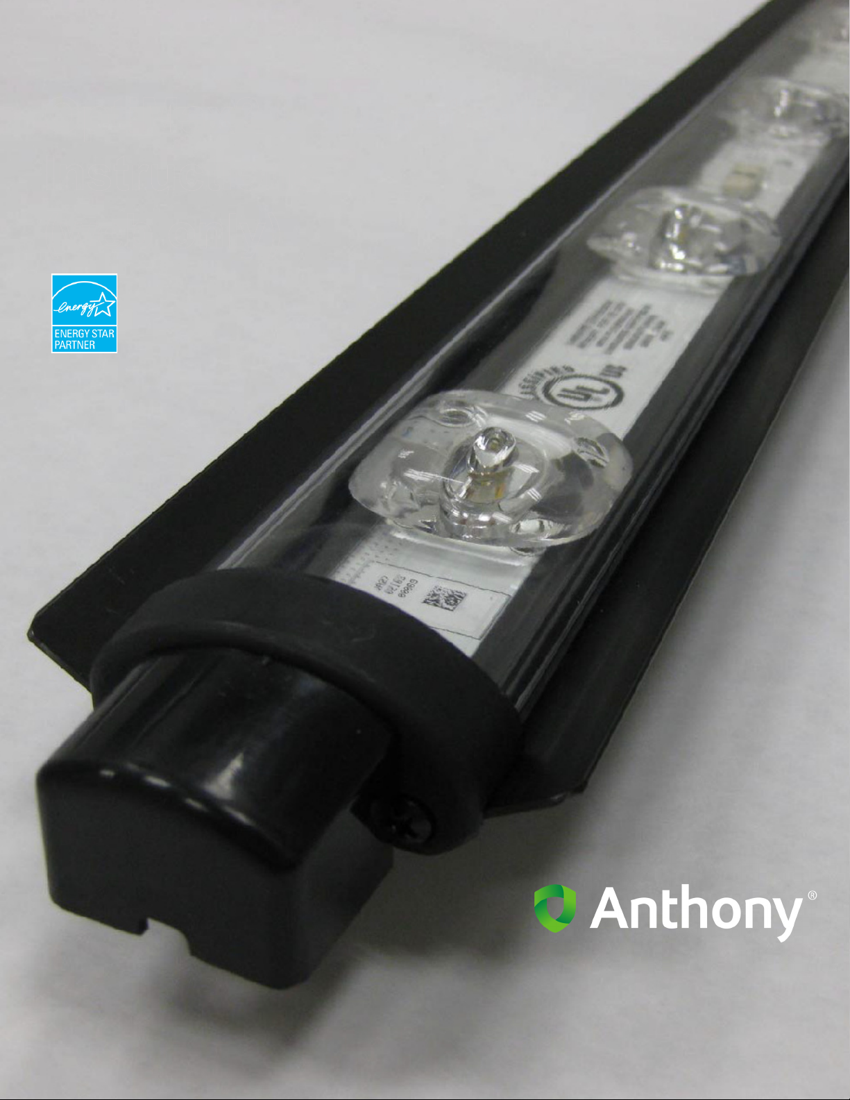
OptiMax2 LED Retrofit
Instructions
(web only)
99-18258-I001_A
Page 2
Document Revision History
Revision History
Version Date Revised by Comments
Rev A 18 May 2010 SWatstein New release. Replace individual LED retrofit manual.
Contributors
Name Name Name Name
Sherman Watstein
Frank Carbajal
Harvey Tsui
Copyright © 2010 by
ALL rights reserved. Information in this document is subject to change without notice. Companies, names and data used in examples
herein are fictitious unless otherwise noted. No part of this document may be reproduced or transmitted in any form or by any means,
electronic or mechanical, for any purpose, without express permission of Anthony Manufacturing Co., Inc.
12391 Montero Street, Sylmar, CA 91342
800.772.0900 www.anthonyintl.com
99-18258-I001_A
Page 3

Table of Contents
Table of Contents
WARNINGS AND IMPORTANT NOTES ........................................................................................................ 1
Safety ..................................................................................................................................................... 1
Tools....................................................................................................................................................... 2
TIPS........................................................................................................................................................ 2
RETROFIT LED COMPONENTS ....................................................................................................................3
ADDITIONAL PARTS REQUIRED FOR Ardco FRAME ............................................................................... 5
ADDITIONAL PARTS REQUIRED FOR MODELS 1001, 401, 1KDR/1KDB, 401D/401B ............................ 5
REMOVING EXISTING LIGHTING SYSTEM ................................................................................................. 6
Removing Existing Lighting System: ...................................................................................................... 6
Locate, Drill and Mount Clip Mounting Fixtures For Center Mullion ....................................................... 7
ORIENTATION OF CENTER FIXTURES ....................................................................................................... 8
Center Mullion LED Fixture Mounting Instructions ................................................................................. 8
Locking LED Fixture to Center Mullion Fixture....................................................................................... 8
END MULLION FIXTURE ............................................................................................................................. 10
Removing Existing Lighting System ..................................................................................................... 10
Locate, Drill and Mount the LED Fixture Mounting Clip For End Mullion ............................................. 10
Orientation Of End Fixtures .................................................................................................................. 11
End Mullion LED Fixture Mounting Instructions.................................................................................... 11
Locking LED Fixture to Right End Mullion Fixture (Wires Connected at Bottom of Frame) ................. 12
Locking LED Fixture to Left End Mullion Fixture (Wires Connected at Top of Frame)......................... 13
OptiMax2 RETROFIT INSTRUCTIONS FOR
ANTHONY MODEL 401D AND 1KDR .......................................................................................................... 14
Removing Existing Lighting System ..................................................................................................... 14
Locate, Drill and Mount the Top and Bottom LED Fixture
Mounting Clips on Center Mullion (Model 401) .................................................................................... 14
Center Mullion LED Fixture Mounting Instructions ............................................................................... 16
Locate, Drill and Mount the Top and Bottom LED Fixture Mounting Clips for End Mullion .................. 17
End Mullion LED Fixture Mounting Instructions.................................................................................... 19
Locking LED Fixture to Center Mullion Fixture..................................................................................... 20
Locate, Drill and Mount the Top and Bottom LED Fixture Mounting Clips for Center Mullion.............. 21
Connecting LED Light Fixture to Wire Plug Assembly ......................................................................... 23
Ardco FRAMES ............................................................................................................................................ 24
Typical Orientations.............................................................................................................................. 24
Parts Removal ...................................................................................................................................... 24
HUSSMANN FRAME .................................................................................................................................... 26
Removing Existing Lighting System ..................................................................................................... 26
Locate, Drill and Mount the LED Fixture Mounting Clips for Hussmann Frame................................... 26
End Mullion Fixture LED Mounting Instructions.................................................................................... 27
CONNECTING THE WIRE PLUG ASSEMBLY TO THE
LED FIXTURE WIRES .................................................................................................................................. 28
Connecting Wires at the Bottom of the Frame ..................................................................................... 28
Connecting Wires at the Top of the Frame........................................................................................... 28
MOUNTING THE LED POWER SUPPLIES ................................................................................................. 30
Low Power (3-in-1 Driver)..................................................................................................................... 30
Low and High Power ............................................................................................................................ 31
Table 1 Fixture Orientation ......................................................................................................................... 32
ORIENTATION OF CENTER FIXTURES ................................................................................................
STANDARD CONFIGURATION ................................................................................................................... 36
TYPICAL INSTALLATION (HALF POWER END FIXTURES WITH SINGLE FIXTURE DRIVERS) ....36
5/18/2010 i 99-18258-I001_A
..... 34
Page 4

Table of Contents
STANDARD CONFIGURATION (1-Door) ............................................................................................ 36
STANDARD CONFIGURATION (2-Door) ............................................................................................ 36
STANDARD CONFIGURATION (3-Door) ............................................................................................ 37
Standard Configuration (4-Door) .......................................................................................................... 37
(Standard Configuration (5-Door) ......................................................................................................... 37
STANDARD CONFIGURATION (6-Door) ............................................................................................ 38
OPTIONAL CONFIGURATION (FULL POWER ENDS) ...................................................................... 38
FULL POWER ENDS OPTION ............................................................................................................ 38
FULL POWER End Option (1-Door) .................................................................................................... 39
FULL POWER End & MULL Option (2-Door) ...................................................................................... 39
FULL POWER End & MULL Option (3-Door) ...................................................................................... 39
CONFIGURATION (MULTI-FIXTURE DRIVER) .................................................................................. 40
TYPICAL INSTALLATION (4-Dr Frame Shown, 3-in-1 Driver) ............................................................ 40
HALF POWER End Options (3-in-1, Driver 1-Door) ............................................................................ 40
HALF POWER End & MULL Options (3-in-1 Drive, 2-Door) ................................................................ 40
HALF POWER End & MULL Options (3-in-1 Driver, 4-Door) .............................................................. 41
HALF POWER End & MULL Options (3-in-1 Driver, 5-Door) .............................................................. 41
HALF POWER End & MULL Options (6-Door) .................................................................................... 41
3-Door (Upper Raceway) ..................................................................................................................... 42
MULLION CONFIGURATIONS .....................................................................................................................44
LED CLEANING INSTRUCTIONS ................................................................................................................46
5/18/2010 ii 99-18258-I001_A
Page 5
WARNINGS AND IMPORTANT NOTES
WARNINGS AND IMPORTANT NOTES
BEFORE YOU BEGIN
Read these instructions completely and carefully.
WARNING: TO REDUCE THE RISK OF FIRE, ELECTRICAL SHOCK OR INJURY,
OBSERVE THE FOLLOWING:
1. INSTALLATION OF THIS RETROFIT ASSEMBLY REQUIRES A PERSON FAMILIAR WITH THE CONSTRUCTION AND OPERATION OF ELECTRICAL SYSTEMS AND THE HAZARD INVOLVED.
2. Use this unit in the manner intended by the manufacturer.
3. Before servicing or cleaning, switch power off.
4. Turn power off before removing existing lighting system and follow appropriate lock out/tag out safety procedures.
5. For use in a commercial refrigeration case with packaged foods only.
6. When drilling for installation hardware, be careful not to nick wires or electrical components which may result in risk
of fire or electrical shock.
7. Only those open holes indicated in the photographs and/or drawings may be made or altered as a result of kit
installation. Do not leave any other open holes in an enclosure of wiring or electrical components
8. Risk of fire or electrical shock. Install this kit only in the luminaries that has the construction features shown in the
photographs and/or drawings.
9. To prevent wiring damage or abrasion, do not expose wiring to edges of sheet metal or other sharp objects.
NOTE: Remove and dispose of existing ballasts per any local or Federal guidelines.
Safety
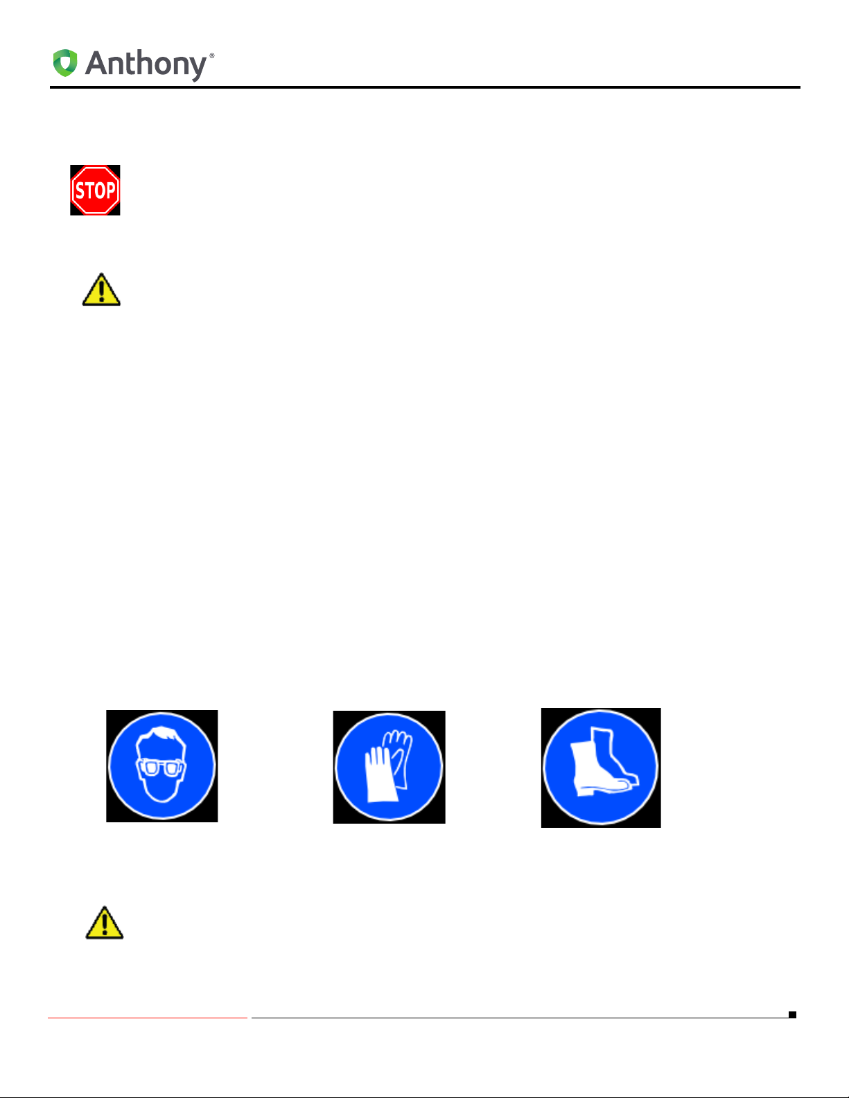
Proper safety equipment includes:
safety glasses
TURN OFF ALL ELECTRICAL POWER PRIOR TO BEGINNING WORK ON THE
DOOR OR ON ANY ELECTRICAL. USE EXTRA CAUTION WHEN WORKING WITH
OR AROUND THE DOOR GLASS PACKAGE.
work gloves
work shoes
5/18/2010 1 99-18258-I001_A
Page 6
WARNINGS AND IMPORTANT NOTES
Tools
Tools required for this procedure include:
#2 Phillips-head screwdriver Rubber or plastic mallet
Cordless drill w/attachments Flat-head screwdriver
Needle-nose pliers Wire stripper and cutter
Razor Knife Tape measure
TIPS
• Always use the correct tool for the job to be performed. This ensures proper installation and minimizes safety
risks.
• If there is any doubt about the work to be performed, consult with a certified technician or Anthony
representative.
• Preventative maintenance is recommended to ensure product longevity.
5/18/2010 2 99-18258-I001_A
Page 7
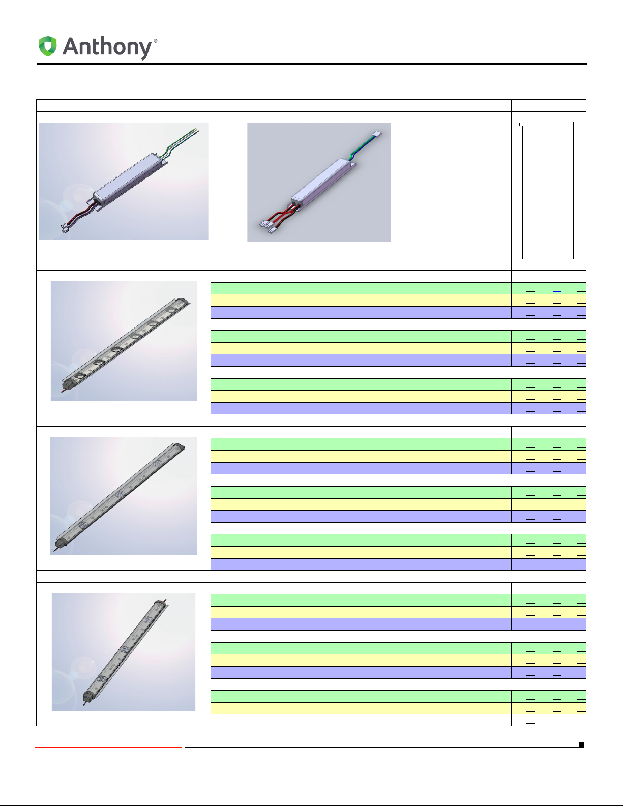
LED Power Supply Part No.
RETROFIT LED COMPONENTS
RETROFIT LED COMPONENTS
1
2
1
60-16979-0002
1
or 60-16851-0002
1
60-17544-0001
2
60-16979-0002 - 500 ma, Low Power
60-16851-0002 - 700 ma, High Power
60-17544-0001 - 500 ma, Multi-Fixture
Center Fixture Part No. Description Color Temp (K)
60-17447-0001 60” Light Fixture 4100
60-17447-0002 72” Light Fixture 4100
60-17447-0003 48” Light Fixture 4100
60-17447-1001 60” Light Fixture 5000
60-17447-1002 72” Light Fixture 5000
60-17447-1003 48” Light Fixture 5000
60-17447-2001 60” Light Fixture 3500
60-17447-2002 72” Light Fixture 3500
60-17447-2003 48” Light Fixture 3500
HALF POWER END
Right End Fixture Part No. Description Color Temp (K)
60-17445-0001 60” Light Fixture 4100
60-17445-0002 72” Light Fixture 4100
60-17445-0003 48” Light Fixture 4100
60-17445-1001 60” Light Fixture 5000
60-17445-1002 72” Light Fixture 5000
60-17445-1003 48” Light Fixture 5000
60-17445-2001 60” Light Fixture 3500
60-17445-2002 72” Light Fixture 3500
60-17445-2003 48” Light Fixture 3500
HALF POWER END
Left End Fixture Part No. Description Color Temp (K)
60-17446-0001 60” Light Fixture 4100
60-17446-0002 72” Light Fixture 4100
60-17446-0003 48” Light Fixture 4100
60-17446-1001 60” Light Fixture 5000
60-17446-1002 72” Light Fixture 5000
60-17446-1003 48” Light Fixture 5000
60-17446-2001 60” Light Fixture 3500
60-17446-2002 72” Light Fixture 3500
60-17446-2003 48” Light Fixture 3500
5/18/2010 3 99-18258-I001_A
Page 8
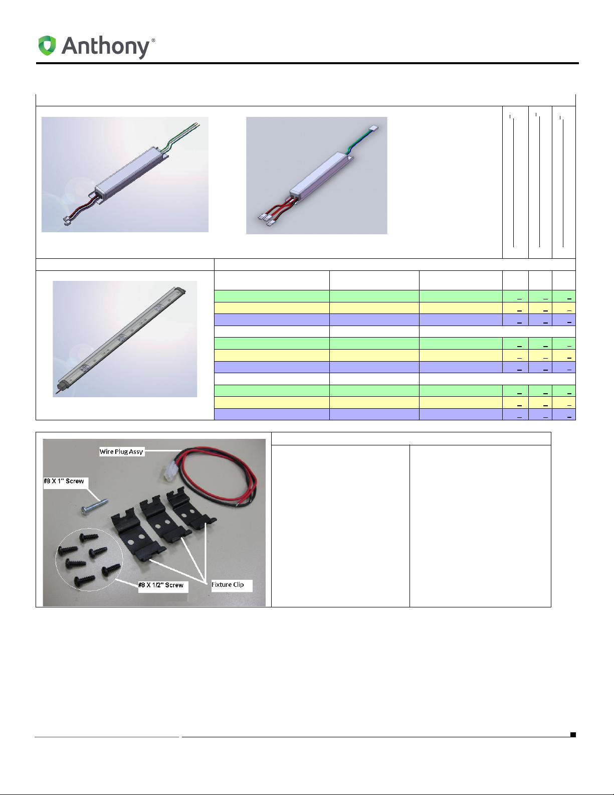
LED Power Supply Part No.
RETROFIT LED COMPONENTS
1
2
60-16979-0002
1
or 60-16851-0002
1
60-17544-0001
2
60-16979-0002 - 500 ma, Low Power160-16851-0002 - 700 ma, High Power
60-17544-0001 - 500 ma, Multi-Fixture
Full POWER END
Right End Fixture Part
No.
60-17554-0001 60” Light Fixture 4100 x x
60-17554-0002 72” Light Fixture 4100 x x
60-17554-0003 48” Light Fixture 4100 x x
60-17554-1001 60” Light Fixture 5000 x x
60-17554-1002 72” Light Fixture 5000 x x
60-17554-1003 48” Light Fixture 5000 x x
60-17554-2001 60” Light Fixture 3500 x x
60-17554-2002 72” Light Fixture 3500 x x
60-17554-2003 48” Light Fixture 3500 x x
Mounting Kit Part No.
04-18201-0001 OptiMax2 Mounting Kit
Description Color Temp (K)
x
x
x
x
x
x
x
x
x
5/18/2010 4 99-18258-I001_A
Page 9
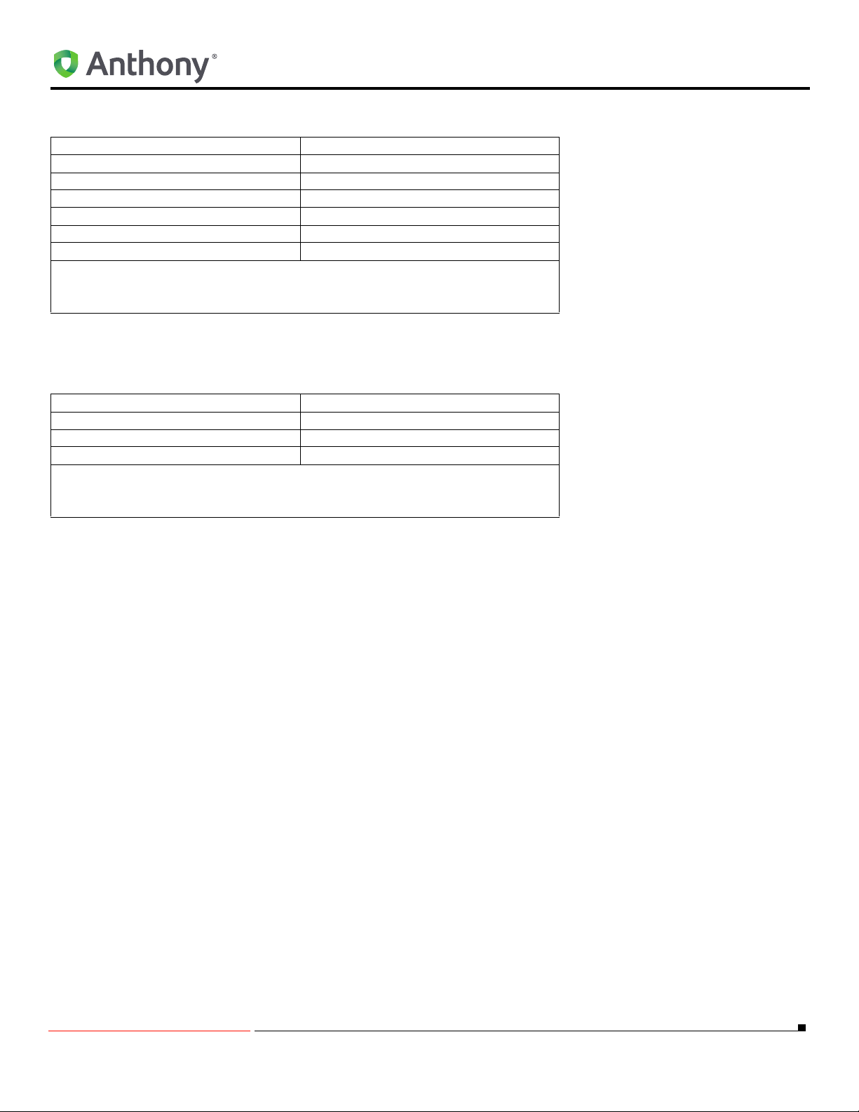
ADDITIONAL PARTS REQUIRED FOR Ardco FRAME
ADDITIONAL PARTS REQUIRED FOR Ardco FRAME
Part Number Description
15-12314-0001 UL approved enclosure
40-12348-1002 #8/32 zinc nuts
40-10997-1005 #8-32 X 3/8” screws
40-11012-1007 #10X 1/2” hex screw with washers
70-13705-0001 #1/32” thick foam sealant tape
77-12036P018 #10-32 hex nuts
NOTE:1 The OptiMax2 lamp assemblies are available from Anthony Inc. Specify the lamp length and
color temperature required when ordering LED lamp assemblies.
Items listed must be ordered before retrofiting the Ardco frame.
ADDITIONAL PARTS REQUIRED FOR MODELS 1001, 401, 1KDR/1KDB,
401D/401B
Part Number Description
40-12348-1002 #8/32 zinc nuts
40-10997-1005 #8-32 X 3/8” screws
70-13705-0001 #1/32” thick foam sealant tape
NOTE:1 The OptiMax2 lamp assemblies are available from Anthony Inc. Specify the lamp length and
color temperature required when ordering LED lamp assemblies.
Items listed must be ordered before retrofiting the model 1001, 401, 1KDR/1KDB or 401D/401B.
5/18/2010 5 99-18258-I001_A
Page 10

REMOVING EXISTING LIGHTING SYSTEM
REMOVING EXISTING LIGHTING SYSTEM
Removing Existing Lighting System:
1. Remove the following items:
a. Lens
b. Fluorescent lamps
c. Lamp holder
d. Mounting clips
e. Ballasts from existing lighting system
2. For Anthony 401D and 1KDR with ELS option only:
a. Remove Mullion cover using a flat screwdriver.
b. Remove the raceway cover by inserting a flat screwdriver into the seam between the metal raceway and the
plastic cover and pry open.
NOTE: Refer to case manufactures instructions for any questions on removing the fluorescent
system and ballast.
3. Seal any open holes on Mullion using neutral cure silicone sealant (not provided).
4. Make sure you save the two #8 tapping screws used to hold the ballast.
5/18/2010 6 99-18258-I001_A
Page 11
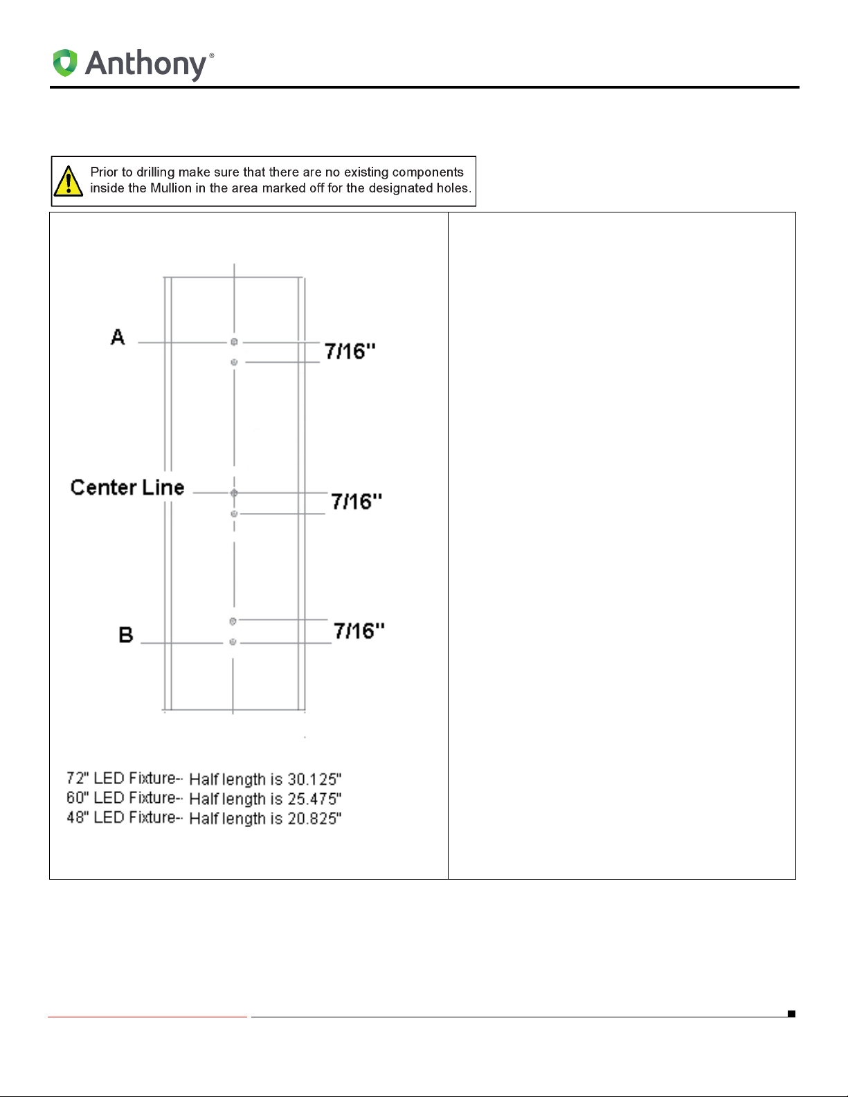
Locate, Drill and Mount Clip Mounting Fixtures For Center Mullion
1. Using a ruller measure the total width of the
Mullion and mark a vertical line half the total
width near the top and bottom of the Mullion.
2. Mark a vertical line from the top of the Mullion
to the bottom of the Mullion thru the lines measurement in step 1.
3. Divide the vertical line distance in half and
mark as a Center Line.
4. Mark a horizontal line 7/16” (0.438”) below the
center line.
5. Mark two horizontal lines, one from the center
as follows:
a. For 72” fixture-- 30.125” (
and (
B) to Center line.
REMOVING EXISTING LIGHTING SYSTEM
A) to Center Line
b. For 60” fixture-- 25.475” (
and (
B) to Center Line.
c. For 48” fixture-- 20.825” (
and (
B) to Center Line.
6. Mark one horizontal line 7/16” (0.438”) below
the line (
7. Mark one horizontal line 7/16” (0.438”) above
the line (
8. Position the center punch directly over at the
intersection of the horizontal lines (6 total) and
the vertical line (top, center and bottom) and
establish a dimple.
9. Use a power drill and (#29) 0.136” dia. drill bit,
drill (6) holes at the intersection of the vertical
center line and the horizontal lines.
10. Using a Phillips screw driver, tread the the two
#8 tapping screws (supplied) to hold each
mounting clip. A total of (6) screws and (3)
mounting clips should be installed.
11. Go to ORIENTATION OF CENTER FIXTURES
on page 8.
A).
B).
A) to Center Line
A) to Center Line
5/18/2010 7 99-18258-I001_A
Page 12
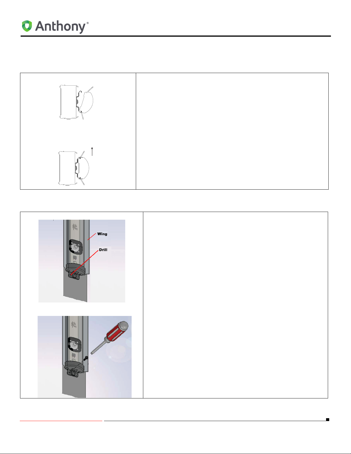
ORIENTATION OF CENTER FIXTURES
Light
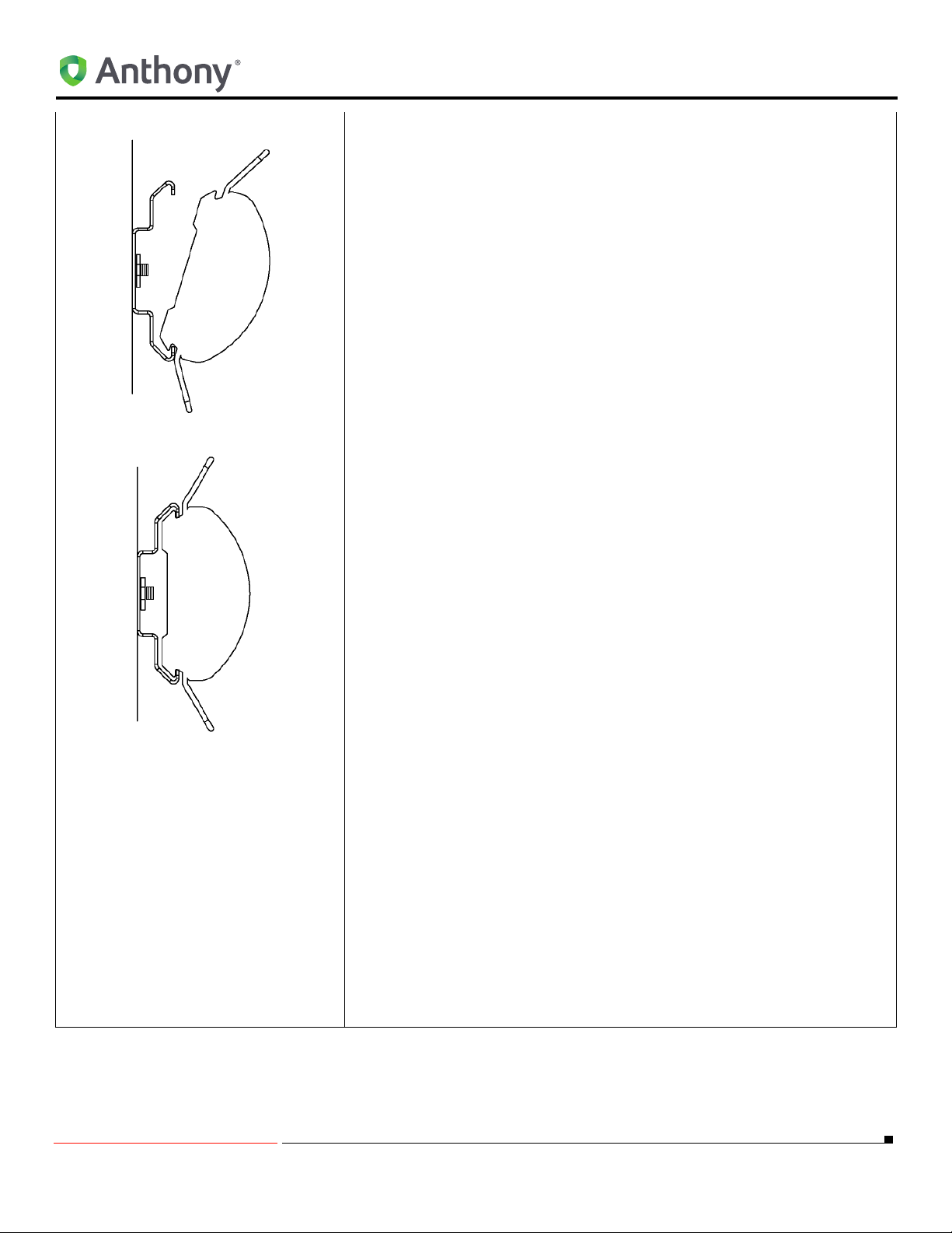
Center Mullion LED Fixture Mounting Instructions
1. Align the LED light with the mounting clips so that the LEDs are
facing the display case interior. Snap the LED light into the mounting clips:
a. By placing one edge of the LED light into the groove.
b. Gently rotate until the opposite edge firmly locks into the
NOTE: Ensure that the mounting clips lock into the outer
edge of the LED light aluminum extrusion.
c. Adjust the lamp position until it is centered on the Mullion.
2. Go to Locking LED Fixture to Center Mullion Fixture on page 8.
mounting clip
ORIENTATION OF CENTER FIXTURES
Locking LED Fixture to Center Mullion Fixture
1. Using a (#29) 0.136 dia. drill bit, drill a hole through the LED
Lighting fixture end cap and through the Center Mullion Fixture.
2. Using a Phillips screw driver to start threading the #8 X 1” long
self-tapping screw to hold the end cap to the Center Mullion.
3. Continue to “CONNECTING THE WIRE PLUG ASSEMBLY TO
THE LED FIXTURE WIRES" on page 28.
5/18/2010 8 99-18258-I001_A
Page 13

ORIENTATION OF CENTER FIXTURES
5/18/2010 9 99-18258-I001_A
Page 14
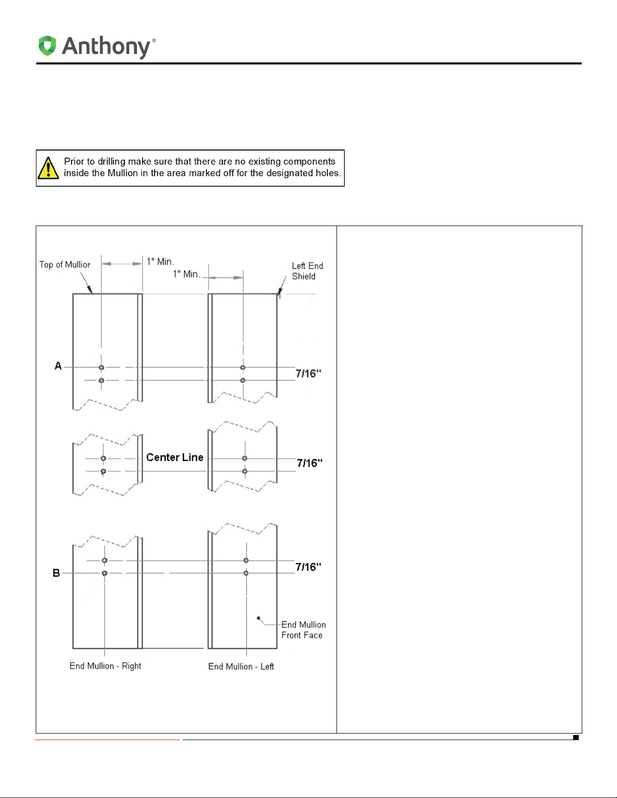
END MULLION FIXTURE
Removing Existing Lighting System
Refer to "Removing Existing Lighting System:" on page 6.
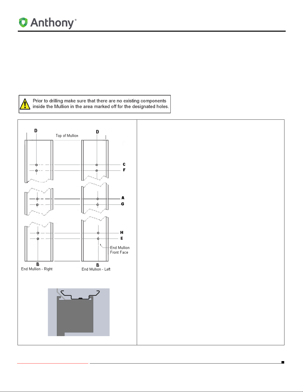
Locate, Drill and Mount the LED Fixture Mounting Clip For End Mullion
1. Using a ruller measure 1” min. from the inside
of the end Mullion exclusion at the top and
bottom.
2. Mark a vertical line from the top of the Mullion
to the bottom of the Mullion thru the lines
measurement in step 1.
3. Divide the vertical line distance in half and
mark as a center line.
4. Mark a horizontal line 7/16” (0.438”) below
the Center Line (
5. Mark two horizontal lines, one from the center (
A) as follows:
a. For 72” fixture-- 30.125” (
and (
A).
B) to Center Line.
END MULLION FIXTURE
A) to Center Line
b. For 60” fixture-- 25.475” (
Line and (
c. For 48” fixture-- 20.825” (
Line and (
6. Mark one horizontal line 7/16” (0.438”) below
the line (
7. Mark one horizontal line (H) 7/16” (0.438”)
above the line (
8. Position the center punch directly over at the
intersection of the horizontal lines (6 total)
and the vertical line (top, center and bottom)
and establish a dimple.
9. Use A power drill and (#29) 0.136” dia. drill
bit, drill (6) holes at the intersection of the
vertical center line and the horizontal lines.
10. Repeat step 1. thru step 9.for the opposite
side end Mullion.
11. Using a Phillips screw driver, tread the two #8
tapping screws (supplied) to hold each
mounting clip. A total of (6) screws and (3)
mounting clips should be installed per
Mullion.
12. Go to Orientation Of End Fixtures on page
11.
B) to Center Line.
B) to Center Line.
A).
B).
A) to Center
A) to Center
5/18/2010 10 99-18258-I001_A
Page 15
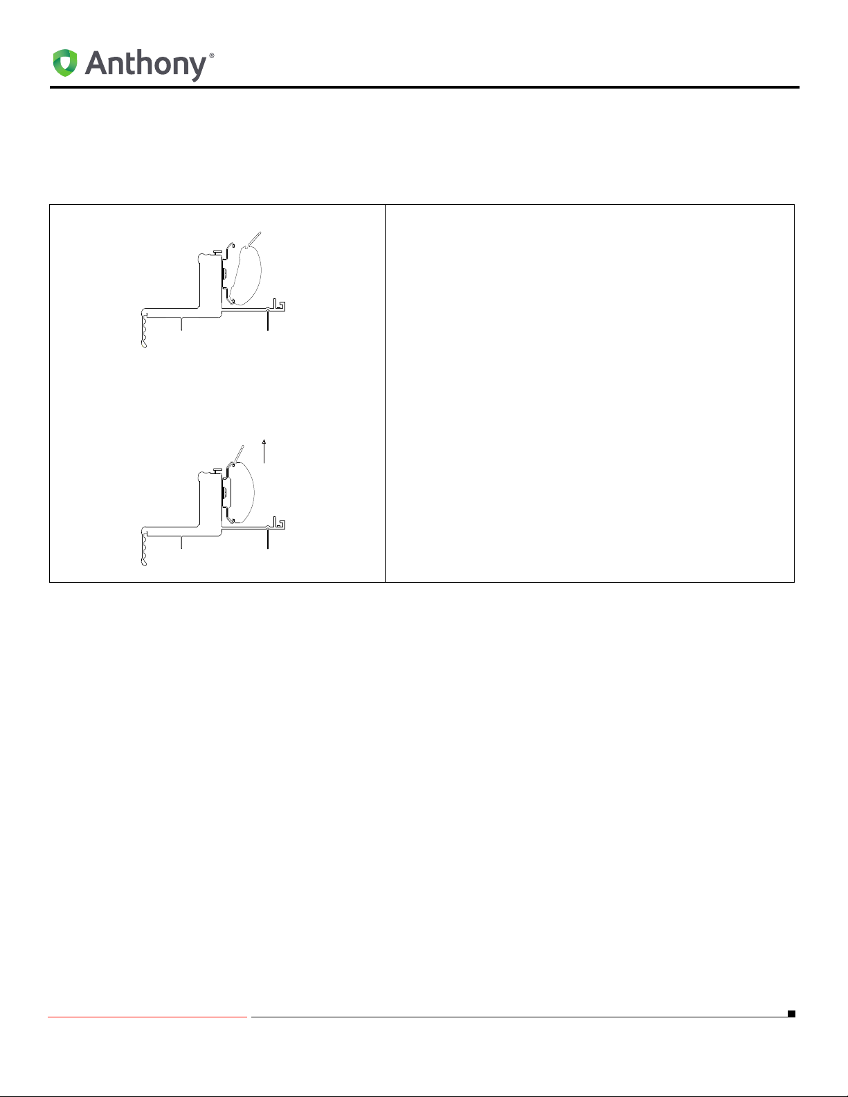
Orientation Of End Fixtures
Light
Refer to Orientation Of End Fixtures.
End Mullion LED Fixture Mounting Instructions
END MULLION FIXTURE
1. Align the LED light with the mounting clips so that the
LEDs are facing the display case interior. Snap the LED
light into the mounting clips:
a. By placing one edge of the LED light into the groove.
b. Gently rotate until the opposite edge firmly locks into
the mounting clip.
NOTE: Ensure that the mounting clips lock into the
outer edge of the LED light aluminum extrusion.
c. Adjust the LED lamp assembly until it is centered on
the Mullion.
2. Go to Locking LED Fixture to Right End Mullion Fixture
(Wires Connected at Bottom of Frame) on page 12 or go
to “Locking LED Fixture to Left End Mullion Fixture
(Wires Connected at Top of Frame) on page 13.
5/18/2010 11 99-18258-I001_A
Page 16
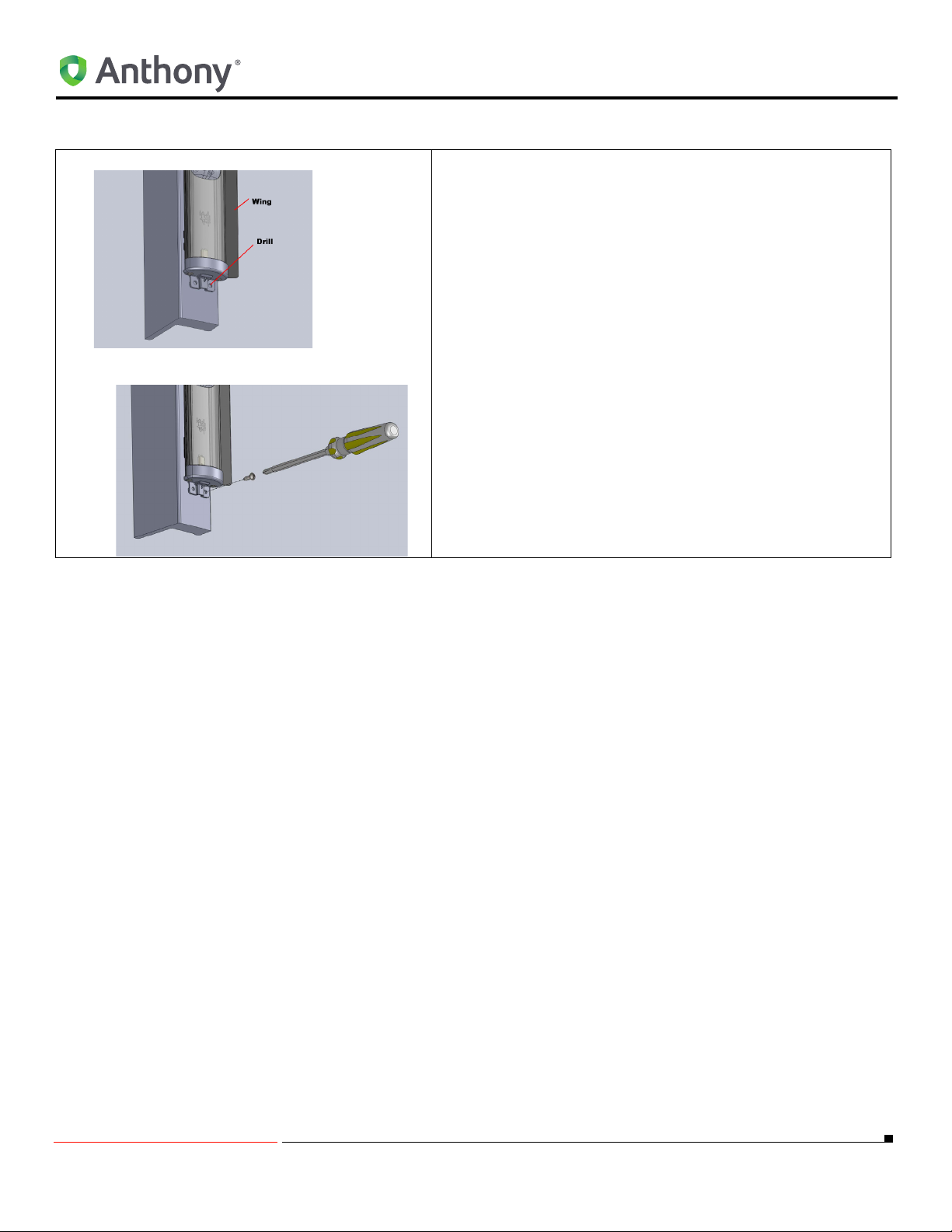
Locking LED Fixture to Right End Mullion Fixture (Wires Connected at Bottom of Frame)
1. Using a (#29) 0.136 dia. drill bit, drill a hole through the
LED Lighting fixture end cap and through the End Mullion
Fixture.
2. Using a Phillips screw driver to start threading the #8 X 1”
long self-tapping screw to hold the clip to the End Mullion
fixture.
3. Continue to “CONNECTING THE WIRE PLUG
ASSEMBLY TO THE LED FIXTURE WIRES" on page
28.
END MULLION FIXTURE
5/18/2010 12 99-18258-I001_A
Page 17
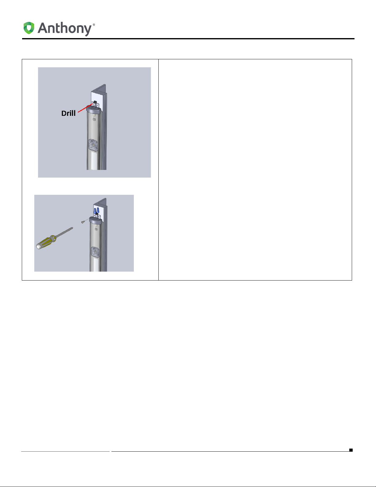
Locking LED Fixture to Left End Mullion Fixture (Wires Connected at Top of Frame)
1. Using a (#29) 0.136 dia. drill bit, drill a hole through the LED
Lighting fixture through the end cap and End Mullion Fixture.
2. Using a Phillips screw driver to start threading the #8 X 1”
long self-tapping screw to hold the end cap to the End
Mullion.
3. Continue to “CONNECTING THE WIRE PLUG ASSEMBLY
TO THE LED FIXTURE WIRES" on page 28
END MULLION FIXTURE
5/18/2010 13 99-18258-I001_A
Page 18
OptiMax2 RETROFIT INSTRUCTIONS FOR ANTHONY MODEL 401D AND 1KDR
OptiMax2 RETROFIT INSTRUCTIONS FOR
ANTHONY MODEL 401D AND 1KDR
Removing Existing Lighting System
Refer to "Removing Existing Lighting System:" on page 6.
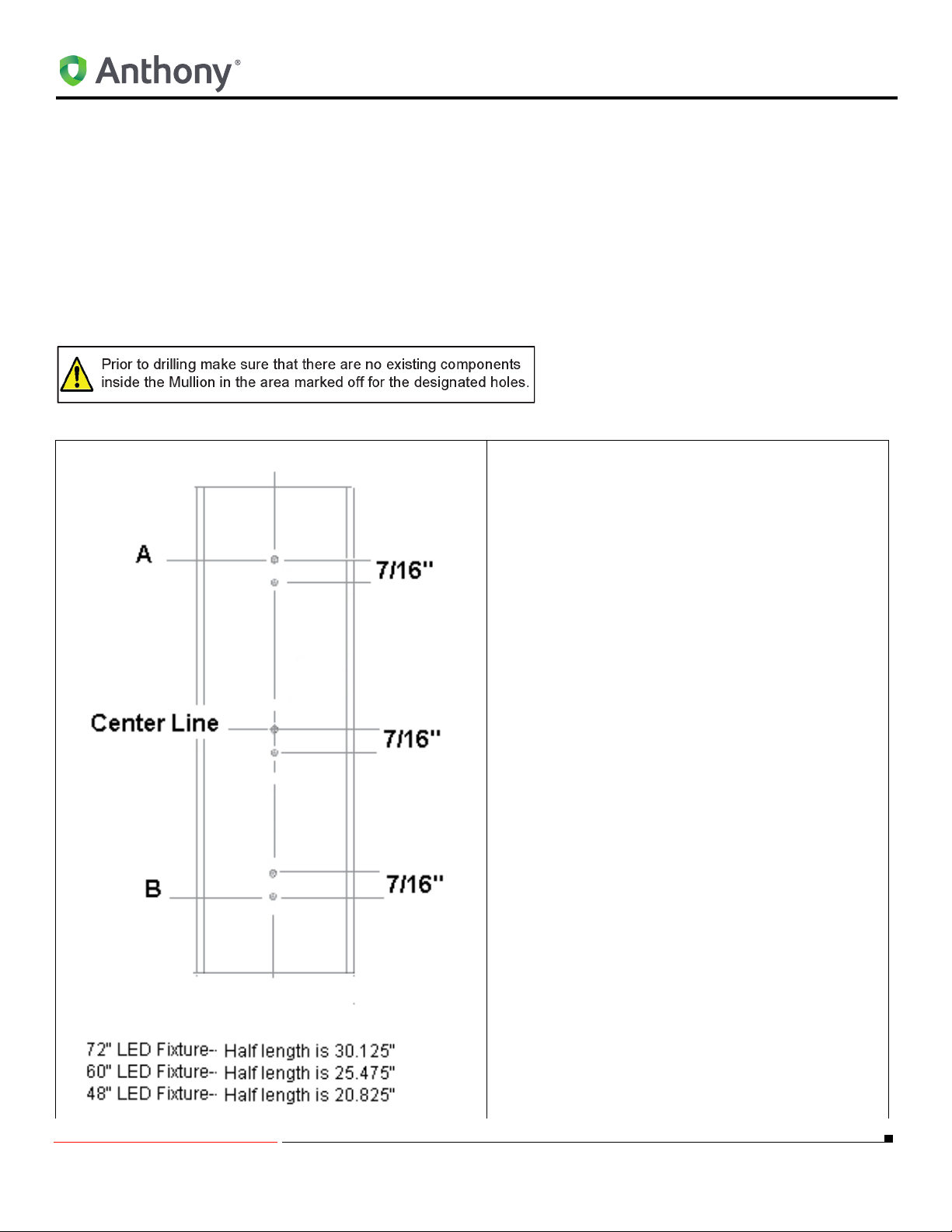
Locate, Drill and Mount the Top and Bottom LED Fixture Mounting Clips on Center Mullion (Model 401)
NOTE: Refer to
"Fixture Orientation" on page 32 for
the following procedures:
1. Using a ruller measure the total width of the Mullion and mark a vertical line half the total width
near the top and bottom of the Mullion.
2. Mark a vertical line from the top of the Mullion to
the bottom of the Mullion thru the lines measurement in step 1.
3. Divide the vertical line distance in half and mark
as a Center Line.
4. Mark a horizontal line 7/16” (0.438”) below the
center line.
5. Mark two horizontal lines, one from the center as
follows:
a. For 72” fixture-- 30.125” (
and (
B) to Center line.
b. For 60” fixture-- 25.475” (
and (
B) to Center Line.
c. For 48” fixture-- 20.825” (
and (
B) to Center Line.
6. Mark one horizontal line 7/16” (0.438”) below the
line (
A).
7. Mark one horizontal line 7/16” (0.438”) above the
line (
B).
8. Position the center punch directly over at the
intersection of the horizontal lines (6 total) and
the vertical line (top, center and bottom) and
establish a dimple.
A) to Center Line
A) to Center Line
A) to Center Line
5/18/2010 14 99-18258-I001_A
Page 19
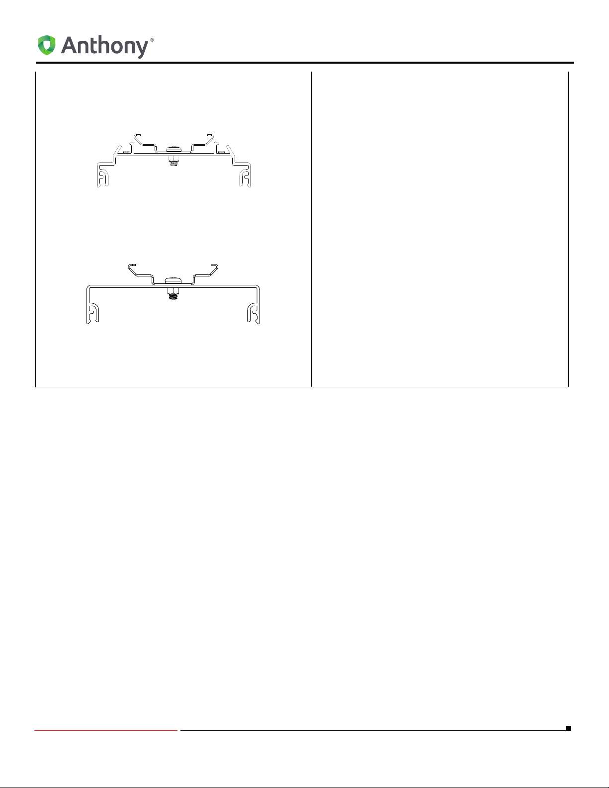
With ELS Option
OptiMax2 RETROFIT INSTRUCTIONS FOR ANTHONY MODEL 401D AND 1KDR
9. Use a power drill and (#29) 0.136” dia. drill bit,
drill (6) holes at the intersection of the vertical
center line and the horizontal lines.
10. Insert two #8-32 X 3/8” screws thru each clip
and Mullion cover and secure with two #8-32
captive nuts. A total of (6) screws, (3) nuts, and
(3) mounting clips should be installed.
11. Drill a 3/8” hole about 1/2” from the top of the
installed LED mounting clip.
NOTE: 3/8” hole will be used for bring the
leads from the wire plug assembly to the LED
fixture.
12. Go to Center Mullion LED Fixture Mounting
Instructions on page 16.
With T-10 Option
5/18/2010 15 99-18258-I001_A
Page 20
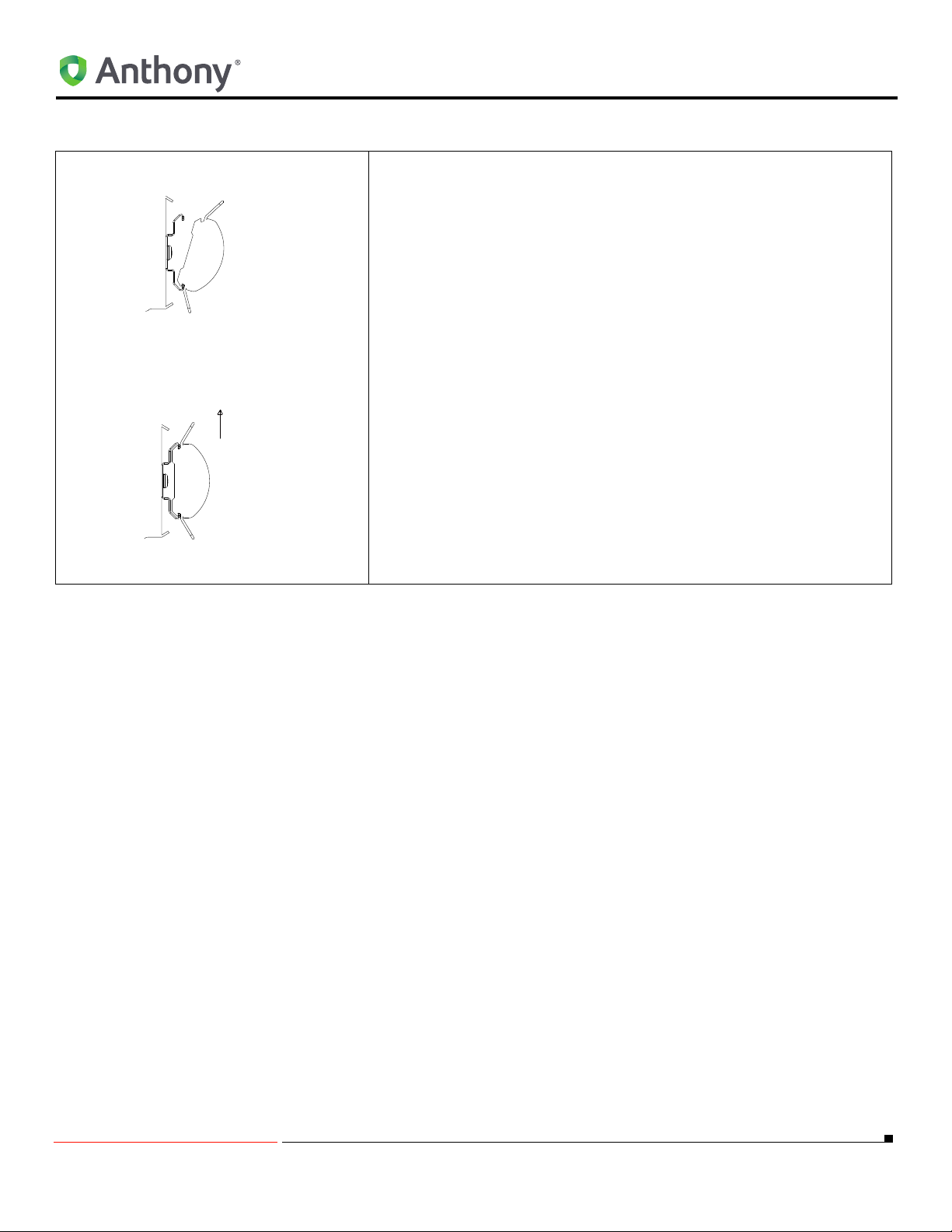
Center Mullion LED Fixture Mounting Instructions
Light
1. Align the LED light with the mounting clips so that the LEDs are
facing the display case interior. Snap the LED light into the mounting clips:
a. By placing one edge of the LED light into the groove.
b. Gently rotate until the opposite edge firmly locks into the
NOTE: Ensure that the mounting clips lock into the outer
edge of the LED light aluminum extrusion.
c. Adjust the lamp position until it is centered on the Mullion.
2. Continue to “Locking LED Fixture to Center Mullion Fixture" on
page 8.
OptiMax2 RETROFIT INSTRUCTIONS FOR ANTHONY MODEL 401D AND 1KDR
mounting clip
5/18/2010 16 99-18258-I001_A
Page 21
OptiMax2 RETROFIT INSTRUCTIONS FOR ANTHONY MODEL 401D AND 1KDR
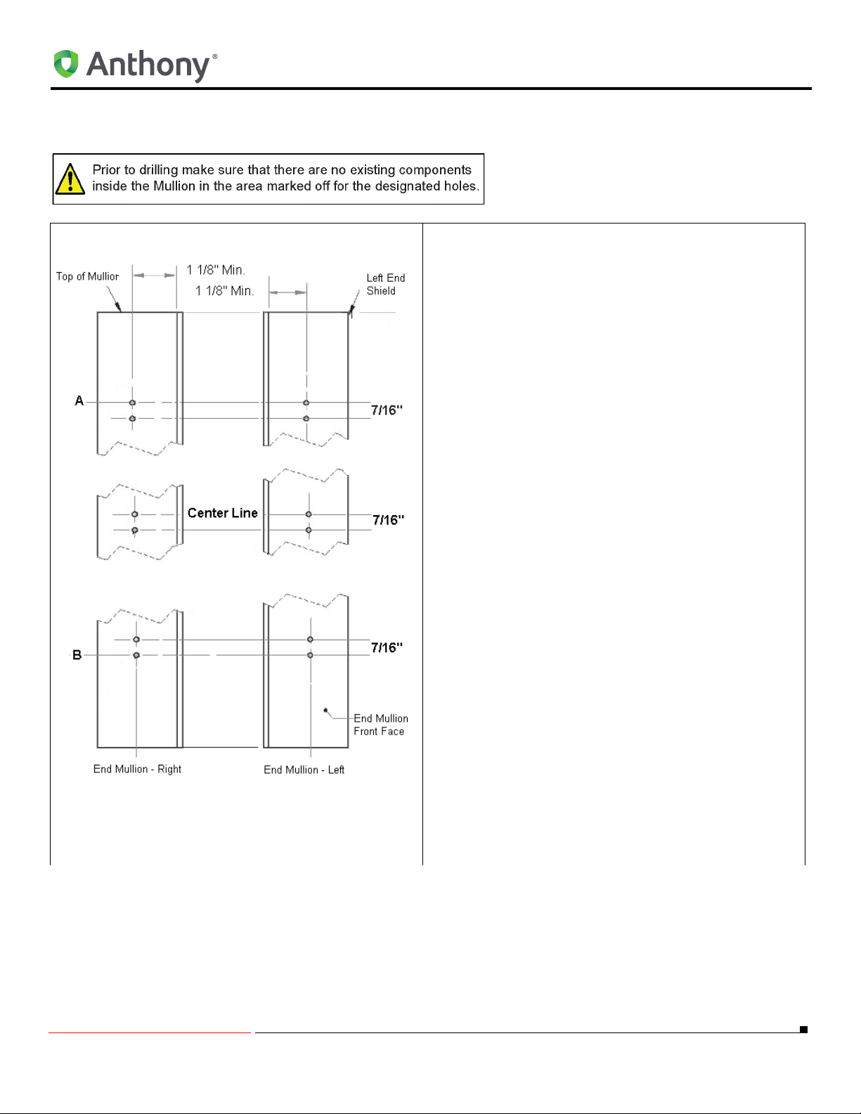
Locate, Drill and Mount the Top and Bottom LED Fixture Mounting Clips for End Mullion
NOTE: Refer to
"Fixture Orientation" on page 32 for
the following procedures:
1. Using a ruller measure 1 1/8” min. from the inside of
the end Mullion exclusion at the top and bottom.
2. Mark a vertical line from the top of the Mullion to the
bottom of the Mullion thru the lines measurement in
step 1.
3. Divide the vertical line distance in half and mark as
a center line.
4. Mark a horizontal line 7/16” (0.438”) below the Center Line (
5. Mark two horizontal lines, one from the center (
as follows:
a. For 72” fixture-- 30.125” (
b. For 60” fixture-- 25.475” (
c. For 48” fixture-- 20.825” (
6. Mark one horizontal line 7/16” (0.438”) below the
line (
7. Mark one horizontal line (H) 7/16” (0.438”) above
the line (
8. Position the center punch directly over at the intersection of the horizontal lines (6 total) and the vertical line (top, center and bottom) and establish a
dimple.
9. Use as power drill and (#29) 0.136” dia. drill bit, drill
(6) holes at the intersection of the vertical center
line and the horizontal lines.
10. Repeat step 1. thru step 9. for the opposite side end
Mullion.
A).
(
B) to Center Line.
(
B) to Center Line.
(
B) to Center Line.
A).
B).
A)
A) to Center Line and
A) to Center Line and
A) to Center Line and
5/18/2010 17 99-18258-I001_A
Page 22
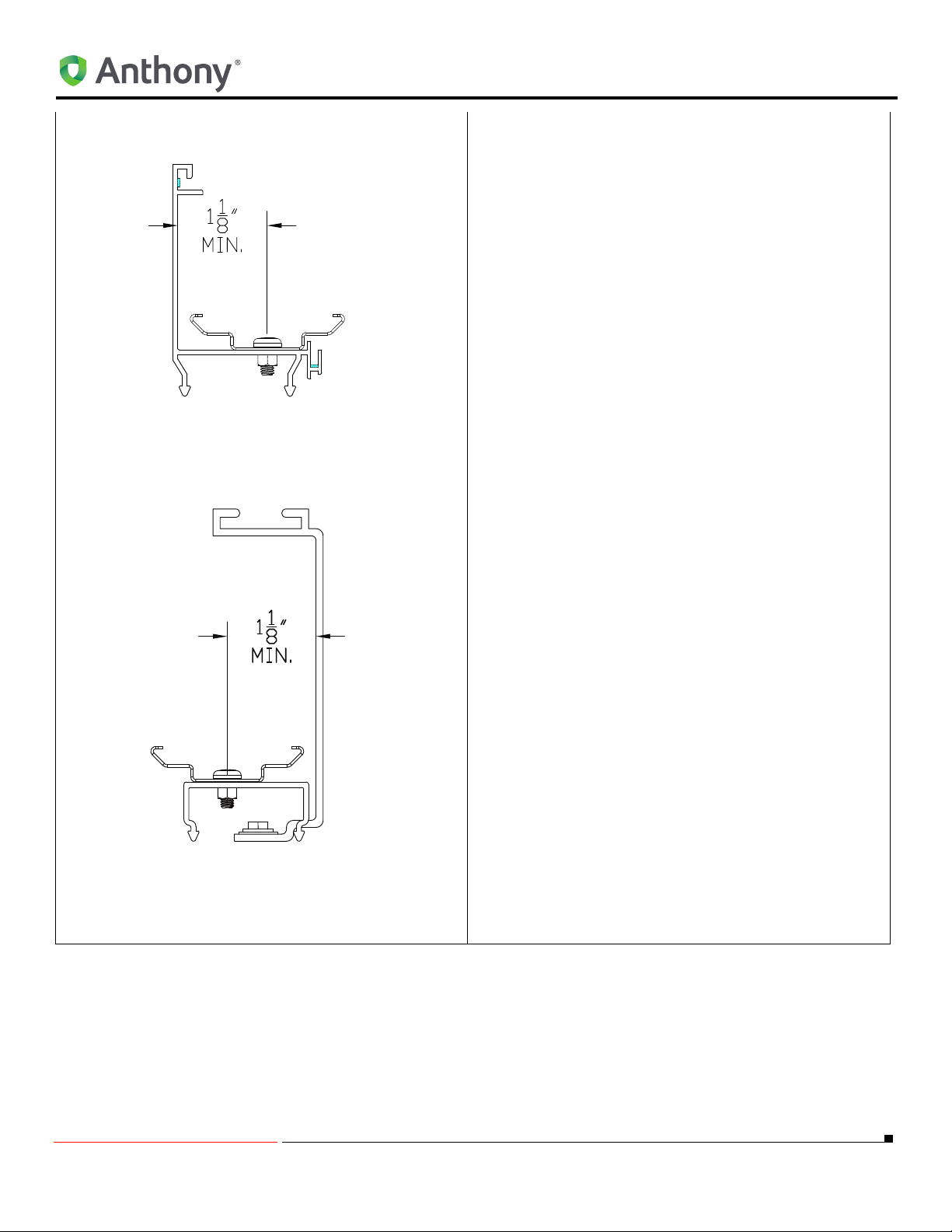
With ELS Option
OptiMax2 RETROFIT INSTRUCTIONS FOR ANTHONY MODEL 401D AND 1KDR
11. Insert two #8-32 X 3/8” screws thru each clip and
Mullion cover and secure with two #8-32 captive
nuts. A total of (6) screws, (3) nuts, and (3) mounting clips should be installed.
12. Drill a 3/8” hole about 1/2” from the top of the
installed LED mounting clip.
NOTE: 3/8” hole will be used for bring the leads
from the wire plug assembly to the LED fixture.
13. Continue to “End Mullion LED Fixture Mounting
Instructions" on page 19.
With T10 Option
5/18/2010 18 99-18258-I001_A
Page 23
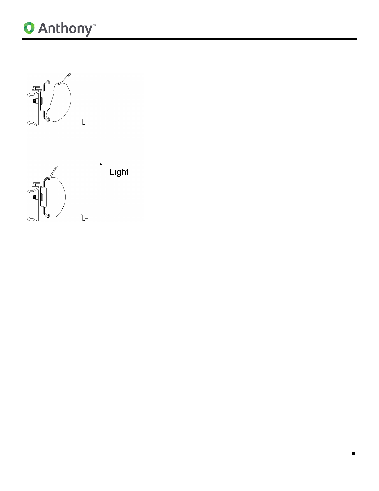
End Mullion LED Fixture Mounting Instructions
1. Align the LED light with the mounting clips so that the LEDs are
NOTE: Ensure that the mounting clips lock into the outer
edge of the LED light aluminum extrusion.
2. Continue to “Locking LED Fixture to Center Mullion Fixture" on
OptiMax2 RETROFIT INSTRUCTIONS FOR ANTHONY MODEL 401D AND 1KDR
facing the display case interior. Snap the LED light into the mounting clips:
a. By placing one edge of the LED light into the groove.
b. Gently rotate until the opposite edge firmly locks into the
mounting clip
c. Adjust the lamp position until it is centered on the Mullion.
page 20.
5/18/2010 19 99-18258-I001_A
Page 24
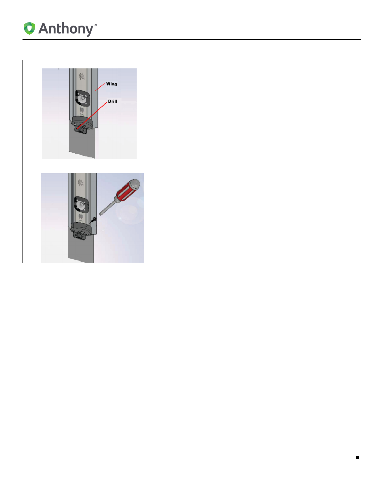
Locking LED Fixture to Center Mullion Fixture
OptiMax2 RETROFIT INSTRUCTIONS FOR ANTHONY MODEL 401D AND 1KDR
1. Using a (#29) 0.136 dia. drill bit, drill a hole through the LED
Lighting fixture end cap and through the Center Mullion Fixture.
2. Using a Phillips screw driver to start threading the #8 X 1” long
self-tapping screw to hold the end cap to the Center Mullion.
3. Continue to “CONNECTING THE WIRE PLUG ASSEMBLY TO
THE LED FIXTURE WIRES" on page 28.
5/18/2010 20 99-18258-I001_A
Page 25
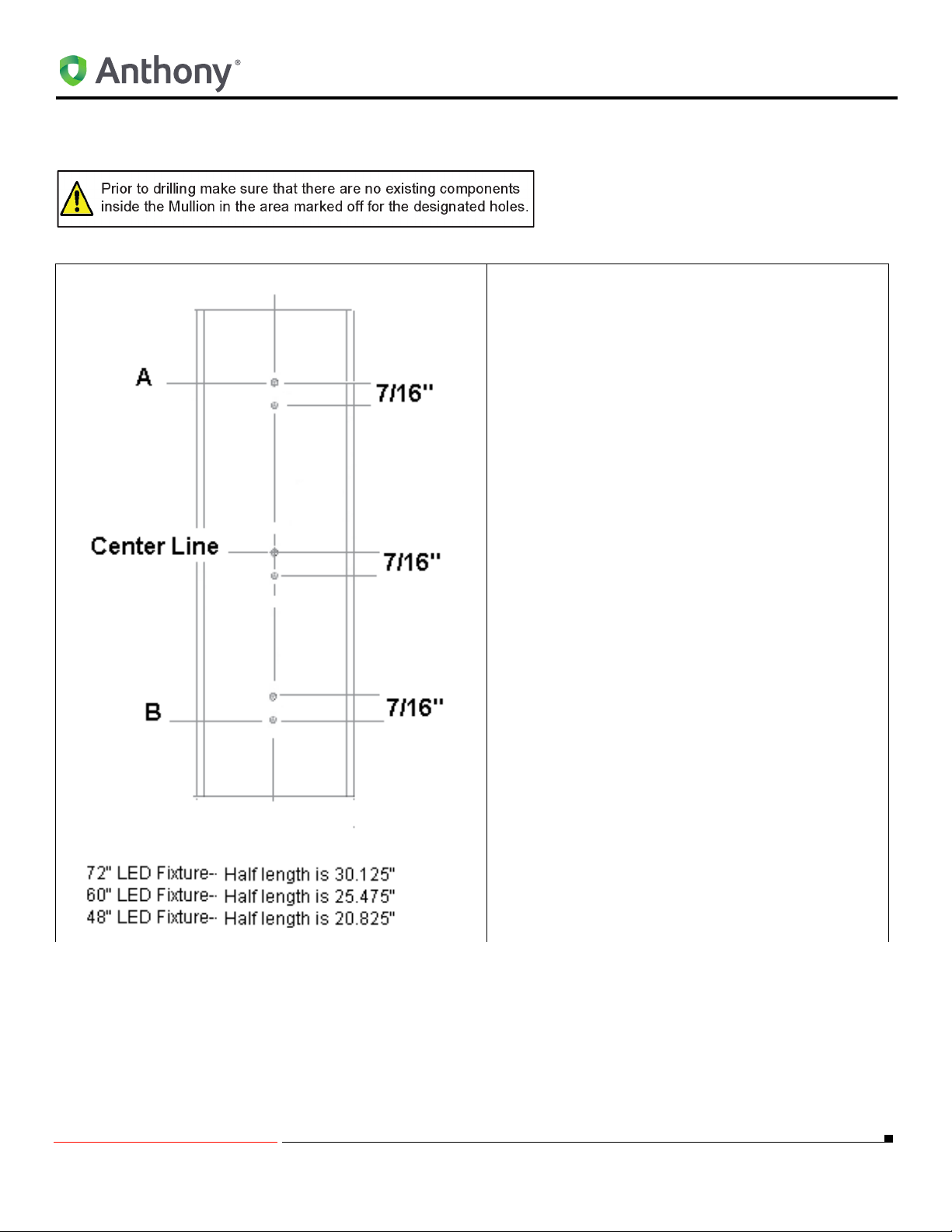
OptiMax2 RETROFIT INSTRUCTIONS FOR ANTHONY MODEL 401D AND 1KDR
Locate, Drill and Mount the Top and Bottom LED Fixture Mounting Clips for Center Mullion
NOTE: Refer to
"Fixture Orientation" on page 32 for
the following procedures:
1. Using a ruller measure the total width of the Mullion and mark a vertical line half the total width
near the top and bottom of the Mullion.
2. Mark a vertical line from the top of the Mullion to
the bottom of the Mullion thru the lines measurement in step 1.
3. Divide the vertical line distance in half and mark
as a Center Line.
4. Mark a horizontal line 7/16” (0.438”) below the
center line.
5. Mark two horizontal lines, one from the center as
follows:
a. For 72” fixture-- 30.125” (
and (
B) to Center line.
b. For 60” fixture-- 25.475” (
and (
B) to Center Line.
c. For 48” fixture-- 20.825” (
and (
B) to Center Line.
6. Mark one horizontal line 7/16” (0.438”) below the
line (
A).
7. Mark one horizontal line 7/16” (0.438”) above the
line (
B).
8. Position the center punch directly over at the
intersection of the horizontal lines (6 total) and
the vertical line (top, center and bottom) and
establish a dimple.
A) to Center Line
A) to Center Line
A) to Center Line
5/18/2010 21 99-18258-I001_A
Page 26
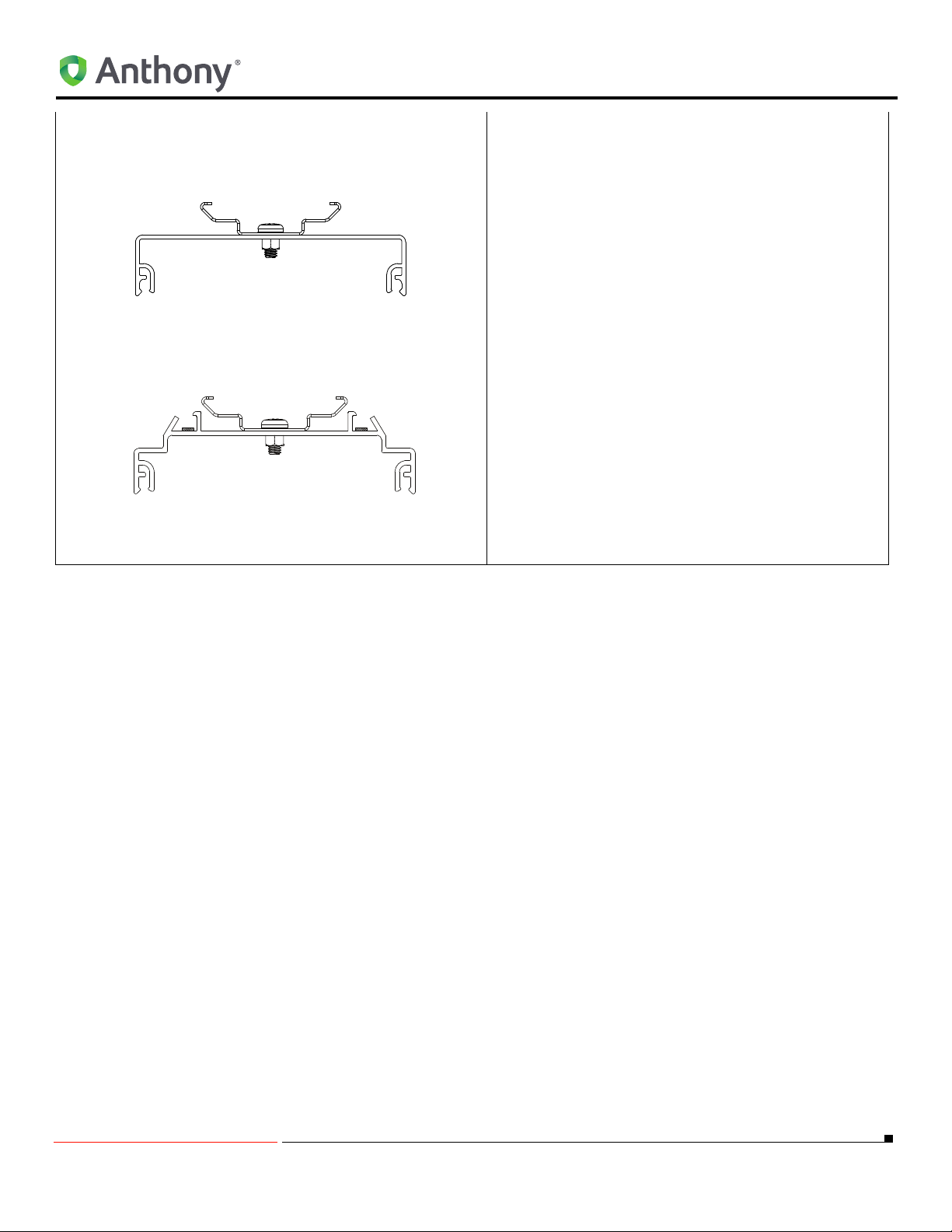
OptiMax2 RETROFIT INSTRUCTIONS FOR ANTHONY MODEL 401D AND 1KDR
9. Use a power drill and (#29) 0.136” dia. drill bit,
drill (6) holes at the intersection of the vertical
center line and the horizontal lines.
10. Insert two #8-32 X 1” screws thru each clip and
Mullion cover and secure with two #8-32 captive
nuts. A total of (6) screws, (3) nuts, and (3)
mounting clips should be installed.
11. Drill a 3/8” hole about 1/2” from the top of the
installed LED mounting clip.
NOTE: 3/8” hole will be used for bring the
leads from the wire plug assembly to the LED
fixture.
12. Go to Center Mullion LED Fixture Mounting
Instructions on page 16.
5/18/2010 22 99-18258-I001_A
Page 27
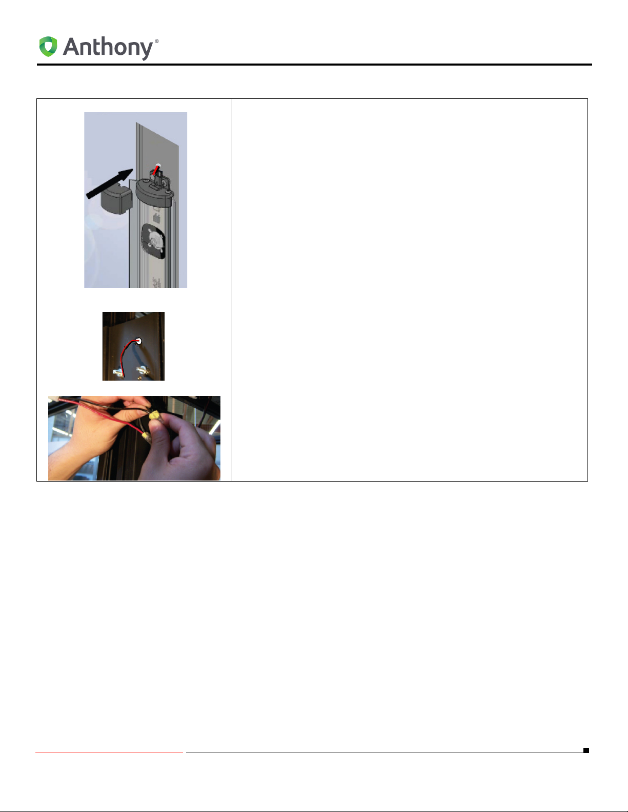
Connecting LED Light Fixture to Wire Plug Assembly
1. Bring the wires from the LED fixture thru the 3/8” DIA. hole.
2. Connect wires from the LED light fixture to the black and red wires
from the 2-conductor harness (Refer to "RETROFIT LED COMPO-
NENTS" on page 3) using Wago Wall-NUT connector part number
773-162 or other approved connectors.
3. Snap the end cap onto LED light fixture making sure the wire cover is
locked into the end cap.
4. Remove the protective film from the lens.
5. Seal off the cutouts in the Mullions using insulating material.
a. For wiring diagram Refer to "Fixture Orientation" on page 32.
b. Continue to “MOUNTING THE LED POWER SUPPLIES" on page
30.
OptiMax2 RETROFIT INSTRUCTIONS FOR ANTHONY MODEL 401D AND 1KDR
5/18/2010 23 99-18258-I001_A
Page 28
Ardco FRAMES
ACORN NUT
MULLION
MOUNTING CLIP
HEX NUT AND
LOCKWASHER
FOAM TAPE
Typical Orientations
Refer to "STANDARD CONFIGURATION" on page 36.
Parts Removal
1. Turn the power switch to the frame off.
2. Disconnect the frame from the main power.
3. Remove all of the old lamps and light fixtures from the frame.
NOTE: All hardware should be taken off, this includes lamp
guards, clips and fasteners.
4. Remove all acorn nuts along the Mullion.
5. Close any holes along the Mullion with a 1/32” thick foam sealant.
Refer to "ADDITIONAL PARTS REQUIRED FOR Ardco FRAME" on
page 5 and Refer to Figure 1 and Figure 2 .
Figure 1
6. Install three LED mounting clips onto the lamp side of the Mullion using
#10-32 hex nuts and lock washers. Refer to "ADDITIONAL PARTS
REQUIRED FOR Ardco FRAME" on page 5.
7. Clip should be installed near the top, the bottom and at the midpoint of
the Mullion.
Ardco FRAMES
Figure 2
NOTE: Do not use the acorn nuts previously removed to fasten
the clips. Refer to
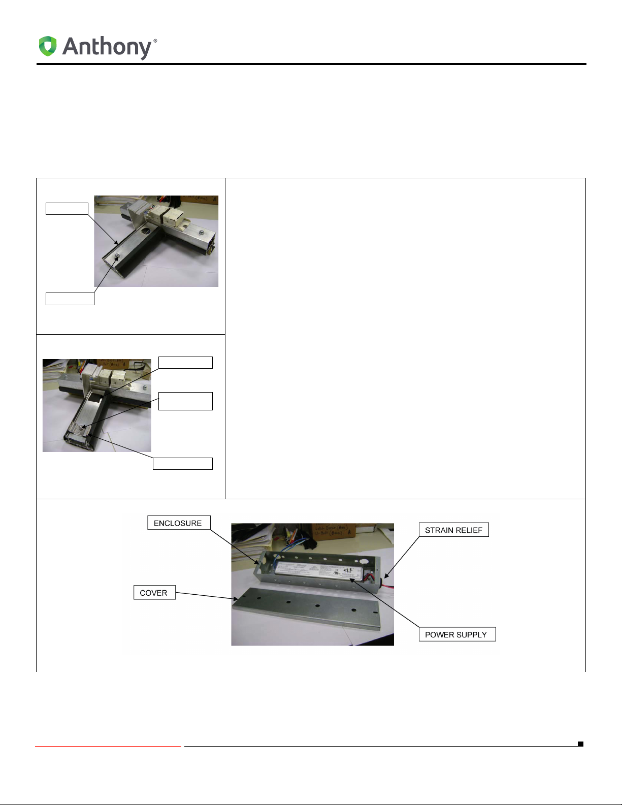
8. Install the LED power supply(s) into a UL approved enclosure. Refer
to "ADDITIONAL PARTS REQUIRED FOR Ardco FRAME" on page 5.
Figure 3
Figure 2 .
5/18/2010 24 99-18258-I001_A
Page 29
Ardco FRAMES
9. Route the LED connector as shown in Figure 3 . The LED cable
assembly must pass through an appropriate UL approved strain relief
or an approved cover cap not shown in Figure 3 .
NOTE: Additional hardware to install the power supply and
remote enclosures can be supplied by A.I. Refer to
Orientation" on page 32
10. The Red and Black main input power must pass through an appropriate UL approved strain relief secured to the enclosure to prevent wire
damage.Refer to Figure 3 .
11. LED power transformer:
a. Cut off the of the 3-position plug on the LED power supply and strip
the Blue (Hot), Green/yellow (GND) and White/Blue wires.
b. Connect the Red main input power wire to Blue LED power supply
wire using a Wago Wall-NUT connectors or approved connector.
c. Connect the Black main input power wire to Black LED power
supply wire using a Wago Wall-NUT connector or approved
connector.
12. Plug all unused holes on the enclosure with an approved cover cap.
13. Mount the remote enclosure(s) to the top header above the frame.
.
"Fixture
NOTE: Before installing the OptiMax2 lamp assembly into the
clips verify the following (Refer to
a. The wire leads exiting the lamps are oriented correctly for connec-
tion to the LED power supplies.
b. The right and left Mullions will use a lamp fixture marked with “RT”
and “LT” respectively.
c. The center Mullions will use the fixture labeled with “CTR”.
14. Install the OptiMax2 LED lamp assembly to the clips on the Mullion by:
a. Align the LED light with the mounting clips so that the LEDs are
facing the displace case interior.
b. Snap the LED light into the mounting clips:
c. By placing one end of the LED light into the groove.
d. Gently rotate until the opposite edge firmly locks into the mounting
clip.
"Fixture Orientation" on page 32):
NOTE: Ensure that the mounting clips lock into the outer edge
of the LED light aluminum extrusion.
e. Adjust the lamp position until it is centered on the Mullion.
15. Continue to “Locking LED Fixture to Center Mullion Fixture" on page 8.
5/18/2010 25 99-18258-I001_A
Page 30
HUSSMANN FRAME
Removing Existing Lighting System
Refer to "Removing Existing Lighting System:" on page 6.
Locate, Drill and Mount the LED Fixture Mounting Clips for Hussmann Frame
1. Place a mounting clip at the top of the Mullion against the
outer edge away from the wall and mark one hole at (
1. Place the same mounting clip at the bottom of the Mullion
against the other edge away from the wall and mark one
hole at (
2. Mark a vertical line from (
3. Divide the vertical line (
center line
4. Mark a horizontal line (
line (
5. Mark two horizontal lines, one from the center (
lows:
a. For 72” fixture-- 30.125” (
B).
D) to (B).
D) and (B) in half and mark as a
(A).
G) 7/16” (0.438”) below the center
A).
HUSSMANN FRAME
A) as fol-
A) to (C) and (A) to (E).
D).
b. For 60” fixture-- 25.475” (
c. For 48” fixture-- 20.825”
6. Mark one horizontal mark (
(
C).
7. Mark one horizontal line (
A) to (C) and (A) to (E).
(A) to (C) and (A) to (E).
F) 7/16” (0.438”) below the line
H) 7/16” (0.438”) above the line
(E).
8. Center the center punch directly over at the intersection of
the horizontal lines (6 total) and the vertical line (top, center and bottom) and establish a dimple.
9. Use a power drill and (#29) 0.136” dia. drill bit, drill (6)
holes at the intersection of the vertical center line and the
horizontal lines.
10. Repeat step1. thru step 9. for the opposite side end Mul-
lion.
11. Using a Phillips screw driver, tread the two #8 tapping
screws (supplied) to hold each mounting clip. A total of (6)
screws and (3) mounting clips should be installed per
Mullion.
12. Refer to "Fixture Orientation" on page 32.
13. Continue to “Orientation Of End Fixtures" on page 11.
5/18/2010 26 99-18258-I001_A
Page 31
End Mullion Fixture LED Mounting Instructions
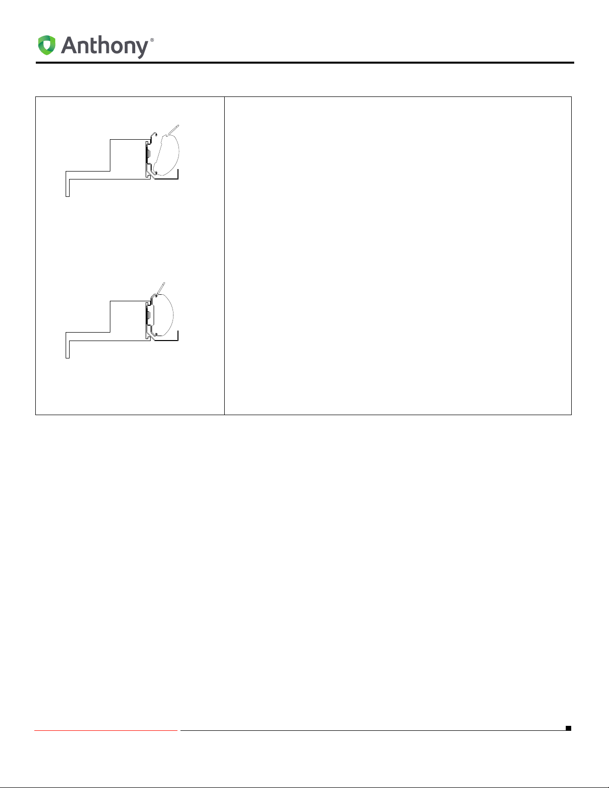
1. Align the LED light with the mounting clips so that the LEDs are facing the displace case interior. Snap the LED light into the mounting
clips:
a. By placing one end of the LED light into the groove.
b. Gently rotate until the opposite edge firmly locks into the mounting
NOTE: Ensure that the mounting clips lock into the outer edge
of the LED light aluminum extrusion.
c. Adjust the LED lamp assembly until it is centered on the Mullion.
2. To lock LED fixture to Mullion:
a. Right end Mullion, refer to “Connecting Wires at the Bottom of the
b. Left end Mullion, refer to “Connecting Wires at the Top of the
3. To lock LED Fixture:
a. Locking LED fixture to right end Mullion (wires connected at bottom
HUSSMANN FRAME
clip.
Frame on page 28.
Frame on page 28.
of frame) Continue to “Locking LED Fixture to Right End Mullion
Fixture (Wires Connected at Bottom of Frame)" on page 12.
b. Locking LED fixture to left end Mullion fixture (wires connected at
top of frame) Continue to “Locking LED Fixture to Left End Mullion
Fixture (Wires Connected at Top of Frame)" on page 13.
5/18/2010 27 99-18258-I001_A
Page 32
CONNECTING THE WIRE PLUG ASSEMBLY TO THE
LED FIXTURE WIRES
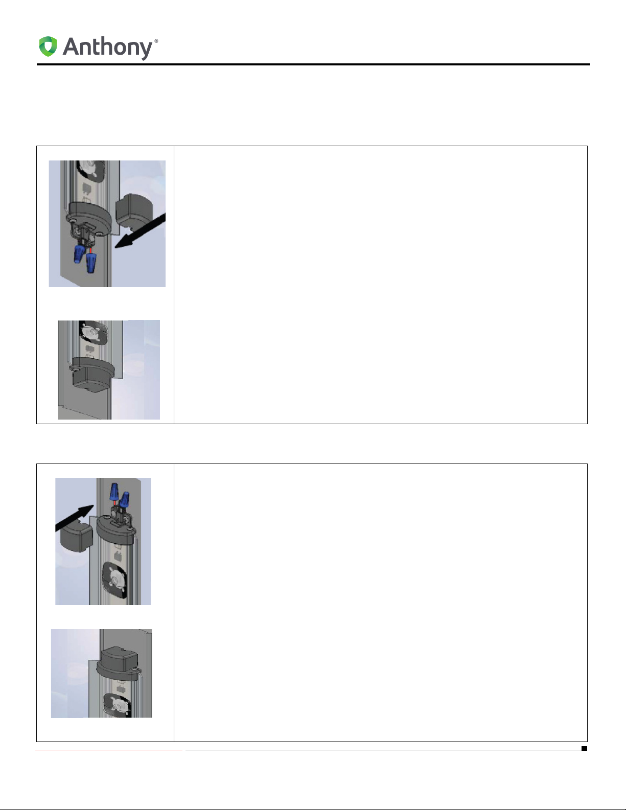
Connecting Wires at the Bottom of the Frame
1. Connect wires from the fixture to the black and red wires from the 2-conductor
harness using Wago Wall-NUT connector part number 773-162 or other approved
connectors.
NOTE: End fixtures need to be connected together. Refer to "Center Mullion
LED Fixture Mounting Instructions" on page 8
2. Tuck the wire connectors underneath the wire cover before snapping it to the end
cap.
3. Make sure the wire cover is locked into the end cap.
4. Remove the protective film from the lens.
5. Seal off the cutouts in the Mullions using insulating material.
6. Continue to “MOUNTING THE LED POWER SUPPLIES" on page 30.
CONNECTING THE WIRE PLUG ASSEMBLY TO THE LED FIXTURE WIRES
.
Connecting Wires at the Top of the Frame
1. Connect wires from the fixture to the black and red wires from the 2-conductor
harness ( Refer to "RETROFIT LED COMPONENTS" on page 3) using Wago
Wall-NUT connector part number 773-162 or other approved connectors.
NOTE: End fixtures need to be connected together. Refer to "Center Mullion
LED Fixture Mounting Instructions" on page 8
2. Tuck the wire connectors underneath the wire cover before snapping it to the end
cap.
3. Make sure the wire cover is locked into the end cap.
4. Remove the protective film from the lens.
5. Seal off the cutouts in the Mullions using insulating material.
6. Continue to “MOUNTING THE LED POWER SUPPLIES" on page 30.
.
5/18/2010 28 99-18258-I001_A
Page 33

CONNECTING THE WIRE PLUG ASSEMBLY TO THE LED FIXTURE WIRES
5/18/2010 29 99-18258-I001_A
Page 34
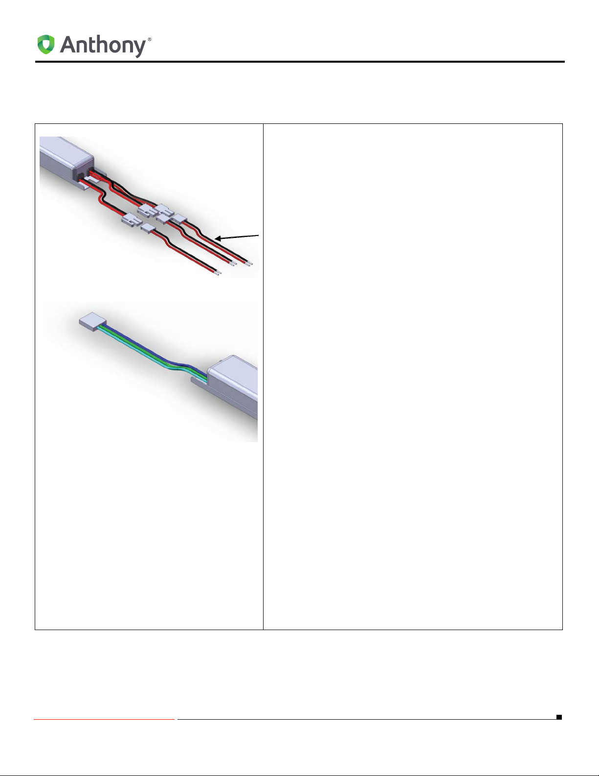
MOUNTING THE LED POWER SUPPLIES
Low Power (3-in-1 Driver)
MOUNTING THE LED POWER SUPPLIES
1. Install the LED power supply in the same location where the
ballast was fitted or in the general location for ease of wire
connection.
2. Mount the LED power supply using two #8 tapping screws
saved when the ballast was removed.
NOTE: Installer may have to drill two holes in raceway
to accommodate LED power supply.
NOTE: The LED power supply case is grounded.
Attach the LED power supply to a ground point in the
refrigerated case either directly with a screw or by
using the green wire to attach to a remote point.
3. Connect LED Light fixture wire connectors to LED power
supply using plug assembly provided. Refer to "RETROFIT
LED COMPONENTS" on page 3 .
4. Connect the 3-position plug on the primary side of the LED
power supply as follows:
a. If a 3-position plug is present on the load wire harness go
to step 5.
b. If no 3-position plug is present on the load wire harness
go step 6.
5. Connect the primary LED power supply input 3-position
plug (blue, green and white/blue wires) to the harness 120240 VAC electrical 3-position plug (blue/white and white/
blue wires). Go to step 7.
6. If no 3-position plug is present on the load wire harness:
a. Cut off the 3-position plug on LED power supply.
b. Connect the blue (+) on LED power supply to the original
load blue/white wire on the frame using a Wago WallNUT connector part number 773-162 or approved
connector.
a. Connect the white/blue (-) on the LED power supply to
the original load white/blue wire from the frame using a
Wago Wall-NUT connector part number
773-162 or approved connector.
7. Reinstall raceway cover(s).
8. Turn power on and verify LED fixture(s) are working.
5/18/2010 30 99-18258-I001_A
Page 35
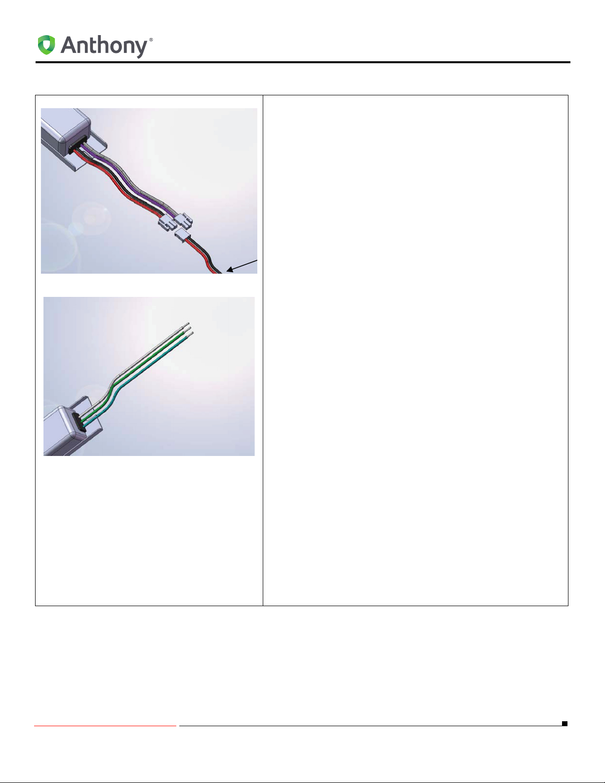
Low and High Power
MOUNTING THE LED POWER SUPPLIES
1. Install the LED power supply in the same location where the
ballast was fitted or in the general location for ease of wire
connection.
2. Mount the LED power supply using two #8 tapping screws
saved when the ballast was removed.
NOTE: Installer may have to drill two holes in raceway
to accommodate LED power supply.
NOTE: The LED power supply case is grounded. Attach
the LED power supply to a ground point in the
refrigerated case either directly with a screw or by
using the green wire to attach to a remote point.
3. Connect LED Light fixture wire connectors to LED power
supply using plug assembly provided. Refer to "RETROFIT
LED COMPONENTS" on page 3.
4. Connect the 3-position plug on the primary side of the LED
power supply as follows:
a. If a 3-position plug is present on the load wire harness go
to step 5.
b. If no 3-position plug is present on the load wire harness
go step 6.
5. Connect the primary LED power supply input 3-position plug
(blue, green and white/blue wires) to the harness 120-240
VAC electrical 3-position plug (blue/white and white/blue
wires). Go to step 7.
6. If no 3-position plug is present on the load wire harness:
a. Cut off the 3-position plug on LED power supply.
b. Connect the blue (+) on LED power supply to the original
load blue/white wire on the frame using a Wago WallNUT connector part number 773-162 or approved
connector.
a. Connect the white/blue (-) on the LED power supply to the
original load white/blue wire from the frame using a Wago
Wall-NUT connector part number 773-162 or approved
connector.
7. Reinstall raceway cover(s).
8. Turn power on and verify LED fixture(s) are working.
5/18/2010 31 99-18258-I001_A
Page 36
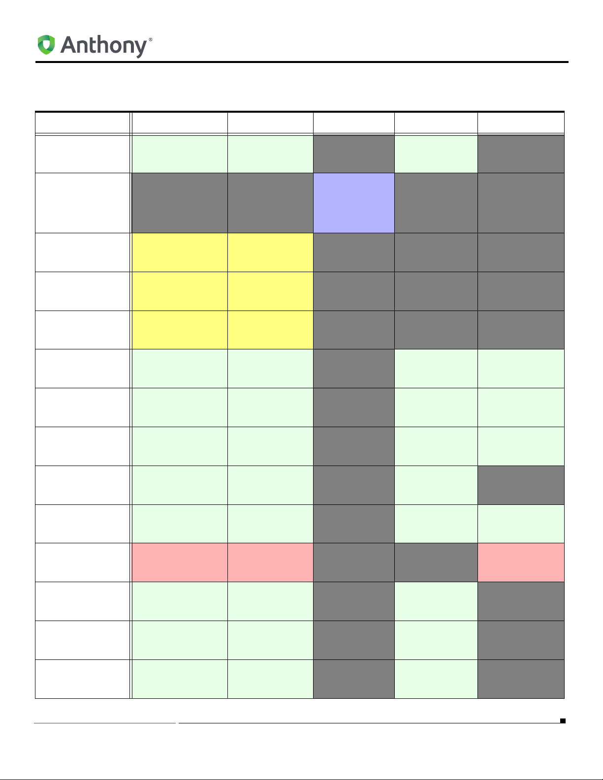
Table 1: Fixture Orientation
MOUNTING THE LED POWER SUPPLIES
Orientation Center Mullion End Mullion 401D, 1KDR,
ELS
“(Standard
Configuration (5-Door)”
on page 37
“3-Door (Upper
Raceway)”
on
page 42
“Center Mullion LED
Fixture Mounting
Instructions”
on
page 8
“END MULLION
FIXTURE”
on
page 10
“OptiMax2
RETROFIT
INSTRUCTIONS
FOR ANTHONY
MODEL 401D AND
1KDR”
page 14
“FULL POWER End &
MULL Option (2-Door)”
on page 39
“FULL POWER End &
MULL Option (3-Door)”
on page 39
“FULL POWER End
Option (1-Door)”
on
page 39
“HALF POWER End &
MULL Options (3-in-1
Drive, 2-Door)” on
page 40
“HALF POWER End &
MULL Options (3-in-1
Driver, 4-Door)” on
page 41
“HALF POWER End &
MULL Options (3-in-1
Driver, 5-Door)” on
page 41
“HALF POWER End &
MULL Options (6-Door)”
on page 41
“HALF POWER End
Options (3-in-1, Driver 1Door)” on page 40
“ORIENTATION OF
CENTER FIXTURES”
on
page 34
“STANDARD
CONFIGURATION (1-
on page 36
Door)”
“STANDARD
CONFIGURATION (2Door)”
on page 36
“STANDARD
CONFIGURATION (3Door)” on page 37
“Center Mullion LED
Fixture Mounting
Instructions”
on
page 8
“Center Mullion LED
Fixture Mounting
Instructions”
on
page 8
“Center Mullion LED
Fixture Mounting
Instructions”
on
page 8
“Center Mullion LED
Fixture Mounting
Instructions”
on
page 8
“Center Mullion LED
Fixture Mounting
Instructions”
on
page 8
“Center Mullion LED
Fixture Mounting
Instructions”
on
page 8
“Center Mullion LED
Fixture Mounting
Instructions”
on
page 8
“Center Mullion LED
Fixture Mounting
Instructions”
on
page 8
“Center Mullion LED
Fixture Mounting
Instructions”
on
page 8
“Center Mullion LED
Fixture Mounting
Instructions”
on
page 8
“Center Mullion LED
Fixture Mounting
Instructions”
on
page 8
“Center Mullion LED
Fixture Mounting
Instructions”
on
page 8
“END MULLION
FIXTURE”
on
page 10
“END MULLION
FIXTURE”
on
page 10
“END MULLION
FIXTURE”
on
page 10
“END MULLION
FIXTURE”
on
page 10
“END MULLION
FIXTURE”
on
page 10
“END MULLION
FIXTURE”
on
page 10
“END MULLION
FIXTURE”
on
page 10
“END MULLION
FIXTURE”
on
page 10
“Center Mullion LED
Fixture Mounting
Instructions”
on
page 8
“END MULLION
FIXTURE”
on
page 10
“END MULLION
FIXTURE”
on
page 10
“END MULLION
FIXTURE”
on
page 10
on
ARDCO Frame HUSSMANN
Frame
“Ardco FRAMES”
on page 24
“Ardco FRAMES”
on page 24
“HUSSMANN
FRAME”
on
page 26
“Ardco FRAMES”
on page 24
“HUSSMANN
FRAME”
on
page 26
“Ardco FRAMES”
on page 24
“HUSSMANN
FRAME”
on
page 26
“Ardco FRAMES”
on page 24
“Ardco FRAMES”
on page 24
“HUSSMANN
FRAME”
on
page 26
“HUSSMANN
FRAME”
on
page 26
“Ardco FRAMES”
on page 24
“Ardco FRAMES”
on page 24
“Ardco FRAMES”
on page 24
5/18/2010 32 99-18258-I001_A
Page 37
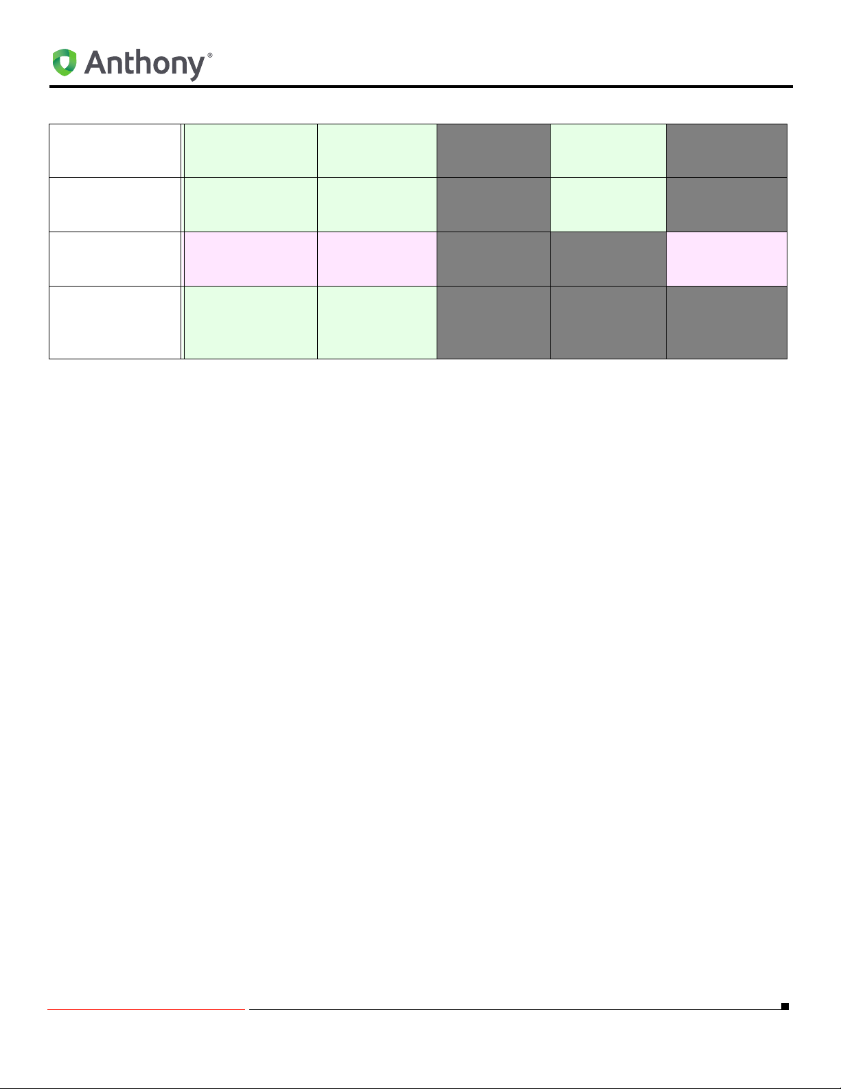
Table 1: Fixture Orientation (Continued)
MOUNTING THE LED POWER SUPPLIES
“Standard Configuration
(4-Door)”
“STANDARD
CONFIGURATION (6Door)”
“TYPICAL
INSTALLATION (4-Dr
Frame Shown, 3-in-1
Driver)”
“TYPICAL
INSTALLATION (HALF
POWER END FIXTURES
WITH SINGLE FIXTURE
DRIVERS)” on
on page 37
on page 38
on page 40
page 36
“Center Mullion LED
Fixture Mounting
Instructions”
on
page 8
“Center Mullion LED
Fixture Mounting
Instructions”
on
page 8
“Center Mullion LED
Fixture Mounting
Instructions”
on
page 8
“Center Mullion LED
Fixture Mounting
Instructions”
on
page 8
“END MULLION
FIXTURE”
on
page 10
“END MULLION
FIXTURE”
on
page 10
“END MULLION
FIXTURE”
on
page 10
“END MULLION
FIXTURE”
on
page 10
“Ardco FRAMES”
on page 24
“Ardco FRAMES”
on page 24
“HUSSMANN
FRAME”
on
page 26
5/18/2010 33 99-18258-I001_A
Page 38
Typical input
wires
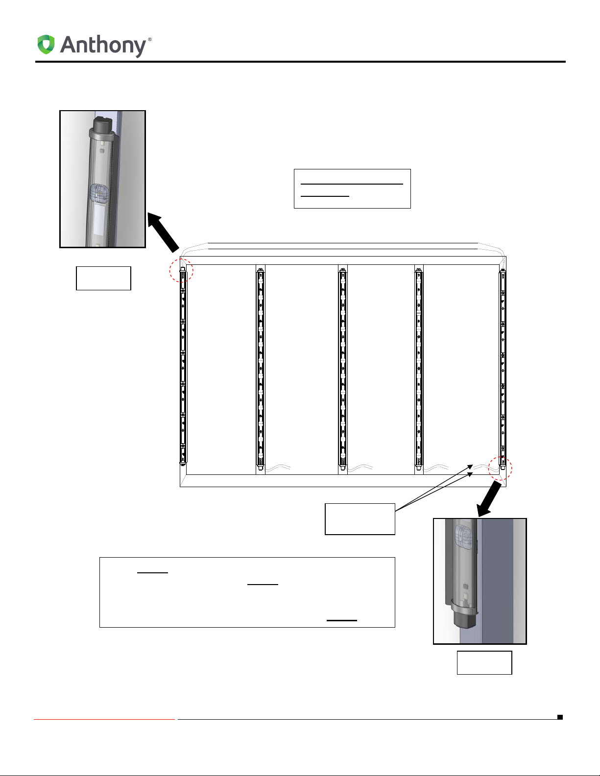
x Side 2 end fixture will remain the same orientation as
the center light fixtures. Side 1
end fixture must be
flipped over for the correct orientation as shown.
Therefore, the installer must connect the wires at the
top of the frame instead of the bottom as Side 2
.
Viewed from the inside
of the case.
SIDE 1
SIDE 2
ORIENTATION OF CENTER FIXTURES
ORIENTATION OF CENTER FIXTURES
5/18/2010 34 99-18258-I001_A
Page 39

ORIENTATION OF CENTER FIXTURES
5/18/2010 35 99-18258-I001_A
Page 40
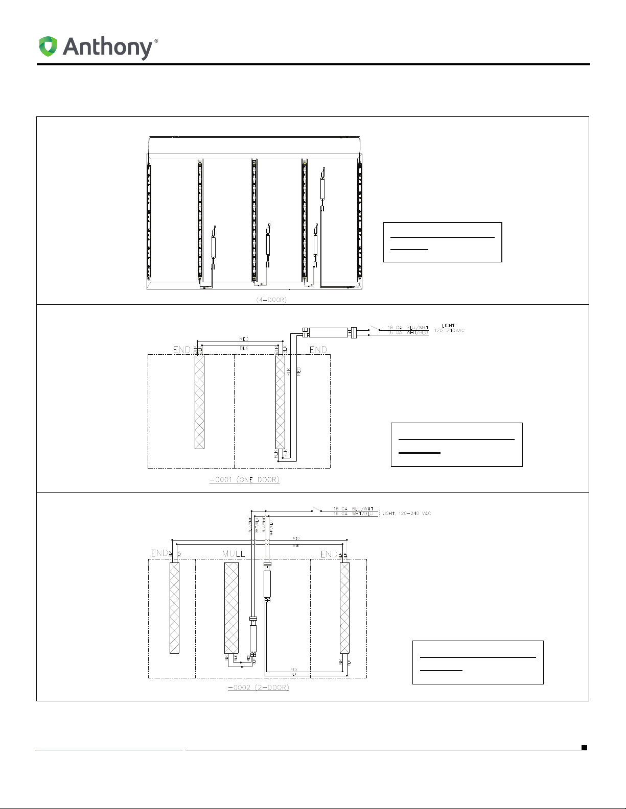
View from the inside of
the case.
View from the inside of
the case.
View from the inside of
the case.
STANDARD CONFIGURATION
STANDARD CONFIGURATION
TYPICAL INSTALLATION (HALF POWER END FIXTURES WITH SINGLE FIXTURE DRIVERS)
STANDARD CONFIGURATION (1-Door)
STANDARD CONFIGURATION (2-Door)
5/18/2010 36 99-18258-I001_A
Page 41
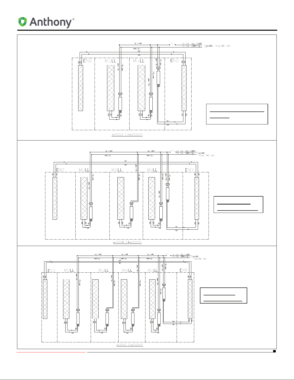
STANDARD CONFIGURATION (3-Door)
View from the inside of
the case.
View from the
inside of the case.
View from the
inside of the case.
Standard Configuration (4-Door)
STANDARD CONFIGURATION
(Standard Configuration (5-Door)
5/18/2010 37 99-18258-I001_A
Page 42
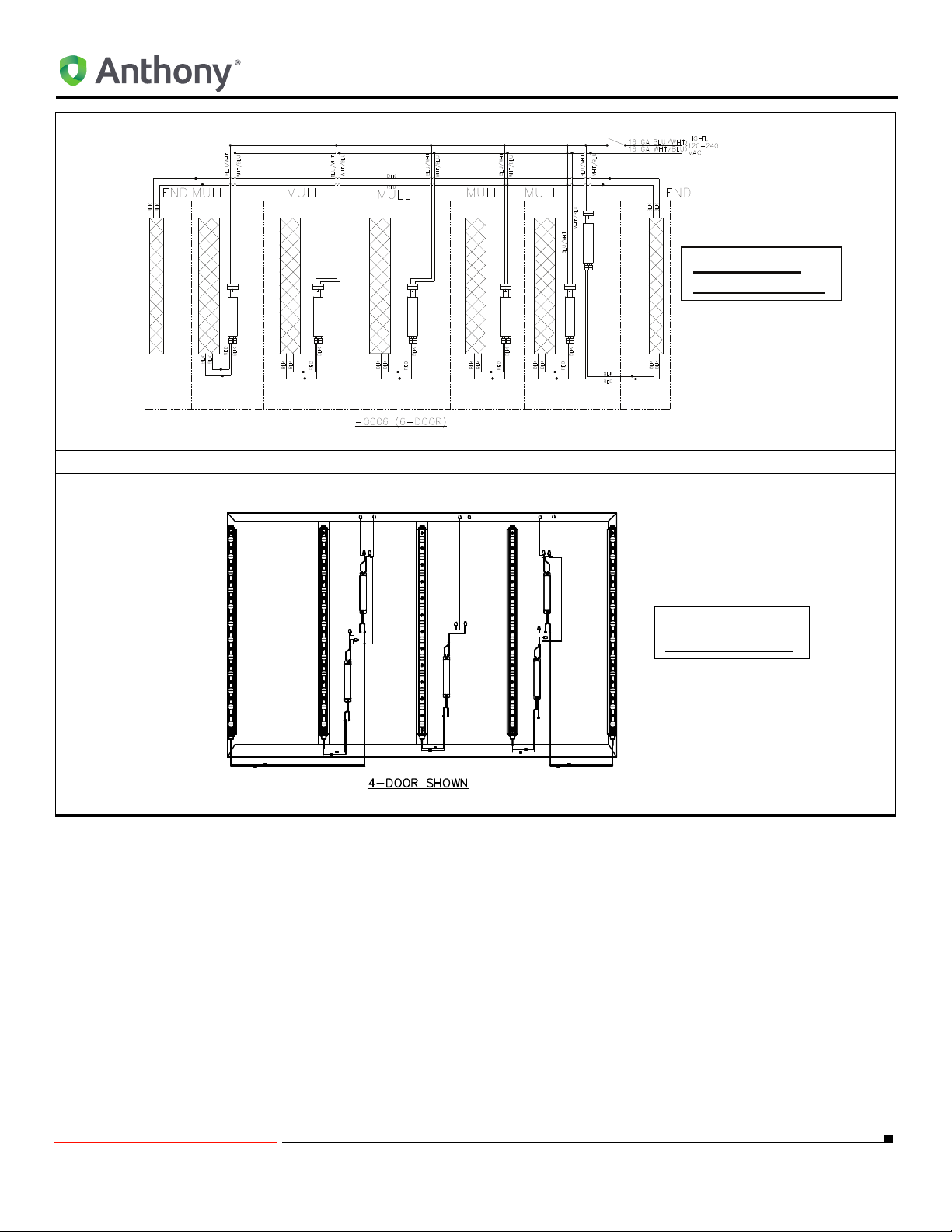
STANDARD CONFIGURATION (6-Door)
View from the
inside of the case.
View from the
inside of the case.
OPTIONAL CONFIGURATION (FULL POWER ENDS)
FULL POWER ENDS OPTION
STANDARD CONFIGURATION
5/18/2010 38 99-18258-I001_A
Page 43
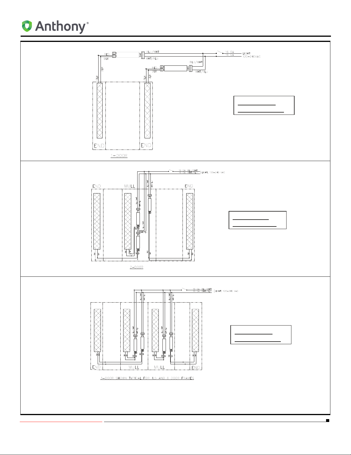
FULL POWER End Option (1-Door)
View from the
inside of the case.
View from the
inside of the case.
View from the
inside of the case.
FULL POWER End & MULL Option (2-Door)
STANDARD CONFIGURATION
FULL POWER End & MULL Option (3-Door)
5/18/2010 39 99-18258-I001_A
Page 44
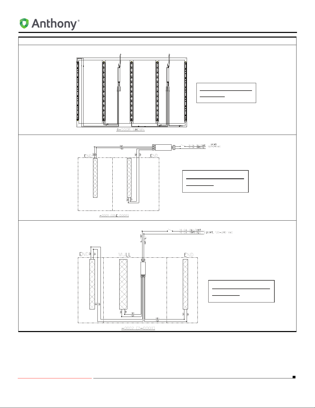
CONFIGURATION (MULTI-FIXTURE DRIVER)
Viewed from the inside
of the case.
Viewed from the inside
of the case.
Viewed from the inside
of the case.
TYPICAL INSTALLATION (4-Dr Frame Shown, 3-in-1 Driver)
HALF POWER End Options (3-in-1, Driver 1-Door)
STANDARD CONFIGURATION
HALF POWER End & MULL Options (3-in-1 Drive, 2-Door)
5/18/2010 40 99-18258-I001_A
Page 45
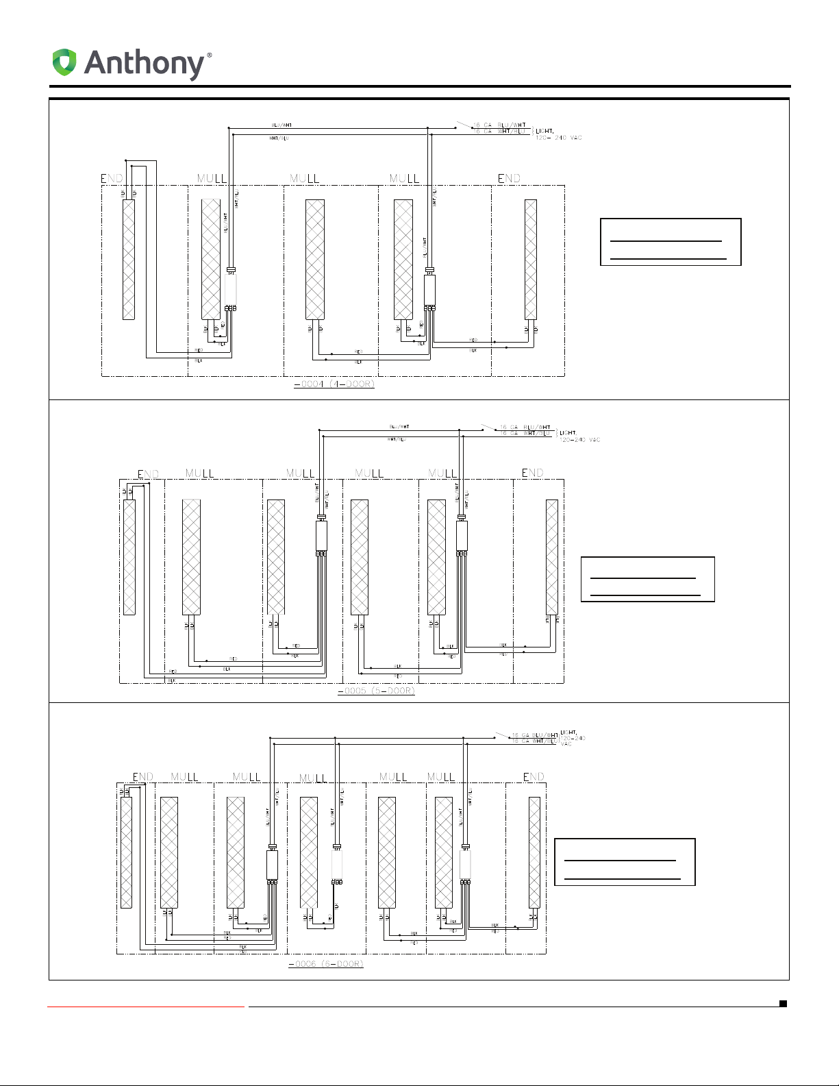
HALF POWER End & MULL Options (3-in-1 Driver, 4-Door)
Viewed from the
inside of the case.
Viewed from the
inside of the case.
Viewed from the
inside of the case.
HALF POWER End & MULL Options (3-in-1 Driver, 5-Door)
STANDARD CONFIGURATION
HALF POWER End & MULL Options (6-Door)
5/18/2010 41 99-18258-I001_A
Page 46
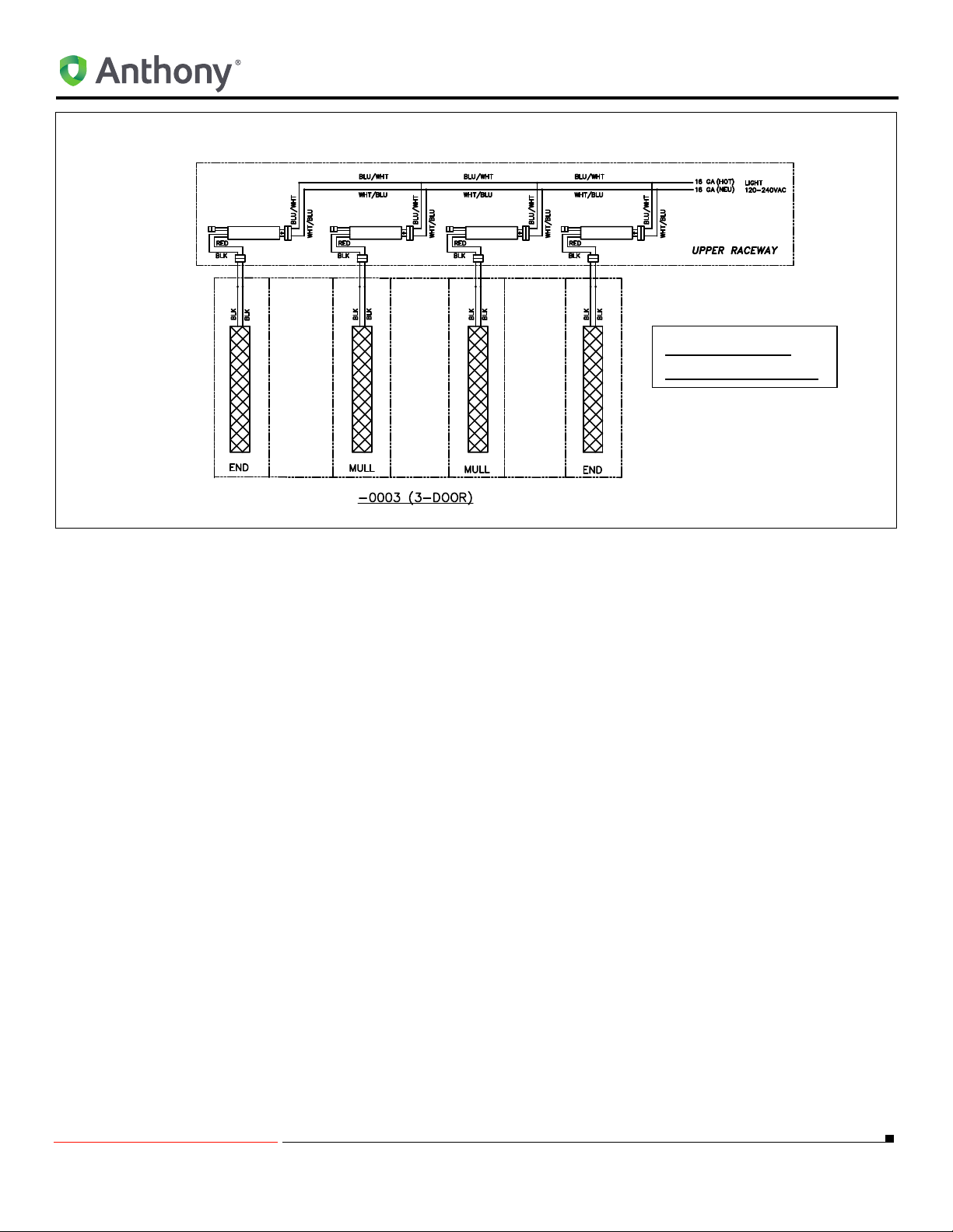
3-Door (Upper Raceway)
View from the
inside of the case.
STANDARD CONFIGURATION
5/18/2010 42 99-18258-I001_A
Page 47

STANDARD CONFIGURATION
5/18/2010 43 99-18258-I001_A
Page 48
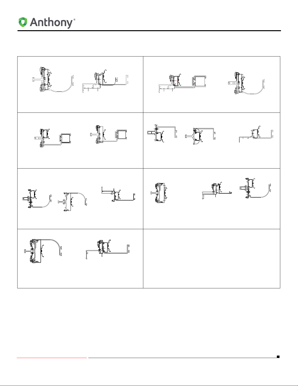
MULLION CONFIGURATIONS
MULLION CONFIGURATIONS
1001 w/ELS System
1001 T10-12 1001 T10-T123
401D/401B 401 D/401B 401D/401B
1001 T10-T12 1001 w/E:S System
401 (old) 401 (old) 401 (old)
1KDR/1KDB 1KDR/1KDB 1KDB/1KDR
1KDR/1KDB Standard T12
5/18/2010 44 99-18258-I001_A
Page 49

MULLION CONFIGURATIONS
5/18/2010 45 99-18258-I001_A
Page 50

LED CLEANING INSTRUCTIONS
LED CLEANING INSTRUCTIONS
• The LED light may be dusted as needed with a dry, clean, soft cloth.
• The outer lens should be cleaned periodically with a mild dish detergent.
• Do not use chemical cleaners to clean the system.
• Keep the outside clean. Wipe with a clean cloth lightly damped with mild dish washer detergent. Dry with a
clean, soft cloth
• Do not wipe the lens with a soiled dish cloth or wet towel. These may leave a residue that can damage the finish.
• Do not use scouring pads, powered cleaners, bleach or cleaners containing bleach because these products can
scratch and damage the finish.
5/18/2010 46 99-18258-I001_A
Page 51

LED CLEANING INSTRUCTIONS
5/18/2010 47 99-18258-I001_A
Page 52

12391 Montero Street, Sylmar, CA 91342
800.772.0900 www.anthonyintl.com
99-18258-I001_A
 Loading...