

Arctic Cat ZR 6000R SX, ZR 6000R XC Service Manual


This vehicle can be hazardous to operate.
A snowmobile is a very high performance vehicle. Because it does accelerate rapidly and is capable of very high
speeds, it should not be operated by a novice or an inexperienced operator. Never accelerate rapidly or drive at high
speed beyond the limits of visibility or without being totally familiar with the terrain and what lies in front of you.
Obey speed limits and never operate at speeds that do not allow adequate maneuvering and stopping distances.
Read and study the entire Operator’s Manual and Snowmobile Safety Handbook.
Failure to follow this warning could result in personal injury to yourself or others. For your safety, understand and
follow all the warnings contained in this Operator’s Manual and on the labels on this vehicle.
Keep this Operator’s Manual with this vehicle at all times. If you lose your manual, contact your authorized dealer
for a free replacement. The labels should be considered permanent parts of the vehicle. If a label comes off or
becomes hard to read, contact your authorized dealer for a free replacement. Contact Arctic Cat Service Department, P.O. Box 810, Thief River Falls, MN 56701, for proper registration information.
FAILURE TO FOLLOW THE WARNINGS CONTAINED IN THIS MANUAL CAN RESULT IN SERIOUS
INJURY OR DEATH.
The Operator’s Manual, Snowmobile Safety Handbook, and Snowmobile Decals display important information:
The Safety Alert Symbol means ATTENTION! BE ALERT!
!
YOUR SAFETY IS INVOLVED.
! WARNING
CAUTION
NOTE:
WARNING identifies personal safety-related information. Follow the
directive because it deals with the possibility of serious personal
injury or even death.
CAUTION, without the safety alert symbol, identifies unsafe
practices which may result in snowmobile-related damage. Follow the directive because it deals with the possibility of damaging part or parts of the snowmobile.
A NOTE identifies supplementary information worthy of particular attention.
Personal Injury
• To avoid injury to yourself and others, NEVER operate the snowmobile without first reading and understanding this manual and the Snowmobile Safety Handbook; then follow the instructions and heed the warnings
given.
• USE COMMON SENSE.
• DON’T DRINK and DRIVE.
• STAY IN CONTROL at ALL TIMES.
• TELL YOUR FRIENDS. If you see a friend operating a snowmobile recklessly, at excessive speeds, while
intoxicated, or in other unsafe ways, don’t wait until it is too late to warn of the consequences of snowmobile
misuse. Such conduct endangers everyone. TAKE AN ACTIVE ROLE IN THE SAFETY OF YOURSELF AND
OTHERS.
California Proposition 65
! WARNING
The Engine Exhaust from this product contains chemicals known to the State of California to
cause cancer, birth defects or other reproductive harm.

Limited Warranty
Arctic Cat Inc. (hereinafter referred to as Arctic Cat) extends a limited warranty as described below on each new Arctic Cat Snowmobile it assembles and on each
genuine Arctic Cat Snowmobile part and accessory assembled and sold by an authorized Arctic Cat Snowmobile dealer. The limited warranty on an Arctic Cat
Snowmobile is extended to the original retail purchaser for the time periods described below; however, the balance of the remaining warranty may be transferred to
another party unless the purchase is for commercial use (see below). Warranty coverage is only available in the country in which the original retail purchase occurs
to the original retail purchaser resident in that country or to a transferee resident in that country of the balance of the remaining warranty.
Arctic Cat warrants only the products it assembles and/or sells and does not warrant that other products will function properly when used with an Arctic Cat
Snowmobile or will not damage the Arctic Cat Snowmobile. Arctic Cat does not assume any liability for incidental or consequential damages.
Arctic Cat will repair or replace, a t its op tion, free of char ge ( inclu ding a ny r elated labo r ch arge s), a ny p arts that a re fou nd to be warrantable in material or workmanship.
This repair work MUST be done by an authorized Arctic Cat Snowmobile dealer. No transportation charges, rental charges, or inconvenience costs will be paid by Arctic
Cat. The warranty is validated upon ex amin ation of said parts by Arctic Cat or an authorized A rctic C at Snowmobile dealer. Arctic Cat reserves the right to inspect such
parts at its factory for final determination if warranty should apply.
The warranty periods are as follows:
1. For snowmobiles used for recreational purposes:
—If purchased between May 1 and November 30, warranty expires ONE (1) YEAR from December 1 of the current year.
—If purchased between December 1 and April 30, ONE (1) YEAR from the date of sale.
2. For snowmobiles used for commercial purposes (including rental operations), ONE (1) YEAR from the date of invoice and/or 5000 MILES whi chever comes first
(non-transferable).
3. THIRTY (30) DAYS from date of sale of snowmobile on Arctic Cat supplied batteries.
Exclusions to this warranty include normal wear, abuse (i.e. a track run on marginal snow conditions without proper lubrication or additional idl er wheels), and the
following parts:
Fuel Filter Light Bulbs Windshield Drive Belt Torn or Punctured Upholstery
Wear Bars Brake Pads Spark Plugs Drive Clutch/Driven Clutch Wear Parts
Wear Strips Shock Absorber(s) - Standard* Shock Absorber(s) - Rebuildable**
* Limited to one (1) year or 1000 miles of “normal” riding conditions - replace for defective or leaking shock, corroded or pitted shaft, peeling chrome.
** Limited to one (1) year or 1000 miles of “normal” riding conditions - rebuild for leaking shock (warranted) - replace for defective shock, corroded or pitted shaft, peeling
chrome.
The following will VOID Arctic Cat’s warranty:
1. Failure to perform the proper break-in procedure and all related maintenance, storage procedures (if stored for extended periods), and/or service as
recommended in the Operator’s Manual.
2. Repairs and/or adjustments by anyone other than an authorized Arctic Cat Snowmobile dealer.
3. Use of an improper fuel mixture ratio.
4. Use of improper gasoline, lubricating oils, or spark plugs.
5. An accident or subjecting the snowmobile to misuse, abuse, or negligent operation.
6. Any modification, addition, or removal of parts unless instruct ed to do so by Arctic Cat.
7. Use of the snowmobile in any way for racing purposes.
8. Removal of the engine for use in another vehicle.
9. Removal or mutilation of the Vehicle Identification Number or Engine Serial Number.
10. Use of parts not sold or approved by Arctic Cat.
11. Track and tunnel damage resulting from either ice stud or hooker plate installation.
12. Damage due to improper transportation.
Arctic Cat shall not be responsible for and this limited warranty excludes recovery of economic, punitive, consequential and incidental damages, lost profits, and loss
of use. Some states or provinces do not allow the exclusion or limitation of incidental or consequential damages, so the above limitation may not apply to you. Arctic
Cat’s aggregate liability may not exceed the price of the product. The law of the State of Minnesota shall apply to all claims or disputes, exclusive of its conflicts of
law provisions.
IMPLIED WARRANTY EXCLUSION AND DISCLAIMER
To the fullest extent permitted by law, Arctic Cat excludes and disclaims all implied warranties of merchantability and fitness for a particular purpose.
If you are not satisfied with warranty service or repairs, you should contact Arctic Cat at (U.S.) 218-681-9851 or (Canada) 204-982-1656.
If the snowmobile is purchased through the Team Arctic Race
Department Racing Program, there is no warranty.

Foreword
Congratulations! You have chosen a quality Arctic Cat Snowmobile designed and manufactured to give dependable service. Be sure, as the owner/operator of an Arctic Cat Snowmobile, to become thoroughly familiar with its
basic operation, maintenance, and off-season storage procedures. Read this manual and the accompanying Snowmobile Safety Handbook before operating the snowmobile to ensure safe and proper use of your new Arctic Cat
Snowmobile. Always operate the snowmobile within your level of skill and current terrain conditions.
This manual covers operator-related maintenance, operating instructions, and off-season storage instructions. If
major repair or service is ever required, contact an authorized Arctic Cat Snowmobile dealer for professional service.
At the time of publication, all information and illustrations were technically correct. Some illustrations used in this
manual are used for clarity purposes only and are not designed to depict actual conditions. Because Arctic Cat Inc.
constantly refines and improves its products, no retroactive obligation is incurred.
This Operator’s Manual should be considered a permanent part of the snowmobile and must remain with the snowmobile at the time of resale. If the snowmobile changes ownership more than once, contact Arctic Cat Inc., Service
Department, P.O. Box 810, Thief River Falls, MN 56701, for proper registration information.
Every Arctic Cat Snowmobile meets or exceeds the standards of the Snowmobile Safety and Certification Committee and displays the SSCC decal. Arctic Cat endorses and encourages the safe use of all snowmobiles. Always wear
a helmet and eye protection. Drive with caution, observe all state and local regulations, and respect the rights of
others. ISMA members like Arctic Cat do their part to improve trails, sponsor events, and generally support the
sport of snowmobiling. As a member of the National Snowmobile Foundation, Arctic Cat Inc. promotes snowmobiling through education, charity, and research programs.
© 2018 Arctic Cat Inc.
Printed in U.S.A. October 2018

PARTS AND ACCESSORIES
When in need of replacement parts, oil, or accessories for your Arctic Cat Snowmobile, be sure to only
use GENUINE ARCTIC CAT PARTS, OIL, AND
ACCESSORIES. Only genuine Arctic Cat parts, oil,
and accessories are engineered to meet the standards
and requirements of your Arctic Cat Snowmobile.
For a complete list of accessories, refer to the current
Arctic Cat Accessory Catalog.
To aid in service and maintenance procedures on this
snowmobile, an Illustrated Parts Manual is available
through your local Arctic Cat Snowmobile dealer.
Reference Information
The Arctic Cat Snowmobile has two important identification numbers. The Vehicle Identification Number
(VIN) is stamped on the side of the tunnel. The Engine
Serial Number (ESN) is stamped into the crankcase of
the engine.
These numbers are required by the dealer to properly
complete warranty claims. No warranty will be
allowed by Arctic Cat Inc. if the engine serial number
or VIN is removed or mutilated in any way.
Always provide the snowmobile name, VIN, and ESN
when contacting an authorized Arctic Cat Snowmobile
dealer for parts, service, accessories, or warranty. If
the complete engine must be replaced, ask the dealer to
notify Arctic Cat for correct registration information.
Write the appropriate information for your Arctic Cat
Snowmobile in the spaces below. Always use these
numbers when referring to your snowmobile.
Model: ____________________________________
Date of Purchase: ____________________________
VIN (Vehicle Identification Number): ____________
ESN (Engine Serial Number):___________________
Your Arctic Cat Dealer: ______________________
Address: ___________________________________
Phone: ____________________________________

Table of Contents
Specifications/Charts/Patterns/Diagrams ............. 3-23
Specifications.......................................................... 3
Torque Specifications ............................................. 4
Torque Conversions (ft-lb/N-m) .............................. 4
Tightening Torque (General Bolts) ......................... 5
Crankshaft Runout/Repair Specifications ............... 5
Arctic Power Valve (APV) System Specifications... 5
Electrical Specifications....................................... ... 5
Component Voltage/Resistance Chart — Water
Temperature........................................................ 6
R-XC Team Drive Clutch Optional Components .... 7
R-SX Arctic Cat Drive Clutch/Driven Clutch Optional
Components ........................................................ 7
R-SX Arctic Cat Drive Clutch Cam Arms (w/Set
Screw) ................................................................. 8
Chain Case Performance Calibrations ................... 9
Chains and Sprockets........................................... 11
Rear Spring Selection........................................... 11
Installed Spring Rate Chart................................... 11
Front Suspension Sway Bar ................................. 11
Rebuildable Shock Tools Required ...................... 12
Optional Front Arm Shock Springs — R-XC......... 12
Optional Dual Rate Spring Chart (DSR)............... 12
Rebuildable Shock Accessory Part Numbers....... 15
Fraction/Decimal Conversion Chart..................... . 16
Drill Bit Sizes (Number) Chart............................... 16
Conversion Chart (mm/in.)................................... 17
Wiring Diagram — Hood Harness (R-XC) . ... .... ... . 19
Wiring Diagram — Ignition/Main Harness (R-XC) 21
Wiring Diagram — Ignition/Main Harness (R-SX) . 23
Setup Instructions ............................................... 25-32
Removing Snowmobile from Crate/Installing
Handlebar Assembly ..................................... ... . 25
Installing Windshield........... .... ... ... ....................... 25
Installing Front Shock Absorbers.......................... 25
Installing Skis (R-SX)............................................ 25
Installing Skis (R-XC)............................................ 26
Sway Bar .............................................................. 26
Brake System ....................................................... 26
Ski Alignment........................................................ 27
Recommended Gasoline .... .................................. 28
Preoperation Checks ....... ..................................... 29
Checking Headlight Aim ....................................... 29
Track Tension/Track Alignment (R-SX) ............... 29
Track Tension (R-XC)................................ ... .... ... . 31
Track Alignment (R-XC)........................................ 31
Test Ride .............................................................. 32
General Information ............................................33-37
R-SX Control Locations ..................................... ... 33
R-XC Control Locations ........ .... ... ... ... ... .... ............33
Deluxe Digital Gauge (R-XC)................................33
Power Sports Gauge (R-SX) . .... ............................ 34
ACT Hot Start System (R-SX)............................... 34
Diagnostic Codes..................................................35
Arctic Power Valve (APV) System ........................ 35
Exhaust Controlled Timing (ECT) System............ 36
Handlebar Tilt........................................................ 36
Exhaust System.................................................... 36
Liquid Cooling System .......................................... 37
Drive Clutch and Driven Clutch.............................37
Drive Clutch/Driven Clutch Alignment...................37
Shock Absorbers................................................... 37
Track Studs...........................................................37
Towing ..................................................................37
Operating Instructions.........................................38-39
Starting and Stopping Engine ......... ......................38
Braking..................................................................38
Emergency Stopping............................................. 39
Lubrication................................................................ 40
Chain Case ..................... ... ................................... 40
Rear Suspension .................................. .... ... ... ... ... 40
Maintenance........................................................ 41-76
Periodic Maintenance Checklist............................41
Pre-Race/Practice Checklist ................................. 42
Engine................................................................... 42
Track Drive............................................................ 61
Drive Sprockets..................................................... 62
Brake System........ ... .... ......................................... 63
Brake Fluid................................................ ... ... ... ... 63
Checking Brake Lever Travel................................ 64
Bleeding Brake System......................................... 64
Checking/Changing Brake Pads...........................65
Drive Belt ..............................................................65
Driven Clutch ........................................................69
Lights .................................................................... 75
Ski Wear Bar.........................................................75
Rail Wear Strip............................................. ... ... ... 76
Performance Tips..................................................... 77
Genuine Arctic Cat Products....................................77
Preparation for Storage......................... ... .... ............78
Preparation after Storage...................... ... .... ... ... ... ... 79
Special Tools....................................................... 80-89
Declaration of Conformity......................................... 90
2

Specifications
Engine Number
Bore x Stroke
Displacement
Compression Ratio
Cooling System
Ignition Timing (Engine Warm)
Spark Plug
Spark Plug Gap
Piston Skirt/Cylinder Clearance
Piston Ring End Gap
Cylinder Trueness Limit
Piston Pin Diameter
Piston Pin Bore Diameter
Connecting Rod Small End Bore
Connecting Rod Radial Play
Crankshaft Runout (t.i.r)
Track Width
Track Length (Overall)
Track Lug Height
Track Deflection (Tension)
Drive Clutch Spring
Cam Arms
Driven Clutch Spring
Torque Bracket
Top Gear
Bottom Gear
Chain
Length (Overall)
Height (Overall)
Width (Overall)
Ski Center-to-Center Distance
Dry Weight (approx)
Gas Tank Capacity (Rated)
Chain Case Lubricant Capacity
Injection Oil Reservoir Capacity
Cooling System Capacity
Gasoline (Recommended)
Engine Oil
Chain Case Lubricant
Suspension Grease
Brake Fluid
Drive Belt Part Number
Drive Belt Projected width
Drive Belt Circumference
Headlight Bulb Part Number
ENGINE
ZR 6000R-XC ZR 6000R-SX
0962-079 0962-073
73.8 x 70 mm (2.906 x 2.756 in.) 73.8 x 70 mm (2.906 x 2.756 in.)
599 cc (36.55 cu in.) 599 cc (36.55 cu in.)
6.62:1 6.8:1
Liquid Liquid
16.5° @ 2000 RPM 0.072” 16.5° @ 2000 RPM 0.072”
NGK BPR9ES NGK BPR9ES
0.0276-0.0307 in. 0.0276-0.0307 in.
0.0030-0.0039 in. 0.0030-0.0039 in.
0.0118-0.0177 in. 0.0118-0.0177 in.
0.0019 in. 0.0019 in.
0.7872-0.7874 in. 0.7872-0.7874 in.
0.7875-0.7877 in. 0.7875-0.7877 in.
0.9844-0.9847 in. 0.9844-0.9847 in.
0.0005-0.0015 in. 0.0005-0.0015 in.
0.0000-0.0079 in. 0.0000-0.0079 in.
DRIVE
38 cm (15 in.) 38 cm (15 in.)
328 cm (129 in.) 345 cm (136 in.)
31.8 mm (1.25 in.) 44.5 mm (1.75 in.)
2 in. @ 20 lb 2 in. @ 20 lb
120/265 lb (p/n 0646-473) 170/330 lb (p/n 0646-216)
J14-66 (p/n 0646-869) 60 Gram (p/n 0646-830)
155/222 lb (p/n 0648-953) 180/280 lb (p/n 0648-792)
38 ER/40S ER (p/n 0648-951) 70-44-32 (p/n 0648-823)
23T (p/n 2602-967) 20T (p/n 3602-169)
40T (p/n 1702-402) 49T (p/n 1702-403)
86P (p/n 2602-743) 90P (p/n 2602-760)
CHASSIS
307.3 cm (121 in.) 315 cm (124.25 in.)
116.2 cm (45.75 in.) 113.06 cm (44.5 in.)
121.2 cm (47.75 in.) 127.6 cm (50.25 in.)
110.5 cm (43.5 in.) 106-109 cm (41.9-42.9 in.)
215.9 kg (476 lb) 205 kg (452 lb)
MISCELLANEOUS
40.01 l (10.56 U.S. gallon) 10.2 l (2.7 U.S. gallon)
355 ml (12 fl oz) 355 ml (12 fl oz)
3.04 l (3.6 U.S. qt) Premix (40:1 ratio)
5.71 l (6.0 U.S. qt) 3.8 l (4.0 U.S. qt)
91 Octane Unleaded 91 Octane (non-oxygenated) Minimum
Arctic Cat Synthetic C-TEC2 Arctic Cat Synthetic C-TEC2
Arctic Cat Synthetic Chain Lube Arctic Cat Synthetic Chain Lube
Low-Temperature Low-Temperature
High-Temp DOT 4 High-Temp DOT 4
0627-107 0627-120
38.3 mm (1.507 in.) 37.2 mm (1.464 in.)
123.0 cm (48.425 in.) 122.3 ± .457 cm (48.150 ± .180 in.)
LED 0609-956
3

Torque Specifications
NOTE: Torque specifications have the following tol-
erances:
Torque (ft-lb) Tolerance
0-15 ±20%
16-39 ±15%
40+ ±10%
DRIVE SYSTEM
Item Secured to
Drive Clutch Engine 51
Drive Clutch Cover Movable Sheave
Cam Arm Pin Lock Nut (SX) Cam Arm Pin
Cam Arm Lock Nut (XC) Cam Arm Screw 50 in.-lb
Cam Arm Set Screw (SX) Cam Arm 19 in.-lb
Movable Sheave* Torque Bracket 120 in.-lb
Chain Case (Cap Screw) Chassis
Chain Case (Torx-Head Screw) Chassis
Chain Case Cover Chain Case
Brake Caliper Chassis
Outside Caliper Housing Inside Caliper Housing 25
Brake Line Caliper 25
Brake Line Master Cylinder
Brake Caliper Shield Cover
STEERING/FRONT SUSPENSION/CHASSIS
Item Secured to
Ski Spindle
Ski Wearbar 8
Ski Ski Handle 54 in.-lb
Handlebar Adjuster Post 15
Steering Support Mounting Block
Steering Tie Rod Link Steering Post
Steering Tie Rod Link Steering Arm
Steering Post Cap Rise r Bl ock 15
Steering Post Chassis 55
Steering Tie Rod Steering Arm 20
Tie Rod Spindle Arm
Steering Support Spar
Steering Support Upper Console
Steering Arm Chassis 8
A-Arm (Upper) Chassis 23
A-Arm (Lower) Chassis (Front)
A-Arm (Lower) Chassis (Rear)
A-Arm Spindle
Shock Absorber Spindle
Shock Absorber Chassis 45
Sway Bar Link A-Arm/Sway Bar Link 23
Sway Bar Mounting Bracket Chassis
Torque
ft-lb
120 in.-lb
11
96 in.-lb
12
12
25
25
96 in.-lb
Torque
ft-lb
35
8
35
20
32
20
30 in.-lb
65
45
45
45
9
REAR SUSPENSION
Item Secured to
Wear Strip Rail
End Cap Rail 80 in.-lb
Mounting Block Rail 20
Rear Arm Rail 45
Rear Arm Idler Arm
Spring Slide Rail
Front Arm Rail
Coupler Block Axle Rail 40
Limiter Strap Rail Support 72 in.-lb
Skid Frame Tunnel 55**
Front Shock Rail
Rail Support Rail
Limiter Strap Front Arm
* w/Green Loctite #609
Torque
ft-lb
50 in.-lb
55
20
52
50
20
72 in.-lb
** w/Blue Loctite #243
Torque Conversions
(ft-lb/N-m)
ft-lb N-m ft-lb N-m ft-lb N-m ft-lb N-m
1 1.4 26 35.4 51 69.4 76 103.4
2 2.7 27 36.7 52 70.7 77 104.7
3 4.1 28 38.1 53 72.1 78 106.1
4 5.4 29 39.4 54 73.4 79 107.4
5 6.8 30 40.8 55 74.8 80 108.8
6 8.2 31 42.2 56 76.2 81 110.2
7 9.5 32 43.5 57 77.5 82 111.5
8 10.9 33 44.9 58 78.9 83 112.9
9 12.2 34 46.2 59 80.2 84 114.2
10 13.6 35 47.6 60 81.6 85 115.6
11 15 36 49 61 83 86 117
12 16.3 37 50.3 62 84.3 87 118.3
13 17.7 38 51.7 63 85.7 88 119.7
14 19 39 53 64 87 89 121
15 20.4 40 54.4 65 88.4 90 122.4
16 21.8 41 55.8 66 89.8 91 123.8
17 23.1 42 57.1 67 91.1 92 125.1
18 24.5 43 58.5 68 92.5 93 126.5
19 25.8 44 59.8 69 93.8 94 127.8
20 27.2 45 61.2 70 95.2 95 129.2
21 28.6 46 62.6 71 96.6 96 130.6
22 29.9 47 63.9 72 97.9 97 131.9
23 31.3 48 65.3 73 99.3 98 133.3
24 32.6 49 66.6 74 100.6 99 134.6
25 34 50 68 75 102 100 136
4

Tightening Torque
(General Bolts)
Arctic Power Valve (APV)
System Specifications
Type of Bolt
(Grade 8.8) 5 60 in.-lb
(Grade 10.9) 6 12 ft-lb
Thread
Diameter A
(mm)
6 96 in.-lb
8 20 ft-lb
10 40 ft-lb
12 65 ft-lb
8 28 ft-lb
10 50 ft-lb
12 95 ft-lb
Tightening
Torque
Crankshaft Runout/
Repair Specifications
To use the specifications, first refer to the drawing; then
find the letter indicating the specification and refer to the
chart below the illustration.
NOTE: The proper location for checking crankshaft
runout is the very edge of the straight portion of the
shaft where the oil seal mak es contact. Fro m the illustration, note that three check points are called out: at
either end, out on the taper as shown, and also on the
center bearing race. The crankshaft must be supported
on the inner bearings using V blocks.
APV CABLE LENGTH
6000 36.5 mm ± 1 mm
0735-516
0747-810
Electrical Specifications
Component Test Value + Test Connections -
Spark Plug Cap 4000-6000 ohmscap end cap end
Oil Level Sensor Less than 1 ohm
Ignition Switch Less than 1 ohm
Ignition Coil (Primary)
(Secondary)
Charge Coil (1) 8.8-13.2 ohms black/red green/red
Charge Coil (2) 8.8-13.2 ohms brown/white green/red
Lighting Coil 0.08-0.12 ohm yellow yellow
Ignition Timing Sensor (1) 148-222 ohms green/white brow n/green
Ignition Timing Sensor (2) 148-222 ohms green/white brow n/green
Fuel Injector 10-14 ohms terminal terminal
Injection Coil 15.2-22.8 ohms blue/white blue/white
Fuel Pump Coil 1.52-2.28 ohms orange orange
Servomotor 12 DC Volts red/black
Voltage Regulator/
Rectifier*
* Harness plugged in
(float end down)
(key in OFF
position)
(Normally Open Ignition)
0.24-0.36 ohm
5040-7560 ohms
9-14.5 DC Volts red/blue black
The main harness connectors must be unplugged
(except on the primary coil and regulator/rectifier
tests), the spark plugs removed and grounded, and the
recoil starter rope briskly pulled.
terminal terminal
terminal terminal
black/white
high tension wire
(counterclockwise)
black/red
(clockwise)
white/blue
high tension wire
black/red
(counterclockwise)
red/black
(clockwise)
5

NOTE: Lighting coil output is unregulated volta ge.
! WARNING
Most voltages generated by the ignition system are sufficient to interrupt pacemakers! All technicians, especially those using pacemakers, must avoid contact with
all electrical connections when pulling the recoil starter
rope or after the engine has been started.
Component Voltage/
Resistance Chart —
Water Temperature
Temperature Volts Ohms Temperature Volts Ohms
110 °C 230 °F 0.115 129 28 °C 82 °F 1.377 1800
108 °C 226 °F 0.129 137 26 °C 79 °F 1.459 1950
106 °C 223 °F 0.143 145 24 °C 75 °F 1.541 2100
104 °C 219 °F 0.157 153 22 °C 72 °F 1.623 2250
102 °C 216 °F 0.171 161 20 °C 68 °F 1.705 2400
100 °C 212 °F 0.185 169 18 °C 64 °F 1.806 2670
98 °C 208 °F 0.192 180 16 °C 61 °F 1.907 2940
96 °C 205 °F 0.199 191 14 °C 57 °F 2.008 3210
94 °C 201 °F 0.206 202 12 °C 54 °F 2.109 3480
92 °C 198 °F 0.213 213 10 °C 50 °F 2.210 3750
90 °C 194 °F 0.220 224 8 °C 46 °F 2.327 4170
88 °C 190 °F 0.235 240 6 °C 43 °F 2.444 4590
86 °C 187 °F 0.250 256 4 °C 39 °F 2.561 5010
84 °C 183 °F 0.265 273 2 °C 36 °F 2.678 5430
82 °C 180 °F 0.280 289 0 °C 32 °F 2.795 5850
80 °C 176 °F 0.295 305 -2 °C 28 °F 2.901 6510
78 °C 172 °F 0.317 327 -4 °C 25 °F 3.007 7170
76 °C 169 °F 0.339 349 -6 °C 21 °F 3.113 7830
74 °C 165 °F 0.361 371 -8 °C 18 °F 3.219 8490
72 °C 162 °F 0.383 393 -10 °C 14 °F 3.325 9150
70 °C 158 °F 0.405 415 -12 °C 10 °F 3.421 9422
68 °C 154 °F 0.438 445 -14 °C 7 °F 3.517 9694
66 °C 151 °F 0.471 475 -16 °C 3 °F 3.613 9966
64 °C 147 °F 0.504 505 -18 °C -0.4 °F 3.709 10238
62 °C 144 °F 0.537 535 -20 °C -4 °F 3.805 10510
60 °C 140 °F 0.570 565 -22 °C -8 °F 3.885 13688
58 °C 136 °F 0.598 609 -24 °C -11 °F 3.965 16866
56 °C 133 °F 0.626 653 -26 °C -15 °F 4.045 20044
54 °C 129 °F 0.654 697 -28 °C -18 °F 4.125 23222
52 °C 126 °F 0.682 741 -30 °C -22 °F 4.205 26400
50 °C 122 °F 0.710 785 -32 °C -26 °F 4.267 30520
48 °C 118 °F 0.759 849 -34 °C -29 °F 4.329 34640
46 °C 115 °F 0.808 913 -36 °C -32 °F 4.391 38760
44 °C 111 °F 0.857 977 -38 °C -36 °F 4.453 42880
42 °C 108 °F 0.906 1041 -40 °C -40 °F 4.515 47000
40 °C 104 °F 0.955 1105 -42 °C -44 °F 4.553 55100
38 °C 100 °F 1.023 1214 -44 °C -47 °F 4.591 63200
36 °C 97 °F 1.091 1323 -46 °C -51 °F 4.629 71300
34 °C 93 °F 1.159 1432 -48 °C -54 °F 4.667 79400
32 °C 90 °F 1.227 1541 -50 °C -58 °F 4.705 87500
30 °C 86 °F 1.295 1650
6
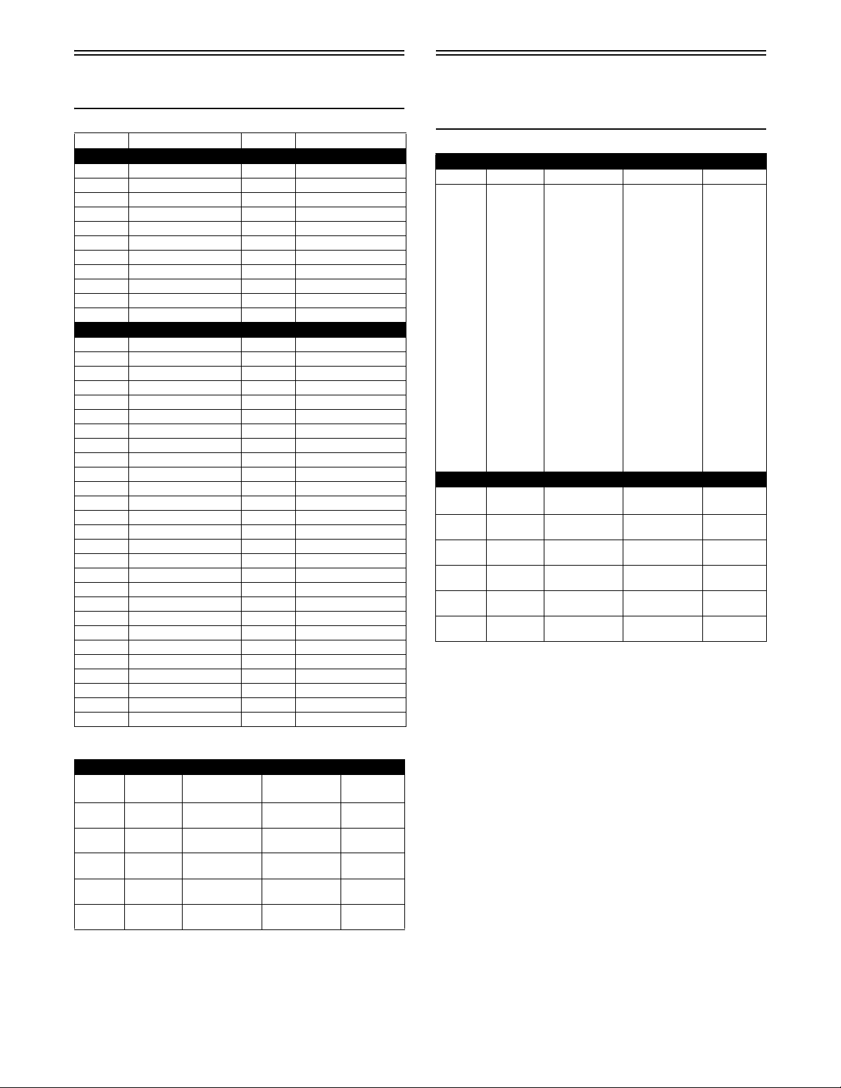
R-XC Team Drive Clutch
Optional Components
P/N DESCRIPTION P/N DESCRIPTION
DRIVE CLUTCH SPRINGS
0646-467 35/195 LB 0646-878 105/285 LB
0646-468 35/215 LB 0646-938 85/205 LB
0646-469 60/220 LB 0646-939 105/205 LB
0646-470 60/240 LB 0646-940 105/225 LB
0646-471 85/255 LB 0646-482 120/235 LB
0646-472 85/275 LB 0646-941 160/300 LB
0646-473 120/265 LB 0646-942 165/310 LB
0646-474 120/285 LB 0646-943 70/170 LB
0646-875 85/225 LB 0646-944 80/180 LB
0646-876 85/235 LB 0646-945 90/190 LB
0646-877 105/255 LB
CAM ARMS
0646-918 F7-48g 0646-901 J13-90g
0646-890 F7-50g 0646-902 J14-56g
0646-881 F7-52g 0646-871 J14-58g
0646-863 F7-54g 0646-867 J14-60g
0646-882 F7-56g 0646-872 J14-62g
0646-883 F7-58g 0646-903 J14-64g
0646-862 F7-60g 0646-869 J14-66g
0646-884 F7-62g 0646-904 J14-68g
0646-864 F7-64g 0646-905 J14-70g
0646-885 F7-66g 0646-906 J14-72g
0646-886 F7-68g 0646-907 J14-74g
0646-887 F7-70g 0646-924 J14-76g
0646-888 J13-60g 0646-930 J15-52g
0646-870 J13-62g 0646-929 J15-56g
0646-889 J13-64g 0646-908 J15-58g
0646-891 J13-66g 0646-909 J15-60g
0646-892 J13-68g 0646-910 J15-62g
0646-893 J13-70g 0646-873 J15-64g
0646-865 J13-72g 0646-911 J15-66g
0646-894 J13-74g 0646-912 J15-68g
0646-895 J13-76g 0646-913 J15-70g
0646-896 J13-78g 0646-914 J13-48g
0646-897 J13-80g 0646-915 J13-50g
0646-898 J13-82g 0646-874 J13-52g
0646-899 J13-84g 0646-868 J13-54g
0646-866 J13-86g 0646-916 J13-56g
0646-900 J13-88g 0646-917 J13-58g
R-SX Arctic Cat Drive
Clutch/Driven Clutch
Optional Components
ARCTIC CAT DRIVE CLUTCH SPRING CHART
p/n Rate @ 2 9/16”Rate @ 1 5/16” Color
LIGHT 0646-439 50 lb 250 lb Black/White
0646-148 53 lb 224 lb Blue
0646-150 72 lb 188 lb Silver
0646-149 74 lb 228 lb Red
0646-432 74 lb 228 lb Black/Red
0646-433 75 lb 275 lb Black/Gold
0646-376 75 lb 275 lb Gold
0646-252 103 lb 315 lb Green
0646-147 114 lb 267 lb Yellow/Green
0646-373* 114 lb 257 lb Yellow/Green
0646-155 121 lb 240 lb Purple
0646-229 122 lb 285 lb Yellow/White
0646-379* 122 lb 285 lb Yellow/White
0646-035 143 lb 286 lb Orange/
0646-447
(Titanium)
0646-367 143 lb 250 lb Black
0646-684 158 lb 285 lb Black
HEAVY 0646-410 165 lb 310 lb Black/Blue
143 lb 286 lb Pink
DRIVEN CLUTCH
Torque
Bracket
0648-779* 58-46-36/
0648-775* 52-42-46/
0648-773* 70-44-32/
0648-789* 68-48-36/
0648-791* 48-44-36/
Degree Spring Color
58-48-36
52-44-46
68-48-46
64-48-41
48-42-36
0648-749 Black/White 160/260
0648-702 Red/Black 140/240
0648-784 Black 155/222
0648-790 Black/Light Blue 180/260
0648-792 Black/Orange 180/280
*Lightweight driven clutch only.
Black
Spring
Rate
DRIVEN CLUTCH
Torque
Bracket
0648-779* 58-46-36/
0648-775* 52-42-46/
0648-773* 70-44-32/
0648-789* 68-48-36/
0648-791* 48-44-36/
Degree Spring Color
58-48-36
52-44-46
68-48-46
64-48-41
48-42-36
* Lightweight driven clutch only.
Spring
Rate
0648-749 Black/White 160/260
0648-702 Red/Black 140/240
0648-784 Black 155/222
0648-790 Black/Light Blue 180/260
0648-792 Black/Orange 180/280
7

R-SX Arctic Cat Drive
Clutch Cam Arms
(w/Set Screw)
ARCTIC CAT DRIVE CLUTCH CAM ARMS
p/n Grams p/n Grams
0746-661 52.0 0746-712 77.0
0746-662 52.0 0746-713 48.0
0746-663 52.0 0746-715 77.0
0746-664 52.0 0746-716 73.0
0746-666 55.0 0746-742 83.5
0746-668 55.0 0746-744 50.0
0746-669 60.0 0746-748 46.0
0746-670 65.0 0746-749 65.0
0746-671 70.0 0746-771 44.0
0746-672 75.0 0746-772 42.0
0746-673 80.0 0746-773 85.0
0746-676 70.0 0746-786 63.0
0746-678 55.0 0746-787 44.0
0746-687 57.0 0746-788 47.5
0746-689 69.0 0746-789 42.0
0746-690 47.0 0746-791 60.0
0746-691 44.0 0746-792 47.0
0746-692 50.0 0746-793 63.0
0746-694 63.0 0746-814 83.0
0746-695 67.0 0746-821 82.0
0746-696 63.0 0746-822 71.5
0746-698 64.0 0746-824 66.0
0746-699 66.0 0746-825 50.0
0746-701 49.0 0746-826 64.0*
0746-702 57.5 0746-830 60.0
0746-703 68.0
0746-704 51.0
0746-708 51.0
0746-710 72.0
* Notched Cam Arm
8

Chain Case Performance
Calibrations
NOTE: The following table should be used as a guide only. The vehicle speeds should be based on 12%
overdrive.
Drive
Sprocket
8 Tooth
(2.86"
pitch)
8 Tooth
(3.0" pitch)
9 Tooth
(2.52"
pitch)
Gear
Ratio
Top Btm
19 50 0.380 90 57 59 61 63 65 66 68 70 72 74 76 77 79 81 83
21 49 0.429 90 64 67 69 71 73 75 77 79 81 83 85 87 89 91 94
20 46 0.435 88 65 67 70 72 74 76 78 80 82 84 86 89 91 93 95
23 51 0.451 92 68 70 72 74 77 79 81 83 85 88 90 92 94 96 98
22 48 0.458 90 69 71 73 76 78 80 82 84 87 89 91 93 96 98 100
24 50 0.480 92 72 75 77 79 81 84 86 88 91 93 95 98 100 102 105
21 41 0.512 86 77 80 82 84 87 89 92 94 97 99 102 104 107 109 112
21 38 0.553 84 83 86 88 91 94 97 99 102 105 107 110 113 115 118 121
20 35 0.571 82 86 89 91 94 97 100 103 105 108 111 114 116 119 122 125
23 40 0.575 86 86 89 92 95 98 100 103 106 109 11 2 114 117 120 123 126
22 37 0.595 84 89 92 95 98 101 104 107 110 112 115 118 121 124 127 130
24 39 0.615 86 93 96 99 101 104 107 11 0 113 116 119 122 125 128 131 134
23 36 0.639 84 96 99 102 105 108 112 115 118 121 124 127 130 133 136 139
24 35 0.686 84 103 106 110 11 3 116 120 123 126 130 133 136 140 143 146 150
19 50 0.380 90 60 62 64 66 68 70 72 73 75 77 79 81 83 85 87
21 49 0.429 90 68 70 72 74 76 79 81 83 85 87 89 92 94 96 98
20 46 0.435 88 69 71 73 75 77 80 82 84 86 88 91 93 95 97 100
23 51 0.451 92 71 73 76 78 80 83 85 87 89 92 94 96 99 101 103
22 48 0.458 90 72 75 77 79 82 84 86 89 91 93 96 98 100 103 105
24 50 0.480 92 76 78 81 83 85 88 90 93 95 98 100 103 105 107 110
21 41 0.512 86 81 83 86 89 91 94 96 99 102 104 107 109 112 115 117
21 38 0.553 84 87 90 93 96 98 101 104 107 110 11 2 11 5 118 121 124 127
20 35 0.571 82 90 93 96 99 102 105 108 110 113 116 119 122 125 128 131
23 40 0.575 86 91 94 97 99 102 105 108 111 114 117 120 123 126 129 132
22 37 0.595 84 94 97 100 103 106 109 112 115 118 121 124 127 130 133 136
24 39 0.615 86 97 100 103 106 11 0 113 11 6 119 122 125 128 132 135 138 141
23 36 0.639 84 101 104 107 111 114 117 120 124 127 130 133 137 140 143 146
24 35 0.686 84 108 112 115 119 122 126 129 133 136 140 143 147 150 154 157
19 50 0.380 90 57 58 60 62 64 66 68 69 71 73 75 77 79 80 82
21 49 0.429 90 64 66 68 70 72 74 76 78 80 82 84 87 89 91 93
20 46 0.435 88 65 67 69 71 73 75 77 79 82 84 86 88 90 92 94
23 51 0.451 92 67 69 72 74 76 78 80 82 85 87 89 91 93 95 98
22 48 0.458 90 68 71 73 75 77 79 82 84 86 88 90 93 95 97 99
24 50 0.480 92 72 74 76 78 81 83 85 88 90 92 95 97 99 102 104
21 41 0.512 86 76 79 81 84 86 89 91 94 96 99 101 103 106 108 111
21 38 0.553 84 82 85 88 90 93 96 98 101 104 106 109 112 114 117 120
20 35 0.571 82 85 88 91 93 96 99 102 104 107 110 113 115 118 121 124
23 40 0.575 86 86 88 91 94 97 100 102 105 108 111 11 3 11 6 119 122 124
22 37 0.595 84 89 91 94 97 100 103 106 109 112 114 117 120 123 126 129
24 39 0.615 86 92 95 98 101 104 107 109 11 2 115 11 8 121 124 127 130 133
23 36 0.639 84 95 98 101 104 108 111 114 117 120 123 126 129 132 135 138
24 35 0.686 84 102 106 109 11 2 115 119 122 125 129 132 135 138 142 145 148
Ratio Chain Engine RPM
6200 6400 6600 6800 7000 7200 7400 7600 7800 8000 8200 8400 8600
Vehicle Speed (mph)
8800 9000
9

Drive
Sprocket
9 Tooth
(2.86"
pitch)
10 Tooth
(2.52"
pitch)
Gear
Ratio
Top Btm
19 50 0.380 90 64 66 68 71 73 75 77 79 81 83 85 87 89 91 93
21 49 0.429 90 73 75 77 80 82 84 87 89 91 94 96 98 101 103 105
20 46 0.435 88 74 76 78 81 83 85 88 90 93 95 97 100 102 104 107
23 51 0.451 92 76 79 81 84 86 89 91 94 96 98 101 103 106 108 111
22 48 0.458 90 78 80 83 85 88 90 93 95 98 100 103 105 108 110 113
24 50 0.480 92 81 84 86 89 92 94 97 100 102 105 107 110 113 115 118
21 41 0.512 86 87 89 92 95 98 101 103 106 109 112 115 117 120 123 126
21 38 0.553 84 93 97 100 103 106 109 112 115 11 8 121 124 127 130 133 136
20 35 0.571 82 97 100 103 106 109 112 115 118 122 125 128 131 134 137 140
23 40 0.575 86 97 100 104 107 11 0 113 11 6 119 122 126 129 132 135 138 141
22 37 0.595 84 101 104 107 110 114 117 120 123 127 130 133 136 140 143 146
24 39 0.615 86 104 107 111 11 4 118 121 124 128 131 134 138 141 144 148 151
23 36 0.639 84 108 112 115 119 122 126 129 132 136 139 143 146 150 153 157
24 35 0.686 84 11 6 120 123 127 131 135 138 142 146 150 153 157 161 165 168
19 50 0.380 90 63 65 67 69 71 73 75 77 79 81 83 85 87 89 91
21 49 0.429 90 71 73 76 78 80 82 85 87 89 92 94 96 98 101 103
20 46 0.435 88 72 74 77 79 81 84 86 88 91 93 95 98 100 102 105
23 51 0.451 92 75 77 80 82 84 87 89 92 94 96 99 101 104 106 108
22 48 0.458 90 76 78 81 83 86 88 91 93 96 98 100 103 105 108 110
24 50 0.480 92 80 82 85 87 90 92 95 97 100 103 105 108 110 113 115
21 41 0.512 86 85 88 90 93 96 99 101 104 107 109 112 115 118 120 123
21 38 0.553 84 92 94 97 100 103 106 109 11 2 115 11 8 121 124 127 130 133
20 35 0.571 82 95 98 101 104 107 110 113 116 119 122 125 128 131 134 137
23 40 0.575 86 95 98 101 104 108 111 114 11 7 120 123 126 129 132 135 138
22 37 0.595 84 98 102 105 108 111 114 118 121 124 127 130 133 137 140 143
24 39 0.615 86 102 105 108 11 2 115 118 122 125 128 132 135 138 141 145 148
23 36 0.639 84 106 109 113 116 119 123 126 130 133 137 140 143 147 150 154
24 35 0.686 84 11 4 117 121 125 128 132 136 139 143 147 150 154 158 161 165
Ratio Chain Engine RPM
6200 6400 6600 6800 7000 7200 7400 7600 7800 8000 8200 8400 8600
Vehicle Speed (mph)
8800 9000
NOTE: The above gearing options are combinations which allow acceptable chain tension. Any other
combinations will not allow acceptable chain tension.
10
Chains and Sprockets
p/n Sprocket
3602-170 19T FWD (13 WIDE/19 SPLINE) – Optional
3602-169 20T FWD (13 WIDE/19 SPLINE) – R-SX
2602-966 21T FWD (13 WIDE/19 SPLINE) – Optional
3602-171 22T FWD (13 WIDE/19 SPLINE) – Optional
2602-967 23T FWD (13 WIDE/19 SPLINE) – R-XC
2602-831 35T (13 WIDE/34 SPLINE)
2602-833 36T (13 WIDE/34 SPLINE)
2602-834 37T (13 WIDE/34 SPLINE)
2602-836 38T (13 WIDE/34 SPLINE)
2602-745 41T (13 WIDE/34 SPLINE)
2602-790 48T (13 WIDE/34 SPLINE)
2602-758 49T (13 WIDE/34 SPLINE)
2602-746 50T (13 WIDE/34 SPLINE)
2602-874 48T (13 WIDE/34 SPLINE) ALUM
2602-875 49T (13 WIDE/34 SPLINE) ALUM
2602-876 50T (13 WIDE/34 SPLINE) ALUM
Wire
p/n
1704-382/383
(Light)
1704-384/385
(Heavy)
1704-916/917 .405 120° 5.90 3.20 15.62 4.70 24
2704-224/225 .437 105° 6.80 3.75 15.62 4.70 27.3
1704-576/577 .405 90° 6.75 3.65 18.50 5.50 18.5
2704-384/385 .405 115° 6.80 3.65 15.62 4.70 18.9
2704-380/381** .437 92° 6.75 3.75 15.62 4.70 27.4
2704-382/383* .405 89° 6.75 3.65 15.62 4.70 18.9
Diameter
Angle
(A)
.359 90° 5.75 3.00 15.62 4.60 17
.375 90° 5.75 3.00 15.62 4.60 20
(B)
# of
Coils
Coil
Width
(C)
Length
(D)
Length
(E)
Degree
(In lb)
* Production (R-XC)
** Production (R-SX)
NOTE: The wire diameter and length of the spring
have a large influence over the valving of the shocks.
Installed Spring Rate
Chart
1702-402 40T TOS-ASSY
1702-403 49T TOS-ASSY
p/n Chain
2602-837 84P (13 WIDE)
2602-743 86P (13 WIDE)
2602-760 90P (13 WIDE)
2602-744 92P (13 WIDE)
2602-944 96P (13 WIDE)
2602-839 86P (15 WIDE)
2602-840 90P (15 WIDE)
2602-841 92P (15 WIDE)
Rear Spring Selection
Below is a list of rear suspension springs and specifications. A longer spring in areas (D) and (E) can be
selected if cut off to match the original spring. The
replacement spring must match the original spring in
areas (C), (D), and (E).
Suspension Fully
p/n
1704-382/383 1360 1700
1704-384/385 1600 2001
1704-916/917 480 960
2704-224/225 1350 1890
1704-576/577 1480 1850
2704-380/381 2082 2630
2704-382/383 1550 1928
2704-384/385 567 945
p/n
1704-382/383 3740 4080
1704-384/385 4411 4812
1704-916/917 3840 4320
2704-224/225 5130 5670
1704-576/577 4070 4440
2704-380/381 5918 6466
2704-382/383 4196 4574
2704-384/385 3213 3591
Extended
(in.-lb – Adjuster Set 1 & 1)
Suspension Fully
Collapsed
(in.-lb – Adjuster Set 1 & 1)
Suspension Fully
(in.-lb – Adjuster Set 3 & 3)
(in.-lb – Adjuster Set 3 & 3)
Extended
Suspension Fully
Collapsed
Front Suspension
Sway Bar
0730-218
Sway Bar p/n Bushing p/n Description
2703-615 2603-944/945 (inc.) 11.1 mm diameter
2703-793 2603-946/947 (inc.) 12.7 mm diameter
2703-794 2603.948/949 (inc.) 14.7 mm diameter
NOTE: Sway Bar Mounting Kit (p/n 6639-001).
11
Rebuildable Shock Tools
Required
Optional Dual Rate
Spring Chart (DSR)
p/n Tool
0744-020 Inflation Needle
0644-486 Gas Shock Retaining Blocks
0644-544 Replacement Needle
0644-169 Piston Location Tool
0644-151 Nitrogen Regulator
0644-268 Bearing Cap Seal Protector
0644-403 Bearing Cap Seal Protector (1/2-in. O.D. x 3/8 in. I.D.)
0644-404 Bearing Cap Seal Protector (5/8-in. O.D. x 3/8 in. I.D.)
0644-542 Bearing Cap Seal Protector (5/8 in. O.D. x 1/2 in. I.D.)
0644-543 Gas Shock Shaft Clamping Tool
0644-350 Floating Piston Location Gauge
0644-539 Inflation Needle Replacement Tip
0744-072 Float Shock Spanner Wrench
0644-584 Air Sleeve Bushing Installation Tool
0644-585 Air Sleeve Bushing Installation Tool
0644-456 Bullet Air Sleeve Bushing Installation Tool
Optional Front Arm
Shock Springs — R-XC
p/n lbs Length (Inches)
2704-755 100/250 7.75
2704-228 100/250 7.75
2704-229 160/260 7.75
1704-819 230 7.50
1704-820 170 7.50
1704-821 190 7.50
1704-822 210 7.50
1704-831 250 7.50
Ice Racing Springs
2704-749 70 6
2704-750 90 6
2704-751 110 6
Dual
Rate
100/200 200 lb x 2.15" 200 lb x 6” 1” 1.70”
90/200 170 lb x 2.20” 200 lb x 6” 1” 1.65”
80/200 140 lb x 2.40” 200 lb x 6” 1” 1.80”
50/200 70 lb x 2.55” 200 lb x 6” 1” 1.65”
110/250 200 lb x 2.15” 250 lb x 6” 1” 1.52”
100/250* 170 lb x 2.20” 250 lb x 6” 1” 1.50”
90/250 140 lb x 2.40” 250 lb x 6” 1” 1.75”
55/250 70 lb x 2.55” 250 lb x 6” 1” 1.60”
120/300 200 lb x 2.15” 300 lb x 6” 1” 1.40”
110-300 170 lb x 2.20” 300 lb x 6” 1” 1.40”
95/300 140 lb x 2.40” 300 lb x 6” 1” 1.60”
55/300 70 lb x 2.55” 300 lb x 6” 1” 1.55”
Ride-in
Spring
p/n 3704-037 p/n 3704-038 0.5” 2.70”
p/n 3704-036 p/n 3704-038 0.5” 2.50”
p/n 3704-035 p/n 3704-038 0.5” 2.65”
p/n 3704-033 p/n 3704-038 0.5” 2.30”
p/n 3704-037 p/n 3704-039 0.5” 2.41”
p/n 3704-036 p/n 3704-039 0.5” 2.33”
p/n 3704-035 p/n 3704-039 0.5” 2.50”
p/n 3704-033 p/n 3704-039 0.5” 2.25”
p/n 3704-037 p/n 3704-040 0.5” 2.25”
3704-036 p/n 3704-040 0.5” 2.20”
3704-035 p/n 3704-040 0.5” 2.35”
p/n 3704-033 p/n 3704-040 0.5” 2.15”
Take-over
Spring
Communication
Length
Transition
Point
* Stock Spring (R-XC)
Optional Front Arm
Shock Springs — R-SX
p/n lbs Length (Inches)
3704-094 90/250 8.25
3704-095 135 8.25
3704-152 300 7
3704-351 200 7
3704-352 225 7
3704-353* 250 7
3704-354 275 7
* Stock Spring
12

Valve Stacks/Specifications (R-XC)
Ski Shock Part Number Compression (Piston Side) Rebound (Piston Side)
3703-813 1.300 x 0.008 in. (DB) 1.100 x 0.010 in.
Extended Length: 18.98 in. 1.300 x 0.006 in. 0.800 x 0.006 in.
Collapsed Length: 13.28 in. 1.300 x 0.006 in. 1.125 x 0.080 in. (Backup)
Stroke: 5.7 in. 0.800 x 0.008 in. 0.750 x 0.080 in. (Backup)
1.300 x 0.008 in. 0.750 x 0.080 in. (Backup)
Rebuild Kit: p/n 3603-522 1.250 x 0.008 in. 0.750 x 0.080 in. (Backup)
1.100 x 0.008 in.
1.000 x 0.008 in.
0.900 x 0.008 in.
0.800 x 0.008 in.
IFP Depth: 1.8 in. 1.125 x 0.093 in. (Top Out)
Piston Orifice: None
QS3 @ 2nd Setting; RB Knob @ 12 clicks from full closed.
Eyelets tightened to 3.9 kg-m (28 ft-lb) (Green Loctite #620 on threads). Piston nut tightened to 3.0 kg-m (22 ft-lb).
Tighten shaft nut to 3.0 kg-m (22 ft-lb). Shocks charged at 250 psi.
Front Arm Shock Part Number Compression (Piston Side) Rebound (Piston Side)
3704-348 1.300 x 0.010 (SB) 1.100 x 0.010 in.
Extended Length: 12.41 in. 1.300 x 0.006 in. 1.100 x 0.010 in.
Collapsed Length: 8.63 in. 1.300 x 0.006 in. 1.000 x 0.010 in.
Stroke: 3.78 in. 1.300 x 0.006 in. 0.900 x 0.010 in.
0.700 x 0.006
Rebuild Kit: p/n 4604-189 1.300 x 0.008 in. 0.700 x 0.010 in.
1.250 x 0.008 in. 0.620 x 0.080 in. (Backup)
1.100 x 0.008 in.
1.000 x 0.008 in.
IFP Depth: 1.4 in. 0.800 x 0.008 in.
Piston Orifice: None 0.700 x 0.008 in.
1.125 x 0.080 in. (Top Out)
QS3 @ 2nd Setting. Eyelets tightened to 3.9 kg-m (28 ft-lb) (Green Loctite #620 on threads).
Piston nut tightened to 3.0 kg-m (22 ft-lb). Tighten shaft nut to 3.9 kg-m (28 ft-lb). Shock charged at 250 psi.
0.800 x 0.010 in.
0.620 x 0.080 in. (Backup)
Rear Arm Shock Part Number
3704-342 1.600 x 0.004 in. (XSB) 1.425 x 0.015 in.
Extended Length: 14.44 in. 1.600 x 0.010 in. 1.425 x 0.015 in.
Collapsed Length: 10.02 in. 1.600 x 0.010 in. 1.425 x 0.012 in.
Stroke: 4.42 in. 1.100 x 0.006 in. 1.350 x 0.012 in.
Rebuild Kit: p/n 4604-160 1.600 x 0.012 in. 0.950 x 0.012 in.
Piston Depth: 2.10 in. 1.570 x 0.128 in. (Top Out)
Piston Orifice: None
Compression
(Piston Side)
1.600 x 0.012 in. 1.100 x 0.012 in.
1.600 x 0.012 in. 0.800 x 0.020 in.
1.425 x 0.010 in. 0.800 x 0.020 in.
1.350 x 0.010 in. 0.750 x 0.080 in. (Backup)
1.100 x 0.008 in. 0.750 x 0.100 in. (Backup)
Rebound (Piston Side)
QS3 @ 2nd Setting; RB Knob @ 4 clicks counterclockwise. Shock charged at 250 psi.
Eyelets tightened to 3.9 kg-m (28 ft-lb) (Green Loctite #620 on threads). Piston nut tightened to 3.0 kg-m (22 ft-lb).
Tighten the shaft nut to 3.9 kg-m (28 ft-lb).
13

Valve Stacks/Specifications (R-SX)
Ski Shock Part Number Compression (Piston Side) Rebound (Piston Side)
3703-948/949 1.300 x 0.006 in. 1.100 x 0.008 in.
Extended Length: 19.14 in. 1.300 x 0.008 in. 0.600 x 0.004 in.
Collapsed Length: 13.29 in. 1.300 x 0.010 in. 0.800 x 0.006 in.
Stroke: 5.85 in. 1.100 x 0.012 1.125 x 0.080 in. (Ground)
1.250 x 0.015 (Ring) 0.0950 x 0.050 (Top Out)
Rebuild Kit: p/n 3603-420 1.300 x 0.010 in.
0.800 x 0.004 in.
1.300 x 0.012 in.
1.300 x 0.012 in.
1.250 x 0.010 in.
IFP Depth: 2.30 in. 1.000 x 0.015 in.
Piston Orifice: None 1.125 x 0.093 in. (Top Out Washer)
Low Speed Compression Knob @ 8 clicks counterclockwise from full stop; RB Knob @ 5 clicks counterclockwise from full stop.
Eyelets tightened to 3.9 kg-m (28 ft-lb) (threads coated with Green Loctite #620). Piston nut tightened to 3.0 kg-m (22 ft-lb).
Shaft nut tightened to 3.0 kg-m (22 ft-lb). Shocks charged at 350 psi (nitrogen)/150/275 psi (air).
Front Arm Shock Part Number Compression (Piston Side) Rebound (Piston Side)
3704-466 1.600 x 0.004 in. SB 1.425 x 0.008 in.
Extended Length: 12.34 in. 1.600 x 0.008 in. 0.850 x 0.004 in.
Collapsed Length: 8.29 in. 1.600 x 0.008 in. 1.400 x 0.080 in. (Top Out)
Stroke: 4.05 in. 1.425 x 0.008 in. 0.750 x 0.080 in. (Backup)
1.600 x 0.012 in. (Ring)
Rebuild Kit: p/n 4604-318 1.600 x 0.008 in.
1.420 x 0.008 in.
1.350 x 0.008 in.
1.200 x 0.008 in.
1.000 x 0.008 in.
IFP Depth: 1.80 in. 1.570 x 0.080 in. (Top Out Washer)
Piston Orifice: None
Low Speed Compression (Initial Setting): 18 clicks from fully closed. Eyelets tightened to 3.9 kg-m (28 ft-lb). Piston nut tightened to 3.0 kg-m (22
ft-lb). Tighten shaft nut to 3.9 kg-m (28 ft-lb). Shock charged at 350 psi. Green Loctite #620 on shock eyelet threads.
Rear Arm Shock Part Number Compression (Piston Side) Rebound (Piston Side)
3704-467 1.600 x 0.004 in. (XSB) 1.425 x 0.015 in.
Extended Length: 14.39 in. 1.600 x 0.008 in.
Collapsed Length: 10.06 in. 1.600 x 0.010 1.400 x 0.080 in. (Top Out)
Stroke: 4.32 in. 1.425 x 0.012 in.
1.600 x 0.015 (Ring) 1.400 x 0.080 in. (Top Out)
1.600 x 0.008 in.
Rebuild Kit: p/n 4604-017 1.100 x 0.0045 in.
1.600 x 0.012 in.
IFP Depth: 2.30 in. 1.600 x 0.012 in.
Piston Orifice: None 1.600 x 0.012 in.
1.600 x 0.012 in.
1.600 x 0.012 in.
1.600 x 0.012 in.
1.600 x 0.012 in.
1.600 x 0.012 in.
1.600 x 0.012 in.
1.425 x 0.012 in.
1.350 x 0.012 in.
1.250 x 0.012 in.
1.100 x 0.008 in.
1.000 x 0.010 in.
1.570 x 0.128 in. (Top Out)
Low Speed Compression: 18 positions counterclockwise from full stop. Rebound 8 clicks counterclockwise from full stop.
Shock charged at 350 psi. Green Loctite #620 on shock eyelet threads.
Eyelets tightened to 3.9 kg-m (28 ft-lb). Piston nut tightened to 3.0 kg-m (22 ft-lb). Tighten the shaft nut to 3.9 kg-m (28 ft-lb).
14

Rebuildable Shock
Accessory Part Numbers
NOTE: When rebuilding FOX shocks, use only
FOX valves and/or pistons.
Acc p/n Description
2603-499 Valve: [0.500 OD X 0.252 ID X 0.006 TH]
2603-500 Valve: [0.600 OD X 0.252 ID X 0.010 TH]
2603-501 Valve: [0.700 OD X 0.252 ID X 0.010 TH]
2603-902 Valve: [0.550 OD X 0.377 ID X 0.020 TH]
3604-171 Valve: [0.600 OD X 0.377 ID X 0.004 TH]
3604-533 Valve: [0.600 OD X 0.377 ID X 0.012 TH]
2603-224 Valve: [0.620 OD X 0.377 ID X 0.015 TH]
0603-731 Valve: [0.700 OD X 0.377 ID X 0.004 TH]
0603-330 Valve: [0.700 OD X 0.377 ID X 0.006 TH]
0603-331 Valve: [0.700 OD X 0.377 ID X 0.008 TH]
0603-332 Valve: [0.700 OD X 0.377 ID X 0.010 TH]
0603-878 Valve: [0.700 OD X 0.377 ID X 0.012 TH]
0603-884 Valve: [0.700 OD X 0.377 ID X 0.015 TH]
0603-895 Valve: [0.800 OD X 0.377 ID X 0.004 TH]
0603-333 Valve: [0.800 OD X 0.377 ID X 0.006 TH]
0603-334 Valve: [0.800 OD X 0.377 ID X 0.008 TH]
0603-335 Valve: [0.800 OD X 0.377 ID X 0.010 TH]
0603-879 Valve: [0.800 OD X 0.377 ID X 0.012 TH]
0603-885 Valve: [0.800 OD X 0.377 ID X 0.015 TH]
0603-894 Valve: [0.900 OD X 0.377 ID X 0.004 TH]
0603-336 Valve: [0.900 OD X 0.377 ID X 0.006 TH]
0603-337 Valve: [0.900 OD X 0.377 ID X 0.008 TH]
0603-338 Valve: [0.900 OD X 0.377 ID X 0.010 TH]
0603-880 Valve: [0.900 OD X 0.377 ID X 0.012 TH]
0603-886 Valve: [0.900 OD X 0.377 ID X 0.015 TH]
0603-893 Valve: [1.000 OD X 0.377 ID X 0.004 TH]
0603-339 Valve: [1.000 OD X 0.377 ID X 0.006 TH]
0603-340 Valve: [1.000 OD X 0.377 ID X 0.008 TH]
0603-341 Valve: [1.000 OD X 0.377 ID X 0.010 TH]
0603-881 Valve: [1.000 OD X 0.377 ID X 0.012 TH]
0603-887 Valve: [1.000 OD X 0.377 ID X 0.015 TH]
0603-892 Valve: [1.100 OD X 0.377 ID X 0.004 TH]
0603-342 Valve: [1.100 OD X 0.377 ID X 0.006 TH]
0603-343 Valve: [1.100 OD X 0.377 ID X 0.008 TH]
0603-344 Valve: [1.100 OD X 0.377 ID X 0.010 TH]
0603-882 Valve: [1.100 OD X 0.377 ID X 0.012 TH]
0603-888 Valve: [1.100 OD X 0.377 ID X 0.015 TH]
0603-345 Valve: [1.250 OD X 0.377 ID X 0.006 TH]
0603-346 Valve: [1.250 OD X 0.377 ID X 0.008 TH]
0603-347 Valve: [1.250 OD X 0.377 ID X 0.010 TH]
0603-883 Valve: [1.250 OD X 0.377 ID X 0.012 TH]
0603-889 Valve: [1.250 OD X 0.377 ID X 0.015 TH]
0603-348 Valve: [1.300 OD X 0.377 ID X 0.006 TH]
0603-349 Valve: [1.300 OD X 0.377 ID X 0.008 TH]
0603-350 Valve: [1.300 OD X 0.377 ID X 0.010 TH]
0603-891 Valve: [1.300 OD X 0.377 ID X 0.012 TH]
0603-890 Valve: [1.300 OD X 0.377 ID X 0.015 TH]
Acc p/n Description
2604-647 Valve: [1.425 OD X 0.377 ID X 0.010 TH]
2604-632 Valve: [1.425 OD X 0.377 ID X 0.012 TH]
2604-633 Valve: [1.425 OD X 0.377 ID X 0.015 TH]
3604-577 Valve: [1.600 OD X 0.377 ID X 0.008 TH]
2604-631 Valve: [1.600 OD X 0.377 ID X 0.010 TH]
2604-683 Valve: [0.650 OD X 0.504 ID X 0.020 TH]
2604-469 Valve: [0.700 OD X 0.504 ID X 0.010 TH]
2604-470 Valve: [0.700 OD X 0.504 ID X 0.020 TH]
2604-471 Valve: [0.750 OD X 0.504 ID X 0.020 TH]
2604-472 Valve: [0.800 OD X 0.504 ID X 0.006 TH]
2604-473 Valve: [0.800 OD X 0.504 ID X 0.008 TH]
2604-474 Valve: [0.800 OD X 0.504 ID X 0.010 TH]
2604-475 Valve: [0.800 OD X 0.504 ID X 0.012 TH]
2604-476 Valve: [0.800 OD X 0.504 ID X 0.015 TH]
2604-477 Valve: [0.800 OD X 0.504 ID X 0.020 TH]
2604-478 Valve: [0.950 OD X 0.504 ID X 0.006 TH]
2604-479 Valve: [0.950 OD X 0.504 ID X 0.008 TH]
2604-480 Valve: [0.950 OD X 0.504 ID X 0.010 TH]
2604-481 Valve: [0.950 OD X 0.504 ID X 0.012 TH]
2604-482 Valve: [0.950 OD X 0.504 ID X 0.015 TH]
2604-483 Valve: [1.000 OD X 0.504 ID X 0.020 TH]
3604-149 Valve: [1.100 OD X 0.504 ID X 0.004 TH]
2604-484 Valve: [1.100 OD X 0.504 ID X 0.006 TH]
2604-485 Valve: [1.100 OD X 0.504 ID X 0.008 TH]
2604-486 Valve: [1.100 OD X 0.504 ID X 0.010 TH]
2604-487 Valve: [1.100 OD X 0.504 ID X 0.012 TH]
2604-488 Valve: [1.100 OD X 0.504 ID X 0.015 TH]
2604-489 Valve: [1.100 OD X 0.504 ID X 0.020 TH]
2604-684 Valve: [1.250 OD X 0.504 ID X 0.006 TH]
2604-685 Valve: [1.250 OD X 0.504 ID X 0.008 TH]
2604-686 Valve: [1.250 OD X 0.504 ID X 0.010 TH]
2604-687 Valve: [1.250 OD X 0.504 ID X 0.012 TH]
2604-688 Valve: [1.250 OD X 0.504 ID X 0.015 TH]
2604-490 Valve: [1.350 OD X 0.504 ID X 0.006 TH]
2604-491 Valve: [1.350 OD X 0.504 ID X 0.008 TH]
2604-492 Valve: [1.350 OD X 0.504 ID X 0.010 TH]
2604-493 Valve: [1.350 OD X 0.504 ID X 0.012 TH]
2604-494 Valve: [1.350 OD X 0.504 ID X 0.015 TH]
2604-495 Valve: [1.425 OD X 0.504 ID X 0.006 TH]
2604-496 Valve: [1.425 OD X 0.504 ID X 0.008 TH]
2604-497 Valve: [1.425 OD X 0.504 ID X 0.010 TH]
2604-498 Valve: [1.425 OD X 0.504 ID X 0.012 TH]
2604-499 Valve: [1.425 OD X 0.504 ID X 0.015 TH]
2604-500 Valve: [1.600 OD X 0.504 ID X 0.006 TH]
2604-501 Valve: [1.600 OD X 0.504 ID X 0.008 TH]
2604-502 Valve: [1.600 OD X 0.504 ID X 0.010 TH]
2604-503 Valve: [1.600 OD X 0.504 ID X 0.012 TH]
2604-504 Valve: [1.600 OD X 0.504 ID X 0.015 TH]
NOTE: Shock Oil (p/n 5639-530) is available from
Arctic Cat Service Department.
15
Double Bleed Shims (DB)
Acc p/n Description
3603-342 Valve: DB 3 PORT (1.30" OD X .375" ID .004" THK.)
3603-343 Valve: DB 3 PORT (1.30" OD X .375" ID .006" THK.)
3603-344 Valve: DB 3 PORT (1.30" OD X .375" ID .008" THK.)
3603-345 Valve: DB 3 PORT (1.30" OD X .375" ID .010" THK.)
3603-346 Valve: DB 3 PORT (1.30" OD X .375" ID .012" THK.)
3603-347 Valve: DB 3 PORT (1.30" OD X .375" ID .015" THK.)
3603-348 Valve: DB 3 PORT (1.30" OD X .375" ID .020" THK.)
3603-481 Valve: DB 4 PORT (1.60" OD X .502" ID .004" THK.)
3603-482 Valve: DB 4 PORT (1.60" OD X .502" ID .006" THK.)
3603-483 Valve: DB 4 PORT (1.60" OD X .502" ID .008" THK.)
3603-484 Valve: DB 4 PORT (1.60" OD X .502" ID .010" THK.)
3603-485 Valve: DB 4 PORT (1.60" OD X .502" ID .012" THK.)
3603-486 Valve: DB 4 PORT (1.60" OD X .502" ID .015" THK.)
3603-487 Valve: DB 4 PORT (1.60" OD X .502" ID .020" THK.)
Single Bleed Shims (DB)
Acc p/n Description
3603-469 Valve: SB 3 PORT (1.30" OD X .375" ID .004" THK.)
3603-470 Valve: SB 3 PORT (1.30" OD X .375" ID .006" THK.)
4604-038 Valve: SB 3 PORT (1.30" OD X .375" ID .008" THK.)
3603-471 Valve: SB 3 PORT (1.30" OD X .375" ID .010" THK.)
3603-472 Valve: SB 3 PORT (1.30" OD X .375" ID .012" THK.)
3603-473 Valve: SB 3 PORT (1.30" OD X .375" ID .015" THK.)
3603-474 Valve: SB 3 PORT (1.30" OD X .375" ID .020" THK.)
3603-475 Valve: SB 4 PORT (1.60" OD X .502" ID .004" THK.)
3603-410 Valve: SB 4 PORT (1.60" OD X .502" ID .006" THK.)
3603-476 Valve: SB 4 PORT (1.60" OD X .502" ID .005" THK.)
3603-477 Valve: SB 4 PORT (1.60" OD X .502" ID .010" THK.)
3603-478 Valve: SB 4 PORT (1.60" OD X .502" ID .012" THK.)
3603-479 Valve: SB 4 PORT (1.60" OD X .502" ID .015" THK.)
3603-480 Valve: SB 4 PORT (1.60" OD X .502" ID .020" THK.)
Drill Bit Sizes
(Number) Chart
Size of
Drill in
No.
Inches
1 .228021.159041 .0960 61 .0390
2 .221022.157042 .0935 62 .0380
3 .213023.154043 .0890 63 .0370
4 .209024.152044 .0860 64 .0360
5 .205525.149545 .0820 65 .0350
6 .204026.147046 .0810 66 .0330
7 .201027.144047 .0785 67 .0320
8 .199028.140548 .0760 68 .0310
9 .196029.136049 .0730 69 .0292
10 .193530.128550 .0700 70 .0280
11 .191031.120051 .0670 71 .0260
12 .189032.116052 .0635 72 .0250
13 .185033.113053 .0595 73 .0240
14 .182034.111054 .0550 74 .0225
15 .180035.110055 .0520 75 .0210
16 .177036.106556 .0465 76 .0200
17 .173037.104057 .0430 77 .0180
18 .169538.101558 .0420 78 .0160
19 .166039.099559 .0410 79 .0145
20 .161040.098060 .0400 80 .0135
No.
Size of
Drill in
Inches
No.
Size of
Drill in
Inches
No.
Size of
Drill in
Inches
Fraction/Decimal
Conversion Chart
8ths 16ths 32nds 64ths 64ths (cont)
1/8 = .125 1/16 = .0625 1/32 = .03125 1/64 = .015625 33/64 = .515625
1/4 = .250 3/16 = .1875 3/32 = .09375 3/64 = .046875 35/64 = .546875
3/8 = .375 5/16 = .3125 5/32 = .15625 5/64 = .078125 37/64 = .578125
1/2 = .500 7/16 = .4375 7/32 = .21875 7/64 = .109375 39/64 = .609375
5/8 = .625 9/16 = .5625 9/32 = .28125 9/64 = .140625 41/64 = .640625
3/4 = .750 11/16 = .6875 11/32 = .34375 11/64 = .171875 43/64 = .671875
7/8 = .875 13/16 = .8125 13/32 = .40625 13/64 = .203125 45/64 = .703125
— 15/16 = .9375 15/32 = .46875 15/64 = .234370 47/64 = .734375
— — 17/32 = .53125 17/64 = .265625 49/64 = .765625
— — 19/32 = .59375 19/64 = .296875 51/64 = .796875
— — 21/32 = .65625 21/64 = .328125 53/64 = .828125
— — 23/32 = .71875 23/64 = .359375 55/64 = .859375
— — 25/32 = .78125 25/64 = .390625 57/64 = .890625
— — 27/32 = .84375 27/64 = .421875 59/64 = .921875
— — 29/32 = .90625 29/64 = .453125 61/64 = .953125
— — 31/32 = .96875 31/64 = .484375 63/64 = .984375
16

Conversion Chart
(mm/in.)
mm in. mm in. mm in. mm in.
.01 .00039 .51 .02008 1 .03937 51 2.00787
.02 .00079 .52 .02047 2 .07874 52 2.04724
.03 .00118 .53 .02087 3 .11811 53 2.08661
.04 .00157 .54 .02126 4 .15748 54 2.12598
.05 .00197 .55 .02165 5 .19685 55 2.16535
.06 .00236 .56 .02205 6 .23622 56 2.20472
.07 .00276 .57 .02244 7 .27559 57 2.24409
.08 .00315 .58 .02283 8 .31496 58 2.28346
.09 .00354 .59 .02323 9 .35433 59 2.32283
.10 .00394 .60 .02362 10 .39370 60 2.36220
.11 .00433 .61 .02402 11 .43307 61 2.40157
.12 .00472 .62 .02441 12 .47244 62 2.44094
.13 .00512 .63 .02480 13 .51181 63 2.48031
.14 .00551 .64 .02520 14 .55118 64 2.51968
.15 .00591 .65 .02559 15 .59055 65 2.55905
.16 .00630 .66 .02598 16 .62992 66 2.59842
.17 .00669 .67 .02638 17 .66929 67 2.63779
.18 .00709 .68 .02677 18 .70866 68 2.67716
.19 .00748 .69 .02717 19 .74803 69 2.71653
.20 .00787 .70 .02756 20 .78740 70 2.75590
.21 .00827 .71 .02795 21 .82677 71 2.79527
.22 .00866 .72 .02835 22 .86614 72 2.83464
.23 .00906 .73 .02874 23 .90551 73 2.87401
.24 .00945 .74 .02913 24 .94488 74 2.91338
.25 .00984 .75 .02953 25 .98425 75 2.95275
.26 .01024 .76 .02992 26 1.02362 76 2.99212
.27 .01063 .77 .03032 27 1.06299 77 3.03149
.28 .01102 .78 .03071 28 1.10236 78 3.07086
.29 .01142 .79 .03110 29 1.14173 79 3.11023
.30 .01181 .80 .03150 30 1.18110 80 3.14960
.31 .01220 .81 .03189 31 1.22047 81 3.18897
.32 .01260 .82 .03228 32 1.25984 82 3.22834
.33 .01299 .83 .03268 33 1.29921 83 3.26771
.34 .01339 .84 .03307 34 1.33858 84 3.30708
.35 .01378 .85 .03346 35 1.37795 85 3.34645
.36 .01417 .86 .03386 36 1.41732 86 3.38582
.37 .01457 .87 .03425 37 1.45669 87 3.42519
.38 .01496 .88 .03465 38 1.49606 88 3.46456
.39 .01535 .89 .03504 39 1.53543 89 3.50393
.40 .01575 .90 .03543 40 1.57480 90 3.54330
.41 .01614 .91 .03583 41 1.61417 91 3.58267
.42 .01654 .92 .03622 42 1.65354 92 3.62204
.43 .01693 .93 .03661 43 1.69291 93 3.66141
.44 .01732 .94 .03701 44 1.73228 94 3.70078
.45 .01772 .95 .03740 45 1.77165 95 3.74015
.46 .01811 .96 .03780 46 1.81102 96 3.77952
.47 .01850 .97 .03819 47 1.85039 97 3.81889
.48 .01890 .98 .03858 48 1.88976 98 3.85826
.49 .01929 .99 .03898 49 1.92913 99 3.89763
.50 .01969 1.0 .03937 50 1.96850 100 3.93700
17

NOTES
18
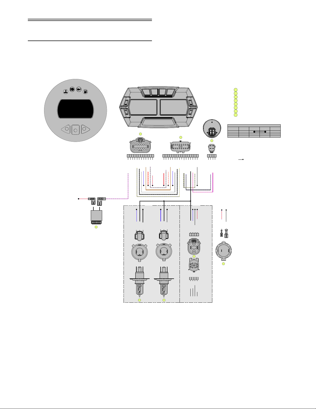
Wiring Diagram —
SPEEDOMETER/TACHOMETER
CONNECTOR, MAIN HARNESS
HEADLIGHT, HALOGEN B
CONNECTOR, KEYSWITCH
OUTLET, 12V ACCESSORY
HEADLIGHT, HALOGEN A
HEADLIGHT, LED
1
2
3
4
5
6
7
3
13
Lo Beam LEDs
((-)) BLK/VLT
8
(Battery (+)) RED/WHT
9
6
14
7
5
11
1
10
15
(Low Oil) BRN
4
12
(Can L) GRY/YEL
(Fuel Level Sensor) GRY
16
2
(Fuel level Sensor) GRY
(Speedo/Tach Power) RED/BLU
(Battery (+)) RED/WHT
(Can H) WHT/GRY
(Can H) WHT/GRY
(Gauge (-)) BLK/VLT
ABD
C
ABCD
(Keyswitch (+)) VLT/RED
(Low Oil) BRN
(Can L) GRY/YEL
(Hi Beam Power) BLU
(Starter Solenoid) BLK/YEL
(Keyswitch Ground) BLK/BLU
1
2
3456
14
1312
11
10
9
15
7
16
8
BLK (Ground)
RED/BLU (Power)
(Hi Beam Power) BLU
(Keyswitch Ground) BLK/BLU
(Reverse Alarm) VLT/BLK
(Lo Beam Power) WHT
(Ground) BLK
(Starter Solenoid) BLK/YEL
(Keyswitch (+)) VLT/RED
2
3
4
1
1234
12
WHT (Lo Beam Power)
BLU (Hi Beam Power)
BLK (Ground)
RED/BLU (Low Power DC)
LED
HEADLIGHT
Hi Beam LEDs
Ground
Accent Lighting LEDs
BLK (Ground)
BLU (Hi Beam)
WHT (Lo Beam)
BLK (Ground)
BLU (Hi Beam)
WHT (Lo Beam)
HALOGEN
HEADLIGHT
(Low Power DC) RED/BLU
CIRCUIT DIAGRAM"
SWITCH
FUNCTION
TERMINAL
"A"
TERMINAL
"B"
TERMINAL
"C"
TERMINAL
"D"
OFF
ON
START
5
4
6
3
2
1
7
8
12
11 10 9
12611510493827
1
A
BC
D
#2
#1
#2#1
+
-
A
B
C
AC
B
A
B
C
AC
B
4321
12
34
1
2
3
4
5
7
6
RED/BLU
VLT/BLK
#1#2
8
8
ALARM, REVERSE
NOTES:
1. CONNECTORS SHOWN FROM MATING SURFACE SIDE.
2. INDICATES WIRE SPLICE, THIS EXAMPLE
INDICATES BLK SPLICE A.
BLK
A
Hood Harness (R-XC)
(p/n 1686-856, 1686-857)
0752-740
19
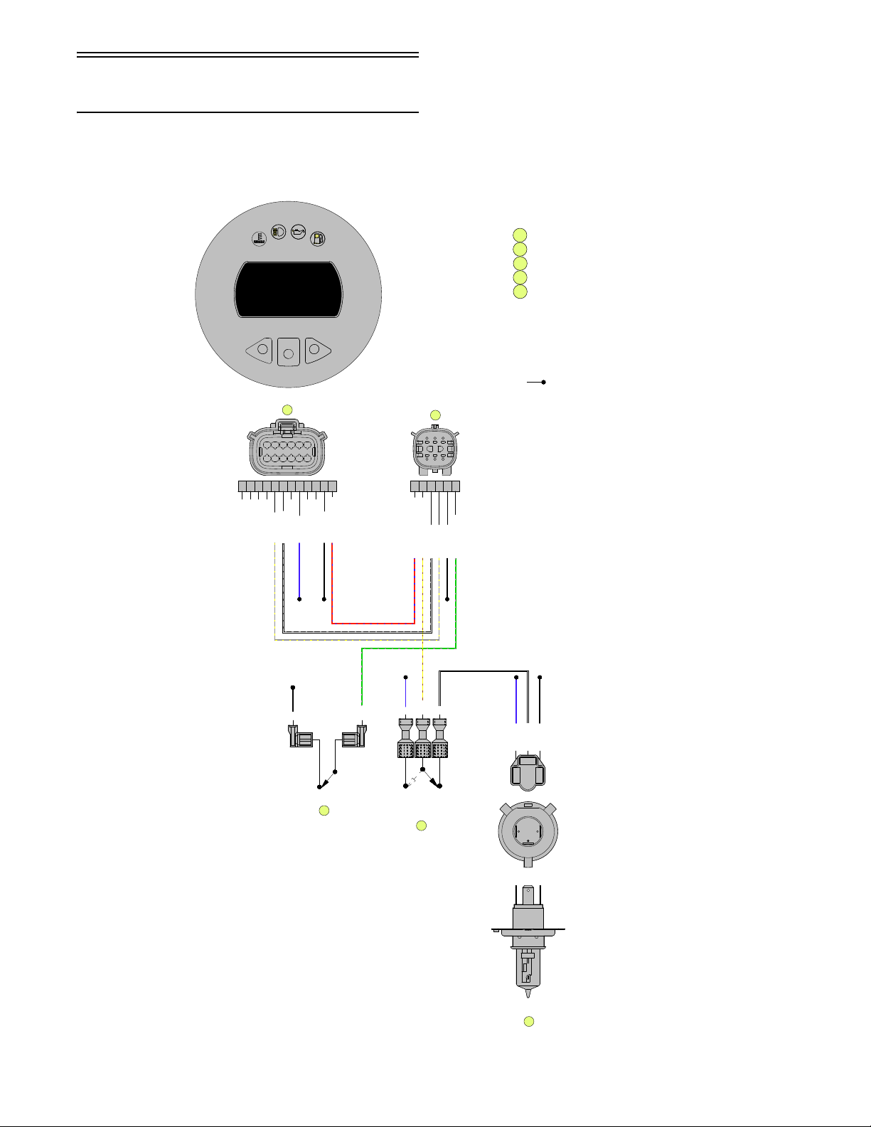
Wiring Diagram —
1
2
3
4
A
B
C
AC
B
1
2
3
4
CONNECTOR, SPEEDOMETER
CONNECTOR, MAIN HARNESS
HEADLIGHT
SWITCH, HEADLIGHT
(Warmer Switch) GRN/VLT
OPEN @ OFF
CLOSED @ ON
#2
BLK
GRN/VLT
#1
5
SWITCH, WARMER
5
NOTES:
1. CONNECTORS SHOWN FROM MATING SURFACE SIDE.
WHERE APPLICABLE.
2. INDICATES WIRE SPLICE, THIS EXAMPLE
INDICATES BLK SPLICE.
5
4
WHT (Lo Beam)
(Headlight Fused AC Power) YEL/VLT
YEL/VLT
BLK (Grounnd)
4
WHT
1
(CAN Hi) WHT/GRY
BLU (Hi Beam)
6
(Chassis Gnd) BLK
3
BLU
2
6
5
BLU + YEL/VLT = HI BEAMS ON
WHT + YEL/VLT = LO BEAMS ON
3
2
1
7
8
12
11 10 9
(Chassis Gnd) BLK
(Fused DC Power) RED/BLU
(Fused DC Power) RED/BLU
(CAN Lo) GRY/YEL
(CAN Lo) GRY/YEL
(CAN Hi) WHT/GRY
(Hi Beams) BLU
12611510493827
1
36251
4
#1
#3
#2
BLK
Hood Harness (R-SX)
(p/n 1686-880)
20
0752-739

Wiring Diagram —
Ignition/Main Harness
(R-XC)
(p/n 1686-833)
(Insert 0752-737 11 x 17 in color here.)


Wiring Diagram —
Ignition/Main Harness
(R-SX)
(p/n 1686-876)
(Insert 0752-738 11 x 17 in color here.)

Setup Instructions
This snowmobile has been prepared at the factory to
minimize required setup items; however, there are
some items and inspections that must be done at a
dealership or by the owner/operator. Please pay close
attention to all items on the following pages. Be sure to
read these instructions thoroughly before starting to set
up the snowmobile.
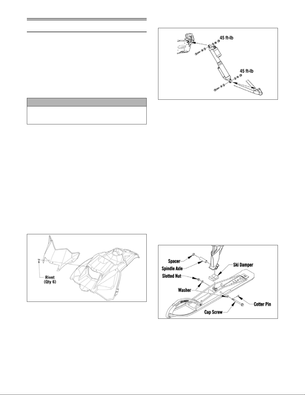
Removing Snowmobile from Crate/ Installing Handlebar Assembly
Installing Front Shock Absorbers
CAUTION
Care should be taken when removing the snowmobile
from the crate. Damage that is not warrantable may
occur.
1. Remove the top and four sides of the crate.
Remove the skis from the crate sides.
2. Remove the windshield and hardware kit.
3. Remove all mounting hardware securing the
snowmobile to the crate base; then lift the snowmobile free of the crate base.
4. Swing the handlebar up and tighten the cap screws
evenly to 15 ft-lb; then check steering for maximum right/left turning capabilities. Install the handlebar pad assembly.
Installing Windshield
1. Remove the protective film from the windshield.
2. Place the windshield into position on the console and
secure using the six plastic rivets.
746-484B
1. Raise the front of the snowmobile and place it on a
support stand.
2. Apply grease to the O-rings; then install the O-rings
and the spherical spacers to each side of the shock
eyelet spherical bearing. Take care that the O-ring is
between the bearing and spherical spacers.
3. Place the upper shock into position on the frame;
then install the cap screw and flange nut. Tighten
to 45 ft-lb.
4. Install the lower shock eyelet into the lower A-arm
mounting bracket.
5. Push the cap screw through the shock eyelet and
backside of the A-arm mounting bracket; then
install the nut and tighten to 45 ft-lb.
6. Install the remaining shock absorber.
Installing Skis (R-SX)
1. Slide a washer onto the cap screw used to secure the
ski; then apply all-temperature grease to the shaft
portion of the cap screw and spindle axle.
0752-635
0752-634
2. Install the spindle axle into the spindle; then position the
ski damper into the bottom of the ski making sure the
damper is properly positioned for the desired ski stance.
NOTE: The ski damper must be positioned in the ski
so it is directly under the spindle.
3. With the cap screw hole of the ski centered with the
spindle axle, slide the cap screw with washer through
the outside of the ski and spindle assemblies.
25
 Loading...